

Page 1

General-Purpose AC Servo
compatible
LINEAR ENCODER
INSTRUCTION MANUAL
F
Page 2
Safety Instructions
Please read the instructions carefully before using the equipment.
Do not attempt to install, operate, maintain or inspect the equipment until you have read through this
Instruction Manual and appended documents carefully and can use the equipment correctly. Do not use the
equipment until you have a full knowledge of the equipment, safety information and instructions.
In this Instruction Manual, the safety instruction levels are classified into "WARNING" and "CAUTION".
WARNING
CAUTION
Note that the CAUTION level may lead to a serious consequence according to conditions.
Please follow the instructions of both levels because they are important to personnel safety.
What must not be done and what must be done are indicated by the following diagrammatic symbols.
Indicates that incorrect handling may cause hazardous conditions,
resulting in death or severe injury.
Indicates that incorrect handling may cause hazardous conditions,
resulting in medium or slight injury to personnel or may cause physical
damage.
Indicates what must not be done. For example, "No Fire" is indicated by .
Indicates what must be done. For example, grounding is indicated by .
In this Instruction Manual, instructions at a lower level than the above, instructions for other functions, and so
on are classified into "POINT".
After reading this Instruction Manual, keep it accessible to the operator.
A - 1
Page 3

MEMO
A - 2
Page 4
CONTENTS
1. LINEAR ENCODER 1- 1 to 1-58
1.1 Compatible linear encoder list ........................................................................................................... 1- 2
1.2 Linear encoder manufactured by Mitutoyo (absolute type) ............................................................... 1- 5
1.2.1 AT343A ........................................................................................................................................ 1- 5
1.2.2 AT543A-SC/AT545A-SC ............................................................................................................ 1-10
1.2.3 ST741A/ST742A/ST743A/ST744A ............................................................................................ 1-15
1.3 Linear encoder manufactured by Heidenhain ................................................................................... 1-21
1.3.1 LC 493M/LC 193M (absolute type) ............................................................................................ 1-21
1.3.2 LIC 4193M/LIC 4195M/LIC 4197M/LIC 4199M (absolute type) ................................................. 1-26
1.3.3 LIDA 483, LIDA 485, LIDA 487, LIDA 489, LIDA 287, LIDA 289, LIF 481, or
LIP 581 + EIB 392M (incremental type) ..................................................................................... 1-33
1.4 Linear encoder manufactured by Magnescale ................................................................................. 1-38
1.4.1 SR77/SR87/SR75/SR85 ............................................................................................................ 1-38
1.4.2 SL710 + PL101-RM/RHM (incremental type) ............................................................................ 1-40
1.5 Linear encoder RESOLUTE RL40M (absolute position type) manufactured by Renishaw ............. 1-45
1.6 Linear encoder PSLH041 manufactured by NIDEC SANKYO (Incremental type) ........................... 1-50
1.7 A/B/Z-phase differential output linear encoder ................................................................................. 1-55
2. OPTION CABLE/CONNECTOR SETS 2- 1 to 2- 4
2.1 MR-EKCBL_M-H encoder cable ........................................................................................................ 2- 1
2.2 MR-ECNM connector set ................................................................................................................... 2- 2
2.3 MR-J3CN2 connector set .................................................................................................................. 2- 2
2.4 MR-J4THCBL03M branch cable ........................................................................................................ 2- 3
2.5 MR-J4FCCBL03M branch cable ........................................................................................................ 2- 4
3. DETAILED EXPLANATION OF [AL. 2A LINEAR ENCODER ERROR 1] 3- 1 to 3- 2
APPENDIX App.- 1 to App.- 1
App. 1 Production of branch cable for linear servo motor .................................................................. App.- 1
App. 2 Production of branch cable for fully closed loop control system ............................................. App.- 1
App. 3 Manufacturer list ...................................................................................................................... App.- 1
1
Page 5
MEMO
2
Page 6
1. LINEAR ENCODER
1. LINEAR ENCODER
More careful measures against oil and dust must be taken for the linear encoder
than the linear servo motor. For details, contact each linear encoder
CAUTION
manufacturer.
POINT
Always use the linear encoder cable introduced in this chapter. Using other
products may cause a malfunction.
For details of the linear encoder specifications, performance and assurance,
contact each linear encoder manufacturer.
A linear encoder communication method cannot be used depending on the
software version of the servo amplifier. Refer to section 1.1 for combinations of
the communication methods and software versions.
When the linear encoder is incorrectly installed, an alarm or a position mismatch
may occur. In this case, refer to the following general checking points for the
linear encoder to confirm the installation.
Check that the gap between the head and scale is proper.
Check the scale head for rolling and yawing (looseness of scale head section).
Check the scale surface for contamination and scratches.
Check that the vibration and temperature are within the specified range.
Check that the speed is within the permissible range without overshooting.
Refer to section 1.1 for combinations of the linear encoders and servo
amplifiers.
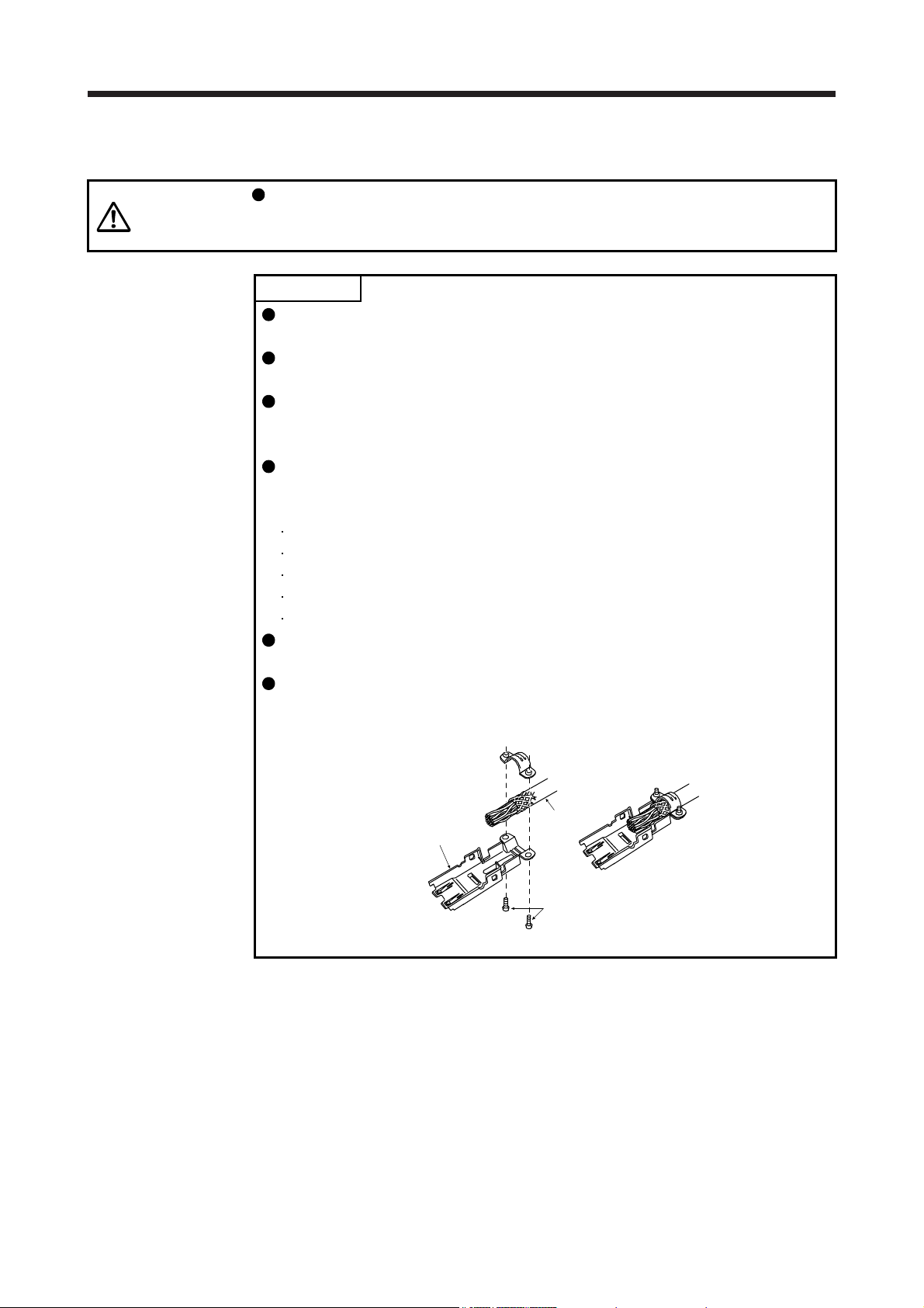
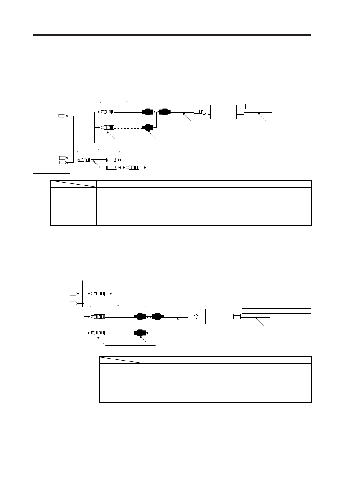
When using a shell kit (36310-3200-008/36310-F200-008) of 3M or connector
set (54599-1019) of Molex, securely connect the external conductor of the
shielded cable to the ground plate and fix it to the connector shell.
Cable
Ground plate
Screw
1 - 1
Page 7
1. LINEAR ENCODER
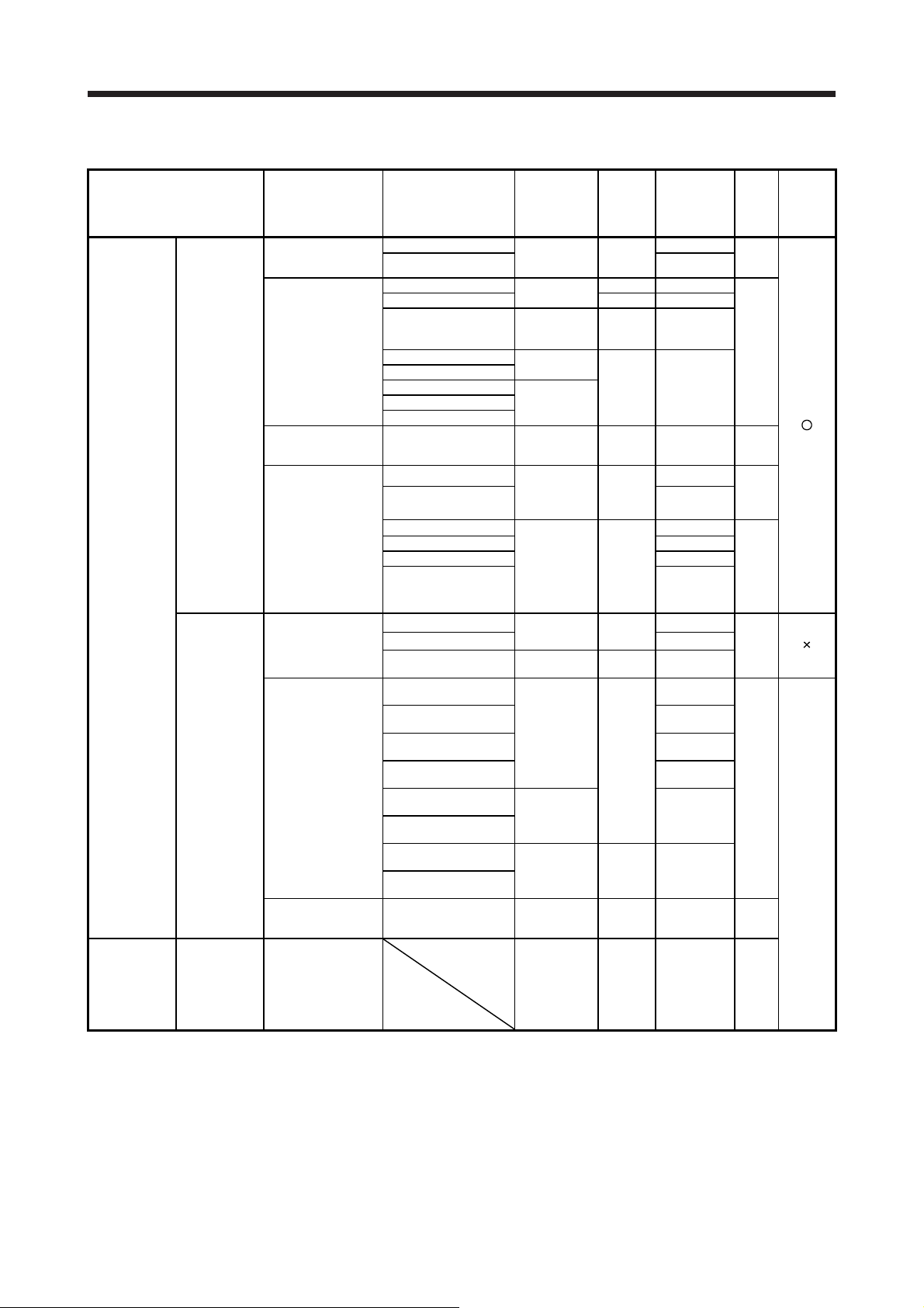
1.1 Compatible linear encoder list
Linear encoder type Manufacturer Model Resolution
SR77
SR87 3040 mm
LC 493M
LC 193M 4240 mm
LIC 4193M
LIC 4195M 28040 mm
LIC 4197M 6040 mm
LIC 4199M 1020 mm
SR75
SR85 3040 mm
SL710 +
PL101-RM/RHM
LIDA 483 + EIB 392M
(/16384)
LIDA 485 + EIB 392M
(/16384)
LIDA 487 + EIB 392M
(/16384)
LIDA 489 + EIB 392M
(/16384)
LIDA 287 + EIB 392M
(/16384)
LIDA 289 + EIB 392M
(/16384)
LIF 481 + EIB 392M
(/4096)
LIP 581 + EIB 392M
(/4096)
Mitsubishi
serial interface
compatibility
A/B/Z-phase
differential
output type
Absolute
position type
Incremental
type
Incremental
type
Magnescale
AT343A
AT543A-SC 2.5 m/s 2200 mm
AT545A-SC
Mitutoyo ST741A
ST742A
ST743A 4.0 m/s 6000 mm
ST744A 0.1 µm
ST748A
Renishaw RESOLUTE RL40M 1 nm/50 nm 4.0 m/s 10000 mm
Heidenhain
Magnescale
Heidenhain
NIDEC SANKYO PSLH041 (Note 6) 0.1 μm 5.0 m/s 2400 mm
Not specified
Rated
speed
(Note 1)
0.05 µm/
0.01 µm
0.05 µm
20 µm/4096
(approx. 0.005
µm)
0.5 µm
0.05 μm/
0.01 μm
0.01 μm 4.0 m/s
0.05 μm/
0.01 μm
0.1 µm 4.0 m/s 100000 mm
20 μm/16384
(approx. 1.22
nm)
200 μm/16384
(approx. 12.2
nm)
4 μm/4096
(approx. 0.977
nm)
0.001 µm to 5
µm
(Note 3)
3.3 m/s
2.0 m/s 3000 mm
2.5 m/s 2200 mm
3.0 m/s
3.3 m/s
4.0 m/s
1.2 m/s
Depends
on the
linear
encoder
Effective
measurement
(maximum)
(Note 2)
2040 mm Two-
2040 mm
3040 mm Two-
2040 mm
3040 mm
to 30040 mm
6040 mm
1020 mm
10000 mm
1020 mm
1440 mm
Depends on
the linear
encoder
length
Commu-
nication
method
(Note 4)
(Note 4)
(Note 4)
method
(Note 5)
wire
type
Two-
wire
type
Two-
wire
type
Four-
wire
type
wire
type/
Four-
wire
type
Two-
wire
type
Four-
wire
type
Two-
wire
type
A/B/Zphase
differe-
ntial
output
Absolute
position
detection
system
Note 1. The indicated value is the rated speed of linear encoder when combined with MR-J4 servo amplifier. It may be different from
the specifications of each manufacturer.
2. The indicated value is the specification value of manufacturer. The encoder cable length between the linear encoder and the
servo amplifier is maximum 30 m.
3. Please select a linear encoder within the range.
4. When using a linear encoder of four-wire type with fully closed loop control, use an MR-J4-(DU)_A_-RJ/MR-J4-(DU)_B_-RJ.
When using a linear encoder of four-wire type with scale measurement function, use an MR-J4-(DU)_B_-RJ.
5. When using a linear encoder of A/B/Z-phase differential output method, use an MR-J4-(DU)_A_-RJ/MR-J4-(DU)_B_-RJ.
6. This can be used with servo amplifier with software version B3 or later.
1 - 2
Page 8
1. LINEAR ENCODER
_
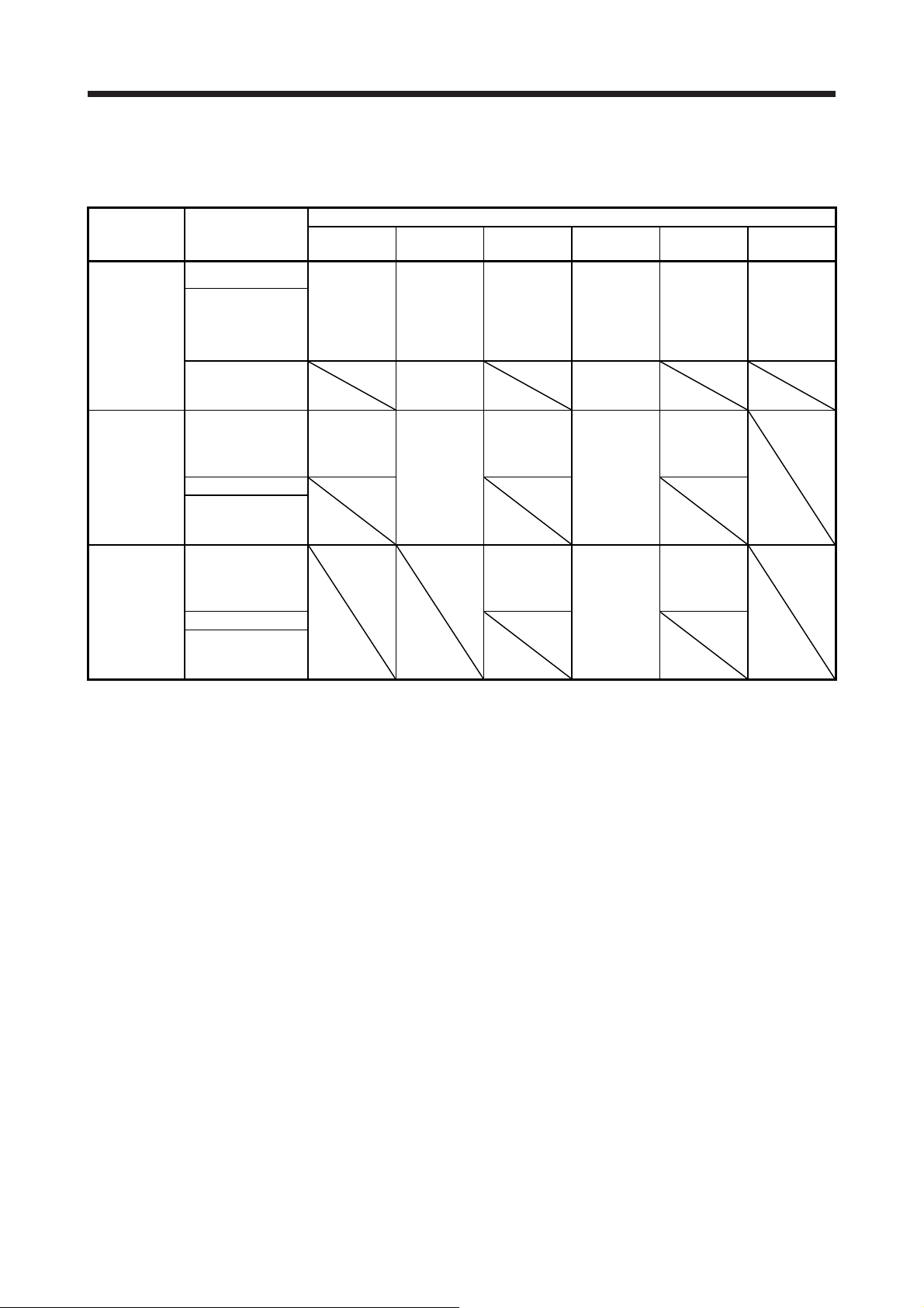
The following table shows connectors of servo amplifiers to connect a linear encoder.
(1) For an MR-J4-_A(1)(-RJ), MR-J4-_B(1)(-RJ), and MR-J4W_-_B servo amplifiers
Operation
mode
Linear servo
motor system
Fully closed
loop system
Scale
measurement
function
External encoder
communication
method
Two-wire type
Four-wire type
A/B/Z-phase
differential output
method
Two-wire type
Four-wire type
A/B/Z-phase
differential output
method
Two-wire type
Four-wire type
A/B/Z-phase
differential output
method
MR-J4-_A
MR-J4-_A1
CN2
(Note 1, 6)
CN2
(Note 2, 3, 6)
MR-J4-_A-RJ
MR-J4-_A1-RJ
CN2
(Note 1)
CN2L
(Note 8)
CN2L
Note 1. The MR-J4THCBL03M branch cable is necessary.
2. The MR-J4FCCBL03M branch cable is necessary.
3. When the communication method of the servo motor encoder is four-wire type, MR-J4-_A(1) and MR-J4-_B(1) cannot be used.
Use an MR-J4-_A(1)-RJ or MR-J4-_B(1)-RJ.
4. When the communication method of the servo motor encoder is four-wire type, MR-J4W2-_B cannot be used. Use an MR-J4-
B-RJ.
5. Supported by servo amplifiers with software version A3 or above.
6. Supported by servo amplifiers with software version A5 or above.
7. Supported by servo amplifiers with software version A8 or above.
8. Connect a thermistor to CN2.
External connection connector
MR-J4-_B
MR-J4-_B1
CN2
(Note 1)
CN2
(Note 2, 3, 5)
CN2
(Note 2, 3, 7)
MR-J4-_B-RJ
MR-J4-_B1-RJ
CN2
(Note 1)
CN2L
(Note 8)
CN2L
CN2L
(Note 7)
MR-J4W2-_B MR-J4W3-_B
CN2A
CN2A
(Note 1)
CN2B
(Note 1)
CN2A
(Note 2, 4, 5)
CN2B
(Note 2, 4, 5)
CN2A
(Note 2, 4, 7)
CN2B
(Note 2, 4, 7)
(Note 1)
CN2B
(Note 1)
CN2C
(Note 1)
1 - 3
Page 9
1. LINEAR ENCODER
(2) For an MR-J4-_A4(-RJ) and MR-J4-_B4(-RJ) servo amplifiers
Operation
mode
Linear servo
motor system
Fully closed
loop system
Scale
measurement
function
External encoder
communication
method
Two-wire type
Four-wire type
A/B/Z-phase
differential output
method
Two-wire type
Four-wire type
A/B/Z-phase
differential output
method
Two-wire type
Four-wire type
A/B/Z-phase
differential output
method
MR-J4-_A4 MR-J4-_A4-RJ MR-J4-_B4 MR-J4-_B4-RJ
CN2
(Note 1)
CN2
(Note 2, 3)
Note 1. The MR-J4THCBL03M branch cable is necessary.
2. The MR-J4FCCBL03M branch cable is necessary.
3. When the communication method of the servo motor encoder is four-wire type, MR-J4-_A4 and MR-J4-_B4 cannot be used.
Use an MR-J4-_A4-RJ or MR-J4-_B4-RJ.
4. Supported by servo amplifiers with software version A8 or above.
5. Connect a thermistor to CN2.
(3) For an MR-J4-DU_A_(-RJ) and MR-J4-DU_B_(-RJ) drive units
Operation
mode
Fully closed
loop system
Scale
measurement
function
External encoder
communication
method
Two-wire type CN2 (Note 1, 2)
Four-wire type
A/B/Z-phase
differential output
method
Two-wire type
Four-wire type
A/B/Z-phase
differential output
method
MR-J4-DU_A_ MR-J4-DU_A_-RJ MR-J4-DU_B_ MR-J4-DU_B_-RJ
Note 1. The MR-J4FCCBL03M branch cable is necessary.
2. When the communication method of the servo motor encoder is four-wire type, MR-J4-DU_A_ and MR-J4-DU_B_ cannot be
used. Use an MR-J4-DU_A_-RJ or MR-J4-DU_B_-RJ.
External connection connector
CN2
(Note 1)
CN2L
(Note 5)
CN2L
External connection connector
CN2L
CN2
(Note 1)
CN2
(Note 2, 3)
CN2
(Note 2, 3, 4)
CN2 (Note 1, 2)
CN2 (Note 1, 2)
CN2
(Note 1)
CN2L
(Note 5)
CN2L
CN2L
(Note 4)
CN2L
CN2L
1 - 4
Page 10
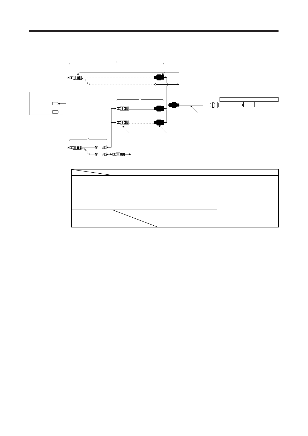
1. LINEAR ENCODER
1.2 Linear encoder manufactured by Mitutoyo (absolute type)
POINT
When the absolute position detection system is configured, the absolute position
battery is not required.
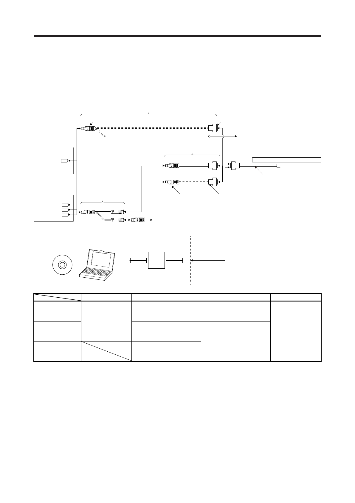
1.2.1 AT343A
(1) Cable composition
Prepare a cable based on the following configuration diagram.
(a) For the linear servo motor
1) MR-J4-_A_, MR-J4-_B_, or MR-J4W_-_B servo amplifier
Encoder cable 2
MR-J4-_A_
or
MR-J4-_B_
servo amplifier
CN2
Encoder cable 1
1)
5)
Thermistor of linear servo motor
Linear encoder
AT343A
3)
MR-J4W_-_B
servo amplifier
CN2A
CN2B
(Note 1)
CN2C
Branch cable
CN2 4) SCALE
THMor(Note 3)
Branch cable Encoder cable Output cable
When using an
optional encoder
cable
When fabricating
the encoder cable
When not using a
branch cable
Note 1. The connection to CN2C is for the MR-J4 3-axis servo amplifier. MR-J4 2-axis servo amplifier does not
have CN2C.
2. It should be prepared by the customer.
3. For connectors for thermistor signals, change how to connect depending on the customer's system.
4) MR-J4THCBL03M
5) Connector set MR-ECNM
Thermistor of linear servo motor
1) MR-EKCBL_M-H
(Refer to section
2.4.)
2) Connector set MR-ECNM
2)
2 m/5 m (Refer to section
2.1.)
(Refer to (2) (a) of this
section.)
(Refer to (2) (b) of this
section.)
3) Options manufactured by
Mitutoyo (Note 2)
Part No.09BAA598A: 0.2 m
Part No.09BAA598B: 2 m
Part No.09BAA598C: 3 m
1 - 5
Page 11
1. LINEAR ENCODER
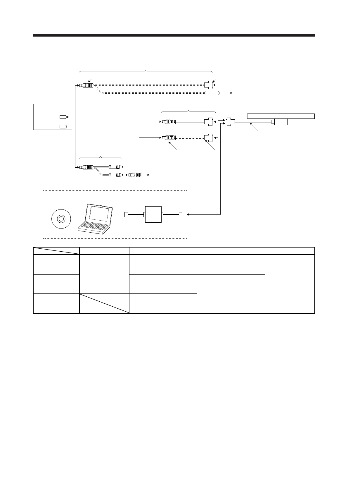
2) MR-J4-_A_-RJ or MR-J4-_B_-RJ servo amplifier
Encoder cable 2
MR-J4-_A_-RJ
or
MR-J4-_B_-RJ
servo amplifier
CN2
CN2L
5)
Thermistor of linear servo motor
Encoder cable 1
1)
Linear encoder
AT343A
3)
Branch cable
CN2 4) SCALE
THM (Note 2)
Branch cable Encoder cable Output cable
When using an
optional encoder
cable
When fabricating
the encoder cable
When not using a
branch cable
Note 1. It should be prepared by the customer.
2. For connectors for thermistor signals, change how to connect depending on the customer's system.
4) MR-J4THCBL03M
5) Connector set MR-ECNM
Thermistor of linear servo motor
1) MR-EKCBL_M-H
(Refer to section
2.4.)
2) Connector set MR-ECNM
2)
2 m/5 m (Refer to section
2.1.)
(Refer to (2) (a) of this
section.)
(Refer to (2) (b) of this
section.)
3) Options manufactured by
Mitutoyo (Note 1)
Part No.09BAA598A: 0.2 m
Part No.09BAA598B: 2 m
Part No.09BAA598C: 3 m
1 - 6
Page 12

1. LINEAR ENCODER
(b) For the fully closed loop system and scale measurement function
1) MR-J4-_A_/MR-J4-_B_/MR-J4W2-_B servo amplifier or MR-J4-DU_A_/MR-J4-DU_B_ drive unit
MR-J4-_A_/
MR-J4-_B_
servo amplifier
or
MR-J4-DU_A_/
MR-J4-DU_B_
drive unit
CN2
Encoder cable 1
1)
Linear encoder
AT343A
or
MR-J4W2-_B
servo amplifier
CN2A
CN2B
3)
Branch cable
CN2 4) SCALE
MOTOR
Branch cable Encoder cable Output cable
When using an
optional encoder
cable
When fabricating
the encoder cable
Note. It should be prepared by the customer.
4) MR-J4FCCBL03M
Encoder of rotary servo motor
1) MR-EKCBL_M-H
(Refer to section
2.5.)
2) Connector set MR-ECNM
2)
2 m/5 m (Refer to section
2.1.)
(Refer to (2) (a) of this
section.)
3) Options manufactured by
Mitutoyo (Note)
Part No.09BAA598A: 0.2 m
Part No.09BAA598B: 2 m
Part No.09BAA598C: 3 m
2) MR-J4-_A_-RJ/MR-J4-_B_-RJ servo amplifier or MR-J4-DU_A_-RJ/MR-J4-DU_B_-RJ drive unit
MR-J4-_A_-RJ/
MR-J4-_B_-RJ
servo amplifier
or
MR-J4-DU_A_-RJ/
MR-J4-DU_B_-RJ
drive unit
CN2
CN2L
Encoder cable Output cable
When using an
optional encoder
cable
When fabricating
the encoder cable
Encoder of rotary servo motor
Encoder cable 1
1)
1) MR-EKCBL_M-H
2) Connector set MR-ECNM
3)
2)
2 m/5 m (Refer to section
2.1.)
(Refer to (2) (a) of this
section.)
Linear encoder
AT343A
3) Options manufactured by
Mitutoyo (Note)
Part No.09BAA598A: 0.2 m
Part No.09BAA598B: 2 m
Part No.09BAA598C: 3 m
Note. It should be prepared by the customer.
1 - 7
Page 13

1. LINEAR ENCODER
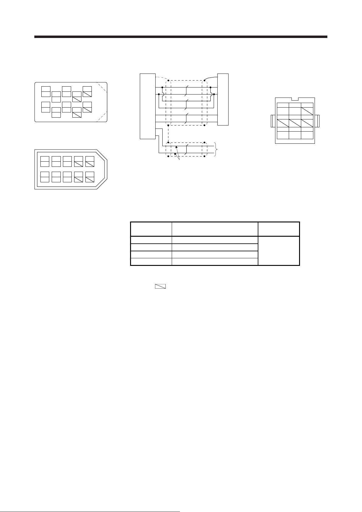
(2) Production of encoder cable
Produce the encoder cable using MR-ECNM as shown below. The encoder cable can be produced as
the length of maximum 30 m.
(a) Encoder cable 1
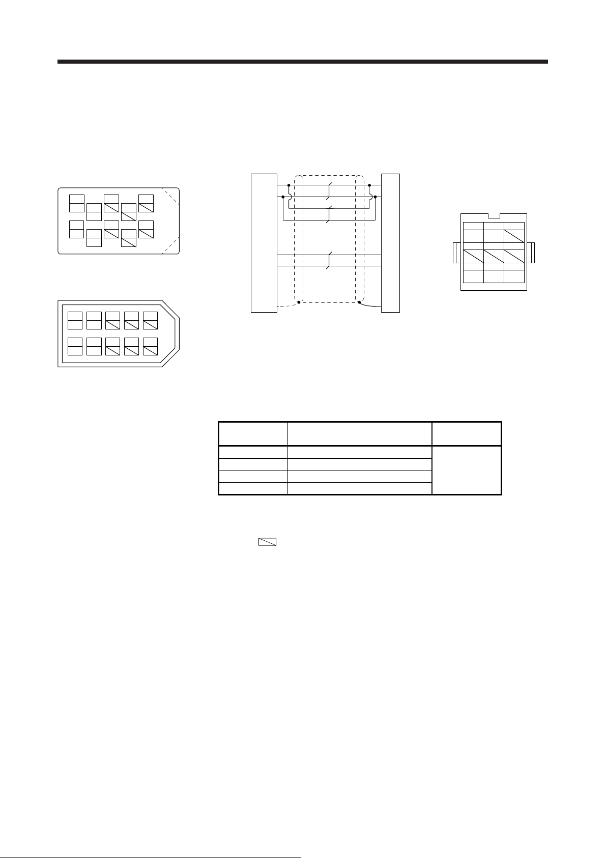
Receptacle: 36210-0100PL
Shell kit: 36310-3200-008
(3M)
2
LG 8
1
P5
View seen from wiring side. (Note 3)
Connector set: 54599-1019
(Molex)
2
LG
1P5379
6
4
MRR
5
37
MR
or
4
MRR
5
MR
(Note 2)
10
9
(Note 2)
8610
(Note 2)
Servo amplifier side Linear encoder side
P5
LG
MR
MRR34
Plate
SD
1
2
(Note 1)
P5
7
LG
8
RQ
1
2
/RQ
FG
9
Housing: 1-172161-9
Connector pin: 170359-1
(TE Connectivity or
equivalent)
Cable clamp: MTI-0002
(Toa Electric Industry)
123
RQ
View seen from wiring side.
/RQ
456
789
P5
LG FG
View seen from wiring side. (Note 3)
Note 1. We recommend the following specifications encoder cables.
Wiring length
to 5 m 1-pair
to 10 m 2-pair
to 20 m 3-pair
to 30 m 5-pair
Number of LG and P5 connections
(when the output cable is 3 m or less)
2. For the CN2L connector, signals of pin 3 and pin 4 will be as follows.
Pin 3: MR2 Pin 4: MRR2
3. Do not connect anything to the pins shown as
any other pin, the servo amplifier cannot operate normally. Referring POINT of chapter 1, securely connect the external
conductor of the shielded cable to the ground plate and fix it to the connector shell.
. Especially, pin 10 is for manufacturer adjustment. If it is connected with
Cable size
AWG 22
1 - 8
Page 14
1. LINEAR ENCODER
(b) Encoder cable 2
Receptacle: 36210-0100PL
Shell kit: 36310-3200-008
(3M)
2
LG 8
1
P5
View seen from wiring side. (Note 3)
Connector set: 54599-1019
(Molex)
2
LG
1P5379
View seen from wiring side. (Note 3)
6
THM2
4
MRR
5
THM1
37
MR
4
THM2
MRR
5
THM1
MR
10
or
8610
9
Servo amplifier side Linear encoder side
SD Plate 9 FG
(Note 1)
AWG 24 to 20
P5
LG
MR
MRR34
THM1
THM256
1
2
P5
7
LG
8
1
RQ
2
/RQ
Thermistor of
linear servo
motor (Note 2)
Note 1. We recommend the following specifications encoder cables.
Wiring length
to 5 m 1-pair
to 10 m 2-pair
to 20 m 3-pair
to 30 m 5-pair
Number of LG and P5 connections
(when the output cable is 3 m or less)
2. For wiring to the thermistor of the linear servo motor, refer to "Linear Servo Motor Instruction Manual".
3. Do not connect anything to the pins shown as
any other pin, the servo amplifier cannot operate normally. Referring POINT of chapter 1, securely connect the external
conductor of the shielded cable to the ground plate and fix it to the connector shell.
. Especially, pin 10 is for manufacturer adjustment. If it is connected with
Housing: 1-172161-9
Connector pin: 170359-1
(TE Connectivity or
equivalent)
Cable clamp: MTI-0002
(Toa Electric Industry)
View seen from wiring side.
Cable size
AWG 22
123
RQ
/RQ
456
789
P5
LG FG
1 - 9
Page 15
1. LINEAR ENCODER
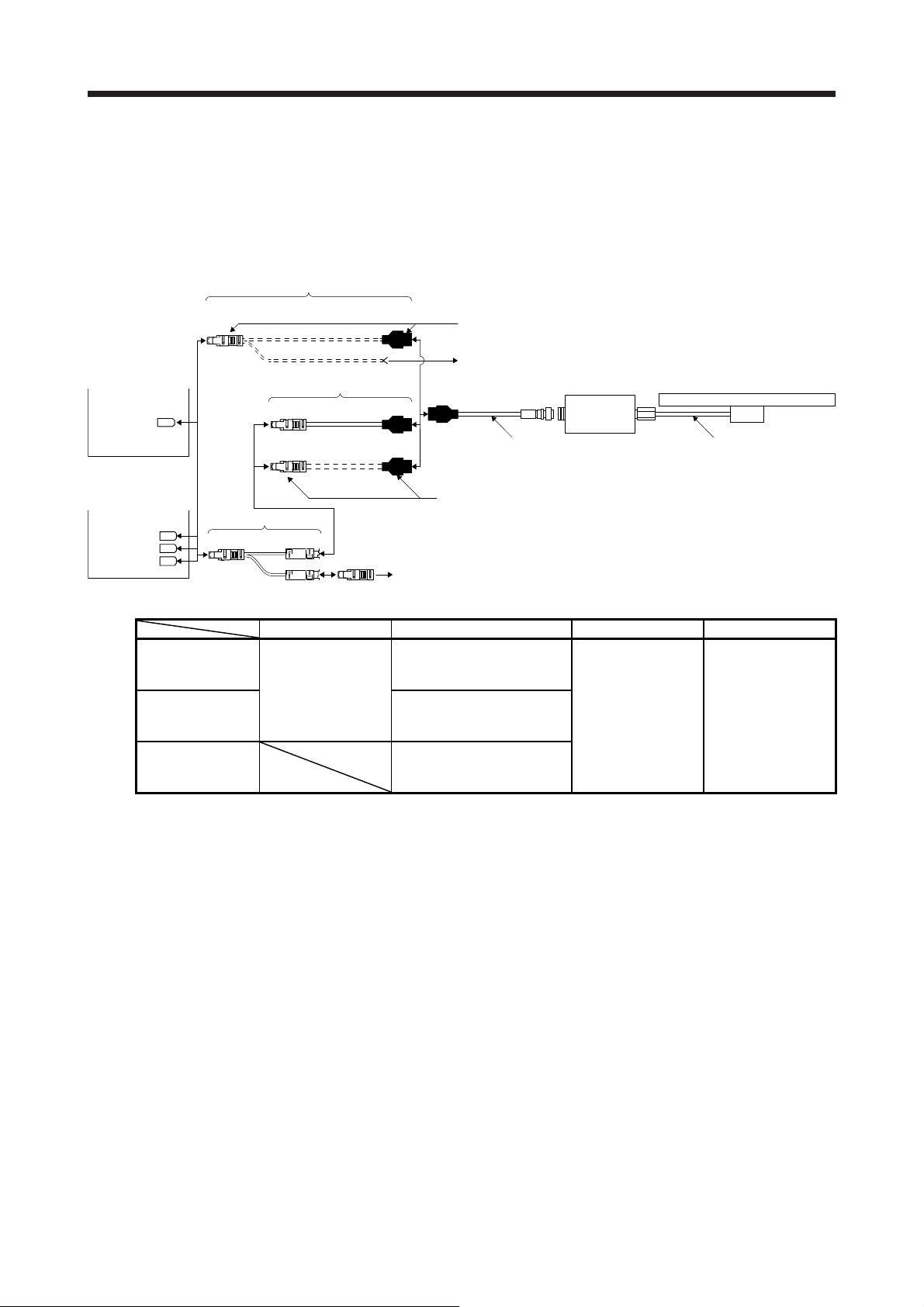
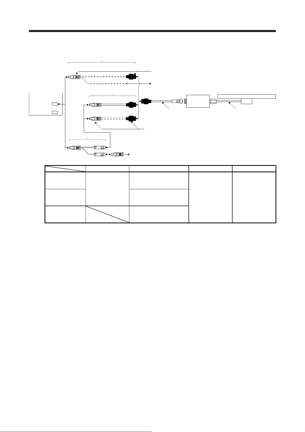
1.2.2 AT543A-SC/AT545A-SC
(1) Cable composition
Prepare a cable based on the following configuration diagram.
(a) For the linear servo motor
1) MR-J4-_A_, MR-J4-_B_, or MR-J4W_-_B servo amplifier
Encoder cable 2
4)
MR-J4-_A_
or
MR-J4-_B_
servo amplifier
CN2
Encoder cable 1
1)
Thermistor of linear servo motor
Linear encoder
AT543A-SC or AT545A-SC
or
MR-J4W_-_B
servo amplifier
CN2A
CN2B
(Note 1)
CN2C
Note 1. The connection to CN2C is for the MR-J4 3-axis servo amplifier. MR-J4 2-axis servo amplifier does not have CN2C.
2. For connectors for thermistor signals, change how to connect depending on the customer's system.
Output cable
2)
Branch cable
CN2 3) SCALE
THM
(Note 2)
Branch cable Encoder cable Output cable Head cable
When using an
optional encoder
cable
When fabricating
the encoder cable
When not using a
branch cable
3) MR-J4THCBL03M
(Refer to section
2.4.)
4) Connector set MR-ECNM
Thermistor of linear servo motor
1) MR-EKCBL_M-H
2 m/5 m (Refer to section
2.1.)
2) Connector set MR-ECNM
(Refer to (2) (a) of this
section.)
(Refer to (2) (b) of this
section.)
Accessories for linear
encoder
Cable length: 3 m
Head cable
Accessories for linear
encoder
Cable length: 2 m
1 - 10
Page 16
1. LINEAR ENCODER
2) MR-J4-_A_-RJ or MR-J4-_B_-RJ servo amplifier
Encoder cable 2
MR-J4-_A_-RJ
or
MR-J4-_B_-RJ
servo amplifier
CN2
CN2L
Branch cable
CN2 3) SCALE
Encoder cable 1
4)
Thermistor of linear servo motor
1)
Output cable
2)
Linear encoder
AT543A-SC or AT545A-SC
Head cable
THM (Note)
Branch cable Encoder cable Output cable Head cable
When using an
optional encoder
cable
When fabricating
the encoder cable
When not using a
branch cable
3) MR-J4THCBL03M
(Refer to section
2.4.)
4) Connector set MR-ECNM
Thermistor of linear servo motor
1) MR-EKCBL_M-H
2 m/5 m (Refer to section
2.1.)
2) Connector set MR-ECNM
(Refer to (2) (a) of this
section.)
(Refer to (2) (b) of this
section.)
Accessories for linear
encoder
Cable length: 3 m
Accessories for linear
encoder
Cable length: 2 m
Note. For connectors for thermistor signals, change how to connect depending on the customer's system.
1 - 11
Page 17
1. LINEAR ENCODER
/
(b) For the fully closed loop system and scale measurement function
1) MR-J4-_A_/MR-J4-_B_/MR-J4W2-_B servo amplifier or MR-J4-DU_A_/MR-J4-DU_B_ drive unit
MR-J4-_A_/
MR-J4-_B_
servo amplifier
or
MR-J4-DU_A_/
MR-J4-DU_B_
drive unit
CN2
Encoder cable 1
1)
Linear encoder
AT543A-SC or AT545A-SC
or
MR-J4W2-_B
servo amplifier
CN2A
CN2B
Branch cable Encoder cable Output cable Head cable
When using an
optional encoder
cable
When fabricating
the encoder cable
2) MR-J4-_A_-RJ/MR-J4-_B_-RJ servo amplifier or MR-J4-DU_A_-RJ/MR-J4-DU_B_-RJ drive unit
MR-J4-_A_-RJ
MR-J4-_B_-RJ
servo amplifier
MR-J4-DU_A_-RJ/
MR-J4-DU_B_-RJ
drive unit
CN2 3) SCALE
or
CN2
CN2L
Branch cable
MOTOR
3) MR-J4FCCBL03M
(Refer to section
2.5.)
Encoder of rotary servo motor
Encoder cable 1
Output cable
2)
Encoder of rotary servo motor
1) MR-EKCBL_M-H
2 m/5 m (Refer to section
2.1.)
2) Connector set MR-ECNM
(Refer to (2) (a) of this
section.)
1)
Accessories for linear
encoder
Cable length: 3 m
Linear encoder
AT543A-SC or AT545A-SC
Head cable
Accessories for linear
encoder
Cable length: 2 m
Output cable
2)
Encoder cable Output cable Head cable
When using an
optional encoder
cable
When fabricating
the encoder cable
1) MR-EKCBL_M-H
2 m/5 m (Refer to section
2.1.)
2) Connector set MR-ECNM
(Refer to (2) (a) of this
section.)
Accessories for linear
encoder
Cable length: 3 m
Head cable
Accessories for linear
encoder
Cable length: 2 m
1 - 12
Page 18
1. LINEAR ENCODER
(2) Production of encoder cable
Produce the encoder cable using MR-ECNM as shown below. The encoder cable can be produced as
the length of maximum 30 m.
(a) Encoder cable 1
Receptacle: 36210-0100PL
Shell kit: 36310-3200-008
(3M) (Note 2)
2
LG 8
1
P5
View seen from wiring side. (Note 3)
Connector set: 54599-1019
(Molex)
2
LG
1P5379
6
4
MRR
5
37
MR
4
MRR
5
MR
10
or
8610
9
(Note 2)
(Note 2)
Servo amplifier side Linear encoder side
P5
LG
MR
MRR34
Plate
SD
1
2
(Note 1)
7
8
1
2
9
P5 (+5V)
LG (0V)
RQ
/RQ
FG
Housing: 1-172161-9
Connector pin: 170359-1
(TE Connectivity or
equivalent)
Cable clamp: MTI-0002
(Toa Electric Industry)
123
RQ
View seen from wiring side.
/RQ
456
789
P5
(+5 V)LG(0 V)
FG
View seen from wiring side. (Note 3)
Note 1. We recommend the following specifications encoder cables.
Wiring length
to 5 m 1-pair
to 10 m 2-pair
to 20 m 4-pair
to 30 m 5-pair
Number of LG and P5 connections
(when the output cable is 3 m or less)
2. For the CN2L connector, signals of pin 3 and pin 4 will be as follows.
Pin 3: MR2 Pin 4: MRR2
3. Do not connect anything to the pins shown as
any other pin, the servo amplifier cannot operate normally. Referring POINT of chapter 1, securely connect the external
conductor of the shielded cable to the ground plate and fix it to the connector shell.
. Especially, pin 10 is for manufacturer adjustment. If it is connected with
Cable size
AWG 22
1 - 13
Page 19

1. LINEAR ENCODER
(b) Encoder cable 2
Receptacle: 36210-0100PL
Shell kit: 36310-3200-008
(3M)
2
LG 8
1
P5
6
THM2
4
MRR
5
THM1
37
10
9
MR
View seen from wiring side. (Note 3)
or
Servo amplifier side Linear encoder side
SD Plate 9 FG
P5
LG
1
2
(Note 1)
MR
MRR34
THM1
THM256
P5 (+5V)
7
P5
LG (0V)
8LG
1
RQ
2
/RQ
Connector set: 54599-1019
(Molex)
2
4
MRR
LG
1P5379
MR
8610
THM2
5
THM1
AWG 24 to 20
Thermistor of
linear servo
motor (Note 2)
View seen from wiring side. (Note 3)
Note 1. We recommend the following specifications encoder cables.
Wiring length
to 5 m 1-pair
to 10 m 2-pair
to 20 m 4-pair
to 30 m 5-pair
Number of LG and P5 connections
(when the output cable is 3 m or less)
2. For wiring to the thermistor of the linear servo motor, refer to "Linear Servo Motor Instruction Manual".
3. Do not connect anything to the pins shown as
any other pin, the servo amplifier cannot operate normally. Referring POINT of chapter 1, securely connect the external
conductor of the shielded cable to the ground plate and fix it to the connector shell.
. Especially, pin 10 is for manufacturer adjustment. If it is connected with
Housing: 1-172161-9
Connector pin: 170359-1
(TE Connectivity or
equivalent)
Cable clamp: MTI-0002
(Toa Electric Industry)
View seen from wiring side.
Cable size
AWG 22
1
23
RQ
/RQ
456
789
P5
LG
(0 V)
FG
(+5 V)
1 - 14
Page 20
1. LINEAR ENCODER
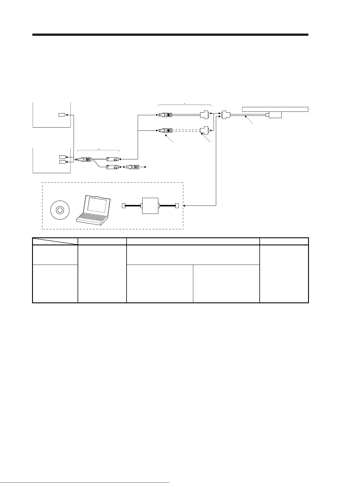
1.2.3 ST741A/ST742A/ST743A/ST744A
(1) Cable composition
Prepare a cable based on the following configuration diagram.
(a) For the linear servo motor
1) MR-J4-_A_, MR-J4-_B_, or MR-J4W_-_B servo amplifier
Encoder cable 2
MR-J4-_A_
or
MR-J4-_B_
servo amplifier
CN2
Encoder cable 1
3)5)
Thermistor of linear servo motor
Linear encoder
ST741A, ST742A, ST743A,
1)
ST744A or ST748A
or
MR-J4W_-_B
servo amplifier
Branch cable
CN2A
CN2B
CN2C
(Note 1)
For the signal adjustment and confirmation, connect the following equipments. (Note 3)
Software for
signal adjustment
Branch cable Encoder cable Head cable
When using an
optional encoder
cable
When fabricating
the encoder cable
When not using a
branch cable
4) SCALECN2
THM (Note 4)
Personal
computer
4) MR-J4THCBL03M
(Refer to section
2.4.)
5) Connector set MR-J3CN2
1) Options manufactured by Mitutoyo (Note 2)
2) Connector set MR-J3CN2
Thermistor of linear servo motor
Conversion unit
Part No.06ACF117A: 5 m
Part No.06ACF117B: 10 m
(Refer to (2) (a) of this
section.)
(Refer to (2) (b) of this
section.)
2) 3)
3) Junction connector (Note 2)
D-SUB (female) 15 pin
Shell: HDAB-15S
Plug case: HDA-CTH
(manufactured by Hirose
Electric)
Head cable
Accessories for linear
encoder
Cable length: 1 m
Note 1. The connection to CN2C is for the MR-J4 3-axis servo amplifier. MR-J4 2-axis servo amplifier does not have CN2C.
2. It should be prepared by the customer.
3. When mounting ST741A, ST742A, ST743A, ST744A or ST748A, a personal computer (with RS-232C port) for the signal
adjustment and confirmation, and a software and conversion unit for signal adjustment are required. For details, contact
Mitutoyo.
4. For connectors for thermistor signals, change how to connect depending on the customer's system.
1 - 15
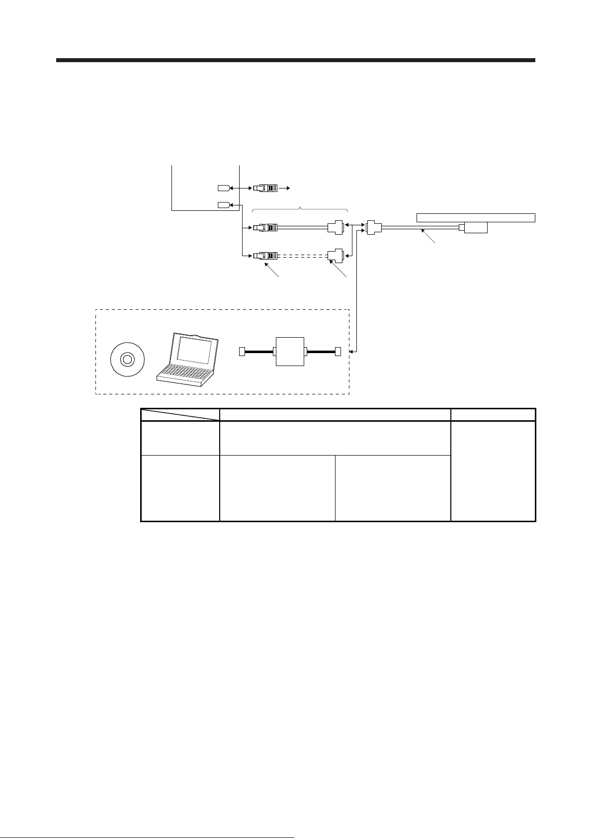
Page 21
1. LINEAR ENCODER
2) MR-J4-_A_-RJ or MR-J4-_B_-RJ servo amplifier
MR-J4-_A_-RJ
or
MR-J4-_B_-RJ
servo amplifier
CN2
CN2L
Encoder cable 2
Encoder cable 1
1)
3)5)
Thermistor of linear servo motor
Linear encoder
ST741A, ST742A, ST743A,
ST744A, or ST748A
Head cable
Branch cable
CN2
For the signal adjustment and confirmation, connect the following equipments. (Note 2)
Software for
signal adjustment
Branch cable Encoder cable Head cable
When using an
optional encoder
cable
When fabricating
the encoder cable
When not using a
branch cable
4) SCALE
THM (Note 3)
Personal
computer
4) MR-J4THCBL03M
(Refer to section
2.4.)
5) Connector set MR-J3CN2
1) Options manufactured by Mitutoyo (Note 1)
2) Connector set MR-J3CN2
Thermistor of linear servo motor
Conversion unit
Part No.06ACF117A: 5 m
Part No.06ACF117B: 10 m
(Refer to (2) (a) of this
section.)
(Refer to (2) (b) of this
section.)
2)
3)
3) Junction connector (Note 1)
D-SUB15 pin (female)
Shell: HDAB-15S
Plug case: HDA-CTH
(Hirose Electric)
Accessories for linear
encoder
Cable length: 1 m
Note 1. It should be prepared by the customer.
2. When mounting ST741A, ST742A, ST743A, ST744A, or ST748A, a personal computer (with RS-232C port) for the signal
adjustment and confirmation, and a software and conversion unit for signal adjustment are required. For details, contact
Mitutoyo.
3. For connectors for thermistor signals, change how to connect depending on the customer's system.
1 - 16
Page 22
1. LINEAR ENCODER
(b) For the fully closed loop system and scale measurement function
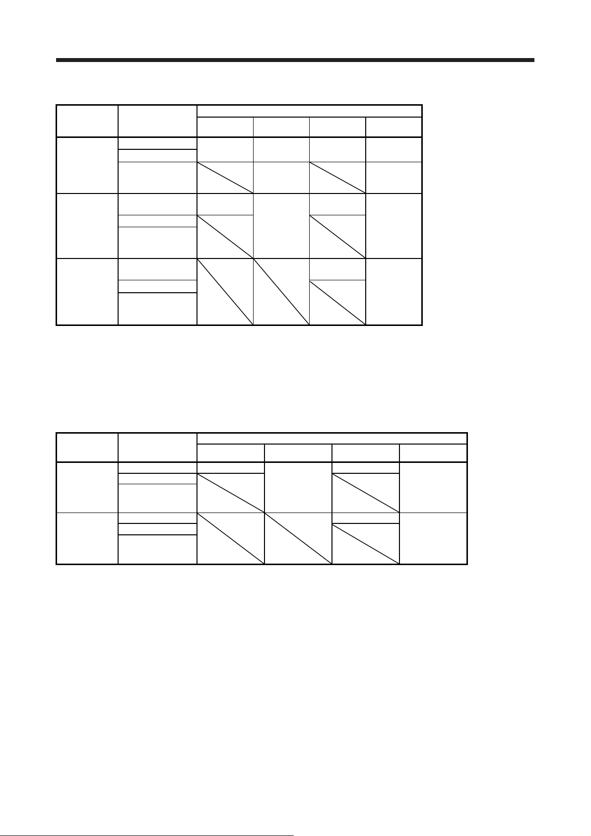
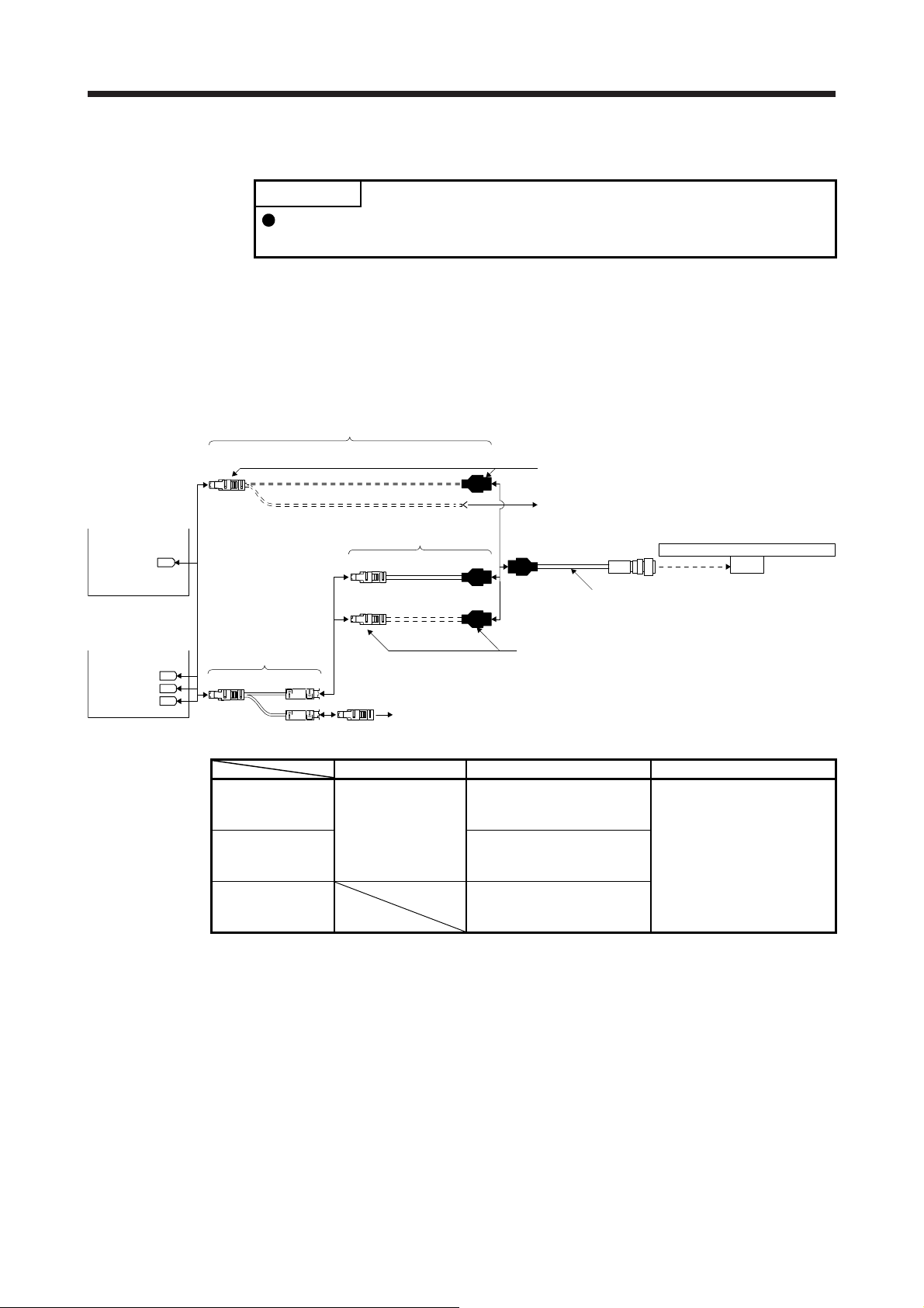
1) MR-J4-_A_/MR-J4-_B_/MR-J4W2-_B servo amplifier or MR-J4-DU_A_/MR-J4-DU_B_ drive unit
MR-J4-_A_/
MR-J4-_B_
servo amplifier
or
MR-J4-DU_A_/
MR-J4-DU_B_
drive unit
CN2
or
MR-J4W2-_B
servo amplifier
CN2A
CN2B
For the signal adjustment and confirmation, connect the following equipments. (Note 2)
Software for
signal adjustment
Branch cable
CN2 4) SCALE
MOTOR
Personal
computer
Encoder of rotary servo motor
Conversion unit
Encoder cable 1
1)
2) 3)
Linear encoder
ST741A, ST742A, ST743A,
ST744A or ST748A
Head cable
Branch cable Encoder cable Head cable
When using an
optional encoder
cable
When fabricating
the encoder cable
4) MR-J4FCCBL03M
(Refer to section
2.5.)
1) Options manufactured by Mitutoyo (Note 1)
Part No.06ACF117A: 5 m
Part No.06ACF117B: 10 m
2) Connector set MR-J3CN2
(Refer to (2) (a) of this
section.)
3) Junction connector (Note 1)
D-SUB (female) 15 Pin
shell: HDAB-15S
Plug case: HDA-CTH
(manufactured by Hirose
Electric)
Accessories for linear
encoder
Cable length: 1 m
Note 1. It should be prepared by the customer.
2. When mounting ST741A, ST742A, ST743A, ST744A or ST748A, a personal computer (with RS-232C port) for the signal
adjustment and confirmation, and a software and conversion unit for signal adjustment are required. For details, contact
Mitutoyo.
1 - 17
Page 23
1. LINEAR ENCODER
/
2) MR-J4-_A_-RJ/MR-J4-_B_-RJ servo amplifier or MR-J4-DU_A_-RJ/MR-J4-DU_B_-RJ drive unit
MR-J4-_A_-RJ
MR-J4-_B_-RJ
servo amplifier
MR-J4-DU_A_-RJ/
MR-J4-DU_B_-RJ
drive unit
or
CN2
CN2L
For the signal adjustment and confirmation, connect the following
equipments. (Note 2)
Software for
signal adjustment
Personal
computer
Encoder cable Head cable
When using an
optional encoder
cable
When fabricating
the encoder cable
1) Options manufactured by Mitutoyo (Note 1)
Part No.06ACF117A: 5 m
Part No.06ACF117B: 10 m
2) Connector set MR-J3CN2
(Refer to (2) (a) of this
section.)
Encoder of rotary servo motor
Encoder cable 1
1)
2)
Conversion unit
Linear encoder
ST741A, ST742A, ST743A,
ST744A or ST748A
Head cable
3)
3) Junction connector (Note 1)
D-SUB (female) 15 pin
Shell: HDAB-15S
Plug case: HDA-CTH
(manufactured by Hirose
Electric)
Accessories for linear
encoder
Cable length: 1 m
Note 1. It should be prepared by the customer.
2. When mounting ST741A, ST742A, ST743A or ST744A, a personal computer (with RS-232C port) for
the signal adjustment and confirmation, and a software and conversion unit for signal adjustment are
required. For details, contact Mitutoyo.
1 - 18
Page 24

1. LINEAR ENCODER
)
(2) Production of encoder cable
Produce the load side encoder cable using MR-J3CN2 or a junction connector as shown below. The
encoder cable can be produced as the length of maximum 30 m.
(a) Encoder cable 1
Connector set (option
MR-J3CN2
Receptacle: 36210-0100PL
Shell kit: 36310-3200-008
(3M) (Note 2)
2
LG 8
1
P5
View seen from wiring side. (Note 3)
Connector set: 54599-1019
(Molex)
2
LG
1P5379
6
4
MRR
37
MR
4
MRR
MR
10
5
or
8610
5
9
(Note 2)
Servo amplifier side Linear encoder side
(Note 1)
(Note 2)
P5
LG12
MR
MRR34
Plate
SD
P5
3
LG
1
4
P5
2LG
7
RQ
8 /RQ
FG
15
Shell: HDAB-15S
Shield cover: HDA-CTH
(Hirose Electric or equivalent)
42
3
P5
LG
LG
10
9
View seen from wiring side.
5
P5
11 12 13 14 15
RQ
861
7
/RQ
FG
View seen from wiring side. (Note 3)
Note 1. We recommend the following specifications encoder cables.
Wiring length
to 10 m 1-pair
to 20 m 2-pair
to 30 m 3-pair
Number of LG and P5 connections
(when the head cable is 1 m or less)
2. For the CN2L connector, signals of pin 3 and pin 4 will be as follows.
Pin 3: MR2 Pin 4: MRR2
3. Do not connect anything to the pins shown as
. Especially, pin 10 is for manufacturer adjustment. If it is connected with
any other pin, the servo amplifier cannot operate normally. Referring POINT of chapter 1, securely connect the external
conductor of the shielded cable to the ground plate and fix it to the connector shell.
Cable size
AWG 22
1 - 19
Page 25

1. LINEAR ENCODER
)
T
T
(b) Encoder cable 2
Connector set (option
MR-J3CN2
Receptacle: 36210-0100PL
Shell kit: 36310-3200-008
(3M)
2
LG 8
1
P5
View seen from wiring side. (Note 3)
Connector set: 54599-1019
(Molex)
2
LG
1P5379
View seen from wiring side. (Note 3)
6
THM2
4
MRR
5
THM1
37
MR
or
THM2
THM1
5
8610
MRR
MR
4
10
9
Servo amplifier side Linear encoder side
SD
P5
LG
Plate
1
2
(Note 1)
15 FG
3
P5
1 LG
42P5
LG
MR
MRR34
7
RQ
8 /RQ
HM1
HM256
Thermistor of
linear servo
AWG 24 to 20
motor (Note 2)
Note 1. We recommend the following specifications encoder cables.
Wiring length
to 10 m 1-pair
to 20 m 2-pair
to 30 m 3-pair
Number of LG and P5 connections
(when the head cable is 1 m or less)
2. For wiring to the thermistor of the linear servo motor, refer to "Linear Servo Motor Instruction Manual".
3. Do not connect anything to the pins shown as
. Especially, pin 10 is for manufacturer adjustment. If it is connected with
any other pin, the servo amplifier cannot operate normally. Referring POINT of chapter 1, securely connect the external
conductor of the shielded cable to the ground plate and fix it to the connector shell.
Shell: HDAB-15S
Shield cover: HDA-CTH
(Hirose Electric or equivalent)
3
LG
LG
P5
9
10
11 12 13 14 15
View seen from wiring side.
Cable size
AWG 22
P5
42
5
7
RQ
861
/RQ
FG
1 - 20
Page 26

1. LINEAR ENCODER
1.3 Linear encoder manufactured by Heidenhain
POINT
When the absolute position detection system is configured, the absolute position
battery is not required.
1.3.1 LC 493M/LC 193M (absolute type)
POINT
This linear encoder is of four-wire type. When using this linear encoder, change
the parameter to select the four-wire type. For changing parameters, refer to
each servo amplifier instruction manual.
When using a linear encoder of four-wire type with fully closed loop control, use
an MR-J4-(DU)_A_-RJ/MR-J4-(DU)_B_-RJ.
When using a linear encoder of four-wire type with scale measurement function,
use an MR-J4-(DU)_B_-RJ.
1 - 21
Page 27

1. LINEAR ENCODER
(1) Cable composition
Prepare a cable based on the following configuration diagram.
(a) For the linear servo motor
1) MR-J4-_A_, MR-J4-_B_, or MR-J4W_-_B servo amplifier
Encoder cable 2
6)
MR-J4-_A_
or
MR-J4-_B_
servo amplifier
Encoder cable 1
1)
2)
Thermistor of linear servo motor
MR-J4W_-_B
servo amplifier
CN2A
CN2B
(Note 1)
CN2C
CN2
Branch cable
CN2 5) SCALE
THMor(Note 3)
3)
Thermistor of linear servo motor
4) Output cable
3)
Linear encoder
LC 493M or LC 193M
Branch cable Encoder cable
When using an
optional encoder
cable
When fabricating
the encoder cable
When not using a
branch cable
5) MR-J4THCBL03M
(Refer to section
2.4.)
6) Connector set
1) Options manufactured by Heidenhain (Note 2)
573661-×× _m
2) Connector set
MR-J3CN2
(Refer to (2) (a) of this
section.)
MR-J3CN2
(Refer to (2) (b) of this
section.)
3) Junction connector (Note 2)
17-pin coupling (female)
291697-26 (Heidenhain)
Output cable
LC 493M/LC 193M
4) 547300-×× _m
(Heidenhain)
(Note 2)
Note 1. The connection to CN2C is for the MR-J4 3-axis servo amplifier. MR-J4 2-axis servo amplifier does not have CN2C.
2. It should be prepared by the customer.
3. For connectors for thermistor signals, change how to connect depending on the customer's system.
1 - 22
Page 28

1. LINEAR ENCODER
2) MR-J4-_A_-RJ or MR-J4-_B_-RJ servo amplifier
6)
MR-J4-_A_-RJ
or
MR-J4-_B_-RJ
servo amplifier
CN2
CN2L
Encoder cable 2
Encoder cable 1
3)
Thermistor of linear servo motor
Linear encoder
LC 493M or LC 193M
1)
4) Output cable
Branch cable
CN2 5) SCALE
THM (Note 2)
Branch cable Encoder cable
When using an
optional encoder
cable
When fabricating
the encoder cable
When not using a
branch cable
5) MR-J4THCBL03M
(Refer to section
2.4.)
6) Connector set MR-J3CN2
2)
Thermistor of linear servo motor
1) Options manufactured by Heidenhain (Note 1)
573661-×× _m
2) Connector set MR-J3CN2
(Refer to (2) (a) of this
section.)
(Refer to (2) (b) of this
section.)
3)
3) Junction connector
(Note 1)
17-pin coupling (female)
291697-26
(Heidenhain)
Note 1. It should be prepared by the customer.
2. For connectors for thermistor signals, change how to connect depending on the customer's system.
(b) When using for fully closed loop system and scale measurement function
MR-J4-_A_-RJ/MR-J4-_B_-RJ servo amplifier or MR-J4-DU_A_-RJ/MR-J4-DU_B_-RJ drive unit
MR-J4-_A_-RJ/
MR-J4-_B_-RJ
servo amplifier
or
MR-J4-DU_A_-RJ/
MR-J4-DU_B_-RJ
drive unit
CN2
CN2L
Encoder of rotary servo motor
Encoder cable 1
1)
4) Output cable
Linear encoder
LC 493M or LC 193M
Output cable
LC 493M, LC 193M
4) 547300-×× _m
(Heidenhain)
(Note 1)
2)
Encoder cable
When using an
optional encoder
cable
When fabricating
the encoder cable
1) Options manufactured by Heidenhain (Note 1) 573661-×× _m 4) 547300-×× _m
2) Connector set MR-J3CN2
(Refer to (2) (a) of this
section.)
3)
3) Junction connector (Note)
17-pin coupling (female)
291697-26
(Heidenhain)
Output cable
LC 493M/LC 193M
(Heidenhain)
(Note)
Note. It should be prepared by the customer.
1 - 23
Page 29

1. LINEAR ENCODER
(2) Production of encoder cable
Produce the encoder cable using MR-J3CN2 or a junction connector as shown below. The encoder
cable can be produced as the length of maximum 30 m.
(a) Encoder cable 1
Connector set (option)
MR-J3CN2
Receptacle: 36210-0100PL
Shell kit: 36310-3200-008
(3M) (Note 2)
2
LG 8
1
P5
View seen from wiring side. (Note 3)
Connector set: 54599-1019
(Molex)
2
LG
1P5379
6
4
MRR
5
37
MR
4
MRR
MR
MXR
MX
or
8610
MXR
5
MX
10
9
(Note 2)
(Note 2)
(Note 2)
Servo amplifier side Linear encoder side
P5
LG
MR
MRR34
MX
MXR
SD
Plate
1
2
7
8
(Note 1)
Connector: 17-pin coupling
291697-26 (female)
(Heidenhain)
7
5V
10 0V
1
5V/Sensor
4 0V/Sensor
8
RQ
9 /RQ
14
SD
17 /SD
FG
View seen from wiring side. (Note 3)
Note 1. We recommend the following specifications encoder cables.
Wiring length
to 10 m 1-pair
to 20 m 2-pair
to 30 m 3-pair
Number of LG and P5 connections
(when the output cable is 1 m or less)
Cable size
AWG 22
2. For the CN2L connector, signals of pin 3, pin 4, pin 7, and pin 8 will be as follows.
Pin 3: MR2 Pin 4: MRR2 Pin 7: MX2 Pin 8: MXR2
3. Do not connect anything to the pins shown as
adjustment. If it is connected with any other pin, the servo amplifier cannot operate normally.
Referring POINT of chapter 1, securely connect the external conductor of the shielded cable to the
ground plate and fix it to the connector shell.
. Especially, pin 10 is for manufacturer
1 - 24
Page 30

1. LINEAR ENCODER
(b) Encoder cable 2
Connector set (option)
MR-J3CN2
Receptacle: 36210-0100PL
Shell kit: 36310-3200-008
(3M)
2
LG 8
1
P5
View seen from wiring side. (Note 3)
Connector set: 54599-1019
(Molex)
2
LG
1P5379
View seen from wiring side. (Note 3)
Note 1. We recommend the following specifications encoder cables.
2. For wiring to the thermistor of the linear servo motor, refer to "Linear Servo Motor Instruction
3. Do not connect anything to the pins shown as
Servo amplifier side Linear encoder side
Plate
SD
(Note 1)
Connector: 17-pin coupling
291697-26 (female)
(Heidenhain)
6
THM2
4
MRR
5
THM1
37
MR
10
MXR
MX
or
4
MRR
THM2
MXR
8610
P5
LG
1
2
9
MR
MRR34
MX
MXR
7
8
THM1
THM256
5
THM1
MR
Manual".
adjustment. If it is connected with any other pin, the servo amplifier cannot operate normally.
Referring POINT of chapter 1, securely connect the external conductor of the shielded cable
to the ground plate and fix it to the connector shell.
MX
Wiring length
to 10 m 1-pair
to 20 m 2-pair
to 30 m 3-pair
Number of LG and P5 connections
(when the output cable is 1 m or less)
AWG 24 to 20
Cable size
AWG 22
. Especially, pin 10 is for manufacturer
FG
7
5V
10 0V
5V/Sensor
1
0V/Sensor
4
8
RQ
9 /RQ
14
SD
17 /SD
Thermistor of
linear servo
motor (Note 2)
1 - 25
Page 31

1. LINEAR ENCODER
1.3.2 LIC 4193M/LIC 4195M/LIC 4197M/LIC 4199M (absolute type)
POINT
These linear encoders have two-wire type and four-wire type. When using a
four-wire type linear encoder, change the parameter to select the four-wire type.
For changing parameters, refer to each servo amplifier instruction manual.
When using a linear encoder of four-wire type with fully closed loop control, use
an MR-J4-(DU)_A_-RJ/MR-J4-(DU)_B_-RJ.
When using a linear encoder of four-wire type with scale measurement function,
use an MR-J4-(DU)_B_-RJ.
(1) Cable structure
Prepare a cable based on the following configuration diagram.
(a) For the linear servo motor
1) MR-J4-_A_, MR-J4-_B_, or MR-J4W_-_B servo amplifier
MR-J4-_A_
or
MR-J4-_B_
servo amplifier
Encoder cable 3, 4
5)
3)
CN2
Thermistor of linear servo motor
Linear encoder
or
MR-J4W_-_B
servo amplifier
CN2A
CN2B
(Note 1)
CN2C
Encoder cable 1, 2
1)
Branch cable
CN2 4) SCALE
THM (Note 3)
branch cable Encoder cable Head cable
When using an
optional encoder
cable
When fabricating
the encoder cable
When not using a
branch cable
4) MR-J4THCBL03M
(Refer to section
2.4.)
2) Connector set
5) Connector set
1) Options manufactured by Heidenhain
3)2)
Thermistor of linear servo motor
(Note 2)
630 856-×× _m
3) Junction
MR-J3CN2
(Refer to (2) (a),
(b) of this
section.)
MR-J3CN2
(Refer to (2) (c),
(d) of this
section.)
LIC 4193M, LIC 4195M,
LIC 4197M, or LIC 4199M
Head cable
Accessories for
linear encoder
Cable length: 1 m
connector
(Note 2)
D-SUB15 pin
(female)
Note 1. The connection to CN2C is for the MR-J4 3-axis servo amplifier. MR-J4 2-axis servo amplifier does not
have CN2C.
2. It should be prepared by the customer.
3. For connectors for thermistor signals, change how to connect depending on the customer's system.
1 - 26
Page 32

1. LINEAR ENCODER
2) MR-J4-_A_-RJ or MR-J4-_B_-RJ servo amplifier
Encoder cable 3, 4
5)
MR-J4-_A_-RJ
or
MR-J4-_B_-RJ
servo amplifier
CN2
CN2L
branch cable Encoder cable Head cable
When using an
optional encoder
cable
When fabricating
the encoder cable
When not using a
branch cable
Branch cable
CN2 4) SCALE
THM (Note 2)
4) MR-J4THCBL03M
(Refer to section
2.4.)
2) Connector set
5) Connector set
Encoder cable 1, 2
1)
3)2)
Thermistor of linear servo motor
1) Options manufactured by Heidenhain
(Note 1)
630 856-×× _m
MR-J3CN2
(Refer to (2) (a),
(b) of this
section.)
MR-J3CN2
(Refer to (2) (c),
(d) of this
section.)
3)
3) Junction
connector
(Note 1)
D-SUB15 pin
(female)
Thermistor of linear servo motor
Linear encoder
LIC 4193M, LIC 4195M,
LIC 4197M, or LIC 4199M
Head cable
Accessories for
linear encoder
Cable length: 1 m
Note 1. It should be prepared by the customer.
2. For connectors for thermistor signals, change how to connect depending on the customer's system.
1 - 27
Page 33

1. LINEAR ENCODER
/
(b) When using for fully closed loop system and scale measurement function
1) MR-J4-_A_/MR-J4-_B_/MR-J4W2-_B servo amplifier or MR-J4-DU_A_/MR-J4-DU_B_ drive unit
(two-wire type only)
MR-J4-_A_
MR-J4-_B_
servo amplifier
or
MR-J4-DU_A_/
MR-J4-DU_B_
drive unit
CN2
Linear encoder
or
MR-J4W2-_B
servo amplifier
CN2A
CN2B
branch cable Encoder cable Head cable
When using an
optional encoder
cable
When fabricating
the encoder cable
Branch cable
CN2 4) SCALE
MOTOR
4) MR-J4FCCBL03M
(Refer to section
2.5.)
2) Connector set
Encoder cable 1, 2
1)
3)2)
Encoder of rotary servo motor
1) Options manufactured by Heidenhain
(Note)
630 856-×× _m
3) Junction
MR-J3CN2
(Refer to (2) (a)
of this section.)
LIC 4193M, LIC 4195M,
LIC 4197M, or LIC 4199M
Head cable
connector (Note)
D-SUB15 pin
(female)
Accessories for
linear encoder
Cable length: 1 m
Note. It should be prepared by the customer.
2) MR-J4-_A_-RJ/MR-J4-_B_-RJ servo amplifier or MR-J4-DU_A_-RJ/MR-J4-DU_B_-RJ drive unit
MR-J4-_A_-RJ/
MR-J4-_B_-RJ
servo amplifier
MR-J4-DU_A_-RJ/
or
MR-J4-DU_B_-RJ
drive unit
CN2
CN2L
Encoder of rotary servo motor
Encoder cable 1, 2
1)
Linear encoder
LIC 4193M, LIC 4195M,
LIC 4197M, or LIC 4199M
Head cable
2)
Encoder cable Head cable
When using an
optional encoder
cable
When fabricating
the encoder cable
1) Options manufactured by Heidenhain
(Note)
630 856-×× _m
2) Connector set
MR-J3CN2
(Refer to (2) (a),
(b) of this
section.)
3)
Accessories for
linear encoder
Cable length: 1 m
3) Junction
connector (Note)
D-SUB15 pin
(female)
Note. It should be prepared by the customer.
1 - 28
Page 34

1. LINEAR ENCODER
(2) Fabrication of the encoder cable
Produce the load-side encoder cable using MR-J3CN2 or a junction connector as shown below. The
encoder cable can be produced as the length of maximum 30 m.
(a) Encoder cable 1 (two-wire type)
Connector set (optional)
MR-J3CN2
Receptacle: 36210-0100PL
Shell kit: 36310-3200-008
(3M)
2
LG 8
1
P5
View seen from the wiring side. (Note 3)
Connector set: 54599-1019
(Molex)
2
LG
1P5379
6
4
MRR
5
37
MR
or
4
MRR
5
MR
(Note 2)
10
9
(Note 2)
8610
Servo amplifier side Linear encoder side
(Note 1)
Connector: D-SUB
(Note 2)
P5
LG
MR
MRR34
SD Plate
1
2
(female) 15 pin
4
2
12
10
8
15
5V
0V
5V/Sensor
0V/Sensor
RQ, SD
/RQ, /SD
FG
View seen from the wiring side. (Note 3)
Note 1. We recommend the following specifications encoder cables.
Wiring length
to 5 m 1-pair
to 10 m 2-pair
to 20 m 3-pair
to 30 m 4-pair
Number of LG and P5
connections
Wire size
AWG 22
2. For the CN2L connector, signals of pin 3 and pin 4 will be as follows.
Pin 3: MR2
Pin 4: MRR2
3. Do not connect anything to the pins shown as
adjustment. If it is connected with any other pin, the servo amplifier cannot operate normally.
Referring POINT of chapter 1, securely connect the external conductor of the shielded cable to
the ground plate and fix it to the connector shell.
. Especially, pin 10 is for manufacturer
1 - 29
Page 35

1. LINEAR ENCODER
(b) Encoder cable 2 (four-wire type)
Connector set (optional)
MR-J3CN2
Receptacle: 36210-0100PL
Shell kit: 36310-3200-008
(3M)
2
LG 8
MRR
1
P5
MR
View seen from the wiring side. (Note 3)
Connector set: 54599-1019
(Molex)
2
MRR
LG
1P5379
MR
View seen from the wiring side. (Note 3)
Note 1. We recommend the following specifications encoder cables.
2. For the CN2L connector, signals of pin 3, pin 4, pin 7, and pin 8 will be as follows.
3. Do not connect anything to the pins shown as
Servo amplifier side Linear encoder side
P5
(Note 2)
6
4
5
37
10
MXR
9
MX
or
(Note 2)
(Note 2)
(Note 2)
LG
MR
MRR34
MX
MXR
SD
4
Pin 3: MR2
Pin 4: MRR2
Pin 7: MX2
Pin 8: MXR2
adjustment. If it is connected with any other pin, the servo amplifier cannot operate normally.
Referring POINT of chapter 1, securely connect the external conductor of the shielded cable to
the ground plate and fix it to the connector shell.
8610
MXR
5
MX
Wiring length
to 5 m 1-pair
to 10 m 2-pair
to 20 m 3-pair
to 30 m 4-pair
Number of LG and P5
connections
1
2
7
8
Plate
(Note 1)
Connector: D-SUB
(female) 15 pin
Wire size
AWG 22
. Especially, pin 10 is for manufacturer
4
2
12
10
8
15
5
13
5V
0V
5V/Sensor
0V/Sensor
RQ
/RQ
SD
/SD
FG
1 - 30
Page 36

1. LINEAR ENCODER
)
)
(c) Encoder cable 3 (two-wire type)
Connector set (optional)
MR-J3CN2
Receptacle: 36210-0100PL
Shell kit: 36310-3200-008
(3M)
2
LG 8
1
P5
View seen from the wiring side. (Note 3
Connector set: 54599-1019
(Molex)
6
THM2
4
MRR
5
THM1
37
MR
10
or
Servo amplifier side Linear encoder side
Plate
SD
P5
LG
9
MR
MRR34
THM1
THM256
1
2
(Note 1)
Connector: D-SUB
(female) 15 pin
4
2
12
10
8
15
FG
5V
0V
5V/Sensor
0V/Sensor
RQ, SD
/RQ, /SD
4
2
MRR
LG
1P5379
MR
View seen from the wiring side. (Note 3
8610
THM2
5
THM1
AWG 24 to 20
Thermistor of
linear servo motor
(Note 2)
Note 1. We recommend the following specifications encoder cables.
Wiring length
to 5 m 1-pair
to 10 m 2-pair
to 20 m 3-pair
to 30 m 4-pair
Number of LG and P5
connections
Wire size
AWG 22
2. For wiring to the thermistor of the linear servo motor, refer to "Linear Servo Motor Instruction
Manual".
3. Do not connect anything to the pins shown as
adjustment. If it is connected with any other pin, the servo amplifier cannot operate normally.
Referring POINT of chapter 1, securely connect the external conductor of the shielded cable to
the ground plate and fix it to the connector shell.
. Especially, pin 10 is for manufacturer
1 - 31
Page 37

1. LINEAR ENCODER
)
)
(d) Encoder cable 4 (four-wire type)
Connector set (optional)
MR-J3CN2
Receptacle: 36210-0100PL
Shell kit: 36310-3200-008
(3M)
2
LG 8
1
P5
View seen from the wiring side. (Note 3
Connector set: 54599-1019
(Molex)
2
LG
1P5379
View seen from the wiring side. (Note 3
Note 1. We recommend the following specifications encoder cables.
2. For wiring to the thermistor of the linear servo motor, refer to "Linear Servo Motor Instruction
3. Do not connect anything to the pins shown as
Servo amplifier side Linear encoder side
SD
Plate
(Note 1)
6
THM2
4
MRR
5
THM1
37
MR
10
MXR
MX
P5
LG
1
2
9
MR
MRR34
or
MX
MXR
THM1
THM256
4
MRR
MR
Manual".
adjustment. If it is connected with any other pin, the servo amplifier cannot operate normally.
Referring POINT of chapter 1, securely connect the external conductor of the shielded cable to
the ground plate and fix it to the connector shell.
8610
THM2
MXR
5
THM1
MX
Wiring length
to 5 m 1-pair
to 10 m 2-pair
to 20 m 3-pair
to 30 m 4-pair
Number of LG and P5
connections
7
8
Connector: D-SUB
(female) 15 pin
AWG 24 to 20
Wire size
AWG 22
. Especially, pin 10 is for manufacturer
FG
4
5V
2
0V
12
5V/Sensor
10
0V/Sensor
RQ
8
/RQ
15
5
SD
13
/SD
Thermistor of
linear servo motor
(Note 2)
1 - 32
Page 38

1. LINEAR ENCODER
1.3.3 LIDA 483, LIDA 485, LIDA 487, LIDA 489, LIDA 287, LIDA 289, LIF 481, or LIP 581 + EIB 392M (incremental type)
POINT
This linear encoder is of four-wire type. When using this linear encoder, change
the parameter to select the four-wire type. For changing parameters, refer to
each servo amplifier instruction manual.
When using a linear encoder of four-wire type with fully closed loop control, use
an MR-J4-(DU)_A_-RJ/MR-J4-(DU)_B_-RJ.
When using a linear encoder of four-wire type with scale measurement function,
use an MR-J4-(DU)_B_-RJ.
(1) Cable composition
Prepare a cable based on the following configuration diagram.
(a) For the linear servo motor
1) MR-J4-_A_, MR-J4-_B_, or MR-J4W_-_B servo amplifier
Encoder cable 2
5)
MR-J4-_A_
or
MR-J4-_B_
servo amplifier
CN2
MR-J4W_-_B
servo amplifier
Branch cable
CN2A
CN2B
(Note 1)
CN2C
Branch cable Encoder cable
When using an
optional encoder
cable
When fabricating
the encoder cable
When not using a
branch cable
CN2 4) SCALE
4) MR-J4THCBL03M
(Refer to section
2.4.)
5) Connector set
Encoder cable 1
1)
2)
THMor(Note 3)
1) Options manufactured by Heidenhain
(Note 2)
630 856-×× _m
2) Connector set
MR-J3CN2
(Refer to (2) (a)
of this section.)
MR-J3CN2
(Refer to (2) (b)
of this section.)
3)
Thermistor of linear servo motor
Serial interface conversion unit
3)
Thermistor of linear servo motor
3) Junction
connector
(Note 2)
D-SUB15 pin
(female)
Linear encoder
LIDA 483, LIDA 485, LIDA 487,
LIDA 489, LIDA 287, LIDA 289,
LIF 481, or LIP 581 + EIB 392M
Head cable
Serial interface
conversion unit
EIB 392M
Cable length: 0.5 m
(Heidenhain)
(Note 2)
Head cable
Accessories for
linear encoder
Cable length: 3 m
Note 1. The connection to CN2C is for the MR-J4 3-axis servo amplifier. MR-J4 2-axis servo amplifier does not have CN2C.
2. It should be prepared by the customer.
3. For connectors for thermistor signals, change how to connect depending on the customer's system.
1 - 33
Page 39

1. LINEAR ENCODER
2) MR-J4-_A_-RJ or MR-J4-_B_-RJ servo amplifier
Encoder cable 2
5)
MR-J4-_A_-RJ
or
MR-J4-_B_-RJ
servo amplifier
CN2
CN2L
Branch cable
CN2 4) SCALE
Branch cable Encoder cable
When using an
optional encoder
cable
When fabricating
the encoder cable
When not using a
branch cable
4) MR-J4THCBL03M
(Refer to section
2.4.)
5) Connector set
Encoder cable 1
1)
2)
THM (Note 2)
1) Options manufactured by Heidenhain
2) Connector set
3)
Thermistor of linear servo motor
Serial interface
conversion unit
3)
Thermistor of linear servo motor
(Note 1)
630 856-×× _m
3) Junction
MR-J3CN2
(Refer to (2) (a)
of this section.)
MR-J3CN2
(Refer to (2) (b)
of this section.)
connector
(Note 1)
D-SUB15 pin
(female)
Linear encoder
LIDA 483, LIDA 485, LIDA 487,
LIDA 489, LIDA 287, LIDA 289,
LIF 481, or LIP 581 + EIB 392M
Serial interface
conversion unit
EIB 392M
Cable length: 0.5 m
(Heidenhain)
(Note 1)
Note 1. It should be prepared by the customer.
2. For connectors for thermistor signals, change how to connect depending on the customer's system.
Head cable
Head cable
Accessories for
linear encoder
Cable length: 3 m
1 - 34
Page 40

1. LINEAR ENCODER
(b) When using for fully closed loop system and scale measurement function
MR-J4-_A_-RJ/MR-J4-_B_-RJ servo amplifier or MR-J4-DU_A_-RJ/MR-J4-DU_B_-RJ drive unit
MR-J4-_A_-RJ/
MR-J4-_B_-RJ
servo amplifier
or
MR-J4-DU_A_-RJ/
MR-J4-DU_B_-RJ
drive unit
CN2
CN2L
Encoder of rotary servo motor
Encoder cable 1
1)
Serial interface
conversion unit
Linear encoder
LIDA 483, LIDA 485, LIDA 487,
LIDA 489, LIDA 287, LIDA 289,
LIF 481, or LIP 581 + EIB 392M
Head cable
2)
Encoder cable
When using an
optional encoder
cable
When fabricating
the encoder cable
1) Options manufactured by Heidenhain
2) Connector set
3)
(Note)
630 856-×× _m
MR-J3CN2
(Refer to (2) (a)
of this section.)
3) Junction
connector (Note)
D-SUB15 pin
(female)
Serial interface
conversion unit
EIB 392M
Cable length: 0.5 m
(Heidenhain)
(Note)
Head cable
Accessories for
linear encoder
Cable length: 3 m
Note. It should be prepared by the customer.
1 - 35
Page 41

1. LINEAR ENCODER
(2) Production of encoder cable
Produce the encoder cable using MR-J3CN2 or a junction connector as shown below. The encoder
cable can be produced as the length of maximum 30 m.
(a) Encoder cable 1
Connector set (option)
MR-J3CN2
Receptacle: 36210-0100PL
Shell kit: 36310-3200-008
(3M) (Note 2)
2
LG 8
1
P5
View seen from wiring side. (Note 3)
Connector set: 54599-1019
(Molex)
2
LG
1P5379
6
4
MRR
5
37
MR
4
MRR
MR
MXR
MX
or
8610
MXR
5
MX
10
9
(Note 2)
(Note 2)
(Note 2)
Servo amplifier side Linear encoder side
P5
LG
MR
MRR34
MX
MXR
SD
Plate
1
2
7
8
(Note 1)
Connector: D-SUB (female) 15-pin
4
2
12
10
8
15
5
13
5V
0V
5V/Sensor
0V/Sensor
RQ
/RQ
SD
/SD
FG
View seen from wiring side. (Note 3)
Note 1. We recommend the following specifications encoder cables.
Wiring length Number of LG and P5 connections Cable size
to 5 m 1-pair
to 10 m 2-pair
to 20 m 3-pair
to 30 m 4-pair
AWG 22
2. For the CN2L connector, signals of pin 3, pin 4, pin 7, and pin 8 will be as follows.
Pin 3: MR2 Pin 4: MRR2 Pin 7: MX2 Pin 8: MXR2
3. Do not connect anything to the pins shown as
adjustment. If it is connected with any other pin, the servo amplifier cannot operate normally.
Referring POINT of chapter 1, securely connect the external conductor of the shielded cable to the
ground plate and fix it to the connector shell.
. Especially, pin 10 is for manufacturer
1 - 36
Page 42

1. LINEAR ENCODER
(b) Encoder cable 2
Connector set (option)
MR-J3CN2
Receptacle: 36210-0100PL
Shell kit: 36310-3200-008
(3M)
2
LG 8
1
P5
View seen from wiring side. (Note 3)
Connector set: 54599-1019
(Molex)
2
LG
1P5379
View seen from wiring side. (Note 3)
Note 1. We recommend the following specifications encoder cables.
2. For wiring to the thermistor of the linear servo motor, refer to "Linear Servo Motor Instruction
3. Do not connect anything to the pins shown as
Servo amplifier side Linear encoder side
4
2
12
10
8
15
5
13
FG
5V
0V
5V/Sensor
0V/Sensor
RQ
/RQ
SD
/SD
6
THM2
4
MRR
5
THM1
37
MR
10
MXR
MX
or
SD
Plate
P5
LG
1
2
(Note 1)
9
MR
MRR34
MX
MXR
THM1
7
8
Connector: D-SUB (female) 15-pin
THM256
4
MRR
MR
Manual".
adjustment. If it is connected with any other pin, the servo amplifier cannot operate normally.
Referring POINT of chapter 1, securely connect the external conductor of the shielded cable
to the ground plate and fix it to the connector shell.
8610
THM2
MXR
5
THM1
MX
Wiring length Number of LG and P5 connections Cable size
to 5 m 1-pair
to 10 m 2-pair
to 20 m 3-pair
to 30 m 4-pair
AWG 24 to 20
AWG 22
. Especially, pin 10 is for manufacturer
Thermistor of
linear servo
motor (Note 2)
1 - 37
Page 43

1. LINEAR ENCODER
1.4 Linear encoder manufactured by Magnescale
POINT
SR77 and SR87 are absolute type. SR75 and SR85 are incremental position
type.
When the absolute position detection system is configured, the absolute position
battery is not required.
1.4.1 SR77/SR87/SR75/SR85
(1) Cable composition
Prepare a cable based on the following configuration diagram.
(a) For the linear servo motor
1) MR-J4-_A_, MR-J4-_B_, or MR-J4W_-_B servo amplifier
MR-J4-_A_
or
MR-J4-_B_
servo amplifier
CN2
(Note 2) Encoder cable (model: CH33)
Linear encoder
SR77, SR87, SR75 or SR85
or
MR-J4W_-_B
servo amplifier
CN2A
CN2B
(Note 1)
CN2C
Note 1. The connection to CN2C is for the MR-J4 3-axis servo amplifier. MR-J4 2-axis servo amplifier does not have CN2C.
2. This option is manufactured by Magnescale. It should be prepared by the customer.
3. For connectors for thermistor signals, change how to connect depending on the customer's system.
Branch cable
MR-J4THCBL03M
CN2 SCALE
THM
(Note 3)
Thermistor of linear servo motor
2) MR-J4-_A_-RJ or MR-J4-_B_-RJ servo amplifier
MR-J4-_A_-RJ
or
MR-J4-_B_-RJ
servo amplifier
CN2
CN2L
Note 1. This option is manufactured by Magnescale. It should be prepared by the customer.
2. For connectors for thermistor signals, change how to connect depending on the customer's system.
Branch cable
MR-J4THCBL03M
CN2 SCALE
THM (Note 2)
Linear encoder
SR77, SR87, SR75, or SR85
(Note 1) Encoder cable (model: CH33)
Thermistor of linear servo motor
1 - 38
Page 44

1. LINEAR ENCODER
/
/
(b) For the fully closed loop system and scale measurement function
1) MR-J4-_A_/MR-J4-_B_/MR-J4W2-_B servo amplifier or MR-J4-DU_A_/MR-J4-DU_B_ drive unit
MR-J4-_A_
MR-J4-_B_
servo amplifier
or
MR-J4-DU_A_/
MR-J4-DU_B_
drive unit
CN2
or
MR-J4W2-_B
servo amplifier
CN2A
CN2B
Note. This option is manufactured by Magnescale. It should be prepared by the customer.
Branch cable
MR-J4FCCBL03M
CN2 SCALE
MOTOR
2) MR-J4-_A_-RJ/MR-J4-_B_-RJ servo amplifier or MR-J4-DU_A_-RJ/MR-J4-DU_B_-RJ drive unit
MR-J4-_A_-RJ
MR-J4-_B_-RJ
servo amplifier
or
MR-J4-DU_A_-RJ/
MR-J4-DU_B_-RJ
drive unit
CN2
CN2L
(Note) Encoder cable (model: CH33)
Encoder of rotary servo motor
Encoder of rotary servo motor
(Note) Encoder cable (model: CH33)
Linear encoder
SR77, SR87, SR75 or SR85
Linear encoder
SR77, SR87, SR75 or SR85
Note. This option is manufactured by Magnescale. It should be prepared by the customer.
1 - 39
Page 45

1. LINEAR ENCODER
1.4.2 SL710 + PL101-RM/RHM (incremental type)
(1) Cable composition
Prepare a cable based on the following configuration diagram.
(a) For the linear servo motor
1) MR-J4-_A_, MR-J4-_B_, or MR-J4W_-_B servo amplifier
Encoder cable 2
MR-J4-_A_
or
MR-J4-_B_
servo amplifier
MR-J4W_-_B
servo amplifier
CN2A
CN2B
(Note 1)
CN2C
CN2
5)
Encoder cable 1
1)
2) 3)
Branch cable
CN2 4) SCALE
THMor(Note 3)
3)
Thermistor of linear servo motor
Interpolator
MJ832
Thermistor of linear servo motor
Linear encoder
SL710
PL101-RM/RHM
Branch cable Encoder cable Interpolator
When using an
optional encoder
cable
When fabricating
the encoder cable
When not using a
branch cable
4) MR-J4THCBL03M
(Refer to section
2.4.)
5) Connector set
1) Options manufactured by Magnescale (Note 2)
CE33-_
2) Connector set
MR-J3CN2
(Refer to (2) (a) of this
section.)
MR-J3CN2
(Refer to (2) (b) of this
section.)
3) Junction connector (Note 2)
Plug: 36110-3000FD
Shell kit: 36310-F200-008
(3M or equivalent)
Accessories for linear
encoder
MJ832
Note 1. The connection to CN2C is for the MR-J4 3-axis servo amplifier. MR-J4 2-axis servo amplifier does not have CN2C.
2. It should be prepared by the customer.
3. For connectors for thermistor signals, change how to connect depending on the customer's system.
1 - 40
Page 46

1. LINEAR ENCODER
2) MR-J4-_A_-RJ or MR-J4-_B_-RJ servo amplifier
Encoder cable 2
5)
MR-J4-_A_-RJ
or
MR-J4-_B_-RJ
servo amplifier
CN2
CN2L
Branch cable
CN2 4) SCALE
Branch cable Encoder cable Interpolator
When using an
optional encoder
cable
When fabricating
the encoder cable
When not using a
branch cable
4) MR-J4THCBL03M
(Refer to section
2.4.)
5) Connector set MR-J3CN2
Encoder cable 1
1)
2) 3)
THM (Note 2)
1) Options manufactured by Magnescale (Note 1)
CE33-_
2) Connector set MR-J3CN2
(Refer to (2) (a) of this
section.)
(Refer to (2) (b) of this
section.)
3)
Thermistor of linear servo motor
Interpolator
MJ832
Thermistor of linear servo motor
3) Junction connector (Note 1)
Plug: 36110-3000FD
Shell kit: 36310-F200-008
(3M or equivalent)
Linear encoder
SL710
PL101-RM/RHM
Accessories for linear
encoder
MJ832
Note 1. It should be prepared by the customer.
2. For connectors for thermistor signals, change how to connect depending on the customer's system.
1 - 41
Page 47

1. LINEAR ENCODER
/
/
(b) For the fully closed loop system and scale measurement function
1) MR-J4-_A_/MR-J4-_B_/MR-J4W2-_B servo amplifier or MR-J4-DU_A_/MR-J4-DU_B_ drive unit
MR-J4-_A_
MR-J4-_B_
servo amplifier
or
MR-J4-DU_A_/
MR-J4-DU_B_
drive unit
CN2
or
MR-J4W2-_B
servo amplifier
CN2A
CN2B
Branch cable
CN2 4) SCALE
CN2 4) SCALE
Branch cable Encoder cable Interpolator
When using an
optional encoder
cable
When fabricating
the encoder cable
4) MR-J4FCCBL03M
(Refer to section
2.5.)
Note. It should be prepared by the customer.
2) MR-J4-_A_-RJ/MR-J4-_B_-RJ servo amplifier or MR-J4-DU_A_-RJ/MR-J4-DU_B_-RJ drive unit
MR-J4-_A_-RJ
MR-J4-_B_-RJ
servo amplifier
MR-J4-DU_A_-RJ/
or
MR-J4-DU_B_-RJ
drive unit
MOTOR
Encoder cable 1
1)
2) 3)
Encoder of rotary servo motor
1) Options manufactured by Magnescale (Note)
CE33-_
2) Connector set
MR-J3CN2
(Refer to (2) (a) of this
section.)
Interpolator
MJ832
3) Junction connector (Note)
Plug: 36110-3000FD
Shell kit: 36310-F200-008
(3M or equivalent)
Linear encoder
SL710
PL101-RM/RHM
Accessories for linear
encoder
MJ832
CN2
CN2L
Encoder cable Interpolator
When using an
optional encoder
cable
When fabricating
the encoder cable
Encoder of rotary servo motor
Encoder cable 1
1)
2) 3)
1) Options manufactured by Magnescale (Note)
CE33-_
2) Connector set
MR-J3CN2
(Refer to (2) (a) of this
section.)
Interpolator
MJ832
PL101-RM/RHM
3) Junction connector (Note)
Plug: 36110-3000FD
Shell kit: 36310-F200-008
(3M or equivalent)
Linear encoder
SL710
Accessories for linear
encoder
MJ832
Note. It should be prepared by the customer.
1 - 42
Page 48

1. LINEAR ENCODER
)
(2) Production of encoder cable between the servo amplifier and the interpolator
Produce the encoder cable using MR-J3CN2 or a junction connector as shown below. The encoder
cable can be produced as the length of maximum 30 m.
(a) Encoder cable 1
Connector set (option
MR-J3CN2
Receptacle: 36210-0100PL
Shell kit: 36310-3200-008
(3M) (Note 2)
2
LG 8
15
P5
View seen from wiring side. (Note 3)
Connector set: 54599-1019
(Molex)
6
4
MRR
37
MR
10
or
9
(Note 2)
(Note 2)
Servo amplifier side Interpolator side
P5
LG
MR
MRR34
Plate
SD
1
2
(Note 1)
1
2
3
4
Plate
5V
0V
SD/RQ
-SD/-RQ
FG
Plug: 36110-3000FD
Shell kit: 36310-F200-008
(3M or equivalent)
10
8
9
View seen from wiring side.
7
4
-SD/
-RQ
3
SD/RQ
0 V
5 V
2
1
6
5
2
4
MRR
LG
13 79
MR
P5
View seen from wiring side. (Note 3)
8610
5
Note 1. We recommend the following specifications encoder cables.
Wiring length Number of LG and P5 connections Cable size
to 5 m 1-pair
to 10 m 2-pair
to 20 m 3-pair
to 30 m 4-pair
2. For the CN2L connector, signals of pin 3 and pin 4 will be as follows.
Pin 3: MR2 Pin 4: MRR2
3. Do not connect anything to the pins shown as
. Especially, pin 10 is for manufacturer adjustment. If it is connected with
any other pin, the servo amplifier cannot operate normally. Referring POINT of chapter 1, securely connect the external
conductor of the shielded cable to the ground plate and fix it to the connector shell.
AWG 22
1 - 43
Page 49

1. LINEAR ENCODER
(b) Encoder cable 2
Connector set (option)
MR-J3CN2
Receptacle: 36210-0100PL
Shell kit: 36310-3200-008
(3M)
2
LG 8
15
P5
View seen from wiring side. (Note 3)
Connector set: 54599-1019
(Molex)
2
LG
13 79
P5
View seen from wiring side. (Note 3)
6
THM2
4
MRR
THM1
37
MR
4
MRR
THM2
5
THM1
MR
10
or
8610
9
Note 1. We recommend the following specifications encoder cables.
2. For wiring to the thermistor of the linear servo motor, refer to "Linear Servo Motor Instruction Manual".
3. Do not connect anything to the pins shown as
any other pin, the servo amplifier cannot operate normally. Referring POINT of chapter 1, securely connect the external
conductor of the shielded cable to the ground plate and fix it to the connector shell.
Servo amplifier side Interpolator side
Plate
1
2
3
4
FG
5V
0V
SD/RQ
-SD/-RQ
SD Plate
P5
LG
1
2
MR
MRR34
(Note 1)
THM1
THM256
Thermistor of
linear servo
AWG 24 to 20
motor (Note 2)
Wiring length Number of LG and P5 connections Cable size
to 5 m 1-pair
to 10 m 2-pair
to 20 m 3-pair
to 30 m 4-pair
. Especially, pin 10 is for manufacturer adjustment. If it is connected with
Plug: 36110-3000FD
Shell kit: 36310-F200-008
(3M or equivalent)
View seen from wiring side.
AWG 22
10
-SD/
-RQ
SD/RQ
2
0 V
4
1
5 V
3
6
8
9
5
7
1 - 44
Page 50

1. LINEAR ENCODER
1.5 Linear encoder RESOLUTE RL40M (absolute position type) manufactured by Renishaw
POINT
When the absolute position detection system is configured, the absolute position
battery is not required.
(1) Cable composition
Prepare a cable based on the following configuration diagram.
(a) For the linear servo motor
1) MR-J4-_A_, MR-J4-_B_, or MR-J4W_-_B servo amplifier
Encoder cable 2
2)
Thermistor of linear servo motor
Linear encoder
RESOLUTE RL40M
2)
Output cable
Accessories for linear
encoder
Cable length: 0.5 m
Branch cable Encoder cable (Note 2) Output cable
When using a
branch cable
When not using a
branch cable
MR-J4-_A_
or
MR-J4-_B_
servo amplifier
CN2
MR-J4W_-_B
servo amplifier
CN2A
CN2B
(Note 1)
CN2C
3) MR-J4THCBL03M
(Refer to section
2.4.)
4) Connector set MR-J3CN2
4)
Branch cable
CN2 3) SCALE
THMor(Note 4)
1) Connector set MR-J3CN2
(Refer to (2) (a) of this
section.)
(Refer to (2) (b) of this
section.)
Encoder cable 1
1)
Thermistor of linear servo motor
2) Junction connector (Note 3)
D-SUB15 pin (female)
Note 1. The connection to CN2C is for the MR-J4 3-axis servo amplifier. MR-J4 2-axis servo amplifier does not have CN2C.
2. Produce an encoder cable. An optional cable is not provided.
3. It should be prepared by the customer.
4. For connectors for thermistor signals, change how to connect depending on the customer's system.
1 - 45
Page 51

1. LINEAR ENCODER
2) MR-J4-_A_-RJ or MR-J4-_B_-RJ servo amplifier
Encoder cable 2
MR-J4-_A_-RJ
or
MR-J4-_B_-RJ
servo amplifier
CN2
CN2L
Branch cable Encoder cable (Note 1) Output cable
When using a
branch cable
When not using a
branch cable
3) MR-J4THCBL03M
(Refer to section
2.4.)
4) Connector set MR-J3CN2
4)
Branch cable
CN2 3) SCALE
THM (Note 3)
1) Connector set MR-J3CN2
(Refer to (2) (a) of this
section.)
(Refer to (2) (b) of this
section.)
Encoder cable 1
1)
Thermistor of linear servo motor
2) Junction connector (Note 2)
D-SUB15 pin (female)
2)
Thermistor of linear servo motor
Linear encoder
RESOLUTE RL40M
2)
Output cable
Accessories for linear
encoder
Cable length: 0.5 m
Note 1. Produce an encoder cable. An optional cable is not provided.
2. It should be prepared by the customer.
3. For connectors for thermistor signals, change how to connect depending on the customer's system.
1 - 46
Page 52

1. LINEAR ENCODER
/
(b) For the fully closed loop system and scale measurement function
1) MR-J4-_A_/MR-J4-_B_/MR-J4W2-_B servo amplifier or MR-J4-DU_A_/MR-J4-DU_B_ drive unit
MR-J4-_A_/
MR-J4-_B_
servo amplifier
or
MR-J4-DU_A_/
MR-J4-DU_B_
drive unit
CN2
Encoder cable 1
Linear encoder
RESOLUTE RL40M
or
MR-J4W2-_B
servo amplifier
CN2A
CN2B
Branch cable Encoder cable (Note 1) Output cable
3) MR-J4FCCBL03M
(Refer to section
2.5.)
Branch cable
CN2 3) SCALE
MOTOR
1) Connector set MR-J3CN2
(Refer to (2) (a) of this
section.)
1)
Thermistor of linear servo motor
2) Junction connector (Note 2)
D-SUB15 pin (female)
2)
Output cable
Accessories for linear
encoder
Cable length: 0.5 m
Note 1. Produce an encoder cable. An optional cable is not provided.
2. It should be prepared by the customer.
2) MR-J4-_A_-RJ/MR-J4-_B_-RJ servo amplifier or MR-J4-DU_A_-RJ/MR-J4-DU_B_-RJ drive unit
MR-J4-_A_-RJ
MR-J4-_B_-RJ
servo amplifier
MR-J4-DU_A_-RJ/
or
MR-J4-DU_B_-RJ
drive unit
CN2
CN2L
Encoder of rotary servo motor
Linear encoder
RESOLUTE RL40M
Output cable1)
Accessories for linear
encoder
Cable length: 0.5 m
Encoder cable 1
Encoder cable (Note 1) Output cable
1) Connector set MR-J3CN2
(Refer to (2) (a) of this
section.)
2)
2) Junction connector (Note 2)
D-SUB15 pin (female)
Note 1. Produce an encoder cable. An optional cable is not provided.
2. It should be prepared by the customer.
1 - 47
Page 53

1. LINEAR ENCODER
(2) Production of encoder cable
Produce the encoder cable using MR-J3CN2 or a junction connector as shown below. The encoder
cable can be produced as the length of maximum 30 m.
(a) Encoder cable 1
Connector set (option)
MR-J3CN2
Receptacle: 36210-0100PL
Shell kit: 36310-3200-008
(3M) (Note 2)
Servo amplifier side Linear encoder side
(Note 1)
2
LG 8
1
P5
View seen from wiring side. (Note 3)
Connector set: 54599-1019
(Molex)
2
LG
1P5379
View seen from wiring side. (Note 3)
6
4
MRR
5
37
MR
4
MRR
MR
10
9
or
8610
5
(Note 2)
(Note 2)
P5
LG
MR
MRR34
Plate
SD
8
1
2
Connector: D-SUB (female) 15-pin
P5
2LG
10
MR
1 MRR
Case
SD
Note 1. We recommend the following specifications encoder cables.
Wiring length
to 10 m 1-pair
to 20 m 2-pair
to 30 m 3-pair
Number of LG and P5 connections
(when the output cable is 0.5 m or less)
Cable size
AWG 22
2. For the CN2L connector, signals of pin 3 and pin 4 will be as follows.
Pin 3: MR2 Pin 4: MRR2
3. Do not connect anything to the pins shown as
adjustment. If it is connected with any other pin, the servo amplifier cannot operate normally.
Referring POINT of chapter 1, securely connect the external conductor of the shielded cable to the
ground plate and fix it to the connector shell.
. Especially, pin 10 is for manufacturer
1 - 48
Page 54

1. LINEAR ENCODER
T
T
(b) Encoder cable 2
Connector set (option)
MR-J3CN2
Receptacle: 36210-0100PL
Shell kit: 36310-3200-008
(3M)
Servo amplifier side
SD Plate SD
(Note 1)
Linear encoder side
Case
2
LG 8
1
P5
View seen from wiring side. (Note 3)
Connector set: 54599-1019
(Molex)
2
LG
1P5379
View seen from wiring side. (Note 3)
6
THM2
4
MRR
5
THM1
37
MR
4
MRR
THM2
5
THM1
MR
10
or
8610
P5
LG
9
MR
MRR34
HM1
HM256
1
2
Connector: D-SUB (female) 15-pin
AWG 24 to 20
8
P5
2LG
10
MR
1 MRR
Thermistor of
linear servo
motor (Note 2)
Note 1. We recommend the following specifications encoder cables.
Wiring length
to 10 m 1-pair
to 20 m 2-pair
to 30 m 3-pair
Number of LG and P5 connections
(when the output cable is 0.5 m or less)
Cable size
AWG 22
2. For wiring to the thermistor of the linear servo motor, refer to "Linear Servo Motor Instruction
Manual".
3. Do not connect anything to the pins shown as
adjustment. If it is connected with any other pin, the servo amplifier cannot operate normally.
Referring POINT of chapter 1, securely connect the external conductor of the shielded cable to
the ground plate and fix it to the connector shell.
. Especially, pin 10 is for manufacturer
1 - 49
Page 55

1. LINEAR ENCODER
1.6 Linear encoder PSLH041 manufactured by NIDEC SANKYO (Incremental type)
(1) Cable structure
Prepare a cable based on the following configuration diagram.
(a) For the linear servo motor
1) MR-J4-_A_, MR-J4-_B_, or MR-J4W_-_B servo amplifier
Encoder cable 2
MR-J4-_A_
or
MR-J4-_B
servo amplifier
CN2
or
MR-J4W_-_B
servo amplifier
CN2A
CN2B
CN2C
(Note 1)
branch cable Encoder cable (Note 2) Output cable
When using a
branch cable
When not using a
branch cable
3) MR-J4THCBL03M
(Refer to section
2.4.)
4) Connector set MR-J3CN2
4)
Branch cable
CN2 3) SCALE
THM (Note 4)
1) Connector set MR-J3CN2
(Refer to (2) (a) of this
section.)
(Refer to (2) (b) of this
section.)
Encoder cable 1
1)
Thermistor of linear servo motor
2) Junction connector (Note 3)
D-SUB15 pin (female)
2)
Thermistor of linear servo motor
Linear encoder
PSLH041
2)
Output cable
Accessories for linear
encoder
Cable length: 0.4 m
Note 1. The connection to CN2C is for the MR-J4 3-axis servo amplifier. MR-J4 2-axis servo amplifier does not have CN2C.
2. Produce an encoder cable. An optional cable is not provided.
3. It should be prepared by the customer.
4. For connectors for thermistor signals, change how to connect depending on the customer's system.
1 - 50
Page 56

1. LINEAR ENCODER
/
2) MR-J4-_A_-RJ or MR-J4-_B_-RJ servo amplifier
Encoder cable 2
MR-J4-_A_-RJ
or
MR-J4-_B_-RJ
servo amplifier
CN2
CN2L
branch cable Encoder cable (Note 1) Output cable
When using a
branch cable
When not using a
branch cable
3) MR-J4THCBL03M
(Refer to section
2.4.)
4) Connector set MR-J3CN2
4)
Branch cable
CN2 3) SCALE
THM (Note 3)
1) Connector set MR-J3CN2
(Refer to (2) (a) of this
section.)
(Refer to (2) (b) of this
section.)
Encoder cable 1
1)
Thermistor of linear servo motor
2) Junction connector (Note 2)
D-SUB15 pin (female)
2)
Thermistor of linear servo motor
Linear encoder
PSLH041
2)
Output cable
Accessories for linear
encoder
Cable length: 0.4 m
Note 1. Produce an encoder cable. An optional cable is not provided.
2. It should be prepared by the customer.
3. For connectors for thermistor signals, change how to connect depending on the customer's system.
(b) When using for fully closed loop system and scale measurement function
1) MR-J4-_A_/MR-J4-_B_/MR-J4W2-_B servo amplifier or MR-J4-DU_A_/MR-J4-DU_B_ drive unit
MR-J4-_A_
MR-J4-_B_
servo amplifier
or
MR-J4-DU_A_/
MR-J4-DU_B_
drive unit
CN2
Encoder cable 1
Linear encoder
PSLH041
or
MR-J4W2_-_B
servo amplifier
CN2A
CN2B
branch cable Encoder cable (Note 1) Output cable
3) MR-J4FCCBL03M
(Refer to section
2.5.)
Branch cable
CN2 3) SCALE
MOTOR
1) Connector set MR-J3CN2
(Refer to (2) (a) of this
section.)
1)
Encoder of rotary servo motor
2) Junction connector (Note 2)
D-SUB15 pin (female)
2)
Output cable
Accessories for
linear encoder
Cable length: 0.4 m
Note 1. Produce an encoder cable. An optional cable is not provided.
2. It should be prepared by the customer.
1 - 51
Page 57

1. LINEAR ENCODER
2) MR-J4-_A_-RJ/MR-J4-_B_-RJ servo amplifier or MR-J4-DU_A_-RJ/MR-J4-DU_B_-RJ drive unit
MR-J4-_A_-RJ/
MR-J4-_B_-RJ
servo amplifier
MR-J4-DU_A_-RJ/
or
MR-J4-DU_B_-RJ
drive unit
CN2
CN2L
Encoder of rotary servo motor
Linear encoder
PSLH041
1)
Encoder cable 1
Encoder cable (Note 1) Output cable
1) Connector set MR-J3CN2
(Refer to (2) (a) of this
section.)
2)
2) Junction connector (Note 2)
D-SUB15 pin (female)
Output cable
Accessories for
linear encoder
Cable length: 0.4 m
Note 1. Produce an encoder cable. An optional cable is not provided.
2. It should be prepared by the customer.
1 - 52
Page 58

1. LINEAR ENCODER
e
e
(2) Fabrication of the encoder cable
Produce the load-side encoder cable using MR-J3CN2 or a junction connector as shown below. The
encoder cable can be produced as the length of maximum 30 m.
(a) Encoder cable 1
Connector set (optional)
MR-J3CN2
Receptacle: 36210-0100PL
Shell kit: 36310-3200-008
(3M)
2
LG 8
1
P5
View seen from the wiring side.(Note 3)
Connector set: 54599-1019
(Molex)
6
4
MRR
5
37
MR
or
(Note 2)
10
9
(Note 2)
(Note 2)
Servo amplifier sid
P5
LG
MR
MRR34
SD
1
2
Plate
Linear encoder sid
3
VCC
1 GND
7
RQ / DT
8 /RQ / /DT
Plate
SD
Connector: D-SUB 15 pin (female)
2
4
MRR
LG
1P5379
MR
View seen from the wiring side.(Note 3)
8610
5
Note 1. We recommend the following specifications encoder cables.
Number of LG and P5
Wiring length
to 5 m 1-pair
to 10 m 2-pairs
to 20 m 4-pairs
to 30 m 5-pairs
(when the output cable is 0.5 m
connections
or less)
Wire size
AWG 22
2. For the CN2L connector, signals of pin 3 and pin 4 will be as follows.
Pin 3: MR2
Pin 4: MRR2
3. Do not connect anything to the pins shown as
connected with any other pin, the servo amplifier cannot operate normally. Referring POINT of chapter 1,
securely connect the external conductor of the shielded cable to the ground plate and fix it to the connector
shell.
. Especially, pin 10 is for manufacturer adjustment. If it is
1 - 53
Page 59

1. LINEAR ENCODER
(b) Encoder cable 2
Connector set (optional)
MR-J3CN2
Receptacle: 36210-0100PL
Shell kit: 36310-3200-008
(3M)
Servo amplifier side Linear encoder side
Plate Plate
SDSD
2
LG 8
1
P5
View seen from the wiring side. (Note 3)
Connector set: 54599-1019
(Molex)
2
LG
1P5379
View seen from the wiring side. (Note 3)
6
THM2
4
MRR
5
THM1
37
MR
or
4
MRR
THM2
THM1
MR
10
9
8610
5
P5
LG
MR
MRR34
THM1
THM2 6
1
2
5
AWG 24 to 20
3
VCC
1 GND
7
RQ / DT
8 /RQ / /DT
Connector: D-SUB 15 pin (female)
Thermistor of linear
servo motor (Note 2)
Note 1. We recommend the following specifications encoder cables.
Number of LG and P5
Wiring length
to 5 m 1-pair
to 10 m 2-pairs
to 20 m 4-pairs
to 30 m 5-pairs
(when the output cable is 0.5 m
connections
or less)
Wire size
AWG 22
2. For wiring to the thermistor of the linear servo motor, refer to "Linear Servo Motor Instruction Manual".
3. Do not connect anything to the pins shown as
connected with any other pin, the servo amplifier cannot operate normally. Referring POINT of chapter 1,
securely connect the external conductor of the shielded cable to the ground plate and fix it to the connector
shell.
. Especially, pin 10 is for manufacturer adjustment. If it is
1 - 54
Page 60

1. LINEAR ENCODER
1.7 A/B/Z-phase differential output linear encoder
POINT
When using a linear encoder of A/B/Z-phase differential output method, use an
MR-J4-(DU)_A_-RJ/MR-J4-(DU)_B_-RJ.
This section explains the connection of the A/B/Z-phase differential output linear encoder. Prepare the MRJ3CN2 connector set for the encoder cable and fabricate it according to the wiring diagram in (3) of this
section.
(1) A/B/Z-phase differential output linear encoder specifications
Each signal of the A, B, and Z-phase of the linear encoder is provided in the differential line driver
output. It cannot be provided in the collector output.
The phase differences of the A-phase and B-phase pulses and the pulse width of the Z-phase pulse
need to be 200 ns or more.
The output pulse of A-phase and B-phase of the A/B/Z-phase differential output linear encoder is in the
multiply-by-four count method.
The linear encoder without Z-phase cannot make a home position return.
The tolerable resolution range is between 0.001 µm and 5 µm. Please select a linear encoder within the
range.
Linear encoder
LA, LB, LZ
Am26LS31 or
equivalent
LAR, LBR, LZR
LA
LAR
LB
LBR
LZ
LZR
Phase difference: 200 ns or more
1 pulse of Z-phase = 200 ns or more
(2) Connection of servo amplifier and A/B/Z-phase differential output linear encoder
Servo amplifier
CN2
CN2L
Thermistor of linear servo motor
Connector set
MR-J3CN2 (option)
A/B/Z-phase differential output linear encoder
1 - 55
Page 61

1. LINEAR ENCODER
t
(3) Internal wiring diagram
For fabrication, use a cable durable against the long period of bending action. Even though the cable
length is max. 30 m for the RS-422 communication, the length may be shortened due to the power
supply voltage drop or the specifications of linear encoder.
A connection example is shown below. Contact each linear encoder manufacturer for details.
1) When the consumption current of the linear encoder is 350 mA or less
Servo amplifier-
side connector
P5
LG
PA
PAR
PB
PBR
PZ
PZR78
PSEL
SD
1
2
3
4
5
6
9
10
Plate
(Note 3)
(Note 2)
A/B/Z-phase differential outpu
linear encoder
30 m or less
5V
0V
A-phase
A-phase
B-phase
B-phase
Z-phase
Z-phase
Shield
(Note 1)
Note 1. For the encoder without Z-phase, set [Pr. PC27] to "_ 1 _ _".
2. Securely connect a shielded wire to the plate (ground plate) in the connector.
3. We recommend the following specifications encoder cables for the linear encoder
which consumption current is 350 mA. When the consumption current of the
encoder is less than 350 mA, the paired connections can be decreased.
Wiring length
to 5 m 2-pair
to 10 m 3-pair
to 20 m 6-pair
to 30 m 8-pair
Number of LG and P5
connections
Cable size
AWG 22
1 - 56
Page 62

1. LINEAR ENCODER
y
2) When the consumption current of the linear encoder is more than 350 mA
POINT
When turning on the power, turn on the linear encoder and then turn on the
servo amplifier. When turning off the power, turn off the servo amplifier and then
turn off the linear encoder.
External 5 V DC power suppl
Servo amplifier-
side connector
P5
LG
PA
PAR
PB
PBR
PZ
PZR78
PSEL
SD Plate
Note 1. For the encoder without Z-phase, set [Pr. PC27] to "_ 1 _ _".
2. Securely connect a shielded wire to the plate (ground plate) in the connector.
1
2
3
4
5
6
9
10
A/B/Z-phase differential output
linear encoder
(Note 2)
30 m or less
5V
0V
A-phase
A-phase
B-phase
B-phase
Z-phase
Z-phase
Shield
(Note 1)
1 - 57
Page 63

1. LINEAR ENCODER
MEMO
1 - 58
Page 64

2. OPTION CABLE/CONNECTOR SETS
V
2. OPTION CABLE/CONNECTOR SETS
2.1 MR-EKCBL_M-H encoder cable
(1) Model explanations
Model:
(2) Cable structure
The table shows this optional cable structure.
IP rating Bending life
IP20 Long bending life 2/5 0.2
Length
[m]
Note 1. d is as shown below.
Core
size
[mm
2
]
Number
of cores
12
(6 pairs)
Characteristics of one core
Structure
[Wires/mm]
40/0.08 105 or less 0.88 7.2
Symbol
2
5
Conductor
resistance
[Ω/km]
Long bending life
Cable length [m]
2
5
(Note 1)
Insulation
coating
OD d [mm]
(Note 2)
Cable OD
[mm]
Wire model
(manufacturer)
(Note 3)
A14B2339 6P
(Junkosha)
2. Standard OD. Maximum OD is about 10% greater.
3. Purchase from Toa Electric Industry
1)
Cable model 1) SCALE-side connector of branch cable 2) Junction connector
MR-EKCBL_M-H Receptacle: 36210-0100PL
Shell kit: 36310-3200-008
(3M)
2
LG
15
P5
View seen from wiring side. (Note)
6
4
MRR
37
MR
10
8
9
Connector set: 54599-1019
(Molex)
42 86 10
MRR
LG
or
1 3
MR
P5
View seen from wiring side. (Note)
7 9
5
2)
Housing: 1-172161-9
Connector pin: 170359-1
(TE Connectivity or equivalent)
Cable clamp: MTI-0002
(Toa Electric Industry)
123
RQ
/RQ
456
789
P5
LG FG
Note. Keep open the pins shown with . Especially, pin 10 is provided for
manufacturer adjustment. If it is connected with any other pin, the servo
amplifier cannot operate normally. Referring POINT of chapter 1, securely
connect the external conductor of the shielded cable to the ground plate
and fix it to the connector shell.
iew seen from wiring side.
2 - 1
Page 65

2. OPTION CABLE/CONNECTOR SETS
t
(3) Internal wiring diagram
Servo amplifier side Linear encoder side
P5
LG
MR
MRR34
1
2
7
P5
LG
8
RQ
1
/RQ
2
3
FG
9
SD
9
Plate
2.2 MR-ECNM connector set
The following shows the connector combination for this connector set.
IP rating Parts Description
IP20 Connector set MR-ECNM
SCALE-side connector of branch cable
Receptacle: 36210-0100PL
Shell kit: 36310-3200-008
(3M)
or
Connector set: 54599-1019
(Molex)
2.3 MR-J3CN2 connector set
Junction connector
Housing: 1-172161-9
Connector pin: 170359-1
(TE Connectivity or equivalent)
Cable clamp: MTI-0002
(Toa Electric Industry)
The following shows the details of this connector set.
Connector se
MR-J3CN2
Receptacle: 36210-0100PL
Shell kit: 36310-3200-008
(3M or equivalent)
2
15
View seen from wiring side.
6
4
37
8
2 - 2
10
Connector set: 54599-1019
(Molex)
42 86 10
9
or
1 3 7 9
View seen from wiring side.
5
Page 66

2. OPTION CABLE/CONNECTOR SETS
2.4 MR-J4THCBL03M branch cable
This branch cable is for connecting the thermistor of linear servo motor and the linear encoder to CN2
connector. When fabricating the branch cable using MR-J3THMCN2 connector set, refer to App. 1.
0.3 m
(Note 1) (Note 2)
CN2 SCALE
Plate
SD
P5
LG LG2
1
2
Plate
1
SD
P5
2
LG
1
P5
4
MRR
3
MR
THM2
THM1
6
5
10
SEL SEL
8
MXR
7
MX
9
BAT
MR
MRR
3
4
MR
3
MRR
4
5THM1
THM2 6
View seen from wiring side. (Note 5)
MX
MXR 8
BAT
SEL910
7
7MX
8 MXR
9 BAT
10 SEL
View seen from wiring side. (Note 5)
(Note 4)
(Note 2, 3)
THM
Plate
SD
THM1
5
THM2
6
View seen from wiring side. (Note 5)
Note 1. Receptacle: 36210-0100PL, shell kit: 36310-3200-008 (3M)
2. Plug: 36110-3000FD, shell kit: 36310-F200-008 (3M)
3. For connectors for thermistor signals, change how to connect depending on the customer's system.
4. When fabricating the cable, you do not need to wire these signals for the manufacturer.
5. Do not connect anything to the pins shown as
. Especially, pin 10 is for manufacturer adjustment. If it is connected with
any other pin, the servo amplifier cannot operate normally. Referring POINT of chapter 1, securely connect the external
conductor of the shielded cable to the ground plate and fix it to the connector shell.
10
BAT
10
4
MRR
3
MR
2
LG
1
P5
6
8
MXR
9
5
7
MX
6
THM2
8
9
THM1
2
4
15
37
2 - 3
Page 67

2. OPTION CABLE/CONNECTOR SETS
A
2.5 MR-J4FCCBL03M branch cable
This branch cable is for connecting the encoder of rotary servo motor and the load-side encoder to CN2
connector. When fabricating the branch cable using MR-J3THMCN2 connector set, refer to App. 2.
0.3 m
(Note 1) (Note 2)
CN2 MOTOR
Plate
SD
P5
LG LG2
1
2
Plate
1
SD
P5
LG
P5
4
MRR
3
THM2
THM1
6
5
2
1
MR
8
MXR
7
MX
10
SEL
9
BAT
MR
MRR
3
4
5THM1 5 THM1
THM2 6
View seen from wiring side. (Note 5)
MX
7
MXR 8
BAT
SEL910
(Note 4)
10 SEL
(Note 2)
SCALE
Plate
10
(Note 4)
Note 1. Receptacle: 36210-0100PL, shell kit: 36310-3200-008 (3M)
2. Plug: 36110-3000FD, shell kit: 36310-F200-008 (3M)
3. Connect MX to MR of the linear encoder cable, and MXR to MRR of the cable.
4.
lways make connection for use in an absolute position detection system. Wiring is not necessary for use in an incremental
system.
5. Do not connect anything to the pins shown as
. Especially, pin 10 is for manufacturer adjustment. If it is connected with
any other pin, the servo amplifier cannot operate normally. Referring POINT of chapter 1, securely connect the external
conductor of the shielded cable to the ground plate and fix it to the connector shell.
MR
3
MRR
4
6 THM2
9 BAT
SD
P5
1
LG
2
3MX
(Note 3)
4 MXR
BAT9
SEL
10
SEL
9
BAT
6
THM2
8
5
THM1
7
4
MRR
3
2
LG
1
P5
MR
View seen from wiring side. (Note 5)
10
SEL
9
BAT
6
8
4
MXR
37
LG
P5
2
15
MX
View seen from wiring side. (Note 5)
2 - 4
Page 68

3. DETAILED EXPLANATION OF [AL. 2A LINEAR ENCODER ERROR 1]
3. DETAILED EXPLANATION OF [AL. 2A LINEAR ENCODER ERROR 1]
If the cause of [AL. 2A Linear encoder error 1] occurrence is not identified, confirm the alarm display details
of MR Configurator2, and contact each manufacturer.
Table 3.1 Detailed explanation of [AL. 2A Linear encoder error 1] for each manufacturer
Detail
Alarm
inform
No.
ation
No.
AT343A/AT54_A ST74_A SR_7 SR_5/SL710 RESOLUTE PSLH041
2A.1 01 Initialization error Overspeed error Laser diode error Initialization error Initial error EEPROM error
2A.2 02
2A.3 03
2A.4 04 Capacitive error
2A.5 05 CPU error Transducer error CPU error Amplitude error
2A.6 06 EEPROM error
2A.7 07 ROM/RAM error
2A.8 08
Photoelectric
capacitive data
mismatch
Photoelectric
error
Optical
overspeed
Mitutoyo Magnescale
Initialization error
Hardware error
ABS detection
error
Signal strength
error
Signal strength
alarm
Thermal alarm Speed error Overspeed error Overspeed
As an example, the following describes the detailed information when [AL. 2A Linear encoder error 1] occurs
in the linear encoder AT343A manufactured by Mitutoyo.
[AL. 2A Linear encoder error 1] details
Heidenhain
Encoder
mismatch error
Incremental
signal error
Absolute signal
error
System memory
error
Encoder warning
INC data error Speed error
ABS data error
Encoder alarm EEPROM error Thermal alarm
Scale level error
INC/ABS data
mismatch error
Renishaw
Absolute signal
error
NIDEC
SANKYO
Temperature
error
Offset error
3 - 1
Page 69

3. DETAILED EXPLANATION OF [AL. 2A LINEAR ENCODER ERROR 1]
MEMO
3 - 2
Page 70

APPENDIX
App. 1 Production of branch cable for linear servo motor
Produce the branch cable using MR-J3THMCN2 connector set as shown in the connection diagram in
section 2.4.
The branch cable length should be 0.3 m or less.
MR-J3THMCN2
connector set
Parts Description
Receptacle: 36210-0100PL
Shell kit: 36310-3200-008 (3M)
or
connector set: 54599-1019 (Molex)
Cable ETFE-SVP 40/0.08mm (AWG#24 or equivalent)×6P (Toa Electric Industry Co. Ltd., Nagoya Branch)
VSVC 7/0.18mm × 2C (AWG#26 or equivalent) (Toa Electric Industry Co. Ltd., Nagoya Branch)
Plug: 36110-3000FD
Shell kit: 36310-F200-008 (3M)
App. 2 Production of branch cable for fully closed loop control system
Produce the branch cable using MR-J3THMCN2 connector set as shown in the connection diagram in
section 2.5.
The branch cable length should be 0.3 m or less.
Parts Description
MR-J3THMCN2
connector set
Receptacle: 36210-0100PL
Shell kit: 36310-3200-008 (3M)
or
connector set: 54599-1019 (Molex)
Cable ETFE-SVP 40/0.08mm (AWG#24 or equivalent)×6P (Toa Electric Industry Co. Ltd., Nagoya Branch)
VSVP 7/0.16(AWG#26 or equivalent)-4P (Toa Electric Industry Co. Ltd., Nagoya Branch)
Plug: 36110-3000FD
Shell kit: 36310-F200-008 (3M)
App. 3 Manufacturer list
Names given in the table are as of September 2014.
Manufacturer Contact
3M 3M
TE Connectivity TE Connectivity
Toa Electric Industry Toa Electric Industry Co., Ltd.
Heidenhain Heidenhain
Hirose Electric Hirose Electric Co., Ltd.
Magnescale Magnescale Co., Ltd.
Mitutoyo Mitutoyo Corporation
Molex Molex
Renishaw Renishaw
NIDEC SANKYO NIDEC SANKYO CORPORATION
App. - 1
Page 71

REVISIONS
*The manual number is given on the bottom left of the back cover.
Print Data *Manual Number Revision
Mar. 2012 SH(NA)030111-A First edition
May 2012 SH(NA)030111-B Chapter 1
Section 1.2.1 (1)
Section 1.2.1 (2) (b)
Section 1.2.2 (1)
Section 1.2.2 (2) (b)
Section 1.2.3 (1)
Section 1.2.3 (2) (b)
Section 1.3.1 (1)
Section 1.3.1 (2) (b)
Section 1.3.2 (1)
Section 1.3.2 (2) (b)
Section 1.4.1 (1) (a)
Section 1.4.2 (1)
Section 1.4.2 (2) (b)
Section 1.5.1 (1)
Section 1.5.1 (2) (b)
Section 1.5.2 (1)
Section 1.5.2 (2) (b)
Section 2.4
Feb. 2013 SH(NA)030111-C Chapter 1
Section 1.1
Section 1.2.1 (1)
Section 1.2.1 (2)
Section 1.2.2 (1)
Section 1.2.2 (2)
Section 1.2.3 (1)
Section 1.2.3 (2)
Section 1.3.1 (1)
Section 1.3.1 (2)
Section 1.3.2 (1)
Section 1.3.2 (2)
Section 1.4.1 (1)
Section 1.4.2 (1)
Section 1.4.2 (2)
Section 1.5.1 (1)
Section 1.5.1 (2)
Section 1.5.2 (1)
Section 1.5.2 (2)
Section 1.6
Aug. 2013 SH(NA)030111-D Section 1.1 (1) (2)
Section 1.2.1 (1) (a) 2)
Section 1.2.2 (1) (a) 2)
Section 1.2.3 (1) (a) 2)
Section 1.3.1 (1) (b)
Section 1.3.2 (1) (b)
Section 1.4.1 (1) (a) 2)
Section 1.4.2 (1) (a) 2)
Section 1.5.1 (1) (a) 2)
Section 1.5.2 (1) (a) 2)
Section 1.6 (2)
POINT is changed.
Drawing and table are changed.
Added.
Drawing and table are changed.
Added.
Drawing and table are changed.
Added.
Drawing and table are changed.
Added.
Drawing and table are changed.
Added.
CAUTION is added.
Drawing and table are changed.
Added.
Drawing and table are changed.
Added.
Drawing and table are changed.
Added.
CAUTION is added.
POINT is changed.
Table is changed, (1) and (2) are added.
MR-J4-A is added to 1) of (a) and (b). 2) is added.
The titles of (a) and (b) are changed. Note is added to (a).
MR-J4-A is added to 1) of (a) and (b). 2) is added.
The titles of (a) and (b) are changed. Note is added to (a).
MR-J4-A is added to 1) of (a) and (b). 2) is added.
The titles of (a) and (b) are changed. Note is added to (a).
MR-J4-A is added to 1) of (a) and (b). 2) is added.
The titles of (a) and (b) are changed. Note is added to (a).
MR-J4-A is added to 1) of (a) and (b). 2) is added.
The titles of (a) and (b) are changed. Note is added to (a).
MR-J4-A is added to 1) of (a) and (b). 2) is added.
MR-J4-A is added to 1) of (a) and (b). 2) is added.
The titles of (a) and (b) are changed. Note is added to (a).
MR-J4-A is added to 1) of (a) and (b). 2) is added.
The titles of (a) and (b) are changed. Note is added to (a).
MR-J4-A is added to 1) of (a) and (b). 2) is added.
The titles of (a) and (b) are changed. Note is added to (a).
Added.
The table is changed.
The illustration is changed.
The illustration is changed.
The illustration is changed.
The illustration is changed.
The illustration is changed.
The illustration is changed.
The illustration is changed.
The illustration is changed.
The illustration is changed.
The illustration is changed.
Page 72

Print Data *Manual Number Revision
Mar. 2014 SH(NA)030111-E Section 1.1 (1) Changed.
Sep. 2014 SH(NA)030111-F Encoder and large capacity servo amplifiers are added.
Chapter 1
Section 1.2.1 (2)
Section 1.2.2 (2)
Section 1.2.3 (2)
Section 1.3.1 (2)
Section 1.3.2 (2)
Section 1.3.3 (2)
Section 1.4.2 (2)
Section 1.5 (2)
Section 1.6
Section 2.1 (2)
Section 2.4
Section 2.5
Chapter 3
App. 3
POINT is added.
Note is added.
Note is added.
Note is added.
Note is added.
Note is added.
Note is added.
Note is added.
Note is added.
Added.
Note is partially changed.
Note is added.
Note is added.
The table is partially changed.
Partially added.
This manual confers no industrial property rights or any rights of any other kind, nor does it confer any patent licenses.
Mitsubishi Electric Corporation cannot be held responsible for any problems involving industrial property rights which may
occur as a result of using the contents noted in this manual.
2012 MITSUBISHI ELECTRIC CORPORATION
Page 73

A
A
A
A
Country/Region Sales office Tel/Fax
USA MITSUBISHI ELECTRIC AUTOMATION, INC.
Mexico MITSUBISHI ELECTRIC AUTOMATION, INC. Mexico Branch
Brazil MITSUBISHI ELECTRIC DO BRASIL COMÉRCIO E SERVIÇOS LTDA.
Germany MITSUBISHI ELECTRIC EUROPE B.V. German Branch
UK MITSUBISHI ELECTRIC EUROPE B.V. UK Branch
Italy MITSUBISHI ELECTRIC EUROPE B.V. Italian Branch
Spain MITSUBISHI ELECTRIC EUROPE, B.V. Spanish Branch
France MITSUBISHI ELECTRIC EUROPE B.V. French Branch
Czech Republic MITSUBISHI ELECTRIC EUROPE B.V. Czech Branch
Poland MITSUBISHI ELECTRIC EUROPE B.V. Polish Branchul.
Russia MITSUBISHI ELECTRIC EUROPE B.V. Russian Branch St. Petersburg office
Sweden MITSUBISHI ELECTRIC EUROPE B.V. (Scandinavia)
Turkey MITSUBISHI ELECTRIC TURKEY A.Ş Ümraniye Branch
UAE MITSUBISHI ELECTRIC EUROPE B.V. Dubai Branch
South Africa
China MITSUBISHI ELECTRIC AUTOMATION (CHINA) LTD.
Taiwan SETSUYO ENTERPRISE CO., LTD.
Korea MITSUBISHI ELECTRIC AUTOMATION KOREA CO., LTD.
Singapore MITSUBISHI ELECTRIC ASIA PTE. LTD.
Thailand MITSUBISHI ELECTRIC FACTORY AUTOMATION (THAILAND) CO., LTD.
Indonesia PT. MITSUBISHI ELECTRIC INDONESIA
Vietnam MITSUBISHI ELECTRIC VIETNAM COMPANY LIMITED
India MITSUBISHI ELECTRIC INDIA PVT. LTD. Pune Branch
ustralia MITSUBISHI ELECTRIC AUSTRALIA PTY. LTD.
500 Corporate Woods Parkway, Vernon Hills, IL 60061, U.S.A.
Mariano Escobedo #69, Col. Zona Industrial, Tlalnepantla Edo, C.P.54030, Mexico
Rua Jussara, 1750- Bloco B Anexo, Jardim Santa Cecilia, CEP 06465-070, Barueri SP, Brasil
Gothaer Strasse 8, D-40880 Ratingen, Germany
Travellers Lane, Hatfield, Hertfordshire, AL10 8XB, U.K.
Centro Direzionale Colleoni - Palazzo Sirio Viale Colleoni 7, 20864 Agrate Brianza
(Milano) Italy
Carretera de Rubí, 76-80-Apdo. 420, 08173 Sant Cugat del Vallés (Barcelona),
Spain
25, Boulevard des Bouvets, F-92741 Nanterre Cedex, France
venir Business Park, Radlicka 751/113e, 158 00 Praha5, Czech Republic
Krakowska 50, 32-083 Balice, Poland
Piskarevsky pr. 2, bld 2, lit “Sch”, BC “Benua”, office 720; RU-195027 St. Petersburg,
Russia
Fjelievägen 8, SE-22736 Lund, Sweden
Şerifali Mahallesi Nutuk Sokak No:5, TR-34775 Ümraniye, İstanbul, Türkey
Dubai Silicon Oasis, P.O.BOX 341241, Dubai, U.A.E.
DROIT TECHNOLOGIES
20 Waterford Office Park, 189 Witkoppen Road, Fourways, Johannesburg, South
frica
No.1386 Hongqiao Road, Mitsubishi Electric Automation Center, Shanghai, China
6F, No.105, Wugong 3rd Road, Wugu District, New Taipei City 24889, Taiwan,
R.O.C.
7F-9F, Gangseo Hangang Xi-tower A, 401, Yangcheon-ro, Gangseo-Gu, Seoul
157-801, Korea
307, Alexandra Road, Mitsubishi Electric Building, Singapore 159943
12th Floor, SV.City Building, Office Tower 1, No. 896/19 and 20 Rama 3 Road,
Kwaeng Bangpongpang, Khet Yannawa, Bangkok 10120, Thailand
Gedung Jaya 11th Floor, JL. MH. Thamrin No.12, Jakarta Pusat 10340, Indonesia
Unit 01-04, 10th Floor, Vincom Center, 72 Le Thanh Ton Street, District 1, Ho Chi
Minh City, Vietnam
Emerald House, EL -3, J Block, M.I.D.C Bhosari, Pune - 411026, Maharashtra, India
348 Victoria Road, P.O. Box 11, Rydalmere, N.S.W 2116, AustraliaTel/
Tel
Fax
Tel
Fax
Tel
Fax
Tel
Fax
Tel
Fax
Tel
Fax
Tel
Fax
Tel
Fax
Tel
Fax
Tel
Fax
Tel
Fax
Tel
Fax
Tel
Fax
Tel
Fax
Tel
Fax
Tel
Fax
Tel
Fax
Tel
Fax
Tel
Fax
Tel
Fax
Tel
Fax
Tel
Fax
Tel
Fax
Tel
Fax
: +1-847-478-2100
: +1-847-478-2253
: +52-55-3067-7500
: –
: +55-11-4689-3000
: +55-11-4689-3016
: +49-2102-486-0
: +49-2102-486-1120
: +44-1707-28-8780
: +44-1707-27-8695
: +39-039-60531
: +39-039-6053-312
: +34-935-65-3131
: +34-935-89-1579
: +33-1-55-68-55-68
: +33-1-55-68-57-57
: +420-251-551-470
: +420-251-551-471
: +48-12-630-47-00
: +48-12-630-47-01
: +7-812-633-3497
: +7-812-633-3499
: +46-8-625-10-00
: +46-46-39-70-18
: +90-216-526-3990
: +90-216-526-3995
: +971-4-3724716
: +971-4-3724721
: +27-11-658-8100
: +27-11-658-8101
: +86-21-2322-3030
: +86-21-2322-3000
: +886-2-2299-2499
: +886-2-2299-2509
: +82-2-3660-9510
: +82-2-3664-8372/8335
: +65-6473-2308
: +65-6476-7439
: +66-2682-6522 to 6531
: +66-2682-6020
: +62-21-3192-6461
: +62-21-3192-3942
: +84-8-3910-5945
: +84-8-3910-5947
: +91-20-2710-2000
: +91-20-2710-2100
: +61-2-9684-7777
: +61-2-9684-7245
MELSERVO is a trademark or registered trademark of Mitsubishi Electric Corporation in Japan and/or other countries.
All other product names and company names are trademarks or registered trademarks of their respective companies.
Page 74

Warranty
1. Warranty period and coverage
We will repair any failure or defect hereinafter referred to as "failure" in our FA equipment hereinafter referred to as the "Product"
arisen during warranty period at no charge due to causes for which we are responsible through the distributor from which you
purchased the Product or our service provider. However, we will charge the actual cost of dispatching our engineer for an on-site
repair work on request by customer in Japan or overseas countries. We are not responsible for any on-site readjustment and/or trial
run that may be required after a defective unit are repaired or replaced.
[Term]
The term of warranty for Product is twelve (12) months after your purchase or delivery of the Product to a place designated by you or
eighteen (18) months from the date of manufacture whichever comes first (“Warranty Period”). Warranty period for repaired Product
cannot exceed beyond the original warranty period before any repair work.
[Limitations]
(1) You are requested to conduct an initial failure diagnosis by yourself, as a general rule.
It can also be carried out by us or our service company upon your request and the actual cost will be charged. However, it will not be
charged if we are responsible for the cause of the failure.
(2) This limited warranty applies only when the condition, method, environment, etc. of use are in compliance with the terms and
conditions and instructions that are set forth in the instruction manual and user manual for the Product and the caution label affixed
to the Product.
(3) Even during the term of warranty, the repair cost will be charged on you in the following cases;
(i) a failure caused by your improper storing or handling, carelessness or negligence, etc., and a failure caused by your hardware
or software problem
(ii) a failure caused by any alteration, etc. to the Product made on your side without our approval
(iii) a failure which may be regarded as avoidable, if your equipment in which the Product is incorporated is equipped with a safety
device required by applicable laws and has any function or structure considered to be indispensable according to a common
sense in the industry
(iv) a failure which may be regarded as avoidable if consumable parts designated in the instruction manual, etc. are duly
maintained and replaced
(v) any replacement of consumable parts (battery, fan, smoothing capacitor, etc.)
(vi) a failure caused by external factors such as inevitable accidents, including without limitation fire and abnormal fluctuation of
voltage, and acts of God, including without limitation earthquake, lightning and natural disasters
(vii) a failure generated by an unforeseeable cause with a scientific technology that was not available at the time of the shipment of
the Product from our company
(viii) any other failures which we are not responsible for or which you acknowledge we are not responsible for
2. Term of warranty after the stop of production
(1) We may accept the repair at charge for another seven (7) years after the production of the product is discontinued. The
announcement of the stop of production for each model can be seen in our Sales and Service, etc.
(2) Please note that the Product (including its spare parts) cannot be ordered after its stop of production.
3. Service in overseas countries
Our regional FA Center in overseas countries will accept the repair work of the Product. However, the terms and conditions of the
repair work may differ depending on each FA Center. Please ask your local FA center for details.
4. Exclusion of responsibility for compensation against loss of opportunity, secondary loss, etc.
Whether under or after the term of warranty, we assume no responsibility for any damages arisen from causes for which we are not
responsible, any losses of opportunity and/or profit incurred by you due to a failure of the Product, any damages, secondary
damages or compensation for accidents arisen under a specific circumstance that are foreseen or unforeseen by our company, any
damages to products other than the Product, and also compensation for any replacement work, readjustment, start-up test run of
local machines and the Product and any other operations conducted by you.
5. Change of Product specifications
Specifications listed in our catalogs, manuals or technical documents may be changed without notice.
6. Application and use of the Product
(1) For the use of our General-Purpose AC Servo, its applications should be those that may not result in a serious damage even if any
failure or malfunction occurs in General-Purpose AC Servo, and a backup or fail-safe function should operate on an external system
to General-Purpose AC Servo when any failure or malfunction occurs.
(2) Our General-Purpose AC Servo is designed and manufactured as a general purpose product for use at general industries.
Therefore, applications substantially influential on the public interest for such as atomic power plants and other power plants of
electric power companies, and also which require a special quality assurance system, including applications for railway companies
and government or public offices are not recommended, and we assume no responsibility for any failure caused by these
applications when used
In addition, applications which may be substantially influential to human lives or properties for such as airlines, medical treatments,
railway service, incineration and fuel systems, man-operated material handling equipment, entertainment machines, safety
machines, etc. are not recommended, and we assume no responsibility for any failure caused by these applications when used.
We will review the acceptability of the abovementioned applications, if you agree not to require a specific quality for a specific
application. Please contact us for consultation.
Page 75

SH(NA)030111-F
Page 76

MODEL
LINEAR ENCODER
INSTRUCTIONMANUAL
MODEL
CODE
This Instruction Manual uses recycled paper.
SH (NA) 030111-F (1409) MEE Printed in Japan Specifications are subject to change without notice.
1CW947
HEAD OFFICE : TOKYO BLDG MARUNOUCHI TOKYO 100-8310
 Loading...