

Page 1

Page 2

MELDAS is a registered trademark of Mitsubishi Elec tric Corporation.
Other company and product names that appear in this manual are tradema rks or registered
trademarks of their respective companies.
Page 3

Page 4

Introduction
Thank you for selecting the Mitsubishi numerical control unit. This instruction manual describes the
handling and caution points for using this AC servo/spindle.Incorrect handling may lead to unforeseen
accidents, so always read this instruction manual thoroughly to ensure correct usage.
Make sure that this instruction manual is delivered to the end user. Always store this manual in a safe
place.
In order to confirm if all function specifications described in this manual are applicable, refer to the
specifications for each CNC.
Notes on Reading This Manual
(1) Since the description of this specification manual deals with NC in general, for the specifications of
individual machine tools, refer to the manuals issued by the respective machine manufacturers.
The "restrictions" and "available functions" described in the manuals issued by the machine
manufacturers have precedence to those in this manual.
(2) This manual describes as many special operations as possible, but it should be kept in mind that
items not mentioned in this manual cannot be performed.
Page 5

Page 6

Precautions for safety
DANGER
WARNING
CAUTION
Please read this manual and auxiliary documents before starting installation, operation, maintenance or
inspection to ensure correct usage. Thoroughly understand the device, safety information and
precautions before starting operation.
The safety precautions in this instruction manual are ranked as "WARNING" and "CAUTION".
When there is a potential risk of fatal or serious injuries if handling is mistaken.
When a dangerous situation, or fatal or serious injuries may occur if handling is mistaken.
When a dangerous situation may occur if handling is mistaken leading to medium or minor
injuries, or physical damage.
Note that some items described as " CAUTION" may lead to major results depending on the situation.
In any case, important information that must be observed is described.
Page 7
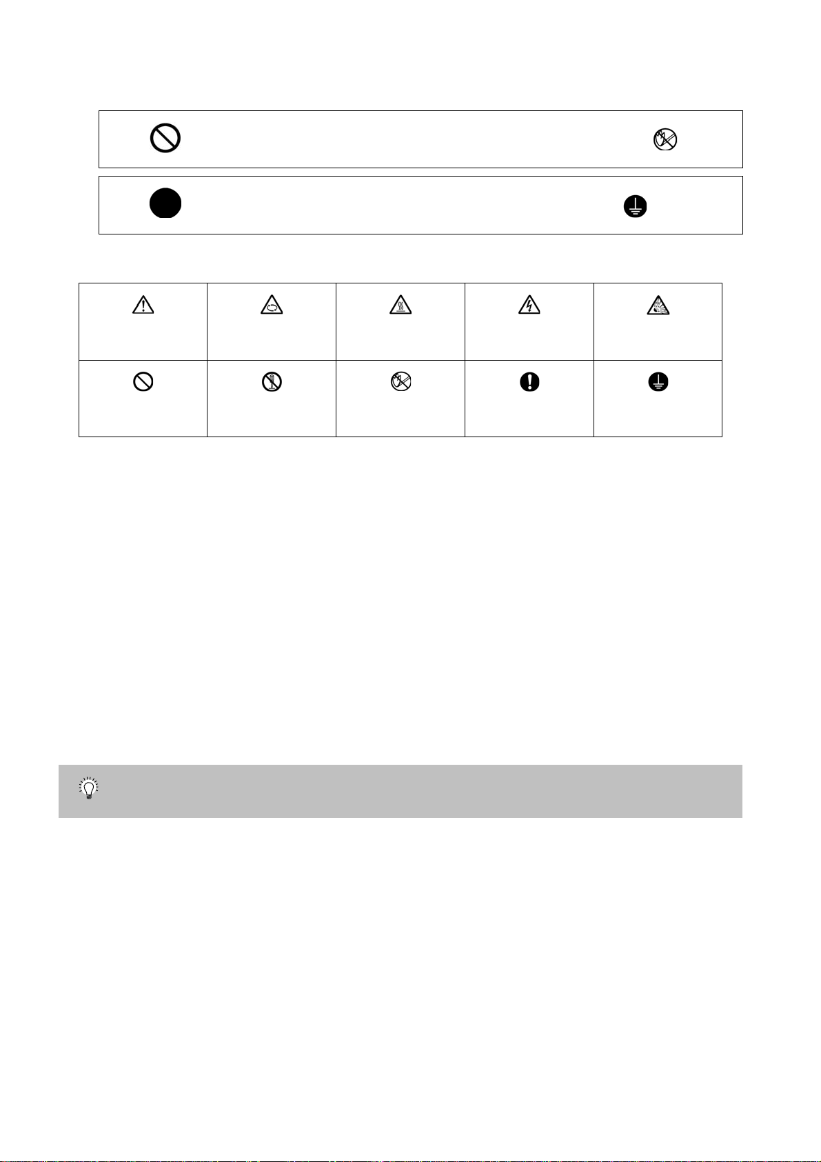
The signs indicating prohibited and mandatory matters are explained below.
Indicates a prohibited matter. For example, "Fire Prohibited" is indicated as .
Indicates a mandatory matter. For example, grounding is indicated as .
The meaning of each pictorial sign is as follows.
CAUTION
Prohibited
CAUTION rotated
Disassembly is
prohibited
object
CAUTION HOT Danger Electric shock
KEEP FIRE AWAY General instruction
Danger explosive
risk
Earth ground
After reading this specifications and instructions manual, store it where the user can access it easily for
reference.
The numeric control unit is configured of the control unit, operation boar d, servo drive unit, spi ndle drive
unit, power supply, servomotor and spindle mo to r, et c.
In this section "Precautions for safety", the following items are generically called the "motor".
• Servomotor
• Linear servomotor
• Spindle motor
In this section "Precautions for safety", the following items are generically called the "unit".
• Servo drive unit
• Spindle drive unit
• Power supply unit
• Scale interface unit
• Magnetic pole detection unit
POINT
Important matters that should be understood for operation of this machine are indicated as a POINT
in this manual.
Page 8

1. Electric shock prevention
Do not open the front cover while the power is ON or during operation . Failure to observe this could lead
to electric shocks.
Do not operate the unit with the front cover removed. The high voltage terminals and charged sections
will be exposed, and can cause electric shocks.
Do not remove the front cover and connector even when the power is OFF unless carrying out wiring
work or periodic inspections. The inside of the units is charged, and can cause electric shocks.
Since the high voltage is supplied to the main circuit connector while the power is ON or during
operation, do not touch the main circuit connector with an adjustment screwdriver or the pen tip. Fa ilure
to observe this could lead to electric shocks.
Wait at least 15 minutes after turning the power OFF, confirm that the CHARGE lamp has gone out, and
check the voltage between P and N terminals with a tester, etc., before starting wiring, maintenance or
inspections. Failure to observe this could lead to electric shocks.
Ground the unit and motor following the standards set forth by each country.
Wiring, maintenance and inspection work must be done by a qualified technician.
Wire the servo drive unit and servomotor after installation. Failure to observe this could lead to electric
shocks.
Do not touch the switches with wet hands. Failure to observe this could lead to electric shocks.
Do not damage, apply forcible stress, place heavy items on the cables or get them caught. Failure to
observe this could lead to electric shocks.
After assembling the built-in IPM spindle motor, if the rotor is rotated by hand etc., voltage occurs
between the terminals of lead. Take care not to get electric shocks.
WARNING
Page 9

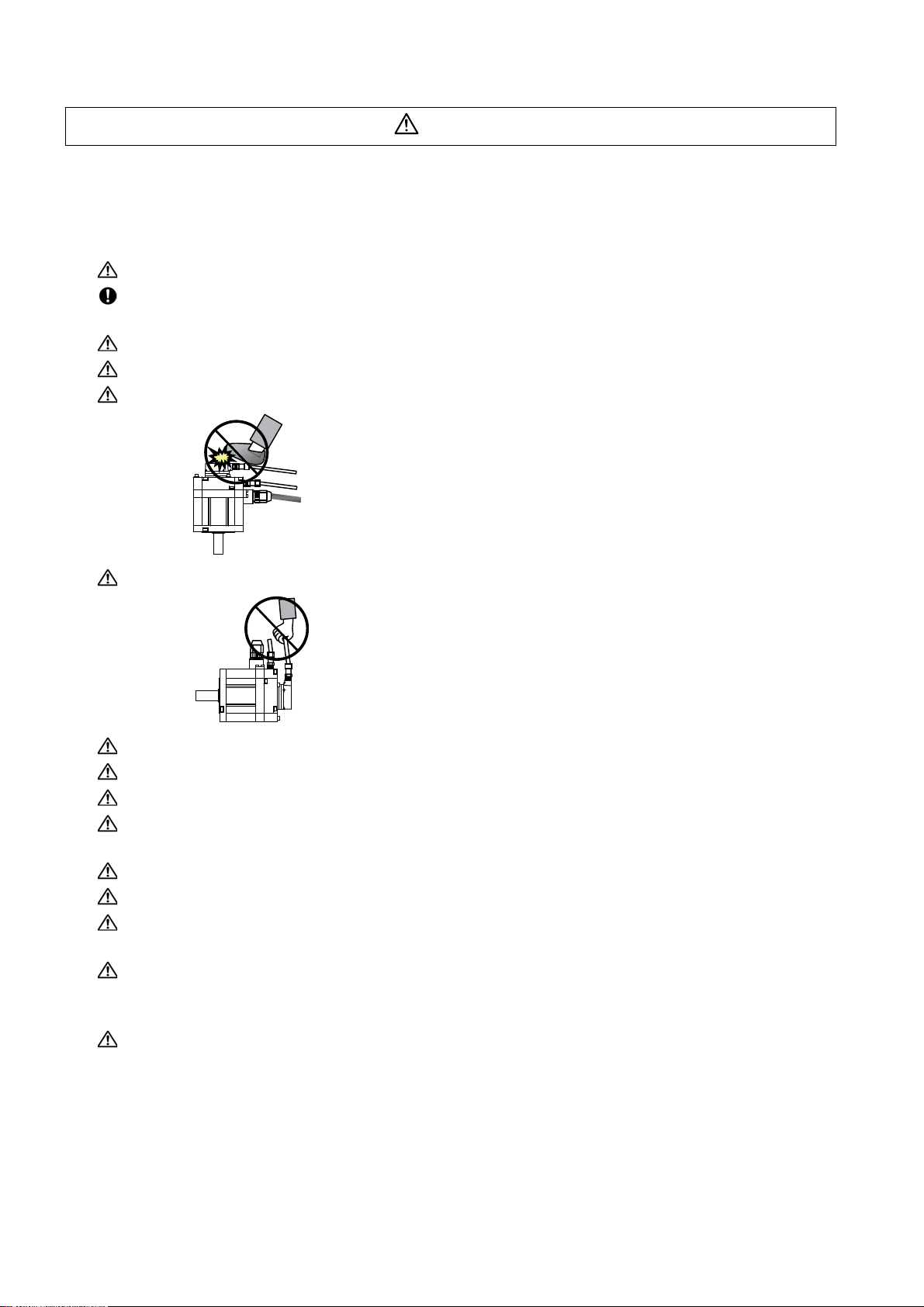
2. Injury prevention
In the system where the optical communication with CNC is executed, do not see directly the light
generated from CN1A/CN1B connector of drive unit or the end of cable. When the light gets into eye,
you may feel something is wrong for eye.
(The light source of optical communication corresponds to class1 defined in JISC6802 or IEC60825-1.)
The linear servomotor, direct-drive motor and built-in IPM spindl e motor uses permanent ma gnets in the
rotor, so observe the following precautions .
(1)Handling
• The linear servomotor, direct-drive motor and built-in IPM spindle motor could adversely affect
medical electronics such as pacemakers, etc., therefore, do not approach the rotor.
• Do not place magnetic materials as iron.
• When a magnetic material as iron is placed, take safety measure not to pinch finger s or hands
due to the magnetic attraction force.
• Remove metal items such as watch, piercing jewelry, necklace, etc.
• Do not place portable items that could malfunction or fail due to the influence of the magnetic
force.
• When the rotor is not securely fixed to the machine or device, do not leave it unattended but store
it in the package properly.
(2)Transportation and storage
• Correctly store the rotor in the package to transport and store.
• During transportation and storage, draw people's attention by applying a notice saying "Strong
magnet-Handle with care" to the package or storage shelf.
• Do not use a damaged package.
(3)Installation
• Take special care not to pinch fingers, etc., when installing (and unpacking) the linear servomotor.
Page 10

1. Fire prevention
CAUTION
Install the units, motors and regenerative resistor on non-combustible material. Direct installation on
combustible material or near combustible materials could lead to fires.
Always install a circuit protector and contactor on the servo drive unit power input as explained in this
manual. Refer to this manual and select the correct circuit protector and contactor. An incorrect
selection could result in fire.
Shut off the power on the unit side if a fault occurs in the units. Fires could be caused if a large current
continues to flow.
When using a regenerative resistor, provide a sequence that shuts off the power with the regenerative
resistor's error signal. The regenerative resistor could abnormally overheat and cause a fire due to a
fault in the regenerative transistor, etc.
The battery unit could heat up, ignite or rupture if submerged in water, or if the poles are incorrectly
wired.
Cut off the main circuit power with the contactor when an alarm or emergency stop occurs.
2. Injury prevention
Do not apply a voltage other than that specified in this manual, on each terminal. Failure to observe this
item could lead to ruptures or damage, etc.
Do not mistake the terminal connections. Failure to observe this item could lead to ruptures or damage,
etc.
Do not mistake the polarity (+,- ). Failure to observe this item could lead to ruptures or damage, etc.
Do not touch the radiation fin on unit back face, regenerative resistor or motor, etc., or place parts
(cables, etc.) while the power is turned ON or immediately after turning the power OFF. These parts
may reach high temperatures, and can caus e bu rn s or part dam a ge .
Structure the cooling fan on the unit back face, etc., etc so that it cannot be touched afte r installation.
Touching the cooling fan during operation could lead to injuries.
Page 11
3. Various precautions
CAUTION
Observe the following precautions. Incorrect handling of the unit could lead to faults, injuries and electric
shocks, etc.
(1) Transportation and installation
Correctly transport the product according to its weight.
Use the motor's hanging bolts only when transporting the motor. Do not transport the machine when the
motor is installed on the machine.
Do not stack the products above the tolerable number.
Follow this manual and install the unit or motor in a place where the weight can be borne.
Do not get on top of or place heavy objects on the unit.
Do not hold the cables, axis or detector when transporting the motor.
Do not hold the connected wires or cables when transporting the units.
Do not hold the front cover when transporting the unit. The unit could drop.
Always observe the installation directions of the units or motors.
Secure the specified distance between the units and control panel, or between the servo drive unit and
other devices.
Do not install or run a unit or motor that is damaged or missing parts.
Do not block the intake or exhaust ports of the motor provided with a cooling fan.
Do not let foreign objects enter the units or motors. In particular, if conductive objects such as screws or
metal chips, etc., or combustible materials such as oil enter, rupture or breakage could occur.
Provide adequate protection using a material such as connector for conduit to prevent screws, metallic
detritus, water and other conductive matter or oil and other combustible matter from entering the motor
through the power line lead-out port.
The units, motors and detectors are precision devices, so do not drop them or apply strong impacts to
them.
Page 12

CAUTION
Store and use the units under the following environment conditions.
Environment Unit Motor
Operation: 0 to 55°C(with no freezing),
Ambient temperature
Ambient humidity
Atmosphere
Altitude
Vibration/impact According to each unit or motor specification
Storage / Transportation: -15°C to 70°C
(with no freezing)
Operation: 90%RH or less
(with no dew condensation)
Storage / Transportation: 90%RH or less
(with no dew condensation)
Indoors (no direct sunlight)
With no corrosive gas, inflammable gas, oil mist, dust or conductive fine particles
Operation/Storage: 1000 meters or less above sea
level,
Transportation: 13000 meters or less above sea
level
(Note 1) For details, confirm each unit or motor specifications in addition.
(Note 2) -15°C to 55°C for linear servomotor.
Securely fix the servomotor to the machine. Insufficient fixing could lead to the servomotor slipping off
during operation.
Always install the servomotor with reduction gear in the designated direction. Failure to do so could lead
to oil leaks.
Structure the rotary sections of the motor so that it can never be touched during operation. Install a
cover, etc., on the shaft.
When installing a coupling to a servomotor shaft end, do not apply an impact by hammering, etc. The
detector could be damaged.
Do not apply a load exceeding the tolerable load onto the servomotor shaft. The shaft could break.
Store the motor in the package box.
When inserting the shaft into the built-in IPM spindle mo tor, do not heat the rotor highe r than 130°C. The
magnet could be demagnetized, and the specifications characteristics will not be ensured.
Always use a nonmagnetic tool (explosion-proof beryllium copper alloy safety tool: NGK Insulators, etc.)
when installing the linear servomotor.
Always provide a mechanical stopper on the end of the linear servomotor's travel path.
If the unit has been stored for a long time, always check the operation before starting actual operation.
Please contact the Service Center, Service Station, Sales Office or delayer.
Operation: 0 to 40°C(with no freezing),
Storage: -15°C to 70°C (Note2) (with no freezing)
Operation: 80%RH or less
(with no dew condensation),
Storage: 90%RH or less
(with no dew condensation)
Operation: 1000 meters or less above sea level,
Storage: 10000 meters or less above sea level
(2) Wiring
Correctly and securely perform the wiring. Failure to do so could lead to abnormal operation of the
motor.
Do not install a condensing capacitor, surge absorber or radio noise filter on the output sid e of the drive
unit.
Correctly connect the output side of the drive unit (terminals U, V, W). Failure to do so could lead to
abnormal operation of the motor.
When using a power regenerative power supply unit, always install an AC reactor for each power supply
unit.
In the main circuit power supply side of the unit, always install an appropriate circuit protector or
contactor for each unit. Circuit protector or contactor cannot be shared by several units.
Page 13
CAUTION
RA
)
COM
(24VDC)
RA
Servodrive unit
Servodrive unit
Control output
signal
Control output
signal
Always connect the motor to the drive unit's output terminals (U, V, W).
Do not directly connect a commercial power supply to the servomotor. Failure to observe this could
result in a fault.
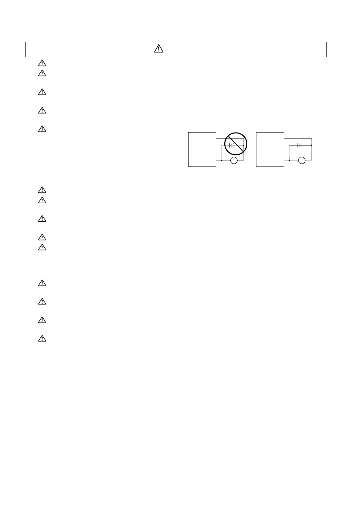
When using an inductive load such as a relay, always connect a diode as a noise measure parallel to
the load.
When using a capacitance load such as a lamp, always connect a protective resistor as a noise
measure serial to the load.
Do not reverse the direction of a diode which
connect to a DC relay for the control output
signals such as contractor and motor brake
output, etc. to suppress a surge. Connecting it
backwards could cause the drive unit to
malfunction so that signals are not output, and
emergency stop and other safety circuits are inoperable.
Do not connect/disconnect the cables connected between the units while the power is ON.
Securely tighten the cable connector fixing screw or fixing mechanism. An insecure fixing could cause
the cable to fall off while the power is ON.
When using a shielded cable instructed in the instruction manual, always ground the cable with a cable
clamp, etc.
Always separate the signals wires from the drive wire and power line.
Use wires and cables that have a wire diameter, heat resistance and flexibility that conforms to the
system.
COM
(24VDC
(3) Trial operation and adjustment
Check and adjust each program and parameter before starting op er ation . Failur e to do so cou l d lead to
unforeseen operation of the machine.
Do not make remarkable adjustments and changes of parameter as the operation could become
unstable.
The usable motor and unit combination is predetermined. Always check the models before starting trial
operation.
The linear servomotor does not have a stopping device such as magnetic brakes. Install a stopping
device on the machine side.
Page 14

(4) Usage methods
CAUTION
In abnormal state, install an external emergency stop circuit so that the operation can be stopped and
power shut off immediately.
Turn the power OFF immediately if smoke, ab nor ma l noise or odors are generated from the unit or
motor.
Do not disassemble or repair this product.
Never make modifications.
When an alarm occurs, the machine will start suddenly if an alarm reset (RST) is carried out while an
operation start signal (ST) is being input. Always confirm that the operation signal is OFF before
carrying out an alarm reset. Failure to do so could lead to accidents or injuries.
Reduce magnetic damage by installing a noise filter. The electronic devices used near the unit could be
affected by magnetic noise. Install a line noise filter, etc., if there is a risk of magnetic noise.
Use the unit, motor and regenerative resistor with the designated combinatio n. Failur e to do so could
lead to fires or trouble.
The brake (magnetic brake) of the servomotor are for ho ldin g, and m ust not b e used fo r nor mal br aking .
There may be cases when holding is not possible due to the magnetic brake's life, the machine
construction (when ball screw and servomotor are coupled via a timing belt, etc.) or the magnetic
brake's failure. Install a stop device to ensure safety on the machine side.
After changing the programs/parameters or after maintenance an d inspection, always test the operation
before starting actual operation.
Do not enter the movable range of the machine during automatic operation. Never place body parts
near or touch the spindle during rotation.
Follow the power supply specification conditions given in each specification for the power (input voltage,
input frequency, tolerable sudden power failure time, etc.).
Set all bits to "0" if they are indicated as not used or empty in the explanation on the bits.
Do not use the dynamic brakes except during the emergency stop. Continued use of the dynamic
brakes could result in brake damage.
If a circuit protector for the main circuit power supply is shared by several units, the circuit protector may
not activate when a short-circuit fault occurs in a small capacity unit. This is dangerous, so never share
the circuit protector.
Page 15
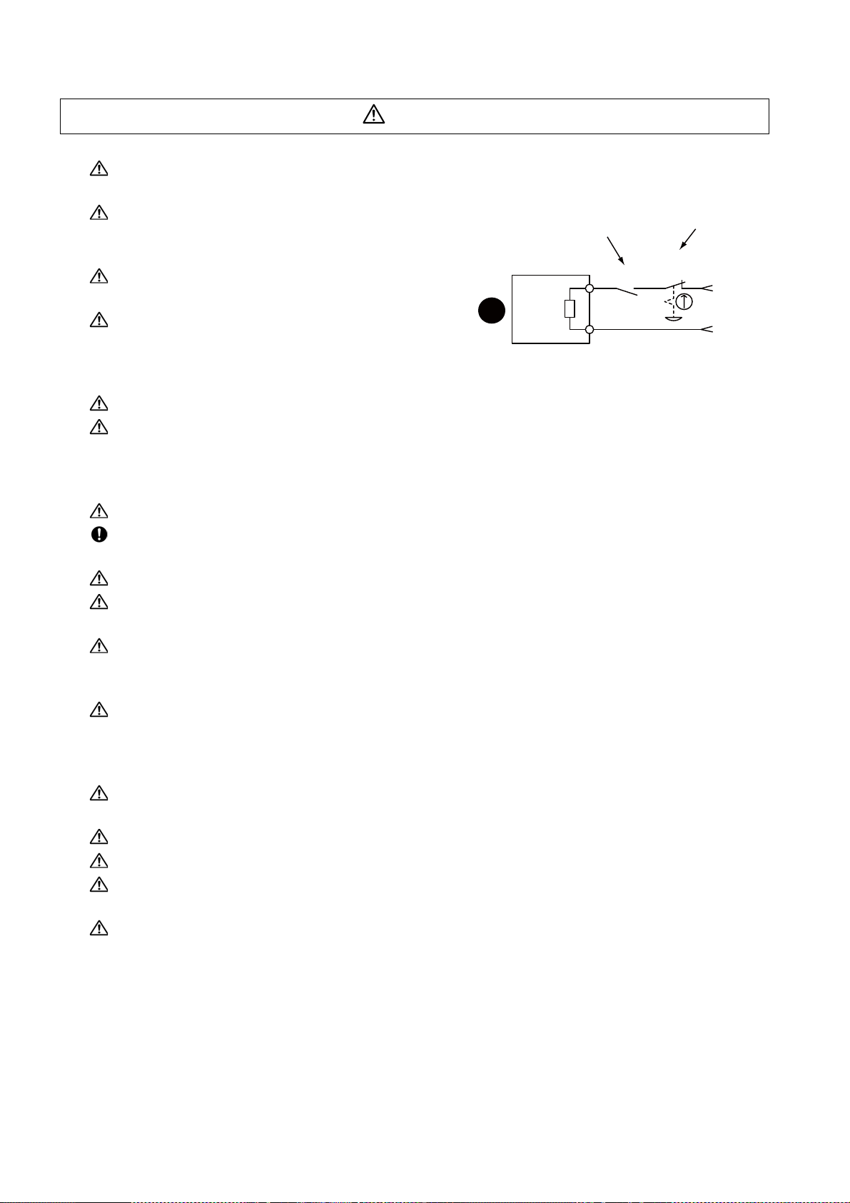
CAUTION
MBR
EMG
Servomotor
Magnetic
brake
Shut off with the servomotor
brake control output.
Shut off with NC brake
control PLC output.
24VDC
(5) Troubleshooting
If a hazardous situation is predicted during power failure or product trouble, use a servomotor with
magnetic brakes or install an external brake mechanism.
Use a double circuit configuration that allows the
operation circuit for the magnetic brakes to be operated
even by the external emergency stop signal.
Always turn the main circuit power of the motor OFF
when an alarm occurs.
If an alarm occurs, remove the cause, and secure the
safety before resetting the alarm.
(6) Maintenance, inspection and part replacement
Always backup the programs and parameters be fo re star tin g ma in te na nc e or insp ect ion s.
The capacity of the electrolytic capacitor will drop over time due to self-discharging, etc. To prevent
secondary disasters due to failures, replacing this part every five years when used under a normal
environment is recommended. Contact the Service Center, Service Station, Sales Office or delayer for
repairs or part replacement.
Do not perform a megger test (insulation resistance measurement) during inspections.
If the battery low warning is issued, back up the machining programs, tool data and parameters with an
input/output unit, and then rep l ac e th e ba ttery.
Do not short circuit, charge, overheat, incinerate or disassemble the battery.
For after-purchase servicing of the built-in motor (including the detector), supplies of servicing parts and
repairs can only be offered.
For maintenance, part replacement, and services in case of failures in the built-in motor (including the
detector), take necessary actions at your end. For spindle drive unit, Mitsubishi can offer the afterpurchase servicing as with the general spindle drive unit.
When a failure has occurred in the built-in motor (including the detector), some period of time can be
required to supply the servicing parts or repair. Prepare the spare parts a t your end whenever possible.
(7) Disposal
Take the batteries and backlights for LCD, etc., off from the controller, drive unit an d motor, and dispose
of them as general industrial wastes.
Do not disassemble the unit or motor.
Dispose of the battery according to local laws.
Always return the secondary side (magnet side) of the linear servomotor to the Service Center or
Service Station.
When incinerating optical communication cable, hydrogen fluoride gas or hydrogen chloride gas which
is corrosive and harmful may be generated. For disposal of optical communication cable, request for
specialized industrial waste disposal services that has incineration facility for disposing hydrogen
fluoride gas or hydrogen chloride gas.
Page 16

CAUTION
(8) Transportation
The unit and motor are precision parts and must be handled carefully.
According to a United Nations Advisory, the battery unit and battery must be transported according to
the rules set forth by the International Civil Aviation Organization (ICAO), International Air
Transportation Association (IATA), International Maritime Organization (IMO), and United States
Department of Transportation (DOT), etc.
(9) General precautions
The drawings given in this manual show the covers and safety partitions, etc., removed to provide a
clearer explanation. Always return the covers or partitions to their respective places before starting
operation, and always follow the instructions given in this manual.
Page 17

Page 18

Treatment of waste
The following two laws will apply when disposing of this product. Considerations must be made to each law.
The following laws are in effect in Japan. Thus, when using this product overseas, the local laws will have a
priority. If necessary, indicate or notify these laws to the final user of the product.
(1) Requirements for "Law for Promotion of Effective Utilization of Resources"
(a) Recycle as much of this product as possible when finished with use.
(b) When recycling, often parts are sorted into steel scraps and electric parts, etc., and sold to scrap
contractors. Mitsubishi recommends sorting the product and selling the members to appropriate
contractors.
(2) Requirements for "Law for Treatment of Waste and Cleaning"
(a) Mitsubishi recommends recycling and selling the product when no longer nee ded according to item
(1) above. The user should make an effort to reduce waste in this manner.
(b) When disposing a product that cannot be resold, it shall be treated as a waste product.
(c) The treatment of industrial waste must be commissioned to a licensed industrial waste treatment
contractor, and appropriate measures, including a manifest control, must be taken.
(d) Batteries correspond to "primary batteries", and must be disposed of according to local disposal
laws.
Page 19

Page 20

Disposal
(Note) This symbol mark is for EU countries only.
This symbol mark is according to the directive 2006/66/EC Article 20 Information for endusers and Annex II.
Your MITSUBISHI ELECTRIC product is designed and manufactured with high quality materials and
components which can be recycled and/or reused.
This symbol means that batteries and accumulators, at their end-of-life, should be disposed of
separately from your household waste.
If a chemical symbol is printed beneath the symbol shown above, this chemical symbol means that the
battery or accumulator contains a heavy metal at a certain concentration. This will be indicated as
follows:
Hg: mercury (0,0005%), Cd: cadmium (0,002%), Pb: lead (0,004%)
In the European Union there are separate collection systems for used batteries and accumulators.
Please, dispose of batteries and accumulators correctly at your local community waste collection/
recycling centre.
Please, help us to conserve the environment we live in!
Page 21

Page 22

本製品の取扱いについて
( 日本語 /Japanese)
本製品は工業用 ( クラス A) 電磁環境適合機器です。販売者あるいは使用者はこの点に注意し、住商業環境以外で
の使用をお願いいたします。
Handling of our product
(English)
This is a class A product. In a domestic environment this product may cause radio interference in which case the
user may be required to take adequate measures.
본 제품의 취급에 대해서
( 한국어 /Korean)
이 기기는 업무용 (A 급 ) 전자파적합기기로서 판매자 또는 사용자는 이 점을 주의하시기 바라며 가정외의 지역에
서 사용하는 것을 목적으로 합니다 .
Page 23

Page 24

Contents
1 Installation..................................................................1 - 1
1-1 Installation of servomotor..................................................................................................................1 - 2
1-1-1 Environmental conditions ................................................ ... ....... ... ... ... ... .... ... ... ... .... ... ... ... . ........1 - 2
1-1-2 Quakeproof level ...................................... ... .......................................... .... ............................... 1 - 3
1-1-3 Cautions for mounting load (prevention of impact on shaft)..................................................... 1 - 4
1-1-4 Installation direction..... ... .... ... ... .......................................... ... .... ............................................... 1 - 4
1-1-5 Shaft characteristics.............................................................. .... ... ... ... ......................................1 - 5
1-1-6 Machine accuracy..................................................................................................................... 1 - 6
1-1-7 Coupling with the load..............................................................................................................1 - 7
1-1-8 Oil/water standards................................... .......................................... ... ................................... 1 - 9
1-1-9 Installation of servomotor ....................................................................................................... 1 - 11
1-1-10 Cable stress.......................................................................................................................... 1 - 12
1-2 Installation of spindle motor............................................................................................................1 - 13
1-2-1 Environmental conditions ... ...... ... .... ... ... ... ... .... ... ... ... .... ... ... ... .... ...... ... ... .... ... ... ... .... ... ... ... . ......1 - 13
1-2-2 Shaft characteristics........................ ... ... ... ... .... ... ... .......................................... ... ....................1 - 14
1-3 Installation of tool spindle motor ....... .......................................... ... ................................................. 1 - 15
1-3-1 Environmental conditions ... ...... ... .... ... ... ... ... .... ... ... ... .... ... ... ... .... ...... ... ... .... ... ... ... .... ... ... ... . ......1 - 15
1-3-2 Shaft characteristics........................ ... ... ... ... .... ... ... .......................................... ... ....................1 - 15
1-4 Installation of the drive unit.............................................................................................................1 - 16
1-4-1 Environmental conditions ... ...... ... .... ... ... ... ... .... ... ... ... .... ... ... ... .... ...... ... ... .... ... ... ... .... ... ... ... . ......1 - 16
1-4-2 Installation direction and clearance........................................................................................1 - 17
1-4-3 Prevention of entering of foreign matter.................................................................................1 - 18
1-4-4 Heating value................................... .......................................... ... .......................................... 1 - 19
1-4-5 Heat radiation countermeasures ........................................... .... ... ... ... ... ....... ... ... .... ... ... ... ... ....1 - 20
1-5 Installation of the spindle detector.................................................................................................. 1 - 22
1-5-1 Spindle side ABZ pulse output detector (OSE-1024 Series)..................................................1 - 22
1-5-2 Spindle side PLG serial output detector (TS5690, MU1606 Series) ......................................1 - 23
1-5-3 Installation accuracy diagnosis for PLG detector ................................................................... 1 - 25
1-6 Noise measures..............................................................................................................................1 - 28
2 Wiring and Connection..............................................2 - 1
2-1 Part system connection diagram ................ ... ... .......................................... ... ................................... 2 - 3
2-2 Main circuit terminal block/control circuit connector .........................................................................2 - 4
2-2-1 Names and applications of main circuit terminal block signals and control circuit connectors.2 - 4
2-2-2 Connector pin assignment .. ... ... .......................................... ... .......................................... ......... 2 - 5
2-2-3 Main circuit connector (CNP1,CNP2,CNP3) wiring method...................................................2 - 11
2-3 NC and drive unit connection.......................................................................................................... 2 - 18
2-4 Connecting with optical communication repeater unit ....................................................................2 - 19
2-5 Motor and detector connection .......................................................................................................2 - 21
2-5-1 Connection of the servomotor ................................................................................................2 - 21
2-5-2 Connection of the full-closed loop system.............................................................................. 2 - 24
2-5-3 Connection of the spindle motor.............................................................................................2 - 26
2-5-4 Connection of the tool spindle motor......................................................................................2 - 28
2-6 Connection of power supply ........................................................................................................... 2 - 31
2-6-1 Power supply input connection........... ... ................................................................................. 2 - 31
2-6-2 Connection of the grounding cable.........................................................................................2 - 32
2-7 Connection of regenerative resistor ............................................................................................... 2 - 33
2-7-1 Standard built-in regenerative resistor (Only for MDS-D-SVJ3)............................................. 2 - 33
2-7-2 External option regenerative resistor......................................................................................2 - 33
2-8 Wiring of the peripheral control....................................................................................................... 2 - 35
2-8-1 Wiring of the Input/output circuit...................... ... ... ... .... ...... ... .... ... ... ... ... .... ... ... ... .... ... ... ... .......2 - 35
2-8-2 Wiring of the contactor control............... ... ... .... ... ... ... .... ... ... ... ....... ... ... ... .... ... ... ... .... ... ... ... .......2 - 37
Page 25

2-8-3 Wiring of the motor magnetic brake (MDS-D-SVJ3)...............................................................2 - 38
2-8-4 Wiring of an external emergency stop.................................................................................... 2 - 40
2-8-5 Safety observation function....................................................................................................2 - 43
2-8-6 Specifications of proximity switch...........................................................................................2 - 47
3 Setup........................................................................... 3 - 1
3-1 Initial setup........................................................................................................................................3 - 2
3-1-1 Setting the rotary switch ...........................................................................................................3 - 2
3-1-2 Setting DIP switch ....................................................................................................................3 - 3
3-1-3 Transition of LED display after power is turned ON .................................................... ... ... ... ... . 3 - 3
3-2 Setting the initial parameters for the servo drive unit............................. ... ... ....................................3 - 4
3-2-1 Setting of servo specification parameters.................................................................................3 - 5
3-2-2 Setting of machine side detector ..............................................................................................3 - 7
3-2-3 List of standard parameters for each servomotor...................................................................3 - 10
3-2-4 Servo parameters ..................................................................................................................3 - 16
3-3 Setting the initial parameters for the spindle drive unit ...................................................................3 - 52
3-3-1 Setting of parameters related to the spindle...........................................................................3 - 52
3-3-2 List of standard parameters for each spindle motor ...............................................................3 - 59
3-3-3 Spindle specification parameters............................................................................................3 - 80
3-3-4 Spindle parameters ................................................................................................................3 - 98
4 Servo Adjustment ......................................................4 - 1
4-1 D/A output specifications for servo drive unit....................................................................................4 - 2
4-1-1 D/A output specifications..........................................................................................................4 - 2
4-1-2 Output data settings ................................................................................................................. 4 - 3
4-1-3 Setting the output magnification...............................................................................................4 - 5
4-2 Servo adjustment procedure.............................................................................................................4 - 6
4-3 Gain adjustment................................................................................................................................4 - 7
4-3-1 Current loop gain......................................................................................................................4 - 7
4-3-2 Speed loop gain........................................................................................................................4 - 8
4-3-3 Position loop gain...................................................................................................................4 - 12
4-4 Characteristics improvement ..........................................................................................................4 - 16
4-4-1 Optimal adjustment of cycle time............................................................................................4 - 16
4-4-2 Vibration suppression measures............................................................................................4 - 19
4-4-3 Improving the cutting surface precision..................................................................................4 - 24
4-4-4 Improvement of characteristics during acceleration/deceleration...........................................4 - 27
4-4-5 Improvement of protrusion at quadrant changeover...............................................................4 - 30
4-4-6 Improvement of overshooting.................................................................................................4 - 35
4-4-7 Improvement of the interpolation control path ........................................................................4 - 38
4-5 Adjustment during full closed loop control ......................................................................................4 - 40
4-5-1 Outline ....................................................................................................................................4 - 40
4-5-2 Speed loop delay compensation ............................................................................................4 - 41
4-5-3 Dual feedback control.............................................................................................................4 - 42
4-6 Settings for emergency stop........................................................................................................... 4 - 44
4-6-1 Deceleration control................................................................................................................4 - 44
4-6-2 Vertical axis drop prevention control ......................................................................................4 - 47
4-6-3 Vertical axis pull-up control.....................................................................................................4 - 50
4-7 Protective functions.........................................................................................................................4 - 52
4-7-1 Overload detection .................................................................................................................4 - 52
4-7-2 Excessive error detection .......................................................................................................4 - 53
4-7-3 Collision detection function.....................................................................................................4 - 54
4-8 Servo control signal ........................................................................................................................4 - 58
4-8-1 Servo control input (NC to Servo)...........................................................................................4 - 58
4-8-2 Servo control output (Servo to NC) ........................................................................................4 - 61
Page 26

5 Spindle Adjustment ...................................................5 - 1
5-1 D/A output specifications for spindle drive unit.................................................................................5 - 2
5-1-1 D/A output specifications.......... ... .... .......................................... ... ... ......................................... 5 - 2
5-1-2 Setting the output data ............................................................................................................. 5 - 3
5-1-3 Setting the output magnification...............................................................................................5 - 6
5-2 Adjustment procedures for each control...........................................................................................5 - 7
5-2-1 Basic adjustments .................................... ... .......................................... .... ...............................5 - 7
5-2-2 Gain adjustment ....................................... ... .... .......................................... ... ............................5 - 8
5-2-3 Adjusting the acceleration/deceleration operation . ... ..............................................................5 - 12
5-2-4 Orientation adjustment ................................ .... ... ... ... .......................................... .... ... .............5 - 19
5-2-5 Synchronous tapping adjustment...........................................................................................5 - 23
5-2-6 Spindle C axis adjustment (For lathe system)........................................................................ 5 - 27
5-2-7 Spindle synchronization adjustment (For lathe system).........................................................5 - 32
5-2-8 Deceleration coil changeover valid function by emergency stop............................................5 - 34
5-2-9 High-response acceleration/deceleration function..................... ... ... ... ... .... ... ... ... .... ... ... ... ... .... 5 - 35
5-2-10 Spindle cutting withstand level improvement................................. ...... .... ... ... ... .... ... ... ... ... .... 5 - 36
5-3 Settings for emergency stop........................................................................................................... 5 - 37
5-3-1 Deceleration control.................................. ... .......................................... .... ... ..........................5 - 37
5-4 Spindle control signal......................................................................................................................5 - 38
5-4-1 Spindle control input (NC to Spindle) .....................................................................................5 - 38
5-4-2 Spindle control output (Spindle to NC)...................................................................................5 - 43
6 Troubleshooting.........................................................6 - 1
6-1 Points of caution and confirmation.................................................................................................... 6 - 2
6-1-1 LED display when alarm or warning occurs .............................................................................6 - 3
6-2 Protective functions list of units ........................................................................................................6 - 4
6-2-1 List of alarms............................... .... ... ... ... .......................................... ... .... ............................... 6 - 4
6-2-2 List of warnings...................................... .......................................... ... ...................................... 6 - 8
6-3 Troubleshooting................................................................................................................................ 6 - 9
6-3-1 Troubleshooting at power ON................................................................................................... 6 - 9
6-3-2 Troubleshooting for each alarm No........................................................................................6 - 10
6-3-3 Troubleshooting for each warning No........................................ ... ... ... .................................... 6 - 35
6-3-4 Parameter numbers during initial parameter error.................................................................. 6 - 38
6-3-5 Troubleshooting the spindle system when there is no alarm or warning................................ 6 - 39
7 Maintenance ...............................................................7 - 1
7-1 Periodic inspections..........................................................................................................................7 - 2
7-1-1 Inspections .. ... ... .... ... ... ... .... .......................................... ... ......................................................... 7 - 2
7-1-2 Cleaning of spindle motor.........................................................................................................7 - 2
7-2 Service parts..................................................................................................................................... 7 - 7
7-3 Adding and replacing units and parts ............................................................................................... 7 - 8
7-3-1 Replacing the drive unit............................................................................................................ 7 - 9
7-3-2 Replacing the unit fan.............................................................................................................7 - 10
7-3-3 Replacing the battery.............................................................................................................. 7 - 14
Appendix 1 Cable and Connector Specifications
...................................................Appendix 1 - 1
Appendix 1-1 Selection of cable ............................................................................................. Appendix 1 - 2
Appendix 1-1-1 Cable wire and assembly ......................................................................... Appendix 1 - 2
Appendix 1-2 Cable connection diagram................................................................................ Appendix 1 - 4
Appendix 1-2-1 Battery cable............................................................................................. Appendix 1 - 4
Appendix 1-2-2 Optical communication repeater unit cable .............................................. Appendix 1 - 5
Page 27

Appendix 1-2-3 Servo / tool spindle detector cable ...........................................................Appendix 1 - 6
Appendix 1-2-4 Spindle detector cable............................................................................Appendix 1 - 10
Appendix 1-3 Connector outline dimension drawings...........................................................Appendix 1 - 12
Appendix 1-3-1 Optical communication cable.................................................................. Appendix 1 - 12
Appendix 1-3-2 DI/O or maintenance connector..............................................................Appendix 1 - 14
Appendix 1-3-3 Servo detector connector .......................................................................Appendix 1 - 15
Appendix 1-3-4 Brake connector .....................................................................................Appendix 1 - 19
Appendix 1-3-5 Power connector.....................................................................................Appendix 1 - 21
Appendix 1-3-6 Drive unit side main circuit connector.....................................................Appendix 1 - 23
Appendix 1-3-7 Spindle detector connector.....................................................................Appendix 1 - 25
Appendix 2 Cable and Connector Assembly
...................................................Appendix 2 - 1
Appendix 2-1 CM10-SPxxS-x(D6) plug connector..................................................................Appendix 2 - 2
Appendix 2-2 CM10-APxxS-x(D6) angle plug connector......................................................Appendix 2 - 10
Appendix 2-3 CM10-SP-CV reinforcing cover for straight plug.............................................Appendix 2 - 20
Appendix 2-4 CM10-AP-D-CV reinforcing cover for angle plug...........................................Appendix 2 - 22
Appendix 2-5 1747464-1 plug connector.............................................................................. Appendix 2 - 24
Appendix 2-5-1 Applicable products................................................................................Appendix 2 - 24
Appendix 2-5-2 Applicable cable .....................................................................................Appendix 2 - 24
Appendix 2-5-3 Related documents.................................................................................Appendix 2 - 24
Appendix 2-5-4 Assembly procedure...............................................................................Appendix 2 - 25
Appendix 3 Precautions in Installing Spindle Motor
...................................................Appendix 3 - 1
Appendix 3-1 Precautions in transporting motor.....................................................................Appendix 3 - 2
Appendix 3-2 Precautions in selecting motor fittings ..............................................................Appendix 3 - 3
Appendix 3-3 Precautions in mounting fittings........................................................................Appendix 3 - 3
Appendix 3-4 Precautions in coupling shafts..........................................................................Appendix 3 - 4
Appendix 3-5 Precautions in installing motor in machine....................... ... .... ... ... ... .................Appendix 3 - 5
Appendix 3-6 Other Precautions.............................................................................................Appendix 3 - 5
Appendix 3-7 Example of unbalance correction......................................................................Appendix 3 - 6
Appendix 3-8 Precautions in balancing of motor with key.......................................................Appendix 3 - 7
Appendix 4 Compliance to EC Directives..Appendix 4 - 1
Appendix 4-1 Compliance to EC Directives............................................................................Appendix 4 - 2
Appendix 4-1-1 European EC Directives ...........................................................................Appendix 4 - 2
Appendix 4-1-2 Cautions for EC Directive compliance......................................................Appendix 4 - 2
Appendix 5 EMC Installation Guidelines ...Appendix 5 - 1
Appendix 5-1 Introduction.......................................................................................................Appendix 5 - 2
Appendix 5-2 EMC instructions...............................................................................................Appendix 5 - 2
Appendix 5-3 EMC measures.................................................................................................Appendix 5 - 3
Appendix 5-4 Measures for panel structure............................................................................Appendix 5 - 3
Appendix 5-4-1 Measures for control panel unit ................................................................Appendix 5 - 3
Appendix 5-4-2 Measures for door ...................................................................................Appendix 5 - 4
Appendix 5-4-3 Measures for operation board panel........................................................ Appendix 5 - 4
Appendix 5-4-4 Shielding of the power supply input section .............................................Appendix 5 - 4
Appendix 5-5 Measures for various cables............................................................................. Appendix 5 - 5
Appendix 5-5-1 Measures for wiring in panel.....................................................................Appendix 5 - 5
Page 28

Appendix 5-5-2 Measures for shield treatment..................................................................Appendix 5 - 5
Appendix 5-5-3 Servo/spindle motor power cable .............................................................Appendix 5 - 6
Appendix 5-5-4 Servo/spindle motor feedback cable .................. ... .... ............................... Appendix 5 - 7
Appendix 5-6 EMC countermeasure parts..............................................................................Appendix 5 - 8
Appendix 5-6-1 Shield clamp fitting ...................................................................................Appendix 5 - 8
Appendix 5-6-2 Ferrite core............................................................................................... Appendix 5 - 9
Appendix 5-6-3 Power line filter....................................................................................... Appendix 5 - 10
Appendix 5-6-4 Surge protector............................ .......................................... .... .............Appendix 5 - 16
Appendix 6 EC Declaration of Conformity
...................................................Appendix 6 - 1
Appendix 6-1 Compliance to EC Directives............................................................................Appendix 6 - 2
Appendix 6-1-1 Low voltage equipment............................................................................. Appendix 6 - 2
Appendix 7 Higher Harmonic Suppression Measure
Guidelines ................................Appendix 7 - 1
Appendix 7-1 Higher harmonic suppression measure guidelines........................................... Appendix 7 - 2
Appendix 7-1-1 Calculating the equivalent capacity of the higher harmonic generator..... Appendix 7 - 3
Page 29

Outline for MDS-D-SVJ3/SPJ3 Series
Specifications Manual (IB-1500158-C)
1 Introduction
1-1 Servo/spindle drive system configuration
1-1-1 System configuration
1-2 Explanation of type
1-2-1 Servomotor type
1-2-2 Servo drive unit type
1-2-3 Spindle motor type
1-2-4 Tool spindle motor type
1-2-5 Spindle drive unit type
2 Specifications
2-1 Servomotor
2-1-1 Specifications list
2-1-2 Torque characteristics
2-2 Spindle motor
2-2-1 Specifications
2-2-2 Output characteristics
2-3 Tool spindle motor
2-3-1 Specifications
2-3-2 Output characteristics
2-4 Drive unit
2-4-1 Installation environment conditions
2-4-2 Servo drive unit
2-4-3 Spindle drive unit
2-4-4 Unit outline dimension drawing
2-4-5 Explanation of each part
3 Function Specifications
Function specifications list
3-1 Base functions
3-1-1 Full closed loop control
3-1-2 Position command synchronous control
3-1-3 Speed command synchronous control
3-1-4 Distance-coded reference position control
3-1-5 Spindle's continuous position loop control
3-1-6 Coil changeover control
3-1-7 Gear changeover control
3-1-8 Orientation control
3-1-9 Indexing control
3-1-10 Synchronous tapping control
3-1-11 Spindle synchronous control
3-1-12 Spindle/C axis control
3-1-13 Proximity switch orientation control
3-2 Servo/Spindle control functions
3-2-1 Torque limit function
3-2-2 Variable speed loop gain control
3-2-3 Gain changeover for synchronous tapping
control
3-2-4 Speed loop PID changeover control
3-2-5 Disturbance torque observer
3-2-6 Smooth High Gain control (SHG control)
3-2-7 High-speed synchronous tapping cont rol
(OMR-DD control)
3-2-8 Dual feedback control
3-2-9 HAS control
3-2-10 Control loop gain changeover
3-2-11 Spindle output stabilizing control
3-2-12 High-response spindle acceleration/
deceleration function
3-3 Compensation controls
3-3-1 Jitter compensation
3-3-2 Notch filter
3-3-3 Adaptive tracking-type notch filte r
3-3-4 Overshooting compensation
3-3-5 Machine end compensation control
3-3-6 Lost motion compensation type 2
3-3-7 Lost motion compensation type 3
3-3-8 Lost motion compensation type 4
3-3-9 Spindle motor temperature compensation
function
3-4 Protection function
3-4-1 Deceleration control at emergency stop
3-4-2 Vertical axis drop prevention/pull-up control
3-4-3 Earth fault detection
3-4-4 Collision detection function
3-4-5 Safety observation function
3-5 Sequence functions
3-5-1 Contactor control function
3-5-2 Motor brake control function
3-5-3 External emergency stop function
3-5-4 Specified speed output
3-5-5 Quick READY ON sequence
3-6 Diagnosis function
3-6-1 Monitor output function
3-6-2 Machine resonance frequency display
function
3-6-3 Machine inertia display function
3-6-4 Motor temperature display function
3-6-5 Load monitor output function
3-6-6 Open loop control function
4 Characteristics
4-1 Servomotor
4-1-1 Environmental conditions
4-1-2 Quakeproof level
4-1-3 Shaft characteristics
4-1-4 Machine accuracy
4-1-5 Oil / water standards
4-1-6 Flange of servo motor
4-1-7 Overload protection characteristics
4-1-8 Magnetic brake
4-1-9 Dynamic brake characteristics
4-2 Spindle motor
4-2-1 Environmental conditions
4-2-2 Shaft characteristics
4-3 Tool spindle motor
4-3-1 Environmental conditions
4-3-2 Shaft characteristics
4-3-3 Tool spindle temperature characteristics
4-4 Drive unit
4-4-1 Environmental conditions
4-4-2 Heating value
Page 30

5 Dedicated Options
5-1 Servo options
5-1-1 Battery option
5-1-2 Ball screw side detector (OSA105-ET2)
5-1-3 Machine side detector
5-2 Spindle options
5-2-1 Spindle side ABZ pulse output detector
(OSE-1024 Series)
5-2-2 Spindle side PLG serial output detector
(TS5690, MU1606 Series)
5-2-3 Spindle side accuracy serial output detector
(ERM280, MPCI Series)
5-3 Detector interface unit
5-3-1 Serial output interface unit for ABZ analog
detector MDS-B-HR
5-3-2 Pulse output interface unit for ABZ analog
detector IBV Series
(Other manufacturer's product)
5-3-3 Serial output interface unit for ABZ analog
detector EIB192M
(Other manufacturer's product)
5-3-4 Serial output interface unit for ABZ analog
detector EIB392M
(Other manufacturer's product)
5-3-5 Serial output interface unit for ABZ analog
detector ADB-20J Series
(Other manufacturer's product)
5-4 Drive unit option
5-4-1 Optical communication repeater unit
(FCU7-EX022)
5-4-2 Regenerative option
5-5 Cables and connectors
5-5-1 Cable connection diagram
5-5-2 List of cables and connectors
5-5-3 Optical communication cable specifications
6 Specifications of Peripheral
Devices
6-1 Selection of wire
6-1-1 Example of wires by unit
6-2 Selection of circuit protector and contactor
6-2-1 Selection of circuit protector
6-2-2 Selection of contactor
6-3 Selection of earth leakage breaker
6-4 Branch-circuit protection (for control power
supply)
6-4-1 Circuit protector
6-4-2 Fuse protection
6-5 Noise filter
6-6 Surge absorber
6-7 Relay
7 Selection
7-1 Selection of the servomotor
7-1-1 Outline
7-1-2 Selection of servomotor capacity
7-1-3 Motor shaft conversion load torque
7-1-4 Expressions for load inertia calculation
7-2 Selection of the spindle motor
7-3 Selection of the regenerative resistor
7-3-1 Regeneration methods
7-3-2 Calculation of the regenerative energy
7-3-3 Calculation of the positioning frequency
Appendix 1 Cable and Connector
Specifications
Appendix 1-1 Selection of cable
Appendix 1-1-1 Cable wire and assembly
Appendix 1-2 Cable connection diagram
Appendix 1-2-1 Battery cable
Appendix 1-2-2 Optical communication repeater
unit cable
Appendix 1-2-3 Servo / tool spindle detector cable
Appendix 1-2-4 Spindle detector cable
Appendix 1-3 Connector outline dimension drawings
Appendix 1-3-1 Optical communication cable
Appendix 1-3-2 DI/O or maintenance connector
Appendix 1-3-3 Servo detector connector
Appendix 1-3-4 Brake connector
Appendix 1-3-5 Power connector
Appendix 1-3-6 Drive unit side main circuit
connector
Appendix 1-3-7 Spindle detector connector
Appendix 2 Restrictions for Lithium
Batteries
Appendix 2-1 Restriction for Packing
Appendix 2-1-1 Target Products
Appendix 2-1-2 Handling by User
Appendix 2-1-3 Reference
Appendix 2-2 Products information data sheet (ER
battery)
Appendix 2-3 Issuing Domestic Law of the United
States for Primary Lithium Battery
Transportation
Appendix 2-3-1 Outline of Regulation
Appendix 2-3-2 Target Products
Appendix 2-3-3 Handling by User
Appendix 2-3-4 Reference
Appendix 2-4 Restriction related to EU Battery
Directive
Appendix 2-4-1 Important Notes
Appendix 2-4-2 Information for end-user
Appendix 3 Compliance to EC
Directives
Appendix 3-1 Compliance to EC Directives
Appendix 3-1-1 European EC Directives
Appendix 3-1-2 Cautions for EC Directive
compliance
Page 31

Appendix 4 EMC Installation
Guidelines
Appendix 4-1 Introduction
Appendix 4-2 EMC instructions
Appendix 4-3 EMC measures
Appendix 4-4 Measures for panel structure
Appendix 4-4-1 Measures for control panel unit
Appendix 4-4-2 Measures for door
Appendix 4-4-3 Measures for operation board
panel
Appendix 4-4-4 Shielding of the power supply
input section
Appendix 4-5 Measures for various cables
Appendix 4-5-1 Measures for wiring in panel
Appendix 4-5-2 Measures for shield treatment
Appendix 4-5-3 Servo/spindle motor power cable
Appendix 4-5-4 Servo/spindle motor feedback
cable
Appendix 4-6 EMC countermeasure parts
Appendix 4-6-1 Shield clamp fitting
Appendix 4-6-2 Ferrite core
Appendix 4-6-3 Power line filter
Appendix 4-6-4 Surge protector
Appendix 5 EC Declaration of
Conformity
Appendix 5-1 Compliance to EC Directives
Appendix 5-1-1 Low voltage equipment
Appendix 6 Instruction Manual for
Compliance with UL/
c-UL Standard
Appendix 6-1 Operation surrounding air am b ien t
temperature
Appendix 6-2 Notes for AC servo/spindle system
Appendix 6-2-1 General Precaution
Appendix 6-2-2 Installation
Appendix 6-2-3 Short-circuit ratings (SCCR)
Appendix 6-2-4 Peripheral devices
Appendix 6-2-5 Field Wiring Reference Table for
Input and Output (Power Wiring)
Appendix 6-2-6 Motor Over Load Protection
Appendix 6-2-7 Flange of servo motor
Appendix 6-2-8 Spindle Drive/Motor
Combinations
Appendix 6-2-9 Servo Drive/Motor Combinations
Appendix 6-3 AC Servo/Spindle System Connection
Appendix 6-3-1 MDS-D/DH/DM-Vx/SP Series
Appendix 6-3-2 MDS-D-SVJ3/SPJ3 Series
Appendix 7 Compliance with
Restrictions in China
Appendix 7-1 Compliance with China CCC
certification system
Appendix 7-1-1 Outline of China CCC certification
system
Appendix 7-1-2 First catalogue of products
subject to compulsory product
certification
Appendix 7-1-3 Precautions for shipping products
Appendix 7-1-4 Application for exemption
Appendix 7-1-5 Mitsubishi NC product subject to/
not subject to CCC certification
Appendix 7-2 Response to the China environment
restrictions
Appendix 7-2-1 Outline of the law on the pollution
prevention and control for
electronic information products
Appendix 7-2-2 Response to the drive product for
Mitsubishi NC
Appendix 7-2-3 Indication based on “Pollution
suppression marking request for
electronic information product”
For outline dimension drawings, refer to "DRIVE SYSTEM DATA BOOK" (IB-1500273(ENG)).
Page 32

Page 33

Function specifications list
<Servo specification>
MDS-D-
V1/V2
●● ● ● ●
●●
Variable
frequency: 4
Fixed
frequency: 1
●● ● ● ●
●● ● ● ●
●● --
1
Base
functions
2
Servo
control
function
3
Compensation
control
4
Protection
function
5
Sequence
function
6
Diagnosis
function
Item
1-1 Full closed loop control ●● - ● (Note2) ●
1-2 Position command synchronous control ●● ● ● ●
1-3 Speed command synchronous control ●● ---
1-4 Distance-coded reference position control ●● ---
2-1 Torque limit function (stopper function) ●● ● ● ●
2-2 Variable speed loop gain control ●● ● ● ●
2-3 Gain changeover for synchronous tapping
control
2-4 Speed loop PID changeover control ●● ● ● ●
2-5 Disturbance torque observer ●● ● ● ●
2-6 Smooth High Gain control (SHG control) ●● ● ● ●
2-7 High-speed synchronous tapping control
(OMR-DD control)
2-8 Dual feedback control ●● - ● (Note2) ●
2-9 HAS control ●● ● ● -
3-1 Jitter compensation ●● ● ● ●
3-2 Notch filter
3-3 Adaptive tracking-type notch filter ●● ---
3-4 Overshooting compensation ●● ● ● ●
3-5 Machine end compensation control ●● ● ● ●
3-6 Lost motion compensation type 2 ●● ● ● ●
3-7 Lost motion compensation type 3 ●● ● ● ●
3-8 Lost motion compensation type 4 ●● ---
4-1 Deceleration control at emergency stop ●●● ● ●
4-2 Vertical axis drop prevention/pull-up con-
trol
4-3 Earth fault detection ●●● ● ●
4-4 Collision detection function ●● ● ● ●
4-5 Safety observation function ●●● ● ●
5-1 Contactor control function MDS-D-CV MDS-DH-CV MDS-D-CV ●●
5-2 Motor brake control function (Note 1) ●● ● ● ●
5-3 External emergency stop function MDS-D-CV MDS-DH-CV MDS-D-CV ●●
5-4 Specified speed output ●● ---
5-5 Quick READY ON sequence ●●● ● -
6-1 Monitor output function ●● ● ● ●
6-2 Machine resonance frequency display func-
tion
6-3 Machine inertia display function ●● ● ● ●
6-4 Motor temperature display function
(Only for linear or direct-drive motor)
(Note 1) For the multiaxis drive unit, a control by each axis is not available.
It is required to turn the servo of all axes OFF in the drive unit in order to enable a motor brake output.
(Note 2) For the drive unit MDS-DM-SPV2/3, this function is not available.
MDS-DH-
V1/V2
Variable
frequency: 4
Fixed
frequency: 1
MDS-DM-
MDS-DM-
V3
●
(Only for 1-axis)●(Only for 1-axis)
Variable
frequency: 4
Fixed
frequency: 1
SPV2F/3F
MDS-DM-
SPV2/3
Variable
frequency: 4
Fixed
frequency: 1
MDS-D-
SVJ3
-
Variable
frequency: 4
Fixed
frequency: 1
●
(Only for
direct-drive
motor)
Page 34

<Spindle specifications>
MDS-D-
SP
●●●● -
●●●●●
Variable
frequency: 4
Fixed
frequency: 1
●●●● -
●●●●●
1
Base
functions
2
Spindle
control
functions
3
Compensation
controls
4
Protection
function
5
Sequence
functions
6
Diagnosis
functions
Item
1-5 Spindle's continuous position loop control ●●●●●
1-6 Coil changeover control ●● - ● -
1-7 Gear changeover control ●●●●●
1-8 Orientation control ●●●●●
1-9 Indexing control ●●●●●
1-10 Synchronous tapping control ●●●●●
1-11 Spindle synchronous control ●●●●●
1-12 Spindle/C axis control ●●●●●
1-13 Proximity switch orientation control ●● - ●●
2-1 Torque limit function ●●●●●
2-2 Variable speed loop gain control ●●●●●
2-5 Disturbance torque observer ●● - ●●
2-6 Smooth High Gain control (SHG control) ●●●●●
2-7 High-speed synchronous tapping control
(OMR-DD control)
2-8 Dual feedback control ●●●●●
2-10 Control loop gain changeover ●●●●●
2-11 Spindle output stabilizing control ●●●●●
2-12 High-response spindle acceleration/decel-
eration function
3-1 Jitter compensation ●●●●●
3-2 Notch filter
3-4 Overshooting compensation ●●●●●
3-6 Lost motion compensation type 2 ●●●●●
3-7 Lost motion compensation type 3 ●● ---
3-9 Spindle motor temperat u r e compensation
function
4-1 Deceleration control at emergency stop ●●●●●
4-3 Earth fault detection ●●●●●
4-5 Safety observation function ●●●●●
5-1 Contactor control function MDS-D-CV MDS-DH-CV MDS-D-CV ●●
5-3 External emergency stop function MDS-D-CV MDS-DH-CV MDS-D-CV ●●
5-4 Specified speed output ●●●● -
5-5 Quick READY ON sequence ●●●●-
6-1 Monitor output function ●●●●●
6-2 Machine resonance frequency display func-
tion
6-3 Machine inertia display function ●●●●●
6-4 Motor temperature display function ●●●●●
6-5 Load monitor output function ●●●●● (Note)
6-6 Open loop control function ●●●●●
(Note) The motor output effective value cannot be displayed.
MDS-DH-
SP
Variable
frequency: 4
Fixed
frequency: 1
MDS-D-
SP2
Variable
frequency: 4
Fixed
frequency: 1
MDS-DMSPV2F/3F
MDS-DM-
SPV2/3
Variable
frequency: 4
Fixed
frequency: 1
MDS-D-
SPJ3
Variable
frequency: 4
Fixed
frequency: 1
Page 35

Page 36

付録
1
章
1 - 1
Contents
1
Installation
1-1 Installation of servomotor.............................................................................. 1 - 2
1-1-1 Environmental conditions...................................................................... 1 - 2
1-1-2 Quakeproof level .................................................................................. 1 - 3
1-1-3 Cautions for mounting load (prevention of impact on shaft).................1 - 4
1-1-4 Installation direction.............................................................................. 1 - 4
1-1-5 Shaft characteristics ............................................................................. 1 - 5
1-1-6 Machine accuracy................................................................................. 1 - 6
1-1-7 Coupling with the load .......................................................................... 1 - 7
1-1-8 Oil/water standards............................................................................... 1 - 9
1-1-9 Installation of servomotor.................................................................... 1 - 11
1-1-10 Cable stress...... .......................................... .... .................................. 1 - 12
1-2 Installation of spindle motor............ ... ... .... ......................................... .... .....1 - 13
1-2-1 Environmental conditions.................................................................... 1 - 13
1-2-2 Shaft characteristics ........................................................................... 1 - 14
1-3 Installation of tool spindle motor ........ ... .... ... ... ... ......................................... 1 - 15
1-3-1 Environmental conditions.................................................................... 1 - 15
1-3-2 Shaft characteristics ........................................................................... 1 - 15
1-4 Installation of the drive unit............. ... ... .... ... .......................................... ... .. 1 - 16
1-4-1 Environmental conditions.................................................................... 1 - 16
1-4-2 Installation direction and clearance ........................................... .... ... .. 1 - 17
1-4-3 Prevention of entering of foreign matter ............................................. 1 - 18
1-4-4 Heating value...................................................................................... 1 - 19
1-4-5 Heat radiation countermeasures......................................................... 1 - 20
1-5 Installation of the spindle detector ............ ... ... ... ... ...................................... 1 - 22
1-5-1 Spindle side ABZ pulse output detector (OSE-1024 Series).............. 1 - 22
1-5-2 Spindle side PLG serial output detector (TS5690, MU1606 Series)...1 - 23
1-5-3 Installation accuracy diagnosis for PLG detector................................ 1 - 25
1-6 Noise measures. ... .......................................... ... ......................................... 1 - 28
1 - 1
Page 37

1 Installation
MITSUBISHI CNC
1-1 Installation of servomotor
CAUTION
1. Do not hold the cables, axis or detector when transporting the motor. Failure to observe this could
lead to faults or injuries.
2. Securely fix the motor to the machine. Insufficient fixing could lead to the motor deviating during
operation. Failure to observe this could lead to injuries.
3. When coupling to a servomotor shaft end, do not apply an impact by hammering, etc. The detector
could be damaged.
4. Never touch the rotary sections of the motor during operations. Install a cover, etc., on the shaft.
5. Do not apply a load exceeding the tolerable load onto the servomotor shaft. The shaft could break.
Failure to observe this could lead to injuries.
6. Do not connect or disconnect any of th e connectors while the power is ON.
1-1-1 Environmental conditions
Environment Conditions
Ambient temperature 0°C to +40°C (with no freezing)
Ambient humidity 80% RH or less (with no dew condensation)
Storage temperature -15°C to +70°C (with no freezing)
Storage humidity 90% RH or less (with no dew condensation )
Atmosphere
Altitude
Vibration
No corrosive gas, inflammable gas, oil mist or dust
Operation / storage: 1000m or less above sea level
Transportation: 10000m or less above sea level
Indoors (no direct sunlight)
X:19.6m/s
2
(2G) Y:19.6m/s2(2G)
1 - 2
Page 38

MDS-D-SVJ3/SPJ3 Series Instruction Manual
1-1 Installation of servomotor
1-1-2 Quakeproof level
Speed (r/min)
0
1000
2000
3000
Vibration amplitude
(double-sway width) (
µ
m)
20
30
40
50
60
80
100
200
Motor type
HF75, 105
HF54, 104, 154, 224, 123, 223, 142
HF204, 354, 303, 302
HF-KP13, 23, 43, 73
24.5m/s
24.5m/s
49m/s
The vibration conditions are as shown below.
Axis direction (X) Direction at right angle to axis (Y)
2
(2.5G) or less 24.5m/s2 (2.5G) or less
2
(2.5G) or less 29.4m/s2 (3G) or less
2
(5G) or less 49m/s2 (5G) or less
Acceleration direction
Servomotor
Y
X
Acceleration
1 - 3
Page 39

1 Installation
MITSUBISHI CNC
1-1-3 Cautions for mounting load (prevention of impact on shaft)
CAUTION
p
[1] When using the servomotor with key way, use the screw hole at the end of the shaft to mount the pulley
onto the shaft. To install, first place the double-end stud into the shaft screw holes, contact the coupling
end surface against the washer, and press in as if tightening with a nut. When the shaft does not ha ve a
key way, use a frictional coupling, etc.
[2] When removing the pulley, use a pulley remover, and make sure not to apply an impact on the shaft.
[3] Install a protective cover on the rotary sections such as the pulley installed on the shaft to ensure safety.
[4] The direction of the detector installed on the servomotor cannot be changed.
Servomotor
Never hammer the end of the shaft during assembly.
Pulley
Double-end stud
Nut
Washer
1-1-4 Installation direction
[1] There are no restrictions on the installation direction. Installation in any direction is possible, but as a
standard the motor is installed so that the motor power line and detector cable cannon plugs (lead-in
wires) face downward. Installation in the standard direction is effective against dripping. Measure to
prevent oil and water must be taken when not installing in the standard direction. When the motor is not
installed in the standard direction, refer to section "1-1-8 Oil/water standards" and take the appropriate
measures.
The brake plates may make a sliding sound when a servomotor with magnetic brake is installed with the
shaft facing upward, but this is not a fault.
1 - 4
U
Down
Standard installation direction
Page 40

MDS-D-SVJ3/SPJ3 Series Instruction Manual
1-1 Installation of servomotor
1-1-5 Shaft characteristics
Radial load
Thrust load
L
CAUTION
There is a limit to the load that can be applied on the motor shaft. Make sure that the load applied on the
radial direction and thrust direction, when mounted on the machine, is belo w the tolerable values given
below. These loads may affect the motor output torque, so consider them when designing the machine.
Servomotor Tolerable radial load Tolerable thrust load
HF75T, 105T (Taper shaft) 245N (L=33) 147N
HF75S, 105S (Straight shaft) 245N (L=33) 147N
HF54T, 104T, 154T, 224T,123T, 223T, 142T (Taper shaft) 392N (L=58) 490N
HF54S, 104S, 154S, 224S,123S, 223S, 142S (Straight shaft) 980N (L=55) 490N
HF204S, 354S, 303S, 302S (Straight shaft) 2058N (L=79) 980N
HF-KP13 (Straight shaft) 88N (L=25) 59N
HF-KP23, 43 (Straight shaft) 245N (L=30) 98N
HF-KP73 (Straight shaft) 392N (L=40) 147N
(Note 1) The tolerable radial load and thrust load in the above table are values applied when each motor is
used independently.
(Note 2) The symbol L in the table refers to the value of L below.
L : Length from flange installation surface to center of load weight [mm]
1. Use a flexible coupling when connecting with a ball screw, etc., and keep the shaft core deviation
to below the tolerable radial load of the shaft.
2. When directly installing the gear on the motor shaft, the radial load increases as the diameter of the
gear decreases. This should be carefully considered when designing the machine.
3. When directly installing the pulley on the motor shaft, carefully consider so that the radial load
(double the tension) generated from the timing belt tension is less than the values shown in the
table above.
4. In machines where thrust loads such as a worm gear are applied, carefully consider providing
separate bearings, etc., on the machine side so that loads exceeding the tolerable thrust loads are
not applied to the motor.
1 - 5
Page 41

1 Installation
MITSUBISHI CNC
1-1-6 Machine accuracy
Machine accuracy of the servo motor's output shaft and around the installation part is as below.
(Excluding special products)
Accuracy (mm)
Amplitude of the flange surface to the
output shaft
Amplitude of the flange surface's fitting
outer diameter
Amplitude of the output shaft end c 0.02 0.02 0.03 0.03
Measurement
point
a 0.05 0.06 0.08 0.08
b 0.04 0.04 0.06 0.08
Less than 100 100 SQ., 130 SQ. 176 SQ. - 250 SQ. 280 or over
Flange size [mm]
a c
b
1 - 6
Page 42

MDS-D-SVJ3/SPJ3 Series Instruction Manual
1-1 Installation of servomotor
1-1-7 Coupling with the load
٤
٤٤٤٤٤
٤
٤٤٤٤٤
×
ٌٌٌ
٤
ٌ
٤
×
٤
CAUTION
There are several ways to couple the motor shaft and machi ne, su ch as di rect coupling with flexible coupling
or rigid coupling, gear connection, timing belt connection, etc.
Summarized comparison is as follows.
No
Noise
cation
Direct coupling
with
flexible coupling
Direct coupling
with
rigid coupling
Gear
Timing belt
lubri-
×
Back-
lash
٤
Rigidity
If the cautions in motor installation in the above table are not observed, the motor will have a broken
shaft, or the bearing will have a shorter life. Carry out design and installation adjustment so that the
load on the motor shaft will be below the tolerable loads mentioned in "1-1-5 Shaft characteristics".
(1) Direct coupling - Flexible coupling
When coupling the load directly, a flexible coupling is recommended. The benefits of a flexible coup ling
are as below.
(a) Shaft's angle deviation and core deviation can be absorb ed to some ex tent, so a djustment in motor
installation is easier.
However, in the case of single, shaft core deviation cannot be allowed, so it is required to design
and adjust so that the shaft cores of the motor and ball screw align. Check the specification of the
coupling to use. If the shaft core deviation exceeds the coupling's tolerable level, the motor will
have a broken shaft, or the bearing will have a shorter life. Thus, in order to simplify the installation
adjustment, use a double flexible coupling.
×
Reliability
in coupling
Looseness of bolt
Looseness of bolt
Tooth chipping
Belt is broken
Life
ٌ
×
Torque
increased
at deceler-
ation
×
× ×
٤
٤
Degree of
freedom in
motor installation
ٌ
Cautions in motor
installation
Shaft core deviation
(In the case of single)
Shaft core deviation
Angle deviation
Backlash too small
Pitch diameter too small
Belt stretched too much
Pitch diameter too small
(b) Less looseness produces less vibration and less noise at the coupling part.
On the other hand, if assembling is loose, lower rigidity may be caused. When using a coupling with
lower rigidity, the accuracy in centering the cor e doesn't ha ve to be h igh, however, it is un desirable
for servo. In order to fully utilize the servo's efficiency to ensure the maximum durability of the
equipments, it is required to use a highly rigid coupling, and to fully align the shaft cores in the initial
installation. It is also required to select the optimum flexible coupling according to the working
conditions, and use it correctly according to the manufacturer's specification manual.
Example of direct coupling with load
Load shaft
Spun ring
(a) Taper shaft
Motor shaft
Flexible coupling
Load shaft
Flexible coupling
Motor shaft
Spun ring
(b) Straight shaft
1 - 7
Page 43

1 Installation
MITSUBISHI CNC
(2) Direct coupling - Rigid coupling
Load side
Coupling
Motor side
0.01mm or less
A rigid coupling has benefits such as high rigidity, and relatively lower price. However, shaft core
deviation and angle deviation of the motor shaft and ball screw are not allowed, so full attention is
required in installing the rigid coupling. Shaft core deviation is desired to be 0.01mm or less. If enough
accuracy cannot be ensured, the motor will have a broken shaft, or the bearing will have a shorter life.
In addition, note that a rigid coupling is not acceptable for HF-KP Series servo motors.
Also note that the motor side ball screw bearing must be locked so that to avoid the thrust load on the
motor shaft due to expansion and contraction of the ball screw.
(3) Gear connection
Gear's accuracy and backlash amount
greatly affect on the machine's positioning
accuracy and noise during operation.
Thus, according to the machine's
specification, appropriately select the
accuracy and backlash amount.
In gear connection, it is required to take
measures against oil to enter the motor.
Load side
Example of gear connection with load
Motor side
1 - 8
Page 44

MDS-D-SVJ3/SPJ3 Series Instruction Manual
1-1 Installation of servomotor
1-1-8 Oil/water standards
[1] The motor protective format uses the IP type, which complies with IEC Standard. However, these
Standards are short-term performance specifications. They do not g uarantee contin uous environme ntal
protection characteristics. Measures such as covers, etc., must be taken if there is any possibility that oil
or water will fall on the motor, and the motor will be constantly wet and permeated by water. Note that
the motor’s IP-type is not indicated as corrosion-resistant.
Oil or water
Servomotor
[2] When a gear box is installed on the servomotor, make sure that the oil level height from the center of the
shaft is higher than the values given below. Open a breathing hole on the gear box so that the inner
pressure does not rise.
Servomotor Oil level (mm)
HF75, 105 15
HF54, 104, 154, 224, 123, 223, 142 22.5
HF204, 354, 303, 302 30
HF-KP13 9.5
HF-KP23, 43 12.5
HF-KP73 15
Gear
Oil level
Lip
Servomotor
Oil seal
1 - 9
Page 45

1 Installation
MITSUBISHI CNC
[3] When installing the servomotor horizontally, set the power cable and detector cable to face downward.
CAUTION
<Fault> Capillary tube phenomenon
When installing vertically or on an inclination, provide a cable trap.
Cable trap
1. The servomotors, including those having IP65 specifications, do not have a completely waterproof
(oil-proof) structure. Do not allow oil or water to constantly contact the motor, enter the motor, or
accumulate on the motor. Oil can also enter the motor through cutting chip accumulation, so be
careful of this also.
2. When the motor is installed facing upwards, take measures on the machine side so that gear oil,
etc., does not flow onto the motor shaft.
[4] Do not use the unit with the cable submer ged in oil or wate r.
(Refer to following drawing.)
Cover
Servomotor
Oil water
[5] Make sure that oil and water do not flow along the cable into the motor or detector.
(Refer to right drawing.)
Cover
Servomotor
1 - 10
<Fault> Respiration
Page 46

MDS-D-SVJ3/SPJ3 Series Instruction Manual
1-1 Installation of servomotor
[6] When installing on the top of the shaft end, make sure that oil from the gear box, etc., does not enter the
Lubricating oil
servomotor. The servomotor does not have a waterproof structure.
Gear
Servomotor
1-1-9 Installation of servomotor
Mount the servo motor on a flange which has the following size or produces an equivalent or higher heat
dissipation effect:
Flange size
(mm)
150x150x6 100W
250x250x6 200 to 400W
250x250x12 0.5 to 1.5kW
300x300x20 2.0 to 7.0kW
800x800x35 9.0 to 11.0kW
Servo Motor
HF, HF-KP
1 - 11
Page 47

1 Installation
MITSUBISHI CNC
1-1-10 Cable stress
4 7 10 20 40 70 100 200
1× 10
8
5× 10
7
2× 10
7
1× 10
7
5× 10
6
2× 10
6
1× 10
6
5× 10
5
2× 10
5
1× 10
5
5× 10
4
3× 10
4
Detector cable bending life
(Material of Mitsubishi optional detector cable: A14B2343)
(Note)
The values in this graph are calculated values and are not guaranteed.
Bending radius (mm)
No. of bends (times)
4 7 10 20 40 70 100 200
3 x 10⁴
5 x 10⁴
1 x 10⁵
2 x 10⁵
5 x 10⁵
1 x 10⁶
2 x 10⁶
5 x 10⁶
1 x 10⁷
2 x 10⁷
5 x 10⁷
1 x 10⁸
[1] Sufficiently consider the cable clamping method so that bending stress and the stress from the cable's
own weight is not applied on the cable connection part.
[2] In applications where the servomotor moves, make sure that excessive stress is not applied on the
cable.
If the detector cable and servomotor wiring are stor ed in a cab le bear and th e servomotor m oves, make
sure that the cable bending part is within the range of the optional detector cable.
Fix the detector cable and power cable enclosed with the servomotor.
[3] Make sure that the cable sheathes will not be cut by sharp cutting chips, worn or stepped on by workers
or vehicles.
The bending life of the detector cable is as shown below. Regard this with a slight allowance. If the
servomotor/spindle motor is installed on a machine that moves, make the bending radius as large as
possible.
1 - 12
Page 48

MDS-D-SVJ3/SPJ3 Series Instruction Manual
1-2 Installation of spindle motor
1-2 Installation of spindle motor
CAUTION
1. Do not hold the cables, axis or detector when transporting the motor. Failure to observe this could
lead to faults or injuries.
2. Securely fix the motor to the machine. Insufficient fixing could lead to the motor deviating during
operation. Failure to observe this could lead to injuries.
3. When coupling to a servomotor shaft end, do not apply an impact by hammering, etc. The detector
could be damaged.
4. Never touch the rotary sections of the motor during operations. Install a cover, etc., on the shaft.
5. Do not apply a load exceeding the tolerable load onto the servomotor shaft. The shaft could break.
Failure to observe this could lead to injuries.
6. Do not connect or disconnect any of the connectors while the power is ON.
1-2-1 Environmental conditions
Environment Conditions
Ambient temperature 0°C to +40°C (with no freezing)
Ambient humidity 90%RH or less (with no dew condensation)
Storage temperature -20°C to +65°C (with no freezing)
Storage humidity 90%RH or less (with no dew condensation)
Atmosphere
Altitude
(Note) Refer to each spindle motor specifications for details on the spindle motor vibration conditions.
No corrosive gases, flammable gases, oil mist or dust
Indoors (Where unit is not subject to direct sunlight)
Operation/storage: 1000m or less above sea level
Transportation: 10000m or less above sea level
1 - 13
Page 49

1 Installation
MITSUBISHI CNC
1-2-2 Shaft characteristics
Radial load
(Note) The load point is at the one-half of the shaft length.
CAUTION
There is a limit to the load that can be applied on the motor shaft. Make sure that the load applied on the
radial direction, when mounted on the machine, is be low the to ler able valu es give n below. Th ese load s also
affect the motor output torque, so consider them when designing the machine.
Spindle motor Tolerable radial load
SJ-VL2.2-02ZT 196N
SJ-VL11-10FZT 245N
SJ-VL0.75-01T, SJ-VL1.5-01T 490N
SJ-D3.7/100-01, SJ-DJ5.5/100-01
SJ-V2.2-01T, SJ-V3.7-01T, SJ-V5.5-01ZT, SJ-V7.5-01ZT, SJ-V7.5-03ZT,
SJ-VL11-05FZT-S01, SJ-VL11-07ZT
SJ-D5.5/100-01, SJ-DJ7.5/100-01 1470N
SJ-D7.5/100-01, SJ-D11/80-01, SJ-DJ11/100-01
SJ-V11-01ZT
980N
1960N
Consider on the machine side so that the thrust loads are not applied to the spindle motor.
1 - 14
Page 50

MDS-D-SVJ3/SPJ3 Series Instruction Manual
1-3 Installation of tool spindle motor
1-3 Installation of tool spindle motor
1-3-1 Environmental conditions
Environment Conditions
Ambient temperature 0°C to +40°C (with no freezing)
Ambient humidity 80% RH or less (with no dew condensation)
Storage temperature -15°C to +70°C (with no freezing)
Storage humidity 90% RH or less (with no dew condensation)
Atmosphere
Altitude
No corrosive gas, inflammable gas, oil mist or dust
Operation / storage: 1000m or less above sea level
Transportation: 10000m or less above sea level
Vibration
1-3-2 Shaft characteristics
There is a limit to the load that can be applied on the motor shaft. Make sure that the load applied on the
radial direction and thrust direction, when mounted on the machine, is belo w the tolerable values given
below. These loads may affect the motor output torque, so consider them when designing the machine.
Tool spindle motor Tolerable radial load Tolerable thrust load
HF-KP46, 56 245N (L=30) 98N
HF-KP96 392N (L=40) 147N
HF75S, 105S 245N (L=33) 147N
HF54S, 104S, 154S, 224S, 123S, 223S 980N (L=55) 490N
HF204S, 303S 2058N (L=79) 980N
(Note 1) The tolerable radial load and thrust load in the above table are values applied when each motor is
used independently.
(Note 2) The symbol L in the table refers to the value of L below.
Indoors (no direct sunlight)
X:19.6m/s
2
(2G) Y:19.6m/s2(2G)
L
Radial load
Thrust load
L: Length from flange installation surface to center of load mass [mm]
1 - 15
Page 51

1 Installation
MITSUBISHI CNC
1-4 Installation of the drive unit
CAUTION
1. Install the unit on noncombustible material. Direct installation on combustible material or near
combustible materials may lead to fires.
2. Follow the instructions in this manual and install the unit while allowing for the unit mass.
3. Do not get on top of the units or motor, or place heavy objects on the unit.
Failure to observe this could lead to injuries.
4. Always use the unit within the designated environment conditions.
5. Do not let conductive objects such as screws or metal chips, etc., or combustible materials such as
oil enter the units.
6. Do not block the units intake and outtak e po rts. Doing so could lead to failure.
7. The units and servomotor are precision devices, so do not drop them or apply strong impacts to
them.
8. Do not install or run units or servomotor that is damaged or missing parts.
9. When storing for a long time, please contact your dealer.
10. Always observe the installation directions. Failure to observe this could lead to faults.
11. Secure the specified distance between the units and panel, or between the units and other
devices. Failure to observe this could lead to faults.
1-4-1 Environmental conditions
Environment Conditions
Ambient temperature 0°C to +55°C (with no freezing)
Ambient humidity 90%RH or less (with no dew condensation)
Storage temperature -15°C to +70°C (with no freezing)
Storage humidity 90%RH or less (with no dew condensation)
Atmosphere
Altitude
Vibration
no corrosive gases, inflammable gases, oil mist, dust or conductive particles
Operation/storage: 1,000m or less above sea level
Transportation: 13,000m or less above sea level
Operation/storage: 4.9m/s
(Note) When installing the machine at 1,000m or more above sea level, the heat dissipation
characteristics will drop as the altitude increases.
The upper limit of the ambient temperature drops 1°C with every 100m increase in altitude.
(The ambient temperature at an altitude of 2,000m is between 0 and +45°C.)
Indoors (no direct sunlight);
2
(0.5G) or less Transportation: 49m/s2 (5G) or less
1 - 16
Page 52

MDS-D-SVJ3/SPJ3 Series Instruction Manual
1-4 Installation of the drive unit
1-4-2 Installation direction and clearance
100mm
10mm 10mm
80mm
100mm
Controlbox
Top
Bottom
Wiringallowance
ormore
Controlbox
ormore
ormore
ormore
ormore
CAUTION
Wire each unit in consideration of the maintainability and the heat dissipation, as well as secure sufficient
space for ventilation.
Installation clearance
- For the heat radiation, secure the following dimensions around the unit.
- Secure the distance shown below for clearance between the unit side face and the device which is a
noise source of power wire or relay, etc.,.
- Secure clearance for installing the unit so that the connector can be inserted or pull out.
(1) Installation of one drive unit
(2) Installation of two or more drive units
Leave a large clearance between the top of the drive unit and the inter nal surface of the control box, and
install a fan to prevent the internal temperatur e of th e con tr ol box fro m exce e din g th e en vir onm en ta l
conditions.
10mm
or more
1. The ambient temperature condition for the drive units is 55°C or less.
2. Because heat can easily accumulate in the upper portion of the units, give sufficient consideration
to heat dissipation when designing the panel. If required, install a fan in the panel to agitate the
heat in the upper portion of the units.
Control box
100mm
or more
100mm
10mm
or more
or more
10mm
or more
1 - 17
Page 53

1 Installation
MITSUBISHI CNC
1-4-3 Prevention of entering of foreign matter
Treat the cabinet with the following items.
(1) Make sure that the cable inlet is dust and oil proof by using packing, etc.
(2) Make sure that the external air does not enter inside by using head radiating holes, etc.
(3) Close all clearances of the cabinet.
(4) Securely install door packing.
(5) If there is a rear cover, always apply packing.
(6) Oil will tend to accumulate on the top. Take special measures such as oil-proofing to the top so that oil
does not enter the cabinet from the screw holds.
(7) After installing each unit, avoid machining in the periphery. If cutting chips, etc., stick onto the electronic
parts, trouble may occur.
(8) When using the unit in an area with toxic gases or high levels of dust, protect the unit with air purging
(system to blow clean air so that the panel's inner pressure is higher than the outer pressure).
1 - 18
Page 54

MDS-D-SVJ3/SPJ3 Series Instruction Manual
1-4 Installation of the drive unit
1-4-4 Heating value
POINT
50%
100%
Unit Load rate
Servo drive unit
Spindle drive unit
Each heating value is calculated with the following values.
The values for the servo drive unit apply at 50% of the stall output. The values for the spind le drive unit apply
for the continuous rated output.
Servo drive unit Spindle drive unit
Type
MDS-D-SVJ3-
03NA 25 075NA 50
04NA 35 22NA 90
07NA 50 37NA 130
10NA 90 55NA 150
20NA 130 75NA 200
35NA 195 110NA 300
Heating value
[W]
Inside panel Inside panel
Type
MDS-D-SVJ3-
Heating value
[W]
1. Design the panel's heating value taking the actual axis operation (load rate) into consideration.
2. The following table shows a load rate in a general machine tool.
1 - 19
Page 55

1 Installation
MITSUBISHI CNC
1-4-5 Heat radiation countermeasures
(1) Heat radiation countermeasures in the control panel
In order to secure reliability and life, design the temperature in the panel so that the ambient
temperature of each unit is 55°C or less.
If the heat accumulates at the top of the unit, etc., install a fan or heat exchanger so that the
temperature in the panel remains constant.
Please refer to following method for heat radiation countermeasures.
Calculate total heat radiation of each
Calculate panel’s cooling capacity
unit in panel (W)
(W1)
Comparison of
W and W1
W҇W1
Manufacturing and evaluation
Evaluate temperature
in panel
T 10
Completion
W>W1
Consider heat
exchanger
Consider adding fan or
heat exchanger
T > 10
<Hypothetical conditions >
[1] Average temperature in panel: T
[2] Panel peripheral temperature: Ta
[3] Internal temperature rise value:
<Point>
[1] Refer to the section “1-3-4 Heating value” for the heat
generated by each unit.
[2] Refer to the following calculation for calculation W1 of the
panel’s cooling capacity (thin steel plate).
W1 = U x A x
U: 6W/m
4W/m
A: Effective heat radiation area [m
T: Internal temperature rise value (10°C)
[3] Points in manufacturing and evaluation
Understanding the temperature rise in the panel, and
install a fan or heat exchanger.
T (average value) 10°C
T
(maximum value) 15°C
max
T
2
x °C (with internal agitating fan)
2
x °C (without internal agitating fan)
㧔
Heat dissipation area in panel㧕
Sections contacting other objects are excluded.
55°C
0 to 45°C
T=T-Ta
2
max
]
=10°C
Examples of mounting heat exchanger and temperature measurement positions (reference)
1 - 20
Flow of air
Relay, etc
Heat
exchanger
Unit
Temperature measurement positions
Heat
exchanger
Relay, etc
Unit
Flow of air
Page 56

MDS-D-SVJ3/SPJ3 Series Instruction Manual
1-4 Installation of the drive unit
The following shows a calculation example for considering heat radiation countermeasures.
A=0.6×0.3+0.6×0.6×2+0.6×0.3×2=1.26(m)
2
(Top face) (Front/back face)
(Side face)
≦
POINT
<Control panel outline dimension (assumption) >
When installing four units which have the heating value in the panel of 15W
Top of panel inside Fan for agitating
600
600
300
Heat radiation area (A): When a bottom section contacts with a machine
(Note) Actually, sections contacting other ob jec ts ar e excluded.
Heating value in panel (W): when installing four units which are 15W
W = 15 x 4 = 60 (W)
<Considering necessity of agitating fan>
1 Temperature standard
(1) Standard of temperature in panel (around each unit) T 55°C
(2) External peripheral temperature Ta = 0 to 45°C
(3) Internal temperature rise value DT = T - Ta (MAX) = 10°C
2 Cooling capacity of control panel (W1)
W1 = U x A x DT DT = Internal temperature rise value (=10°C)
2
U = 6W/m
4W/m
A = Effective heat radiation area (m
・ °C (with internal agitating fan)
2
・ °C (without internal agitating fan)
2
)
(1) With internal agitating fan W1 = 6 x 1.26 x 10 = 75.6 (W) > 60 (W)
(2) Without internal agitating fan W1 = 4 x 1.26 x 10 = 50.4 (W) < 60 (W) -- Internal fan is required.
Measure an actual internal temperature, and install a fan or heat exchanger which agitates the heat at
the top of the unit if the temperature rise exceeds 10°C.
1 - 21
Page 57

1 Installation
MITSUBISHI CNC
1-5 Installation of the spindle detector
Opposite detector shaft
side
Flexible coupling
CAUTION
1-5-1 Spindle side ABZ pulse output detector (OSE-1024 Series)
To maintain the detector life and performance, a flexible coupling should be used to couple the spindle side
detector and C-axis detector with the spindle.
Detector
0.02
0.02
Detector and coupling installation accuracy
Recommended coupling
Recommendation 1 Recommend ation 2
Manufacturer Tokushu Seiko Eagle
Model Model M1 FCS38A
Resonance frequency 1374Hz 3515Hz
Position detection error
Tolerable speed 20,000r/min 10,000r/min
Mis-alignment
Outline dimensions
Confirm that the gear ratio (pulley ratio) of the sp indle end to the detector is 1:1.
Refer to the coupling catalog, etc., for details on the coupling.
Core deviation 0.7mm 0.16mm
Angle displacement 1.5° 1.5°
Max. length 74.5mm 33mm
Max. diameter φ57mm φ38mm
0.8×10
-3
° 1.2×10⁻³ °
1 - 22
Page 58

MDS-D-SVJ3/SPJ3 Series Instruction Manual
1-5 Installation of the spindle detector
1-5-2 Spindle side PLG serial output detector (TS5690, MU1606 Series)
Detection
gears
Sensor section
Output connector
※Thermal sensor
terminals
※Thermal sensor terminals are not used
when the detector is installed on the spindle side.
(1) Part configuration
The detector is configured of a sensor and detection gear. The sensor an d detection gear must be used
in the designated combination.
These are precision parts, and require care when handling. Do not apply an excessive force on the
sensor's detection surface, as this could result in faults. Do not pull and apply a load on the lead wires.
Make sure that foreign matters (iron chips, etc.) do not get on the sensor's detection surface or detection
gears. If any foreign matter should get on these parts, carefully remove while taking ca re not to damage
the parts. When handling the detection gears, take care not to damage or deform the teeth.
Spindle side PLG serial output detector TS5690 Series
(2) Installing the detection gears
[1] Install the detection gears so that the first gear's teeth side (Z phase) face the sensor's lead side.
[2] The detection gears and shaft or sleeve should be fixed with shrink fitting. Refer to the following
table for the shrink fitting values. The detection gears should be heated evenly between 120 and
150°C using an electric furnace, etc.
Guideline for detection gear shrink fitting values
Inner diameter
(mm)
φ40 0.020 to 0.040 φ140 0.050 to 0.085
φ70 0.030 to 0.055 φ160 0.060 to 0.090
φ80 0.030 to 0.055 φ215 0.080 to 0.110
φ125 0.050 to 0.085
Shrink fitting (mm)
[3] Keep the deflection of the outer diameter, when the detection gears are installed on the shaft, to
0.02mm or less.
[4] To remove a detection gear fixed with shrink fitting, use the screw holes opened in the axial
direction for pulling (two M5 screw holes or two M8 screw holes), or push the end with a jig. Carry
Inner diameter
(mm)
Shrink fitting (mm)
out this work carefully. Applying excessive force when pulling out the gears could cause the inner
diameter of the detection gears to deform.
[5] Before reusing detection gears which have been removed, always measure the inner diameter
dimensions, and carefully check that the inner diameter is not deformed, and that the sufficient
tightening amount can be secured. Do not reuse the detection gears if the inner diameter is
deformed, or if any abnormality such as damage to the teeth is found.
1 - 23
Page 59

1 Installation
MITSUBISHI CNC
(3) Installing the sensor section
16.5mm
22.5mm ± 0.25mm
Sensor installation surface
Sensor installation seat
Installing the detector
R section
Z
phase
side
Deflection of the outer
diameter
0.02mm or less
To the end of the outer diameter
[1] Prepare the notched fitting section at the machine side's
installation position to be of the specified dimensions in
advance.
[2] With the sensor installation seat's R section butted against
the notched fitting section, fix the sensor installation seat with
a mounting screw (M5 x 0.8 screws). A locking agent should
be applied on the mounting screw before it is tightened.
[3] Fix the sensor with its R section butted against the notched
fitting section so that the position relation between the
detection gear and sensor is kept constant. This ensures
favorable accuracy of the sensor installation.
[4] Keep the deviation of the sensor center and outer diameter
center of the detection gear to ±0.25mm or less. If the center
deviation cannot be directly measured, set so that the
dimension from the sensor installing surface to the outer
diameter edge of the detection gears is 22.5±0.25mm. (Some
detection gears have thickness at the inner diameter section.)
[5] Make sure that force is not constantly applied on the sensor's lead wires.
To install the sensor section, the notched fitting section on the machine side must have the specified
POINT
dimensions.
The sensor's installation accuracy is assured by adjusting the outside dimensions of the notched
fitting section.
Lead wire
3.0mm
Butt the back side of the sensor installation seat
against here
Butt the R section of the sensor installation seat
against here
Notched section's
outer diameter
screw holes' height
from the rotation center
2-M5×0.8 screw
38mm
Shape of notched fitting section
Installing dimension of the sensor sec t io n
Sensor series type
Screw holes’ height from the
rotation center (mm)
TS5690N6400 51.4 φ72.0
TS5690N1200 77.0 φ122.0
TS5690N2500 128.2 φ223.6
Notched fitting section's outer
Notched section's
outer diameter
diameter (mm)
+0.060
-0.010
+0.025
-0.025
+0.025
-0.025
1 - 24
Page 60

MDS-D-SVJ3/SPJ3 Series Instruction Manual
1-5 Installation of the spindle detector
1-5-3 Installation accuracy diagnosis for PLG detector
CAUTION
Spindle
motor
Spindle
MU1606 (Gear)
TS5690 (Sensor)
Spindle
gear
Motor gear
(6) Judging the installation
gap using the D/A output
signal waveform.
MU1606 (Gear)
TS5690 (Sensor)
Open loop
(2) Open loop setting
(3) Power ON again
(4) Spindle rotation at the
100r/min command
(1) Power ON
(1) Power ON
(5) Spindle rotation
(1) Outline
PLG detects the speed and position by the rotation of the ge ar installed at the motor end or spindle end.
Adjustment-free PLG can be used without adjusting the waveform after installing the sensor section
(TS5690 Series) on the machined notched fitting section. With this function, whether the PLG
installation position is OK or not can be judged using the D/A output of the spindle drive unit while
rotating the spindle in an open loop. For an IPM spindle motor, the waveform should be measured while
rotating the spindle by hand because an open loop operation cannot be carried out.
Make sure that the motor can be rotated freely in the unloaded state without being locked.
To CN2
To CN3
Example: For full closed mode
1 - 25
Page 61

1 Installation
MITSUBISHI CNC
(2) Setting the parameters
The parameters related to the installation accuracy diagnosis for PLG detector are shown below.
【#13018(PR)】 SP018 SPEC2 Spindle specification 2
bit 1 : oplp Open loop
0: Disable 1: Enable
【#13113】 SP113 OPLP Current command value for open loop
Set the current command value for when the open loop control is enabled.
When "0" is set, the state will be the same as when "50" is set.
When not using, set to "0".
The open loop control is enabled when "SP018 (SPEC2)/bit1 (oplp)" is set to "1".
---Setting range---
0 to 999 (Short-time rated %)
1 - 26
Page 62

MDS-D-SVJ3/SPJ3 Series Instruction Manual
1-5 Installation of the spindle detector
(3) Details for PLG installation diagnosis
CAUTION
Installation error judgment of the adjustment-free PLG can be checked using the D/A output of the
spindle drive unit. The setting numbers of D/A output are shown below. For the output waveform, 2.5V
represents a normal state and +1V or -1V of the normal state represents an abnormal state.
*Set the D/A output numbers to the spindle parameters "#13125(SP125)" and "#13126(SP126)".
Because the D/A output of the drive unit is 2ch, perform the check for both at the motor e nd and spindle
end in full closed mode.
D/A output
No.
120
121
122
123
5.0V
2.5V
0.0V
Details Description
Motor end PLG installation
Gap diagnosis
Motor end PLG installation
All errors diagnosis
Spindle end PLG installation
Gap diagnosis
Spindle end PLG installation
All errors diagnosis
The gap is excessive
+1V
The gap is too small
The result of the quality judgement for the gap of the motor end PLG is
output.
When the gap is good, =2.5V is output. When the gap is excessive,
=2.5+1V is output and when the gap is too small, =2.5-1V is output.
The result of the quality judgement for the installed position of the motor
end PLG is output.
When the sensor installation is good, =2.5V is output. When sensor installation is incorrect (such as a center deviation between a sensor and gear,
and Z-phase error), =2.5+1V is output.
The result of the quality judgement for the gap of the spindle end PLG is
output.
The output procedure is the same as that of motor end PLG.
The result of the quality judgement for the installed position of the spindle
end PLG is output.
The output procedure is the same as that of motor end PLG.
The gap is good when the
waveform is constantly at
2.5V during the rotation.
-1V
5.0V
2.5 V
0.0V
Offset fault
Gap fault
Z-phase error
+1V
The installation is good when
the waveform is constantly at
2.5V during the rotation.
Waveform example
when the gap is not good
when all results of the diagnosis are not good
When the D/A output parameter "#13125(SP125)" is set to 120(=D/A output of ch1), and
"#13126(SP126)" is set to 121(=D/A output of ch2), the check is performed at the motor end detector.
POINT
When the D/A output of ch1 is 2.5V and ch2 is 3.5V(=2.5+1V), for example, the gap is normal,
however, the center deviation (offset) between a sensor and gear occurs, so check again after the
sensor installed position is finely adjusted. Adjust until the two D/A outputs finally become 2.5V during
spindle rotation.
When the sensor installed position is finely adjusted, adjust after the power of the drive unit is turned
OFF.
(4) Related alarms
There is no alarm related to the installation accuracy diagnosis for PLG detector.
Waveform example
1 - 27
Page 63

1 Installation
MITSUBISHI CNC
1-6 Noise measures
Noise includes "propagation noise" gen erated from the relay, etc., and p ropagated along a cable causing the
drive unit to malfunction, and "radiated noise" propagated through air from a periph eral device, etc., and
causing the power supply unit or drive unit to malfunction.
Always implement these noise measures to prevent the peripheral devices an d unit from malfunctioning. The
measures differ according to the noise propagation path, so refer to the following explanation and take
appropriate measures.
(1) General noise measures
(a) Avoid laying the drive unit's power line and signal wire in a parallel or bundled state. Always
separate these wires. Use a twisted pair shielded wire for the detector cable and sign al wires such
as the communication cable connected with the NC unit, and accurately ground the devices.
(b) Use one-point grounding for the drive unit and motor.
(c) Accurately ground the AC reactor.
(2) Propagation noise measures
Take the following measures when noise generating devices are installed and the drive unit could
malfunction.
(a) Install a surge killer on devices (magnetic contacts, relays, etc.) which generate high levels of
noise.
(b) Install a power line filter in the stage before the drive unit.
(c) Install a ferrite core on the signal wire.
(d) Ground the shield of the servo detector's cable with a cable clamp.
(e) Wire the spindle PLG detector cable away from other wires.
(3) Measures against radiated noise
The types of propagation paths of the noise and the noise measures for each propagation path are
shown below.
Noise generated from
drive unit
Airborne
propagation noise
Magnetic induction
noise
Static induction
noise
Cable propagation
noise
Path [4]
and [5]
Noise directly radiated
from drive unit
Noise radiated from
power line
Noise radiated from
servomotor/spindle motor
Noise propagated over
power line
Noise lead in from
grounding wire by
leakage current
Path [1]
Path [2]
Path [3] Path [6]
Path [7]
Path [8]
1 - 28
Page 64

MDS-D-SVJ3/SPJ3 Series Instruction Manual
1-6 Noise measures
[5]
[7]
[2]
[1]
[3]
Servomotor
Spindle motor
[2]
Drive
unit
[6]
[4]
M
Instrument
[7]
Receiver
Generated noise of drive system
Noise propagation path Measures
When devices such as instrument, receiver or sensor, which handle minute signals and
are easily affected by noise, or the signal wire of these devices, are stored in the same
panel as the drive units and the wiring is close, the device could malfunction due to airborne propagation of the noise. In this case, take the following measures.
(a) Install devices easily affected as far away from the drive units as possible.
[1] [2] [3]
[4] [5] [6]
[7]
[8]
(b) Lay devices easily affected as far away from the signal wire of the drive unit as possible.
(c) Avoid laying the signal wire and power line in a parallel or bundled state.
(d) Insert a line noise filter on the input/output wire or a radio filter on the input to suppress the noise radiated from the wires.
(e) Use a shield wire for the signal wire and power line, or place in separate metal ducts.
If the signal wire is laid in parallel to the power line, or if it is bundled with the power line,
the noise could be propagated to the signal wire and cause malfunction because of the
magnetic induction noise or static induction noise. In this case, take the following measures.
(a) Install devices easily affected as far away from the drive unit as possible.
(b) Lay devices easily affected as far away from the signal wire of the drive unit as possible.
(c) Avoid laying the signal wire and power line in a parallel or bundled state.
(d) Use a shield wire for the signal wire and power line, or place in separate metal ducts.
If the power supply for the peripheral devices is connected to the drive unit in the same
system as the drive units, the noise generated from the power supply unit could back flow
over the power line and cause the devices to malfunction. In this case, take the following
measures.
(a) Install a radio filter on the drive unit's power line.
(b) Install a power filter on the drive unit's power line.
If a closed loop is created by the peripheral device and drive unit's grounding wire, a leakage current could flow and cause the device to malfunction.
In this case, change the device grounding methods and the grounding place.
Sensor
power
supply
[8]
Sensor
1 - 29
Page 65

1 - 30
Page 66

付録
2
章
2 - 1
Contents
2
Wiring and Connection
2-1 Part system connection diagram................................................................... 2 - 3
2-2 Main circuit terminal block/control circuit connector...................................... 2 - 4
2-2-1 Names and applications of main circuit terminal block signals
and control circuit connectors...............................................................2 - 4
2-2-2 Connector pin assignment.................................................................... 2 - 5
2-2-3 Main circuit connector (CNP1,CNP2,CNP3) wiring method ............... 2 - 11
2-3 NC and drive unit connection....................................... ... ....... ... ... ... ... .... ... .. 2 - 18
2-4 Connecting with optical communication repeater unit................................. 2 - 19
2-5 Motor and detector connection ...................................................................2 - 21
2-5-1 Connection of the servomotor............................................................. 2 - 21
2-5-2 Connection of the full-closed loop system.......................................... 2 - 24
2-5-3 Connection of the spindle motor......................................................... 2 - 26
2-5-4 Connection of the tool spindle motor.................................................. 2 - 28
2-6 Connection of power supply............ ... ... .... ... ... ... ......................................... 2 - 31
2-6-1 Power supply input connection............................................... ... .... .....2 - 31
2-6-2 Connection of the grounding cable..................................................... 2 - 32
2-7 Connection of regenerative resistor .. ... .... ... ... ...... .... ... ... ... .... ... ... ... ... .... ... .. 2 - 33
2-7-1 Standard built-in regenerative resistor (Only for MDS-D-SVJ3) .........2 - 33
2-7-2 External option regenerative resistor... ... ... ... ...................................... 2 - 33
2-8 Wiring of the peripheral control................................................................... 2 - 35
2-8-1 Wiring of the Input/output circuit......................................................... 2 - 35
2-8-2 Wiring of the contactor control............................................................2 - 37
2-8-3 Wiring of the motor magnetic brake (MDS-D-SVJ3)........................... 2 - 38
2-8-4 Wiring of an external emergency stop................................................ 2 - 40
2-8-5 Safety observation function ................................................................ 2 - 43
2-8-6 Specifications of proximity switch....................................................... 2 - 47
2 - 1
Page 67

2 Wiring and Connection
MITSUBISHI CNC
1. Wiring work must be done by a qualified technician.
DANGER
CAUTION
Servo drive unit
Servo drive unit
Control output
signal
Control output
signal
RA
COM
(24VDC)
COM
(24VDC)
RA
2. Wait at least 15 minutes after turning the power OFF and check the voltage with a tester, etc.,
before starting wiring. Failure to observe this could lead to electric shocks.
3. Securely ground the drive units and servo/spindle motor.
4. Wire the drive units and servo/spindle motor after installation. Failure to observe this could lead to
electric shocks.
5. Do not damage, apply forcible stress, place heavy items on the cables or get them caught. Failure
to observe this could lead to electric shocks.
6. Always insulate the power terminal connection section. Failure to observe this could lead to electric
shocks.
1. Correctly and securely perform the wiring. Failure to do so could result in runaway of the servo/
spindle motor or injury.
2. Do not mistake the terminal connections.
3. Do not mistake the polarity ( + , - ). Failure to observe this item could lead to ruptures or damage,
etc.
4. Do not mistake the direction of the diodes for the surge absorption installed on the DC relay for the
motor brake and contactor (magnetic contactor) control. The signal might not be output when a
failure occurs.
5. Electronic devices used near the drive units may receive magnetic obstruction. Reduce the effect
of magnetic obstacles by installing a noise filter, etc.
6. Do not install a phase advancing capacitor, surge absorber or radio noise filter on the powe r li ne
(U, V, W) of the servo/spindle motor.
7. Do not modify this unit.
8. If the connectors are connected incorrectly, faults could occur. Make sure that the connecting
position and the connection are correct.
9. When grounding the motor, connect to the protective grounding terminal on the drive units, and
ground from the other protective grounding terminal.(Use one-point grounding)
Do not separately ground the connected motor and drive unit as noise could be generated.
2 - 2
Page 68

MDS-D-SVJ3/SPJ3 Series Instruction Manual
2-1 Part system connection diagram
2-1 Part system connection diagram
OPT1,2
CN1A
CN9
CN1B
PLG
CN3
CN1A
CN9
CN1B
CNP2
CNP1
CNP2
CNP3
CNP2
CNP1
CNP2
CNP3
D
:Main circuit
:Control circuit
Mitsubishi CNC
Servo drive unit
Ground
Motor side
detector
Spindle drive unit
Ground
Machine side
detector
Optical communication cable
Optical communication
cable
Regenerative
resistor unit
Spindle
motor
Servo
motor
Circuit
protector
Contactor
Spindle side
detector
Contactor
Circuit
protector
Circuit
protector
Circuit
protector
Regenerative
resistor unit
When using a built-in
regenerative resistor,
use a shorted wire.
:Ground
CN3
P
C
R
S
T
R
S
T
L1
L2
L3
L11
L21
CN2
U
V
W
L11
L21
P
C
L1
L2
L3
CN2
U
V
W
(Note 1) The total length of the optical communication cable from the NC must be within 30m and the
(Note 2) The connection method will differ according to the used motor.
minimum-bending radius within 80mm.
(Note 3) Install the dedicated battery for the detector back up outside of the drive unit's bottom surface.
(Note 4) The main circuit ( ◎ ), control circuit ( ○ ) and ground ( ● ) are safely separated.
(Note 5) Connect the ground of the motor to the ground of the connected drive unit.
2 - 3
Page 69

2 Wiring and Connection
MITSUBISHI CNC
2-2 Main circuit terminal block/control circuit connector
CAUTION
2-2-1 Names and applications of main circuit terminal block signals and control circuit
connectors
The following table shows the details for each terminal block signal.
Name Signal name Description
L1 . L2 . L3
(N . P1 . P2) Not used Not used (Short between P1 and P2.)
P.C.D
L11 L21
U . V . W Motor output
Main circuit power
supply
Regenerative
resistor
Control circuit power
supply
Protective grounding
(PE)
1. When sharing a circuit protector for several drive units, of a short-circuit fault occurs in a small
capacity unit, the circuit protector could trip. This can be hazardous, so do not share the circuit
protector.
Main circuit power supply input terminal
Connect a 3-phase 200VAC (50Hz) or 200 to 230VAC (60Hz).
Regenerative resistor connection terminal
When using the built-in regenerative resistor, short between P and D.
P to D is wired at shipment.
When using the external option regenerative resistor, disconnect the wire between P and
D, and wire the external option regenerative resistor between P and C.
Control circuit power supply input terminal
Connect a single-phase 200VAC (50Hz) or 200 to 230VAC (60Hz).
Servo/spindle motor power output terminal (3-phase AC output)
The servo/spindle motor power terminal (U, V, W) is connected.
Grounding terminal
The servomotor/spindle motor grounding terminal is connected and grounded.
2. Be sure to use the circuit protector of proper capacity for each drive unit.
2 - 4
Page 70

MDS-D-SVJ3/SPJ3 Series Instruction Manual
2-2 Main circuit terminal block/control circuit connector
2-2-2 Connector pin assignment
CAUTION
U
V
W
Do not apply a voltage other than that specified in Instruction Manual on each terminal. Failure to
observe this item could lead to rupture or damage, etc.
(1) Main circuit terminal block and connector
Power supply unit
Unit
Terminal
Terminal
position
[1] CNP1
MDS-D-SVJ3-03NA to 04NA
[1]
[2]
[3]
[4]
MDS-D-SVJ3-07NA
MDS-D-SPJ3-075NA
[1]
[2]
[3]
[4]
L1
L2
L3
N
P1
P2
Terminal
[2] CNP2
specification/
Pin
assignment
[3] CNP3
[4]
Screw size: M4 x 10
Tightening torque: 1.2Nm
(Note) The illustrations of drive units are shown as an example.
P
C
D
L11
L21
2 - 5
Page 71

2 Wiring and Connection
MITSUBISHI CNC
Unit
L1
L2
L3
N
P1
P2
P
C
D
L11
L21
Terminal
MDS-D-SVJ3-10NA to 20NA
MDS-D-SPJ3-22NA
MDS-D-SVJ3-35NA
MDS-D-SPJ3-37NA
Terminal
position
Terminal
specification/
Pin
assignment
[1] CNP1
[2] CNP2
[1]
[2]
[3]
[4]
[1]
[3]
[2]
[4]
L1
L2
L3
N
P1
P2
P
C
D
L11
L21
[3] CNP3
[4]
U
V
W
Screw size: M4×10
Tightening torque: 1.2Nm
(Note) The illustrations of drive units are shown as an example.
U
V
W
2 - 6
Page 72

MDS-D-SVJ3/SPJ3 Series Instruction Manual
2-2 Main circuit terminal block/control circuit connector
Unit
[1]
[1]
[2]
[3]
Terminal
Terminal
position
MDS-D-SPJ3-55NA to 75NA MDS-D-SPJ3-110NA
[2]
[3]
[1] TE1
Terminal
specification/
Pin
[2] TE2
assignment
[3]
Screw size: M4 x 10
Tightening torque: 1.2Nm
(Note) The illustrations of drive units are shown as an example.
Screw size: M4 x 10
Tightening torque: 1.2Nm
Screw size: M3.5 x 6
Tightening torque: 0.8Nm
2 - 7
Page 73

2 Wiring and Connection
MITSUBISHI CNC
(2) Control circuit connector
Pin No.
No.1
No.10
No.11
No.20
No.2 No.10
No.1 No.9
No.1
No.2
Unit
Terminal
Connector
position
[1] CN1A
[2] CN1B
MDS-D-SVJ3-03NA to 04NA
[3]
[1]
[2]
[4]
[5]
[6]
Optical communication connector
MDS-D-SVJ3-07NA
MDS-D-SPJ3-075NA
[3]
[1]
[2]
[4]
[5]
[6]
DI/O or Maintenance connector
[3] CN9
Connector
specification
CN2: Motor side detector connector
CN3: Machine side / spindle side detector connector
[4] CN2
[5] CN3
Battery connector
[6] BAT
(Note)
(Note 1) [6] connector is not used for the spindle drive unit.
(Note 2) The illustrations of drive units are shown as an example.
2 - 8
Page 74

MDS-D-SVJ3/SPJ3 Series Instruction Manual
2-2 Main circuit terminal block/control circuit connector
Unit
[1]
[2]
[3]
[4]
[5]
[6]
[1]
[2]
[3]
[4]
[5]
[6]
No.1
No.2
Terminal
Connector
position
[1] CN1A
[2] CN1B
MDS-D-SVJ3-10NA to 20NA
MDS-D-SPJ3-22NA
Optical communication connector
MDS-D-SVJ3-35NA
MDS-D-SPJ3-37NA
DI/O or Maintenance connector
Pin No.
Connector
[3] CN9
No.1
No.10
No.11
No.20
specification
CN2: Motor side detector connector
CN3: Machine side / spindle side detector connector
[4] CN2
No.2 No.10
[5] CN3
No.1 No.9
Battery connector
[6] BAT
(Note)
(Note 1) [6] connector is not used for the spindle drive unit.
(Note 2) The illustrations of drive units are shown as an example.
2 - 9
Page 75

2 Wiring and Connection
MITSUBISHI CNC
Unit
[1]
[2]
[3]
[4]
[5]
Pin No.
No.1
No.10
No.11
No.20
No.2 No.10
No.1 No.9
Terminal
MDS-D-SPJ3-55NA to 75NA MDS-D-SPJ3-110NA
Connector
position
[1] CN1A
[2] CN1B
Optical communication connector
[3]
[1]
[2]
[4]
[5]
DI/O or Maintenance connector
Connector
[3] CN9
specification
CN2: Motor side detector connector
CN3: Machine side / spindle side detector connector
[4] CN2
[5] CN3
(Note) The illustrations of drive units are shown as an example.
2 - 10
Page 76

MDS-D-SVJ3/SPJ3 Series Instruction Manual
2-2 Main circuit terminal block/control circuit connector
2-2-3 Main circuit connector (CNP1,CNP2,CNP3) wiring method
CNP2
CNP1
CNP3
549280610(Molex)
549270510(Molex)
549280310(Molex)
Driveunit
ConnectorforCNP1
ConnectorforCNP2
ConnectorforCNP3
<Applicablecableexample>
CablefinishOD:to Ǿ3.8mm
Use the supplied drive unit power supply connectors for wiring of CNP1, CNP2 and CNP3.
For the wire size used for wring, refer to the section "5-1 selection of wire" in MDS-D-SVJ3/SPJ3
POINT
Series Specifications Manual.
MDS-D-SPJ3-55NA/75NA/110NA does not have these connectors.
(1) MDS-D-SVJ3-03NA/04NA/07NA
(a) Drive unit power supply connectors
(b) Termination of the cables
Solid wire: After the sheath has been stripped, the cable can be used as it is.
Sheath
Core
, MDS-D-SPJ3-075NA
8 to 9mm
Twisted wire: Use the cable after stripping the sheath and not twisting the core. At this time, take
care to avoid a short caused by the loose wires of the core and the adjacent pole.
Do not solder the core as it may cause a contact fault. Alternatively, a bar terminal
may be used to put the wires together.
Cable size Bar terminal type
[mm2]
AWG For 1 cable For 2 cables
1.25 16
1.5 16 AI1.5-8BK
214
BT1.25-9-1 - NH1 NICHIFU
TUB-1.25 - YHT-2210 Japan Solderless Terminal
AI-TWIN2×1.5-8BK
AI-TWIN2×1.5-12BK
BT2-9-1 - NH1 NICHIFU
TUB-2 - YHT-2210 Japan Solderless Terminal
Crimping tool Manufacturer
CRIMPFOX-UD6 Phoenix Contact
2 - 11
Page 77

2 Wiring and Connection
MITSUBISHI CNC
(2) MDS-D-SVJ3-10NA/20NA, MDS-D-SPJ3-22NA
CNP3
CNP1
CNP2
06JFAT-SAXGFS-XL
03JFAT-SAXGFS-XL
05JFAT-SAXGSA-E-SS
Drive unit
Connector for CNP1
(J.S.T.)
Connector for CNP2
Connector for CNP3
<Applicable cable example>
Ǿ
3.8mm
Cable finish OD: to
<Applicable cable example>
Ǿ
5mm
Cable finish OD: to
(J.S.T.)
(J.S.T.)
7mm
Core
Sheath
8 to 9mm
Core
Sheath
(a) Drive unit power supply connectors
(b) Termination of the cables
[1] CNP1, CNP3
Solid wire: After the sheath has been stripped, the cable can be used as it is.
Twisted wire: Use the cable after stripping the sheath and not twisting the core. At this time, take
care to avoid a short caused by the loose wires of the core and the adjacent pole.
Do not solder the core as it may cause a contact fault. Alternatively, a bar terminal
may be used to put the wires together.
[2] CNP2
Solid wire: After the sheath has been stripped, the cable can be used as it is.
Twisted wire: Use the cable after stripping the sheath and not twisting the core. At this time, take
care to avoid a short caused by the loose wires of the core and the adjacent pole.
Do not solder the core as it may cause a contact fault. Alternatively, a bar terminal
may be used to put the wires together.
2 - 12
Page 78

MDS-D-SVJ3/SPJ3 Series Instruction Manual
2-2 Main circuit terminal block/control circuit connector
(3) MDS-D-SVJ3-35NA, MDS-D-SPJ3-37NA
CNP3
CNP1
CNP2
PC4/6-STF-7.62-CRWH
54927-0510(Molex)
PC4/3-STF-7.62-CRWH
Driveunit
Connector for CNP1
Phoenix Contact
Connector for CNP3
Phoenix Contact
Connector for CNP2
<Applicablecableexample>
Ǿ
3.8mm
CablefinishOD:to
<Applicablecableexample>
Ǿ
5mm
CablefinishOD:to
(a) Drive unit power supply connectors
(b) Termination of the cables
[1] CNP1, CNP3
Solid wire: After the sheath has been stripped, the cable can be used as it is.
Sheath
7mm
Core
Twisted wire: Use the cable after stripping the sheath and not twisting the core. At this time, take
care to avoid a short caused by the loose wires of the core and the adjacent pole.
Do not solder the core as it may cause a contact fault. Alternatively, a bar terminal
may be used to put the wires together.
Cable size Bar terminal type
[mm2]
AWG For 1 cable For 2 cables
0.34 22 AI0.34-8TQ -
0.5 20 AI0.5-8WH AI-TWIN2×0.5-8WH
0.75 18 AI0.75-8GY AI-TWIN2×0.75-8GY
1 18 AI1-8RD AI-TWIN2×1-8RD
1.5 16 AI1.5-8BK AI-TWIN2×1.5-8BK
2.5 14 AI2.5-8BU AI-TWIN2×2.5-10BU
Crimping tool Manufacturer
CRIMPFOX-ZA3 Phoenix Contact
[2] CNP2
CNP2 is the same as MDS-D-SVJ3-03NA/04NA/07NA or MDS-D-SPJ3-075NA. Refer to (1) (b) in
this section.
2 - 13
Page 79

2 Wiring and Connection
MITSUBISHI CNC
(4) How to insert the cable into 54928-0610, 54927-0510, and 54928-0310 (MOLEX) connector
1)Attachthecableconnectionlevertothehousing.
(Detachable)
2)Pushthecableconnectionleverinthedirectionofarrow.
3)Holddownthecableconnectionlever
andinsertthecableinthedirectionofarrow.
4)Releasethecableconnectionlever.
Cableconnectionlever
How to connect a cable to the drive unit power supply connector is shown below.
(a) When using the supplied cable connection lever
[1] The drive unit is packed with the cable connection lever 54932-00 00 (MOLEX).
10
20.6
3.4
6.5
(4.9)
(3.4)
(7.7)
7.7
4.9
(3)
4.7
MXJ
54932
غ
[2] Cable connection procedure
[Unit: mm]
2 - 14
Page 80

MDS-D-SVJ3/SPJ3 Series Instruction Manual
2-2 Main circuit terminal block/control circuit connector
(b) When using the flat-blade screwdriver
[1] Applicable flat-blade screwdriver dimensions
Always use the screwdriver shown here to do the work.
[Unit:mm]
(R0.3)
0.6
(R0.3)
3㨪3.5
[2] Cable connection procedure
(22)
1)
Insert the screwdriver into the square hole.
Insert it along the top of the square hole to insert it smoothly.
2)
If inserted properly, the screwdriver is held.
3°
3)
With the screwdriver held, insert the cable in the direction of arrow.
(Insert the cable as far as it will go.)
4)
Releasing the screwdriver connects the cable.
2 - 15
Page 81

2 Wiring and Connection
MITSUBISHI CNC
(5) How to insert the cable into 03JFAT-SAXGFS-XL, 05JFAT-SAXGSA-E-SS and 06JFAT-SAXGFS-
1) Attach the supplied cable connection lever to the housing.
(Detachable)
2) Push the cable connection lever in the direction of arrow.
3) Hold down the cable connection lever
and insert the cable in the direction of arrow.
4) Release the cable connection lever.
Cable connection lever
XL connector
Use the supplied cable connection lever.
The cable connection lever can be used for CNP1, 2 and 3.
2 - 16
Page 82

MDS-D-SVJ3/SPJ3 Series Instruction Manual
2-2 Main circuit terminal block/control circuit connector
(6) How to insert the cable into PC4/6-STF-7.62-CRWH, and PC4/3-STF-7.62-CRWH connector
To loosen To tighten
Cable
Opening
Servodriveunit
powersupplyconnector
Flat-blade screwdriver SZS 0.6×3.5
(phoenix contact)
CAUTION
Insert the core of the cable into the opening and tighten the screw with a flat-blade screwdriver so
that the cable does not come off. (Tightening torque: 0.5 to 0.6N m(4.425 to 5.31 lb in)) Before
inserting the cable into the opening, make sure that the screw of the terminal is fully loose.
When using a cable of 1.5mm2 or less, two cables may be inserted into one opening.
Before inserting the wire to the connector, be sure to wait at least 15 minutes after turning the drive
unit’s power OFF, confirm that the CHARGE lamp has gone out, and check the terminal voltage.
Failure to observe this could lead to electric shocks.
2 - 17
Page 83

2 Wiring and Connection
MITSUBISHI CNC
2-3 NC and drive unit connection
CAUTION
POINT
Connect the optical communication cables from the NC to the each drive unit so that they run in a straight
line from the NC to the drive unit that is a final axis. And up to 16 axes can be connected per system.
Note that the number of connected axes is limited by the NC.
Connect the NC and the drive units by the optical communication cables. The distance between the
NC and the final drive unit must be within 30m and the bending radius within 80mm.
Axis Nos. are determined by the rotary switch for setting the axis No. (Refer to section "3-1-1 Setting
the rotary switch".) The axis No. has no relation to the order for connecting to the NC.
< Connection >
CN1A : CN1B connector on NC or previous stage's drive unit
CN1B : CN1A connector on next stage's drive unit
Connected
to the NC
Refer to the
instruction manual
of each NC for
details.
MDS-D-SVJ3
1st axis
Optical
communication
cable
The optical communication cables from the NC to the
final drive unit must be within 30m.
MDS-D-SVJ3
2nd axis
MDS-D-SVJ3
3rd axis
MDS-D-SPJ3
4th axis
2 - 18
Page 84

MDS-D-SVJ3/SPJ3 Series Instruction Manual
2-4 Connecting with optical communication repeater unit
2-4 Connecting with optical communication repeater unit
CAUTION
DCOUT
FG
FG
OPT1INOPT1OUT
MDS-D/DH/DM
FCU7-EX022
DCIN
CF01
DCOUT
DCIN
F070
OPT2INOPT2OUT
G380
ACIN
G380
DCOUT
FG
F070
ACIN
FG
OPT1
CF01
ON/OFF
OPT2
$1
$2
G380
G380
Drive Units
24VDC stabilized
power supply
Electric cabinet
Control unit
Operation panel
L1 : Max. cable length > 30m
Relay box
L2 : Max. cable length < 30m
L3 : Max. cable length < 30m
24VDC stabilized
power supply
Optical communication
repeater unit
Optical Communication Repeater Unit cannot be used to connect between two Servo Drive Units.
(1) Connection example
For the 1st part system, connect the control unit to OPT1IN and the drive unit to OPT1OUT.
For the 2nd part system, connect the control unit to OPT2IN and the drive unit to OPT2OUT.
(Note) The figure below is an example of the two part system's optical communication.
L1: Distance between the drive unit and the control unit.
L2: Distance between the drive unit and the optical communication repeater unit. (The wire length of
G380 cable)
L3: Distance between the optical communication repeater unit and the control unit. (The wire length of
G380 cable)
<Related items>
Cable drawing "Cable: F070 Cable", "Cable: G380 Cable"
Connector pin assignment: "General Specifications: Optical Communication Repeater Unit" (DCIN
connector, OPT1IN connector, OPT1OUT connector, OPT2IN connector, OPT2OUT connector)
2 - 19
Page 85

2 Wiring and Connection
MITSUBISHI CNC
(2) Power Supply Sequence
The diagram below shows the timing of power ON/OFF of the drive unit 200VAC (400VAC), the optical
communication repeater unit, and the control unit.
[Power ON]
Turn the power ON in the following order; drive unit -> optical communication repeater unit -> control
unit
If the control unit is powered ON before the optical communication repeater unit, the initial
communication with the drive unit may fail and cause an alarm.
[Power OFF]
Turn the power OFF in the following order; control unit -> optical communication repeater unit -> drive
unit.
Set aside more than 8ms the time difference between the power OFF of the control unit and the power
OFF of the optical communication repeater unit.
If the optical communication repeater unit is powered OFF before the drive unit, or the time lag is less
than 8ms, data acquisition from the drive unit may fail and cause an alarm.
200VAC
(400VAC)
(Drive unit power)
t10ms
24VDC
(The optical communication repeat-
er unit power)
24VDC
(The control unit power)
t1: Time lag between the power-ON of the drive unit and the optical communication repeater unit
t2: Time lag between the power-ON of the optical communication repeater unit and the control unit
t3: Time lag between the power-OFF of the optical communication repeater unit and the control unit
t20ms
t38ms
2 - 20
Page 86

MDS-D-SVJ3/SPJ3 Series Instruction Manual
2-5 Motor and detector connection
2-5 Motor and detector connection
U
V
W
1
2
3
4
B1
B2
1
2
1
RQ
2
RQ*
3
CNT
4
BT
5
LG(GND)
6
SD
7
SD*
8
9
SHD
P5 (+5V)
LG
RQ*
SD*
2
4
6
8
10
P5 (+5V)
RQ
SD
BT
1
3
5
7
9
1 2 3 4
2
1
12
34
56
78
9
JN4AT02PJ1-R
JN4AT04NJ1-R
MDS-D-SVJ3
Power connector
Pin No.
Detector connector : CN2
NamePin
Ground
Optional cable: CNV2E
(Refer to Appendix 2 for details on the
cable treatment.)
Max : 10m
No.2 No.10
No.1 No.9
Brake connector
These are 24VDC,
and have no polarity.
Detector connector
NamePin
NamePin
NamePin
NamePin
Optional cable: MR-PWS1CBL
Wiring for the motor magnetic brake
(Refer to section "2-7-3 Wiring of the
motor magnetic brake" for details.)
2-5-1 Connection of the servomotor
(1) Connecting the HF-KP13(B) / HF-KP23(B) / HF-KP43(B) / HF-KP73(B)
U
V
W
CN2
2 - 21
Page 87

2 Wiring and Connection
MITSUBISHI CNC
(2) Connecting the HF75(B) / HF105(B) / HF54(B) / HF104(B) / HF154(B) / HF224(B) / HF123(B) /
HF223(B) /HF142(B)
Detector connector
CM10-R10P
3
1 2
P5 (+5V)
4 5
9
8
NamePin
7 6
10
1 RQ
2 RQ*
3 CNT
4 BAT
5 LG(GND)
6 SD
7 SD*
8
9
10 SHD
Brake connector
CM10-R2P
1
1
2
2
These are 24VDC,
and have no polarity.
Optional cable: CNV2E
(Refer to Appendix 2 for details on the
cable treatment.)
Max : 30m
NamePin
B1
B2
U
V
W
MDS-D-SVJ3
CN2
Power wire and grounding wire
(Refer to Specification manual for details
on selecting the wire.)
Detector connector : CN2
Pin No.
No.2 No.10
No.1 No.9
NamePin
P5 (+5V)
1
RQ
3
5
SD
7
BT
9
Wiring for the motor magnetic brake
(Refer to section "2-7-3 Wiring of the
motor magnetic brake" for details.)
Power connector
CE05-2A18-10PD
NamePin
A
D
C
B
U
A
V
B
W
C
D
Ground
NamePin
LG
2
RQ*
4
6
SD*
8
10
2 - 22
Page 88

MDS-D-SVJ3/SPJ3 Series Instruction Manual
2-5 Motor and detector connection
(3) Connecting the HF204(B) / HF303(B) / HF302(B) / HF354(B)
CE05-2A22-22PD
U
V
W
A
B
C
D
CM10-R2P
B1
B2
1
2
CM10-R10P
1 RQ
2 RQ*
3 CNT
4 BAT
5 LG(GND)
6 SD
7 SD*
8
9
10 SHD
P5 (+5V)
CN2
LG
RQ*
SD*
2
4
6
8
10
P5 (+5V)
RQ
SD
BT
1
3
5
7
9
MDS-D-SVJ3
Power connector
Power wire and grounding wire
(Refer to Specification manual for details
on selecting the wire.)
Wiring for the motor magnetic brake
(Refer to section "2-7-3 Wiring of the
motor magnetic brake" for details.)
Pin No.
Detector connector : CN2
NamePin
Ground
Optional cable: CNV2E
(Refer to Appendix 2 for details on the
cable treatment.)
Max : 30m
No.2 No.10
No.1 No.9
Brake connector
These are 24VDC,
and have no polarity.
Detector connector
NamePin
NamePin
NamePin
NamePin
U
3
7 6
10
1 2
4 5
8
9
V
W
1
2
D
C
A
B
2 - 23
Page 89

2 Wiring and Connection
MITSUBISHI CNC
2-5-2 Connection of the full-closed loop system
CN3
CN2
MDS-D-SVJ3
LG
RQ*
SD*
2
4
6
8
10
P5 (+5V)
RQ
SD
BT
1
3
5
7
9
NamePin
NamePin
No.1 No.9
Pin No.
No.2 No.10
Detector connector : CN3
CNV2E cable
Max. 30m
CNV2E cable
Max. 30m
Detector type setting
SV025=62xx
Servomotor
Ball screw side
detector
Refer to the section "2-4-1 Connecting the servomotor" for details on co nnecting each motor type and wir ing
the power line or the motor magnetic brake.
(1) Connecting the ball screw side detector
Connect the ball screw side detector cable to CN3. Option battery is required for the absolute position
system.
(2) Connecting the linear scale (For Mitsubishi serial signal output)
Mitsubishi serial signal output (including when SIN wave signal output is converted to Mitsubishi serial
signal output with a scale manufacturer detector interface unit) can directly input to the drive unit.
MDS-D-SVJ3
Detector connector : CN3
Pin No.
No.2 No.10
No.1 No.9
Name
Pin Pin
P5(+5V)
Servomotor
Linear scale
( Mitsubishi serial signal output )
(Note) The conversion unit of the scale manufacturer is included.
CNV2E cable
Max. 30m
Cable prepared by user
Max. 30m
CN2
CN3
Detector type setting
SV025=A2xx
1
3
RQ
5
7
9
2
4
6
SD
8
10
Name
LG
RQ*
SD*
2 - 24
Page 90

MDS-D-SVJ3/SPJ3 Series Instruction Manual
2-5 Motor and detector connection
(3) Connecting the linear scale (for rectangular wave signal output)
1
3
5
7
9
P5(+5V)
RQ
SD
2
4
6
8
10
LG
RQ*
SD*
CON3
CON4
CON1
CON2
MDS-D-SVJ3
CN3
CN2
No.1 No.9
No.2 No.10
MDS-B-HR-11
Detector interface unit
CNV2E-HP
cable
Max.30m
Cable
prepared
by user
Linear scale
( SIN wave signal output )
Detector type setting
SV025=A2xx
CNV2E cable
Max. 30m
Servomotor
Pin No.
Detector connector : CN3
Name
Name
Pin Pin
Rectangular wave signal output (including when SIN wave signal output is con verted to the rectangular
wave signal output with a scale manufacturer detector interface unit) can directly input to the drive unit.
MDS-D-SVJ3
Detector connector : CN3
Pin No.
No.2 No.10
No.1 No.9
Name
Pin Pin
1
( Rectangular wave signal output )
Linear scale
Servomotor
CNV2E cable
Max. 30m
Cable prepared by user
Max. 30m
CN2
CN3
Detector type setting
SV025=82xx
P5(+5V)
3
5
7
9
2
4
A
B
6
Z
8
10
Name
LG
A*
B*
Z*
ABZSEL*
(4) Connecting the linear scale (for SIN wave signal output)
SIN wave signal output is converted to Mitsubishi serial signal output with the detector interface unit
(MDS-B-HR).
2 - 25
Page 91

2 Wiring and Connection
MITSUBISHI CNC
2-5-3 Connection of the spindle motor
MDS-D-SPJ3
LG
RQ*
MT2
SD*
2
4
6
8
10
P5(+5V)
RQ
MT1
SD
1
3
5
7
9
BWBW
BVBV
BUBU
W
V
U
No.2 No.10
No.1 No.9
NamePinNamePin
Max. 30m
(Note) Either a single-phase or 3-phase power supply is used for the cooling fan.
Refer to the Spindle Motor Specifications for details.
Single-phase
or
3-phase
power supply
Cooling fan terminal
block (BU,BV,BW)
Grounding terminal
Motor power terminal
block (U,V,W)
Detector connector
CAUTION
Refer to each motor specifications for details on the motor side connection destination, specifications and
outline, and for the spindle PLG detector specifications.
(1) Connecting the motor built-in PLG
Detector connector : CN2
Pin No.
U
Option cable: CNP2E-1
Power cable
V
W
CN2
BU BW BV
U V W
Spindl e m otor
Example for 3-phase cooling fan
power supply
For a 3-phase cooling fan, when the phase sequence of the 3-phase power supply is connected
reversely, its cooling capacity degrades due to the reversed rotation direction. Make sure the air
blowoff direction.
When the fan rotates reversely, reconnect BU and BW reversely, and then check the blowoff
direction.
2 - 26
Page 92

MDS-D-SVJ3/SPJ3 Series Instruction Manual
2-5 Motor and detector connection
(2) Connecting the spindle side ABZ pulse output detector (OSE-1024-3-15-68, OSE-1024-3-15-68-8)
MDS-D-SPJ3
1
3
5
7
9
P5(+5V)
A
Z
B
2
4
6
8
10
LG
A*
B*
Z*
ABZSEL*
Name
Name
Pin Pin
No.1 No.9
No.2 No.10
Pin No.
Detector connector : CN3
Spindle side detector
Spindle
Spindle motor
CNP2E-1 cable
max.30m
CNP3EZ cabl e
max.30m
MDS-D-SPJ3
1
3
5
7
9
P5(+5V)
RQ
SD
2
4
6
8
10
LG
RQ*
SD*
No.1 No.9
No.2 No.10
Pin No.
Detector connector : CN3
Name
Name
Pin Pin
Spindle
Spindle motor
CNP2E-1 cable
max.30m
Spindle side accuracy detector
TS5690 series
CNP2E-1 cable
max.30m
CN2
CN3
(Note) Confirm that the gear ratio (pulley ratio) of the spindle end to the detector is 1:1. Use a timing belt
for connecting.
(3) Connecting the spindle side PLG serial output detector (TS5690 Series)
CN2
CN3
2 - 27
Page 93

2 Wiring and Connection
MITSUBISHI CNC
2-5-4 Connection of the tool spindle motor
MDS-D-SPJ3
U
V
W
1
2
3
4
1 2 3 4
LG
RQ*
SD*
2
4
6
8
10
P5 (+5V)
RQ
SD
BT
1
3
5
7
9
JN4AT04NJ1-R
1
RQ
2
RQ*
3
CNT
4
BT
5
LG(GND)
6
SD
7
SD*
8
9
SHD
P5 (+5V)
CM10-R10P
Power connector
Power wire and grounding wire
(Refer to Specification manual for details
on selecting the wire.)
Pin No.
Detector connector : CN2
NamePin
Ground
Optional cable: CNV2E
(Refer to Appendix 2 for details on the
cable treatment.)
Max : 10m
No.2 No.10
No.1 No.9
NamePin
NamePin
Detector connector
NamePin
(1) Connecting the HF-KP46 / HF-KP56 / HF-KP96
3
1
2
4 5
7 6
10
8
9
U
V
W
CN2
2 - 28
Page 94

MDS-D-SVJ3/SPJ3 Series Instruction Manual
2-5 Motor and detector connection
(2) Connecting the HF75 / HF105 / HF54 / HF104 / HF154 / HF224 / HF123 / HF223
Detector connector
CM10-R10P
3
1 2
9
NamePin
P5 (+5V)
4 5
8
7 6
10
1 RQ
2 RQ*
3 CNT
4 BAT
5 LG(GND)
6 SD
7 SD*
8
9
10 SHD
Optional cable: CNV2E
(Refer to Appendix 2 for details on the
cable treatment.)
Max : 30m
U
V
W
MDS-D-SPJ3
CN2
Power wire and grounding wire
(Refer to Specification manual for details
on selecting the wire.)
Detector connector : CN2
No.2 No.10
No.1 No.9
NamePin
P5 (+5V)
1
RQ
3
5
SD
7
BT
9
Power connector
CE05-2A18-10PD
NamePin
A
D
C
B
U
A
V
B
W
C
D
Ground
Pin No.
NamePin
LG
2
RQ*
4
6
SD*
8
10
2 - 29
Page 95

2 Wiring and Connection
MITSUBISHI CNC
(3) Connecting the HF204 / HF303
CE05-2A22-22PD
U
V
W
A
B
C
D
CM10-R10P
1 RQ
2 RQ*
3 CNT
4 BAT
5 LG(GND)
6 SD
7 SD*
8
9
10 SHD
P5 (+5V)
CN2
LG
RQ*
SD*
2
4
6
8
10
P5 (+5V)
RQ
SD
BT
1
3
5
7
9
MDS-D-SPJ3
Power connector
Power wire and grounding wire
(Refer to Specification manual for details
on selecting the wire.)
Pin No.
Detector connector : CN2
NamePin
Ground
Optional cable: CNV2E
(Refer to Appendix 2 for details on the
cable treatment.)
Max : 30m
No.2 No.10
No.1 No.9
Detector connector
NamePin
NamePin
NamePin
3
1 2
7 6
10
4 5
8
9
U
V
W
D
C
A
B
2 - 30
Page 96

MDS-D-SVJ3/SPJ3 Series Instruction Manual
2-6 Connection of power supply
2-6 Connection of power supply
CAUTION
MDS-D-SVJ3
MDS-D-SPJ3
MC
DICOM
DOCOM
MC
DICOM
DOCOM
There are also types that are
built into the contactor.
Contactor
Class 3
grounding
or higher
3-phase
200 to 230VAC
Contactor
Circuit
protector
Circuit
protector
24VDC
24VDC
1. Make sure that the power supply voltage is within the specified range of each unit. Failure to
observe this could lead to damage or faults.
2. For safety purposes, always install a circuit protector, and make sure that the circuit is cut off when
an error occurs or during inspections.
3. The wire size will differ according to each drive unit capacity.
4. For safety purposes, always install a magnetic contactor (contactor) on the main circuit power
supply input. Large rush currents will flow when the power is turned ON.
2-6-1 Power supply input connection
Drive the contactor via the relay from the contactor control output of the (MC) CN9 connector.
L1
L2
L3
L11
L21
CN9
5
15
3
L1
L2
L3
L11
L21
+
-
15
CN9
5
3
+
-
2 - 31
Page 97

2 Wiring and Connection
MITSUBISHI CNC
2-6-2 Connection of the grounding cable
/&5&52,/&5&58,
/&5&58,
/&5&58,
5RKPFNGOQVQT
)TQWPFKPIRNCVG
5GTXQOQVQT
POINT
Grounding
plate
(1) Connection of the protective grounding (PE) and frame ground (FG)
Each unit has a terminal or mounting hole to connect PE ( ) or FG.
Please connect an earth wire to the main ground of a cabinet or a machine frame at one point.
Ground each device according to the grounding conditions set forth by each country. (Typically, a Yconnection neutral point ground is used in Europe.)
PE: Grounding to provide protection from electric shock, etc.
FG: Grounding to stabilize the operation of the devices, etc. (Suppress noise)
Do not connect the grounding cable from each unit
directly to the grounding plate. Noise from other units
could result in malfunctions.
(2) Grounding cable size
Earth wire size should follow the following table.
Subject Grounding cable Grounding cable size (Required grounding)
Power supply grounding cable Larger than thickness of wire connected to L1/L2/L3. (PE)
Motor grounding cable Larger than thickness of wire connected to U/V/W. (PE)
2 - 32
Unit
Page 98

MDS-D-SVJ3/SPJ3 Series Instruction Manual
2-7 Connection of regenerative resistor
2-7 Connection of regenerative resistor
2-7-1 Standard built-in regenerative resistor (Only for MDS-D-SVJ3)
The built-in regenerative resistor is connected by short-circuiting between the P and D terminals of the
control circuit terminal block (TE2). (Shipment state). Confirm that a short wire has been connected between
the P and D terminals.
MDS-D-SVJ3
Built-in
regenerative resistor
CNP2
D
C
P
Confirm that a short wire has been
connected between the P and D terminals.
2-7-2 External option regenerative resistor
(1)Servo drive unit
Disconnect the short wire connected between the P and D terminals, and connect the exter nal option
regenerative resistor unit P-C between the P and C terminals. The drive unit has an internal regenerative
resistor electronic thermal (software process), and when overheating of the regenerative resistor is detected,
an over-regeneration (alarm 30) is detected. The thermal protector terminals (G3, G4) are used when
double-protecting against overheating of the regenerative resistor. When double-protecting, construct a
sequence in which an emergency stop occurs if a current stops flowing between G3 and G4.
MDS-D-SVJ3
CNP2
×
Disconnectthe
shortwire.
DC
G3andG4:
Thermalprotectorterminals
Thecurrentstopsflowing
betweenG3andG4whenthereis
abnormaloverheating.
Contactcapacity:150mA
P
ContactONresistance:10mΩ
Twistthewires.
×
5morless
Externaloption
regeneration
resistanceunit
G3
G4
P
C
2 - 33
Page 99

2 Wiring and Connection
MITSUBISHI CNC
(2) Spindle drive unit
MDS-D-SPJ3
CNP2
P
DC
R1
R2
AC1
AC2
AL1
AL2
AC200V
AL1andAL2:
Thermalprotectorterminals
Thecurrentstopsflowing
betweenAL1andAL2when
thereisabnormaloverheating.
Contactcapacity:150mA
ContactONresistance:10mΩ
Twistthewires.
5morless
Disconnectthe
shortwire.
Externaloption
regeneration
resistanceunit
DANGER
CAUTION
Disconnect the short wire connected between the P and D terminals, and connect the external option
regenerative resistor unit R1-R2 between the P and C terminals (There is no polarity). The drive unit has an
internal regenerative resistor electronic thermal (software process), and when overheating of the
regenerative resistor is detected, an over -r eg e ne ration (alarm 30) is detected. The thermal protector
terminals (AL1, AL2) are used when double-protecting against overheating of the regenerative resistor.
When double-protecting, construct a sequence in which an emergency stop occurs if a cu rrent sto ps flowing
between AL1 and AL2.
MDS-D-SPJ3 has no built-in regenerative resistor. Be sure to connect the external option resistor to it.
×
×
2 - 34
1. Be careful when selecting the installation location. Choose a location where foreign matter (cutting
chips, cutting oil, etc.) does not adhere to the external regenerative resistor unit terminal. A shortcircuit between the P and C terminals could lead to drive unit damage.
2. The regenerative resistor generates heat of approximately 100 degrees (or higher, depending on
the installation conditions). Give sufficient consideration to heat dissipation and installation
position.
- Use flame resisting wire.
- Make sure the wires do not contact the regenerative resistor unit.
Always use twisted pair cable to connect to the drive unit, and keep the length of the wiring to 5m or
less.
Page 100

MDS-D-SVJ3/SPJ3 Series Instruction Manual
2-8 Wiring of the peripheral control
2-8 Wiring of the peripheral control
CN9
CN9
(1)
(2)
5.6k
5.6k
CN9
connector
connector
Input circuit Output circuit
Relay, etc.
Relay, etc.
When DICOM is connected to 24V
Select the polarity of DICOM
When DICOM is connected to 24G
connector
External emergency
stop
Proximity switch
(Note) For DICOM,
(1) the common input signal pattern (24V or 24G) is used.
(2) whichever polarity of the input can be used, however, the direction must be the same.
2-8-1 Wiring of the Input/output circuit
The input/output circuit to control the external signal such as external emergency stop input and relay
changeover signal output is wired.
The input/output circuit for each unit is as follows.
24V
DICOM
5
13
MBR
24V
EMGX
DICOM
EMGX
DI
DI
20
19
20
19
5.6k
5
5.6k
15
3
MC
DOCOM
Input condition Output condition
Switch ON
Switch OFF
18VDC to 25.2VDC
5mA or more
4VDC or less
1mA or less
For a switch or relay to be wired, use a switch or relay that satisfies the input/output (voltage, current)
conditions.
Interface name Selection example
Use a minute signal switch which is stably contacted and operated even with low
For digital input signal
For digital output signal
voltage or current
<Example> OMRON: G2A, G6B type, MY type, LY type
Use a compact relay operated with rating of 24VDC, 50mA or less.
<Example> OMROM: G6B type, MY type
Output voltage 24VDC ±5%
Tolerable output
current Io
40mA or less
2 - 35
 Loading...