

Page 1

Models
PWFY-P100VM-E-BU
PWFY-P100, P200VM-E-AU
Service Handbook
Page 2

Contents
1 Read Before Servicing ................................................................ 7
[1] Items to Be Checked .............................................................. 7
[2] Necessary Tools and Materials .............................................. 8
[3] Piping Materials ...................................................................... 9
[4] Storage of Piping .................................................................... 11
[5] Piping Processing .................................................................. 11
[6] Brazing.................................................................................... 12
[7]
Air tightness Test
...................................................................... 13
[8] Vacuum Drying (Evacuation) .................................................. 14
[9] Refrigerant Charging .............................................................. 15
[10] Remedies to be taken in case of a Refrigerant Leak ............ 15
[11]
Characteristics of the Conventional and the New Refrigerants
.. 16
[12] Notes on Refrigerating Machine Oil........................................ 17
2 Restrictions .................................................................................. 18
[1] Types and Maximum allowable Length of Cables .................. 18
[2] Types of Switch Setting and Address Setting ........................ 19
[3] Examples of system connection ............................................ 20
[4] Restrictions on piping length .................................................. 20
3 Components of the Unit .............................................................. 21
[1] Appearance of the Components and Refrigerant Circuit........ 21
[2] Control Box ............................................................................ 22
[3] Circuit Board .......................................................................... 23
4 Remote Controller........................................................................ 26
[1]
Functions and Specifications of MA Remote Controller
.................. 26
[2]
Interlocking Setting via the MA Remote Controller
........................ 27
5 Electrical Wiring Diagram ............................................................ 29
[1] PWFY-P100VM-E-BU ............................................................ 29
[2] PWFY-P100, 200VM-E-AU .................................................... 30
6 Refrigerant Circuit ........................................................................ 31
[1] Refrigerant Circuit Diagram .................................................... 31
[2] Functions of Principal Parts.................................................... 32
7 Control.......................................................................................... 34
[1] Dip Switch Functions and Their Factory Settings .................. 34
8 Test Run ...................................................................................... 37
[1] Check Items before Test Run.................................................. 37
[2] Test Run Method .................................................................... 37
[3] Refrigerant .............................................................................. 37
[4] Symptoms that do not Signify Problems ................................ 38
[5] Standard operation data ........................................................ 38
9 Troubleshooting............................................................................ 39
[1] Check Code List .................................................................... 39
[2] Responding to Error Display on the Remote Controller ........ 40
[3] Troubleshooting Principal Parts .............................................. 56
[4] Maintenance .......................................................................... 70
0 LED display.................................................................................. 74
[1] LED Monitor Display .............................................................. 74
Page 3

Page 4
Do not use steel pipes as water pipes.
Copper pipes are recommended.
The water circuit should be a closed circuit.
Do not touch the refrigerant pipes and Water
pipes.
Improper handling may result in injury.
Safety Precautions
Before installing the unit, thoroughly read the following safety precautions.
Observe these safety precautions for your safety.
WARNING
This symbol is intended to alert the user to the presence of important instructions that must be followed to avoid
the risk of serious injury or death.
CAUTION
This symbol is intended to alert the user to the presence of important instructions that must be followed to avoid
the risk of serious injury or damage to the unit.
After reading this manual, give it to the user to retain for future reference.
Keep this manual for easy reference. When the unit is moved or repaired, give this manual to those who provide these
services.
When the user changes, make sure that the new user receives this manual.
WARNING
Ask your dealer or a qualified technician to install the
unit.
Improper installation by the user may result in water leakage, electric shock, smoke, and/or fire.
Properly install the unit on a surface that can withstand the weight of the unit.
Unit installed on an unstable surface may fall and cause injury.
Only use specified cables. Securely connect each cable so that the terminals do not carry the weight of the
cable.
Improperly connected or fixed cables may produce heat
and start a fire.
Take appropriate safety measures against strong
winds and earthquakes to prevent the unit from falling.
If the unit is not installed properly, the unit may fall and
cause serious injury to the person or damage to the unit.
Do not make any modifications or alterations to the
unit. Consult your dealer for repair.
Improper repair may result in water leakage, electric shock,
smoke, and/or fire.
In the event of a refrigerant leak, thoroughly ventilate
the room.
If refrigerant gas leaks and comes in contact with an open
flame, poisonous gases will be produced.
Properly install the unit according to the instructions
in the installation manual.
Improper installation may result in water leakage, electric
shock, smoke, and/or fire.
Have all electrical work performed by an authorized
electrician according to the local regulations and instructions in this manual, and a dedicated circuit must
be used.
Insufficient capacity of the power supply circuit or improper
installation may result in malfunctions of the unit, electric
shock, smoke, and/or fire.
- 1 -
Page 5
WARNING
Securely attach the terminal block cover (panel) to the
unit.
If the terminal block cover (panel) is not installed properly,
dust and/or water may infiltrate and pose a risk of electric
shock, smoke, and/or fire.
Only use the type of refrigerant that is indicated on the
unit when installing or reinstalling the unit.
Infiltration of any other type of refrigerant or air into the unit
may adversely affect the refrigerant cycle and may cause
the pipes to burst or explode.
When installing the unit in a small room, exercise caution and take measures against leaked refrigerant
reaching the limiting concentration.
Consult your dealer with any questions regarding limiting
concentrations and for precautionary measures before installing the unit. Leaked refrigerant gas exceeding the limiting concentration causes oxygen deficiency.
Consult your dealer or a specialist when moving or reinstalling the unit.
Improper installation may result in water leakage, electric
shock, and/or fire.
After completing the service work, check for a gas
leak.
If leaked refrigerant is exposed to a heat source, such as a
fan heater, stove, or electric grill, poisonous gases may be
produced.
Do not try to defeat the safety features of the unit.
Forced operation of the pressure switch or the temperature
switch by defeating the safety features of these devices, or
the use of accessories other than the ones that are recommended by MITSUBISHI may result in smoke, fire, and/or
explosion.
Only use accessories recommended by MITSUBISHI.
Ask a qualified technician to install the unit. Improper installation by the user may result in water leakage, electric
shock, smoke, and/or fire.
Control box houses high-voltage parts.
When opening or closing the front panel of the control box,
do not let it come into contact with any of the internal components. Before inspecting the inside of the control box,
turn off the power, keep the unit off for at least 10 minutes,
and confirm that the voltage between FT-P and FT-N on
INV Board has dropped to DC20V or less. (It takes about
10 minutes to discharge electricity after the power supply is
turned off.)
- 2 -
Page 6
Precautions for handling units for use with R410A
CAUTION
Do not use the existing refrigerant piping.
A large amount of chlorine that may be contained in the residual refrigerant and refrigerating machine oil in the existing piping may cause the refrigerating machine oil in the
new unit to deteriorate.
R410A is a high-pressure refrigerant and can cause the
existing pipes to burst.
Use refrigerant pipes made of phosphorus deoxidized
copper. Keep the inner and outer surfaces of the pipes
clean and free of such contaminants as sulfur, oxides,
dust, dirt, shaving particles, oil, and water.
These types of contaminants inside the refrigerant pipes
may cause the refrigerant oil to deteriorate.
Store the pipes to be installed indoors, and keep both
ends of the pipes sealed until immediately before brazing. (Keep elbows and other joints wrapped in plastic.)
Infiltration of dust, dirt, or water into the refrigerant system
may cause the refrigerating machine oil to deteriorate or
cause the unit to malfunction.
Use a small amount of ester oil, ether oil, or alkylbenzene to coat flares and flanges.
Infiltration of a large amount of mineral oil may cause the refrigerating machine oil to deteriorate.
Charge liquid refrigerant (as opposed to gaseous refrigerant) into the system.
If gaseous refrigerant is charged into the system, the composition of the refrigerant in the cylinder will change and
may result in performance loss.
Use a vacuum pump with a reverse-flow check valve.
If a vacuum pump that is not equipped with a reverse-flow
check valve is used, the vacuum pump oil may flow into the
refrigerant cycle and cause the refrigerating machine oil to
deteriorate.
Prepare tools for exclusive use with R410A. Do not use
the following tools if they have been used with the conventional refrigerant (gauge manifold, charging hose,
gas leak detector, reverse-flow check valve, refrigerant
charge base, vacuum gauge, and refrigerant recovery
equipment.).
If the refrigerant or the refrigerating machine oil left on
these tools are mixed in with R410A, it may cause the refrigerating machine oil to deteriorate.
Infiltration of water may cause the refrigerating machine
oil to deteriorate.
Gas leak detectors for conventional refrigerants will not
detect an R410A leak because R410A is free of chlorine.
Do not use a charging cylinder.
If a charging cylinder is used, the composition of the refrigerant will change, and the unit may experience power loss.
Exercise special care when handling the tools for use
with R410A.
Infiltration of dust, dirt, or water into the refrigerant system
may cause the refrigerating machine oil to deteriorate.
Only use refrigerant R410A.
The use of other types of refrigerant that contain chlorine
(i.e. R22) may cause the refrigerating machine oil to deteriorate.
- 3 -
Page 7
Before installing the unit
WARNING
Do not install the unit where a gas leak may occur.
If gaseous refrigerant leaks and piles up around the unit, it
may be ignited.
Do not use the unit to keep food items, animals, plants,
artifacts, or for other special purposes.
The unit is not designed to preserve food products.
Do not use the unit in an unusual environment.
Do not install the unit where a large amount of oil or steam
is present or where acidic or alkaline solutions or chemical
sprays are used frequently. Doing so may lead to a remarkable drop in performance, electric shock, malfunctions, smoke, and/or fire.
The presence of organic solvents or corrosive gas (i.e.
ammonia, sulfur compounds, and acid) may cause gas
leakage or water leakage.
When installing the unit in a hospital, take appropriate
measures to reduce noise interference.
High-frequency medical equipment may interfere with the
normal operation of the air conditioner or vice versa.
Do not install the unit on or over things that cannot get
wet.
When the humidity level exceeds 80% or if the drainage
system is clogged, the indoor unit may drip water. Drain water is also discharged from the outdoor unit. Install a centralized drainage system if necessary.
- 4 -
Page 8
Before installing the unit (moving and reinstalling the unit) and performing
electrical work
CAUTION
Properly ground the unit.
Do not connect the grounding wire to a gas pipe, water pipe,
lightning rod, or grounding wire from a telephone pole. Improper grounding may result in electric shock, smoke, fire,
and/or malfunction due to noise interference.
Do not put tension on the power supply wires.
If tension is put on the wires, they may break and result in
excessive heat, smoke, and/or fire.
Install an earth leakage breaker to avoid the risk of
electric shock.
Failure to install an earth leakage breaker may result in
electric shock, smoke, and/or fire.
Use the kind of power supply wires that are specified
in the installation manual.
The use of wrong kind of power supply wires may result in
current leak, electric shock, and/or fire.
Use breakers and fuses (current breaker, remote
switch <switch + Type-B fuse>, moulded case circuit
breaker) with the proper current capacity.
The use of wrong capacity fuses, steel wires, or copper
wires may result in malfunctions, smoke, and/or fire.
Do not spray water on the unit or immerse the air
conditioner in water.
Otherwise, electric shock and/or fire may result.
When handling units, always wear protective gloves to
protect your hands from metal parts and high-temperature parts.
Periodically check the installation base for damage.
If the unit is left on a damaged platform, it may fall and
cause injury.
Properly install the drain pipes according to the instructions in the installation manual. Keep them insulated to avoid dew condensation.
Improper plumbing work may result in water leakage and
damage to the furnishings.
Exercise caution when transporting products.
Products weighing more than 20 kg should not be carried
alone.
Do not carry the product by the PP bands that are used on
some products.
Properly dispose of the packing materials.
Nails and wood pieces in the package may pose a risk of
injury.
Plastic bags may pose a risk of choking hazard to children. Tear plastic bags into pieces before disposing of
them.
- 5 -
Page 9
Before the test run
CAUTION
Turn on the unit at least 12 hours before the test run.
Keep the unit turned on throughout the season. If the unit is
turned off in the middle of a season, it may result in malfunctions.
To avoid the risk of electric shock or malfunction of the
unit, do not operate switches with wet hands.
Do not touch the refrigerant pipes with bare hands during and immediately after operation.
During or immediately after operation, certain parts of the
unit such as pipes and compressor may be either very cold
or hot, depending on the state of the refrigerant in the unit
at the time. To reduce the risk of frost bites and burns, do
not touch these parts with bare hands.
Do not operate the unit without panels and safety
guards.
Rotating, high-temperature, or high-voltage parts on the unit
pose a risk of burns and/or electric shock.
Do not turn off the power immediately after stopping
the operation.
Keep the unit on for at least five minutes before turning off
the power to prevent water leakage or malfunction.
Do not operate the unit without the air filter.
Dust particles may build up in the system and cause malfunctions.
- 6 -
Page 10
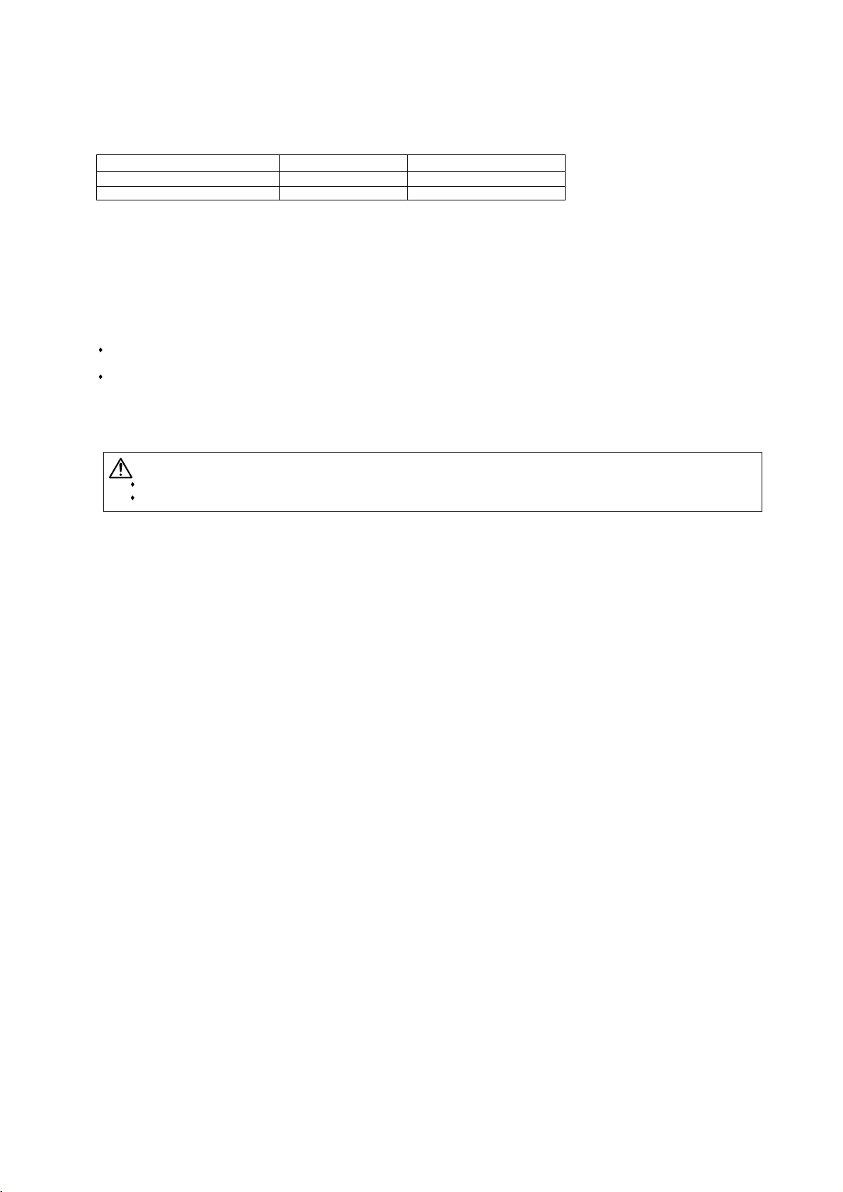
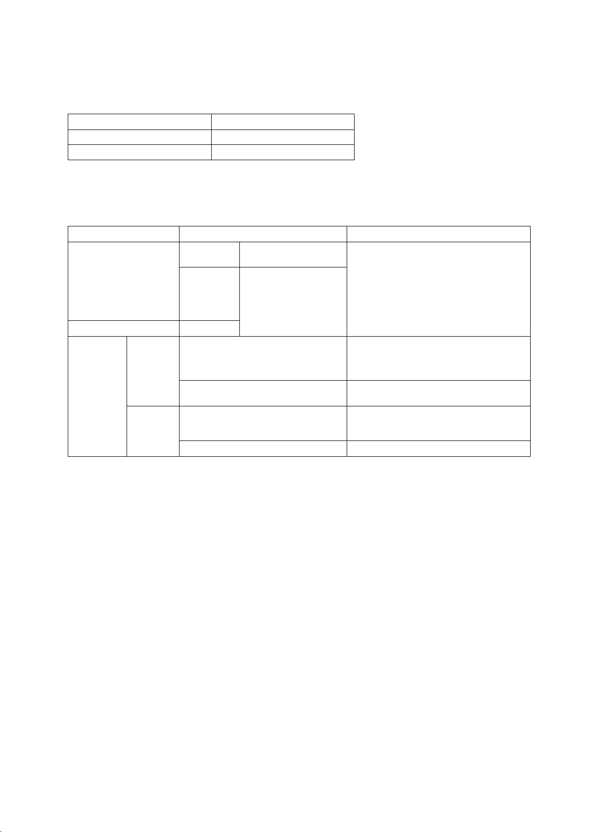
1. Check the type of refrigerant used in the system to be serviced.
Refrigerant Type
Between unit and BC controller
PWFY-P100VM-E-BU
Inside the unit
R410A
-
PWFY-P100, 200VM-E-AU
2. Check the symptoms exhibited by the unit to be serviced.
Refer to this service handbook for symptoms relating to the refrigerant cycle.
3. Thoroughly read the safety precautions at the beginning of this manual.
4. Preparing necessary tools: Prepare a set of tools to be used exclusively with each type of refrigerant.
Refer to "Necessary Tools and Materials" for information on the use of tools.(page 8)
5. Verification of the connecting pipes: Verify the type of refrigerant used for the unit to be moved or replaced.
Use refrigerant pipes made of phosphorus deoxidized copper. Keep the inner and outer surfaces of the pipes clean and free
of such contaminants as sulfur, oxides, dust, dirt, shaving particles, oil, and water.
These types of contaminants inside the refrigerant pipes may cause the refrigerant oil to deteriorate.
6. If there is a leak of gaseous refrigerant and the remaining refrigerant is exposed to an open flame, a poisonous gas
hydrofluoric acid may form. Keep workplace well ventilated.
CAUTION
Install new pipes immediately after removing old ones to keep moisture out of the refrigerant circuit.
The use of refrigerant that contains chloride, such as R22, will cause the refrigerating machine oil to deteriorate.
R410A
R134A
- 7 -
¡¡
Read Before Servicing
Page 11
[2] Necessary Tools and Materials
Prepare the following tools and materials necessary for installing and servicing the unit.
To ols for use with R410A (Adaptability of tools that are for use with R22 or R407C)
1. To be used exclusively with R410A (not to be used if used with R22 or R407C)
2. Tools and materials that may be used with R410A with some restrictions
3. Tools and materials that are used with R22 or R407C that may also be used with R410A
4. Tools and materials that must not be used with R410A
Tools for R410A must be handled with special care to keep moisture and dust from infiltrating the cycle.
setoNesUslairetaM/slooT
c tnaregirfer dna noitaucavEdlofinaM eguaG harging Higher than 5.09MPa[738psi] on the
high-pressure side
igrahc tnaregirfer dna noitaucavEesoH gnigrahC ng The hose diameter is larger than the
conventional model.
Refrigerant Recovery Cylinder Refrigerant recovery
hTgnigrahc tnaregirfeRrednilyC tnaregirfeR e refrigerant type is indicated. The
cylinder is pink.
Charging Port on the Refrigerant Cylinder Refrigerant chargingThe charge port diameter is larger
than that of the current port.
tiw tinu eht fo noitcennoCtuN eralFh the pipes Use Type-2 Flare nuts.
setoNesUslairetaM/slooT
noitceted kael saGrotceteD kaeL saG The ones for use with HFC refrigerant
may be used.
retpada evlav kcehc a fi desu eb yaMgniyrd muucaVpmuP muucaV
is attached.
eht rof snoisnemid gnissecorp eralFgnissecorp eralFlooT eralF
piping in the system using the new refrigerant differ from those of R22. Refer to next page.
Refrigerant Recovery Equipment Refrigerant recovery
May be used if compatible with R410A
or R134a
setoNesUslairetaM/slooT
Vacuum Pump with a Check Valve Vacuum drying
sepip gnidneBredneB
snoisnemid gnissecorp eralf eht ylnOstun eralf gninethgiThcnerW euqroT
for pipes that have a diameter of
ø12.70 (1/2") and ø15.88 (5/8") have
been changed.
sepip gnittuCrettuC epiP
Welder and Nitrogen Cylinder Welding pipes
Refrigerant Charging Meter Refrigerant charging
kcehc level muucaVeguaG muucaV
setoNesUslairetaM/slooT
esu ot detibihorPgnigrahc tnaregirfeRrednilyC gnigrahC
- 8 -
Page 12
[3] Piping Materials
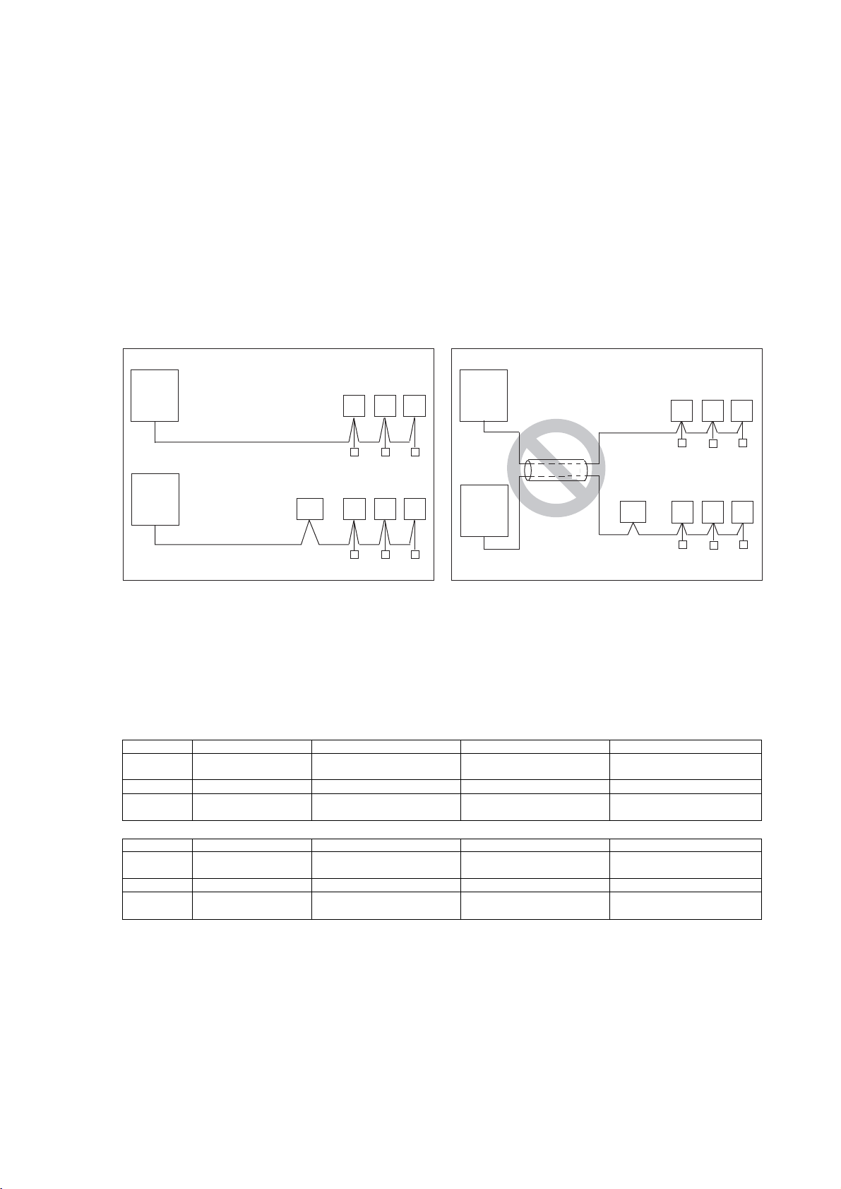
1. Copper pipe materials
The distinction between O-materials (Annealed) and 1/2H-materials (Drawn) is made based on the strength of the pipes them-
selves.
O-materials (Annealed) can easily be bent with hands.
1/2H-materials (Drawn) are considerably stronger than O-material (Annealed) at the same thickness.
2. Types of copper pipes
3. Piping materials/Radial thickness
Use refrigerant pipes made of phosphorus deoxidized copper.
The operation pressure of the units that use R410A is higher than that of the units that use R22.
Use pipes that have at least the radial thickness specified in the chart below.
(Pipes with a radial thickness of 0.7 mm or less may not be used.)
The pipes in the system that uses the refrigerant currently on the market are made with O-material (Annealed), even if the
pipe diameter is less than ø19.05 (3/4"). For a system that uses R410A, use pipes that are made with 1/2H-material (Drawn)
unless the pipe diameter is at least ø19.05 (3/4") and the radial thickness is at least 1.2t.
The figures in the radial thickness column are based on the Japanese standards and provided only as a reference. Use pipes
that meet the local standards.
O-material (Annealed) Soft copper pipes (annealed copper pipes). They can easily be bent with hands.
1/2H-material (Drawn) Hard copper pipes (straight pipes). They are stronger than the O-material (Annealed)
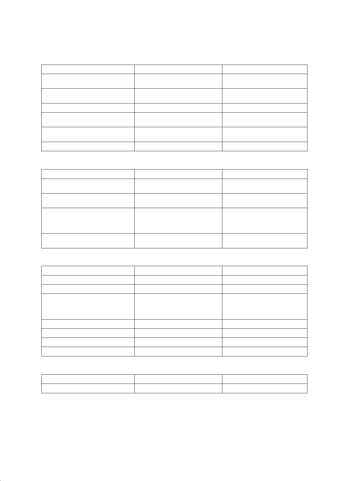
at the same radial thickness.
Maximum working pressure Refrigerant type
4.30 MPa [624psi] R410A and R134a
Pipe size (mm[in]) Radial thickness (mm) Type
ø6.35 [1/4"] 0.8t
O-material (Annealed)
ø9.52 [3/8"] 0.8t
ø12.7 [1/2"] 0.8t
ø15.88 [5/8"] 1.0t
ø19.05 [3/4"] 1.0t
1/2H-material,
H-material (Drawn)
ø22.2 [7/8"] 1.0t
ø25.4 [1"] 1.0t
ø28.58 [1-1/8"] 1.0t
ø31.75 [1-1/4"] 1.1t
ø34.93 [1-3/8"] 1.1t
ø41.28 [1-5/8"] 1.2t
Do not use the existing piping!
- 9 -
Page 13
- 10 -
4. Thickness and refrigerant type indicated on the piping materials
Ask the pipe manufacturer for the symbols indicated on the piping material for new refrigerant.
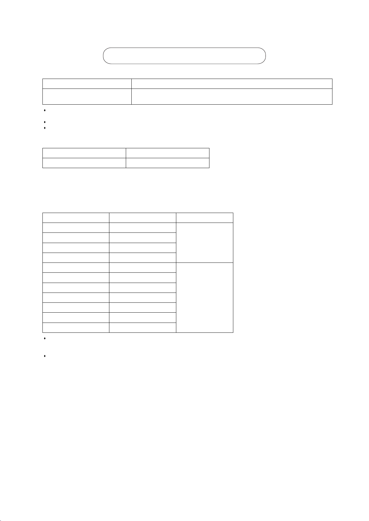
5. Flare processing (O-material (Annealed) and OL-material only)
The flare processing dimensions for the pipes that are used in the R410A system are larger than those in the R22 system.
If a clutch-type flare tool is used to flare the pipes in the system using R410A, the length of the pipes must be between 1.0
and 1.5 mm. For margin adjustment, a copper pipe gauge is necessary.
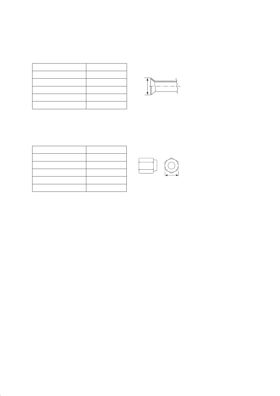
6. Flare nut
The flare nut type has been changed to increase the strength. The size of some of the flare nuts have also been changed.
The figures in the radial thickness column are based on the Japanese standards and provided only as a reference. Use pipes
that meet the local standards.
Flare processing dimensions (mm[in])
Pipe size (mm[in]) A dimension (mm)
ø6.35 [1/4"] 9.1
ø9.52 [3/8"] 13.2
ø12.7 [1/2"] 16.6
ø15.88 [5/8"] 19.7
ø19.05 [3/4"] 24.0
Flare nut dimensions (mm[in])
Pipe size (mm[in]) B dimension (mm)
ø6.35 [1/4"] 17.0
ø9.52 [3/8"] 22.0
ø12.7 [1/2"] 26.0
ø15.88 [5/8"] 29.0
ø19.05 [3/4"] 36.0
Dimension A
Dimension B
Page 14
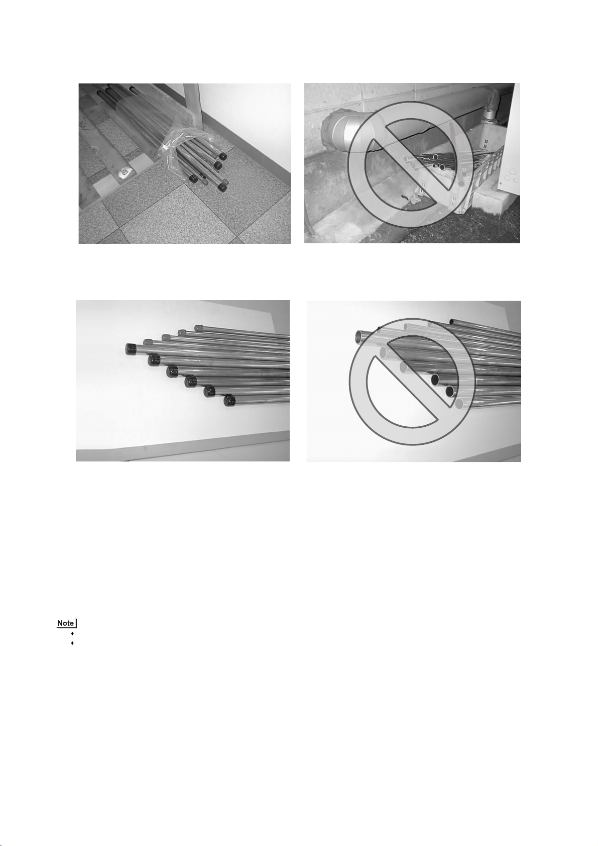
[4] Storage of Piping
1. Storage location
Store the pipes to be used indoors. (Warehouse at site or owner's warehouse)
If they are left outdoors, dust, dirt, or moisture may infiltrate and contaminate the pipe.
2. Sealing the pipe ends
Both ends of the pipes should be sealed until just before brazing.
Keep elbow pipes and T-joints in plastic bags.
The new refrigerator oil is 10 times as hygroscopic as the conventional refrigerating machine oil (such as Suniso) and, if not
handled with care, could easily introduce moisture into the system. Keep moisture out of the pipes, for it will cause the oil to
deteriorate and cause a compressor failure.
[5] Pipe Processing
Use a small amount of ester oil, ether oil, or alkylbenzene to coat flares and flanges.
Use a minimum amount of oil.
Use only ester oil, ether oil, and alkylbenzene.
- 11 -
Page 15
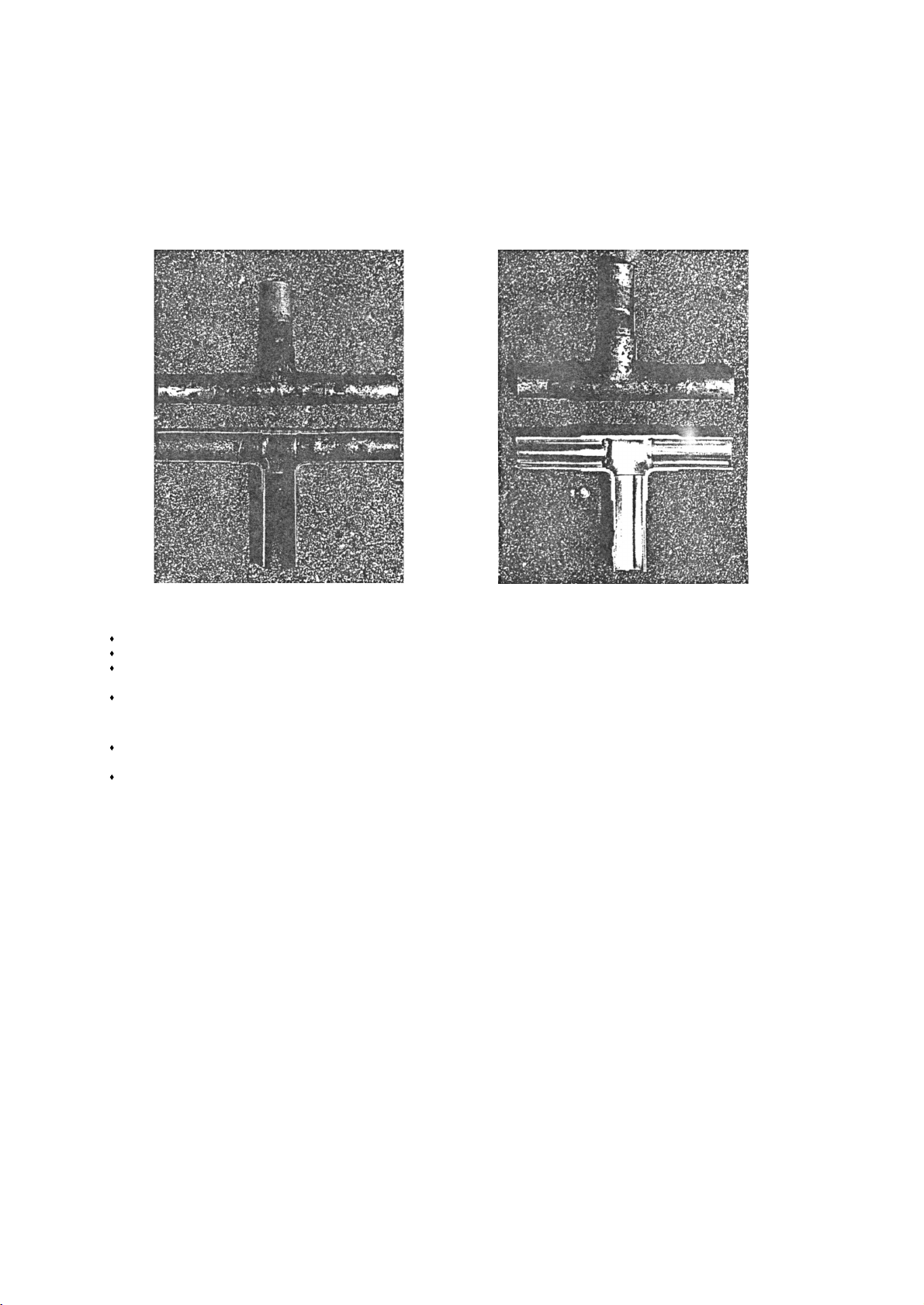
[6] Brazing
No changes have been made in the brazing procedures. Perform brazing with special care to keep foreign objects (such as oxide
scale, water, and dust) out of the refrigerant system.
Example: Inside the brazed connection
1. Items to be strictly observed
Do not conduct refrigerant piping work outdoors if raining.
Use non-oxidized solder.
Use a brazing material (BCuP-3) that requires no flux when brazing between copper pipes or between a copper pipe and
copper coupling.
If installed refrigerant pipes are not immediately connected to the equipment, then braze and seal both ends.
2. Reasons
The new refrigerating machine oil is 10 times as hygroscopic as the conventional oil and is more likely to cause unit failure if
water infiltrates into the system.
Flux generally contains chloride. Residual flux in the refrigerant circuit will cause sludge to form.
3. Notes
Do not use commercially available antioxidants because they may cause the pipes to corrode or refrigerating machine oil to
deteriorate.
esUgnizarb rof redlos dezidixo fo esU of non-oxidized solder for brazing
- 12 -
Page 16
[7] Air T ightness Test
No changes have been made in the detection method. Note that a refrigerant leak detector for R22 will not detect an R410A leak.
1. Items to be strictly observed
Pressurize the equipment with nitrogen up to the design pressure (4.15MPa[601psi]), and then judge the equipment's air tightness, taking temperature variations into account.
When using refrigerant instead of a leak detector to find the location of a leak, use R410A.
Refrigerant R410A must be charged in its liquid state (vs. gaseous state).
2. Reasons
Oxygen, if used for an air tightness test, poses a risk of explosion. (Only use nitrogen to check air tightness.)
Refrigerant R410A must be charged in its liquid state. If gaseous refrigerant in the cylinder is drawn out first, the composition
of the remaining refrigerant in the cylinder will change and become unsuitable for use.
3. Notes
Procure a leak detector that is specifically designed to detect an HFC leak. A leak detector for R22 will not detect an
HFC(R410A, R407C) leak.
rotceted egakael 22Rhcrot edilaH
- 13 -
Page 17
[8] Vacuum Drying (Evacuation)
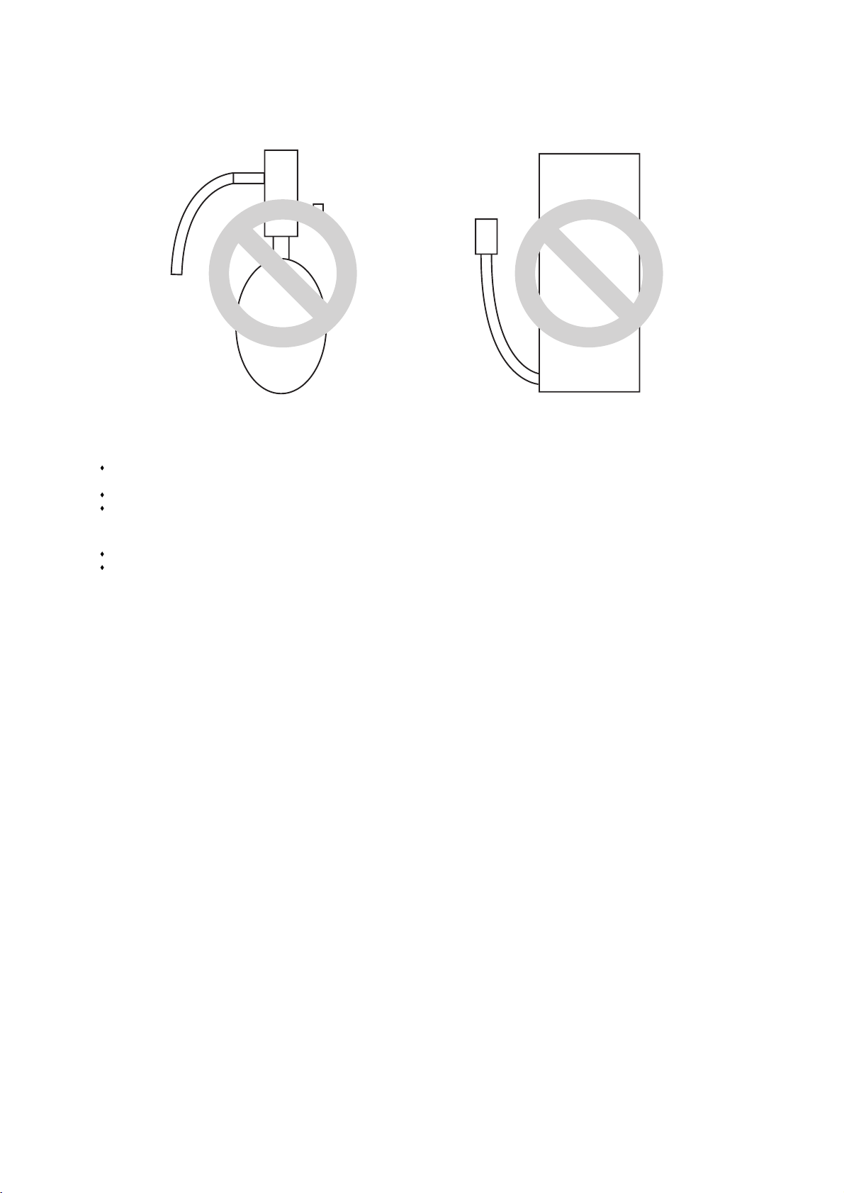
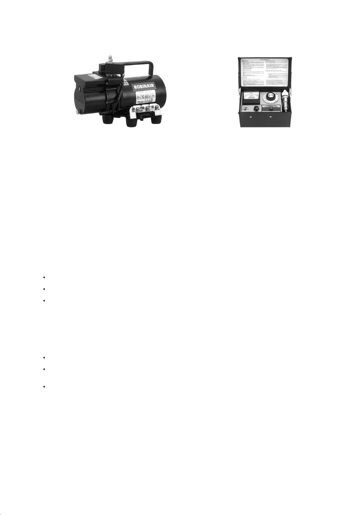
1. Vacuum pump with a reverse-flow check valve (Photo1)
To prevent the vacuum pump oil from flowing into the refrigerant circuit during power OFF or power failure, use a vacuum
pump with a reverse-flow check valve.
A reverse-flow check valve may also be added to the vacuum pump currently in use.
2. Standard of vacuum degree (Photo 2)
Use a vacuum pump that attains 0.5Torr(6 5Pa) or lower degree of vacuum after 5 minutes of operation, and connect it directly
to the vacuum gauge. Use a pump well-maintained with an appropriate lubricant. A poorly maintained vacuum pump may not
be able to attain the desired degree of vacuum.
3. Required precision of vacuum gauge
Use a vacuum gauge that registers a vacuum degree of 5Torr(650Pa) and measures at intervals of 1Torr(130Pa). (A recommended vacuum gauge is shown in Photo2.)
Do not use a commonly used gauge manifold because it cannot register a vacuum degree of 5Torr(650Pa).
4. Evacuation time
After the degree of vacuum has reached 5Torr(650Pa), evacuate for an additional 1 hour. (A thorough vacuum drying removes moisture in the pipes.)
Verify that the vacuum degree has not risen by more than 1Torr(130Pa) 1hour after evacuation. A rise by less than
1Torr(130Pa) is acceptable.
If the vacuum is lost by more than 1Torr(130Pa), conduct evacuation, following the instructions in section 6. Special vacuum
drying.
5. Procedures for stopping vacuum pump
To prevent the reverse flow of vacuum pump oil, open the relief valve on the vacuum pump side, or draw in air by loosening
the charge hose, and then stop the operation.
The same procedures should be followed when stopping a vacuum pump with a reverse-flow check valve.
6. Special vacuum drying
When 5Torr(650Pa) or lower degree of vacuum cannot be attained after 3 hours of evacuation, it is likely that water has penetrated the system or that there is a leak.
If water infiltrates the system, break the vacuum with nitrogen. Pressurize the system with nitrogen gas to
0.5kgf/cm
2
G(0.05MPa) and evacuate again. Repeat this cycle of pressurizing and evacuation either until the degree of vac-
uum below 5Torr(650Pa) is attained or until the pressure stops rising.
Only use nitrogen gas for vacuum breaking. (The use of oxygen may result in an explosion.)
01041 )2otohP(H01051 )1otohP(
Recommended vacuum gauge:
ROBINAIR 14010 Thermistor Vacuum Gauge
- 14 -
Page 18
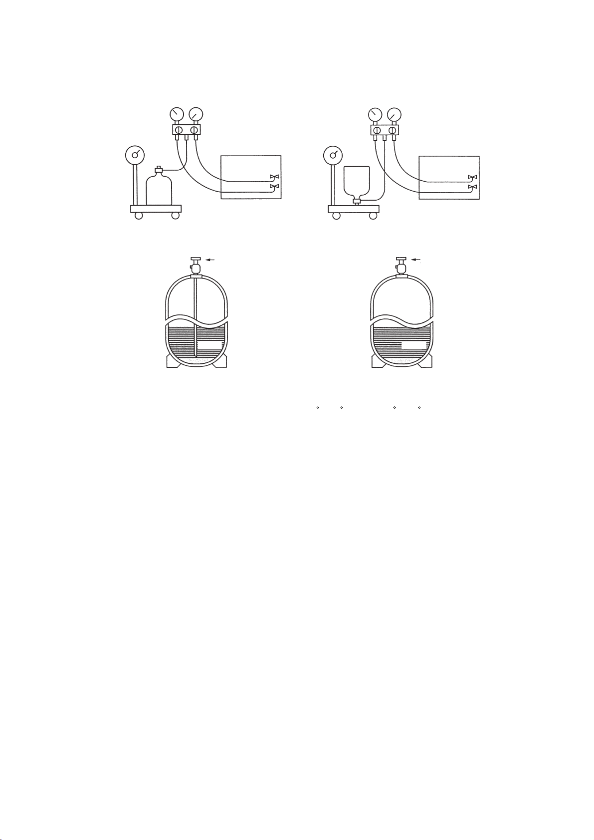
[9] Refrigerant Charging
1. Reasons
R410A is a pseudo-azeotropic HFC blend (boiling point R32=-52 C[-62 F], R125=-49 C [-52 F]) and can almost be handled
the same way as a single refrigerant, such as R22. To be safe, however, draw out the refrigerant from the cylinder in the liquid
phase. If the refrigerant in the gaseous phase is drawn out, the composition of the remaining refrigerant will change and become unsuitable for use.
2. Notes
When using a cylinder with a siphon, refrigerant is charged in the liquid state without the need for turning it upside down. Check
the type of the cylinder on the label before use.
[10] Remedies to be taken in case of a Refrigerant Leak
If the refrigerant leaks out, it may be replenished. The entire refrigerant does not need to be replaced. (Charge refrigerant in the
liquid state.)
Cylinder with a siphon
etats diuqil eht ni gnigrahc tnaregirfeR.knip si A014R roloc rednilyC
Cylinder
liquid
evlaVevlaV
liquid
Cylinder
Cylinder without a siphon
- 15 -
Page 19
[11] Characteristics of the Conventional and the New Refrigerants
1. Chemical property
As with R22, refrigerants R410A and R134A are low in toxicity and chemically stable nonflammable refrigerants.
However, because the specific gravity of vapor refrigerant is greater than that of air, leaked refrigerant in a closed room will
accumulate at the bottom of the room and may cause hypoxia.
If exposed to an open flame, refrigerant will generate poisonous gases. Do not perform installation or service work in a confined area.
*1 When CFC11 is used as a reference
*2 When CO
2
is used as a reference
2. Refrigerant composition
R410A is a pseudo-azeotropic HFC blend and can almost be handled the same way as a single refrigerant, such as R22. To
be safe, however, draw out the refrigerant from the cylinder in the liquid phase. If the refrigerant in the gaseous phase is drawn
out, the composition of the remaining refrigerant will change and become unsuitable for use.
If the refrigerant leaks out, it may be replenished. The entire refrigerant does not need to be replaced.
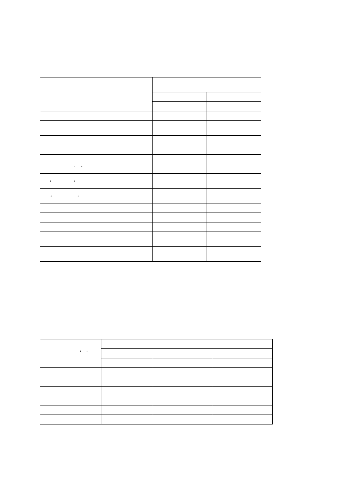
3. Pressure characteristics
R410A has slightly higher operating pressure compared with R22.
New Refrigerant (HFC type)
R410A
R32/R125
)05/05()%tw( noitisopmoC
ciportoeza-oduesPtnaregirfeR fo epyT
Refrigerant
dedulcni toNedirolhC
1A/1AssalC ytefaS
6.27thgieW raluceloM
-/4.15-)F/C( tnioP gnilioB 60.5
Steam Pressure
(25 C,MPa/77 F,psi) (gauge)
1.557/226
Saturated Steam Density
(25 C,kg/m
3
/77 F, psi)
64.0
elbammalfnoNytilibammalF
Ozone Depletion Coefficient (ODP)
*1
0
Global Warming Coefficient (GWP)
*2
1730
Refrigerant Charging Method Refrigerant charging in
the liquid state
Replenishment of Refrigerant after a Refrigerant
Leak
Available
Temperature ( C/ F )
Pressure (gauge)
R410A R134a R22
MPa/psi MPa/psi MPa/psi
-20/-4 0.30/44 0.13/19 0.14/20
0/32 0.70/102 0.29/42 0.40/58
20/68 1.34/194 0.57/83 0.81/117
40/104 2.31/335 1.02/148 1.44/209
60/140 3.73/541 1.68/244 2.33/338
65/149 4.17/605 1.89/274 2.60/377
R134a
R134a
(100)
Single-
Refrigerant
Not contained
A1/A1
102.0
-26.1/-15.0
0.67/97
32.3
Non-flammable
0
1300
Liquid charging
Possible
- 16 -
Page 20
- 17 -
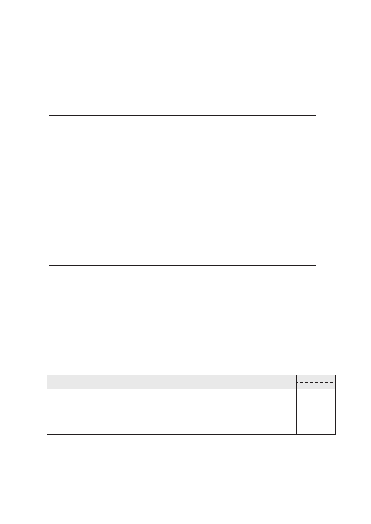
[12] Notes on Refrigerating Machine Oil
1. Refrigerating machine oil in the HFC refrigerant system
HFC type refrigerants use a refrigerating machine oil different from that used in the R22 system.
Note that the ester oil used in the system has properties that are different from commercially available ester oil.
2. Effects of contaminants
*1
Refrigerating machine oil used in the HFC system must be handled with special care to keep contaminants out.
The table below shows the effect of contaminants in the refrigerating machine oil on the refrigeration cycle.
3. The effects of contaminants in the refrigerating machine oil on the refrigeration cycle.
Refrigerant Refrigerating machine oil
HAB
Ester oil
R134a
R410A
*1.Contaminants is defined as moisture, air, processing oil, dust/dirt, wrong types of refrigerant, and refrigerating machine oil.
stceffEsmotpmySesuaC on the refrigerant cycle
evlav noisnapxe nezorFnoitartlifni retaW
and capillary tubes
Clogged expansion valve and capillary tubes
Poor cooling performance
Compressor overheat
Motor insulation failure
Burnt motor
Coppering of the orbiting scroll
Lock
Burn-in on the orbiting scroll
Hydrolysis
Sludge formation and adhesion
Acid generation
Oxidization
Oil degradation
Air infiltration Oxidization
Infiltration of
contaminants
Dust, dirt
Adhesion to expansion valve and capillary
tubes
Clogged expansion valve, capillary tubes, and
drier
Poor cooling performance
Compressor overheat
Infiltration of contaminants into the compressor
Burn-in on the orbiting scroll
Mineral oil
etc.
Sludge formation and adhesion Clogged expansion valve and capillary tubes
Poor cooling performance
Compressor overheat
llorcs gnitibro eht no ni-nruBnoitadarged liO
Page 21
Unit Unit
Unit
Remote
BC controller
controller
2-core cable
2-core cable
Remote
controller
Unit
Multiple-
core cable
BC controller
PWFY-P100VM-E-BU
Type of cable
Cable diameter
Remarks
Transmission cables
Shielding wire (2-core)
CVVS, CPEVS or MVVS
More than 1.25 mm
2
-
MA Remote controller cables
Sheathed 2-core cable (shielded)
CVVS
0.3 ~ 1.25 mm2 (0.75 ~ 1.25 mm2)*1
Max.length: 200 m
External input
Sheathed multi-core cable (shielded)
CVVS or MVVS
0.3 ~ 0.5 mm
2
Max.length: 100 m
External output
Sheathed multi-core cable (unshielded)
CVV or MVV
0.3 ~ 1.25 mm
2
Rated voltage: L1-N: 220 ~
240 V
Rated load: 0.6 A
PWFY-P100/200VM-E-AU
Type of cable
Cable diameter
Remarks
Transmission cables
Shielding wire (2-core)
CVVS, CPEVS or MVVS
More than 1.25 mm
2
-
MA Remote controller cables
Sheathed 2-core cable
CVV (unshielded)
0.3 ~ 1.25 mm2 (0.75 ~ 1.25 mm2)*1
Max.length: 200 m
External input
Sheathed multi-core cable
CVV or MVV (unshielded)
0.3 ~ 0.5 mm
2
Max.length: 100 m
External output
Sheathed multi-core cable (unshielded)
CVV or MVV
0.3 ~ 1.25 mm
2
Rated voltage: L1-N: 220 ~
240 V
Rated load: 0.6 A
*1 Connected with simple remote controller. CVVS, MVVS: PVC insulated PVC jacketed shielded control cable
CVV, MVV
: PVC insulated PVC sheathed control cable
CPEVS :
PE insulated PVC jacketed shielded communication cable
[1] Types and Maximum allowable Length of Cables
1. Wiring work
(1) Notes
1) Have all electrical work performed by an authorized electrician according to the local regulations and instructions in this manual.
2) Install external transmission cables at least 5cm [1-31/32"] away from the power supply cable to avoid noise interference.
(Donot put the control cable and power supply cable in the same conduit tube.)
3) Provide grounding for the outdoor unit as required.
4) Run the cable from the electric box of the indoor or outdoor unit in such way that the box is accessible for servicing.
5) Do not connect power supply wiring to the terminal block for transmission line. Doing so will damage the electronic components on the terminal block.
6) Use 2-core shielded cables as transmission cables.
Use a separate 2-core control cable for each refrigerant system. Do not use a single multiple-core cable to connect indoor
units that belong to different refrigerant systems. The use of a multiple-core cable may result in signal transmission errors and
malfunctions.
(2) Control wiring
Types and maximum allowable length of cables
Control lines are categorized into 2 types: transmission line and remote controller line.
Use the appropriate type of cables and observe the maximum allowable length specified for a given system. If a given system
has a long transmission line or if a noise source is located near the unit, place the unit away from the noise source to reduce
noise interference.
- 18 -
™™
Restrictions
Page 22
00
Main
00
Address (1) setting varies depending on the system configuration. See “[3] Examples of system connection”
section for details.
Unit or controller
Address
Setting method
setting range
Unit Main/sub units
MA remote controller
Outdoor unit
0, 01~50
(Note 1)
0, 51~100
(Note 1, 2, 3)
52~100
(Note 2, 3)
Factory
setting
Type and method of switch setting
Switch setting vary depending on the system configuration. Make sure to read “[3] Examples of system connection”
before conducting electrical work. Turn off the power before setting the switch. Operating the switch while the unit is
being powered will not change the setting, and the unit will not properly function.
Notes:
1. Address setting is not required for a single refrigerant system (with a few exception).
2. When setting the unit and outdoor auxiliary unit address to “100,” make it “50.”
3. When an address in a system overlapped with the heat source unit or BC controller (Main) address of other refrigerant system,
choose an another address within the set range that is not in use (with a few exceptions).
4. BC controller is found only in the R2 systems.
Use the address that equals the sum of the smallest indoor
unit address in the same refrigerant system and 50.
Use the address that equals the sum of the smallest
address of the indoor unit out of all the indoor units
that are connected to the BC controller and 50.
When a sub BC controller is connected, the automatic
start up function will not be available.
Auxiliary
units
BC controller (Sub)
Use the address that equals the sum of the address of the
heat source unit in the same refrigerant system and 1.
BC controller (Main)
Assign the smallest address to the indoor unit to
become the main unit within the same group, and
then use sequential numbers to assign an address
to all the indoor units in the group.
If applicable, set the sub BC controllers in an R2
system in the following order:
(1)
Indoor unit to be connected to the main BC controller
(2)
Indoor unit to be connected to No.1 sub BC controller
(3)
Indoor unit to be connected to No.2 sub BC controller
Set the address so that (1) < (2) < (3)
No address setting required. (When operating with 2 remote controllers,
the main/sub selector switch must be set.
Various start-stop controls (Unit settings)
Each unit (or group of units) can be controlled individually by setting SW 1-3 and 1-4.
(3)
Unit port switch setting (R2 series (Factory Setting: “0”))
Make the settings for the port switch that corresponds to the connected BC (Main/Sub) controller.
When more than two ports are used, make the setting on the port with a smaller port number.
(2)
Operation of the indoor unit when the operation is resumed after the unit was stopped
Function
Setting (SW1) (Note 2)
Power ON/OFF by the
plug (Note 1)
Unit will go into operation regardless of its operation status before power off
(power failure). (In approx. 5 minutes)
Unit will remain stopped regardless of its operation status before power off
(power failure).
Unit will go into operation if it was in operation when the power was turned off
(or cut off due to power failure). (In approx. 5 minutes)
34
OFF OFF
ON ON
OFF ON
(Note 1) Do not cut off power to the outdoor unit.
Cutting off the power supply to the outdoor unit will cut off the power supply to the crankcase heater and may cause the
compressor to malfunction when the unit is put back into operation.
(Note 2) Requires that the dipswitch settings for all the units in the group be made.
Automatic restoration
after power failure
- 19 -
[2] Types of Switch Setting and Address Setting
1. Switch setting
2. Address setting
Page 23
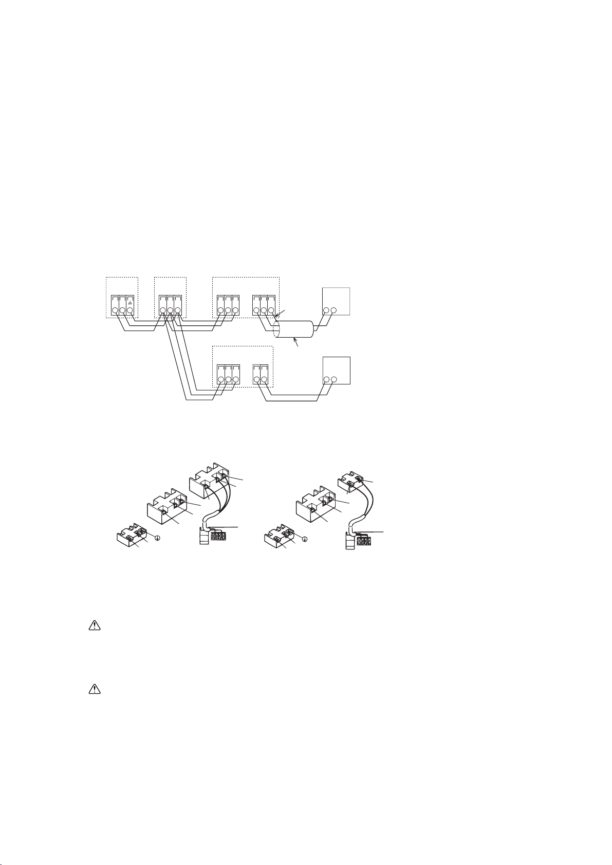
• Connect the “1” and “2” on unit TB15 to a MA remote controller. (Non-polarized 2-wire)
MA Remote controller
TB02
TB15
earth cable
(shielded)
TB5
SM1M2 SM1M2
TB3
M1M2
(A) (B) (C)
(D)
(E)
(E)
1 2S
TB15TB5
SM1M2 1 2
(shielding wire)
(A) Outdoor unit
(B) BC controller
(C) PWFY-P100VM-E-BU
(D) PWFY-P100, 200VM-E-AU
(E) MA remote controller
• DC 10 to 13 V between 1 and 2 (MA remote controller)
• The MA remote controller cannot be used at the same time or interchangeably.
Note:
Ensure that the wiring is not pinched when fitting the terminal box cover. Pinching the wiring may cut it.
Caution:
• Use wire with supplemental insulation.
• Input to TB142A, TB142B, and TB142C should not carry voltage.
• Cables from equipment connected to external input/output should have supplemental insulation.
• Use a single multiple-core cable for external input/output to allow for connection to the PG screw.
Caution:
Wire the power supply so that no tension is imparted. Otherwise disconnection, heating or fire result.
(B)
(A)
S
2
1
L
N
DC10~13V
12
AB
(C)
S
M2
M1
(D)
(E)
2
S
M2
M1
(A)
(B)
(D)
(E)
1
L
N
DC10~13V
AB
12
(C)
(A) Non-polarized
(B) TB15 (MA remote controller cables)
(C) MA remote Controller
(D) TB5 (Transmission cables)
(E) TB2 (Power supply wiring)
PWFY- P100VM-E-BU PWFY- P100, 200VM-E-AU
- 20 -
[3] Examples of system connection
1. Connecting remote controller, indoor and outdoor transmission cabls
• Connect unit TB5 and outdoor unit TB3. (Non-polarized 2-wire (shield))
The “S” on unit TB5 is a shielding wire connection. For specifications about the connecting cables, refer to
the outdoor unit installation manual.
• Install a remote controller following the manual supplied with the remote controller.
2. System using MA remote controller
(1) In the case of single refrigerant system (Automatic address set-up)
[4] Restrictions on piping length
The same piping length restrictions apply as the ones that apply to the conventional indoor units.
Refer to the Service Manual that came with the outdoor unit for restrictions on piping length.
Design the water piping system so that the total amount of water held in the system is 100 liter or less.
Page 24
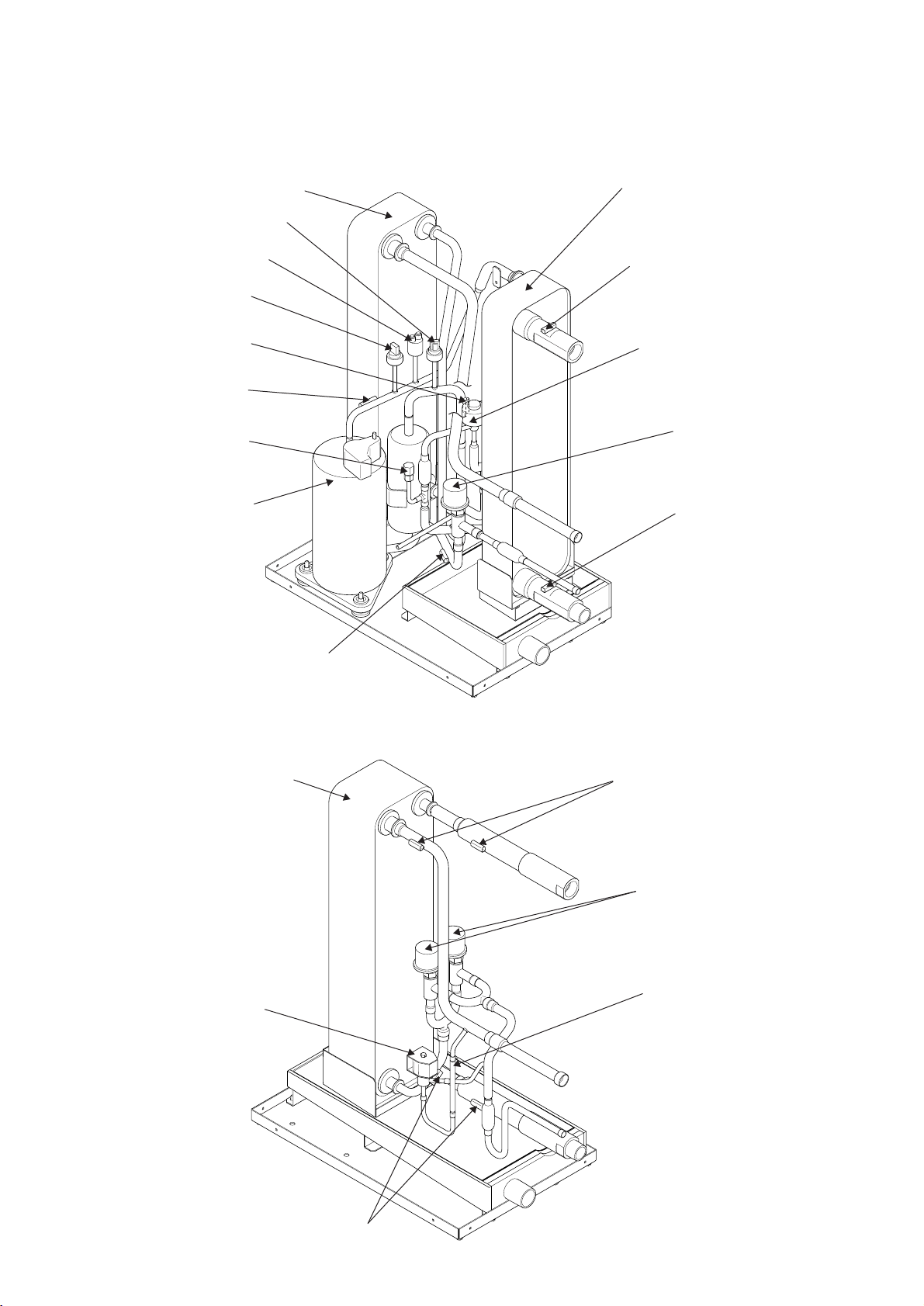
Heat exchanger assy
Pressure sensor (63LS)
Pressure switch (63H1)
Pressure sensor (63HS)
Thermistor (TH11)
Check joint
Compressor
Heat exchanger assy
Linear expansion valve
Linear expansion valve coil
(LEV2W)
Linear expansion valve
(LEV1W)
Thermistor (TH8)
Thermistor (TH6)
Thermistor (TH22)
Thermistor (TH13)
- 21 -
££
Components of the Unit
[1] Appearance of the Components and Refrigerant Circuit
< PWFY-P100VM-E-BU >
Heat exchanger assy
Solenoid valve
Solenoid valve coil (SV)
Thermistor (TH6,TH22)
Check valve
Linear expansion valve
(LEV1Wa,b)
Thermistor (TH8,TH23)
< PWFY-P100, 200VM-E-AU >
Page 25
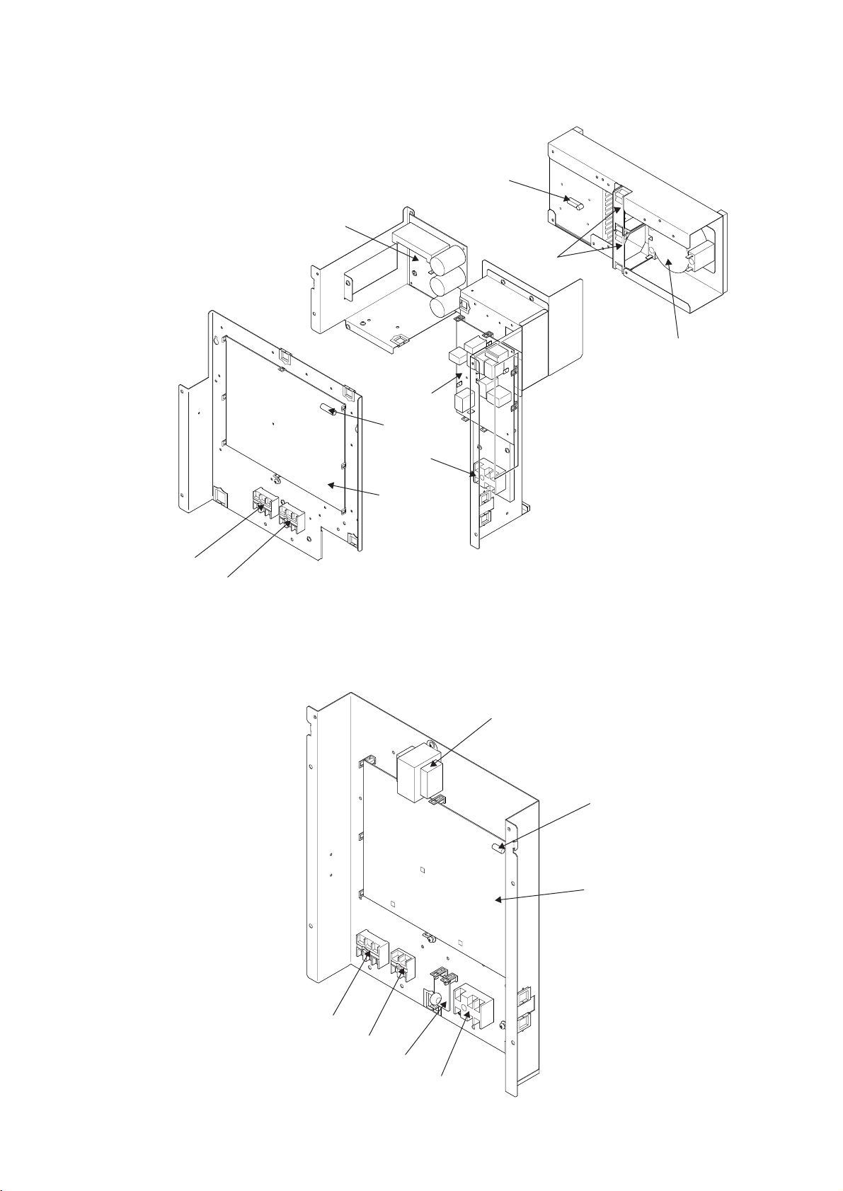
- 22 -
Thermistor (THHS)
INV board
Fan
Noise filter
Te r minal block
(TB2)
Te r minal block
(TB5)
Te r minal block (TB15)
Control board
Fuse
Reactor
Tr ansformer
Fuse
Control board
Te r minal block assy (TB5)
Te r minal block assy (TB15)
DSA board
Te r minal block assy
(TB2)
[2] Control Box
< PWFY-P100VM-E-BU >
< PWFY-P100, 200VM-E-AU >
Page 26
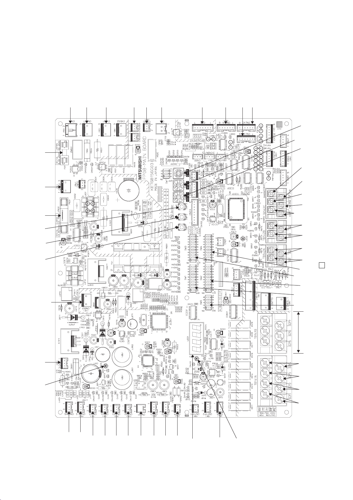
- 23 -
TB141A
(OUT1)
TB141A, TB142A, TB142B, TB142C : Refer to 5 Electrical Wiring Diagram
TB142A
(IN1)
TB142A
(IN2)
TB142B
(IN3)
TB142B
(IN4)
TB142C
(IN5)
TB142C
(IN6)
TB142C
(IN7)
TB142C
(IN8)
TB142C
(COM
+
)
TB141B
SW5 SW1 SW3
SW2 SW4
SWU1
SWU2
CNLVC
CNLVB
CNLVA
CN2
CN4
CN52C
CN506A,B
CN501
CN507
CNAC
F01CN631CN661
(63H1)
F631SWP3SWP2SWP1CN3TLED3
LED4
LED1
CN2M
CN422
CN421
CN401
CN402
CN403
CN404
CN405
CN63LS
CN63HS
CN3A
SWU3
TB141A
(OUT2)
TB141A
(OUT3)
TB141A
(OUT4)
[3] Circuit Board
1. Main board
< PWFY-P100VM-E-BU, PWFY-P100, 200VM-E-AU >
Page 27
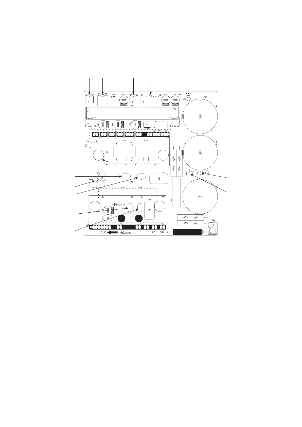
- 24 -
CN5
U
V
LD9
LD2
LD1
W
R
S
CN4 CN3 CN2
2. Power board
< PWFY-P100VM-E-BU >
Page 28
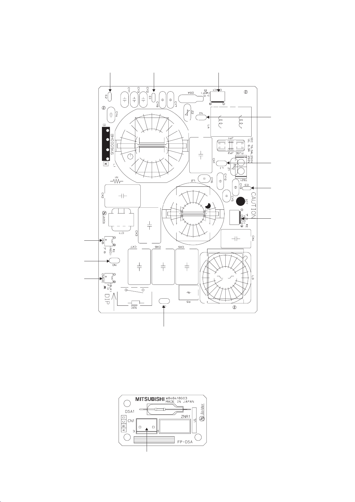
- 25 -
CN5
CN52C
LO
CNAC2
E3
LI
NI
E2 E1 CNAC1
NO
3. Noise filter
CN1
4. DSA
< PWFY-P100VM-E-BU >
< PWFY-P100,200VM-E-AU >
Page 29

- 26 -
Function/specification
Remote controller address setting Not required
Indoor/outdoor unit address setting Not required (required only by a system with one outdoor unit)
Wiring method Non-polar 2 wires
✻ Daisy-chain the units with non-polar 2 wires when running
a group operation.
Installation location of remote controller Connectable to any unit in the group
Making group changes MA remote controller wires between units require rewiring.
MA remote controller
¢¢
Remote Controller
[1] Functions and Specifications of MA Remote Controller
MA remote controller is connected to each unit.
Page 30
- 27 -
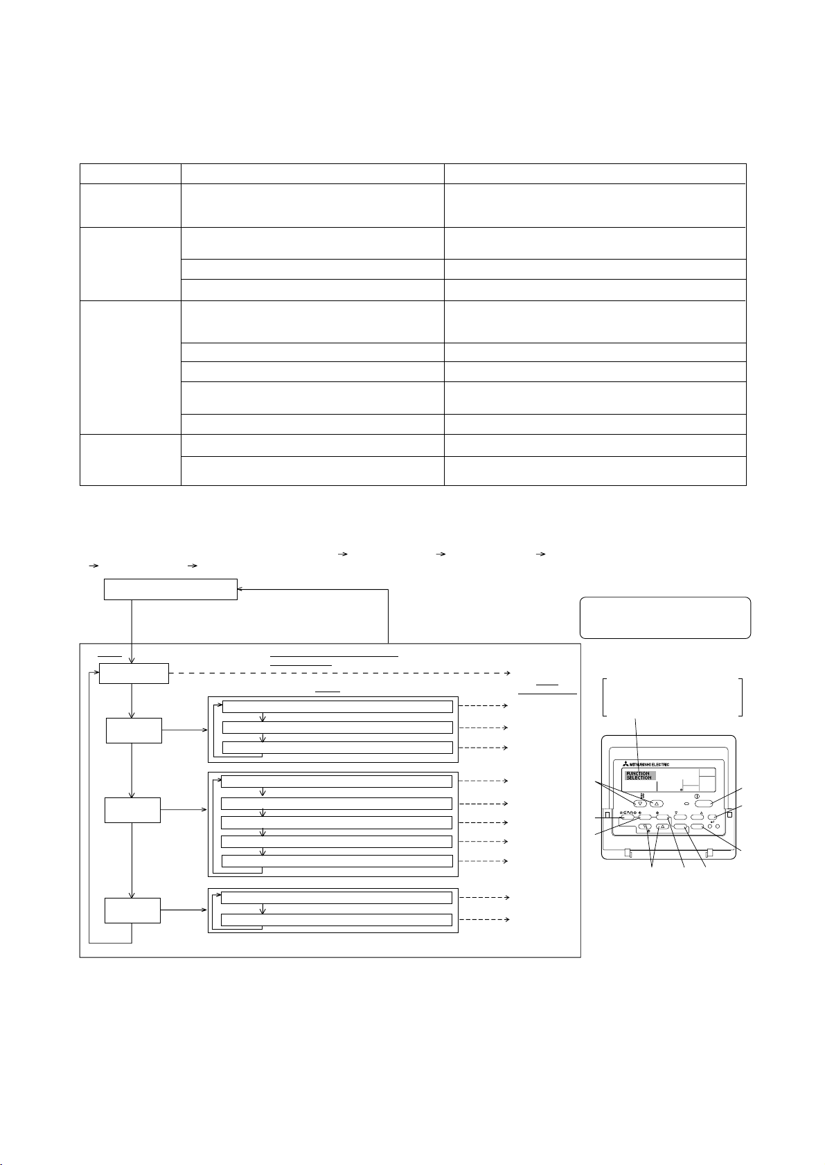
[2] Interlocking Setting via the MA Remote Controller
1. Remote controller function selection via the MA remote controller
Item 3 (Setting content)
• Display in multiple languages is possible
• Setting the range of operation limit (operation lock)
• Setting the use or non-use of each operation mode
• Setting the temperature adjustable range (maximum, minimum)
• Selecting main or sub remote controller
* When two remote controllers are connected to one group, one
controller must be set to sub.
• Setting the use or non-use of clock function
• Setting the timer type
• Contact number display in case of error
• Setting the telephone number
• Setting the use or non-use of setback amount setting
• Setting the temperature unit (
˚C or ˚ F) to display
• Setting the use or non-use of the display of water temperature
Function selection of remote controller
The setting of the following remote controller functions can be changed using the remote controller function selection mode. Change the setting when needed.
Item 1
1. Change Language
(“CHANGE
LANGUAGE”)
2. Function limit
(“FUNCTION
SELECTION”)
3. Mode selection
(“MODE SELECTION”)
4. Display change
(“DISP MODE
SETTING”)
Item 2
Language setting to display
(1) Operation function limit setting (operation lock) (“LOCKING
FUNCTION”)
(2) Operation mode skip setting (“SELECT MODE”)
(3) Temperature range limit setting (“LIMIT TEMP FUNCTION”)
(1) Remote controller main/sub setting (“CONTROLLER MAIN/
SUB”)
(2) Use of clock setting (“CLOCK”)
(3) Timer function setting (“WEEKLY TIMER”)
(4) Contact number setting for error situation (“CALL.”)
(5) Temp off set setting (“TEMP OFF SET FUNCTION”)
(1) Temperature display
˚C/˚ F setting (“TEMP MODE ˚C/˚ F”)
(2) Water temperature display setting (“WATER TEMP DISP
SELECT”)
(Hold down the E button and press the D button for two
seconds.)
* The display cannot be changed during the test run and
the self diagnosis.
(Hold down the E button and press
the D button for two seconds.)
* The remote controller records the
setting that is made in this way.
Press the
G button.
See [3]–1
Item 3
(Setting content)
See [3]–2. (1)
See [3]–2. (2)
See [3]–2. (3)
See [3]–3. (1)
See [3]–3. (2)
See [3]–3. (3)
See [3]–3. (4)
See [3]–3. (5)
See [3]–4. (1)
See [3]–4. (2)
Item 1 Remote Controller Function
Selection Mode
Item 2
Normal display (Display when
the unit is not running)
Change Language
(“CHANGE LANGUAGE”)
Function limit
(“FUNCTION
SELECTION”)
NOTE
Timer operation stops when the display for
remote controller function selection is
changed to the normal one.
Press the G button.
Press the
E button.
Press the
D button.
Operation function limit setting (“LOCKING FUNCTION”)
Press the G button.
Temperature range limit setting (“LIMIT TEMP FUNCTION”)
Dot display
The language that is selected in
CHANGE LANGUAGE mode appears on this display. English is
set in this manual.
Mode selection
(“MODE
SELECTION”)
Display change
(“DISP MODE
SETTING”)
Press the
E button.
Press the
E button.
Press the
E button.
Press the
G button.
Press the
G button.
Operation mode skip setting (“SELECT MODE”)
Press the
D button.
Temperature display ˚C/˚F setting (“TEMP MODE ˚C/˚F”)
Press the G button.
Water temperature display setting (“WATER TEMP DISP SELECT”)
Press the
D button.
Remote controller main/sub setting (“CONTROLLER MAIN/SUB”)
Press the G button.
Timer function setting (“WEEKLY TIMER”)
Use of clock setting (“CLOCK”)
Temp off set setting (“TEMP OFF SET FUNCTION”)
Contact number setting for error situation (“CALL.”)
Function selection flowchart
[1] Stop the unit to start remote controller function selection mode. [2] Select from item 1. [3] Select from item 2. [4] Make the setting. (Details are specified in item
3) [5] Setting completed. [6] Change the display to the normal one. (End)
F
TEMP.
MENU
ON/OFF
E
BACK DAY
PAR-W21MAA
G
MONITOR/SET
CLOCK CLEAR
C
INITIAL SETTING
CHECK TEST
D
ON/OFF
CIR.WATER
H
I
A
B
Page 31

- 28 -
Detailed setting
[3]–1. CHANGE LANGUAGE setting
The language that appears on the dot display can be selected.
• Press the [
MENU] button to change the language.
1 English (GB), 2 German (D), 3 Spanish (E), 4 Russian (RU),
5 Italian (I), 6 French (F), 7 Swedish
[3]–2. Function limit
(1) Operation function limit setting (operation lock)
• To switch the setting, press the [
ON/OFF] button.
1 no1 : Operation lock setting is made on all buttons other than the
[
ON/OFF] button.
2 no2 : Operation lock setting is made on all buttons.
3 OFF (Initial setting value) : Operation lock setting is not made.
* To make the operation lock setting valid on the normal screen, it is necessary to
press buttons (Press and hold down the [CIR.WATER] and [
ON/OFF] buttons
at the same time for two seconds.) on the normal screen after the above setting
is made.
(2) Operation mode skip setting
After setting is changed, the operation mode can not be changed within the changed
range.
• To switch the following settings, press the [
ON/OFF] button.
1 Heating mode : Sets the use or non-use of the Heating mode.
2 Heating ECO mode : Sets the use or non-use of the Heating ECO
mode.
3 Hot Water mode : Sets the use or non-use of the Hot Water mode.
4 Anti-freeze mode : Sets the use or non-use of the Anti-freeze
mode.
5 Cooling mode : Sets the use or non-use of the Cooling mode.
6 OFF (Initial setting value) : Operation mode skip is not executed.
* When the setting, other than OFF, is made, the skip settings of the Heating,
Heating ECO, Hot Water, Anti-freeze, and Cooling modes are executed at the
same time.
*A mode that is not available on the unit to connect cannot be used even if the
setting is “AVAILABLE.”
(3) Temperature range limit setting
After this setting is made, the temperature can be changed within the set range.
• To switch the setting, press the [
ON/OFF] button.
1 LIMIT TEMP HEATING MODE:
The temperature range can be changed on heating mode.
2 LIMIT TEMP HOT WATER MODE:
The temperature range can be changed on heating/hot water mode.
3 LIMIT TEMP ANTI-FREEZE MODE:
The temperature range can be changed on anti-freeze mode.
4 LIMIT TEMP COOLING MODE:
The temperature range can be changed on cooling mode.
5 OFF (Initial setting) : The temperature range limit is not active.
* When the setting, other than OFF, is made, the temperature range limit setting
on hot water, anti-freeze and cooling mode is made at the same time. However,
the range cannot be limited when the set temperature range has not changed.
• To increase or decrease the temperature, press the [
TEMP. or ]
button.
• Settable range
Hot Water mode : Lower limit: 30 ~70
˚C (87 ~158 ˚F)
Upper limit: 70 ~30
˚C (158 ~ 87 ˚ F)
Heating mode : Lower limit: 30 ~45
˚C (87 ~113 ˚F)
Upper limit: 45 ~30
˚C (113 ~ 87 ˚ F)
Cooling mode : Lower limit: 10 ~30
˚C (50 ~ 87 ˚F)
Upper limit: 30 ~10
˚C (87 ~ 50 ˚F)
* The settable range varies depending on the unit to connect.
[3]–3. Mode selection setting
(1) Remote controller main/sub setting
• To switch the setting, press the [
ON/OFF] button D.
1 Main : The controller will be the main controller.
2 Sub : The controller will be the sub controller.
(2) Use of clock setting
• To switch the setting, press the [
ON/OFF] button D.
1 ON : The clock function can be used.
2 OFF : The clock function cannot be used.
(3) Timer function setting
• To switch the setting, press the [
ON/OFF] button D (Choose one of the
followings.).
1 WEEKLY TIMER (Initial setting value): The weekly timer can be used.
2 AUTO OFF TIMER : The auto off timer can be used.
3 SIMPLE TIMER : The simple timer can be used.
4 TIMER MODE OFF : The timer mode cannot be used.
* When the use of clock setting is OFF, the “WEEKLY TIMER” cannot be used.
(4) Contact number setting for error situation
• To switch the setting, press the [
ON/OFF] button D.
1 CALL OFF : The set contact numbers are not displayed in case of error.
2 CALL **** *** **** : The set contact numbers are displayed in case of error.
CALL_ : The contact number can be set when the display is as
shown on the left.
• Setting the contact numbers
To set the contact numbers, follow the following procedures.
Move the flashing cursor to set numbers. Press the [
TEMP. or
] button F to move the cursor to the right (left). Press the [ CLOCK
or ] button C to set the numbers.
(5) Temp off see. setting
• To switch the following settings, press the [
ON/OFF] button D.
1 ON : The setback amount setting is displayed under the water temperature
initial setting mode.
2 OFF : The setback amount setting is not displayed under the water tempera-
ture initial setting mode.
[3]–4. Display change setting
(1) Temperature display ˚C/˚ F setting
• To switch the setting, press the [
ON/OFF] button D.
1 ˚C: The temperature unit
˚C is used.
2 ˚F: The temperature unit
˚F is used.
(2) Water temperature display setting
• To switch the setting, press the [
ON/OFF] button D.
1 ON : The water temperature is displayed.
2 OFF : The water temperature is not displayed.
Page 32

- 29 -
∞∞
Electrical Wiring Diagram
[1] PWFY-P100VM-E-BU
M
4-20mA
4-20mA
gray
2
1
gray
black
To outdoor unit/
BC controller
To MA remote
controller
Power Supply
~220/230/240V
50Hz/60Hz
3
2
1
blue
red
yellow/green
bluered
CN4
63LS
CN63HS
1
1
3
2
2
3
THHS
12
CN63LS
123
t∞
TH8
2
1
CN403
red
t∞
TH6
1
2
CN404
black
t∞
31
CT1
Moter
3~
CYN
RS4
MS
RS3
(Compressor)
CN3A
blue
U
t∞
red
yellow
TH22
CN405
IPM
W
V
U
black
1
63HS
7
2
1
3
1
2
CN3
2
1
t∞
CN401
CN2
256
t∞
red
CN5
2
1
TH11
1
2
TH13
2
1
white
CN402
green
red
5
6
RS1
black
2
CN52C
R1
LO
U
CNAC2
red
2
CN5
1
1
2
red
blue
red
LEV2W
M
LI
24V
blue
+
CB3
Z2
1
U
CT1
LEV1W
1
CN2
63H1
6
5
CNAC
2
red
1
CX2
L
CN506A
L3
N
6
5
N
CN-E1
CN631
DSA
pink
E2
3
1
E1
432
1
CY4
P
CY3
31
L4
Z1
NI
CB1
+
1
TB2
CN661
2L23
X506
W
4
CN4
blue
U
CN52C
1
2
+
CX3
INV control
circuit
PFC
E3
1
L1
2
M
ZNR01
ACL
CY1CY2
CT2
Noise
Filter
red
Fan motor
1
3
(DC)
CX5
CYP
CIS
CX6
1
2
7
V
yellow
LED3:Lit when powered
INV Board
Control Board
CB2
(DC)
CY6
S
CX4
R
CNAC1
M
CNLVA
NO
Fan motor
3
1
2
RS2
CY5
P
CNLVB
blue
CX1
CX7
CN506B
CPS
+
RS
F01
AC250V
6.3A
F631
DC700V
4A
Power
Supply circuit
blue
red
TB5
M1 M2
S(SHIELD) S(SHIELD)
TB15
yellow
purple
black
orange
gray
red
black
white
gray
gray
52C
1
2
CN2M
blue
31
*4
IN2
TB141B
TB142B
IN6
COM+
OUT5
TB142C
OUT7
OUT6
X515 X517
X516
IN8
IN5 IN7
TB142A
X514
OUT2
X512
X511 X513
OUT1 OUT3
OUT4
TB141A
*5 *6 *7
IN3 IN4
COM+
LED4:Remote controller
when powered
SWU1
10
SW1
5
ON
OFF
1
Unit address setting(SWU1,SWU2)
Connection No.(SWU3)
LED1 Display setting(SW2)
Function setting(SW1,SW3,SW4)
SWP3
SW5
SWP1
SWU3
SWP2
SWU2
OFF
ON
110
SW4
OFF
ON
110
LED1
OFF
ON
1
SW3
OFF
ON
110
SW2
IN1
gray
CN421
black
31
CN422
blue
IN1
IN2
31
CN421
black
31
CN422
blue
2
2
2
2
BC controller/outdoor unit
Booster unit
Linear
expansion valve
LEV1W
LEV2W
IN7 Anti-freeze
IN6 Heating ECO
Symbol
Function
COM+ Common
IN5 Hot water
IN4 Operation ON/OFF
Connection demand
Symbol
IN3
Function
Symbol
Pump interlock
Function
IN1
*4 TB141A(output)
*5 TB142A(input)
*6 TB142B(input)
*7 TB142C(input)
Function
Symbol
OUT1 Operation ON/OFF
OUT2 Defrost
OUT3 Compressor
OUT4 Error signal
<HIGH VOLTAGE WARNING>
Control box houses high-voltage parts.
Before inspecting the inside of the control box, turn off the power,
keep the unit off for at least 10 minutes,and confirm that the voltage
CN631 on Control Board has dropped to DC20V or less.
<CAUTION FOR INSTALLATION>
Prior to installation,read the Installation Manual carefully.
*1.Single-dotted lines indicate wiring not supplied with the unit.
*2.Dot-dash lines indicate the control box boundaries.
*3.Faston terminals have a locking function.
Make sure the terminals are securely locked in place after insertion.
Press the tab on the terminals to removed them.
TH8 water outlet temp
TH6 water inlet temp
TH22 liquid pipe temp
TH13 Evaporator outlet temp
Compressor discharge tempTH11 Thermistor
TB15 MA remote controller
TB5 Outdoor unit/BC controller
AC reactor
Pressure
switch
High pressure switch
(High pressure protection for the booster unit)
Discharge pressure
Low pressure
TB2
CT1,CT2
ACL
THHS
Magnetic relay(main circuit)
Current sensor(AC)
Explanation
Ter minal
block
Power supply
IGBT temp
Pressure
sensor
Symbol
63H1
63HS
63LS
52C
<Symbol explanation>
Page 33

- 30 -
[2] PWFY-P100, 200VM-E-AU
gray
red
M
For opening/closing the bypass circuit
Solenoid valve
SV1
IN1
TB5
M1 M2
S(SHIELD)
To outdoor unit/
BC controller/
4-20mA
4-20mA
132
CN421
black
132
CN422
blue
132
CN422
blue
2
black
CN421
13
IN1
234
5
yellow/green
LEV1Wa
LEV1Wb
Linear
expansion valve
BC controller/outdoor unit
BC controller/outdoor unit
Function
Function
Function
black
yellow purple
bluered
NL
IN7
IN8IN6
IN5COM+
IN4IN3
orange
*3.Difference of appliance
*4 TB141A(output)
*5 TB142A(input)
*6 TB142B(input)
*7 TB142C(input)
Model name
Appliance
P100 *3 do not exist
P200 *3 exist
*7*6*5
*4
Cooling
TH23 gas pipe temp
CN502
black
COM+
TH8
TH6
TH23
t∞
t∞
t∞
blue
CN2M
2
1
2
1
CN402
green
2
1
CN403
red
1
2
CN404
black
yellow
CN405
t∞
TH22
1
2
21
To MA remote
controller
Power Supply
~220/230/240V
50Hz/60Hz
Unit address setting(SWU1,SWU2)
Connection No.(SWU3)
LED1
TB15
ZNR1
U
DSA1
CN1
1
3
SWU2
SWU1
SWP3
SWP2
SWP1
OFF
ON
110
SW4
OFF
ON
110
SW3
OFF
ON
110
SW1
OFF
ON
110
SW2
LED4:Remote controller
when powered
5
CNLVC
6
1
LEV1Wb
123
4
X502
CN507
3
1
M
5
6
ON
OFF
1
SW5
SWU3
LED3:Lit when powered
Control Board
CNLVB
LEV1Wa
TB2
SV1
*3
DSA Board
CN3T
red
13
T01
ZNR01
3
1
1
2
CNAC
red
U
F01
AC250V
6.3A
LED1 Display setting(SW2)
Function setting(SW1,SW3,SW4)
OUT4
OUT3
OUT2
X514
X513
X512
TB141A
OUT1
X511
31
CN3A
blue
TB142CTB142B
X516
X517X515
OUT6
OUT7OUT5
TB141B
TB142A
IN2
IN8
IN7 Anti-freeze
IN6 Heating ECO
Symbol
COM+ Common
IN5 Heating
IN4 Operation ON/OFF
Connection demand
Symbol
IN3
Symbol
Pump interlockIN1
Function
Symbol
OUT1 Operation ON/OFF
OUT2 Defrost
OUT4 Error signal
<CAUTION FOR INSTALLATION>
Prior to installation,read the Installation Manual carefully.
*1.Single-dotted lines indicate wiring not supplied with the unit.
*2.Dot-dash lines indicate the control box boundaries.
TH8 water outlet temp
TH6 water inlet temp
TH22 liquid pipe temp
Thermistor
TB15 MA remote controller
TB5 Outdoor unit/BC controller
TB2
Explanation
Ter minal
block
Power supply
Symbol
<Symbol explanation>
Page 34

TH11
63H1
63HS
63LS
TH13
TH22
LEV1W
LEV2W
COMP
Water outlet
TH6
TH8
ST3
ST1
ST2
CJ
Brazed
Brazed
screw
screw
Water inlet
Hex
Hex
- 31 -
§§
Refrigerant Circuit
[1] Refrigerant Circuit Diagram
< PWFY-P100VM-E-BU >
< PWFY-P100VM-E-AU >
TH6
TH23
LEV1Wa
TH8
TH22
SV
CV1
ST2
ST3
Water inlet
Water outlet
screw
screw
Brazed
Brazed
< PWFY-P200VM-E-AU >
TH6
TH23
LEV1Wa
TH8
TH22
LEV1Wb
SV
ST2
ST4
CV1
Water inlet
Water outlet
screw
screw
Brazed
Brazed
Page 35

High-pressure shell rotary
compressor
20˚C[68˚F] : 0.583Ω
Pressure
0~3.60 MPa [522psi]
Vout 0.5~3.5V
0.071V/0.098 MPa [14psi]
Pressure [MPa]
=1.38 x Vout [V]-0.69
Pressure [psi]
=(1.38 x Vout [V] - 0.69) x 145
GND (Black)
Vout (White)
Vcc (DC5V) (Red)
Connector
Connector
63HS
1
123
2
3
Pressure
0~1.7 MPa [247psi]
Vout 0.5~3.5V
0.173V/0.098 MPa [14psi]
Pressure [MPa]
=0.566 x Vout [V] - 0.283
Pressure [psi]
=(0.566 x Vout [V] - 0.283) x 145
GND (Black)
Vout (White)
Vcc (DC5V) (Red)
63LS
1
123
2
3
Part
Name
Notes Usage Specifications Check method
Symbols
(functions)
1
273+t
Compressor
High
-pressure
sensor
Pressure
switch
Thermistor
MC1
63HS
R
120=7.465kΩ
R25/120=4057
Rt =
7.465exp{4057( - )}
Resistance value
check
Resistance value
check
1
393
1
273+t
R0=15kΩ
R0/80=3460
Rt =
15exp{3460( - )}
1
273
Adjusts the amount of circulating
refrigerant by adjusting the operating
frequency based on the operating
pressure data
63H1
TH11
(Discharge)
TH8
(Outlet water
temperature)
THHS
Inverter
heat sink
temperature
Heat sink
PWFY-P100,
200VM-E-AU
only
1) Detects high pressure
2) Provides high-pressure protection
1 Detects discharge temperature
2 Protects high pressure
Detects water temperature at the
outlet
TH6
(Inlet water
temperature)
TH13
Detects inlet water temperature
Controls inverter cooling fan, using
THHS temperature.
0˚C : 698kΩ 60˚C : 48kΩ
10˚C : 413kΩ 70˚C : 34kΩ
20˚C : 250kΩ 80˚C : 24kΩ
30˚C : 160kΩ 90˚C : 17.5kΩ
40˚C : 104kΩ 100˚C : 13.0kΩ
50˚C : 70kΩ 110˚C : 9.8kΩ
0˚C : 15kΩ 25˚C : 5.3kΩ
10˚C : 9.7kΩ 30˚C : 4.3kΩ
20˚C : 6.4kΩ 40˚C : 3.1kΩ
1
273+t
R0=17kΩ
R25/120=4170
Rt =
17exp{4170( - )}
1
323
0˚C : 181kΩ 25˚C : 50kΩ
10˚C : 105kΩ 30˚C : 40kΩ
20˚C : 64kΩ 40˚C : 26kΩ
3.60MPa[522psi] OFF setting
1) Detects high pressure
2) Regulates frequency and provides
high-pressure protection
Low
-pressure
sensor
63LS
1) Detects low pressure
2) Provides low-pressure protection
Solenoid
valve
SV1
Bypass
solenoid
valve (defrost)
A refrigerant bypass circuit that
functions to prevent water heat
exchanger from icing up during the
defrost cycle.
AC220~240V
Open when energized
Closed when not energized
Continuity check
with a tester
TH22
TH23
For LEV2 control
Controls compressor suction
superheat based on the difference
with the saturation temperature
yielded from the TH13 and 63LS
values.
Controls LEV1, using TH22, TH23
- 32 -
[2] Functions of Principal Parts
1. Unit
Page 36

DC12V
Opening of a valve driven by a
stepping motor 0-480
pulses
(direct driven type)
Linear
expansion
valve
LEV1
LEV2 PWFY-P100
VM-E-BU
only
1 Adjusts superheat at the unit heat
exchanger outlet during cooling
2 Adjusts subcool at the unit heat
exchanger outlet during hot water
or heating
Adjusts compressor suction
superheat
DC12V
Opening of stepping motor
driving valve 0-(1400) pulses
Refer to the section
on continuity test
with a tester
Continuity between
white-red-orange
Continuity between
yellow-brown-blue
YellowMBlueBrown
White
Red
Orange
Part
Name
Notes Usage Specifications Check method
Symbols
(functions)
- 33 -
Page 37

- 34 -
¶¶
Control
[1] Dip Switch Functions and Their Factory Settings
1. Unit
(1) Main board
Switch Function
Function according to switch setting
Switch setting timing
OFF ON
SW1
1T
Operation after power recovery
*1
Operation after power recovery
H0 thermistor selection Water inlet thermistor TH6 Water outlet thermistor TH8 Before power on
Before power on
Before power on
2- - - -
3
Remains stopped
Depends on the SW1-3 setting
Auto recovery (to the status
before power failure)
Forced to operate
*1 Valid only when SW1-4 is set to OFF
4
5- - - -
6- - - -
7Test-run mode OFF ON Any time
8Error history deleted Normal Deleted Any time
9
Effective only when SW1-7 is
set to ON and only on the AT W
models.
Heating Cooling Any time
10 - - - -
SW2 1-10
For self-diagnosis/operation
monitoring
--Any
t
ime
SW3
1Capacity setting (AT W only) 4HP 8HP (ATW only) Before power on
2Service LED display selection Display in Centigrade Display in Fahrenheit Any time
3- - - -
4- - - -
5
Cumulative compressor operation time is deleted.
Normal Deleted Any time
6- - - -
7- - - -
8- - - -
9- - - -
10 - - - -
SW4
1
2
3
Use to change pr
Do not change from factory setting.
Do not change from factory setting.
eset temperature range for the Heating ECO
mode.
HWS : Ineffective
ATW : Ine ffective
HWS : 30˚C to 50˚ C
ATW : 30 ˚C to 50˚C
Before power on
4
Use to change preset temperature range for the Anti-freeze
mode.
BU : Ineffective
WH : Ineffective
BU : 10˚C to 45 ˚C
WH : 10˚C to 45˚C
Before power on
5- - - -
6- - - -
7- - - -
8- - - -
9- - - -
10 - - - -
SW5
1
Error detection enabled
Enabling/disabling ACCT sensor
error detection
Error detection disable
(No load operation is possible)
Any time
2- - - -
3- - - -
4- - - -
Page 38

- 35 -
Model Frequency/heating Speed
PWFY-P100VM-E-BU 25~100Hz 2Hz/sec.
2. Frequency control
• The following table shows the frequency change of the inverter compressor during normal operation.
(1) Pressure limit
The maximum limit of high pressure (Pd) is set for frequency level. If this limit is exceeded, the frequency will
be reduced every 1 minute.
(2) Discharge temperature limit
• Control is performed 1 min after compressor start-up and every 1 min thereafter.
(3) Periodic frequency control
Frequency control other than the ones performed at startup, upon status change, and for protection is called
periodic frequency control (conversent control) and is performed in the following manner.
1 Per iodic control cycle
Periodic control is performed after the following time has passed
(a) 1 min after either compressor start up or the completion of defrost operation
(b) 1 min after frequency control by discharge temperature or by pressure limit
2 The amount of frequency change
The amount of frequency change is controlled to approximate the target value based on the set tempera
ture.
<Flow chart of initial operation mode>
Less than 12 hours after power on
✻Do not operate the unit in the initial operation mode 12 or more hours after power on.
Frequency is fixed at 25 Hz for one minute after startup.
Initial operation mode begins
Initial operation mode completed
4. Control at initial startup
• When the unit is started for the first time, it will run the following course of operation.
3. Subcool coil control (Linear expansion valve <LEV1>)
• The amount of super heat is controlled and kept constant based on the bypass outlet temperature
(TH22,TH23) of subcool coil every 2 min.
• The degree of opening is controlled based on the subcool coil outlet/inlet temperature (TH22), high pressure
(Pd), and discharge temperature.
However, the LEV will be closed (0) during heating operation and when the compressor is stopped, and it will
be open during cooling operation with thermo off.
• It stays closed at (0) during defrost operation.
Page 39

- 36 -
On the PWFY-P100VM-E-BU model, the cooling fan operates for the period between one minute before
compressor startup and one minute after compressor stoppage to prevent INV temperature from rising.
(1) LEV 2 control
(a) LEV2 control range.
0
LEV 2 480 pulses
(b) LEV2 Control method
LEV2
SH < 2
2 < SH < 4
4 SH 5
0
Up
Up
Down
Down
Down
Down
Pd/Ps < 1.7
Pd/Ps 1.7
Hot Water
TdSH 15
*TdSH = TH11 - T(63HS)
*Pd/Ps = 6SHS/63LS
TdSH > 15
5 < SH 7
7 < SH
5. Control box cooling System <PWFY-P100VM-E-BU>
1
Hot Water
Heating
PWFY-P100VM-E-BU PWFY-P100/P200VM-E-AU
2
- Cooling
6. Operation mode
(1) Unit operation modes
An operation mode can be selected from the following modes on the remote controller.
Page 40

- 37 -
••
Test Run
[1] Check Items before Test Run
1Check refrigerant leak, loose power source or transmission line if found.
Measure resistance between the power source terminal block and ground with a 500V megger to confirm it is exceeding 1.0MΩ.
Notes: 1.
2.
3.
4.
2
3
Confirm that the ball valves of outdoor unit are fully opened at both gas and liquid sides.
Note: 1. Make sure to tighten the cap.
4
Check the phase order of the 3-phase power source and the voltage between each phase.
Note: 1. Open phase or reverse phase causes the emergency stop of test run. (4103 error)
.
Do not operate the unit when the insulation resistance stays below 1.0MΩ.
Never apply a megger to the transmission line terminal block. Otherwise, the control board will be damaged.
At immediately after installation or when the unit is left with the main power source turned off for a long time, the insulation
resistance between the power source terminal block and ground may drop down to 1MΩ approximately due to refrigerant
accumulated inside the compressor.
Never measure the insulation resistance of the transmission terminal block for the MA remote controller.
PAR-W21MAA
ON/OFF
TEMP.
MENU
BACK DAY
CHECK TEST
MONITOR/SET
CLOCK CLEAR
ON/OFF
INITIAL SETTING
CIR.WATER
1
2
3
4
5
A
0
9
8
7
6
1 [Set Temperature] buttons ( Down/ Up buttons)
2 [TIMER MENU] button (MONITOR/SET button)
3 [Mode] button (Return button)
4 [Set Time] buttons (
Back/ Ahead buttons)
5 [TIMER ON/OFF] button (SET DAY button)
6 [CHECK] button (CLEAR button)
7 [TEST RUN] button
8 Not available
9 [CIR. WATER] button (
<Enter> button)
0 [INITIAL SETTING] button (
Down/ Up buttons)
A [ON/OFF] button
* Opening the lid.
[2] Test Run Method
Operation procedures
Turn on the main power. "PLEASE WAIT" appears on the LCD for up to five minutes.
Press the Test button twice.
"TEST RUN" will appear on the LCD.
Note 1: Refer to the following pages if an error code appears on the remote controller or when the unit malfunctions.
2: The OFF timer will automatically stop the test run after 2 hours.
Stop
Cancel the test run by pressing the ON/OFF button.
[3] Refrigerant
Unit type
PWFY-P100VM-E-BU
Refrigerant type
R134a
Refrigerant charge
1.1kg
Page 41

- 38 -
When the auxiliary heater is turned on, fan operates
for one minute after stopping to remove residual heat.
Symptom Remote controller display Cause
Fan does not stop while stopping operation.
The display shown right will appear
on the indoor unit remote controller
for about 5 minutes when the main
power source is turned on.
Extinguished
"PLEASE WAIT" ("HO")
blinking display
The system is under starting up.
Operate the remote controller after the blinking of
“PLEASE WAIT” (“HO”) is disappeared.
Normal display
Sound of the refrigerant flow is
heard from the indoor unit
immediately after starting operation.
This is caused by the transient instability of the
refrigerant flow and is normal.
[4] Symptoms that do not Signify Problems
[5] Standard operation data
Indoor DB/WB
Outdoor DB/WB
Water flow rate
Indoor DB/WB
Outdoor DB/WB
Water flow rate
Comp discharge temp.
Water inlet
Water outlet
Frequency
High pressure
Tc
Low pressure
Te
LEV1
Water inlet
Water outlet
High pressure
Tc
Low pressure
Te
LEV1
LEV2
20/-C
7/6
m
3
/h
2.15
20/- 20/-
7/6
2.15
92.0
65.0
70.0
H
z
100
kg/cm
2
22.5
74.4
kg/cm
2
7.8
34.4
pulse
680
pulse
380
PWFY-P100VM-E-BU
Heating
Cooling
35/24
19.3
30.0
35.0
31.5
51.9
6.5
-1.5
474
23.0
18.0
28.1
47
7.1
0
220
20/- 20/-
7/6
4.3
35/24
3.96
30.0
35.0
31
50.5
6.7
-1.2
480
23.0
18.0
28.4
47.5
7.4
1.5
220
PWFY-P100VM-E-AU
Heating
Cooling
PWFY-P200VM-E-AU
C
C
C
C
m
3
/h
C
C
C
C
C
C
kg/cm
2
kg/cm
2
pulse
C
C
Indoor DB/WB
Outdoor DB/WB
Water flow rate
Water inlet
Water outlet
High pressure
Tc
Low pressure
Te
LEV1
C
m
3
/h
C
C
C
kg/cm
2
kg/cm
2
pulse
C
C
Page 42

- 39 -
ªª
Troubleshooting
[1] Check Code List
1. Error Code and Preliminary Error Code List
BU: PWFY-P100VM-E-BU
AU: PWFY-P100, 200VM-E-AU
Error
Code
Prelimi-
nary
error
code
Error
(prelim-
inary)
detail
code
Error code definition
Searched unit
Notes
BU AU
0403 4300 Serial communication error O
1102 1202 -
-
Discharge temperature fault O
1301 1202 - Low pressure fault O
1302 - - High pressure fault 1 O
1302 1402 - High pressure fault 2 O
2000 2100 - Pump interlock error O O
2134 2234 - Abnormal water temperature O O
2135 2235 - Water-source heat exchanger freezing O O
4102 4152 -
-
Open phase O
4115 4165 Power supply signal sync error O
4220
(Note)
4320
(Note)
[01] Bus voltage error (PAM damage) O
[108] Abnormal bus voltage drop O
[109] Abnormal bus voltage rise O
[121] Converter Fo error O
4230 4330 - Heatsink overheat protection O
4250
(Note)
4350
(Note)
[101] IPM error O
[102] ACCT overcurrent O
5102 1210 - Temperature sensor fault O O
5103 1209 - Temperature sensor fault O O
5104 1202 - Temperature sensor fault O
5106 2237 - Temperature sensor fault O O
5108 2238 - Temperature sensor fault O O
5110 1214
-T
(H/W detection)
(TH22)
(TH23,TH13)
(TH11)
(TH6)
(TH8)
(THHS)emperature sensor fault O
5201 1402 -
High-pressure sensor fault O
5202 1401 -
Low-pressure sensor fault O
5301 4300
-ACCT sensor Shor circuit/open circuit O
[115] ACCT sensor fault O
Page 43

- 40 -
[2] Responding to Error Display on the Remote Controller
1. Error Code
Serial communication error
2. Error definition and error detection method
Serial communication error between the control board and the INV board on the compressor, and between
the control board and the Fan board
Detail code 01: Between the control board and the INV board
Detail code 05: Between the control board and the Fan board
3. Cause, check method and remedy
(1) Faulty wiring
Check the following wiring connections.
1) Between Control board and INV board
(2) INV board failure and Control board failure
Replace the INV board or control board when the power turns on automatically, even if the power source is reset.
Refer to section - 5 - "Inverter" under part [3] "Trouble shooting principal parts" for error codes related to the
inverter.(page 65)
0403
CN2
CN2
CN4
CN4
Control board INV board
Page 44

- 41 -
1. Error Code
Abnormal discharge air temperature
2. Error definition and error detection method
1) If a discharge temperature of 115 C [239 F] or higher is detected (first detection), units will stop, go into the 3-minute
restart delay mode, and automatically restart after three minutes.
2) If a discharge temperature of 115 C [239 F ] or higher is detected again (second detection) within 30 minutes of the
first stoppage of the units as described above, units will stop, go into the 3 minute restart delay mode, and automatically
restart after three minutes.
If a discharge temperature of 115 C [239 F ] or higher is detected again (third detection) within 30 minutes of the
second stoppage of the units as described above, the units will come to an abnormal stop, and the error code "1102"
will appear.
3)
If a discharge temperature of 115 C [239 F ] or higher is detected after 30 minutes have elapsed after a stoppage
(first or second) of the unit as described above, it is regarded as the first detection and the sequence as described
above will be followed.
4)
The period of 30 minutes after a stoppage of the units is considered a preliminary error, and a preliminary error code
will appear on the LED.
5)
3. Cause, check method and remedy
1102
ydemer dna dohtem kcehC esuaC
ot refeRegatrohs sag ,kael saG)1(
LEV actuation failure)3(
the page on refrigerant amount
evaluation.(page 37)
Check the operating conditions and operational status.noitarepo daolrevO)2(
Refer to the section on troubleshooting the LEV.(page 59)
(4) Thermistor failure
(TH11)
Check the thermistor resistor.(page 50)
(5) Input circuit failure
(6)
(7)
on the controller board
thermistor
Shortage of circulating water
Clogged heat vent outlet
C
Check that the pump meets the required specifications.
Check that the heat vent outlet (located on the left side of
the unit) is not clogged.
heck the inlet air temperature on the LED monitor.
0.6m
3
/h~2.15m3/h
1. Error Code
Abnormal low pressure
2. Error definition and error detection method
When starting the compressor from Stop Mode for the first time if low pressure reads 0.098MPa [14psi]
immediately before start-up, the operation immediately stops.
3. Cause, check method and remedy
1301
ydemer dna dohtem kcehC esuaC
(1) Inner pressure drop due to a leakage Re
Check that the pump meets the required specifications.
fer to the section on troubleshooting the low pressure
sensor.(page 57)
(2) Low pressure sensor failure
(3) Short-circuited pressure sensor cable due to
torn outer rubber
(4) A pin on the male connector is missing.
(5) D
Shortage of circulating water
isconnected wire
(6) Failure of the low pressure input circuit on the
(7)
0.6m
3
/h~2.15m3/h
controller board
Page 45

- 42 -
1. Error Code
Abnormal high pressure 1
2. Error definition and error detection method
1)
If a pressure of 3.23MPa [468 psi ] or higher is detected during operation, units will stop, go into the 3 minute restart
delay mode, and automatically restart after three minutes.
If a pressure of 3.23MPa [468 psi ] or higher is detected again (second detection) within 30 minutes of the first stoppage
of the units, units will stop, go into the 3 minute restart delay mode, and automatically restart after three minutes.
If a pressure of 3.23 MPa [468 psi ] or higher is detected again (third detection) within 30 minutes of the second stoppage
of the units, the unit will come to an abnormal stop, and the check code "1302" will appear on the display.
If a pressure of 3.23MPa [468 psi ] or higher is detected after 30 minutes have elapsed after a stoppage of the units, it is
regarded as the first detection, and the sequence as described in section 1) above is followed.
Preliminary error code will remain on the LED for 30 minutes after the stoppage of the uinit.
The outdoor unit makes an error stop immediately when not only the pressure sensor but also the pressure switch detects
3.60
+0,-0.15
MPa [522
+0,-22
psi]
2)
3)
4)
5)
6)
3. Cause, check method and remedy
1302
ydemer dna dohtem kcehC esuaC
(1) LEV actuation failure
Refer to the section on troubleshooting the
LEV.(page 59)
ap eht ot refeR(2) Pressure sensor failure ge on the troubleshooting of the high
pressure sensor. (page 56)
(3) Failure of the thermistor input circuit and pres-
sure sensor input circuit on the controller board
Check the temperature and the pressure of the sensor
with LED monitor.
Ch
Check that the pump meets the required specifications.
eck the temperature and the pressure of the sensor
with LED monitor.
(4) D
Shortage of circulating water
isconnected male connector on the pressure
(5)
switch (63HS) or disconnected wire
0.6m3/h~2.15m3/h
1. Error Code
Abnormal high pressure 2 (outdoor unit)
2. Error definition and error detection method
If the pressure of 0.098MPa [14psi] or lower is registered on the pressure sensor immediately before
start-up, it will trigger an abnormal stop, and error code "1302" will be displayed.
3. Cause, check method and remedy
1302
ydemer dna dohtem kcehC esuaC
(1) Inner pressure drop due to a leakage. Refer to the page on the troubleshooting of the
high pressure sensor.(page 56)
(2) Pressure sensor failure
(3) Shorted-circuited pressure sensor cable due to torn
outer rubber
(4) A pin on the male connector on the pressure sensor
is missing or contact failure
(5) Disconnected pressure sensor cable
(6) Failure of the pressure sensor input circuit on the
controller board
Page 46

- 43 -
1. Error Code
Pump interlock error
2. Error definition and error detection method
Preliminary pump interlock error is detected when the pump interlock circuit becomes open while the units are
stopped during Thermo-ON.
While in the preliminary error state, if the units come to a stop due to Thermo-OFF, they will remain in the restart
delay mode for 9 minutes and 59 seconds, and during that period they will not be permitted to restart.
3. Cause, check method, and remedy
2000
ydemer dna dohtem kcehC esuaC
(1) Pump is not connected properly.
Check the pump for proper connection.
Check the pump interlock circuit.
1. Error Code
Abnormal water temperature
2. Error definition and error detection method
In the case of BU and WH, if the value of TH6 becomes equal to or greater than 85°C, units will stop and go into the
3 minute restart delay mode.
For a period of thirty minutes after units came to a stop is considered a preliminary error.
3. Cause, check method and remedy
2134
ydemer dna dohtem kcehC esuaC
(1) Pump is not connected properly.
Check the pump for proper connection.
Replace thermistor TH6.
(2) Thermistor fault
Check the thermistor connector.Disconnected thermistor connector)3(
1. Error Code
Water heat exchanger freeze up
2. Error definition and error detection method
If a water inlet temperature (TH6) or a water outlet temperature (TH8) of 2 C or lower is detected during operation,
units will stop and go into the 3 minute restart delay mode.
For a period of sixty minutes after the units came to a stop is considered a preliminary error.
3. Cause, check method and remedy
2135
ydemer dna dohtem kcehC esuaC
(1) Pump is not connected properly.
Check the pump for proper connection.
Check the amount of circulating refrigerant.
Replace thermistor TH6, TH8.
(2) Thermistor fault
Shortage of circulating water
Check the thermistor connector.Disconnected thermistor connector)3(
Page 47

- 44 -
1. Error Code
Open phase
2. Error definition and error detection method
An open phase of the power supply (L phase, N phase) was detected at power on.
The N phase current is outside of the specified range.
The open phase of the power supply may not always be detected if a power voltage from another circuit is applied.
3. Cause, check method and remedy
4102
ydemer dna dohtem kcehC esuaC
(1) Power supply problem
Open phase voltage of the power supply
Power supply voltage drop
Check the input voltage to the power supply terminal block TB2.
(2) Noise filter problem
Coils (L1 to L3) problem
Circuit board failure
Check the coil connections.
Check for coil burnout.
Check that the voltage at CNAC2 connector is 198V or above.
Confirm that the voltage at the control board connector CNAC
is 198 V or above.
If the voltage is below 180V, check the wiring between CNAC2
on the noise filter board and CNAC on the control board.
Check the wiring between the power supply terminal block
(TB2) and the tab terminals LI and NI on the noise filter board.
Check the wiring between the tab terminals LO and NO on the
noise filter board and the ACL.
Check the wiring between the ACL and the tab terminals R
and S on the INV board.
Check the wiring between CN5 on the noise filter board and
CN5 on the INV board.
eruliaf gniriW)3(
Check for a blown fuse (F01) on the control board.
→If a blown fuse is found, check for a short-circuiting or earth
fault of the actuator.
esuf nwolB)4(
Replace the inverter if this problem is detected after the
compressor has gone into operation.
INV board failure)5(
Replace the control board if none of the above is causing the
problem.
eruliaf draob lortnoC)6(
Page 48

- 45 -
1. Error Code
Power supply signal sync error
2. Error definition and error detection method
The frequency cannot be determined when the power is switched on.
3. Cause, check method and remedy
4115
ydemer dna dohtem kcehC esuaC
Check the voltage of the power supply terminal block
(TB2).
Power supply error)1(
(2) Noise filter problem
Coils (L1 to L3) problem
Circuit board failure
Check the coil connections.
Check for coil burnout.
Confirm that the voltage at the CNAC2 connector
is 198 V or above.
Check fuse F01 on the control board.Faulty wiring)3(
(4) Wiring fault
Between CNAC2 on the noise filter board and
CNAC on the control board
Confirm that the voltage at the control board connector
CNAC is 198 V or above.
Check the wiring between the power supply terminal
block (TB2) and the tab terminals LI and NI on the
noise filter board.
If none of the items described above is applicable,
and if the trouble reappears even after the power is
switched on again, replace the control board.
Control board failure)5(
Page 49

- 46 -
1. Error Code
Abnormal bus voltage drop (Detail code 108)
2. Error definition and error detection method
If Vdc 200V or less is detected during Inverter operation. (S/W detection)
3. Cause, check method and remedy
(1) Power supply environment.
Check whether the unit makes an instantaneous stop when the detection result is abnormal or a power failure occurs.
Check that the interphase power supply voltage is 198V or above.
(2) Voltage drop detected.
If the bus voltage that appears on the LED monitor is 200V or below during inverter operation, check the following.
1)
Replace the control board if the voltage across pins 1-3 of CN631 on the control board is 200V or above
during inverter operation.
2)
Checking the wiring connections
1 Check the wiring between the INV board and CN631 on the control board.
2 Check the wiring between the ACL and the tab terminals R and S on the INV board.
3 Check the wiring between the tab terminals LO and NO on the noise filter board and the ACL.
4 Check the wiring between the power supply terminal block (TB2) and the tab terminals LI and NI on the
noise filter board.
1 Check for broken coils (L1-L3).
2 Check the RS value → 20Ω ± 5%.
3) Noise filter board fault
4) Replace the INV board if no problems are found with the above items.
Refer to section - 5 - "Inverter" under part [3] "Trouble shooting principal parts" for error codes related to the
inverter.(page 65)
4220
1. Error Code
Bus voltage error (PAM damage) (Detail code 01)
2. Error definition and error detection method
PWM circuit error on the INV board is detected.
3. Cause, check method and remedy
(1) INV board failure
Replace the INV board.
Refer to section - 5 - "Inverter" under part [3] "Trouble shooting principal parts" for error codes related to the
inverter.(page 65)
4220
Page 50

- 47 -
1. Error Code
Abnormal bus voltage rise (Detail code 109)
2. Error definition and error detection method
If Vdc 380V is detected during inverter operation.
3. Cause, check method and remedy
(1) Different voltage connection.
Check the power supply voltage on the power supply terminal block (TB2).
(2) INV board failure.
Replace the INV board if no problems are found with the power supply.
Refer to section - 5 - "Inverter" under part [3] "Trouble shooting principal parts" for error codes related to the
inverter.(page 65)
4220
1. Error Code
Converter Fo error (Detail code 121)
2. Error definition and error detection method
INV board converter circuit error is detected.
3. Cause, check method and remedy
(1) INV board failure
Replace the INV board.
Refer to section - 5 - "Inverter" under part [3] "Trouble shooting principal parts" for error codes related to the
inverter.(page 65)
4220
Page 51

- 48 -
1. Error Code
Heat sink overheat protection
2. Error definition and error detection method
When the heat sink temperature (THHS) remains at or above 85˚C is detected.
3. Cause, check method and remedy
Refer to section - 5 - "Inverter" under part [3] "Trouble shooting principal parts" for error codes related to the
inverter.(page 65)
4230
ydemer dna dohtem kcehC esuaC
(1) Checking the fan wiring. Check connectors CN506A and CN506B on the control board.
Check the fan wiring for breakage and damage.
(2) Checking the control
board output voltage
Check the output voltage at CN506A and CN506B on the control
board during inverter operation.
Criteria : Output voltage 22V
Replace the control board if no voltage is output during inverter
operation.
Replace the fan if voltage is output from the control board but the
fan does not operate.
(3) Checking the air passage
for blockage
Check the heatsink cooling air passage for blockage.
(4) THHS fault 1) Check INV board IGBT for proper connection.
Check that heatsink on IGBT is installed properly.
2) Check the THHS wiring for damage.
Replace the THHS sensor if problems are found.
3) Check the THHS sensor value on the LED monitor.
Replace the THHS sensor if the values are abnormal.
Page 52

- 49 -
1. Error Code
IPM error (Detail code 101)
2. Error definition and error detection method
Overcurrent is detected while power module error detection signal is output.
3. Cause, check method and remedy
Refer to section - 5 - "Inverter" under part [3] "Trouble shooting principal parts" for error codes related to the
inverter.(page 65)
4250
ydemer dna dohtem kcehC esuaC
(1)
(2)
Check the inverter output wiring
for proper connection.
Compressor failure
Check the fan wiring for breakage and damage.
Check that the wiring is connected with correct polarity.
Check the compressor for earth fault and short circuit.
Replace the INV board if no problems are found with the above
items.
1. Error Code
ACCT overcurrent (H/W detection) (Detail code 102)
2. Error definition and error detection method
Overcurrent 34.5Apeak or 16Arm and above is detected
3. Cause, check method and remedy
Refer to section - 5 - "Inverter" under part [3] "Trouble shooting principal parts" for error codes related to the
inverter.(page 65)
4250
ydemer dna dohtem kcehC esuaC
Check the fan wiring for breakage and damage.
Check that the wiring is connected with correct
polarity.
Check the inverter output wiring for proper connection.
)1(
Check the compressor for earth fault and
short circuit.
Replace the INV board if no problems are
found with the above items.
Compressor failure)2(
Page 53

- 50 -
1. Error Code
TH22 temperature sensor failure (BU, AU )
TH13, TH23 temperature sensor failure (BU, AU)
TH11 temperature sensor failure (BU)
TH6 temperature sensor failure (BU, AU )
TH8 temperature sensor failure (BU, AU )
2. Error definition and error detection method
When a short (high temperature intake) or an open (low temperature intake) of the thermistor is detected
(the first detection), the outdoor unit stops, turns to anti-restart mode for 3 minutes, and restarts when the
detected temperature of the thermistor.
When a short or an open is detected again (the second detection) after the first restart of the outdoor unit,
the outdoor unit stops, turns to anti-restart mode for 3 minutes, and restarts in 3 minutes when the detected
temperature is within the normal range.
When a short or an open is detected again (the third detection) after the previous restart of the outdoor unit,
the outdoor unit makes an error stop.
When a short or an open of the thermistor is detected just before the restart of the outdoor unit, the outdoor
unit makes an error stop, and the error code "5102", "5103", 5104", "5105", "5106"or "5108" will appear.
During 3-minute antirestart mode, preliminary errors will be displayed on the LED display.
A short or an open described above is not detected for 10 minutes after the compressor start, during defrost
mode, or for 3 minutes after defrost mode.
3. Cause, check method and remedy
<Reference>
5102
5103
5104
5106
5108
ydemer dna dohtem kcehCesuaC
.ecnatsiser rotsimreht kcehCeruliaf rotsimrehT)1(
.eriw dael dehcnip rof kcehCeriw dael dehcniP)2(
.gnitaoc eriw rof kcehCgnitaoc eriw nroT)3(
(4) A pin on the male connector is missing or
contact failure
Check connector.
.eriw rof kcehCeriw detcennocsiD)5(
(6) Thermistor input circuit failure on the control
board
Check the intake temperature of the sensor with
the LED monitor.
When the temperature is far different from the actual
temperature, replace the control board.
TH22
TH13,TH23
TH11
TH6
TH8
Open detection
-40 C [ -40 F ] and below (130 k )
-40 C [ -40 F ] and below (130 k )
0 C [ 32 F ] and below (698 k )
-40 C [ -40 F ] and below (130 k )
-40 C [ -40 F ] and below (130 k )
Short detection
70 C [158 F ] and above (0.4 k )
110 C [230 F ] and above (0.4 k )
240 C [464 F ] and above (0.57 k )
70 C [158 F ] and above (0.4 k )
70 C [158 F ] and above (1.14 k )
Page 54

- 51 -
1. Error Code
Heat sink failure
2. Error definition and error detection method
When a short or an open of THHS is detected just before or during the inverter operation.
3. Cause, check method and remedy
Refer to section - 5 - "Inverter" under part [3] "Trouble shooting principal parts" for error codes related to the
inverter.(page 65)
1. Error Code
High pressure sensor failure (63HS)
2. Error definition and error detection method
If the high pressure sensor detects 0.098MPa [14psi] or less during the operation, the outdoor unit stops once,
turns to antirestart mode for 3 minutes, and restarts after 3 minutes when the detected high pressure sensor is
0.098MPa [14psi] or more.
If the high pressure sensor detects 0.098MPa [14psi] or less just before the restart, the outdoor unit makes an
error stop, and the error code "5201" will appear.
During 3-minute antirestart mode, preliminary errors will be displayed on the LED display.
A error is not detected for 3 minutes after the compressor start, during defrost operation, or 3 minutes after
defrost operation.
3. Cause, check method and remedy
5110
ydemer dna dohtem kcehC esuaC
hw srucer melborp eht fIeruliaf draob VNI)1(en the unit is put into operation,
replace the INV board.
5201
ydemer dna dohtem kcehC esuaC
refeReruliaf rosnes erusserp hgiH)1( to the page on the troubleshooting of the high pressure sensor.
(9 [3] -1-(page 56))
(2) Pressure drop due to refrigerant leak
(3) Torn wire coating
(4) A pin on the male connector is missing or contact failure
(5) Disconnected wire
(6) High pressure sensor input circuit failure on the control board
Page 55

- 52 -
Low-pressure sensor fault
2. E
Error Code
rror definition
1.
Error Code
1.
Error Code
1.
and error detection method
When a pressure sensor reading of 4.06 MPa [589 psi] or above is detected, error code "5202" will appear.
The unit will continue its operation by using other sensors as a backup.
3. Cause, check method and remedy
5202
ydemer dna dohtem kcehC esuaC
refeReruliaf rosnes erusserp Low)1( to the page on the troubleshooting of the high pressure sensor.
(9 [3] -1-(page 56))
(2) Pressure drop due to refrigerant leak
(3) Torn wire coating
(4) A pin on the male connector is missing or contact failure
(5) Disconnected wire
(6) Low pressure sensor input circuit failure on the control board
ACCT sensor short circuit/open circuit
2. Error definition and error detection method
When the formula "output current < 1.5 Arms" remains satisfied for 10 seconds while the inverter is in operation.
3. Cause, check method and remedy
5301
ydemer dna dohtem kcehC esuaC
Replace the INV board if compressor failure
(see below) is ruled out.
Check the compressor for earth fault and short
circuit.
INV board failure)1(
(2) Compressor failure
ACCT sensor fault (Detail code 115)
2. Error definition and error detection method
Abnormal value is detected by the ACCT sensor detection circuit immediately before inverter startup.
3. Cause, check method and remedy
5301
ydemer dna dohtem kcehC esuaC
Check the output wiring connections.
Check the compressor for earth fault and short
circuit.
If no problems are found with the above items,
replace the INV board.
Inverter open output phase)1(
(2) Compressor failure
(3) INV board failure
Page 56

- 53 -
-1- Troubleshooting according to the remote controller malfunction or the external input error
1. Phenomena
Even if the operation button on the remote controller is pressed, the display remains unlit and the unit does not
start running.(Power indicator does not appear on the screen.)
2. Cause
1) Power is not supplied to the unit.
The main power to the unit is not turned on.
Connectors on the circuit board are disconnected.
The fuse on the circuit board is blown.
Tr ansformer fault or broken wiring
2) Incorrect wiring for the MA remote controller
Disconnected wire for the MA remote controller or disconnected line to the terminal block.
Short-circuited MA remote controller wiring
Incorrect wiring of the MA remote controller cables
Incorrect connection of the MA remote wiring to the terminal block for transmission line (TB5) on the indoor unit
Wiring mixup between the MA remote controller cable and 200 VAC power supply cable
3)
The number of the MA remote controllers that are connected to an indoor unit exceeds the allowable range (2 units).
4) The length or the diameter of the wire for the MA remote controller are out of specification.
5)
Short circuit of the wire for the remote display output of the outdoor unit or reversed polarity connection of the relay.
6) Circuit board fault
7) MA remote controller failure
3. Check method and remedy
1) Measure voltages of the MA remote controller terminal (among 1 to 3).
If the voltage is between DC 9 and 12V, the remote controller is a failure.
If no voltage is applied, check the causes 1) and 3) and if the cause is found, correct it.
If no cause is found, refer to 2).
2) Remove the wire for the remote controller from the terminal block (TB15) on the MA remote controller for the
indoor unit, and check voltage among 1 to 3.
If the voltage is between DC 9 and 12 V, check the causes 2) and 4) and if the cause is found, correct it.
If no voltage is applied, check the cause 1) and if the cause is found, correct it.
If no cause is found, check the wire for the remote display output (relay polarity).
If no further cause is found, replace the indoor unit board.
Page 57

- 54 -
1. Phenomena
2. Cause
! "
# $ %
&
'()*
"
'()*
) +%
, - % '+, &
(
3. Check method and remedy
When 2) and 3) above apply, check code 7102 will be displayed on the self-diagnosis LED.
.
.
.
.
/
/
/
/
0
(%
1#
(%
(%
!
(% )
2 &
% &
'+,
3 !*40
(% ,
0
( $ &
(
(
" 3*
0
Page 58

- 55 -
1. Phenomena
"HO" or "PLEASE WAIT" display on the remote controller does not disappear, and no operation is performed even
if the button is pressed. ("HO" or "PLEASE WAIT" display will normally turn off 5 minutes later after the power on.)
2. Cause
1) The power for the M-NET transmission line is not supplied from the outdoor unit.
2) Short-circuited transmission line
3) Incorrect wiring of the M-NET transmission line on the outdoor unit.
Disconnected wire for the MA remote controller or disconnected line to the terminal block.
The male power supply connectors on the multiple outdoor units are connected to the female power supply switch
connector (CN40).
In the system to which the power supply unit for transmission lines is connected, the male power supply connector
is connected to the female power supply switch connector (CN40) on the outdoor unit
4) Broken M-NET transmission line on the unit side
5) Faulty wiring or loose connector between the terminal block for M-NET transmission line connection (TB5) on the
unit and CM2M on the indoor unit circuit board
6) Incorrect wiring for the MA remote controller
Short-circuited wire for the MA remote controller
Disconnected wire for the MA remote controller (No.2) and disconnected line to the terminal block.
Reversed daisy-chain connection between groups
Incorrect wiring for the MA remote controller to the terminal block for transmission line connection (TB5) on the
indoor unit
The M-NET transmission line is connected incorrectly to the terminal block (TB13) for the MA remote controller.
7) The sub/main setting of the MA remote controller is set to sub.
8) 2 or more main MA remote controllers are connected.
9) Circuit board fault (MA remote controller communication circuit)
10) Remote controller failure
11) Outdoor unit failure
3. Check method and remedy
1) When 2) and 3) above apply, check code 7102 will be displayed on the self-diagnosis LED.
YES
YES
YES
NO
NO
YES
YES
NO
NO
NO
Check the self-diagnosis LED
Error found?
Error found?
Replace the M-NET remote
controller with the MA
remote controller
Check for 5 and 6.
17 - 30V?
Same symptom for all units in a
system with one outdoor unit?
Check (1).
Check
2 and 3.
Check 4.
Correct
the error.
Correct
the error.
Measure the voltages at the terminal
block for transmission line connection
(TB5) on the unit.
Is the error code 7102
displayed?
Circuit board fault or MA
remote controller error
Page 59

[3] Troubleshooting Principal Parts
-1- High-Pressure Sensor (63HS)
1. Compare the pressure that is detected by the high pressure sensor, and the high-pressure gauge pressure to
check for failure.
By configuring the digital display setting switch (SW1) as shown in the figure below, the pressure as measured by
the high-pressure sensor appears on the LED1 on the control board.
(1)
While the sensor is stopped, compare the gauge pressure and the pressure displayed on self-diagnosis LED1.
1) When the gauge pressure is between 0 and 0.098MPa [14psi], internal pressure is caused due to gas leak.
2) When the pressure displayed on self-diagnosis LED1 is between 0 and 0.098MPa [14psi], the connector may be
defective or be disconnected. Check the connector and go to (4).
3) When the pressure displayed on self-diagnosis LED1 exceeds 3.60MPa [522psi], go to (3).
4) If other than 1), 2) or 3), compare the pressures while the sensor is running. Go to (2).
(2)
Compare the gauge pressure and the pressure displayed on self-diagnosis LED1 while the sensor is running.
(Com-pare them by MPa [psi] unit.)
1)
When the difference between both pressures is within 0.098MPa [14psi], both the high pressure sensor and the control
board are normal.
2) When the difference between both pressures exceeds 0.098MPa [14psi], the high pressure sensor has a problem.
(performance deterioration)
3) When the pressure displayed on self-diagnosis LED1 does not change, the high pressure sensor has a problem.
(3) Remove the high pressure sensor from the control board to check the pressure on the self-diagnosis LED1.
1) When the pressure displayed on self-diagnosis LED1 is between 0 and 0.098MPa [14psi], the high pressure sensor
has a problem.
2)
When the pressure displayed on self-diagnosis LED1 is approximately 3.60MPa [522psi], the control board has a problem.
(4)
Remove the high pressure sensor from the control board, and short-circuit between the No.2 and 3 connectors
(63HS) to check the pressure with self-diagnosis LED1.
1)
When the pressure displayed on the self-diagnosis LED1 exceeds 3.60MPa [522psi], the high pressure sensor has a problem.
2) If other than 1), the control board has a problem.
2. Pressure sensor configuration
The high pressure sensor consists of the circuit shown in the figure below. If DC 5V is applied between the red and
the black wires, voltage corresponding to the pressure between the white and the black wires will be output, and the
value of this voltage will be converted by the microcomputer. The output voltage is 0.1028V per 0.098MPa [14psi].
The pressure sensor on the body side is designed to connect to the connector. The connector pin number on the
body side is different from that on the control board side.
Body side Control board side
Vcc Pin 1 Pin 3
Vou t Pin 2 Pin 2
GND Pin 3 Pin 1
12345678910
ON
SW1
0
0.5 [73]
1.0 [145]
1.5 [218]
2.0 [290]
2.5 [363]
3.0 [435]
3.5 [508]
0 0.5 1 1.5 2 2.5 3 3.5
Output voltage (
V)
Pressure (
MPa [psi])
Connector
63HS
1 2 3
1
2
3
GND (Black)
Vout (White)
Vcc (DC 5 V)(Red)
Pressure 0 ~ 3.60 MPa [522psi]
Vout 0.5 ~ 3.5 V
0.1028 V / 0.098 MPa [14 psi]
- 56 -
Page 60

- 57 -
-2- Low-Pressure Sensor (63LS)
1. Compare the pressure that is detected by the low pressure sensor, and the low pressure gauge pressure to
check for failure.
By configuring the digital display setting switch (SW1) as shown in the figure below, the pressure as measured by
the low-pressure sensor appears on the LED1 on the control board.
(1)
While the sensor is stopped, compare the gauge pressure and the pressure displayed on self-diagnosis LED1.
1) When the gauge pressure is between 0 and 0.098MPa [14psi], internal pressure is caused due to gas leak.
2) When the pressure displayed on self-diagnosis LED1 is between 0 and 0.098MPa [14psi], the connector may be
defective or be disconnected. Check the connector and go to (4).
3) When the pressure displayed on self-diagnosis LED1 exceeds 1.7MPa [247psi], go to (3).
4) If other than 1), 2) or 3), compare the pressures while the sensor is running. Go to (2).
(2)
Compare the gauge pressure and the pressure displayed on self-diagnosis LED1 while the sensor is running.
(Compare them by MPa [psi] unit.)
1) When the difference between both pressures is within 0.03MPa [4psi], both the low pressure sensor and the control
board are normal.
2) When the difference between both pressures exceeds 0.03MPa [4psi], the low pressure sensor has a problem.
(performance deterioration)
3) When the pressure displayed on the self-diagnosis LED1 does not change, the low pressure sensor has a problem.
(3)
Remove the low pressure sensor from the control board to check the pressure with the self-diagnosis LED1 display.
1) When the pressure displayed on the self-diagnosis LED1 is between 0 and 0.098MPa [14psi], the low pressure
sensor has a problem.
2)
When the pressure displayed on self-diagnosis LED1 is approximately 1.7MPa [247psi], the control board has a problem.
When the outdoor temperature is 30 C [86 F] or less, the control board has a problem.
When the outdoor temperature exceeds 30 C [86 F], go to (5).
(4)
Remove the low pressure sensor from the control board, and short-circuit between the No.2 and 3 connectors
(63LS:CN63LS) to check the pressure with the self-diagnosis LED1.
1) When the pressure displayed on the self-diagnosis LED1 exceeds 1.7MPa [247psi], the low pressure sensor has a
problem.
2) If other than 1), the control board has a problem.
(5) Remove the high pressure sensor (63HS) from the control board, and insert it into the connector for the low
pressure sensor (63LS) to check the pressure with the self-diagnosis LED1.
1)
When the pressure displayed on the self-diagnosis LED1 exceeds 1.7MPa [247psi], the control board has a problem.
2) If other than 1), the control board has a problem.
2. Low-pressure configuration
The low pressure sensor consists of the circuit shown in the figure below. If DC5V is applied between the red and
the black wires, voltage corresponding to the pressure between the white and the black wires will be output, and the
value of this voltage will be converted by the microcomputer. The output voltage is 0.173V per 0.098MPa [14psi].
The pressure sensor on the body side is designed to connect to the connector. The connector pin number on the
body side is different from that on the control board side.
Body side Control board side
Vcc Pin 1 Pin 3
Vou t Pin 2 Pin 2
GND Pin 3 Pin 1
12345678910
ON
SW1
0
0.2 [29]
0.4 [58]
0.6 [87]
0.8 [116]
1.0 [145]
1.2 [174]
1.4 [203]
1.6 [232]
1.8 [261]
00.511.5 2 2.5 3 3.5
Output voltage (
V)
Pressure (
MPa [psi])
Connector
63LS
1 2 3
1
2
3
GND (Black)
Vout (White)
Vcc (DC 5 V)(Red)
Pressure 0 ~ 1.7 MPa [247psi]
Vout 0.5 ~ 3.5 V
0.173 V / 0.098 MPa [14 psi]
Page 61

- 58 -
-3- Solenoid Valve
Check whether the output signal from the control board and the operation of the solenoid valve match.
Setting the self-diagnosis switch (SW1) as shown in the figure below causes the ON signal of each relay to be
output to the LED's.
Each LED shows whether the relays for the following parts are ON or OFF. LEDs light up when relays are ON.
The circuits on some parts are closed when the relays are ON. Refer to the following instructions.
When there is a problem with a solenoid valve, first check for loose solenoid valve coil, broken lead wire,
incorrect connecter connections on the circuit board, and broken wire at the connectors.
SW1
Display
LD1 LD2 LD3 LD4 LD5 LD6 LD7 LD8
Upper
SV1
rewoL
12345678910
ON
SW1
(1) In case of SV1 (Bypass valve)
This solenoid valve opens when powered (Relay ON).
1) This valve turns on during defrost, and its operation can be verified on the LED or by the operation sound it makes
when it closes.
2) The open or closed status of the valve can be verified by measuring the temperature of the pipe at the downstream
of SV1. When the valve is closed, pipes will be hot. Do not touch the pipe to check its temperature.
Page 62

- 59 -
-4- LEV
LEV operation
LEV (Indoor unit: Linear expansion valve), LEV2a, and LEV2b (Outdoor unit: Linear expansion valve) are stepping-motor
-driven valves that operate by receiving the pulse signals from the indoor and outdoor unit control boards.
(1) LEV
The valve opening changes according to the number of pulses.
1) Indoor and outdoor unit control boards and the LEV (Indoor unit: Linear expansion valve)
2) Pulse signal output and valve operation
3) LEV valve closing and opening operation
Note. The connector numbers on the intermediate connector and the connector on the control board di ffer. Check the color of the lead wire
to judge the number.
Outdoor control board
Drive circuit
LEV
M
5
5
2
2
1
1
3
3
4
4
6
6
DC12V
Red
Intermediate connector
Brown
Blue
Orange
Yellow
White
Red
Orange
White
Brown
Blue
Yellow
6
5
4
4
3
2
1
3
2
1
4
3
2
1
Output state
Output
(phase)
number
1234
1 ON OFF OFF ON
2 ON ON OFF OFF
3 OFF ON ON OFF
4 OFF OFF ON ON
Output pulses change in the following orders when the
Valve is closed; 1 2 3 4 1
Valve is open;
4 3 2 1 4
*1. When the LEV opening angle does not change,
all the output phases will be off.
*2. When the output is open phase or remains ON,
the motor cannot run smoothly, and rattles and vibrates.
*When the power is turned on, the valve closing signal of 2200 pulses
will be output from the indoor board to LEV to fix the valve position.
It must be fixed at point A .
When the valve operates smoothly, no sound from LEV or no vibration
occurs, however, when the pulses change from E to A in the chart or
the valve is locked, a big sound occurs.
*Whether a sound is generated or not can be determined by
holding a screwdriver against it, then placing your ear against the handle.
Valve opening (refrigerant flow rate)
Valve closed
Valve open
E
B
80 - 100 pulses
Pulses
Fully open: 1400 pulses
A
C
D
Page 63

- 60 -
(2) Judgment methods and possible failure mode
Malfunction
mode
tegraTydemeRdohtem tnemgduJ
LEV
Microcomputer
driver circuit failure
Disconnect the control board connector and connect
the check LED as shown in the figure below.
resistance : 0.25W 1k
LED : DC15V 20mA or more
When the main power is turned on, the indoor unit circuit board outputs pulse signals to the indoor unit LEV
for 10 seconds, and the outdoor unit circuit board outputs pulse signals to the outdoor unit LEV for 17 seconds.
If any of the LED remains lit or unlit, the drive circuit is
faulty.
When the drive circuit has a
problem, replace the control
board.
BU
AU
LEV mechanism
is locked
If the LEV is locked, the drive motor runs idle, and
makes a small clicking sound.
When the valve makes a closing and opening sound,
the valve has a problem.
Replace the LEV.
AU
BU
Disconnected or
short-circuited
LEV motor coil
Measure resistance between the coils (red - white, red
-orange, brown - yellow, brown - blue) using a tester.
They are normal if resistance is 150ohm 10%.
Replace the LEV coils.
AU
BU
Measure resistance between the coils (red - white, red
-orange, brown - yellow, brown - blue) using a tester.
They are normal if resistance is 46ohm 3%.
Replace the LEV coils.
AU
BU
Incomple sealing
(leak from the
valve)
To check the LEV for leakage, stop the unit in question,
and operate the other units in the cooling mode. Next,
check the temperature of the unit liquid pipe (TH22) on
the service LED. When the unit is stopped, the LEV is
fully closed, so unless there is a leak, the pipe temperature
will not go down. If the liquid pipe temperature is considerably
lower than the water temperature reading on the remote
controller, it indicates a valve closure failure. (The LEV
is not sealed properly.) If the amount of leakage is insignificant
and does not have negative effects, the valve does not
need to be replaced.
If there is a large amount of
leakage, replace the LEV.
AU
Faulty wire connections in the
connector or
faulty contact
1. Check for loose pins on the connector and check
the colors of the lead wires visually
Check the continuity at the
points where an error occurs.BUAU
2. Disconnect the control board's connector and
conduct a continuity check using a tester.
6
5
4
3
2
1
1 k
LED
Thermistor
(liquid piping
temperature detection)
Linear Expansion Valve
Page 64

- 61 -
(3) LEV coil removal procedure
Notes on the procedure
1) Do not put undue pressure on the motor.
2) Do not use motors if dropped.
3) Do not remove the cap until immediately before the procedure.
4) Do not wipe off any molybdenum.
5) Do not remove the packing.
6) Do not apply any other than specified liquid such as screw lock agent, grease and etc.
Motor
Driver
Locknut
Valve assembling
Valve body side
Orifice
Bellows
Refrigerant Circuit
Motor
Packing
Cap
Molybdenum
Page 65

- 62 -
Replacement procedure
1) Stop all the indoor and outdoor units. Check that all the units are stopped, and turn off the power to the outdoor unit.
2) Prepare two spanners. Hold the valve body with one spanner and loosen the locknut with another one.
Turning the locknut counter-clockwise from motor side view can loosen it.
Two spanners must be used.
Do not hold the motor with one hand and loosen the locknut with only one spanner.
3) Turning the locknut several times. The locknut will come off and then the motor can be removed.
4) Prepare a motor replacement. Use only factory settings, which the head part of the driver does not come out.Use of
other than factory settings may result in malfunction and failure of valve flow rate control.
5) Keep dust, contaminants, and water out of the space between the motor and the valve body during replacement. (The
space is the mechanical section of the valve.) Do not damage the junction with tools.
After removing the motor, blow N
2
gas or etc. into bellows in order to blow off water from inside.
6) Remove the cap of the motor replacement. Joint the axis of the motor and the one of the valve body with the locknut to
stick precisely. Apply screw lock agent to whole part of the screw. Do not introduce screw lock agent into the
motor.
Use new motors if problems are found on the motor during the replacement.
7) After rotating the locknut 2~3 times by hands, hold the valve body with the spanner, and tighten the locknut with the
specified torque with a torque wrench. Apply the tightening torque of 15N m (150kgf cm) (administration value
15 1 N m (150 10kgf cm)).
Note that undue tightening may cause breaking a flare nut.
8) When tightening the locknut, hold the motor with hands so that undue rotary torque and load can not be applied.
9) The differences of relative position after assembling the motor and the valve body do not affect the valve control and
the switching function.
Do not relocate the motor and the valve body after tightening the locknut. Even the relative position is different from
before and after assembling.
The motor may not be fixed with clamp because of the changing of the motor configuration. However, the fixing is not
necessary due to the pipe fixing.
10) Connect the connector. Do not pull hard on the lead wire. Make sure that the connector is securely inserted into the
specified position, and check that the connector does not come off easily.
11) Turn on the indoor unit, and operate the air conditioner. Check that no problems are found.
Difference in rotational direction is acceptable.
Page 66

- 63 -
(4) LEV2
The valve opening changes according to the number of pulses.
1) Connections between the control board and LEV2 (outdoor expansion valve)
2) Pulse signal output and valve operation
3) LEV valve closing and opening operation
LEV
DC 12V
Outdoor control board
M
4
6
2
3
5
1
4
5
6
3
2
1
4
5
6
3
2
1
4
3
2
1
Red
Brown
Blue
Orange
Yellow
White
Drive circuit
12345678
1ONOFFOFFOFFOFFOFF ON ON
2ONONONOFFOFFOFF OFF OFF
3OFFOFFONONONOFFOFF OFF
4OFFOFFOFF OFF ON ON ON OFF
Output pulses change in the following orders when the
Valve is open; 12345678 1
Valve is closed;
8
7654321 8
*1. When the LEV opening angle does not change,
all the output phases will be off.
*2. When the output is open phase or remains ON,
the motor cannot run smoothly, and rattles and vibrates.
Output
(phase)
number
Output state
*When the power is turned on, the valve closing signal of 520 pulses
will be output from the indoor board to LEV to fix the valve position.
It must be fixed at point A .
(Pulse signal is output for approximately 17 seconds.)
When the valve operates smoothly, there is no sound from the LEV and no
vibration occurs, but when the valve is locked, noise is generated.
*Whether a sound is generated or not can be determined by
holding a screwdriver against it, then placing your ear against the handle.
*If liquid refrigerant flows inside the LEV, the sound may become smaller.
B
A
Fully open: 480 pulses
Pulses
Valve opening (refrigerant flow rate)
Valve closed
Valve open
Page 67

- 64 -
(5) LEV (LEV2) coil removal procedure
1) LEV component
As shown in the figure, the outdoor LEV is made in such a way that the coils and the body can be separated.
2) Removing the coils
Fasten the body tightly at the bottom (Part A in the figure) so that the body will not move, then pull out the coils toward the
top.If the coils are pulled out without the body gripped, undue force will be applied and the pipe will be bent.
3) Installing the coils
Fix the body tightly at the bottom (Part A in the figure) so that the body will not move, then insert the coils from the
top, and insert the coil stopper securely in the pipe on the body.Hold the body when pulling out the coils to prevent
so that the pipe will not be bent.
If the coils are pushed without the body gripped, undue force will be applied and the pipe will be bent. Hold the body
when pulling out the coils to prevent so that the pipe will not be bent.
Coils
Stopper
Lead wire
Body
Part A
Part A
Page 68

- 65 -
-5- Inverter
Replace only the compressor if only the compressor is found to be defective.
Replace the defective components if the inverter is found to be defective.
If both the compressor and the inverter are found to be defective, replace the defective component(s) of both devices.
(1) Inverter-related problems: Troubleshooting and remedies
1)
The inverter board has a large-capacity electrolytic capacitor, in which residual voltage remains even after the main power is
turned off, posing a risk of electric shock. Before inspecting the inside of the control box, turn off the power, leave the unit
turned off for at least 10 minutes, and check that the voltage between the pins of CN631 has dropped to 20V or less.
(It takes about 10 minutes to discharge electricity after the power supply is turn off.)
2)
If cables are not inserted properly to the Faston terminals or connectors are not connected properly, inverter parts will be
damaged. If a problem occurs after replacing some of the parts, mixed up wiring is often the cause of the problem. Check for
proper connection of the wiring, screws, connectors,
and Faston terminals.
3)
To avoid damage to the circuit board, do not connect or disconnect the inverter-related connectors with the main power
turned
on.
tab
in the middle of the terminals to remove them.
4)
Faston terminals have a locking function. Make sure the terminals are securely locked in place after insertion. Press the
5)
When replacing the INV (inverter) board, apply a thin layer of grease (supplied with the service parts) evenly to the
radiation plate. Wipe off any grease that may get on the wiring terminal to avoid terminal contact failure.
6) Faulty wiring to the compressor damages the compressor. Connect the wiring in the correct phase sequence.
Squeeze down with your finger
Plastic tab Cable
Page 69

- 66 -
meti noitcepsni/erusaeMnoitidnoc eruliaf/yalpsid rorrE
[1] Inverter related errors
4102, 4115, 4220, 4230, 4250, 5110, 5301, 0403
C
Monitor Display.
heck the details of the inverter error in the error log at 10 . [1] LED
Take appropriate measures to the error code and the error details in accordance with 9 . [1] Check Code List
si rekaerb rewop niam eht nehw tnemtaert elbuorT )3(" ot refeRpirt rekaerb rewop niaM]2[
tripped".(page 68)
egakael htrae rewop niam eht nehw tnemtaert elbuorT )4(" ot refeRpirt rekaerb egakael htrae rewop niaM]3[
breaker is tripped".(page 68)
- )2( ot deecorp dna rotinom DEL eht no ycneuqerf retrevni eht kcehC.etarepo ton seod rosserpmoc eht ylnO]4[
[4] if the compressor is in operation.(page 67)
[5] The compressor vibrates violently at all times or makes an abnor-
mal sound.
See (2)-[4].(page 67)
ton seod ecived larehpirep eht fo gniriw ylppus rewop taht kcehC >1<ecived larehpirep eht yb pu dekcip si esioN]6[
run close to the power supply wiring of the outdoor unit.
<2> Check if the inverter output wiring is not running parallel to the
power supply wiring and the transmission lines.
<3> Check that the shielded wire is used as the transmission line when
it is required, and check that the grounding work is performed properly on the shielded wire.
<4> Meg failure for electrical system other than the inverter
<5> Attach a ferrite core to the inverter output wiring. (Contact the fac-
tory for details of the service part settings.)
<6> Provide separate power supply to the air conditioner and other
electric appliances.
<7> If the error occurred suddenly, a ground fault of the inverter output
can be considered. See (2)-[4].(page 67)
*Contact the factory for cases other than those listed above.
[7]Sudden malfunction (as a result of external noise.) <1> Check that the grounding work is performed properly.
<2>Check that the shielded wire is used as the transmission line when
it is required, and check that the grounding work is performed properly on the shielded wire.
<3>Check that neither the transmission line nor the external connec-
tion wiring does not run close to another power supply system or
does not run through the same conduit pipe.
* Contact the factory for cases other than those listed above.
Page 70

- 67 -
(2) Inverter output related troubles
ydemeRanemonehPdekcehc eb ot smetI
[1]
Check the
INV board error detection
circuit.
(1) Terminals on the
inverter board
Remove
the inverter
output cable from
U, V, and W terminals.
1) Overcurrent error
(4250 Detail code No. 101, 102)
Replace the INV board.
(2) Operate the units. 2) Converter-related errors
(4220 Detail code No. 01, 108,
109, 121)
Replace the INV board.
3) ACCT sensor circuit failure
(5300 Detail code No.115)
Replace the INV board.
4) I
Power-supply-related problems occur.
Error code : 4115, 4102
Detail code : 01, [-] None
PM open
5)
(5300 Detail code No. [-] None)
N
Replace the INV board.
ormal
[2]
Check for
compressor
ground fault
or coil error.
Disconnect the compressor
wiring, and check the compressor Meg, and coil resistance.
1) Compressor Meg failure
Error if less than 1 Mohm.
Check that there is no liquid refrigerant in the compressor.
If there is none, replace the compressor.
2) Compressor coil resistance failure
Coil resistance value of 1 ohm
(20˚C [68˚F]): BU, AU
Replace the compressor.
[3]
Check whether
the inverter is
damaged.
(No load)
(1) Remove the inverter
output cable from U, V,
and W-W terminals.
1) Inverter-related problems are detected.
Tu rn SW5-1 to OFF, and see
item "1."
(2) Turn SW5-1 on the
control board to ON.
2) Inverter voltage is not output at the
terminals
Replace the INV board.
(3) Operate the units.
Check the inverter
output volt-age after the
inverter output frequency
has stabilized.
3) There is an voltage imbalance between the wires.
Greater than 5% imbalance or 5V
Replace the INV board.
4) There is no voltage imbalance between the wires.
Normal
*Turn SW5-1 to OFF.
[4]
Check whether
the inverter is
damaged.
(During compressor operation)
Operate the units.
Check the inverter
output volt-age after the
inverter output frequency
has stabilized.
1) There is an voltage imbalance between the wires.
Greater than 5% imbalance or 5V
Replace the INV board.
Page 71

- 68 -
(3) Trouble treatment when the main power breaker is tripped
(4) Trouble treatment when the main power earth leakage breaker is tripped
The insulation resistance could go down to close to 1Mohm after installation or when the power is kept off for an
extended period of time because of the accumulation of refrigerant in the compressor. If the earth leakage breaker
is triggered, please use the following procedure to take care of this.
Disconnect the wires from the compressor's terminal block.
If the resistance is less than 1 Mohm, switch on the power for the outdoor unit with the wires still disconnected.
Leave the power on for at least 12 hours.
Check that the resistance has recovered to 1 Mohm or greater.
Earth leakage current measurement method
For easy on-site measurement of the earth leakage current, enable the filter with a measurement instrument that
has filter functions as below, clamp all the power supply wires, and measure.
Recommended measurement instrument: CLAMP ON LEAK HiTESTER 3283 made by HIOKI E.E. CORPORATION
When measuring one device alone, measure near the device's power supply terminal block.
ydemeRanemonehPdekcehc eb ot smetI
[1] Check the breaker capacity. Use of a non-specified break-erReplace it with a specified breaker.
[2] Perform Meg check between the
terminals on the power terminal
block TB1.
Zero to several ohm, or Meg
failure
Check each part and wiring.
*Refer to (5) "Simple checking Procedures
for individual components of main inverter
circuit".(page 69)
INV board
Noise filter board
AC reactor
[3] Turn on the power again and
check again.
1) Main power breaker trip
2) No remote control display
[4] Turn on the outdoor unit and check
that it operates normally.
1) Operates normally without
tripping the main breaker.
a) The wiring may have been short-circuit-
ed. Search for the wire that short-circuited, and repair it.
b) If item a) above is not the cause of the
problem, refer to (2)-[1]-[6].
2) Main power breaker trip
ydemeRanemonehPdekcehc eb ot smetI
[1] Check the earth leakage breaker
capacity and the sensitivity current.
Use of a non-specified earth
leakage breaker
Replace with a regulation earth leakage
breaker.
[2] Check the resistance at the power
supply terminal block (TB1) with a
megger.
Failure resistance value Check each part and wiring.
*Refer to (5) "Simple checking Procedures
for individual components of main inverter
circuit".(page 69)
INV board
Noise filter board
AC reactor
[3] Disconnect the compressor wir-
ings and check the resistance of
the compressor with a megger.
Failure compressor if the insulating resistance value is not in
specified range.
Failure when the insulating resistance value is 1 Mohm or
less.
Check that there is no liquid refrigerant in
the compressor. If there is none, replace
the compressor.
Page 72

- 69 -
(5) Simple checking procedure for individual components of main inverter circuit
Leave the power turned off for 10 minutes, check that the voltage between pins 1 and 3 of CN631 on the control
board is 20V or below, and remove the circuit board or the parts from the control box. When any problem is found
with the circuit board or other parts, replace them.
dohtem tnemgduJeman traP
INV board See "Troubleshooting the inverter output-related problems"( 9 [3] - 5 - (2) )(page 67)
Noise filter board
(Inrush current
limiting resistor)
Measure the resistance between terminal RS: 20 ohm 10%
Noise filter board
(Electromagnetic
relay 52C)
This electromagnetic relay is rated at DC12V and is driven by a coil.
Check the resistance between terminals (52C on the noise filter board)
DC reactor ACL Measure the resistance between terminals: 1ohm or lower (almost 0 ohm)
Measure the resistance between terminals and the chassis:
Checkpoints
Between pins 1 and 2 of CN52C
Both ends of RS
Criterion value
Not to be short-circuited
(Center value 16 ohm)
20 ohm 10%
Coil
Part s
Contact
Page 73

- 70 -
[4] Maintenance
1. Section 1 Recovering and charging refrigerant from the R134a side
Before replacing the parts on PWFY-P100VM-E-BU
(compressor, LEV, strainer (ST2), HEX), be sure to
take the following steps.
[Recovering the refrigerant]
[Charging refrigerant]
1. Stop all indoor and outdoor units, and turn off all
power supplies to the units.
1) Check that all indoor and outdoor units are stopped.
2. Recover all refrigerant remaining inside the unit through
the check joint.
Do not release the extracted refrigerant into the atmosphere.
1. Evacuate air from the unit through the check joint.
Refer to section 1-9 "Vacuum Drying" for detailed procedures.
2. Charge 1.1 kg of R134a through the check joint.
Check the Service Manual that came with the
outdoor unit for how to recover refrigerant from
or charge refrigerant into the outdoor units.
[Cleaning the water strainer]
1. Remove the caulking used to fill the space
between the insulation material and the unit.
2. Peel off the tape that is holding insulation
material together.
3. Remove the strainer, take the net out, and
clean it with a brush.
To remove the strainer, hold part A with a pipe
wrench so that the strainer will not move, and
loosen part B with a spanner.
Use two spanners to tighten or loosen the
strainer.
4. When cleaning is finished, replace the parts
in the reverse order as they were removed.
[Replacing the strainer]
1. Remove the caulking used to fill the space
between the insulation material and the unit.
2. Peel off the tape that is holding insulation
material together.
3. Hold part A with a spanner, and loosen part B
with a spanner by turning it counterclockwise,
and remove the strainer.
Use two spanners to tighten or loosen the
strainer.
4. Replace the parts in the reverse order as they
were removed.
Caulking material
Peel off the tape.
Part B
Part A
Remove the strainer
and clean it.
Caulking material
Peel off the tape.
B
A
Rotation direction
Check joint (CJ)
Page 74

- 71 -
[Replacing the parts on PWFY-P100VM-E-BU]
Recover the refrigerant before replacing the parts.
Refer to section 1 "Recovering the refrigerant"
for how to recover the refrigerant.
[Replacing the compressor]
1. Stop all indoor and outdoor units, and turn off all
power supplies to the units.
1) Check that all indoor and outdoor units are stopped.
2. Recover all refrigerant remaining inside the unit
through the check joint.
Do not release the extracted refrigerant into the
atmosphere.
1. Debraze the parts on the pipe that are marked
with an arrow, and replace the compressor.
2. After replacement is complete, securely connect
the cables, and place the cover (A) back on.
Brazed part
Cover (A)
Check joint
Front
U phase
(wire color: red)
Discharge pipe
W phase
(wire color: black)
V phase
(wire color: white)
Page 75

- 72 -
LEV1 : Brazed parts
LEV1 : Brazed parts
LEV2 : Brazed parts
*PWFY-P100VM-E-AU only has one LEV.
*Common to PWFY-P100/P200VM-AU
Refrigerant-refrigerant heat exchanger
Water - refrigerant heat exchanger
Water - refrigerant heat exchanger
CUT
Brazed part
Brazed part
Brazed part
Brazed part
1. Debraze the parts on the pipe that are indicated in the figure, and replace LEV1.
2. Connect the connector to CNLVC on the circuit board.
In the case of PWFY-P200VM-E-AU, connect the connectors to CNLVB and CNLVC on the circuit board.
[Replacing the LEV]
Replacing LEV1
1. Debraze the parts on the pipe that are indicated in the figure, and replace LEV1.
2. Connect the connector to CNLVA on the circuit board after installation is complete.
Replacing LEV2
1. Cut the part that is indicated in the figure.
3. Rebraze the debrazed parts after replacement.
2. Debraze the parts on the pipe that are indicated in the figure.
2. Rebraze the debrazed parts after replacement.
1. Debraze the parts on the pipe that are indicated in the figure.
[Replacing the heat exchanger]
Replacing the refrigerant-refrigerant heat exchanger
Replacing the water-refrigerant heat exchanger
Page 76

- 73 -
Brazed parts
Brazed parts
Brazed parts
Brazed parts
ST2
*Common to PWFY-P100/P200VM-AU
Screw
ST4
*ST3 in the case of P100VM-E-AU
1. Debraze the parts on the pipe that are indicated
in the figure.
2. Rebraze the debrazed parts after replacement.
[Replacing the strainer]
1. Debraze the parts on the pipe that are indicated
in the figure.
2. Rebraze the debrazed parts after replacement.
[Replacing the check valve]
1. Debraze the parts on the pipe that are indicated
in the figure.
2. Rebraze the debrazed parts after replacement.
[Replacing the strainer ST3, ST4]
1. Unscrew the screws.
2. Debraze the parts on the pipe that are indicated
in the figure.
3. Rebraze the debrazed parts after replacement.
4. Connect the connector to CN502 on the circuit
board.
[Replacing the solenoid valve]
Page 77

1. How to Read the LED on the Service Monitor
(1) How to read the LED
By setting the DIP SW 2-1 through 2-10 (Switch number 10 is represented by 0), the operating condition of the unit can be
monitored on the service monitor. (Refer to the table on the following pages for DIP SW settings.)
The service monitor uses 4-digit 7-segment LED to display numerical values and other types of information.
Pressure and temperature are examples of numerical values, and operating conditions and the on-off status of solenoid valve
are examples of flag display.
(2) LED display at initial setting
From power on until the completion of initial settings, the following information will be displayed on the monitor screen.
(Displays No. 1 through No. 4 in order repeatedly.)
After the initial settings have been completed, the information on these items can be checked by making the switch setting
that corresponds to No. 261 in the LED display table.
Only item No. 1 "Software Version" appears on the display if there is a wiring failure between the control board and the transmission line power supply board or if the circuit board has failed.
1) Display of numerical values
Example: When the pressure data sensor reads 18.8kg/cm
2
(Item No. 55)
The unit of pressure is in kg/cm
2
Use the following conversion formula to convert the displayed value into
a value in SI unit.
Value in SI unit (MPa) = Displayed value (kg/cm2) x 0.098
2) Flag display
Example: Pump interlock
skrameRyalpsiDmetIoN
1
Software version
[0104] : Version 1.04
2
Refrigerant type
[ 134] : R134A
3
Model and capacity
[A-04] : PWFY-P100VM-E-AU
[A-08] : PWFY-P200VM-E-AU
[b-04] : PWFY-P100VM-E-BU
4
Communication address
[ 01] : Address 1
SW2
ON
1 2 3 4 5 6 7 8
SW1-10 is represented as "0" in the table.
9 10
7SEG LED
LD1 LD2 LD3 LD4 LD5 LD6 LD7 LD8
Upper
Lower
- 74 -
00
LED display
[1] LED Monitor Display
Page 78

- 75 -
(3) Time data storage function
If an error (including a preliminary error) occurs, the error history data and the error detection time are stored into the service
memory.
The error detection time stored in the service memory and the current time can be seen on the service LED.
1) Use the time displayed on the service LED as a reference.
2) The date and the time are set to "00" by default.
3) The time is not updated while the power of the indoor unit is turned off. When the power is turned off and then on again, the
count will resume from the time before the power was turned off. Thus, the time that differs the actual time will be displayed.
(This also applies when a power failure occurs.)
(3)-1 Reading the time data:
1) Time display
Example: 12 past 9
2) Date display
When the main controller that can set the time is connected
Example: May 10, 2003
When the main controller that can set the time is not connected
Example: 52 days after power was turned on
* Disappears if the time data is deviated due to a power failure, or if a
system controller that sets the time is not connected.
Alternate display
Alternate display of year and month, and date
* Appears between the year and the month, and nothing appears
when the date is displayed.
Alternate display
Day count
* Appears between the year and the month, and nothing
appears when the date is displayed.
Page 79

- 76 -
C
LED monitor display
urrent data
No.
SW1
Item
Display
Remarks
8DL7DL6DL5DL4DL
3DL2DL1DL0987654321
00000000000
Relay output display 1
Lighting
Comp in oper-
ation
UBC251VS
CPU in opera-
tion
Error code display 1
BU/WH error
0000 to 9999
11000000000
Error code display 2
Preliminary BU/WH er-
)dethgilhgih sedoc rorre dna sserddA(
9
9
9
9 ot 0000r
o
r
Display of the latest pre-
liminary error
If no preliminary errors
are detected, "----" ap-
pears on the display.
20100000000
31100000000
40010000000
51010000000
9.999 ot 9.99-er
utarepmet teserP00000001106
71110000000
80001000000
TH0
Inlet Outlet
91001000000
Communication de-
mand capacity 0000 to 9999
If not demanded con-
trolled, "----" [ % ] ap-
pears on the display.
10 0101000000
Contact point demand
capacity 0000 to 9999
If not demanded con-
trolled, "----" [ % ] ap-
pears on the display.
11 1101000000
External signal Contact point
demand
12 0011000000
External signal Pump interlock
(Contact:
open)
13 1011000000
14 0111000000
Operation
-e
r
se
t
u
n
im-3
sutats
start mode
Compressor in
operation
Preliminary er-
ror
Error
3-minutes re-
start after in-
stantaneous
power failure
15 1111000000
16 0000100000
Page 80

17 1000100000
18 0100100000
19 1100100000
20 0010100000
21 1010100000
22 0110100000
23 1110100000
24 0001100000
25 1001100000
26 0101100000
27 1101100000
28 0011100000
29 1011100000
30 0111100000
31 1111100000
32 0000010000
33 1000010000
34 0100010000
35 1100010000
36 0010010000
37 1010010000
Operation mode Cooling
ON
Cooling
OFF
Heating
ON
Heating
OFF
Stop
38 0110010000
Hot
Water
Heating
Heating
ECO
Anti-
freeze
Cooling
39 1110010000
BC controller operation
mode
Permit Standby Prohibit Defrost
40 0001010000
41 1001010000
42 0101010000
Control mode
pot
s
l
a
m
ro
n
bA
p
ot
S
Scheduled
control
Defrost
High frequency
oil recovery
Low frequency
oil recovery
Current data
No.
SW1
Item
Display
Remarks
8DL7DL6DL5DL4DL
3DL2DL1DL
098
76543
21
- 77 -
Page 81

*1 Output frequency of the inverter depends on the type of compressor and equals the integer multiples of the operating frequency of the compressor.
43 1101010000
Control mod Refrigerant re-
covery
Anti-freeze Power failure Test-run mode
44 0011010000
45 1011010000 TH11 ]C[ si tinu ehT
[rps] si tinu ehT
[rps] si tinu ehT
[Arms] si tinu ehT
[Arms] si tinu ehT
9.999 ot 9.99-
46 0111010000 TH13/TH23 -99.9 to 999.9
47 1111010000 TH22 -99.9 to 999.9
48 0000110000 TH6 -99.9 to 999.9
49 1000110000 TH8 -99.9 to 999.9
50 0100110000
51 1100110000
52 0010110000
53 1010110000 THHS1 ]C[ si tinu ehT9.999 ot 9.99-
54 0110110000
55 1110110000
High-pressure sensor
data
-99.9 to 999.9
The unit is [kgf/cm
2
]
56 0001110000
Low-pressure sensor
data
-99.9 to 999.9
57 1001110000
58 0101110000 LEV1
0000 to 9999
59 1101110000
LEV2
0 to 480
LEV opening (Fully
open : 480)
60 0011110000
61 1011110000
62 0111110000
COMP control frequen-
cy
0000 to 9999
63 1111110000
COMP output frequen-
cy
0000 to 9999
Compressor operating
frequency (*1)
64 0000001000
COMP 1 primary cur-
rent
-99.9 to 999.9
65 1000001000
COMP operating cur-
rent
-99.9 to 999.9
Current data
No.
SW1
Item
Display
Remarks
8DL7DL6DL5DL4DL
3DL2DL1DL
098
76543
21
- 78 -
Page 82

Current data
No.
SW1
Item
Display
Remarks
8DL7DL6DL5DL4DL3DL2DL1DL0987654321
9999 ot 0000egatlov sub PMOC000100001066
67 1100001000
68 0010001000
69 1010001000
70 0110001000
71 1110001000 Tc -99.9 to 999.9
72 0001001000 Te -99.9 to 999.9
73 1001001000
74 0101001000 Target SH ]C[ si tinu ehT
[ V ] si tinu ehT
9.999 ot 9.99-
75 1101001000 Target SC -99.9 to 999.9
76 0011001000 SH -99.9 to 999.9
77 1011001000 SC -99.9 to 999.9
78 0111001000 Td* -99.9 to 999.9
79 1111001000
Upper 4 digits of COMP
operation time
0000 to 9999
The unit is [ h ]
Circulating water
replacement indicator
timer
80 0000101000
Lower 4 digits of COMP
operation time
0000 to 9999
81 1000101000
Upper 4 digits of the
number of COMP start-
stops
0000 to 9999
82 0100101000
Lower 4 digits of the
number of COMP start-
stops
0000 to 9999
83 1100101000
Upper 4 digits of opera-
tion time (excluding
stoppage time)
0000 to 9999
84 0010101000
Lower 4 digits of opera-
tion time (excluding
stoppage time)
0000 to 9999
85 1010101000
Backup
High-pressure
rise
Low-pressure
drop
Td rise
86 0110101000
87 1110101000
- 79 -
Page 83

88 0001101000
89 1001101000
90 0101101000
91 1101101000
92 0011101000
93 1011101000
94 0111101000
95 1111101000
96 0000011000
97 1000011000
98 0100011000
99 1100011000
100 0010011000
101 1010011000
102 0110011000
103 1110011000
104 0001011000
105 1001011000
106 0101011000
107 1101011000
108 0011011000
109 1011011000
110 0111011000
111 1111011000
112 0000111000
113 1000111000
114 0100111000
115 1100111000
116 0010111000
Current data
No.
SW1
Item
Display
Remarks
8DL7DL6DL5DL4DL
3DL2DL1DL
098
76543
21
- 80 -
Page 84

117 1010111000
118 0110111000
119 1110111000
120 0001111000
121 1001111000
122 0101111000
123 1101111000
124 0011111000
125 1011111000
126 0111111000
127 1111111000
128 0000000100
129 1000000100
130 0100000100
131 1100000100
132 0010000100
133 1010000100
134 0110000100
135 1110000100
136 0001000100
137 1001000100
138 0101000100
139 1101000100
140 0011000100
141 1011000100
142 0111000100
143 1111000100
144 0000100100
145 1000100100
Current data
No.
SW1
Item
Display
Remarks
8DL7DL6DL5DL4DL3DL2DL1DL0987654321
- 81 -
Page 85

146 0100100100
147 1100100100
148 0010100100
149 1010100100
150 0110100100
151 1110100100
152 0001100100
153 1001100100
154 0101100100
155 1101100100
156 0011100100
157 1011100100
158 0111100100
159 1111100100
160 0000010100
161 1000010100
162 0100010100
163 1100010100
164 0010010100
165 1010010100
166 0110010100
167 1110010100
168 0001010100
169 1001010100
170 0101010100
171 1101010100
172 0011010100
173 1011010100
174 0111010100
Current data
No.
SW1
Item
Display
Remarks
8DL7DL6DL5DL4DL
3DL2DL1DL
098
76543
21
- 82 -
Page 86

175 1111010100
176 0000110100
177 1000110100
Current data
No.
SW1
Item
Display
Remarks
8DL7DL6DL5DL4DL
3DL2DL1DL09876543
21
- 83 -
Page 87

Error history
No.
SW1
Item
Display
Remarks
8DL7DL6DL5DL4DL3DL2DL1DL0987654321
178 0100110100 Error history 1 sedoc rorre dna sserddA9999 ot 0000
highlighted
If no errors are detected,
"---- " appears on the dis-
play.
)0210-1000( retrevni fo sliated rorrEretr
evni fo
s
li
ated
ro
r
r
E 001
011
0
0
11
9
71
180 0010110100 Error history 2 0000 to 9999
)0210-1000( retrevni fo slia
ted rorrEretrevni fo sliated rorrE 0010110101181
182 0110110100 Error history 3 0000 to 9999
)0210-1000( retrevni fo slia
ted rorrEretrevni fo sliated rorrE 0010110111381
184 0001110100 Error history 4 0000 to 9999
)0210-1000( r
etrevni fo slia
ted rorrEr
et
r
e
v
ni
fo
sliate
d
ro
rr
E
0
0
1
01
1
10
015
8
1
186 0101110100 Error history 5 0000 to 9999
)0210-1000( retrevni fo slia
ted rorrEretre
vni
fo sliated rorrE 0010111011781
188 0011110100 Error history 6 0000 to 9999
)0210-1000( retrevni fo slia
ted rorrEretre
vni
fo sliated rorrE 0010111101981
190 0111110100 Error history 7 0000 to 9999
)0210-100
0
(
r
etrevn
i
fo sli
a
ted
rorrEre
t
r
e
vn
i
fo sliate
d
ro
r
rE
0
0
1
01
1
11
111
9
1
192 0000001100 Error history 8 0000 to 9999
)0210-1000( retrevni fo sliated rorrEretre
v
ni
f
o
slia
ted
r
orrE 001
1
00
0
001391
194 0100001100 Error history 9
0000 to 9999
)0210-1000( retrevni fo sli
a
ted rorrEretr
e
vni
fo sliated ro
r
rE
0
011000011
5
91
196 0010001100 Error history 10 0000 to 9999
)
0210-1000( r
e
trevni fo
slia
te
d ro
rr
E
r
etre
v
ni
f
o
sliate
d
ro
rrE 001
1
00
01
01791
198 0110001100
Error history of inverter
(At the time of last data
backup before error)
0000 to 9999
)0210-1000( retrevni fo sliated r
o
rrE
r
etr
e
vni fo
s
liated ror
r
E0
0
11000111991
200 0001001100
- 84 -
Page 88

Data before error
No.
SW1
Item
Display
Remarks
8DL7DL6DL5DL4DL3DL2DL1DL0987654321
201 1001001100
Operation status
BC operation
signal
3-minutes re-
start mode
Compressor in
operation
Preliminary er-
ror
Error
3-minutes re-
start after in-
stantaneous
power failure
Preliminary low
pressure error
Items No. 201 through
No. 255 indicate abnor-
mal unit stoppage or pre-
liminary error data.
202 0101001100
203 1101001100
Operation mode Cooling
ON
Cooling
OFF
Heating
ON
Heating
OFF
Stop
204 0011001100
Hot
Water
Heating
Heating
ECO
Anti-
freeze
Cooling
205 1011001100
BC controller operation
mode
Permit Standby Prohibit Defrost
206 0111001100
207 1111001100
208 0000101100
Control mode
pots lamronbApotS
Scheduled
control
Defrost
High frequency
oil recovery
Low frequency
oil recovery
209 1000101100
Refrigerant re-
covery
Anti-freeze Power failure Test-run mode
210 0100101100
211 1100101100
Relay output display 1
Lighting
Comp in oper-
ation
t
il
sya
w
lA
UB
C2
51
VS
212 0010101100
213 1010101100
214 0110101100
9.999
o
t
9.9
9-
eru
t
arepm
e
t t
es
e
r
P0011
0
1011
1
512
216 0001101100 TH11 ]C[ si tinu ehT9.999 ot 9.99-
217 1001101100 TH13/TH23 -99.9 to 999.9
218 0101101100 TH22 -99.9 to 999.9
219 1101101100 TH6 -99.9 to 999.9
220 0011101100 TH8 -99.9 to 999.9
221 1011101100
222 0111101100
223 1111101100
- 85 -
Page 89

224 0000011100 THHS1 -99.9 to 999.9
225 1000011100
226 0100011100
High-pressure sensor
data
-99.9 to 999.9
The unit is [kgf/cm
2
]
227 1100011100
Low-pressure sensor
data
-99.9 to 999.9
228 0010011100
229 1010011100 LEV1 0000 to 9999
230 0110011100
LEV2
0 to 480
LEV opening (Fully
open : 480)
231 1110011100
232 0001011100
233 1001011100
COMP control frequen-
cy
0000 to 9999
234 0101011100
COMP output frequen-
cy
0000 to 9999
Compressor operating
frequency
235 1101011100
COMP 1 primary cur-
rent
-99.9 to 999.9
236 0011011100
COMP operating cur-
rent
-99.9 to 999.9
9
99
9
ot
0000e
g
atlo
v
s
u
b P
MOC0
011101101732
238 0111011100
239 1111011100
240 0000111100
241 1000111100
242 0100111100 Tc
-99.9 to 999.9
243 1100111100 Te -99.9 to 999.9
244 0010111100
245 1010111100 Target SH ]C[ si tinu ehT
]V[ si tinu ehT
Arms][ si tinu ehT
Arms][ si tinu ehT
rps][ si tinu ehT
rps][ si tinu ehT
9.999 ot 9.99-
246 0110111100 Target SC -99.9 to 999.9
247 1110111100 SH -99.9 to 999.9
Data before error
No.
SW1
Item
Display
Remarks
8DL7DL6DL5DL4DL
3DL2DL1DL
098
76543
21
- 86 -
Page 90

Data before error
No.
SW1
Item
Display
Remarks
8DL7DL6DL5DL4DL3DL2DL1DL0987654321
248 0001111100 SC -99.9 to 999.9
249 1001111100
250 0101111100
Upper 4 digits of COMP
operation time
0000 to 9999
The unit is [ h ]
251 1101111100
Lower 4 digits of COMP
operation time
0000 to 9999
252 0011111100
Upper 4 digits of the
number of COMP start-
stops
0000 to 9999
253 1011111100
Lower 4 digits of the
number of COMP start-
stops
0000 to 9999
254 0111111100
255 1111111100
.yletanretla edoc ledom eht dna sserdda
n
wo sti syalp
s
id tinu ehT
s
serd
d
a t
inU
010
0
000000652
257 1000000010
258 0100000010
RC address
Count-up display of number of connected units
259 1100000010
BC address
BC controller address
260 0010000010
yalpsid sserdda noitacinummoC >- yticapac dna l
e
do
M
>
- e
pyt
t
n
ar
e
g
irfeR
>
n
ois
r
ev
W/Syticapac
/
noisre
V
0100000101162
262 0110000010 OC address OC address
263 1110000010
264 0001000010
265 1001000010 INV version 1 0.00 to 99.99
266 0101000010
267 1101000010
268 0011000010
269 1011000010
270 0111000010
271 1111000010
272 0000100010
- 87 -
Page 91

273 1000100010
274 0100100010
275 1100100010
276 0010100010
277 1010100010
278 0110100010
279 1110100010
280 0001100010
281 1001100010
282 0101100010
283 1101100010
284 0011100010
285 1011100010
286 0111100010
287 1111100010
288 0000010010
289 1000010010
290 0100010010
291 1100010010
292 0010010010
293 1010010010
294 0110010010
295 1110010010
296 0001010010
297 1001010010
298 0101010010
299 1101010010
300 0011010010
Data before error
No.
SW1
Item
Display
Remarks
8DL7DL6DL5DL4DL
3DL2DL1DL
098
76543
21
- 88 -
Page 92

Current data
No.
SW1
Item
Display
Remarks
8DL7DL6DL5DL4DL3DL2DL1DL0987654321
301 1011010010
302 0111010010
303 1111010010
304 0000110010
305 1000110010
306 0100110010
307 1100110010
308 0010110010
309 1010110010
310 0110110010
311 1110110010
312 0001110010
313 1001110010
314 0101110010
315 1101110010
316 0011110010
317 1011110010
318 0111110010
319 1111110010
320 0000001010
321 1000001010
322 0100001010
323 1100001010
324 0010001010
325 1010001010
326 0110001010
327 1110001010
328 0001001010
329 1001001010
- 89 -
Page 93

330 0101001010
331 1101001010
332 0011001010
333 1011001010
334 0111001010
335 1111001010
336 0000101010
337 1000101010
338 0100101010
339 1100101010
340 0010101010
341 1010101010
342 0110101010
343 1110101010
344 0001101010
345 1001101010
346 0101101010
347 1101101010
348 0011101010
349 1011101010
350 0111101010
Current data
No.
SW1
Item
Display
Remarks
8DL7DL6DL5DL4DL
3DL2DL1DL
098
76543
21
- 90 -
Page 94

Data on indoor unit system
No.
SW1
Item
Display
Remarks
8DL7DL6DL5DL4DL3DL2DL1DL0987654321
351 1111101010
352 0000011010
353 1000011010
354 0100011010
355 1100011010
356 0010011010
357 1010011010
358 0110011010
359 1110011010
360 0001011010
361 1001011010
362 0101011010
363 1101011010
364 0011011010
365 1011011010
366 0111011010
367 1111011010
368 0000111010
369 1000111010
370 0100111010
371 1100111010
372 0010111010
373 1010111010
374 0110111010
375 1110111010
376 0001111010
377 1001111010
378 0101111010
- 91 -
Page 95

379 1101111010
380 0011111010
381 1011111010
382 0111111010
383 1111111010
384 0000000110
385 1000000110
386 0100000110
387 1100000110
388 0010000110
389 1010000110
390 0110000110
391 1110000110
392 0001000110
393 1001000110
394 0101000110
395 1101000110
396 0011000110
397 1011000110
398 0111000110
399 1111000110
400 0000100110
401 1000100110
402 0100100110
403 1100100110
404 0010100110
405 1010100110
406 0110100110
407 1110100110
Data on indoor unit system
No.
SW1
Item
Display
Remarks
8DL7DL
6DL5DL4DL3DL2DL1D
L
098
76543
21
- 92 -
Page 96

408 0001100110
409 1001100110
410 0101100110
411 1101100110
412 0011100110
413 1011100110
414 0111100110
415 1111100110
416 0000010110
417 1000010110
418 0100010110
419 1100010110
420 0010010110
421 1010010110
422 0110010110
423 1110010110
424 0001010110
425 1001010110
426 0101010110
427 1101010110
428 0011010110
429 1011010110
430 0111010110
431 1111010110
432 0000110110 Current time etunim :ruoH95:32 ot 00:00
433 1000110110
Current time -2
00.00 to 99.12/1 to 31
Year and month, and date
alternate display
etunim :ruoH95:32 ot 00:001 noitceted rorre fo emiT0110110010434
Data on indoor unit system
No.
SW1
Item
Display
Remarks
8DL7DL6DL5DL4DL3DL2DL1DL0987654321
- 93 -
Page 97

435 1100110110
Time of error detection 1-2
00.00 to 99.12/1 to 31
Year and month, and date
alternate display
etunim :ruoH95:32 ot 00:00
2
n
oi
tce
t
e
d
ro
rr
e
fo
e
m
iT0
1
1
01
1
0100634
437 1010110110
Time of error detection 2-2
00.00 to 99.12/1 to 31
Year and month, and date
alternate display
etunim :ruoH95:32 ot 00:00
3
n
oi
tce
t
e
d
ro
rr
e
f
o
e
m
iT0
1
1
01
1
0110834
439 1110110110
Time of error detection 3-2
00.00 to 99.12/1 to 31
Year and month, and date
alternate display
etunim :ruoH95:32 ot 00:00
4
n
oi
tce
t
e
d
ro
rr
e
f
o
e
m
iT0
1
1
01
1
1000044
441 1001110110
Time of error detection 4-2
00.00 to 99.12/1 to 31
Year and month, and date
alternate display
etunim :ruoH95:32 ot 00:005 noitceted rorre fo emiT0110111010244
443 1101110110
Time of error detection 5-2
00.00 to 99.12/1 to 31
Year and month, and date
alternate display
etunim :ruoH95:32 ot 00:006 noi
tceted
rorre fo em
iT0
1
1
01
1
1100444
445 1011110110
Time of error detection 6-2
00.00 to 99.12/1 to 31
Year and month, and date
alternate display
etunim
:
ruoH95:32 ot 00:007 no
i
tceted
r
orre fo
e
m
iT011011
1
1
10644
447 1111110110
Time of error detection 7-2
00.00 to 99.12/1 to 31
Year and month, and date
alternate display
etunim
:
ruoH95:32 ot 00:008 no
i
tceted
r
orre fo
e
m
iT01110000
0
0
844
449 1000001110
Time of error detection 8-2
00.00 to 99.12/1 to 31
Year and month, and date
alternate display
et
u
n
i
m :
ru
oH95
:
32
ot 00:0
0
9
n
oi
t
c
e
ted
ro
rr
e
f
o
e
m
iT0
1110
0
0010054
451 1100001110
Time of error detection 9-2
00.00 to 99.12/1 to 31
Year and month, and date
alternate display
etunim :ruoH95:32 ot 00:0001 noitcet
e
d r
o
rre fo emiT0
1
11000100254
453 1010001110
Time of error detection 10-2
00.00 to 99.12/1 to 31
Year and month, and date
alternate display
454 0110001110
Time of last data backup before
error
00:00 to 23:59
Hour: minute
455 1110001110
Time of last data backup before
error -2
00.00 to 99.12/1 to 31
Year and month, and date
alternate display
456 0001001110
Data on indoor unit system
No.
SW1
Item
Display
Remarks
8DL7DL
6DL5DL4DL3DL2DL1D
L
098
76543
21
- 94 -
Page 98

457 1001001110
458 0101001110
459 1101001110
460 0011001110
461 1011001110
462 0111001110
463 1111001110
464 0000101110
465 1000101110
466 0100101110
467 1100101110
468 0010101110
469 1010101110
470 0110101110
471 1110101110
472 0001101110
473 1001101110
474 0101101110
475 1101101110
476 0011101110
477 1011101110
478 0111101110
479 1111101110
480 0000011110
481 1000011110
482 0100011110
483 1100011110
484 0010011110
485 1010011110
Data on indoor unit system
No.
SW1
Item
Display
Remarks
8DL7DL
6DL5DL4DL3DL2DL1D
L
098
76543
21
- 95 -
Page 99

- 96 -
486 0110011110
487 1110011110
Control board WDT Reset
counter
0 to 254
488 0001011110
INV board 1 WDT Reset counter
0 to 254
489 1001011110
490 0101011110
491 1101011110
492 0011011110
493 1011011110
494 0111011110
495 1111011110
496 0000111110
497 1000111110
498 0100111110
499 1100111110
500 0010111110
501 1010111110
502 0110111110
503 1110111110
504 0001111110
505 1001111110
506 0101111110
507 1101111110
508 0011111110
509 1011111110
510 0111111110
511 1111111110
Data on indoor unit system
No.
SW1
Item
Display
Remarks
8DL7DL
6DL5DL4DL3DL2DL1D
L
098
76543
21
Page 100

Service Handbook
PWFY-P100VM-E-BU
PWFY-P100, P200VM-E-AU
Issued in Oct. 2008 HWE08050
Printed in Japan
New publication effective Oct. 2008.
Specifications subject to change without notice.
 Loading...