

Page 1
TECHNICAL & SERVICE MANUAL
SPLIT-TYPE, AIR CONDITIONERS
CONTENTS
1. PART NAMES AND FUNCTIONS··········2
2. SPECIFICATIONS ··································4
3. DATA ·····················································14
4. OUTLINES AND DIMENSIONS ···········30
5. WIRING DIAGRAM ·······························35
6.
REFRIGERANT SYSTEM DIAGRAM
········37
7. TROUBLESHOOTING ··························38
8. FUNCTION SETTING ···························51
9. SYSTEM CONTROL·····························57
10. DISASSEMBLY PROCEDURE·············71
11. RoHS PARTS LIST·······························73
12. OPTIONAL PARTS·······························80
<Indoor unit>
[Model names] [Service Ref.]
PEHD-1.6EAKH
PEHD-1.6EAKH.UK
PEHD-2EAKH
PEHD-2EAKH.UK
PEHD-2.5EAKH
PEHD-2.5EAKH.UK
PEHD-3EAKH
PEHD-3EAKH.UK
PEHD-4EAKH
PEHD-4EAKH.UK
PEHD-5EAKH
PEHD-5EAKH.UK
PEHD-6EAKH
PEHD-6EAKH.UK
PED-2EAK
PED-2EAK.UK
PED-2.5EAK
PED-2.5EAK.UK
PED-3EAK
PED-3EAK.UK
PED-4EAK
PED-4EAK.UK
PED-5EAK
PED-5EAK.UK
PED-6EAK
PED-6EAK.UK
Indoor unit
Ceiling Concealed
Series PE(H)D
ON/OFF
TEMP.
Remote controller
This manual does not cover
outdoor units.
When servicing them,
please refer to the service
manual No. OC152, OC206,
OC325 and this manual in a
set.
NOTE:
• This service manual describes technical data of indoor units.
• RoHS compliant products have <G> mark on the spec name plate.
Aug. 2006
Page 2
2
1
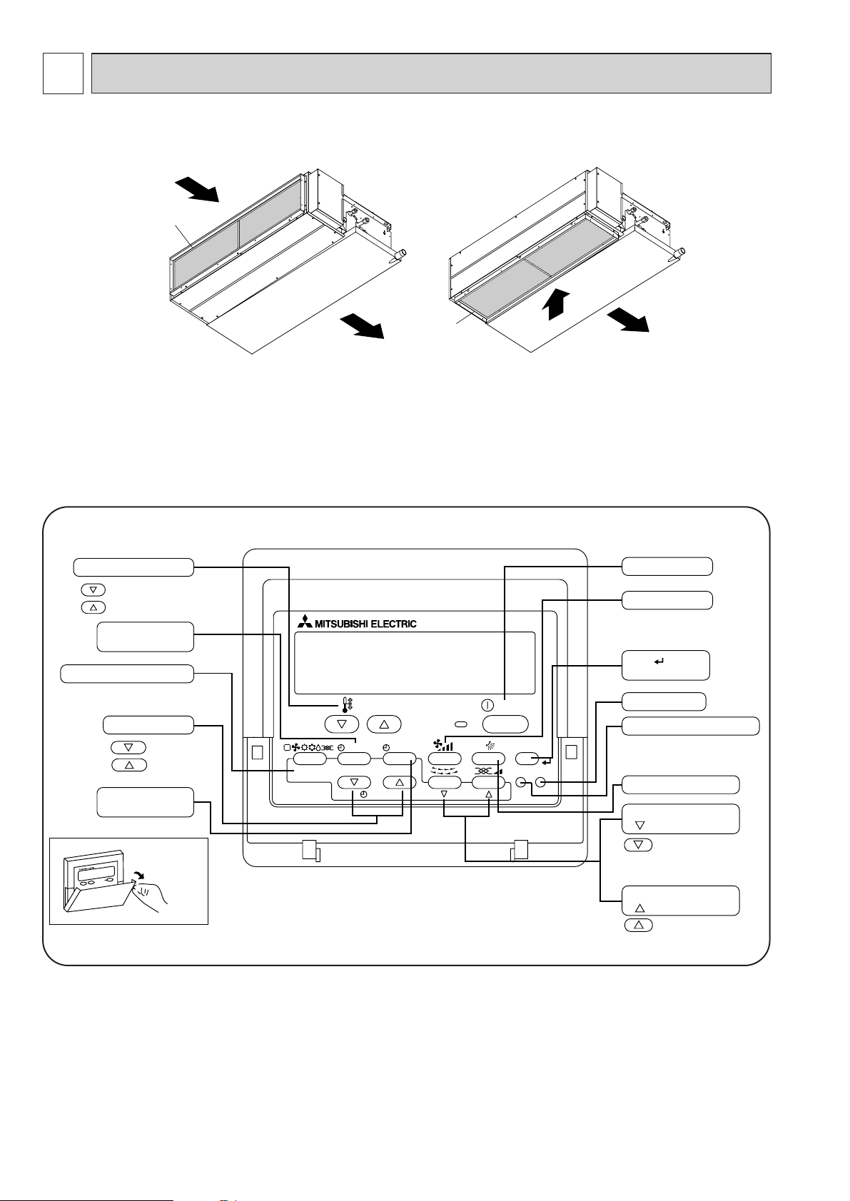
PART NAMES AND FUNCTIONS
● Indoor (Main) Unit
● Remote controller
Once the controls are set, the same operation mode can be repeated by simply pressing the ON/OFF button.
● Operation buttons
PAR-21MAA
ON/OFF
FILTER
CHECK
OPERATION
CLEAR
TEST
TEMP.
MENU
BACK DAY
MONITOR/SET
CLOCK
ON/OFF
Set Temperature buttons
Down
Up
Timer Menu button
(Monitor/Set button)
Mode button (Return button)
Set Time buttons
Back
Ahead
Timer On/Off button
(Set Day button)
Opening the
door.
ON/OFF button
Fan Speed button
Filter button
(<Enter> button)
Test Run button
Check button (Clear button)
Airflow Up/Down button
Louver button
(
Operation button)
To preceding operation
number.
Ventilation button
(
Operation button)
To next operation number.
In case of rear inlet
Air intake (sucks
the air inside the
room into the
unit)
Air outlet
In case of bottom inlet
(Only 1.6~2.5EAK(H))
A
A
Page 3
3
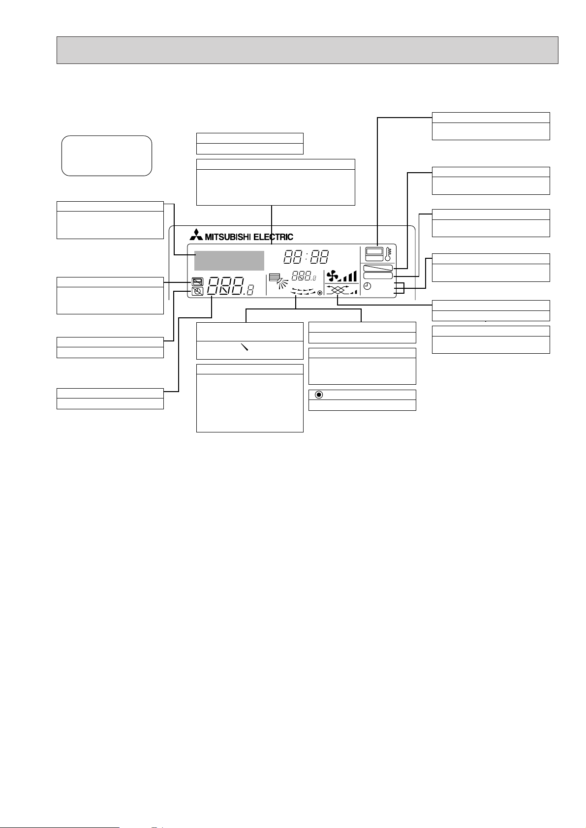
● Display
For purposes of this explanation,
all parts of the display are shown
as lit. During actual operation, only
the relevant items will be lit.
˚F˚C
˚F˚C
ERROR CODE
AFTER
TIMER
TIME SUN MON TUE WED THU FRI SAT
ON
OFF
Hr
AFTER
FILTER
FUNCTION
ONLY1Hr.
WEEKLY
SIMPLE
AUTO OFF
Identifies the current operation
Shows the operating mode, etc.
* Multilanguage display is sup-
ported.
“Centrally Controlled” indicator
Indicates that operation of the remote controller has been prohibited by a master controller.
“Timer Is Off” indicator
Indicates that the timer is off.
Temperature Setting
Shows the target temperature.
Day-of-Week
Shows the current day of the week.
Time/Timer Display
Shows the current time, unless the simple or Auto Off
timer is set.
If the simple or Auto Off timer is set, shows the time
remaining.
“Sensor” indication
Displayed when the remote controller
sensor is used.
“Locked” indicator
Indicates that remote controller buttons have been locked.
“Clean The Filter” indicator
Comes on when it is time to clean the
filter.
Timer indicators
The indicator comes on if the corresponding timer is set.
Up/Down Air Direction indicator
The indicator shows the direction of the outcoming airflow.
“One Hour Only” indicator
Displayed if the airflow is set to
weak and downward during COOL
or DRY mode. (Operation varies
according to model.)
The indicator goes off after one
hour, at which time the airflow direction also changes.
Room Temperature display
Shows the room temperature.
Louver display
Indicates the action of the swing
louver. Does not appear if the
louver is stationary.
(Power On indicator)
Indicates that the power is on.
Fan Speed indicator
Shows the selected fan speed.
Ventilation indicator
Appears when the unit is running in
Ventilation mode.
Caution
● Only the Power on indicator lights when the unit is stopped and power supplied to the unit.
● If you press a button for a feature that is not installed at the indoor unit, the remote controller will display the “Not Available”
message.
If you are using the remote controller to drive multiple indoor units, this message will appear only if he feature is not
present at the parent unit.
● When power is turned ON for the first time, it is normal that “PLEASE WAIT” is displayed on the room temperature indication
(For max. 2minutes). Please wait until this “PLEASE WAIT” indication disappear then start the operation.
Page 4
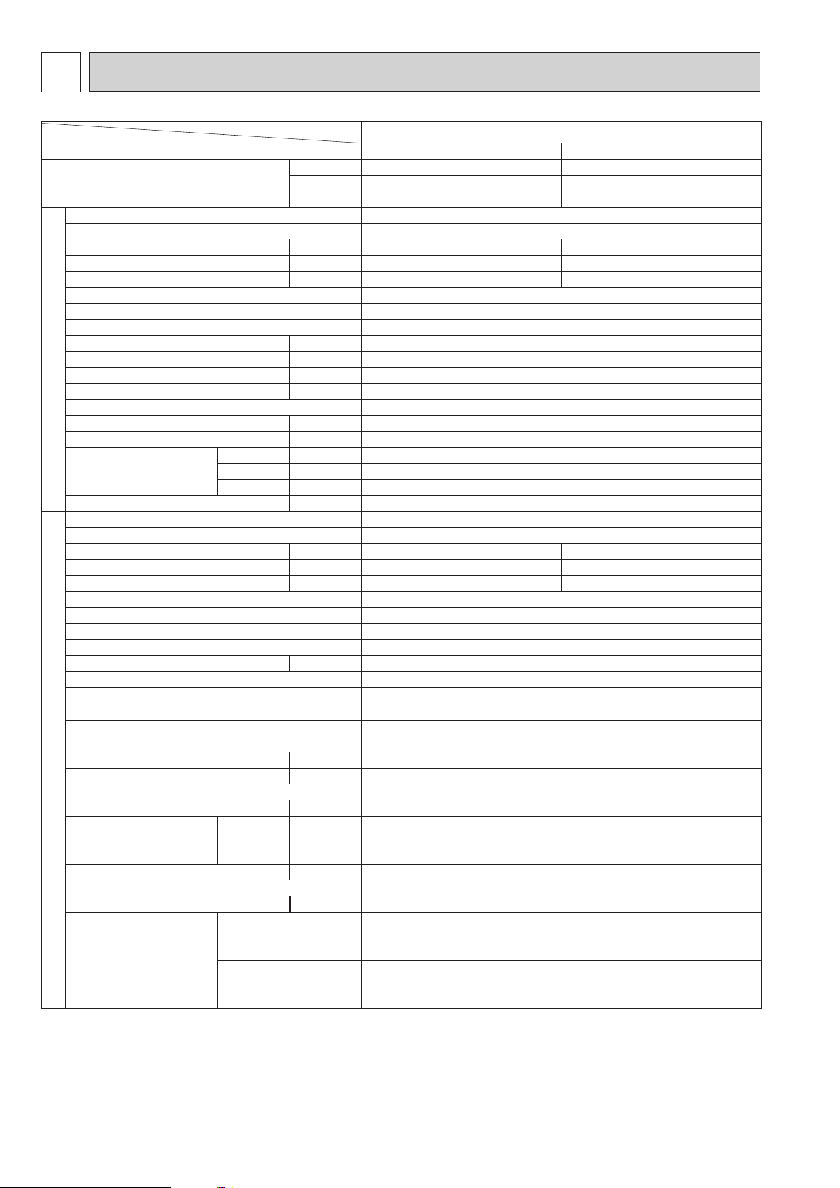
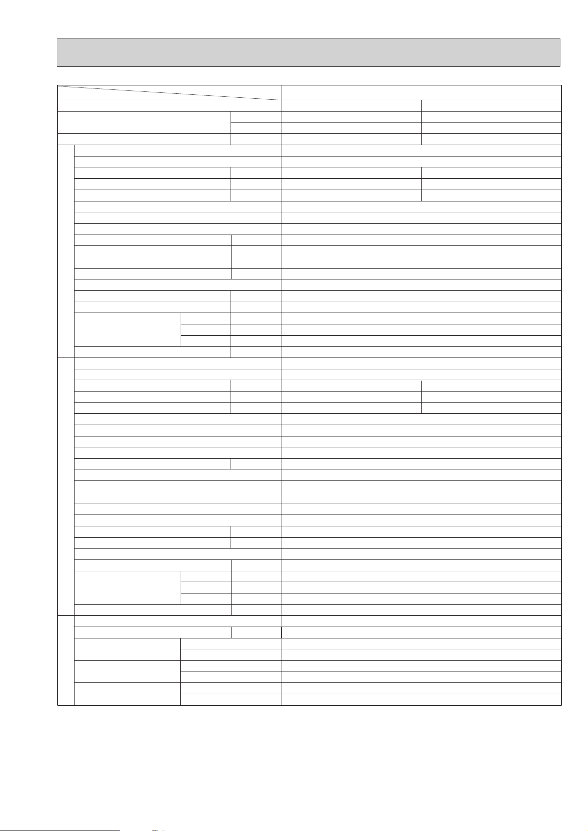
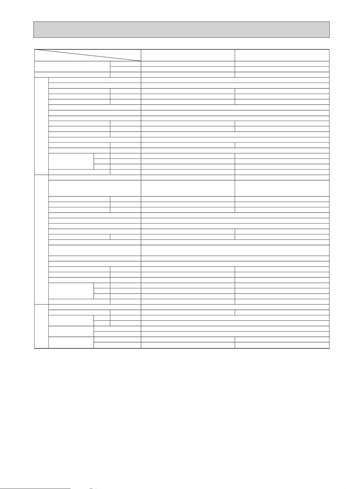
4
Item
Function
Capacity
Total input
INDOOR UNIT
Service Ref.
Power supply
Starting current
Running current
Input
External finish
Heat exchanger
Fan(drive) x No.
Fan motor output
Airflow(Low-High)
External static pressure
Booster heater
Operation control & Thermostat
Noise level(Low-High)
Cond.drain conn.O.D.
Dimensions
Weight
dB(A)
mm,(in)
mm,(in)
mm,(in)
mm,(in)
W
D
H
kg,(lbs)
Service Ref.
Power supply
Input
Running current
Starting current
External finish
Refrigerant control
Compressor
Model
Motor output
kW
Protection devices
Stater type
Heat exchanger
Fan(drive) x No.
Fan motor output
kW
Airflow
m3/min(CFM)
Defrost method
Noise level
dB(A)
Dimensions
W
D
H
mm,(in)
mm,(in)
mm,(in)
kg,(lbs)
Weight
Refrigerant
kg,(lbs)
Charge
Pipe size O.D.
Connection method
Between the indoor
& outdoor unit
Liquid mm,(in)
Gas mm,(in)
Indoor side
Outdoor side
Height difference
Piping length
REFRIGERANT
PIPING
OUTDOOR UNIT
kW
A
A
Btu/h
W
kW
kW
A
A
kW
kW
m3/min(CFM)
Pa(mmAq)
Service Ref.
4
4
✻✻
✻
✻
✻
✻
✻
✻
✻
✻
✻
5
1
2
3
1. External static pressure at 70Pa
2. Ex-works at 30Pa
3. External static pressure at 30Pa
4. Rating conditions <JIS B 8616>
(INDOOR) Cooling: 27˚CDB, 19˚CWB Heating: 20˚CDB
(OUTDOOR) Cooling: 35˚CDB Heating: 7˚CDB, 6˚CWB
5. Noise level: Sound pressure level
PEHD-1.6EAKH.UK
Cooling
15,000
4,400
1.57
PEHD-1.6EAKH.UK
~/N,50Hz, 220-240V
0.13
0.55
0.92
0.13 (1.13)
0.55 (4.71)
0.92 (5.08)
~/N, 220-240V ,50Hz
Galvanized sheets
Plate fin coil
Centrifugal (direct)x2
0.043
11-14 (388-494)
30(3)/70(7) at Hi-notch
1.0
Remote control & Built-in
34-38
32 (1-1/4)
935 (36-13/16)
700 (27-9/16)
295 (11-5/8)
35 (77)
PUH-1.6VKA.TH
1.44
6.74
33
1.41
6.60
33
Munsell 5Y7/1
Capillary tube
Hermetic
RH247VFCT
1.2
Line start
Plate fin coil
Propeller (direct)x1
0.065
45 (1590)
Reverse cycle
49
870 (34-1/4)
295+24 (11-5/8 add 1)
650 (25-5/8)
53 (117)
R-22
2.2 (4.8)
9.52 (3/8)
15.88 (5/8)
Flared
Flared
Max.40m
Max.40m
Heating
15,700 (19,100)
4,600 (5,600)
1.54 (2.54)
Inner thermostat,HP switch
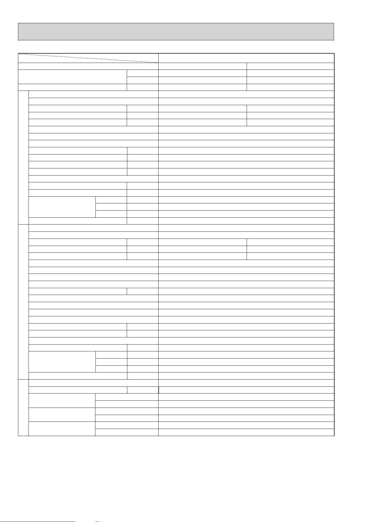
SPECIFICATIONS2
Page 5
5
Item
Function
Capacity
Total input
Service Ref.
Power supply
Input
Running current
Starting current
External finish
Heat exchanger
Fan(drive) x No.
Fan motor output
Airflow(Low-High)
External static pressure
Booster heater
INDOOR UNIT
Operation control & Thermostat
Noise level(Low-High)
Cond.drain conn.O.D.
Dimensions
Weight
Service Ref.
Power supply
Input
Running current
Starting current
External finish
Refrigerant control
Compressor
Model
Motor output
Stater type
Protection devices
Service Ref.
Btu/h
4
✻
4
✻
5
✻✻
W
D
H
W
kW
kW
A
A
kW
m3/min(CFM)
Pa(mmAq)
kW
dB(A)
mm,(in)
mm,(in)
mm,(in)
mm,(in)
kg,(lbs)
kW
A
A
kW
1
✻
2
✻
3
Cooling
19,100
5,600
2.35
0.15
0.63
1.1
2.20
9.86
45
PEHD-2EAKH.UK
Heating
21,500 (24,900)
6,300 (7,300)
2.37 (3.37)
PEHD-2EAKH.UK
~/N, 50Hz, 220-240V
0.15 (1.15)
0.63 (4.79)
1.1 (5.26)
Galvanized sheets
Plate fin coil
Centrifugal (direct)x2
0.076
13.5-17 (476-600)
30(3) / 70(7) at Hi-notch
1.0
Remote control & Built-in
36-40
32 (1-1/4)
935 (36-13/16)
700 (27-9/16)
295 (11-5/8)
35(77)
PUH-2VKA.TH
~/N, 220-240V, 50Hz
2.22
9.95
45
Munsell 5Y7/1
Capillary tube
Hermetic
NH38VMDT
1.7
Line start
Inner thermostat, HP switch
Heat exchanger
Fan(drive) x No.
OUTDOOR UNIT
Fan motor output
Airflow
Defrost method
Noise level
Dimensions
Weight
Refrigerant
Charge
Pipe size O.D.
PIPING
Connection method
REFRIGERANT
Between the indoor
& outdoor unit
1. External static pressure at 70Pa
✻
2. Ex-works at 30Pa
✻
✻
3. External static pressure at 30Pa
kW
m3/min(CFM)
dB(A)
W
D
H
Liquid mm,(in)
Gas mm,(in)
Indoor side
Outdoor side
Height difference
Piping length
mm,(in)
mm,(in)
mm,(in)
kg,(lbs)
kg,(lbs)
Plate fin coil
Propeller (direct) x1
0.065
45 (1590)
Reverse cycle
49
870 (34-1/4)
295+24 (11-5/8 and 1)
650 (25-5/8)
64 (141)
R-22
2.2 (4.8)
9.52 (3/8)
15.88 (5/8)
Flared
Flared
Max.40m
Max.40m
4. Rating conditions <JIS B 8616>
✻
(INDOOR) Cooling: 27˚CDB, 19˚CWB Heating: 20˚CDB
(OUTDOOR) Cooling: 35˚CDB Heating: 7˚CDB, 6˚CWB
5. Noise level: Sound pressure level
✻
Page 6
6
Item
Function
Capacity
Total input
INDOOR UNIT
Service Ref.
Power supply
Starting current
Running current
Input
External finish
Heat exchanger
Fan(drive) x No.
Fan motor output
Airflow(Low-High)
External static pressure
Booster heater
Operation control & Thermostat
Noise level(Low-High)
Cond.drain conn.O.D.
Dimensions
Weight
dB(A)
mm,(in)
mm,(in)
mm,(in)
mm,(in)
W
D
H
kg,(lbs)
Service Ref.
Power supply
Input
Running current
Starting current
External finish
Refrigerant control
Compressor
Model
Motor output
kW
Protection devices
Stater type
Heat exchanger
Fan(drive) x No.
Fan motor output
kW
Airflow
m3/min(CFM)
Defrost method
Noise level
dB(A)
Dimensions
W
D
H
mm,(in)
mm,(in)
mm,(in)
kg,(lbs)
Weight
Refrigerant
kg,(lbs)
Charge
Pipe size O.D.
Connection method
Between the indoor
& outdoor unit
Liquid mm,(in)
Gas mm,(in)
Indoor side
Outdoor side
Height difference
Piping length
REFRIGERANT
PIPING
OUTDOOR UNIT
kW
A
A
Btu/h
W
kW
kW
A
A
kW
kW
m3/min(CFM)
Pa(mmAq)
Service Ref.
4
4
5
1
2
3
1. External static pressure at 70Pa
2. Ex-works at 30Pa
3. External static pressure at 30Pa
4. Rating conditions < JIS B 8616>
(INDOOR) Cooling: 27˚CDB, 19˚CWB Heating: 20˚CDB
(OUTDOOR) Cooling: 35˚CDB Heating: 7˚CDB, 6˚CWB
5. Noise level: Sound pressure level
PEHD-2.5EAKH.UK
Cooling
23,200
6,800
2.63
Heating
PEHD-2.5EAKH.UK
~/N, 50Hz, 220-240V
0.17
0.72
1.6
0.17 (1.67)
0.72 (6.96)
1.6 (7.84)
~/N, 220-240V, 50Hz
Galvanized sheets
Plate fin coil
Centrifugal (direct)x2
0.116
17-21 (600-740)
30(3) /70(7) at Hi-notch
1.5
Remote control & Built-in
37-41
32 (1-1/4)
1,175 (46-1/8)
700 (27-9/16)
295 (11-5/8)
44(97)
PUH-2.5VKA.TH
2.46
10.68
52
2.23
9.78
52
Munsell 5Y7/1
Capillary tube
Hermetic
NH41VMDT
2
Line start
Plate fin coil
Propeller(direct)x1
0.085
50 (1764)
Reverse cycle
52
870 (34-1/4)
295+24 (11-5/8 add 1)
650 (25-5/8)
68 (150)
R-22
2.8 (6.2)
9.52 (3/8)
15.88 (5/8)
Flared
Flared
Max.50m
Max.50m
24,600 (29,700)
7,200 (8,700)
2.40 (3.90)
Internal thermostat, HP switch
✻
✻
✻
✻
✻
✻
✻
✻
✻
✻
✻
Page 7
7
Item
Function
Capacity
Total input
Service Ref.
Power supply
Input
Running current
Starting current
External finish
Heat exchanger
Fan(drive) x No.
Fan motor output
Airflow(Low-High)
External static pressure
Booster heater
INDOOR UNIT
Operation control & Thermostat
Noise level(Low-High)
Cond.drain conn.O.D.
Dimensions
Weight
Service Ref.
Power supply
Input
Running current
Starting current
External finish
Refrigerant control
Compressor
Model
Motor output
Stater type
Protection devices
Heat exchanger
Fan(drive) x No.
OUTDOOR UNIT
Fan motor output
Airflow
Defrost method
Noise level
Dimensions
Weight
Refrigerant
Charge
Pipe size O.D.
PIPING
Connection method
REFRIGERANT
Between the indoor
& outdoor unit
Service Ref.
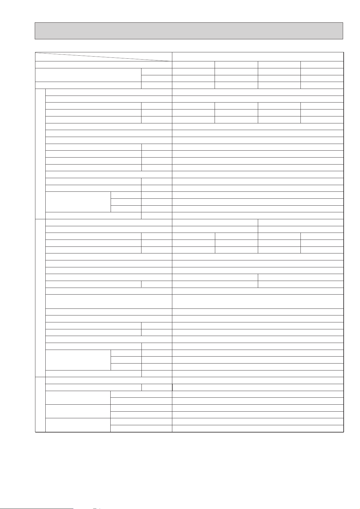
Cooling
✻
4
✻
5
✻✻
W
D
H
W
D
H
Liquid mm,(in)
Gas mm,(in)
Indoor side
Outdoor side
Height difference
Piping length
W
kW
kW
A
A
kW
m3/min(CFM)
Pa(mmAq)
kW
dB(A)
mm,(in)
mm,(in)
mm,(in)
mm,(in)
kg,(lbs)
kW
A
A
kW
kW
m3/min(CFM)
dB(A)
mm,(in)
mm,(in)
mm,(in)
kg,(lbs)
kg,(lbs)
Btu/h
4
28,300
8,300
3.55
0.40
1.70
1.90
1
✻
2
✻
3
3.15
13.82
58
V: Inner thermostat,HP switch
Y: Reversed-phase protector, Thermal relay, Thermal switch, HP switch
PEHD-3EAKH.UK
Heating
30,700 (37,900)
9,000 (11,100)
3.34 (5.44)
PEHD-3EAKH.UK
~/N,50Hz, 220-240V
0.40 (2.50)
1.70 (10.41)
1.90 (10.65)
Galvanized sheets
Plate fin coil
Centrifugal (direct)x2
0.15
20-25 (700-800)
70(7)/130(13) at Hi-notch
Remote control & Built-in
37-41
32 (1-1/4)
1,175 (46-1/8)
740 (29-1/8)
325 (12-13/16)
46 (101)
2.94
12.89
58
Munsell 5Y7/1
Capillary tube
Hermetic
NH52VNHT NH52YDAT
2.2 2.4
Line start
Plate fin coil
Propeller (direct)x2
0.085
50 (1764)
Reverse cycle
870 (34-1/4)
295+24 (11-5/8 add 1)
850 (33-7/16)
75 (165)
R-22
3.2 (7.1)
9.52 (3/8)
15.88 (5/8)
Flared
Flared
Max.50m
Max.50m
2.1
52
Cooling
28,300
8,300
3N~, 380/220-415/240V, 50Hz~/N, 220-240V ,50Hz
3.55
0.40
1.70
1.90
3.15
5.16
37
30,700 (37,900)
9,000 (11,100)
1.70 (10.41)
1.90 (10.65)
PUH-3YKA.THPUH-3VKA.TH
Heating
3.34 (5.44)
0.40 (2.50)
2.94
4.81
37
1. External static pressure at 130Pa
✻
2. Ex-works at 70Pa(OPTION MOTOR: 130Pa)
✻
✻
3. External static pressure at 70Pa
4. Rating conditions <JIS B 8616>
✻
(INDOOR) Cooling: 27˚CDB, 19˚CWB Heating: 20˚CDB
(OUTDOOR) Cooling: 35˚CDB Heating: 7˚CDB, 6˚CWB
5. Noise level: Sound pressure level
✻
Page 8
8
Item
Function
Capacity
Total input
INDOOR UNIT
Service Ref.
Power supply
Starting current
Running current
Input
External finish
Heat exchanger
Fan(drive) x No.
Fan motor output
Airflow(Low-High)
External static pressure
Booster heater
Operation control & Thermostat
Noise level(Low-High)
Cond.drain conn.O.D.
Dimensions
Weight
dB(A)
mm,(in)
mm,(in)
mm,(in)
mm,(in)
W
D
H
kg,(lbs)
Service Ref.
Power supply
Input
Running current
Starting current
External finish
Refrigerant control
Compressor
Model
Motor output
kW
Protection devices
Stater type
Heat exchanger
Fan(drive) x No.
Fan motor output
kW
Airflow
m3/min(CFM)
Defrost method
Noise level
dB(A)
Dimensions
W
D
H
mm,(in)
mm,(in)
mm,(in)
kg,(lbs)
Weight
Refrigerant
kg,(lbs)
Charge
Pipe size O.D.
Connection method
Between the indoor
& outdoor unit
Liquid mm,(in)
Gas mm,(in)
Indoor side
Outdoor side
Height difference
Piping length
REFRIGERANT
PIPING
OUTDOOR UNIT
kW
A
A
Btu/h
W
kW
kW
A
A
kW
kW
m3/min(CFM)
Pa(mmAq)
Service Ref.
4
4
✻✻
✻
✻
✻
✻
✻
✻
✻
✻
✻
5
1
2
3
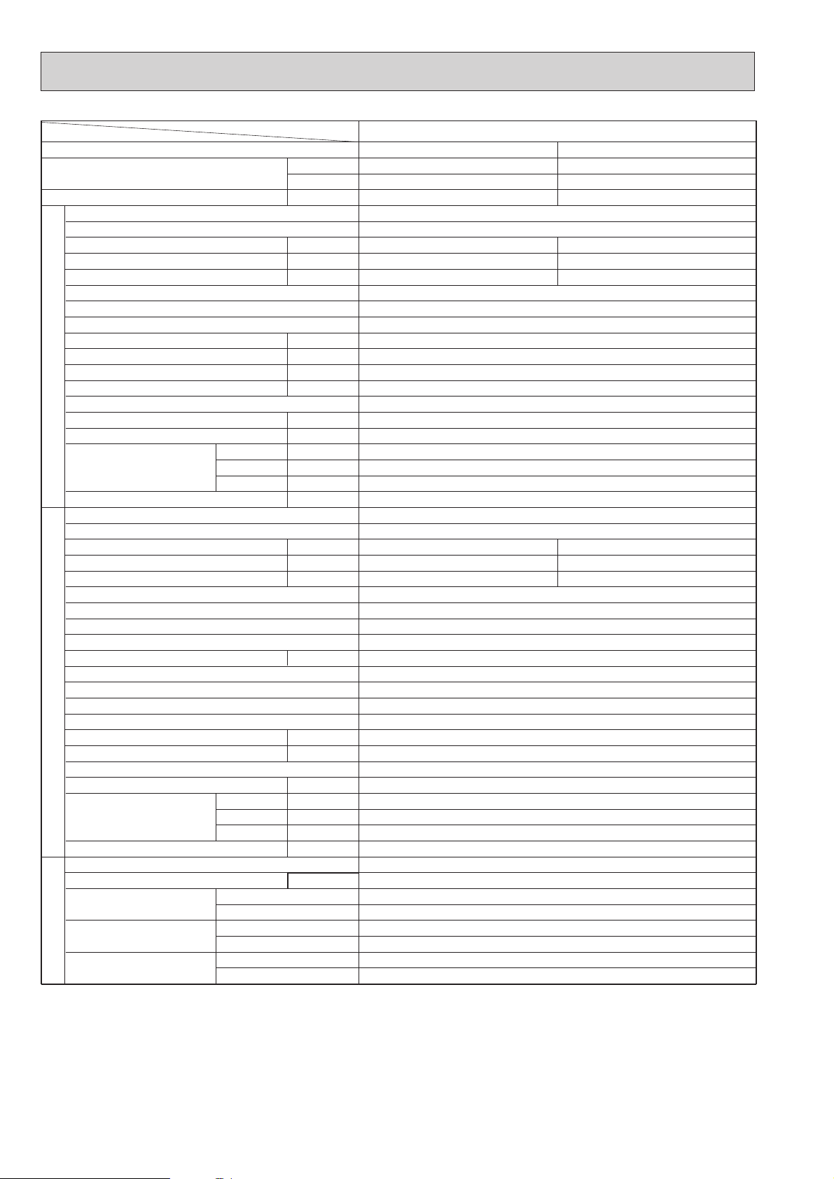
1. External static pressure at 130Pa
2. Ex-works at 70Pa(OPTION MOTOR: 130Pa)
3. External static pressure at 70Pa
4. Rating conditions <JIS B 8616>
(INDOOR) Cooling: 27˚CDB, 19˚CWB Heating: 20˚CDB
(OUTDOOR) Cooling: 35˚CDB Heating: 7˚CDB, 6˚CWB
5. Noise level: Sound pressure level
PEHD-4EAKH.UK
Cooling
33,100
9,700
3.82
Heating
PEHD-4EAKH.UK
~/N, 50Hz, 220-240V
0.62
2.64
3.20
0.62 (3.02)
2.64 (12.58)
3.20 (13.2)
3N~, 380/220-415/240V, 50Hz
Galvanized sheets
Plate fin coil
Centrifugal (direct)x2
0.27
27-34 (950-1200)
70(7) / 130(13) at Hi-notch
2.4
Remote control & Built-in
41-46
32 (1-1/4)
1,415 (55-11/16)
740 (29-1/8)
325 (12-13/16)
65(143)
PUH-4YKSA.TH
3.20
5.24
40
3.19
5.22
40
Munsell 5Y7/1
Capillary tube
Hermetic
NH56YDAT
2.7
Line start
Plate fin coil
Propeller (direct) x2
0.065+0.065
95 (3350)
Reverse cycle
54
870 (34-1/4)
295+24 (11-5/8 and 1)
1258 (49-1/2)
94 (207)
R-22
4.2 (9.2)
9.52 (3/8)
19.05 (3/4)
Flared
Flared
Max.50m
Max.50m
35,500 (43,700)
10,400 (12,800)
3.81 (6.21)
Reversed-phase protector, Thermal relay, Thermal switch, HP switch
Page 9
9
Item
Function
Capacity
Total input
Service Ref.
Power supply
Input
Running current
Starting current
External finish
Heat exchanger
Fan(drive) x No.
Fan motor output
Airflow(Low-High)
External static pressure
Booster heater
INDOOR UNIT
Operation control & Thermostat
Noise level(Low-High)
Cond.drain conn.O.D.
Dimensions
Weight
Service Ref.
Power supply
Input
Running current
Starting current
External finish
Refrigerant control
Compressor
Model
Motor output
Stater type
Protection devices
Heat exchanger
OUTDOOR UNIT
Fan(drive) x No.
Fan motor output
Airflow
Defrost method
Noise level
Dimensions
Weight
Refrigerant
Charge
Pipe size O.D.
PIPING
Connection method
REFRIGERANT
Between the indoor
& outdoor unit
Service Ref.
Btu/h
4
✽
4
✽
5
✽
W
D
H
W
D
H
Liquid mm,(in)
Gas mm,(in)
Indoor side
Outdoor side
Height difference
Piping length
W
kW
kW
A
A
kW
m3/min(CFM)
Pa(mmAq)
kW
dB(A)
mm,(in)
mm,(in)
mm,(in)
mm,(in)
kg,(lbs)
kW
A
A
kW
kW
m3/min(CFM)
dB(A)
mm,(in)
mm,(in)
mm,(in)
kg,(lbs)
kg,(lbs)
PEHD-5EAKH.UK
Cooling
42,300
12,400
4.85
PEHD-5EAKH.UK
~/N, 50Hz, 220-240V
0.64
2.72
6.00
Galvanized sheets
Plate fin coil
Centrifugal (direct)x2
1
✽
33.5-42 (1180-1480)
2
✽
3
✽
4.21
6.89
53
Internal thermostat, Anti-phase protector, Thermal relay,
70(7) /130(13) at Hi-notch
Remote control & Built-in
3N~, 380/220-415/240V, 50Hz
Thermal switch, HP switch
345+24 (13-9/16 add 1)
0.30
3.0
44-50
32 (1-1/4)
1,415 (55-11/16)
740 (29-1/8)
325 (12-13/16)
68(150)
PUH-5YKSA.TH
Munsell 5Y7/1
Capillary tube
Hermetic
ZR-61KC-TFD
3.5
Line start
Plate fin coil
Propeller(direct)x2
0.085+0.085
95 (3350)
Reverse cycle
55
970 (38-3/16)
1258 (49-1/2)
114 (251)
R-22
5.4 (11.9)
9.52 (3/8)
19.05 (3/4)
Flared
Flared
Max.50m
Max.50m
Heating
47,400 (57,700)
13,900 (16,900)
4.80 (7.80)
0.64 (3.64)
2.72 (15.17)
6.00 (18.50)
4.16
6.81
53
1. External static pressure at 130Pa
✽
2. Ex-works at 70Pa(OPTION MOTOR: 130Pa)
✽
3. External static pressure at 70Pa
✽
4. Rating conditions < JIS B 8616 >
✽
(INDOOR) Cooling: 27˚CDB, 19˚CWB Heating: 20˚CDB
(OUTDOOR) Cooling: 35˚CDB Heating: 7˚CDB, 6˚CWB
✽
5. Noise level: Sound pressure level
Page 10
10
PEHD-6EAKH.UK
Cooling
50,000
14,650
5.39
Heating
54,500 (64,700)
16,000 (19,000)
5.24 (8.24)
PEHD-6EAKH.UK
~ /N,50Hz,220-240V
0.66
2.79
6.25
0.66 (3.66)
2.79 (15.24)
6.25 (18.75)
3N~ , 380/220-415/240V, 50Hz
Galvanized sheets
Plate fin coil
Centrifugal (direct) x 2
0.30
36.5-46 (1,280-1,620)
70(7) / 130(13) at Hi-notch
3.0
Remote control & Built-in
46-51
32 (1-1/4)
1,715 (67-1/2)
740 (29-1/8)
325 (12-13/16)
73(161)
PUH-6YKSA.TH
4.73
7.74
74
4.58
7.50
74
Munsell 5Y7/1
Capillary tube
Hermetic
ZR68KC-TFD
4.0
Line start
Internal thermostat, Anti-phase protector, Thermal relay,
Thermal switch, HP switch
Plate fin coil
Propeller(direct)x 2
0.10+ 0.10
100 (3530)
Reverse cycle
56
970 (38-3/16)
345+ 24 (13-9/16 and 1)
1,258 (49-1/2)
117 (258)
R-22
5.0 (11.0)
9.52 (3/8)
19.05 (3/4)
Flared
Flared
Max.50m
Max.50m
Item
Function
Capacity
Total input
INDOOR UNIT
Service Ref.
Power supply
Starting current
Running current
Input
External finish
Heat exchanger
Fan(drive) x No.
Fan motor output
Airflow(Low-High)
External static pressure
Booster heater
Operation control & Thermostat
Noise level(Low-High)
Cond.drain conn.O.D.
Dimensions
Weight
dB(A)
mm,(in)
mm,(in)
mm,(in)
mm,(in)
W
D
H
kg,(lbs)
Service Ref.
Power supply
Input
Running current
Starting current
External finish
Refrigerant control
Compressor
Model
Motor output
kW
Protection devices
Stater type
Heat exchanger
Fan(drive) x No.
Fan motor output
kW
Airflow
m3/min(CFM)
Defrost method
Noise level
dB(A)
Dimensions
W
D
H
mm,(in)
mm,(in)
mm,(in)
kg,(lbs)
Weight
Refrigerant
kg,(lbs)
Charge
Pipe size O.D.
Connection method
Between the indoor
& outdoor unit
Liquid mm,(in)
Gas mm,(in)
Indoor side
Outdoor side
Height difference
Piping length
REFRIGERANT
PIPING
OUTDOOR UNIT
kW
A
A
Btu/h
W
kW
kW
A
A
kW
kW
m3/min(CFM)
Pa(mmAq)
Service Ref.
✽ 4
✽ 4
✽ 5
✽ 1
✽ 2
✽ 3
✽ 1. External static pressure at 130Pa
✽ 2. Ex-works at 70Pa(OPTION MOTOR: 130Pa)
✽ 3. External static pressure at 70Pa
✽ 4. Rating conditions < JIS B 8616 >
(INDOOR) Cooling: 27˚CDB, 19˚CWB Heating: 20˚CDB
(OUTDOOR) Cooling: 35˚CDB Heating: 7˚CDB, 6˚CWB
✽ 5. Noise level: Sound pressure level
Page 11
11
Item
Cooling capacity
Total input 4 kW 2.69
Service Ref.
Power
supply
Input kW 0.17
Running current A 0.72
Starting current A 1.6
External finish
Heat exchanger
Fan (drive) ~No.
Fan motor output 1 kW 0.116
Airflow (Low-High)
External static pressure 2 Pa(mmAq)
Operation control & Thermostat
INDOOR UNIT
Noise level (Low-High)
Cond. drain conn. O.D.
Dimensions
Weight
Service Ref.
Power supply
Input kW
Running current A
Starting current A
External finish
Refrigerant control
Compressor
UNIT
Model
Motor output kW
Starter type
Protection devices Inner thermostat,HP switch,LP switch
OUTDOOR
Heat exchanger
Fan (drive) ~No.
Fan motor output kW 0.085
Airflow
Noise level dB (A) 52
Dimensions D mm, (in)
Weight kg, (lbs) 71(157)
Refrigerant
Charge kg, (lbs) 2.4(5.29)
Pipe size O.D. Liquid mm, (in)
Connection method Indoor side
PIPING
Between the indoor Height difference
REFRIGERANT
& outdoor unit Piping length
✻
Gas mm, (in)
Outdoor side
Service Ref.
4 Btu/h 22,900
✻
W 6,700
✻
✻
m3/min(CFM)
✻
3, 5 dB (A) 37-41
✻
W mm, (in) 1175(46-1/8)
W mm, (in) 870(34-1/4)
mm, (in)
D mm, (in) 700(27-9/16)
H mm, (in) 295(11-5/8)
kg, (lbs) 42(93)
m3/min,(CFM) 50(1765)
H mm, (in) 850(33-7/16)
(m)
(m)
18,800
5,500
2.63
0.15
0.63
1.1
0.076
13.5- 17(476-600)
36-40
935(36-13/16)
700(27-9/16)
295(11-5/8)
33(73)
PU-2VJA
Propeller(direct)X1
295+24(11-5/8 add 1) 295+24(11-5/8 add 1)
1.TH PU-2.5VJA1.TH
~/N
50Hz
220-240V
2.48
10.8
52
0.065
45(1588)
49
870(34-1/4)
650(25-5/8)
60(132)
1.78(3.92)
~/N, 50Hz, 220-240V
Galvanized sheets
Plate fin coil
Centrifugal (direct)x2
30(3)/70(7) at Hi-notch
Remote control&Built-in
32(1-1/4)
Munsell 5Y 7/1
Capillary tube
Hermetic
NHJ41VMDT
2.0
Line Start
Plate fin coil
R-22
9.52(3/8)
15.88(5/8)
Flared
Flared
30
30
PED-2.5EAK.UKPED-2EAK.UK
PED-2.5EAK.UKPED-2EAK.UK
17-21 (600-740)
~/N
50Hz
220-240V
2.52
10.7
52
Propeller(direct)X1
1. External static pressure at 70Pa. 4.Rating condition <JIS B 8616>
✻✻
2. Ex-works at 30Pa. INDOOR : 27 ˚CDB, 19 ˚CWB
✻
3. External static pressure at 30Pa. OUTDOOR : 35 ˚CDB
✻
5.Noise level : Sound pressure level
✻
Page 12
12
Service Ref.
PED-4EAK.UKPED-3EAK.UK
PED-4EAK.UKPED-3EAK.UK
Item
Cooling capacity
4 Btu/h 33,100
W 9,700
Total input 4 kW 3.98
Power
Service Ref.
supply
~(1ph),50Hz,220-240V
Input kW 0.62
Running current A 2.64
Starting current A 3.2
External finish
Galvanized sheets
Heat exchanger
Plate fin coil
Plate fin coil
Fan (drive) ~No.
Centrifugal (direct)x2
Fan motor output 1 kW 0.27
Airflow (Low-High)
m3/min(CFM)
27- 34(950-1200)
External static pressure 2 Pa(mmAq)
70(7)/130(13) at Hi-notch
Operation control & Thermostat
Remote control&Built-in
Noise level (Low-High)
3, 5 dB (A) 41-46
Cond. drain conn. O.D.
mm, (in)
32(1-1/4)
W mm, (in) 1415(55-11/16)
Dimensions
D mm, (in) 740(29-1/8)
H mm, (in) 325(12-13/16)
Weight
kg, (lbs) 62(137)
Service Ref.
Power supply
Input kW 3.36
Running current A 5.5
Starting current A 38
3.52
16.3
79
External finish
Munsell 5Y 7/1
Refrigerant control
Capillary tube
Compressor
Hermetic
Model NHJ56YDAT
Motor output kW 2.7
Starter type
Line Start
Protection devices
V(L) : Inner thermostat,HP switch,LP switch
Y : Reversed-phase protector,Thermal switch,Thermal relay,HP switch,LP switch
Heat exchanger
Fan (drive) ~No.
Fan motor output kW 0.065+0.065
Airflow
m3/min(CFM) 95(3352)
Noise level dB (A) 54
W mm, (in) 870(34-1/4)
Dimensions D mm, (in)
H mm, (in) 1258(49-1/2)
Weight kg, (lbs) 94(207)
Refrigerant
R-22
Charge kg, (lbs) 4.6(10.14)
NH56VNHT
2.7
3.8(8.38)
Pipe size O.D. Liquid mm, (in)
9.52(3/8)
Gas mm, (in)
(m)
(m)
19.05(3/4)
Connection method Indoor side
Flared
Outdoor side
Flared
Between the indoor Height difference 30
& outdoor unit Piping length 40
27,000
7,900
3.60
0.4
1.70
1.9
0.15
20- 25(700-800)
37-41
1175(46-1/8)
740(29-1/8)
325(12-13/16)
44(108)
PU-3YJC.THPU-3VJC
1.TH PU-4YJSA1.THPU-4VLJSA2.TH
3N~(3ph,4wires)
50Hz
380-415V
~(1ph)
50Hz
220-240V
3.20
5.3
37
3.20
13.9
58
3N~(3ph,4wires)
50Hz
380-415V
~(1ph)
50Hz
220-240V
NH52YDAT
2.4
NH52VNHT
2.2
Propeller(direct)X1
Propeller(direct)X2
0.085
50(1765)
52
870(34-1/4)
295+24(11-5/8 add 1) 295+24(11-5/8 add 1)
850(33-7/16)
73(161)
2.8(6.2)2.8(6.2)
15.88(5/8)
20
30
1. External static pressure at 130Pa. 4.Rating condition <JIS B 8616>
2. Ex-works at 70Pa(OPTION MOTOR :130Pa) INDOOR : 27 ˚CDB, 19 ˚CWB
3. External static pressure at 70Pa. OUTDOOR : 35 ˚CDB
5.Noise level : Sound pressure level
INDOOR UNIT
OUTDOOR
UNIT
REFRIGERANT
PIPING
✻
✻
✻
✻✻
✻
✻
✻
✻
✻
✻
Page 13
13
Item
Cooling capacity
Total input 4 kW 5.84
Service Ref.
Power supply
Input kW 0.66
Running current A 2.79
Starting current A 6.25
External finish
Heat exchanger
Fan (drive) ~No.
Fan motor output 1 kW 0.30
Airflow (Low-High)
External static pressure 2 Pa(mmAq)
Operation control & Thermostat
INDOOR UNIT
Noise level (Low-High)
Cond. drain conn. O.D.
Dimensions
Weight
Service Ref.
Power supply
Input kW 5.18
Running current A 8.48
Starting current A 74
External finish
Refrigerant control
Compressor
Model ZR72KCTFD
Motor output kW 4.2
Starter type
Protection devices
OUTDOOR UNIT
Heat exchanger
Fan (drive) ~No.
Fan moter output kW 0.10+0.10
Airflow
Noise level dB (A) 56
Dimensions D mm, (in)
Weight kg, (lbs) 117(258)
Refrigerant
Charge kg, (lbs) 5.7(12.57)
Pipe size O.D. Liquid mm, (in)
Connection method Indoor side
PIPING
Between the indoor Height difference 50
REFRIGERANT
& outdoor unit Piping length 50
✻
✻
✻
3, 5 dB (A) 46-51
✻
Gas mm, (in)
Outdoor side
Service Ref.
4 Btu/h 50,400
W 14,800
m3/min(CFM)
✻
✻
mm, (in)
W mm, (in) 1715(67-1/2)
D mm, (in) 740(29-1/8)
H mm, (in) 325(12-13/16)
kg, (lbs) 70(154)
Y : Reversed-phase protector,Thermal switch,Thermal relay,HP switch,LP switch
m3/min(CFM) 100(3530)
W mm, (in) 970
H mm, (in) 1258(49-1/2)
(m)
(m)
42,300
12,400
5.3
0.64
2.72
6.0
0.40
33.5- 42(1180-1480)
44-50
1415(55-11/16)
740(29-1/8)
325(12-13/16)
65(143)
PU-5YJSA
3N~(3ph,4wires)
ZR61KCTFD
345+24(13-9/16 add 1) 345+24(13-9/16 add 1)
1.TH PU-6YJSA1.TH
50Hz
380-415V
4.66
7.63
65.5
3.5
0.10+0.10
100(3530)
55
970
1258(49-1/2)
114(251)
5.1(11.24)
50
50
~(1ph),50Hz,220-240V
Galvanized sheets
Plate fin coil
Centrifugal (direct)x2
70(7)/130(13) at Hi-notch
Remote control&Built-in
32(1-1/4)
Munsell 5Y 7/1
Capillary tube
Hermetic
Line Start
Plate fin coil
Propeller(direct)X2
R-22
9.52(3/8)
19.05(3/4)
Flared
Flared
PED-6EAK.UKPED-5EAK.UK
PED-6EAK.UKPED-5EAK.UK
36.5- 46(1280-1620)
3N~(3ph,4wires)
50Hz
380-415V
1. External static pressure at 130Pa. 4.Rating condition < JIS B 8616
✻
2. Ex-works at 70Pa(OPTION MOTOR :130Pa) INDOOR : 27˚C DB, 19˚C WB
✻
✻
3. External static pressure at 70Pa. OUTDOOR : 35˚C DB
✻
5.Noise level : Sound pressure level
✻
>
Page 14
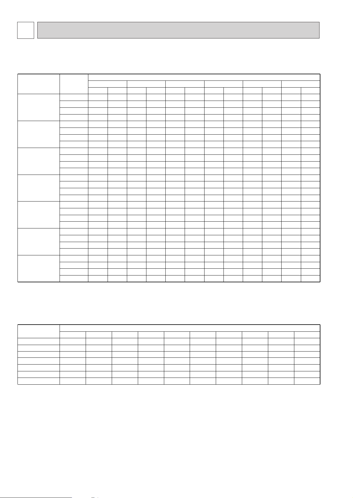
Service Ref.
Indoor
intake air
WB˚C
20 25 30 35 40 45
CA P.C. CA P.C. CA P.C. CA P.C. CA P.C. CA P.C.
1) COOLING CAPACITY
Note C A: Capacity(W)
P.C.: Power consumption(kW)
Service Ref.
Refrigerant piping length(one way)
5m 10m 15m 20m 25m 30m 35m 40m 45m 50m
Cooling capacity correction factors
Outdoor intake air DB˚C
PEHD-1.6EAKH.UK
PEHD-2EAKH.UK
PEHD-2.5EAKH.UK
PEHD-3EAKH.UK
PEHD-4EAKH.UK
PEHD-5EAKH.UK
PEHD-6EAKH.UK
PEHD-3EAKH.UK
PEHD-4EAKH.UK
PEHD-5EAKH.UK
PEHD-6EAKH.UK
4,479 1.27
1.30
1.32
1.34
1.90
1.95
1.97
2.01
2.13
2.17
2.20
2.24
4,356
4,642
4,937
5,249
5,544
5,909
6,283
6,681
6,732
7,175
7,630
8,112
8,217
8,757
9,312
9,902
1.33
1.35
1.37
1.40
1.99
2.02
2.06
2.10
2.22
2.26
2.30
2.35
4,180
4,453
4,743
5,047
5,320
5,667
6,037
6,423
6,460
6,882
7,330
7,800
7,885
8,399
8,948
9,520
1.42
1.46
1.49
1.51
2.12
2.17
2.22
2.27
2.37
2.43
2.48
2.53
3,991
4,259
4,541
4,840
5,079
5,421
5,779
6,160
6,168
6,582
7,018
7,480
7,528
8,035
8,565
9,130
1.51
1.55
1.59
1.63
2.27
2.32
2.38
2.44
2.53
2.60
2.66
2.72
3,793
4,057
4,334
4,629
4,827
5,163
5,516
5,891
5,862
6,270
6,698
7,154
7,154
7,652
8,176
8,731
1.61
1.65
1.69
1.74
2.41
2.47
2.53
2.61
2.69
2.76
2.84
2.91
3,590
3,850
4,123
4,409
4,570
4,901
5,247
5,611
5,549
5,951
6,372
6,814
6,773
7,263
7,777
8,316
1.28
1.37
1.48
1.57
1.92
2.06
2.20
2.36
2.14
2.30
2.46
2.63
16
4,76518
5,05620
5,35022
5,70116
6,06518
6,43420
6,81022
6,92216
7,36418
7,81320
8,269
8,450
8,989
9,536
10,093
22
16
18
20
22
16
18
20
22
16
18
20
22
16
18
20
22
PEHD-1.6EAKH.UK
PEHD-2EAKH.UK
PEHD-2.5EAKH.UK
1.00 0.993
0.992
0.989
0.984
0.983
0.980
0.978
0.978
0.970
0.969
0.966
0.960
0.961
0.959
0.950
0.956
0.950
0.940
0.948
0.945
0.930
-
-
0.920
-
-
0.910
1.00
1.00
2.87 3.00 3.21 3.43 3.64 2.90
2.94 3.06 3.29 3.51 3.74 3.10
2.98 3.11
9,215
3.35 3.60 3.83 3.33
3.04 3.18 3.43 3.68 3.94 3.56
9,875 3.09 9,603 3.23 3.46 8,798 3.69 8,361 3.92 7,915 3.11
10,505 3.16 10,234 3.29 9,816 3.54 9,390 3.78 8,943 4.02 8,488 3.34
11,145 3.20 10,883 3.34 10,457 3.61 10,010 3.87 9,555 4.12 9,089 3.58
11,795 3.26 11,572 3.41 11,126 3.69 10,670 3.96 10,204 4.24 9,719 3.83
12,623 3.92 12,276 4.10 11,780 4.39 11,247 4.68 10,689 4.98 10,118 3.96
13,429 4.01 13,083 4.18 12,549 4.49 12,003 4.80 11,433 5.11 10,851 4.25
14,247 4.07 13,913 4.25 13,367 4.58 12,797 4.91 12,215 5.24 11,619 4.54
15,078 4.15 14,793 4.34 14,223 4.68 13,640 5.03 13,045 5.38 12,425 4.86
1.00 0.981 0.968 0.952 0.940 0.925 0.913 0.900 0.886 0.874
1.00 0.989 0.980 0.970 0.960 0.950 0.940 0.930 0.920 0.910
1.00 0.981 0.968 0.952 0.940 0.925 0.913 0.900 0.886 0.874
14,782
15,734
16,701
17,683
4.32 14,372 4.50 13,844 4.86 13,273 5.20 12,731 5.55 12,116 5.90
4.40 15,324 4.60 14,767 4.96 14,177 5.33 13,581 5.69 12,951 6.05
4.49 16,305 4.68 15,734 5.07 15,119 5.45 14,489 5.84 13,844 6.24
4.58 17,346 4.78 16,745 5.17 16,115 5.58 15,456 6.00 14,782 6.44
1.00 0.975 0.955 0.935 0.918 0.900 0.884 0.869 0.855 0.840
14
3
DATA
1. PERFORMANCE DATA
Page 15
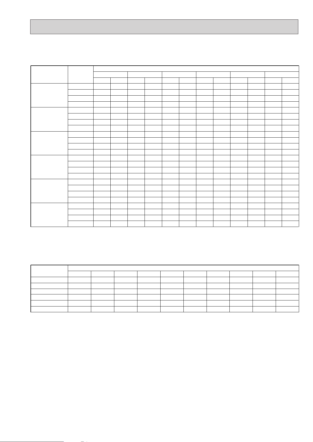
15
2) COOLING CAPACITY
Service Ref.
PED-2EAK.UK
PED-2.5EAK.UK
PED-3EAK.UK
PED-4EAK.UK
PED-5EAK.UK
PED-6EAK.UK
Indoor
intake air
WB˚C
16
18
20
22
16
18
20
22
16
18
20
22
16
18
20
22
16
18
20
22
16
18
20
22
Note C A: Capacity(W)
P.C.: Power consumption(kW)
Outdoor intake air DB˚C
20 25 30 35 40 45
CA P.C. CA P.C. CA P.C. CA P.C. CA P.C. CA P.C.
5,599
5,957
6,320
6,688
6,821
7,256
7,698
8,147
8,042
8,556
9,077
9,606
9,875 3.22 9,603 3.36 9,215 3.60 8,798 3.84 8,361
10,505 3.29 10,234 3.43 9,816 3.69 9,390 3.93 8,943 4.19 8,488 3.48
11,145 3.34 10,883 3.48 10,457 3.76 10,010 4.04 9,555 4.29 9,089 3.73
11,795 3.40 11,572 3.56 11,126 3.84 10,670 4.13 10,204 4.42 9,719 3.99
12,623 4.29 12,276 4.48 11,780 4.79 11,247 5.12 10,689
13,429 4.38 13,083 4.57 12,549 4.91 12,003 5.25 11,433 5.58 10,851 4.64
14,247 4.45 13,913 4.64 13,367 5.01 12,797 5.36 12,215 5.72 11,619 4.97
15,078 4.53 14,793 4.74 14,223 5.12 13,640 5.49 13,045 5.88 12,425 5.31
15,066 14,652 14,060 13,424 12,758 12,076
16,028 15,615 14,978 14,326 13,646 12,951
17,004 16,606 15,954 15,274 14,579 13,868
17,996 17,656 16,976 16,280 15,570 1,4830
2.13
2.17
2.21
2.25
2.18
2.22
2.26
2.30
2.91 3.04 3.26 3.48
2.98 3.10 3.34 3.56 3.79 3.15
3.02 3.16 3.40 3.65 3.88 3.37
3.08 3.22 3.48 3.73 4.00 3.61
4.73 4.94 5.28 5.64
4.83 5.04 5.41 5.78 6.15 6.54
4.90 5.11 5.52 5.91 6.30 6.77
4.99 5.22 5.64 6.05 6.48 7.01
5,445
5,803
6,171
6,562
6,633
7,069
7,581
7,993
7,821
8,335
8,864
9,425
2.22
2.27
2.30
2.35
2.27
2.32
2.36
2.40
5,225
5,566
5,929
6,309
6,365
6,780
7,223
7,685
7,505
7,995
8,516
9,061
2.38
2.44
2.49
2.54
2.43
2.49
2.54
2.60
4,989
5,324
5,676
6,050
6,077
6,486
6,914
7,370
7,165
7,647
8,153
8,690
2.54
2.61
2.66
2.72
2.60
2.66
2.72
2.79
4,741
5,071
5,418
5,786
5,775
6,177
6,600
7,048
6,810
7,284
7,782
8,311
2.70
2.77
2.84
2.92
2.76
2.83
2.90
2.98
3.69
4.08
5.44
5.99
4,488
4,813
5,154
5,511
5,467
5,863
6,278
6,713
6,446
6,913
7,402
7,916
7,915 3.24
10,118 4.33
2.15
2.30
2.47
2.63
2.20
2.36
2.52
2.70
2.94
6.42
Cooling capacity correction factors
Service Ref.
PED-2EAK.UK
PED-2.5EAK.UK
PED-3EAK.UK
PED-4EAK.UK
PED-5EAK.UK
PED-6EAK.UK
5m 10m 15m 20m 25m 30m 35m 40m 45m 50m
1.00 0.985 0.975 0.964 0.954 0.944
1.00 0.983 0.972 0.961 0.951 0.940
1.00 0.978 0.962 0.948 0.934 0.921 - - - -
1.00 0.984 0.974 0.964 0.954 0.944 0.935 0.926 - -
1.00 0.978 0.962 0.948 0.934 0.921 0.908 0.896 0.884 -
1.00 0.970 0.950 0.931 0.912 0.896 0.880 0.864 0.850 0.840
Refrigerant piping length(one way)
----
----
Page 16
16
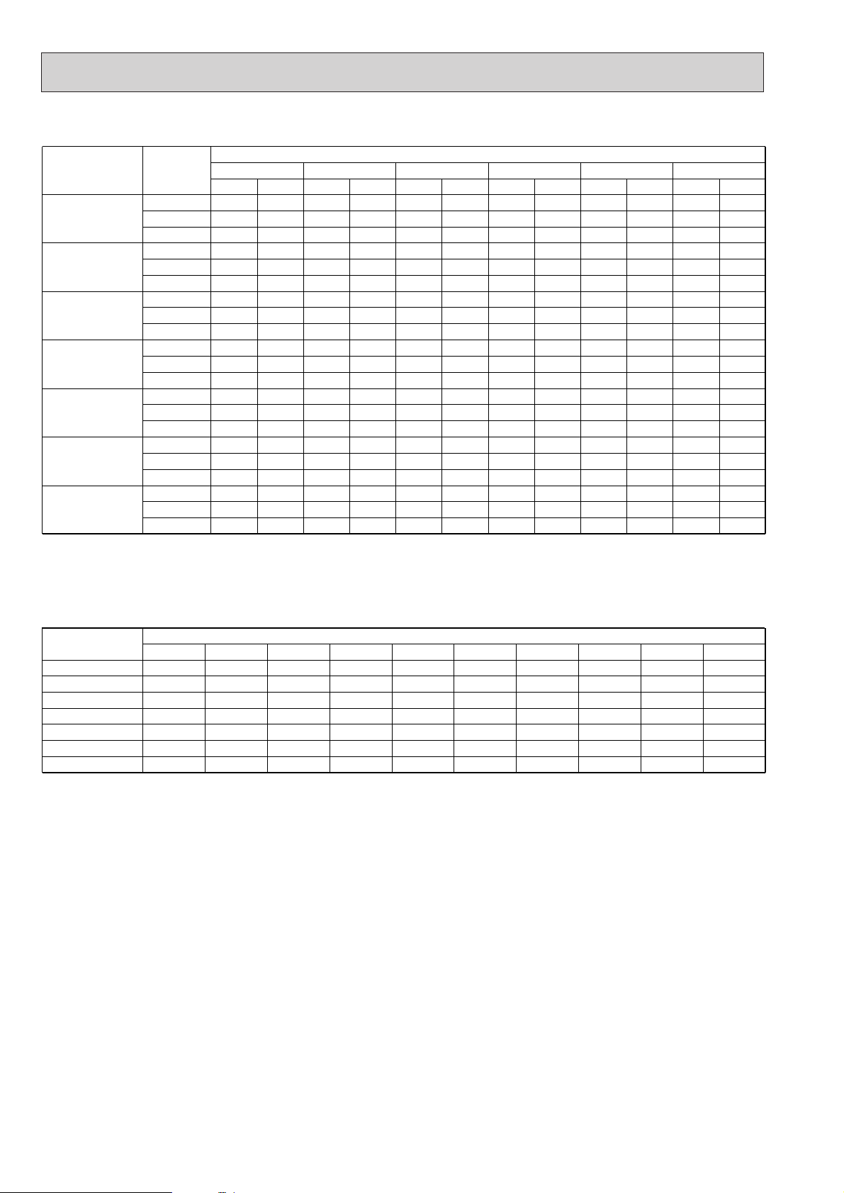
Service Ref. -10 -5 0 5 10 15
3) HEATING CAPACITY
Indoor
intake air
WB˚C
Outdoor intake air DB˚C
CA P.C. CA P.C. CA P.C. CA P.C. CA P.C. CA P.C.
Note C A : Capacity(W)
P.C.: Power consumption(kW)
Service Ref.
Refrigerant piping length(one way)
5m 10m 15m 20m 25m 30m 35m 40m 45m 50m
Heating capacity correction factors
PEHD-1.6EAKH.UK
PEHD-2EAKH.UK
PEHD-3EAKH.UK
PEHD-4EAKH.UK
PEHD-5EAKH.UK
PEHD-6EAKH.UK
PEHD-2.5EAKH.UK
3,192
3,054
2,940
4,372
4,183
4,026
4,996
4,780
4,601
1.05
2.05
1.20
1.61
1.73
1.85
1.63
1.76
1.87
2.27
2.44
2.60
3,643
3,500
3,358
4,990
4,794
4,599
5,703
5,479
5,256
1.15
1.24
1.32
1.77
1.91
2.04
1.79
1.93
2.06
2.50
2.68
2.87
4,136
3,979
3,822
5,664
5,450
5,235
6,473
6,229
5,983
1.26
1.36
1.46
1.95
2.09
2.24
1.97
2.12
2.26
2.74
2.94
3.16
4,669
4,494
4,328
6,395
6,155
5,928
7,309
7,035
6,775
1.37
1.48
1.59
2.13
2.29
2.45
2.15
2.32
2.48
2.99
3.22
3.45
5,240
5,042
4,876
7,176
6,905
6,678
8,201
7,892
7,632
1.50
1.62
1.73
2.31
2.49
2.67
2.34
2.53
2.70
3.26
3.51
3.76
5,846
5,626
5,460
8,007
7,705
7,478
9,151
8,805
8,547
1.95
1.87
1.82
3.00
2.88
2.80
3.03
2.92
2.83
4.22
4.05
3.95
15
20
25
15
20
25
15
20
25
15
20
25
15
20
25
15
20
25
15
20
25
PEHD-1.6EAKH.UK
PEHD-2EAKH.UK
PEHD-3EAKH.UK
PEHD-4EAKH.UK
PEHD-5EAKH.UK
PEHD-6EAKH.UK
PEHD-2.5EAKH.UK
1.00 1.00 1.00 1.00 1.00 1.00 0.998 0.995 - -
1.00 1.00 1.00 1.00 1.00 1.00 0.998 0.995 - -
1.00 1.00 1.00 1.00 1.00 1.00 0.998 0.995 0.993 0.990
6,245 7,128 8,091 9,136 10,251 11,439
5,975 6,849 7,786 8,793 9,865 11,007
5,751 6,570 7,479 8,469 9,540
10,683
7,217 2.60 8,237 2.86 9,350 3.14 10,557 3.43 11,846
3.74 13,218 4.84
6,905 2.81 7,914 3.08 8,997 3.38 10,161 3.70 11,399
4.03 12,719 4.66
6,646 2.98 7,592 3.29 8,642 3.62 9,786 3.96 11,024 4.32 12,345 4.52
9,646 3.28 11,009 3.60 12,497 3.96 14,110 4.32 15,833
4.72 17,666 6.10
9,229 3.53 10,577 3.88 12,025 4.26 13,581 4.66 15,235
5.08 16,999 5.87
8,883 3.76 10,147 4.15 11,550 4.56 13,079 4.99 14,734
5.44 16,500 5.70
1.00 1.00 1.00 1.00 1.00 1.00 0.998 0.995 0.993 0.990
1.00 1.00 1.00 1.00 1.00 1.00 0.998 0.995 0.993 0.990
1.00 1.00 1.00 1.00 1.00 1.00 0.998 0.995 0.993 0.990
10,957 3.58 12,557 3.95 14,313 4.35 16,220 4.78 18,277
5.22 20,480 5.69
10,492 3.85 12,064 4.26 13,773 4.69 15,616 5.14 17,590
5.63 19,695 6.13
10,083 4.09 11,574 4.54 13,227 5.01 15,037 5.51 17,006
6.03 19,131 6.58
1.00 1.00 1.00 1.00 1.00 1.00 0.998 0.995 0.993 0.990
Page 17
17
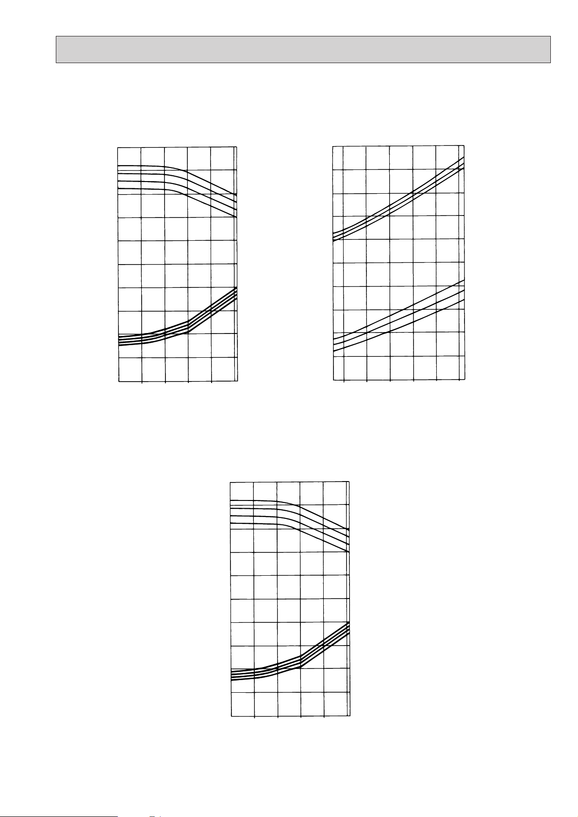
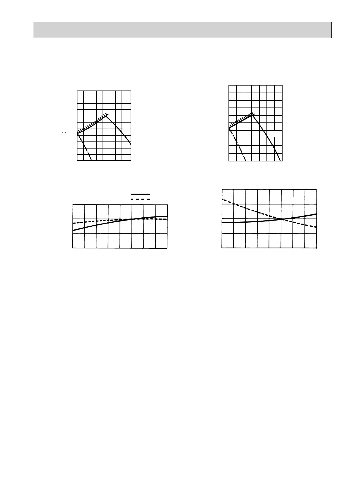
2. PERFORMANCE CURVE
PEHD-1.6~6EAKH.UK
1.4
1.2
1
0.8
CAPACITY(RATIO)
0.6
1.4
1.2
1
0.8
0.6
TOTAL INPUT(RATIO)
0.4
-5 5 15 25 35 46
Cooling
OUTDOOR DB
(˚C)
INDOOR WB
22
20
18
16
INDOOR WB
22
20
18
16
1.4
1.2
(˚C)
1
0.8
CAPACITY(RATIO)
0.6
1.4
(˚C)
1.2
1
0.8
0.6
TOTAL INPUT(RATIO)
0.4
-12 -10 -5 0 5 10 15
Heating
OUTDOOR WB
(˚C)
15
20
25
INDOOR DB
INDOOR DB
25
20
15
(˚C)
(˚C)
PED-2~6EAK.UK
1.4
1.2
1
0.8
CAPACITY(RATIO)
0.6
1.4
1.2
1
0.8
0.6
TOTAL INPUT(RATIO)
0.4
-5 5 15 25 35 46
Cooling
OUTDOOR DB
(˚C)
INDOOR WB
22
20
18
16
INDOOR WB
22
20
18
16
(˚C)
(˚C)
Page 18
18
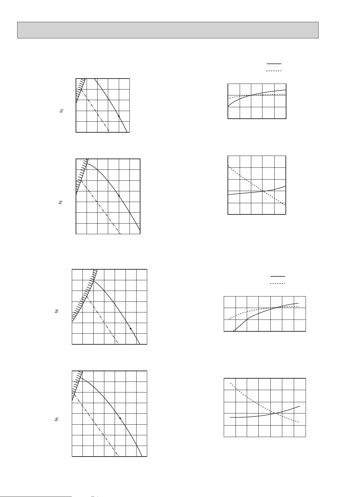
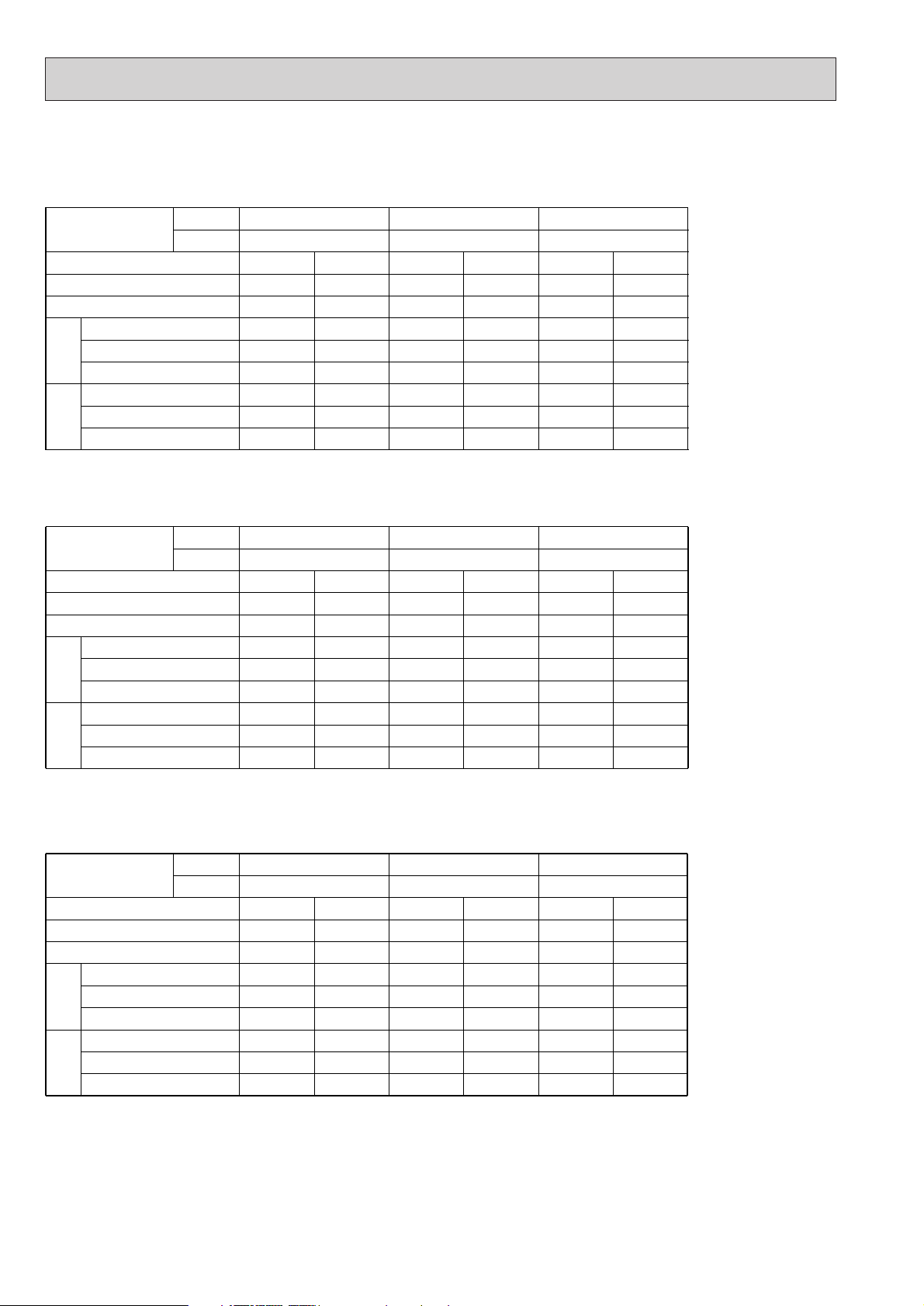
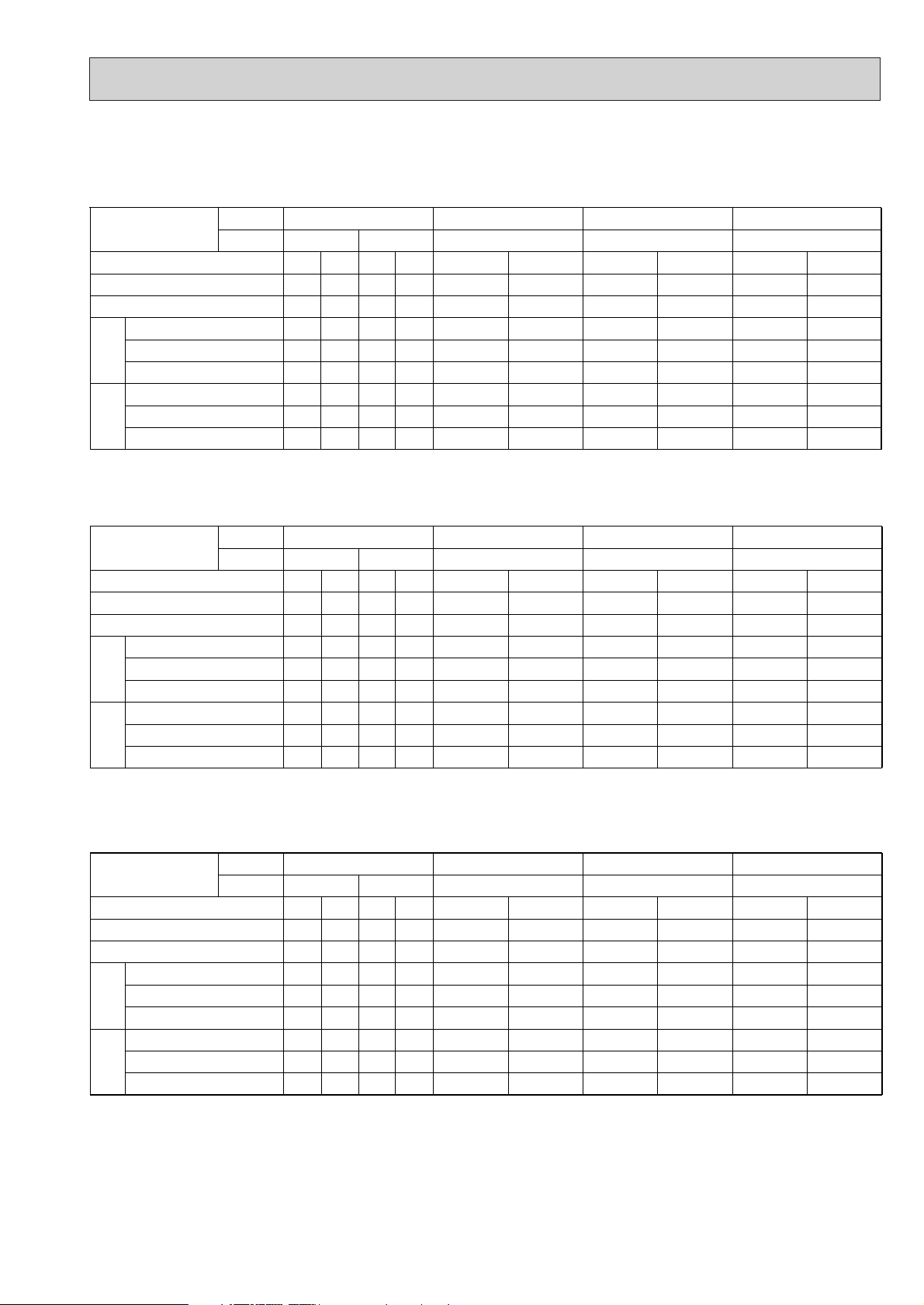
3. FAN PERFORMANCE AND CORRECTED AIR FLOW
Fan Performance <30Pa>
External static pressure (Pa)
(1Pa 0.1mmAg)
Air Flow (m3/min)
8610121416
6810121416
20
40
60
80
100
0.8
0.9
1.0
1.1
Corrected Air Flow
Capacity
input
Cooling
Air Flow (m
3
/min)
Correction factor
Fan Performance <70Pa>
External static pressure (Pa)
(1Pa 0.1mmAg)
Air Flow (m3/min)
10 1268 1416 18
681012 14 16
20
40
60
80
100
120
140
0.8
0.9
1.0
1.1
1.2
1.3
Heating
Air Flow (m
3
/min)
Correction factor
Lo
Hi
Lo
Hi
PEHD-1.6EAKH.UK
Fan Performance <30Pa>
External static pressure (Pa)
(1Pa 0.1mmAg)
Air Flow (m3/min)
681012 14 16 18 20
810121416182022
20
40
60
80
100
120
140
0.8
0.9
1.0
1.1
Corrected Air Flow
Capacity
input
Cooling
Air Flow (m
3
/min)
Correction factor
Fan Performance <70Pa>
External static pressure (Pa)
(1Pa 0.1mmAg)
Air Flow (m3/min)
810121416182022
810121416182022
20
40
60
80
100
120
140
160
0.8
0.9
1.0
1.1
1.2
1.3
Heating
Air Flow (m
3
/min)
Correction factor
Lo
Lo
Hi
Hi
PEHD-2EAKH.UK, PED-2EAK.UK
Page 19
19
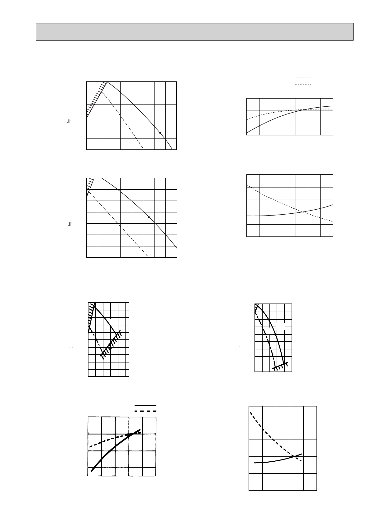
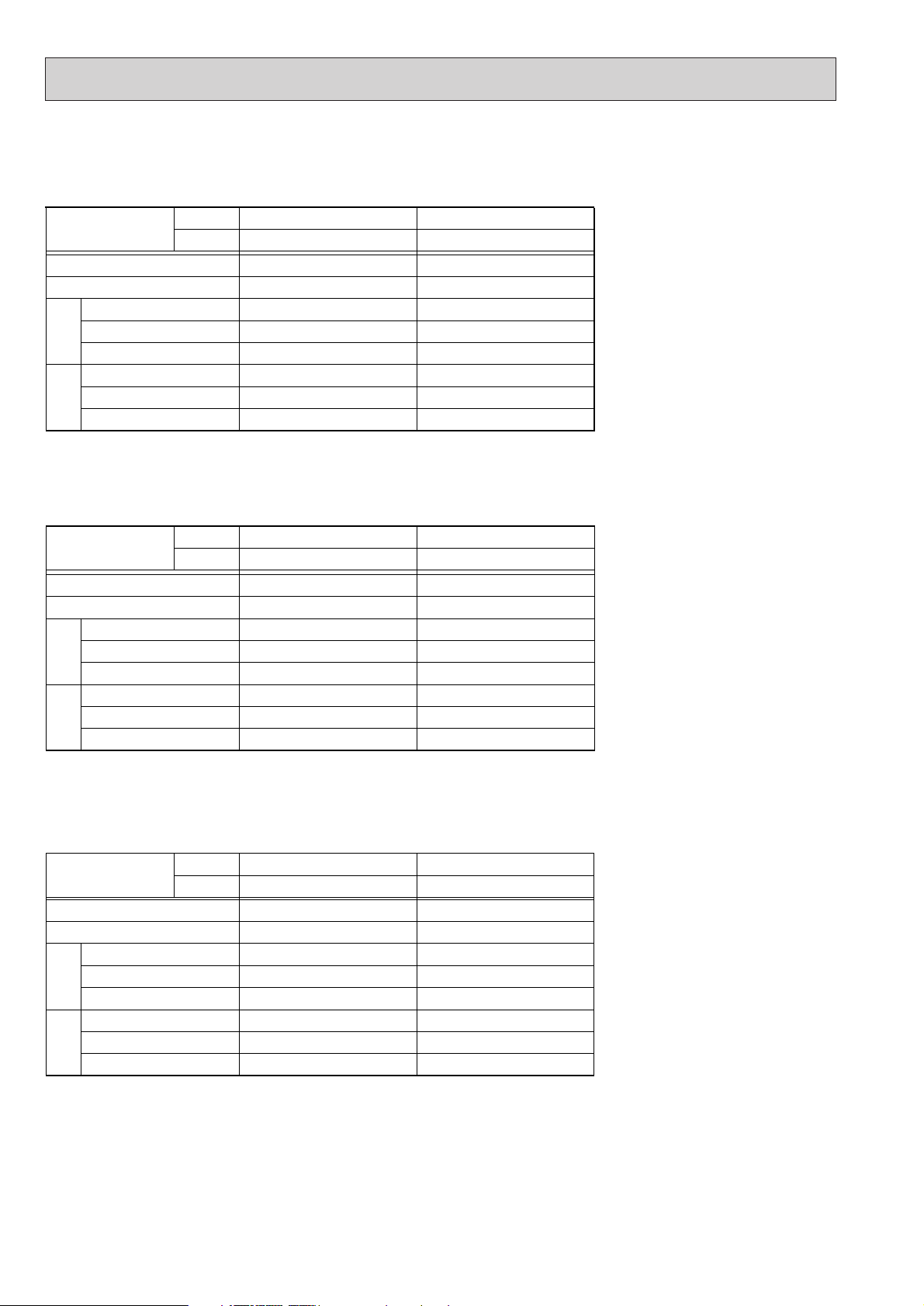
PEHD-3EAKH.UK, PED-3EAK.UK
PEHD-2.5EAKH.UK, PED-2.5EAK.UK
Lo
Hi
Fan Performance <30Pa>
External static pressure (Pa)
(1Pa 0.1mmAq)
Air Flow (m3/min)
81012141618202224
12 14 16 18 20 22 24 26
20
40
60
80
100
120
0.8
0.9
1.0
1.1
Corrected Air Flow
Capacity
input
Cooling
Air Flow (m
3
/min)
Correction factor
Fan Performance <70Pa>
External static pressure (Pa)
(1Pa 0.1mmAq)
Air Flow (m3/min)
10 12 14 16 18 20 22 24 26
12 14 16 18 20 22 24 26
20
40
60
80
100
120
140
0.8
0.9
1.0
1.1
1.2
1.3
Heating
Air Flow (m
3
/min)
Correction factor
Lo
Hi
Fan performance <130Pa>
200
180
160
140
120
100
80
=
60
(1Pa 0.1mmAq)
40
20
External static pressure (Pa)
12 16 20 24 28 32
Air Flow (m3/min)
Corrected Air Flow
Cooling
1.1
1.0
0.9
Lo
Hi
Capacity
Input
Fan performance <70Pa>
180
160
140
External static pressure (Pa)
120
100
80
=
60
40
(1Pa 0.1mmAq)
20
12 16 20 24 28 32
Air Flow (m3/min)
Heating
1.3
1.2
1.1
1.0
Lo
Hi
Correction factor
0.8
12 16 20 24 28 32
Air Flow (m3/min)
Correction factor
0.9
0.8
12 16 20 24 28 32
Air Flow (m3/min)
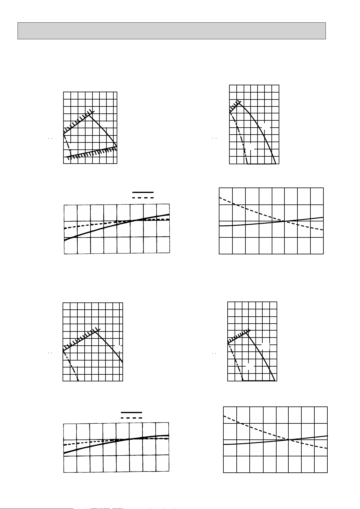
Page 20
20
140
120
100
200
180
160
80
60
40
20
26 28 30 32 34 36 38 40
Air Flow (m3/min)
Fan performance <130Pa>
External static pressure (Pa)
(1Pa 0.1mmAq)
140
120
100
200
220
180
160
80
60
40
20
24 26 28 30 32 34 36 38
Air Flow (m3/min)
Fan performance <70Pa>
External static pressure (Pa)
(1Pa 0.1mmAq)
Lo
Hi
Corrected Air Flow
Capacity
Input
1.1
1.0
0.9
0.8
24 26 28 30 32 34 36 38 40
Air Flow (m3/min)
Correction factor
Cooling
1.1
1.0
1.2
0.9
0.8
24 26 28 30 32 34 36 38 40
Air Flow (m3/min)
Correction factor
Heating
=
=
Lo
Hi
PEHD-4EAKH.UK, PED-4EAK.UK
PEHD-5EAKH.UK, PED-5EAK.UK
140
120
100
200
220
180
160
80
60
40
20
32 34 36 38 40 42 44 46 48
Air Flow (m3/min)
Fan performance <130Pa>
External static pressure (Pa)
(1Pa 0.1mmAq)
140
120
100
200
220
180
160
80
60
40
20
32 34 36 38 40 42 44 46
Air Flow (m3/min)
Fan performance <70Pa>
External static pressure (Pa)
(1Pa 0.1mmAq)
Lo
Hi
Corrected Air Flow
Capacity
Input
1.1
1.0
0.9
0.8
32 34 36 38 40 42 44 46 48
Air Flow (m3/min)
Correction factor
Cooling
1.1
1.0
1.2
0.9
0.8
32 34 36 38 40 42 44 46 48
Air Flow (m3/min)
Correction factor
Heating
=
=
Lo
Hi
Page 21
21
PEHD-6EAKH.UK, PED-6EAK.UK
Fan performance <130Pa>
220
200
180
160
140
120
100
=
80
60
(1Pa 0.1mmAq)
40
20
External static pressure (Pa)
Lo
38 40 42 44 46 48 50
36
Air Flow (m3/min)
Corrected Air Flow
Cooling
1.1
1.0
0.9
Correction factor
0.8
36 38 40 42 44 46
Air Flow (m3/min)
Hi
52
Capacity
Input
48 50
52
Fan performance <70Pa>
200
180
160
140
120
=
100
80
(1Pa 0.1mmAq)
60
40
External static pressure (Pa)
20
Lo
38 40 42 44 46 48
36
Air Flow (m3/min)
Heating
1.2
1.1
1.0
0.9
Correction factor
0.8
36 38 40 42 44 46
Air Flow (m3/min)
Hi
50
48
50 52
Page 22
Service Ref.
Indoor
Outdoor
Mode
Capacity(W)
Total input(kW)
Input(kW)
Current(A)
Starting current(A)
Input(kW)
Current(A)
Starting current(A)
IndoorOutdoor
Indoor ······220V 50Hz 1phase
Outdoor ··· 220V 50Hz 1phase
Service Ref.
Indoor
Outdoor
Mode
Capacity(W)
Total input(kW)
Input(kW)
Current(A)
Starting current(A)
Input(kW)
Current(A)
Starting current(A)
IndoorOutdoor
Indoor ······230V 50Hz 1phase
Outdoor··· 230V 50Hz 1phase
Service Ref.
Indoor
Outdoor
Mode
Capacity(W)
Total input(kW)
Input(kW)
Current(A)
Starting current(A)
Input(kW)
Current(A)
Starting current(A)
IndoorOutdoor
Indoor·······240V 50Hz 1phase
Outdoor··· 240V 50Hz 1phase
PEHD-2EAKH.UKPEHD-1.6EAKH.UK PEHD-2.5EAKH.UK
PUH-2VKA.TH PUH-2.5VKA.TH
PEHD-2.5EAKH.UK
PUH-2.5VKA.TH
PUH-1.6VKA.TH
Cool
6,600
2.56
0.15
0.69
1.53
2.41
11.18
48
Heat
7,100
(8,350)
2.31
(3.56)
0.15
(1.40)
0.69
(6.36)
1.53
(7.16)
2.16
10.02
48
Cool
6,700
2.60
0.16
0.70
1.56
2.44
10.94
50
Heat
7,150
(8,550)
2.36
(3.76)
0.16
(1.56)
0.70
(6.78)
1.56
(7.64)
2.20
9.86
50
Cool
4,300
1.48
0.12
0.55
0.92
1.36
6.79
30
Heat
4,500
(5,350)
1.44
(2.29)
0.12
(0.97)
0.55
(4.41)
0.92
(4.76)
1.32
6.59
30
Cool
5,500
2.25
0.13
0.60
1.05
2.12
9.83
41
Heat
6,100
(6,950)
2.27
(3.12)
0.13
(0.98)
0.60
(4.45)
1.05
(4.89)
2.14
9.93
41
PEHD-2EAKH.UKPEHD-1.6EAKH.UK
PUH-2VKA.THPUH-1.6VKA.TH
Cool
4,350
1.53
0.13
0.55
0.92
1.40
6.76
32
Heat
4,550
(5,450)
1.49
(2.39)
0.13
(1.03)
0.55
(4.48)
0.92
(4.83)
1.36
6.57
32
Cool
5,550
2.30
0.14
0.61
1.07
2.16
9.78
43
Heat
6,200
(7,100)
2.32
(3.22)
0.14
(1.04)
0.61
(4.52)
1.07
(4.96)
2.18
9.87
43
PEHD-2.5EAKH.UK
PUH-2.5VKA.TH
Cool
6,800
2.63
0.17
0.72
1.60
2.46
10.68
52
Heat
7,200
(8,700)
2.40
(3.90)
0.17
(1.67)
0.72
(6.96)
1.60
(7.84)
2.23
9.78
52
PEHD-2EAKH.UKPEHD-1.6EAKH.UK
PUH-2VKA.THPUH-1.6VKA.TH
Cool
4,400
1.57
0.13
0.55
0.92
1.44
6.74
33
Heat
4,600
(5,600)
1.54
(2.54)
0.13
(1.13)
0.55
(4.71)
0.92
(5.08)
1.41
6.60
33
Cool
5,600
2.35
0.15
0.63
1.10
2.20
9.86
45
Heat
6,300
(7,300)
2.37
(3.37)
0.15
(1.15)
0.63
(4.79)
1.10
(5.26)
2.22
9.95
45
22
4. ELECTRICAL DATA
Page 23
Service Ref.
Indoor
Outdoor
Mode
Capacity(W)
Total input(kW)
Input(kW)
Current(A)
Starting current(A)
Input(kW)
Current(A)
Starting current(A)
IndoorOutdoor
PUH-6YKSA.TH
PEHD-6EAKH.UK
Cool
14,300
5.20
0.56
2.59
5.75
4.64
8.10
68
Heat
15,800
(18,300)
5.12
(7.62)
0.56
(3.06)
2.59
(13.91)
5.75
(17.11)
4.56
7.96
68
Indoor ······220V 50Hz 1phase
Outdoor ··· 220/380V 50Hz 1/3phases
Service Ref.
Indoor
Outdoor
Mode
Capacity(W)
Total input(kW)
Input(kW)
Current(A)
Starting current(A)
Input(kW)
Current(A)
Starting current(A)
IndoorOutdoor
PUH-6YKSA.TH
PEHD-6EAKH.UK
Cool
14,500
5.30
0.61
2.69
6.00
4.69
7.87
71
Heat
15,900
(18,600)
5.18
(7.88)
0.61
(3.31)
2.69
(14.37)
6.00
(17.74)
4.57
7.67
71
Indoor ······230V 50Hz 1phase
Outdoor··· 230/400V 50Hz 1/3phases
Service Ref.
Indoor
Outdoor
Mode
Capacity(W)
Total input(kW)
Input(kW)
Current(A)
Starting current(A)
Input(kW)
Current(A)
Starting current(A)
IndoorOutdoor
PUH-6YKSA.TH
PEHD-6EAKH.UK
Cool
14650
5.39
0.66
2.79
6.25
4.73
7.74
74
Heat
16000
(19000)
5.24
(8.24)
0.66
(3.66)
2.79
(15.24)
6.25
(18.75)
4.58
7.50
74
Indoor·······240V 50Hz 1phase
Outdoor··· 240/415V 50Hz 1/3phases
PEHD-4EAKH.UKPEHD-3EAKH.UK PEHD-5EAKH.UK
PUH-4YKSA.TH
PUH-3YKA.TH
PUH-5YKSA.TH
PUH-3VKA.TH
Cool
12,200
4.73
0.54
2.50
5.50
4.19
7.32
49
Heat
13,700
(16,200)
4.67
(7.17)
0.54
(3.04)
2.50
(13.82)
5.50
(16.86)
4.13
7.21
49
Cool Heat
9,500
3.69
0.52
2.41
2.93
3.17
5.29
37
10,200
(12,200)
3.68
(5.68)
0.52
(2.52)
2.41
(11.45)
2.93
(12.02)
3.16
5.28
37
Cool
8,100
3.43
0.30
1.39
1.74
3.13
14.67
54
Heat
8,900
(10,700)
3.22
(5.02)
0.30
(2.10)
1.39
(9.55)
1.74
(9.92)
2.92
13.68
54
Cool
8,100
3.43
0.30
1.39
1.74
3.13
5.23
34
Heat
8,900
(10,700)
3.22
(5.02)
0.30
(2.10)
1.39
(9.55)
1.74
(9.92)
2.92
4.88
34
PEHD-4EAKH.UKPEHD-3EAKH.UK PEHD-5EAKH.UK
PUH-4YKSA.TH
PUH-3YKA.TH
PUH-5YKSA.TH
PUH-3VKA.TH
Cool
12,300
4.79
0.59
2.62
5.75
4.20
7.05
51
Heat
13,800
(16,500)
4.74
(7.44)
0.59
(3.29)
2.62
(14.30)
5.75
(17.49)
4.15
6.97
51
Cool
9,600
3.76
0.57
2.53
3.07
3.19
5.23
39
Heat
10,300
(12,500)
3.75
(5.95)
0.57
(2.77)
2.53
(12.64)
3.07
(12.64)
3.18
5.22
39
Cool
8,200
3.49
0.35
1.55
1.82
3.14
14.22
56
Heat
8,950
(10,850)
3.28
(5.18)
0.35
(2.25)
1.55
(9.78)
1.82
(10.08)
2.93
13.27
56
Cool
8,200
3.49
0.35
1.55
1.82
3.14
5.21
36
Heat
8,950
(10,850)
3.28
(5.18)
0.35
(2.25)
1.55
(9.78)
1.82
(10.08)
2.93
4.86
36
PEHD-4EAKH.UKPEHD-3EAKH.UK PEHD-5EAKH.UK
PUH-4YKSA.TH
PUH-3YKA.TH
PUH-5YKSA.TH
PUH-3VKA.TH
Cool
12,400
4.85
0.64
2.72
6.00
4.21
6.89
53
Heat
13,900
(16,900)
4.80
(7.80)
0.64
(3.64)
2.72
(15.17)
6.00
(18.50)
4.16
6.81
53
Cool
9,700
3.82
0.62
2.64
3.20
3.20
5.24
40
Heat
10,400
(12,800)
3.81
(6.21)
0.62
(3.02)
2.64
(12.58)
3.20
(13.20)
3.19
5.22
40
Cool
8,300
3.55
0.40
1.70
1.90
3.15
13.82
58
Heat
9,000
(11,100)
3.34
(5.44)
0.40
(2.50)
1.70
(10.41)
1.90
(10.65)
2.94
12.89
58
Cool
8,300
3.55
0.40
1.70
1.90
3.15
5.16
37
Heat
9,000
(11,100)
3.34
(5.44)
0.40
(2.50)
1.70
(10.41)
1.90
(10.65)
2.94
4.81
37
23
Page 24
Service Ref.
Indoor
Outdoor
Capacity(W)
Total input(kW)
Input(kW)
Current(A)
Starting current(A)
Input(kW)
Current(A)
Starting current(A)
IndoorOutdoor
Indoor ······220V 50Hz 1phase
Outdoor ··· 220V 50Hz 1phase
Service Ref.
Indoor
Outdoor
Capacity(W)
Total input(kW)
Input(kW)
Current(A)
Starting current(A)
Input(kW)
Current(A)
Starting current(A)
IndoorOutdoor
Indoor ······230V 50Hz 1phase
Outdoor··· 230V 50Hz 1phase
Service Ref.
Indoor
Outdoor
Capacity(W)
Total input(kW)
Input(kW)
Current(A)
Starting current(A)
Input(kW)
Current(A)
Starting current(A)
IndoorOutdoor
Indoor·······240V 50Hz 1phase
Outdoor··· 240V 50Hz 1phase
PED-2.5EAK.UKPED-2EAK.UK
PU-2VJA
1.TH
PED-2.5EAK.UKPED-2EAK.UK
PU-2.5VJA
1.TH
PU-2.5VJA
1.TH
PU-2VJA
1.TH
PED-2.5EAK.UKPED-2EAK.UK
PU-2.5VJA
1.THPU-2VJA1.TH
5,400
2.57
0.13
0.60
1.05
2.44
11.3
48
6,500
2.61
0.15
0.69
1.53
2.46
11.4
48
5,450
2.60
0.14
0.61
1.07
2.46
11.0
50
6,600
2.65
0.16
0.70
1.56
2.49
11.0
50
5,500
2.63
0.15
0.63
1.10
2.48
10.8
52
6,700
2.69
0.17
0.72
1.60
2.52
10.7
52
24
Page 25
Indoor ····· 220V 50Hz 1phase
Outdoor ··· 220/380V 50Hz 1/3phases
Indoor ····· 230V 50Hz 1phase
Outdoor ·· 230/400V 50Hz 1/3phases
Indoor ····· 240V 50Hz 1phase
Outdoor ·· 240/415V 50Hz 1/3phases
PED-5EAK.UKPED-4EAK.UK
12,300
5.20
0.59
2.62
5.75
4.61
7.89
65.5
9,600
3.90
0.57
2.53
3.07
3.33
5.6
38
9,600
4.01
0.57
2.53
3.07
3.44
16.6
79
PED-3EAK.UK
7,800
3.54
0.35
1.55
1.82
3.19
14.4
36
7,800
3.54
0.35
1.55
1.82
3.19
14.4
56
PED-6EAK.UK
14,700
5.76
0.61
2.69
6.00
5.15
8.56
74
PED-5EAK.UKPED-4EAK.UK
12,400
5.30
0.64
2.72
6.00
4.66
7.63
65.5
9,700
3.98
0.62
2.64
3.20
3.36
5.5
38
9,700
4.14
0.62
2.64
3.20
3.52
16.3
79
PED-3EAK.UK
7,900
3.60
0.40
1.70
1.90
3.20
5.3
37
7,900
3.60
0.40
1.70
1.90
3.20
13.9
58
PED-6EAK.UK
14,800
5.84
0.66
2.79
6.25
5.18
8.48
74
PU-5YJSA
1.TH
PU-4YJSA1.TH
PED-5EAK.UKPED-4EAK.UK
12,200
5.10
0.54
2.50
5.50
4.56
8.15
65.5
9,500
3.81
0.52
2.41
2.93
3.29
5.7
38
PU-4VLJSA2.TH
9,500
3.87
0.52
2.41
2.93
3.35
16.9
79
PU-3YJC.TH
PED-3EAK.UK
7,700
3.48
0.30
1.39
1.74
3.18
5.7
34
PU-3VJC1.TH
7,700
3.48
0.30
1.39
1.74
3.18
15.1
54
PU-6YJSA
1.TH
PU-5YJSA
1.TH
PU-4YJSA1.TH
PU-4VLJSA2.TH
PU-3YJC.TH
PU-3VJC1.TH
PU-6YJSA1.TH
PU-5YJSA
1.TH
PU-4YJSA1.TH
PU-4VLJSA2.TH
PU-3YJC.TH
PU-3VJC1.TH
PU-6YJSA1.TH
PED-6EAK.UK
14,600
5.67
0.56
2.59
5.75
5.11
8.63
74
Service Ref.
Indoor
Outdoor
Capacity(W)
Total input(kW)
Input(kW)
Current(A)
Starting current(A)
Input(kW)
Current(A)
Starting current(A)
IndoorOutdoor
Service Ref.
Indoor
Outdoor
Capacity(W)
Total input(kW)
Input(kW)
Current(A)
Starting current(A)
Input(kW)
Current(A)
Starting current(A)
IndoorOutdoor
Service Ref.
Indoor
Outdoor
Capacity(W)
Total input(kW)
Input(kW)
Current(A)
Starting current(A)
Input(kW)
Current(A)
Starting current(A)
IndoorOutdoor
25
Page 26

Service Ref.
Mode
TotalElectrical circuitRefrigerant circuit
Indoor side
Outdoor
side
SHF
BF
Capacity
Input
Indoor unit service ref.
Phase . Hz
Volts
Amperes
Outdoor unit service ref.
Phase,Hz
Volts
Amperes
W
kW
Discharge pressure
Suction pressure
Discharge temperature
Condensing temperature
Suction temperature
Ref.Pipe length
Intake air temperature
Intake air temperature
Discharge air temperature
MPa
MPa
˚C
˚C
˚C
m
DB˚C
WB˚C
DB˚C
DB˚C
WB˚C
Cooling Heating
6,800 7,200
2.63 2.40
PEHD-2.5EAKH.UK
1, 50
240
0.72 0.72
PUH-2.5VKA.TH
1, 50
240
PEHD-2.5EAKH.UK
Cooling Heating
5,600 6,300
2.35 2.37
PEHD-2EAKH.UK
1, 50
240
0.63 0.63
PUH-2VKA.TH
1, 50
240
PEHD-2EAKH.UK
Cooling Heating
4,400 4,600
1.57 1.54
PEHD-1.6EAKH.UK
1, 50
240
0.55 0.55
PUH-1.6VKA.TH
1, 50
240
6.74
1.76
0.54
76.6
47.1
8
5
27.0
19.0
15.4
35.0
24.0
0.74
0.21
6.6
1.51
0.41
66.8
-
0.2
5
20.0
15.0
35.1
7.0
6.0
-
-
9.86
1.93
0.47
87.3
51.2
4.8
5
27.0
19.0
14.5
35.0
24.0
0.76
0.19
9.95
2.15
0.37
101.4
-
-2.1
5
20.0
15.0
40.4
7.0
6.0
-
-
10.68
2.05
0.52
85
53.7
7.4
5
27.0
19.0
14.7
35.0
24.0
0.76
0.19
9.78
1.65
0.37
73.8
-
-2.4
5
20.0
15.0
39.1
7.0
6.0
-
-
PEHD-1.6EAKH.UK
26
5. STANDARD OPERATION DATA
Page 27
Service Ref.
Mode
TotalElectrical circuitRefrigerant circuit
Indoor side
Outdoor
side
SHF
BF
Capacity
Input
Indoor unit service ref.
Phase . Hz
Volts
Amperes
Outdoor unit service ref.
Phase,Hz
Volts
Amperes
W
kW
Discharge pressure
Suction pressure
Discharge temperature
Condensing temperature
Suction temperature
Ref.Pipe length
Intake air temperature
Intake air temperature
Discharge air temperature
MPa
MPa
˚C
˚C
˚C
m
DB˚C
WB˚C
DB˚C
DB˚C
WB˚C
PEHD-6
EAKH.UK
Cooling Heating
14,650 16,000
5.39 5.24
PEHD-6
EAKH.UK
1 . 50
240
2.79 2.79
PUH-6YKSA.TH
3.50
415
7.74 7.50
2.00 1.74
0.47 0.36
84.5 71.6
52.7
-
5.6 -2.3
55
27 20
19 15
14.2 40.1
35 7
24 6
0.77
-
0.11
-
Cooling Heating
12,400 13,900
4.85 4.80
PEHD-5
EAKH.UK
1 . 50
240
2.72 2.72
PUH-5YKSA.TH
3.50
415
6.89 6.81
1.88 1.70
0.51 0.37
75.8 74.3
48.8
-
6.8
55
27 20
19 15
15.1 37.0
35 7
24 6
0.85
-
0.13
-
Cooling Heating
7,700 9,000
3.55 3.34
PEHD-3EAKH.UK
1 . 50
240
1.70 1.70
PUH-3YKA.TH
3.50
415
5.16 4.81
2.00 1.84
0.45 0.34
86.3 81.7
52.1
-
4.8 -2.8
55
27 20
19 15
15.2 37.8
35 7
24 6
0.78
-
0.20
-
Cooling Heating
7,700 9,000
3.55 3.34
PEHD-3EAKH.UK
1 . 50
240
1.70 1.70
PUH-3VKA.TH
1.50
240
13.82 12.89
2.04 1.86
0.47 0.34
89.6 83.9
53.1
-
4.2 -3.8
55
27 20
19 15
15.3 37.8
35 7
24 6
0.78
-
0.21
-
Cooling Heating
9,700 10,400
3.82 3.81
PEHD-4EAKH.UK
1 . 50
240
2.64 2.64
PUH-4YKSA.TH
3.50
415
5.24 5.22
1.86 1.70
0.53 0.38
77.7 74.3
49.2
-
7.6 -1.3 -1.7
55
27 20
19 15
15.8 36.1
35 7
24 6
0.80
-
0.22
-
PEHD-4EAKH.UK
PEHD-3
EAKH.UK
PEHD-5
EAKH.UK
27
Page 28

Service Ref.
TotalElectrical circuitRefrigerant circuit
Indoor side
Outdoor
side
SHF
BF
Capacity
Input
Indoor unit service ref.
Phase Hz
Volts
Amperes
Outdoor unit service ref.
Phase,Hz
Volts
Amperes
W
kW
Discharge pressure
Suction pressure
Discharge temperature
Condensing temperature
Suction temperature
Ref.Pipe length
Intake air temperature
Intake air temperature
Diischarge air temperature
MPa
MPa
˚C
˚C
˚C
m
DB˚C
WB˚C
DB˚C
DB˚C
WB˚C
PED-2EAK.UK
5,500
2.63
PED-2EAK.UK
1, 50
240
0.63
PU-2VJA
1.TH
1, 50
240
10.8
1.98
0.46
77.3
52.5
15.3
5
27.0
19.0
14.8
35.0
24.0
0.74
0.32
PED-2.5EAK.UK
6,700
2.69
PED-2.5EAK.UK
1, 50
240
0.72
PU-2.5VJA
1.TH
1, 50
240
10.7
2.00
0.51
78.6
53.1
8.5
5
27.0
19.0
16.0
35.0
24.0
0.71
0.27
28
Page 29

Service Ref.
TotalElectrical circuitRefrigerant circuit
Indoor side
Outdoor
side
SHF
BF
Capacity
Input
Indoor unit service ref.
Phase Hz
Volts
Amperes
Outdoor unit service ref.
Phase,Hz
Volts
Amperes
W
kW
Discharge pressure
Suction pressure
Discharge temperature
Condensing temperature
Suction temperature
Ref.Pipe length
Intake air temperature
Intake air temperature
Diischarge air temperature
MPa
MPa
˚C
˚C
˚C
m
DB˚C
WB˚C
DB˚C
DB˚C
WB˚C
PED-5EAK.UK
12,400
5.30
PED-5EAK.UK
1.50
240
2.72
PU-5YJSA
1.TH
PU-4YJSA1.TH
3.50
415
7.63
1.84
0.40
82.9
49.3
0.3
5
27.0
19.0
15.5
35.0
24.0
0.85
0.13
9,700
4.14
1.50
240
2.64
PU-4VLJSA2.TH
1.50
240
16.3
1.80
0.52
82.1
48.5
8.1
5
27.0
19.0
15.7
35.0
24.0
0.80
0.22
9,700
3.98
1.50
240
2.64
3.50
415
5.5
1.81
0.52
74.0
48.7
8.5
5
27.0
19.0
16.0
35.0
24.0
0.80
0.22
PED-6EAK.UKPED-4EAK.UK
14,800
5.88
PED-6EAK.UKPED-4EAK.UK
PU-3YJC.TH
7,900
3.60
1.50
240
1.70
PU-3VJC1.TH
1.50
240
13.9
2.03
0.50
62.2
53.6
9.4
5
27.0
19.0
15.5
35.0
24.0
0.78
0.21
7,900
3.60
1.50
240
1.70
3.50
415
5.3
2.02
0.49
79.1
53.3
9.0
5
27.0
19.0
14.8
35.0
24.0
0.78
0.20
PED-3EAK.UK
PED-3EAK.UK
1.50
240
2.79
PU-6YJSA
1.TH
3.50
415
8.47
2.07
0.46
78.3
53.6
4.3
5
27.0
19.0
13.6
35.0
24.0
0.74
0.14
29
Page 30

2.5EAKH
1.6,2EAKH
EDCBA
-
1044
804
1070
830
290280
305772
1012
Model
B
35556
10
18
81
81
55
197
159
243
50~150
365~465
2
1
3
4
Air inlet
Air outlet
Access door
Service space:500 or more
Keep duct-work
length 850mm or more.
Be sure to apply the air filter (field supply) near the air inlet grille.
Refrigerant piping flare connection (liquid ø9.52 copper tube):HP
Refrigerant piping flare connection (gas ø15.88 copper tube):LP
Drain R1(External thread)
Electrical parts box
Electric Heater
Drain Pump (Option)
Drain Pipe (Option)···Flexible joint VP-25(I.D.ø32)
Filter
5
6
7
75
8
Air outlet
Air inlet
8
44
1234567
8
Lifting bolt hole
(14X22)
In case of rear inlet
In case of bottom inlet
10-
ø
3(1.6,2EAKH)
12-
ø
3(2.5EAKH)
10-ø3(1.6,2EAKH)
12-ø3(2.5EAKH)
(All around)
(All around)
(All around)
C
BC
C B
109
176
176
61
13
13
E
10
10
80
29
A
81
A
40
30
10
256
227
640
24
35
30
10
179
10
15
40
256
81
A
81
85
282
450
450
D 30
Set
277
45
10-
ø
3(1.6,2EAKH)
12-
ø
3(2.5EAKH)
21
3.52883.5
3.5
30
4
OUTLINES AND DIMENSIONS
4-1. INDOOR UNIT
PEHD-1.6, 2, 2.5EAKH
Unit : mm
Page 31

6EAKH
4,5EAKH
3EAKH
Model
1252
1012
280
360 370
1310 1284
ABCDE
19.05
F
290
1070 1044 15.88
1552
460 470
1610 1584 19.05
Keep duct-work
length 850mm or more.
Be sure to apply the air filter (field supply) near the air inlet grille.
Refrigerant piping flare connection (liquid ø9.52 copper tube):HP
Refrigerant piping flare connection (gas ø F copper tube):LP
Drain R1 (External thread)
Electrical parts box
Electric Heater
Drain Pump (Option)
Drain Pipe (Option)···Flexible joint VP25(I.D.ø32)
Filter
Air inlet
2
1
3
4
Air outlet
Access door
Service space:500 or more
5
6
7
8
243
75
13
50~150
55
44
323
81
365~465
308
81
197
1234567
8
Lifting bolt hole
(14X22)
12-
ø
3
113
307
12245
(All around)
(All around)
12-
ø
3
Set
D
E
30
13
80 375
1010
20
30
169
68030
261
40
53
A
81
A
81
210
35
10
282
450
450
B
BC
C
140
181
3.53193.5
29
30
31
PEHD-3, 4, 5, 6EAKH
Unit : mm
Page 32

2EAK
2.5EAK
Model
1012
772 305
280 290
830
1070
804
1044
-
ABCDE
7
Air inlet
Air outlet
7
44
75
6
5
Refrigerant piping flare connection (liquid
ø
9.52 copper tube):HP
Refrigerant piping flare connection (gas
ø
15.88 copper tube):LP
Drain R1(External thread)
Electrical parts box
Drain Pump (Option)
Drain Pipe (Option)···Flexible joint VP-25(I.D. ø32)
Air Filter
1234567
Service space:500 or more
Access door
Air outlet
Air inlet
4
3
1
2
365~465
50~150
243
159
197
55
81
81
18
10
56
B
355
Keep duct-work
length 850mm or more.
Be sure to change the position of air filter to the position where it can be serviced.
Service space:640 or more
10-
ø
3(2EAK)
12-
ø
3(2.5EAK)
In case of bottom inlet
In case of rear inlet
10-
ø
3(2EAK)
12-
ø
3(2.5EAK)
(14X22)
Lifting bolt hole
(All around)
(All around)
(All around)
45
277
Set
10-
ø
3(2EAK)
12-
ø
3(2.5EAK)
30D
450
450
282
85
81
A
81
256
40
15
10
179
10
30
35
24
640
227
256
10
30
40
A
81
A29
61
80
10
10
E
176
176
109
BC
C B
C
13
13
3.5
21
3.52883.5
32
PED-2, 2.5EAK
Unit : mm
Page 33

19.05
15841610
470460
1552
6EAK
10441070
290
EDCBA
12841310
370360
280
1012
1252
Model
4,5EAK
3EAK
F
15.88
7
6
5
Refrigerant piping flare connection (liquid ø9.52 copper tube):HP
Refrigerant piping flare connection (gas ø F copper tube):LP
Drain R1 (External thread)
Electrical parts box
Drain Pump (Option)
Drain Pipe (Option)···Flexible joint VP25(I.D.ø32)
Air Filter
Service space:500 or more
Access door
Air outlet
Air inlet
4
3
1
2
365~465
50~150
308
243
197
55
81
323
81
44 75
13
29
3.5
30
319
3.5
Keep duct-work
length 850mm or more.
Be sure to change the position of air filter to the position where it can
Service space:680 or more
1234567
12-ø3
(14X22)
Lifting bolt hole
113
307
45 122
(All around)
(All around)
12-ø3
450
450
282
10
30
210
35
20
261
A
81
81
A
30
53 169
40
30 680
80
10
10
181
140
C B
C B
375
13E
D
Set
be serviced.
33
PED-3, 4, 5, 6EAK
Unit : mm
Page 34

34
4-2. REMOTE CONTROLLER
130
120
19
Unit : mm
Page 35

TO MA-REMOTE
CONTROLLER
DC8.5-12V
TO OUTDOOR UNIT
X4
X6
X5
X1
FUSE
ZNR
P.B.
I.B.
BRN
ORN
YLW
SWITCH(EMERGENCY OPERATION)
SW6
1
2
OFF
ON
SW6
SW5
87654321
OFF
ON
ON
OFF
12345
SW1 SW5
Model selection
switch
System selection
switch
1
CN30
(BLK)
2
3
FB
NOTE 1.SINCE THE OUTDOOR SIDE ELECTRIC WIRING MAY CHANGE BE SURE
TO CHECK THE OUTDOOR UNIT ELECTRIC WIRING FOR SERVICING.
2.INDOOR AND OUTDOOR CONNECTING WIRES ARE MADE WITH POLARITIES,
MAKE WIRING MATCHING TERMINAL NUMBERS(1,2,3).
3.SYMBOLS USED IN WIRING DIAGRAM ABOVE ARE,
:CONNECTOR, :TERMINAL.
4.THE WIRING BETWEEN MA-REMOTE CONTROLLER AND TB5 IS INCLUDED
IN THE PACKAGE.
CONNECTOR(WIRELESS)
CN31
3
1
DRAIN SENSOR
DRAIN PUMP
(OPTIONAL PARTS)
DS
DP
DRAIN PUMP
HEATER CONTACTOR
88H1,2
HEATER THERMAL SWITCH
26H
HEATER
H
THERMAL FUSE
FS1,2
HEATER
N
L
TB2
PE
X4 X5 X6
X1
FAN
(WHT)
CNP
(BLU)
CNDK
(RED)
CND
13
(ORN)
BLU
RED
CN2L
LED2
LED1
(RED)
1
2
SW1
SWE
ON
OFF
SYMBOL
NAME
C
MF
TB5
TB4
TH1
TH2
CAPACITOR(FAN MOTOR)
FAN MOTOR
TERMINAL BLOCK(REMOTE CONTROLLER)
TERMINAL BLOCK
(INDOOR/OUTDOOR CONNECTING LINE)
INTAKE AIR TEMP. THERMISTOR
(0
˚C/15KΩ,25˚C/5.4KΩ DETECT)
PIPE TEMP. THERMISTOR/LIQUID
(0
˚C/15KΩ,25˚C/5.4KΩ DETECT)
SYMBOL
I.B.
CN2L
CN32
CN51
CN90
CN41
LED1
LED2
CONNECTOR(LOSSNAY)
POWER SUPPLY(I.B.)
INDOOR CONTROLLER BOARD
CONNECTOR(REMOTE SWITCH)
CONNECTOR(CENTRALLY CONTROL)
CONNECTOR(HA TERMINAL-A)
POWER SUPPLY(REMOTE CONTROLLER)
SYMBOL
FUSE(T6.3AL250V)
VARISTOR
FUSE
ZNR
NAME NAME
X6
X5
X4
SWE
SW5
SW1
RELAY(FAN MOTOR)
RELAY(FAN MOTOR)
RELAY(FAN MOTOR)
SWITCH(EMERGENCY OPERATION)
SWITCH(SYSTEM SELECTION)
SWITCH(MODEL SELECTION)
INDOOR POWER BOARD
P.B.
(RED)
(WHT)
(RED)
WHT
PNK
PNK
BLK
BLK
WHT
1
2
31
BLK
WHT
CN2S
CNSK
(WHT)
(RED)
BLK
WHT
YLW
ORN
BRN
BLU
BLU
WHT
BLK
CN2D
(WHT)
BLU
BLU
(BLU)
(RED)
(WHT)
(WHT)
(WHT)
(WHT)
(YLW)
(WHT)
(WHT)
DP
DS
643 521
C
MF
432
1
88H1
88H2
88H1
88H2
H
FS1 FS2
26H
RED
RED
RED
BLU
643 521
2
1
TB5
TB4
3
1
2
1331
643521
MF
C
1
2
CN24
3
21
12
3
1
2
1
2
TH2
TH1
1
2
1375
CN22
CN20 CN21
CN31
CN90
CN41
CN51
CN32
2
1
123456789
4
321
5
4
3
2
1
INSIDE SECTION OF CONTROL BOX
L
FERRITE CORE
CHOKE COILS
FB
L
X1
RELAY(DRAIN PUMP)
TB2 TERMINAL BLOCK(HEATER)
POWER SUPPLY
~(1PHASE)
230V 50Hz
<PEHD-1.6
.
2
.
2.5EAKH>
External static
pressure 70Pa
<PEHD-1.6
.
2
.
2.5EAKH>
External static
pressure 30Pa
<PEHD-3
.
4
.
5
.
6EAKH>
External static
pressure 70Pa
<PEHD-3
.
4
.
5
.
6EAKH>
External static
pressure 130Pa
Optional parts
Optional parts
35
5
WIRING DIAGRAM
PEHD-1.6, 2, 2.5, 3, 4, 5, 6EAKH
Page 36

TO OUTDOOR UNIT
TO MA-REMOTE
CONTROLLER
DC8.5-12V
I.B.
P.B.
ZNR
FUSE
X1
X5
X6
X4
BLU
RED
BRN
ORN
YLW
SWITCH(SYSTEM SELECTION)
SW6
SW5
SWITCH(EMERGENCY OPERATION)
54321
OFF
ON
678
ON
OFF
12345
System selection
switch
SW1
Model selection
switch
SW5
SW5
OFF
ON
1
2
SW6
CONNECTOR(HEATER)
CN24
POWER SUPPLY
~(1PHASE)
230V 50Hz
TERMINAL BLOCK(HEATER)TB2
RELAY(DRAIN PUMP)
X1
INSIDE SECTION OF CONTROL BOX
1
2
3
4
5
123
4
987654321
1
2
CN32
CN51
CN41
CN90
CN31
CN21CN20
CN22
5731
2
1
TH1 TH2
2
1
2
1
3
21
12
3
CN24
2
1
C
MF
12 534 6
1331
2
1
3
TB4
TB5
1
2
12 534 6
MF
C
12 534 6
DS
DP
(WHT)
(WHT)
(YLW)
(WHT)
(WHT)
(WHT)
(WHT)
(RED)
(BLU)
BLU
BLU
(WHT)
CN2D
BLK
WHT
BLU
BLU
BRN
ORN
YLW
WHT
BLK
(RED)
(WHT)
CNSK
CN2S
WHT
BLK
13
2
1
WHT
BLK
BLK
PNK
PNK
WHT
(RED)
(WHT)
(RED)
P.B.
INDOOR POWER BOARD
SWITCH(MODEL SELECTION)
SWITCH(EMERGENCY OPERATION)
RELAY(FAN MOTOR)
RELAY(FAN MOTOR)
RELAY(FAN MOTOR)
SW1
SWE
X4X5X6
NAMENAME
ZNR
FUSE
VARISTOR
FUSE(T6.3AL250V)
SYMBOL
POWER SUPPLY(REMOTE CONTROLLER)
CONNECTOR(HA TERMINAL-A)
CONNECTOR(CENTRALLY CONTROL)
CONNECTOR(REMOTE SWITCH)
INDOOR CONTROLLER BOARD
POWER SUPPLY(I.B.)
CONNECTOR(LOSSNAY)
LED2
LED1
CN41
CN90
CN51
CN32
CN2L
I.B.
SYMBOL
PIPE TEMP. THERMISTOR/LIQUID
(0
˚C/15KΩ,25˚C/5.4KΩ DETECT)
INTAKE AIR TEMP. THERMISTOR
(0˚C/15KΩ,25˚C/5.4KΩ DETECT)
TERMINAL BLOCK
(INDOOR/OUTDOOR CONNECTING LINE)
TERMINAL BLOCK(REMOTE CONTROLLER)
FAN MOTOR
CAPACITOR(FAN MOTOR)
TH2
TH1
TB4
TB5
MF
C
NAME
SYMBOL
OFF
ON
SWE
SW1
2
1
(RED)
LED1
LED2
CN2L
RED
BLU
(ORN)
31
CND
(RED)
CNDK
(BLU)
CNP
(WHT)
FAN
X1
X6X5X4
PE
TB2
L
N
DRAIN PUMP
DP
DS
(OPTIONAL PARTS)
DRAIN PUMP
DRAIN SENSOR
1
3
CN31
CONNECTOR(WIRELESS)
NOTE 1.SINCE THE OUTDOOR SIDE ELECTRIC WIRING MAY CHANGE BE SURE
TO CHECK THE OUTDOOR UNIT ELECTRIC WIRING FOR SERVICING.
2.INDOOR AND OUTDOOR CONNECTING WIRES ARE MADE WITH POLARITIES,
MAKE WIRING MATCHING TERMINAL NUMBERS(1,2,3).
3.SYMBOLS USED IN WIRING DIAGRAM ABOVE ARE,
:CONNECTOR, :TERMINAL.
4.THE WIRING BETWEEN MA-REMOTE CONTROLLER AND TB5 IS INCLUDED
IN THE PACKAGE.
3
2
(BLK)
CN30
1
Optional parts
Optional parts
<PED-3
.
4
.
5
.
6EAK>
External static
pressure 130Pa
<PED-3
.
4
.
5
.
6EAK>
External static
pressure 70Pa
<PED-2
.
2.5EAK>
External static
pressure 30Pa
<PED-2
·
2.5EAK>
External static
pressure 70Pa
36
PED-2, 2.5, 3, 4, 5, 6EAK
Page 37

Indoor unit
Indoor
heat
exchanger
Strainer
Restrictor
valve
Thermistor
TH2
Distributor
with strainer
Capillary
tube
PEHD-1.6(OD3.2xID1.6xL630)
PEHD-2(OD3.2xID1.8xL300)
PEHD-2.5(OD3.2xID1.8xL430)
PEHD-3(OD4.0xID2.0xL400)
PEHD-4(OD4.0xID2.4xL550)
PEHD-5(OD4.0xID2.4xL350)
PEHD-6(OD4.0xID2.4xL300)
Refrigerant flow in cooling R.V.coil
Refrigerant flow in heating Heating : ON
Cooling : OFF
Unit : mm
Strainer
Refrigerant pipe
(option)
9.52mm(3/8)
(With heat insulator)
Flexible tube
Flared
connection
Thermistor
RT2
Distributor
Refrigerant pipe
(option)
PED-2~3 : ø15.88mm(5/8)
PED-4~6 : ø19.05mm(3/4)
(With heat insulator)
Refrigerant pipe
(option)
PEHD-1.6~3 : ø15.88mm(5/8)
PEHD-4~6 : ø19.05mm(3/4)
(With heat insulator)
Refrigerant pipe
(option)
ø9.52mm(3/8)
(With heat insulator)
Indoor unit
Indoor
heat
exchanger
Flexible tube
Flared
connection
37
REFRIGERANT SYSTEM DIAGRAM6
PEHD-1.6~6EAKH.UK
PED-2~6EAK.UK
Page 38

38
7 TROUBLESHOOTING
<Error code display by self-diagnosis and actions to be taken for service (summary)>
Present and past error codes are logged and displayed on the wired remote controller or controller board of outdoor unit.
Actions to be taken for service,which depends on whether or not the the inferior phenomenon is reoccurring at service, are
summarized in the table below. Check the contents below before investigating details.
7-1. TROUBLESHOOTING
Unit conditions at service
Error code
Actions to be taken for service (summary)
The inferior phenomenon is
reoccurring.
Displayed
Not displayed
Judge what is wrong and take a corrective action
according to “SELF-DIAGNOSIS ACTION TABLE” (7-3).
Identify the cause of the inferior phenomenon and take
a corrective action according to “TROUBLESHOOTING
BY INFERIOR PHENOMENA ” (7-4).
The inferior phenomenon is
not reoccurring.
Logged
Not logged
1Consider the temporary defects such as the work of
protection devices in the refrigerant circuit including
compressor, poor connection of wiring, noise and etc.
Re-check the symptom, and check the installation
environment, refrigerant amount, weather when the
inferior phenomenon occurred, and wiring related.
2Reset error code logs and restart the unit after finishing
service.
3There is no abnormality in electrical components,
controller boards, and remote controller.
1Recheck the abnormal symptom.
2Identify the cause of the inferior phenomenon and take
a corrective action according to “TROUBLESHOOTING
BY INFERIOR PHENOMENA ” (7-4).
3Continue to operate unit for the time being if the cause
is not ascertained.
4There is no abnormality in electrical components,
controller boards, remote controller etc.
PAR-21MAA
ON/OFF
FILTER
CHECK
OPERATION
CLEAR
TEST
TEMP.
MENU
BACK DAY
MONITOR/SET
CLOCK
ON/OFF
ERROR CODE
ERROR CODE
ERROR CODE
1 Turn on the power.
2 Press the [CHECK] button twice.
3 Set address with [TEMP] button if system control is used.
4 Press the [ON/OFF] button to stop the self-check.
A CHECK button
B Address
C TEMP. button
D IC : Indoor unit
OC: Outdoor unit
E Check code
F Unit No.
G Timer ON/OFF button
A
F
C
BBEED
G
<To delete check code>
1 Display the error code at the self-check result display screen.
2 The address for self-check will blink when the
G ON/OFF
button is pressed twice within three seconds.
– – – – : No trouble generated in the past.
F F F F : No corresponding unit.
7-2. MALFUNCTION-DIAGNOSIS METHOD BY REMOTE CONTROLLER
<In case of trouble during operation>
When a malfunction occurs to air conditioner, both indoor unit and outdoor unit will stop and operation lamp blinks to inform
unusual stop.
■ Wired remote controller
Page 39
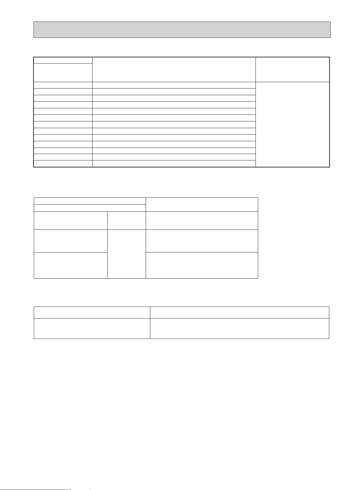
39
Errors detected by indoor unit
Wired remote controller
1 Check code
Symptom Remark
P1
Intake sensor error
P2 Pipe (TH2) sensor error
P4 Drain sensor error
P5
PA
Drain pump error
Forced compressor stop
P6 Freezing/ Overheating safeguard operation
P8 Pipe temperature error / Outdoor unit error
E4, E5 Remote controller signal receiving error
–
–
–
–
Fb Indoor unit control system error (memory error, etc.)
E0, E3
Remote controller transmission error
E1, E2 Remote controller control board error
• On wired remote controller
1Check code displayed in the LCD.
If the unit cannot be operated properly after test run has been performed, refer to the following table to remove the cause.
•
Wired remote controller
PLEASE WAIT
Symptom
For about 2
minutes following power-on
•For about 2 minutes following power-on,operation of the remote controller is not possible
due to system start-up. (Correct operation)
Cause
•Connector for the outdoor unit’s protection
PLEASE WAIT → Error code
Display messages do not
appear even when operation
switch is turned ON (operation
lamp does not light up).
After about 2
minutes has
expired following power-on
device is not connected.
•Reverse or open phase wiring for the outdoor
unit’s power terminal block
•Incorrect wiring between indoor and outdoor
units
•Remote controller wire short
Note:
Operation is not possible for about 30 seconds after cancellation of function selection. (Correct operation)
For description of each LED (LED1, 2) provided on the indoor controller, refer to the following table.
LED1 (power for microcomputer) Indicates whether control power is supplied. Make sure that this LED is
always lit.
LED2 (power for wired remote controller)
Indicates whether power is supplied to the wired remote controller.
This LED lights only in the case of the main indoor unit.
Page 40

40
7-3. SELF-DIAGNOSIS ACTION TABLE
Error Code
Meaning of error code and detection method
Cause
Countermeasure
P1
Abnormality of room temperature
thermistor (TH1)
1 The unit is in three-minute resume
prevention mode if short/open of
thermistor is detected. Abnormal if the
unit does not reset normally after three
minutes. (The unit returns to normal
operation, if it has normally reset.)
2 Constantly detected during cooling,
drying, and heating operation.
Short: 90
: or more
Open: -40
: or less
1 Defective thermistor
characteristics.
2 Contact failure of connector
(CN20) on the indoor controller
board. (Insert failure)
3 Breaking of wire or contact
failure of thermistor wiring.
4 Defective indoor controller
board.
1–3 Check resistance value of thermistor.
0
: ····15.0k"
10: ······9.6k"
20: ······6.3k"
30: ······4.3k"
40: ······3.0k"
If you put force on (draw or bend) the lead wire
with measuring resistance value of thermistor
breaking of wire or contact failure can be
detected.
2 Check contact failure of connector (CN20)
on the indoor controller board. Refer to 7-7.
Tu rn the power on again and check restart
after inserting connector again.
4 Check room temperature display on remote
controller.
Replace indoor controller board if there is
abnormal difference with actual room
temperature.
Tu rn the power off, and on again to operate
after check.
P2
Abnormality of pipe temperature
thermistor/Liquid (TH2)
1 The unit is in three-minute resume
prevention mode if short/open of
thermistor is detected. Abnormal if the
unit does not reset normally after three
minutes. (The unit returns to normal
operation, if it has normally reset.)
2 Constantly detected during cooling,
drying, and heating (except defrosting)
operation.
Short: 90
: or more
Open: -40
: or less
1 Defective thermistor
characteristics.
2 Contact failure of connector
(CN21) on the indoor controller
board. (Insert failure)
3 Breaking of wire or contact
failure of thermistor wiring.
4 Defective refrigerant circuit is
causing thermistor temperature
of 90
: or more or -40: or
less.
5 Defective indoor controller board.
1–3 Check resistance value of thermistor.
For characteristics, refer to (P1) above.
2 Check contact failure of connector (CN21)
on the indoor controller board. Refer to 7-7.
Tu rn the power on and check restart after
inserting connector again.
4 Check pipe <liquid> temperature with remote
controller in test run mode. If pipe <liquid>
temperature is exclusively low (in cooling
mode) or high (in heating mode), refrigerant
circuit may have defective.
5 Check pipe <liquid> temperature with remote
controller in test run mode. If there is exclusive
difference with actual pipe <liquid> temperature,
replace indoor controller board.
Tu rn the power off, and on again to operate
after check.
P4
Abnormality of drain sensor (DS)
1 Suspensive abnormality, if short/open of
thermistor is detected for 30 seconds
continuously.
Tu rn off compressor and indoor fan.
2 Short/open is detected for 30 seconds
continuously during suspensive
abnormality.
(The unit returns to normal operation,
if it has normally reset.)
3 Detect the following condition.
• During cooling and drying operation.
• In case that pipe <liquid> temperature
- room temperature <-10deg
(Except defrosting)
• When pipe <liquid> temperature or
room temperature is short/open
temperature.
• During drain pump operation.
1 Defective thermistor
characteristics
2 Contact failure of connector
(CN31) on the indoor controller
board. (Insert failure).
3 Breaking of wire or contact
failure of drain sensor wiring.
4 Defective indoor controller board.
1–3 Check resistance value of thermistor.
0
: ······6.0k"
10: ····3.9k"
20: ····2.6k"
30: ····1.8k"
40: ····1.3k"
2 Check contact failure of connector (CN31)
on the indoor controller board. Refer to 7-7.
Tu rn the power on again and check restart
after inserting connector again.
4 Replace indoor controller board if drain
pump operates with the line of drain sensor
connector CN31-
1 and 2 is short-circuited,
and abnormality reappears.
Tu rn the power off, and on again to operate
after check.
P5
Malfunction of drain pump (DP)
1 Suspensive abnormality, if thermistor
of drain sensor is let heat itself and
temperature rises slightly. Turn off
compressor and indoor fan.
2 Drain pump is abnormal if the condition
above is detected during suspensive
abnormality.
3 Constantly detected during drain pump
operation.
1 Malfunction of drain pump
2 Defective drain
Clogged drain pump
Clogged drain pipe
3 Attached drop of water at the
drain sensor
• Drops of drain trickles from
lead wire.
• Clogged filter is causing
wave of drain.
4 Defective indoor controller board.
1 Check if drain-up machine works.
2 Check drain function.
3 Check the setting of lead wire of drain
sensor and check clogs of the filter.
4 Replace indoor controller board if drain
pump operates with the line of drain sensor
connector CN31-1 and 2 is short-circuited
and abnormality reappears.
Refer to 7-7.
Tu rn the power off, and on again to operate
after check.
Page 41

41
Error Code
Meaning of error code and detection method
Cause
Countermeasure
P6
Freezing/overheating protection is
working
1 Freezing protection (Cooling mode)
The unit is in six-minute resume prevention
mode if pipe temperature stays under
-15: for three minutes, three minutes
after the compressor started. Abnormal
if it stays under -15: for three minutes
again within 16 minutes after six-minute
resume prevention mode.
<Frost prevention mode>
If pipe temperature is 1: or below
when 16 minutes has passed after compressor starts operating, unit will start
operating in frost prevention mode which
stops compressor operation. After that,
when pipe temperature stays 10: or
more for 3 minutes, frost prevention
mode will be released and compressor
will restart its operation.
P8
1 Slight temperature difference
between indoor room
temperature and pipe temperature thermistor
• Shortage of refrigerant
• Disconnected holder of pipe
thermistor
• Defective refrigerant circuit
2 Converse connection of
extension pipe (on plural units
connection)
3 Converse wiring of indoor/
outdoor unit connecting wire
(on plural units connection)
4 Defective detection of indoor
room temperature and pipe
temperature thermistor
5 Stop valve is not opened
completely.
(Cooling or drying mode)
1 Clogged filter (reduced airflow)
2 Short cycle of air path
3 Low-load (low temperature)
operation beyond the tolerance
range
4 Defective indoor fan motor
• Fan motor is defective.
• Indoor controller board is
defective.
5 Defective outdoor fan control
6 Overcharge of refrigerant
7 Defective refrigerant circuit
(clogs)
(Cooling or drying mode)
1 Check clogs of the filter.
2 Remove shields.
4 Measure the resistance of fan motor's winding.
Measure the output voltage of fan's connector
(FAN) on the indoor controller board.
WThe indoor controller board should be
normal when voltage of AC 220~240V is
detected while fan motor is connected.
Refer to 7-7.
5 Check outdoor fan motor.
67 Check operating condition of refrigerant
circuit.
Abnormality of pipe temperature
<Cooling mode>
Detected as abnormal when the pipe temperature is not in the cooling range 3 minutes later of compressor start and 6 minutes later of the liquid pipe is out of cooling
range.
Note 1) It takes at least 9 min. to detect.
Note 2) Abnormality P8 is not detected in
drying mode.
Cooling range : -5 deg
] (TH2-TH1)
TH2: Liquid pipe temperature
TH1: Intake temperature
1~4 Check pipe temperature with room
temperature display on remote
controller.
23Check converse connection of extension
pipe or converse wiring of indoor/outdoor
unit connecting wire.
1 Wrong wiring of indoor/outdoor
connecting wire
2 Reversed phase
3 Protection device is working
4 Damaged outdoor coil thermis-
tor
Abnormality in outdoor unit
1 Check the indoor/outdoor connecting wire.
2 Change the connection of electric wiring.
3 Check the protection device.
4 Measure the resistance of the outdoor coil
thermistor. If the resistance is normal,
replace the outdoor controller board.
Page 42

42
Error Code
Meaning of error code and detection method
Cause
Countermeasure
E0
or
E4
Remote controller transmission
error(E0)/signal receiving error(E4)
1 Abnormal if main or sub remote con-
troller can not receive normally any
transmission from indoor unit of refrigerant address “0” for three minutes.
(Error code : E0)
2 Abnormal if sub remote controller could
not receive for any signal for two minutes. (Error code: E0)
1 Abnormal if indoor controller board can
not receive normally any data from
remote controller board or from other
indoor controller board for three minutes.
(Error code: E4)
2 Indoor controller board cannot receive
any signal from remote controller for two
minutes. (Error code: E4)
1 Check disconnection or looseness of indoor
unit or transmission wire of remote controller.
2 Set one of the remote controllers “main”.
If there is no problem with the action above.
3 Check wiring of remote controller.
•Total wiring length: max.500m
(Do not use cable x 3 or more)
• The number of connecting indoor units:
max.16units
• The number of connecting remote controller: max.2units
When it is not the above-mentioned problem of
1~3
4 Diagnose remote controllers.
a) When “RC OK” is displayed,
Remote controllers have no problem.
Put the power off, and on again to check.
If abnormality generates again, replace
indoor controller board.
b) When “RC NG” is displayed,
Replace remote controller.
c) When “RC E3” is displayed,
d) When “ERC 00-06” is displayed,
[ c),d)→Noise may be causing abnormality. ]
∗ If the unit is not normal after replacing
indoor controller board in group control,
indoor controller board of address “0”
may be abnormal.
E3
or
E5
Remote controller transmission
error(E3)/signal receiving error(E5)
1 Abnormal if remote controller could not
find blank of transmission path for six
seconds and could not transmit.
(Error code: E3)
2 Remote controller receives transmitted
data at the same time, compares the
data, and when detecting it, judges
different data to be abnormal 30
continuous times. (Error code: E3)
1 Abnormal if indoor controller board could
not find blank of transmission path.
(Error code: E5)
2 Indoor controller board receives trans-
mitted data at the same time, compares
the data,and when detecting it, judges
different data to be abnormal 30
continuous times. (Error code: E5)
1 Set a remote controller to main, and the
other to sub.
2 Remote controller is connected with only one
indoor unit.
3 The address changes to a separate setting.
4~6 Diagnose remote controller.
a) When “RC OK”is displayed, remote con-
trollers have no problem.
Put the power off,and on again to check.
When becoming abnormal again, replace
indoor controller board.
b)When “RC NG”is displayed, replace
remote controller.
c)When “RC E3”or “ERC 00-66”is displayed,
noise may be causing abnormality.
1 Contact failure at transmission
wire of remote controller
2 All remote controllers are set
as “sub” remote controller. In
this case, E0 is displayed on
remote controller, and E4 is
displayed at LED (LED1, LED2)
on the outdoor controller circuit
board.
3 Mis-wiring of remote controller.
4 Defective transmitting receiving
circuit of remote controller
5 Defective transmitting receiving
circuit of indoor controller board
of refrigerant address “0”.
6 Noise has entered into the
transmission wire of remote
controller.
1 Tw o remote controller are set
as “main.”
(In case of 2 remote con-
trollers)
2 Remote controller is connected
with two indoor units or more.
3 Repetition of refrigerant
address.
4 Defective transmitting receiving
circuit of remote controller.
5 Defective transmitting receiving
circuit of indoor controller
board.
6 Noise has entered into trans-
mission wire of remote controller.
Page 43

43
Error Code
Meaning of error code and detection method
Cause
Countermeasure
Fb
Abnormality of indoor controller board
Abnormal if data cannot be normally read
from the nonvolatile memory of the indoor
controller board.
1 Defective indoor controller
board.
1 Replace indoor controller board.
E1
or
E2
Abnormality of remote controller control
board
1 Abnormal if data cannot be normally
read from the nonvolatile memory of the
remote controller control board.
(Error code: E1)
2 Abnormal if the clock function of remote
controller cannot be normally operated.
(Error code: E2)
1 Defective remote controller. 1 Replace remote controller.
PA
(2502)
(2500)
Forced compressor stop
(due to water leakage abnormality)
1 When the intake temperature subtracted
with liquid pipe temperature is less than
-10
:, drain sensor is detected whether
it is soaked in the water or not at the interval
of 90 seconds. (Drain pump will start operating
when the drain sensor is detected to be
soaked in the water.)
2 The unit has a water leakage abnormality
when the following conditions, a and b, are
satisfied while the above-mentioned detection
is performed.
a) The drain sensor is detected to be
soaked in the water 10 times in a row.
b) The intake temperature subtracted with
liquid pipe temperature is detected to be
less than -10
: for a total of 30 minutes.
(When the drain sensor is detected to
be NOT soaked in the water, the detection
record of a and b will be cleared.)
3 The drain sensor detection is performed
in operations other than cooling. (When
the unit stops operating, during heating
or fan operation, when the unit stops
because of some abnormality)
*Once the water leakage abnormality is
detected, abnormality state will not be
released until the main power is reset.
1 Drain pump trouble
2 Drain defective
· Drain pump clogging
· Drain pipe clogging
3 Open circuit of drain sensor
side heater
4 Contact failure of drain sensor
connector
5 Dew condensation on drain
sensor
· Drain water descends along
lead wire.
· Drain water waving due to filter
clogging.
6 Extension piping connection
difference at twin, triple,
quadruple system.
7 Mis-wiring of indoor/ outdoor
connecting at twin, triple,
quadruple system.
8 Room temperature thermistor /
liquid pipe temperature thermistor detection is defective.
1Check the drain pump.
Performance
2Please confirm whether water can be
drained.
3Confirm the resistance of the drain sensor
side heater.
4Check the connector contact failure.
5 Check the drain sensor leadwire mounted.
Check the filter clogging
6Check the piping connection.
7Check the indoor/ outdoor connecting wires.
8Check the room temperature display of
remote controller.
Check the indoor liquid pipe temperature
display of outdoor controller board.
Page 44

44
• When LED1 on indoor controller board is also off.
1 Power supply of 220~240V AC is not supplied to
indoor unit.
2 Defective indoor controller board.
3 Defective indoor power board.
7-4. TROUBLESHOOTING BY INFERIOR PHENOMENA
Phenomena
Cause
Countermeasure
(1)LED2 on indoor controller board
is off.
• When LED1 on indoor controller board is lit.
1 Mis-setting of main/sub for indoor unit
(There is no unit corresponding to main unit.)
1 Reconfirm the setting of main/sub for
indoor unit
Set the main unit.
Set main/sub using SW5-3 on indoor
controller board.
1 Check the voltage of indoor power supply
terminal block (L,N).
• When AC220~240V is not detected.
Check the power supply wiring.
• When AC220~240V is detected.
-Check 2 (below).
2 Check voltage output from CNDK on
indoor controller board.
• When AC220~240V is not detected.
Check the fuse on indoor controller
board.
Check the wiring connection between
indoor power supply terminal block and
CND on indoor controller board.
• When AC220~240V is detected.
-Check 3 (below).
3 Check voltage output from CN2S on
indoor power board.
• When no voltage output.
Check the wiring connection between
CNDK on indoor controller board and
CNSK on indoor power board.
If no problem are found,indoor power
board is defective.
• When DC12.5~13.7V is detected.
Check the wiring connection between
CN2S on indoor power board and
CN2D on indoor power board.
If no problem are found,indoor controller
board is defective.
(2)LED2 on indoor controller board
is blinking.
• When LED1 on indoor controller board is also blinking.
Connection failure of indoor/outdoor unit connecting
wire
• When LED1 is lit.
1 Mis-wiring of remote controller wires
When 2 indoor units are wired in one refrigerant
system, each indoor unit sets main unit. (SW5-3)
2 Short-cut of indoor/outdoor unit connecting wire.
3 Short-cut of remote controller wires
4 Defective remote controller
Check indoor/outdoor unit connecting wire
for connection failure.
1 Check the connection of remote con-
troller wires in case of twin triple indoor
unit system. When 2 or more indoor units
are wired in one refrigerant system,
connect remote controller wires to one of
those units.
2 Remove indoor/outdoor connecting wires
and check LED2 on indoor controller
board.
• When LED2 is blinking, check the shortcut of indoor/outdoor connecting wires.
• When LED2 is lit, connect indoor/outdoor
connecting wires again, and; if LED2 is
blinking, outdoor unit’s controller board is
defective; if LED2 is lit, connection failure
of indoor/outdoor terminal block etc. has
returned to normal.
34 Remove remote controller wires and
check LED2 on indoor controller board.
• When LED2 is blinking, check the
short-cut of remote controller wires.
• When LED2 is lit, connect remote
controller wires again and:
if LED2 is blinking, remote controller
is defective; if LED2 is lit, connection
failure of remote controller terminal
block etc. has returned to normal.
Page 45

45
(3)Upward/downward vane
performance failure
1 The vane is not downward during defrosting and
heat preparation and when the thermostat is OFF in
HEAT mode. (Working of COOL protection function)
2 Vane motor does not rotate.
• Defective vane motor
• Breaking of wire or connection failure of connector
• Up/down vane setting is “No vanes”.
3 Upward/downward vane does not work.
• The vane is set to fixed position.
1 Normal operation (The vane is set to hor-
izontal regardless of remote control.)
2 Check 2 (left).
• Check the vane motor. (Refer to “How
to check the parts”.)
• Check for breaking of wire or connection failure of connector.
• Check “Up/down vane setting”. (Unit
function selection by remote controller).
3 Normal operation (Each connector on
vane motor side is disconnected.)
Phenomena
Cause
Countermeasure
(4)Receiver for wireless remote
controller
1 Weak batteries of wireless remote controller.
2 Contact failure of connector (CNB) on wireless
remote controller board.
(Insert failure)
3 Contact failure of connector (CN90) on indoor con-
troller board.(Insert failure)
4 Contact failure of connector between wireless remote
controller board and indoor controller board.
1 Replace batteries of wireless remote con-
troller.
2~4
Check contact failure of each connector.
If no problems are found of connector,
replace indoor controller board.
When the same trouble occurs even if
indoor controller board is replaced,
replace wireless remote controller
board.
7-5. TEST RUN AND EMERGENCY OPERATION
7-5-1. Before test run
• After completing installation and the wiring and piping of the indoor and outdoor units, check for refrigerant leakage,
looseness in the power supply or control wiring, wrong polarity, and no disconnection of one phase in the supply.
• Use a 500-volt megohmmeter to check that the resistance between the power supply terminals and ground is
at least 1.0M".
• Do not carry out this test on the control wiring (low voltage circuit) terminals.
Warning:
Do not use the air conditioner if the insulation resistance is less than 1.0M".
7-5-2. Test run (Using wired remote controller)
B
EF
C
H
G
IM
A
D
ûC
ûC
SIMPLE
PAR-21MAA
ON/OFF
FILTER
CHECK
OPERATION
CLEAR
TEST
TEMP.
MENU
BACK DAY
MONITOR/SET
CLOCK
ON/OFF
TEST RUN
COOL, HEAT
A ON/OFF button
B Test run display
C Indoor temperature liquid line
temperature display
D ON/OFF lamp
E Power display
F Error code display
Test run remaining time display
G Set temperature button
H Mode selection button
I Fan speed button
M TEST button
1 Turn on the power at least 12 hours before the test run.
2 Press the [TEST] button twice. ➜ "TEST RUN" liquid crystal display
3 Press the [Mode selection] button. Make sure that wind is blown out.
4 Press the [Mode selection] button and switch to the cooling mode.
➜ Make sure that cold wind is blown out.
5 Press the [Fan speed] button. ➜ Make sure that the wind speed is switched.
6 Check operation of the outdoor unit fan.
7 Release test run by pressing the [ON/OFF] button. ➜ Stop
8 Register a telephone number.
The telephone number of the repair shop, sales office, etc., to contact if an error
occurs can be registered in the remote controller. The telephone number will be
displayed when an error occurs. For registration procedures, refer to the operation
manual for the indoor unit.
Page 46

46
1.When the wired remote control or the indoor unit microcomputer has failed,but all other components work if you set the
switch(SWE,SW6) on the indoor control board,the indoor unit will begin properly Emergency Operation.
2.When you activate emergency operation of the cooling, you have to set the connector(SWE) and switch(SW6)on the
indoor controller.
SWE:ON • Indoor fan is running high speed.
SW6-1:ON • Emergency operation of cooling mode.
3.Before you activate emergency operation,check the following points:
(1)Emergency operation cannot be activated when:
• the outdoor unit malfunctions.
• the indoor fan malfunctions.
(2)Emergency operation becomes continuous only by switching the power source on/off. ON/OFF on the remote
control or temperature control etc. does not function.
(3)Emergency cooling should be limited to 10 hours maximum
(The indoor unit heat exchanger may freeze).
(4)After emergency operation has been deactivated,set the switches etc. to their original positions.
7-5-3. When wired remote controller or indoor unit micro computer troubles
Page 47
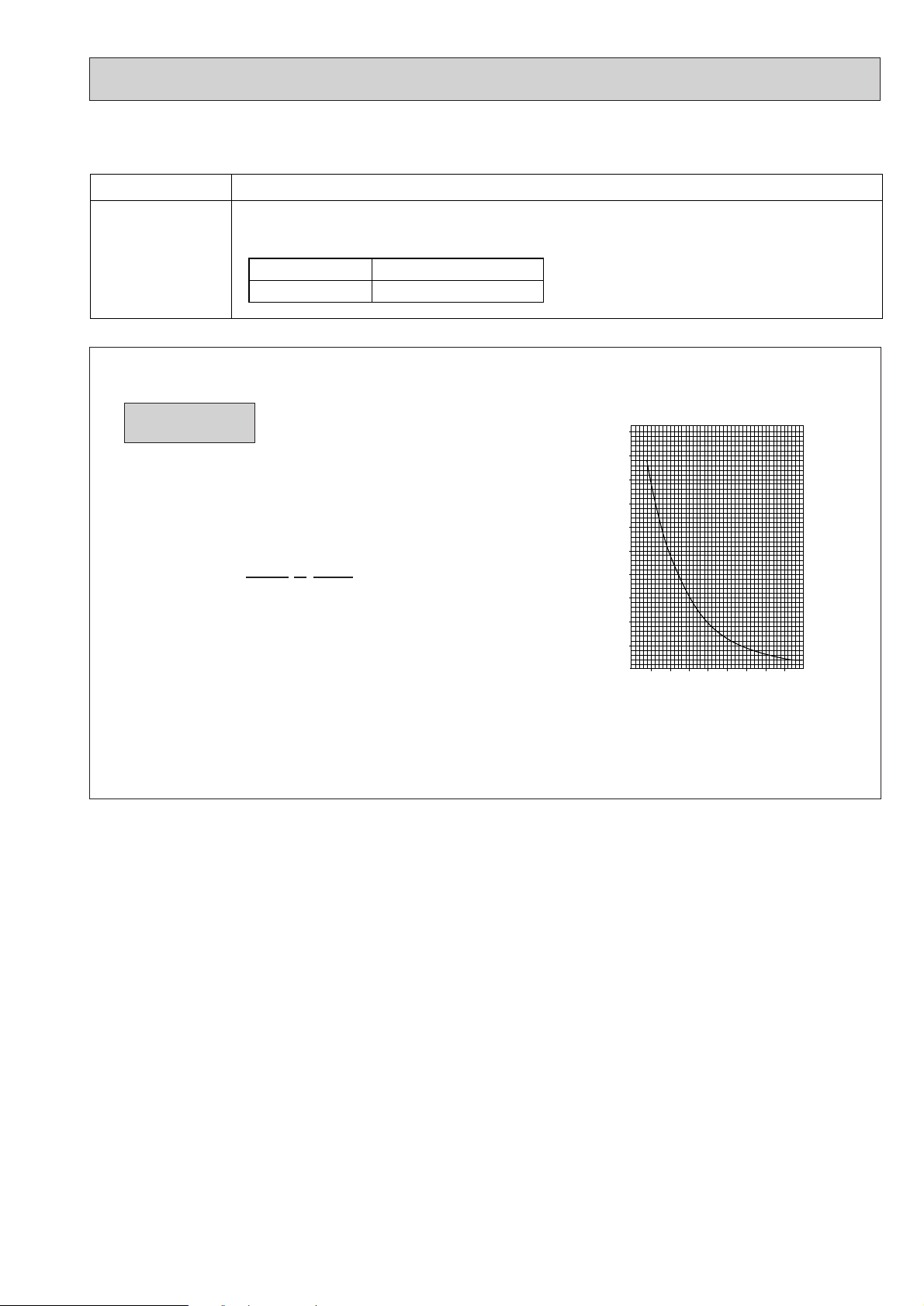
47
7-6. HOW TO CHECK THE PARTS
0
10
20
30
40
50
-20 -10 0 10 20 30 40 50
< Thermistor for lower temperature >
Temperature (:)
Resistance (K")
<Thermistor Characteristic graph>
Room temperature thermistor(TH1)
Pipe temperature thermistor(TH2)
Condenser/evaporator temperature
thermistor(TH5)
Thermistor R
0=15k" ±3%
Fixed number of B=3480k
" ±2%
Rt=15exp { 3480( ) }
0
: 15k"
10: 9.6k"
20: 6.3k"
25: 5.2k"
30: 4.3k"
40: 3.0k"
Thermistor for
lower temperature
1
273+t
1
273
Par ts name Check points
Disconnect the connector then measure the resistance using a tester.
(Surrounding temperature 10:~30:)
(Refer to the thermistor)
Room temperature
thermistor (TH1)
Pipe temperature
thermistor (TH2)
Normal
4.3k"~9.6k"
Abnormal
Open or short
Page 48

48
7-7. TEST POINT DIAGRAM
7-7-1. Power board
CNSK
Connect to the indoor controller board
(CNDK)
Between
1 to 3 220-240V AC
CN2S
Connect to the indoor controller board (CN2D)
Between
1 to 3 12.6-13.7V DC (Pin1 (+))
Page 49

49
7-7-2. Indoor controller board
FAN
Fan motor output
CNP
Drain-pump output
(DP)
(220~240V AC)
CNC
Dew prevention
heater (H2)
(220~240V AC)
CNDK
Connect to the indoor
power board (CNSK)
(220~240V AC)
FUSE
(6.3A 250V)
CND
Power
supply input
(220~240V AC)
SWE
Emergency operation
SW1
Model setting
CN2L
Connector
(LOSSNAY)
CN51
Centrally control
CN6V
Vane motor output
(MV)
CN90
Connect to the wireless remote controller board (CNB)
CN31
Drain sensor (DS)
CN21
Pipe temperature
thermistor/Liquid
(TH2)
CN20
Room temperature
thermistor (TH1)
CN22
Remote controller
connecting wire
(10.4~14.6V DC)
LED2
Power supply
(R.B)
LED1
Power supply
(I.B)
CN2D
Connector to the indoor
power board (CN2S)
(12.5~13.7V DC)
}
}
+
–
+
–
SW5
System Setting
CN32
Remote Switch
CN41
Connector
(HA terminal-A)
CN105/ CN92
(RED)
SW6
Emergency
operation
CN30
Tr ansmission
(indoor/outdoor)
Page 50

50
SW1
Setting by the dip switch and jumper wire
Service board
Models
PEHD
PED
Functions
Jumper wire
Model
settings
SW5
System
settings
Pair number
setting with
wireless
remote
controller
Remarks
J41
J42
0
1
2
3 ~ 9
Wireless remote
controller setting
Control PCB setting
J41 J42
<Settings at time of factory shipment>
Wireless remote controller: 0
Control PCB: (for both J41 and J42)
Four pair number settings are supported.
The pair number settings of the wireless remote
controller and indoor control PCB (J41/J42) are
given in the table on the left.
(' ' in the table indicates the jumper line is disconnected.)
(Marks in the table below) Jumper wire ( : Short : Open)
SW5-3 Main/Sub setting
OFF : Main ON : Sub
SW5-4 Rotaion operation setting
OFF : Not avairable ON : avairable
OFF
ON
54321
SW1
OFF
ON
54321
OFF
ON
54321
7-8. FUNCTIONS OF DIP SWITCH AND JUMPER WIRE
Each function is controlled by the dip switch and the jumper wire on control p.c. board.
Page 51
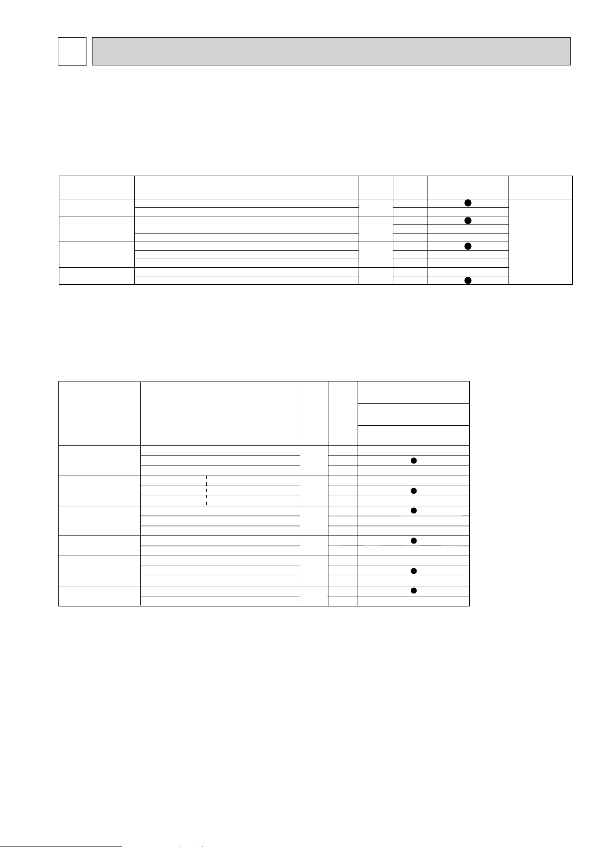
51
8
FUNCTION SETTING
Function Settings Mode
No.
Setting
No.
Initial setting (Factory setting
)
- : Not available
Ceiling concealed
PE(H)D-EAK(H)
Filter sign 100Hr 1
2500Hr 07 2
No filter sign indicator
3
Air flow Quiet Standard 1
-
-
-
(
Fan speed
)
Standard
High ceiling1
08 2
High ceiling
High ceiling2
3
No.of air outlets 4 directions 1
3 directions 09 2
2 directions
3
Optional high
Not supported
10
1
efficiency filter
Supported
2
Vane setting
No vanes (Vane No.3 setting:PL-AAKonly
)
1
Vane No.1 setting
11 2
Vane No.2 setting
3
Energy saving air
Disabled
12
1
flow (Heating mode
)
Enabled
2
-
-
-
-
-
-
-
}
PL-AAK
Function
Settings
Mode No.
Setting No.
Initial setting
(when sent from the factory)
Remarks
Power failure
automatic recovery
Indoor temperature
detecting
LOSSNAY
connectivity
Power supply
voltage
OFF
ON
Indoor unit's (Main) internal sensor
Remote controller's internal sensor w1
Not supported
Supported (indoor unit not equipped with outdoor air intake)
Supported (indoor unit equipped with outdoor air intake)
240V
220V,230V
1
2
1
2
3
1
2
3
1
2
01
02
03
04
The setting is
applied to all
the units in the
same
refrigerant
system.
8-1. UNIT FUNCTION SETTING BY THE REMOTE CONTROLLER
Each function can be set according to necessity using the remote controller. The setting of function for each unit can only be
done by the remote controller. Select function available from the table 1.
(1) Functions available when setting the unit number to 00 (Select 00 referring to
4 setting the indoor unit number.)
W1 The functions below are available only when the wired remote controller is used.The functions are not available for floor
standing models.
<Table 1> Function selections
(2) Functions available when setting the unit number to 01-02 or AL (07 in case of wireless remote controller)
• When setting functions for an indoor unit in an independent system, set the unit number to 01 referring to
4 setting the
indoor unit number.
• When setting functions for a simultaneous Twin-indoor unit system, set the unit number to 01 to 02 for each indoor
unit in case of selecting different functions for each unit referring to
4 setting the indoor unit number.
• When setting the same functions for an entire simultaneous Twin-indoor unit system, set refrigerant address to AL
(07 in case of wireless remote controller) referring to
4 setting the indoor unit number.
Page 52

52
8-1-1. Selecting functions using the wired remote controller
First, try to familiarize yourself with the flow of the function selection procedure. In this section, an example of setting the room
temperature detection position is given.
For actual operations, refer to steps 1 to 0 .
Setting number
Mode number
F
Address Unit number
I
A
E
G
C
D
Modes 01 to 14 can be activated
by pressing buttons
B
simultaneously, and modes 15 to
28 by pressing buttons
J
A
B
and
B
and J.
Page 53

53
Selecting functions using the wired remote controller
1
Check the function selection setting.
2
Switch to function setting mode.
(Press
A
and B at the same time
For modes 15 and higher,
press
with the remote controller stopped.)
3
Specify address
4
Specify unit No.
(Use C and D.)
Refer to address unit No. to the figure below
J
and B at the same time.
5
Enter the setting.
(Press
6
Select mode No. 02
E
.)
(Specified indoor unit:
BLOW operation)
(room temperature detection position).
7
Select setting No. 03 (remote controller fixed).
(Use
F
and G.)
8
Enter the setting.
(Press
E
.)
Example:
Selecting room temperature
detection position
NO
Finished
YES
0
Ending function display
(Press
A
and B at the same time.)
The above procedure must be carried out only if changes are necessary.
NO
YES
Change refrigerant
address unit No.
9
1 : 1 system Simultaneous twin system Rotation system
Outdoor unit
Indoor unit
Remote controller
Indoor unit
address = 00
unit No. = 01
Main
indoor unit
Main indoor unit
address = 00
unit No. = 01
Outdoor unit Outdoor unit Outdoor unit
Sub
indoor unit
Remote controller
Sub indoor unit
address = 01
unit No. = 02
Main
indoor unit
Main indoor unit
address = 00
unit No. = 01
Remote controller
Sub indoor unit
address = 01
unit No. = 01
Sub
indoor unit
Page 54

54
[Operating Procedure]
1 Check the setting items provided by function selection.
If settings for a mode are changed by function selection, the functions of that mode will be changed accordingly. Check all the current settings according to steps 2
to 7 , fill in the "Check" column in Table 1, and then change them as necessary. For factory settings, refer to the indoor unit's installation manual.
2 Switch off the remote controller.
A Hold down the
buttons
and then the remote controller's display content will change as shown below.
* If the unit stops after
Check to see if there are any sources of noise or interference near the transmission path.
Note
If you have made operational mistakes during this procedure, exit function selection (see step 0 ), and then restart from step 2 .
4 Set the indoor unit number.
D Press the
area.
FILTER
simultaneously for at least two seconds.
Address
display section
FUNCTION
flashed for two seconds or "88" flashes in the room temperature display area for two seconds, a transmission error may have occurred.
SELECTION
ON/OFF
button so that "- -" flashes in the unit number display
Unit number
display section
FUNCTION
SELECTION
B ( mode 15 or more) and
TEST
will start to flash,
3 Set the outdoor address.
C Press the [
address. The address changes from "00" to "15".
C Press the [
of the indoor unit for which you want to perform function selection. The unit
number changes to "00", "01", "02","03",04" and "AL" each time a button is
pressed.
CLOCK] buttons ( and ) to select the desired
CLOCK] buttons ( and ) to select the unit number
* To set modes 01 to 06 or 15 to 22 select unit number "00".
* To set modes 07 to 14 or 23 to 28 carry out as follows:
• To set each indoor unit individually, select "01" to "04".
• To set all the indoor units collectively, select "AL".
5 Confirm the address and unit number.
E Press the
number.
After a while, "- - " will start to flash in the mode number display area.
Mode number
display section
* "88" will flash in the room temperature display area if the selected address
does not exist in the system.
Furthermore, if
address display area also flashes, there are no units that correspond to the
selected unit number. In this case, the address and unit number may be incorrect,
so repeat steps 2 and 3 to set the correct ones.
6 Select the mode number.
F Press the [
number.
(Only the selectable mode numbers can be selected.)
7 Select the setting content for the selected mode.
G Press the
flash, so check the currently set content.
8 Register the settings you have made in steps 3 to 7.
E Press the
to flash and registration starts.
MODE
button to confirm the address and unit
MODE
"F"
appears and flashes in the unit number display area and the
TEMP] buttons ( and ) to set the desired mode
button. The currently selected setting number will
MENU
Setting number display section
button. The mode number and setting number will start
Setting number 1 = Indoor unit operating average
E When the address and unit number are confirmed by pressing the
button, the corresponding indoor unit will start fan operation. This
MODE
helps you find the location of the indoor unit for which you want to perform function
selection. However, if "00" or "AL" is selected as the unit number, all the indoor
units corresponding to the specified address will start fan operation.
Example) When the address is set to 01 and the unit number is 02.
00 address
Outdoor unit
Indoor unit
Designate operation
* When grouping different systems, if an indoor unit other than the
one to which the address has been set performs fan operation,
there may be another address that is the same as the specified one.
In this case, check the DIP switch of the outdoor unit to see
whether such a address exists.
Mode number
display section
F Press the [
number.
The mode number and setting number will stop flashing and remain lit, indicating the
end of registration.
TEMP] buttons ( and ) to select the desired setting
Main Sub
Remote controller
Mode number 02 = Indoor temperature detection
Setting number 3 = Remote controller built-in sensor
Fan draft
* If " - - - " is displayed for both the mode number and setting number and "
Check to see if there are any sources of noise or interference near the transmission path.
9 If you wish to continue to select other functions, repeat steps 3 to 8.
0 Complete function selection.
A Hold down the
buttons simultaneously for at least two seconds.
After a while, the function selection screen will disappear and the air conditioner OFF screen will reappear.
Note If a function of an indoor unit is changed by function selection after installation is complete, make sure that a " " mark, etc., is given in the "Check"
column of Table 1 to indicate the change.
( mode 15 or more) and
FILTER TEST
" flashes in the room temperature display area, a transmission error may have occurred.
* Do not operate the remote controller for at least 30 seconds after completing
function selection. (No operations will be accepted even if they are made.)
Page 55

55
8-2. FUNCTION SELECTION OF REMOTE CONTROLLER
The setting of the following remote controller functions can be changed using the remote controller function selection mode.
Change the setting when needed.
Item 1
1.Change Language
("CHANGE LANGUAGE")
2.Function limit
("FUNCTION SELECTION")
3.Mode selection
("MODE SELECTION")
4.Display change
("DISP MODE SETTING")
Item 3 (Setting content)
• Display in multiple languages is possible.
• Setting the range of operation limit (operation lock)
• Setting the use or non-use of "automatic" operation mode
• Setting the temperature adjustable range (maximum, minimum)
• Selecting main or sub remote controller
*
When two remote controllers are connected to one group, one controller must be set to sub.
• Setting the use or non-use of clock function
• Setting the timer type
• Contact number display in case of error
• Setting the telephone number
• Setting the temperature unit (: or °F) to display
• Setting the use or non-use of the display of indoor (suction) air temperature
• Setting the use or non-use of the display of "Cooling" or "Heating" display during
operation with automatic mode
Item 2
Language setting to display
(1)
Operation function limit setting (operation lock) ("LOCKING FUNCTION")
(2)
Use of automatic mode setting ("SELECT AUTO MODE")
(3)
Temperature range limit setting ("LIMIT TEMP FUNCTION")
(1)
Remote controller main/sub setting ("CONTROLLER MAIN/SUB")
(2) Use of clock setting ("CLOCK")
(3) Timer function setting ("WEEKLY TIMER")
(4) Contact number setting for error situation ("CALL.")
(1) Temperature display :/°F setting ("TEMP MODE :/°F")
(2)
Suction air temperature display setting ("ROOM TEMP DISP SELECT")
(3)
Automatic cooling/heating display setting ("AUTO MODE DISP C/H")
[Function selection flowchart] Refer to next page.
[1] Stop the air conditioner to start remote controller function selection mode. [2] Select from item1. [3] Select from item2. [4] Make the setting.
(Details are specified in item3) [5] Setting completed. [6] Change the display to the normal one. (End)
➔➔➔
➔➔
[Detailed setting]
[4] -1. CHANGE LANGUAGE setting
The language that appears on the dot display can be selected.
• Press the [
MENU] button to change the language.
1 Japanese (JP), 2 English (GB), 3 German (D), 4 Spanish (E),
5 Russian (RU), 6 Italian (I), 7 Chinese (CH), 8 French (F)
[4] -2. Function limit
(1) Operation function limit setting (operation lock)
• To switch the setting, press the [ ON/OFF] button.
1 no1 : Operation lock setting is made on all buttons other than
the [
ON/OFF] button.
2 no2 : Operation lock setting is made on all buttons.
3 OFF (Initial setting value) : Operation lock setting is not made
* To make the operation lock setting valid on the normal screen, it is
necessary to press buttons (Press and hold down the [FILTER]
and [
ON/OFF] buttons at the same time for two seconds.) on
the normal screen after the above setting is made..
(2) Use of automatic mode setting
When the remote controller is connected to the unit that has automatic operation mode, the following settings can be made.
• To switch the setting, press the [ ON/OFF] button.
1 ON (Initial setting value) : The automatic mode is displayed when
the operation mode is selected.
2 OFF : The automatic mode is not display
when the operation mode is selected.
[4] -3. Mode selection setting
(1) Remote controller main/sub setting
•To switch the setting, press the [ ON/OFF] button.
1 Main : The controller will be the main controller.
2 Sub : The controller will be the sub controller.
(2) Use of clock setting
•To switch the setting, press the [ ON/OFF] button.
1 ON : The clock function can be used.
2 OFF : The clock function cannot be used.
(3) Timer function setting
•To switch the setting, press the [ ON/OFF] button (Choose one of
the followings.).
1 WEEKLY TIMER (initial setting on MA deluxe):
The weekly timer can be used.
2 AUTO OFF TIMER: The auto off timer can be used.
SIMPLE TIMER (Default setting on MA smooth):
The simple timer can be used.
43TIMER MODE OFF: The timer mode cannot be used.
* When the use of clock setting is OFF, the "WEEKLY TIMER" cannot be
used.
(4) Contact number setting for error situation
•To switch the setting, press the [ ON/OFF] button.
1 CALL OFF :
The set contact numbers are not displayed in case of error.
2 CALL **** *** **** : The set contact numbers are displayed in case
of error.
(3) Temperature range limit setting
After this setting is made, the temperature can be changed within the set range.
• To switch the setting, press the [ ON/OFF] button.
1 LIMIT TEMP COOL MODE :
The temperature range can be changed on cooling/dry mode.
2 LIMIT TEMP HEAT MODE :
The temperature range can be changed on heating mode.
3 LIMIT TEMP AUTO MODE :
The temperature range can be changed on automatic mode.
4 OFF (initial setting) : The temperature range limit is not active.
*
When the setting, other than OFF, is made, the temperature range limit setting
on cooling, heating and automatic mode is made at the same time. However
the range cannot be limited when the set temperature range has not changed.
•
To increase or decrease the temperature, press the [ TEMP ( ) or ( )] button.
•
To switch the upper limit setting and the lower limit setting, press the
[ ]
button. The selected setting will flash and the temperature can be set.
• Settable range
Cooling/Dry mode : Lower limit: 19 : ~ 30 : Upper limit: 30 : ~ 19:
Heating mode : Lower limit: 17 : ~ 28 : Upper limit: 28 : ~ 17:
Automatic mode : Lower limit: 19 : ~ 28 : Upper limit: 28 : ~ 19 :
CALL_ : The contact number can be set when the display is as
shown on the left.
• Setting the contact numbers
To set the contact numbers, follow the following procedures.
Move the flashing cursor to set numbers. Press the [
TEMP. ( ) and
( )] button to move the cursor to the right (left). Press the [ CLOCK
(
) and ( )] button to set the numbers.
[4] -4. Display change setting
(1) Temperature display :/ F setting
•To switch the setting, press the [ ON/OFF] button.
1
: : The temperature unit : is used.
2 F: The temperature unit
°
°°
F is used.
(2) Suction air temperature display setting
•To switch the setting, press the [ ON/OFF] button.
1 ON : The suction air temperature is displayed.
2 OFF : The suction air temperature is not displayed.
(3) Automatic cooling/heating display setting
•To switch the setting, press the [ ON/OFF] button.
1 ON : One of "Automatic cooling" and "Automatic heating" is displayed
under the automatic mode is running.
2 OFF : Only "Automatic" is displayed under the automatic mode.
Page 56
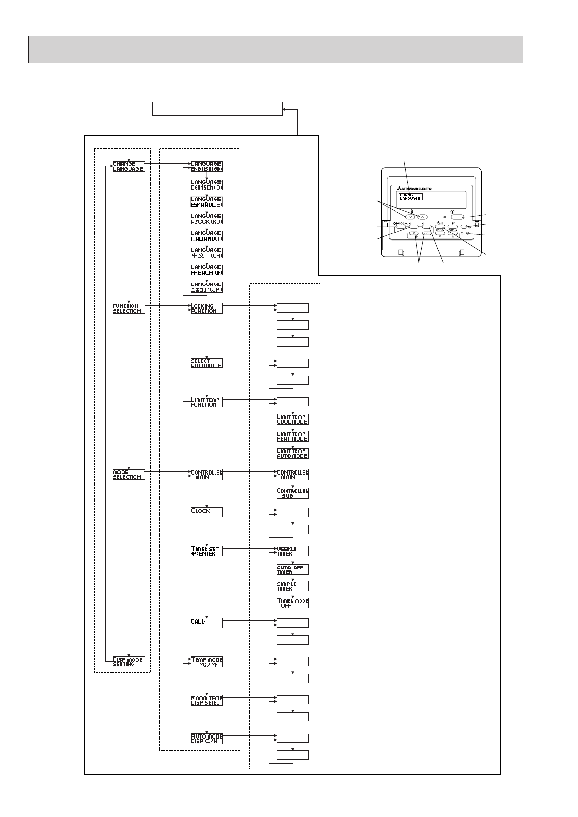
56
Flowchart of Function Setting
Setting language (English)
Item1 Item2
Change
Language
Normal display
(Display when the air condition is not running)
Hold down the E button and press the D button for 2 seconds.
Remote controller function selection mode
E
Hold down the E button and press the D button for 2 seconds.
E Press the operation mode button.
G Press the TIMER MENU button.
D Press the TIMER ON/OFF button.
G
EN
Dot display
GE
ES
RU
G
IT
ZH
FR
F
TEMP.
MENU
E
PAR-21MAA
G
MONITOR/SET
BACK DAY
CLOCK
ON/OFF
OPERATION
ON/OFF
FILTER
CHECK
CLEAR
I
A
TEST
B
H
D
C
Function
selection
Mode
selection
JA
G
G
E
G
G
E
G
G
E
G
G
G
D
D
D
D
D
D
Item3
D
D
D
D
D
D
OFF
on1
on2
ON
OFF
OFF
Operation lock setting is not used.
(Initial setting value)
D
Operation lock setting is except On/Off buttons.
Operation lock setting is All buttons.
The automatic mode is displayed when the operation mode is
selected. (Initial setting value)
D
The automatic mode is not displayed when the operation mode
is selected.
The temperature range limit is not active. (Initial setting value)
D
The temperature range can be changed on cooling/dry mode.
The temperature range can be changed on heating mode.
The temperature range can be changed on automatic mode.
The remote controller will be the main controller. (Initial setting value)
D
The remote controller will be the sub controller.
ON
OFF
The clock function can be used. (Initial setting value)
D
The clock function can not be used.
Weekly timer can be used. (Initial setting value)
D
Auto off timer can be used.
Simple timer can be used.
Display
mode setting
Timer mode can not be used.
D
OFF
D
CALL-
G
G
G
G
D
:
°F
D
D
ON
OFF
D
D
ON
OFF
D
The set contact numbers are not displayed in case of error.
(Initial setting value)
D
The set contact numbers are displayed in case of error.
:
The temperature unit
D
The temperature unit °F is used.
Room air temperature is displayed. (Initial setting value)
is used. (Initial setting value)
D
Room air temperature is not displayed.
One of "Automatic cooling" and "Automatic heating" is displayed
under the automatic mode is running. (Initial setting value)
D
Only "Automatic" is displayed under the automatic mode.
Page 57

57
SYSTEM CONTROL9
9-1. VARIETY OF SYSTEM CONTROL FUNCTIONS
System Name System Diagram Features
Parts Required in Addition to Standard System
Components (Indoor/Outdoor Units, Remote Controller)
A.Remote control-
ler operation
(Standard)
B.Remote control-
ler operation
Use of two controllers enables
operation of the air
conditioner both
from a distance
and nearby.
C.Group control
operation
Use of one remote
controller to control multiple air
conditioners with
the same settings
simultaneously.
D.Remote/local
combined control
operation
Allows start/stop
of the air conditioner from a distance, and prohibits/permits start/
stop from remote
controllers.
E.Operation by
external signal
F.
Control and remote
display by external
signal (extraction
of monitor signal)
Enables you to
display the operation state and
control start/stop
from a distance.
• There are two types of remote controllers: wired type
and wireless type.
• Simultaneous twin indoor units are started or stopped
simultaneously.
• Up to two remote controllers can be connected to
one group.
• Simultaneous twin units are counted as each unit.
• Operation control by the latest command (last entered priority)
• Wired and wireless remote controllers can be combined as a pair.
• One group can consist of up to 16 indoor units, and
they can be started sequentially by connecting the
remote controller to them and assigning an address
to each inter face.
• Simultaneous twin units are counted as one unit.
• All the units belonging to the same group are operated in the same mode, but thermostats can be
turned ON/OFF individually for each indoor unit.
• Up to two remote controllers can be connected.
• All the air conditioners can be turned ON/OFF collectively
from a distance.
• Operation can be switched between the remote operating panel and local controller.
• Operations (e.g., temperature adjustment, airflow, airflow direction) except for start/stop operations can be
performed even if the remote controller is being operated.
• In the case of simultaneous twin units connect the
controller to one indoor unit only. If connected to two
indoor units, an error (operation stop) may occur.
• Control by an external timer is possible by connecting it.
• Use of optional "remote ON/OFF adapter" enables
remote control via relay. (Level signal)
Extraction of non-voltage contact output
Extraction of DC12 V contact output
* One of the wired remote con-
trollers must be set as a sub
remote controller.
Wired remote controller (additional)
(PAR-21MAA)
Inter face MAC-397IF-E
Remote ON/OFF adapter
(PAC-SE55RA-E)
Relay box
(Part to be provided at your site)
Remote operating panel
(Part to be provided at your site)
Remote ON/OFF adapter
(PAC–SE55RA-E)
Remote operation adapter
(PAC-SF40RM-E)
Remote display panel
(Part to be provided at your site)
Multiple remote controller adapter
(PAC-SA88HA)
Remote display panel
(Part to be provided at your site)
• Use of optional "remote operation adapter" and
"remote display panel" (Part to be provided at your site)
provides non-voltage contact outputs of signals
(operation, error) and operation/stop input function.
• Use of optional
"Multiple remote controller adapter"
and "re
mote display panel" (Part to be provided at
your site)
provides DC12 V contact outputs of signals
(operation, error) and operation/stop input function.
Indoor unit
Outdoor
unit
Remote
Controller
Relay box
Indoor unit
Remote Controller
Remote operating panel
Remote
Controller
Indoor
unit
Remote
Controller
Inter face
Indoor
unit
Outdoor
unit
Adapter
Indoor unit
Remote Controller
Remote display panel
(operation, error)
Page 58

58
Outdoor
unit
Indoor
unit
Sub
Main
Remote
Controller
System Name System Diagram Features
Parts Required in Addition to Standard System
Components (Indoor/Outdoor Units, Remote Controller)
G. Timer operation
Enables control
of start and stop.
* For control by
external timer,
refer to Remote/
handheld combined control operation".
H.Interlock opera-
tion with periph-
eral equipment
Enables control of
Mitsubishi Lossnay
ventilator by remote
controller.
I.Rotation
• Weekly timer:
In addition to ON/OFF, up to eight temperature
patterns can be set for each day of the week.
* Only one timer can be selected; the auto off, simple
and weekly timers cannot be combined.
• Simple timer: Start and stop operations can each be
performed once within 72 hours (can
be set in 1-hour increments).
• Auto off timer: Operation is stopped when the preset
time elapses following the start of
operation.
The time can be set from 30 minutes
to 4 hours in 30-minute increments.
* Only one timer can be selected; the simple and auto
off timers cannot be combined.
• Connecting a Lossnay ventilator and an indoor unit
enables control of interlock/solo ventilation operation and airflow.
(Only the microcomputer type Lossnay ventilator
can be used.)
•
•
MA Remote controller
(PAR-21MAA)
When abnormality occurs while operating, it changes
into operating the back up unit, and operating is
continued.
(Unit function Mode No. 20 setting No.3 , Indoor
controller board SW-5-4 ON)
Main / Sub setting
Main : Indoor controller board
SW5-3 : OFF
Sub : Indoor controller board
SW5-3 : ON
Each system operates alternately for 24 hours or 168
hours.
(Unit function Mode No. 20 setting No.1: 24 hours/
No.2 : 168 hours, Indoor controller board SW 5-4 ON)
Main / Sub setting
Main : Indoor controller board
SW5-3 : OFF
Sub : Indoor controller board
SW5-3 : ON
This system can correspond only by
the pattern of two refrigerant group
by 1 : 1 (indoor and outdoor unit
combination) systems.
Lossnay
ventilator
Indoor unit
Remote
Controller
Page 59

59
9-2. ONE REMOTE CONTROLLER (STANDARD) OPERATION
(1) One Wired Remote Controller
(OC: Outdoor unit IC: Indoor unit R: Remote controller (for wireless type: optical receiver adapter)
Slim Air Conditioners System
Remote controller
connection circuit
(Controller cable)
Outdoor unit
OC
Indoor unit
IC
Wired
remote
controller R
Indoor/Outdoor
connection
cable
Remote
controller
cable
OC
IC-1RIC-2
2
2
OC
IC-1
R
2
2
Standard 1:1 Simultaneous Twin Indoor controller board switch setting
SW5-3
OFF
ON
Indoor unit IC
IC-1 (Main)
IC-2 (Sub)
(Reference)
1 If simultaneous twin, connect the remote controller to an indoor unit. All functions of the indoor unit can be controlled
even if different models (different types) are mixed. Note that there may be some restrictions of the functions.
2 Electrical wiring diagram
OC IC
1
2
LN
Power source wiring
1
2
1
2
1
2
R
(No polarity)
Outdoor unit Indoor unit Remote controller
Power
source
wiring
(Polarity)
• Power supply terminal block L, N
• Indoor/outdoor connection cable terminal
block 1,2 (Polarity)
• Remote controller cable terminal block
1,2 (No polarity)
(2) Wireless remote controller
Slim Air Conditioners System
Remote controller
optical receiver
section connection
circuit
Outdoor unit
OC
Indoor unit
IC
Wireless
remote controller
receiver section R'
Indoor/Outdoor
connection
cable
Wireless remote
cont roller cable
Wireless
remote
cont roller
cable
Remote
cont roller
cable
OC
IC-1
R'
IC-2
2
2
9
OC
IC-1
R'
2
9
Standard 1:1 Simultaneous Twin Indoor controller board switch setting
SW5-3
OFF
ON
Indoor unit IC
IC-1 (Main)
IC-2 (Sub)
(Reference)
1 If simultaneous twin, connect the remote controller to an indoor unit. All functions of the indoor unit can be controlled
even if different models (different types) are mixed. Note that there may be some restrictions of the functions.
2 Electrical wiring diagram
CN90
Controller board
Indoor unit IC
9
CNB
12
Wireless remote controller
optical receiver section R’
Remote controller
cable terminal block
Page 60
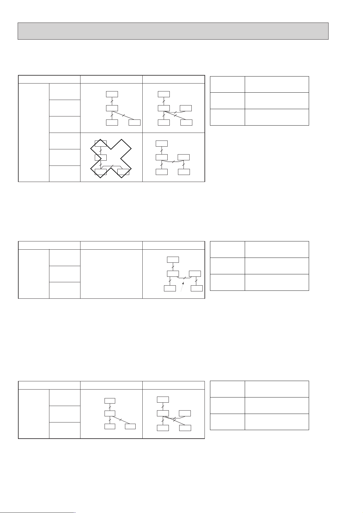
60
9-3. TWO-REMOTE CONTROLLER OPERATION
(1) Two Wired Remote Controllers
(R: Wired remote controller)
Slim Air Conditioner System
Standard 1:1 Simultaneous Twin
[Reference]
1 In the case of free component multi type systems consisting of simultaneous twin units, connect the remote controllers to each indoor unit.
All the functions of the connected indoor units can be controlled even if the system consists of different models. However, some function may be
restricted.
2 In the case of free component multi type systems consisting of simultaneous twin units, the indoor units should be connected by crossover wiring.
3 Set one of the remote controllers as the main controller (factory setting) and the other as the sub controller using the remote controller's function
selection.
(2) Two Wireless Remote Controllers
Slim Air Conditioner System
Standard 1:1 Simultaneous Twin
Remote
controller
connection
circuit
(Controller
cable)
Outdoor unit
OC
Indoor unit IC
Wired remote
controller R
Outdoor unit
OC
Indoor unit IC
Wired remote
controller R
OC
2
2
IC-1
IC-2
R-1
R-2
2
2
2
OC
2
IC
R-1
R-2
2
OC
2
IC-1
IC-2
R-1
R-2
2
2
Remote
controller
receiver
connection
circuit
Outdoor unit
OC
Indoor unit IC
Wireless remote
controller receiver section R'
—
* Numbers given in ( ) apply when power is supplied to the indoor and outdoor units separately.
[Reference]
1 In the case of free component multi type systems consisting of simultaneous twin units, connect two wireless remote controller receivers
(one each) to any two of the indoor units. All the functions of the connected indoor units can be controlled even if the system consists of different
models. However, some functions may be restricted.
2 In the case of free component multi type systems consisting of simultaneous twin units, the indoor units should be connected by crossover wiring.
In the case of "standard 1:1" connection, it is not possible to connect two remote controller receivers to the indoor units. However, with systems
3
consisting of simultaneous twin units, it is possible to connect a remote controller receiver to two indoor units. In this case, all the pair numbers
will be "0" (factory setting, no change necessary), and all the units will be turned ON/OFF simultaneously.
4 When using two or more wireless remote controllers, the display contents on the remote controllers may differ from the actual settings, since the
operation made last by any of the remote controllers will be effective.
(3) One Wired and One Wireless Remote Controller
(R: Wired remote controller, R': Wireless remote controller receiver)
Slim Air Conditioner System
Standard 1:1 Simultaneous Twin
Remote
controller
receiver
connection
circuit
Outdoor unit
OC
Indoor unit IC
•Wired remote
controller R
•Receiver R'
OC
2
2
IC-1
IC-2
R
R'
9
[Reference]
1
In the case of free component multi type systems consisting of simultaneous twin units, connect both the wired remote controller and wireless
remote controller receiver to any one of the indoor units. All the functions of the connected indoor units can be controlled even if the system
consists of different models. However, some functions may be restricted.
2
In the case of free component multi type systems consisting of simultaneous twin units, the indoor units should be connected by crossover wiring.
3
When using two or more wireless remote controllers, the display contents on the remote controllers may differ from the actual settings, since the
operation made last by any of the wireless remote controllers will be effective.
(R': Wireless remote controller receiver)
2
2
2
Remote controller cable
Indoor controller board switch setting
SW5-3
OFF
ON
Indoor unit IC
IC-1 (Main)
IC-2 (Sub)
Indoor controller board switch setting
SW5-3
OFF
ON
Indoor unit IC
IC-1 (Main)
IC-2 (Sub)
Indoor controller board switch setting
SW5-3
OFF
ON
Indoor unit IC
IC-1 (Main)
IC-2 (Sub)
Remote
controller
cable
OC
2
IC
2
R-1
Indoor/outdoor
connection cable
R-2
2
Indoor/outdoor
connection cable
Receiver
connection
cable
OC
2
IC-1
9 9
R'-1
IC-2
R'-2
Indoor/outdoor
connection cable
Remote
controller
cable
OC
3(2)
IC
Receiver
connection
9
2
cable
R
R'
Page 61

61
Indoor control board
CN105
or
CN92
2.Connecting the remote control interface with each system
(For details on each system, see the relevant instruction manual.)
• Replace the interface unit mounting cord clamp with a supplied mounting cord clamp based on the thickness of the
connecting cable used for each system.
• The cables connected to the Indoor unit should be mounted on or near the Indoor unit.
If the connecting cable is not securely mounted, the connector may detach, break, or malfunction.
• Set the interface dip switch (SW500–502) settings before turning on the power.
• If the interface dip switch (SW500–502) settings are not set correctly, the system will not function properly.
Connecting cable for each system
Mounting screws 4 o 16
Electrical wire mounting
bracket
Mounting cord clamp
Mounting screws 4 o 10
Mounting cord clamp
Connect the connecting cable that comes with the
interface unit to the connector
CN105 or CN92 on the indoor control board.
INDOOR
Mounting screws (black) 3.5 o 12
Interface unit mounting cord clamp or mounting
cord clamps
9-4. GROUP CONTROL OPERATION
(COLLECTIVE OPERATION AND CONTROL OF MULTIPLE REFRIGERANT SYSTEMS (2 to 16))
●
●
●
●
Group control can be operated by using MAC-397IF-E.
The setting of wired remote controller is subjected to variation according to the function of the indoor unit.
(for mode operation, setting temperature, fan step, air direction)
The display of remote controller and operating the indoor unit might be different.
Neither the test run nor the function setting can be done by MA remote controller connected with MAC-397IF-E.
1.Connecting the MA& CONTACT TERMINAL Interface to the Indoor Unit
• Connect the interface unit and the indoor control board using the connecting cable that came with the interface.
• Extending or shortening the connecting cable that comes out of the interface may cause it to malfunction. Also,
keep the connecting cable as far as possible away from the electrical wires and ground wire. Do not bundle them together.
Page 62

62
Use as a Wired Remote Control (Using the MA Remote Controller)
Note:
1.Be sure the Auto Heating/Cooling Display Setting on the MA remote controller is set to OFF before use.
• For information on how to set the Auto/Heating Cooling Display Setting, see the MA remote controller
instruction manual.
• The actual operating status of the unit may differ from what is shown on the remote controller display
2.A test run cannot be initiated using the test run switch on the MA remote controller..
3.The horizontal vanes on the unit cannot be operated using the louver switch.
4.The range of room temperature indication is between 10: and 38:.
CN560
TB580
2
1
2
A
B
Indoor unit
Remote control cord that came with
the MA remote controller (Non polarity)
Dip switch settings
SW500 does not have to be set.
SW501:
SW501- No. 1-4: Refrigerant address
Set this switch when multiple indoor units (and remote control interfaces) are connected to a single MA remote controller.
Always start the refrigerant address at "0".
1
Even when connecting multiple outdoor units, set a different refrigerant address for each indoor unit.
ON
1
2 3 4
ON
1
2 3 4
ON
1
2 3 4
ON
1
2 3 4
1Outdoor unit
2Outdoor unit
3Indoor unit
4Interface
5MA remote controller
Refrigerant
address
0
1
2
15
SW501- No. 5–6
ON
5
6
When the model of Mr. SLIM exists in the same group, it sets it to turning ON.
Set them to ON only when using the room temperature sensor installed in the MA remote controller.
* This can be switched when an accurate room temperature cannot be detected by the air conditioner unit.
PE-EAK series do not have a room temperature sensor on their MA remote controllers.
No. 5 should normally be set to OFF.
Under the following conditions, No.6 should normally be set to ON.
Interface unit
Refrigerant
address "0"
Refrigerant
address "1"
Refrigerant
address "2"
MA remote controller
(PAR-21MAA)
* PAR-20MAA cannot be used
with this interface.
112
3333
4
5
44
Page 63

63
SW501: Settings to accommodate MA remote controller and settings to accommodate outdoor units
SW No.
No. 1
No. 2
No. 3
No. 4
Functions OFF ON Comments
Only specify these settings when connecting an
MA remote controller.
Functions
Room temperature detector
The model of Mr. SLIM exists in the
same group.
This should normally be set to ON.
ON
1
2 3 4 5 6
ON
1 2 3 4 5 6
ON
1
2 3 4 5 6
ON
1
2 3 4 5 6
ON
1 2 3 4 5 6
ON
1
2 3 4 5 6
ON
1
2 3 4 5 6
ON
1 2 3 4 5 6
ON
1 2 3 4 5 6
ON
1
2 3 4 5 6
ON
1
2 3 4 5 6
ON
1
2 3 4 5 6
ON
1
2 3 4 5 6
ON
1
2 3 4 5 6
ON
1 2 3 4 5 6
ON
1
2 3 4 5 6
Refrigerant address 0
Refrigerant address 1
Refrigerant address 2
Refrigerant address 3
Refrigerant address 4
Refrigerant address 5
Refrigerant address 6
Refrigerant address 7
Refrigerant address 8
Refrigerant address 9
Refrigerant address 10
Refrigerant address 11
Refrigerant address 12
Refrigerant address 13
Refrigerant address 14
Refrigerant address 15
OFF
Indoor unit
Not mixed
ON
Remote control
Mixed
Comments
This should normally be set to OFF.
SW No.
No. 5
No. 6
Page 64

64
* Fan speed 2 step model : An actual fan speed is 2 step though the display of remote controller becomes 4 step or 3 step.
3. Test Run (Check Operations)
Interface status monitor
You can check the status of the interface by the LED lamp on the interface unit board.
LED lamp no.
LED521
LED522
LED523
Lamp off
DC 12 V is not being supplied from the
air conditioner.
Device is not communicating properly
with the air conditioner.
Device is not communicating properly
with the MA remote controller.
Lamp on
DC 12 V is being supplied from the air
conditioner.
–
–
Blinking
–
Blinking at approx. 1 second intervals: Device is
communicating normally with the air conditioner.
Blinking at approx. 8 second intervals: Device is communicating normally with the MA remote controller.
* Use the table above to check the device operations.
SW502 : Air Conditioner Function Settings
SW No.
No. 1
No. 2
No. 3
No. 4
No. 5
No. 6
No. 7
No. 8
Functions
Cooling only type/ Heat pump type
Auto mode
Fan speed
Vane
Swing
Not in use
Fan mode
OFF
Heat pump type
Not available
(setting No.3 disabled)
Available
(unit)
Available
Available
–
Not available
ON
Cooling only type
Available
(setting No.3 enabled)
Available
(remote controller)
Not available
Not available
–
Available
Comments
Set to OFF.
Permanently set to OFF.
4 speeds
3 speeds (2-speed
model set ON)
When operating a 2-speed model with the 3-speed
setting (ON), the MA remote controller display will
indicate 3 fan speeds.
The table below shows the displays and the actual
outputs at that time.
Display Meaning Indoor unit output
Low speedLow speed
Medium speed High speed
High speed
Set the mode in accordance with the operation
manual for the indoor unit.
Heat pump type : Set to ON.
Cooling only type : Set to OFF.
The Vane function of either of indoor unit :
When the function is provided, it is Available (OFF).
When the function is not provided, it is Not available (ON).
The Swing function of either of indoor unit :
When the function is provided, it is Available (OFF).
When the function is not provided, it is Not available (ON).
Set to ON.
High speed
4. Mounting the Remote Control Interface Unit
The Interface unit should be placed in a location where the connecting cable from the interface can reach an indoor unit.
The device will not function properly if the connecting cable is extended so the connecting cable should not be extended.
Mount the interface unit securely to a pillar or wall using 2 or more screws.
■ When Using Wall Mounting Brackets
1
Attach the wall mounting brackets to the interface unit
using 2 mounting screws.
2
Mount the unit to a pillar or wall using 2 mounting screws.
Interface unit
Wall mounting
brackets
Mounting screws
Mounting screws
Mounting screws
Cord clamp for
wiring
Page 65

65
■ When Mounting Directly to a Wall
Mount the interface unit case to the wall using the mounting
screws.
Interface case
mounting screws
Mounting
screws
When mounting the interface unit inside a ceiling
or wall, install an access door to facilitate maintenance.
When the interface unit is mounted
above an indoor unit, it should be
positioned 40 mm or more away from the
unit to ensure that ceiling grills can be
removed.
40 mm or more
Attach the interface unit connecting cable here.
Store extra connecting cable in the ductwork space
behind the indoor unit.
* If there is any slack in the connecting cable, use a
fastener to keep it in place.
* When mounting the interface unit using a cushioning
material , be sure to mount it in a location where it will not
fall.
Interface unit
Cushioning material
Page 66
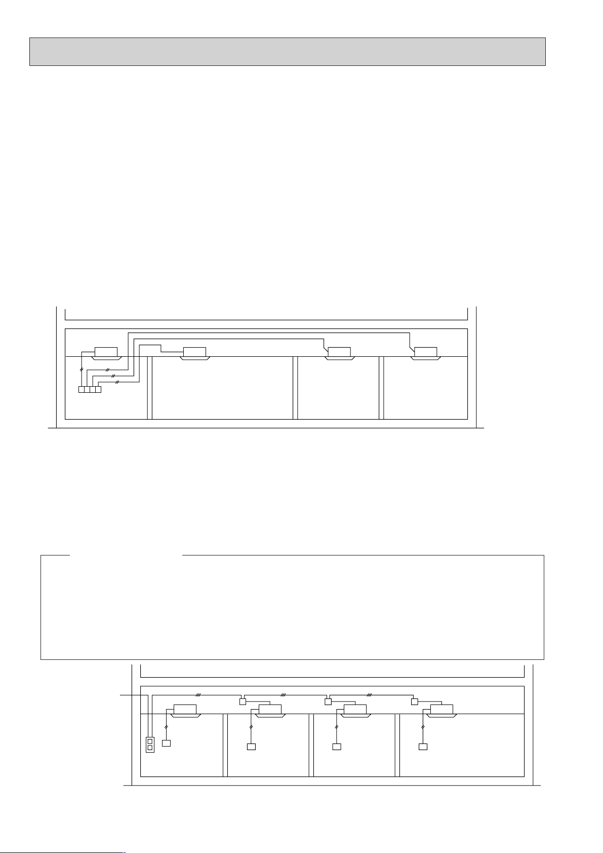
66
9-5. POWER OUTAGE AUTOMATIC RECOVERY OPERATION
• Whenever a power outage or switching of the power supply causes the power supply of an operating air conditioner to go
from OFF to ON, this function will automatically restore the operation of the air conditioner to its previous operating mode.
w If the power is turned from OFF to ON when the air conditioner is not in operation, the air conditioner will not automatically
be turned on. However, the timer operation will be cancelled if the air conditioner is in timer operation (including when the
unit is waiting for its start time). Setting for timer operation must be performed once again.
• If there is a momentary power outage of less than one second while the air conditioner is in operation, there may not be a
clear determination of whether or not there was a power failure. When it has been determined that there has been a power
failure, recovery will take approximately four minutes after the power is restored. Please wait. (Once "PLEASE WAIT" has
appeared on the display, a protection system will operate to prevent the unit from restarting for three minutes.)
When it has been determined that there has been no power failure, operation will continue as is.
• Settings can be made by function selections from the remote controller.
• When there is group control, selection of all refrigerants is required.
9-6. INDIVIDUAL CONTROL OPERATION FROM A SEPARATE ROOM
• By simply centralizing the remote controllers installed in each room in a separate control room, individual control or centralized monitoring of the air conditioners in each room can be attained.
• Air conditioner control can be performed up to a total of 500 meters away by connecting the indoor units and remote controllers with 0.3 to 1.25 mm
2
2-core cable.
• If a remote controller is installed in a room and control room, refer to the section on operating with two remote controllers.
Indoor unit Indoor unit Indoor unit
Remote controller
Control room room 1 room 2 room 3
9-7. COMBINED REMOTE/LOCAL CONTROL
• Operation/remote controller prohibit/ stop can be controlled from a remote location by routing the remote stop/start adapter
(PAC-SE55RA-E sold separately) through the relay box installed on site. When this remote control is cancelled, the local
remote controller can be used for operating and stopping the air conditioner.
1. Basic system wiring
• Use the remote start/stop adapter (PAC-SE55RA-E) and connect the "Start/Stop Circuit From Remote Location" that comes
from the relay box and remote/local selection switch and connect it to the CN32 connector on the printed circuit board for
the indoor unit
W The AC for the control room is usually disconnected from the remote/local control system.
Indoor unit
Relay box Relay box Relay box
Indoor unit
Control circuit
power supply
Indoor unit Indoor unit
Remote
controller
Remote/local
selection switch
Control room W
room 1 room 2 room 3
Remote
controller
Remote
controller
Remote
controller
1 Match the rated power supply voltage of the remote/local selection switch and relay (X2) with the power supply for the con-
troller.
2 When performing group control of multiple outdoor unit using a timer, be sure to arrange the timer so that all units do not start
at the same time. If this is not performed, all of the units will start at one time creating an over current that will cause the circuit
breaker to operate.
3 An on-delay system is one that includes specifications for operating a limited time when an on signal is received and has a tem-
porary off timer for recovery operations.
4 Use a connecting relay when the wiring length exceeds 10 meters, such as when performing remote wiring. If this is not provid-
ed, abnormal operation will occur.
<Points of precaution>
(1) System diagram
Page 67

67
Note: When using group address, connect to refrigerant
address "0" on the inside.
Control circuit
power supply
Dedicated short
circuit prevention
device
Remote/Local
selection switch
No.1 unit
relay box
No.2 unit
relay box
3 Relay box
2
Adapter for
remote start/stop
1
Remote/Local
selection switch
T Timer
(On delay system)
X Relay
Model
PAC-SE55RA-E
(Sold separately)
(Example)
Single polarity
single-throw switch
(125V rating)
To
next
unit
T
Brown
Red
X
2 X2
T
One method of easily
distinguishing the on/off
status of SW1 and SW2
is to use together with a
"illuminated switch R" or
pilot lamp.
T
X
2
SW1
SW2
T
X
2
Orange Orange
Brown
Red
•
Starting/stopping
with remote
controller disabled.
• Starting/stopping by
remote operation
enabled.
•
Starting/stopping
with remote
controller disabled.
• AC is in operation.
• Starting/stopping by
remote operation
enabled.
•
Starting/stopping
with remote
controller disabled.
• Starting/stopping by
remote operation
enabled.
•
Starting/stopping
with remote
controller disabled.
• AC is in operation.
• Starting/stopping by
remote operation
enabled.
Remote
control
OFFON
Description of
functions
OFFON
SW1
SW2
OFFON
Remote/Local
selection switch
(2) Basic wiring diagram
(3) Part specifications
2. Examples of system applications
In any of the following examples, there is a five to six second delay from the time the operating command is issued until the
operation begins.
1 This is when starting and stopping is performed by remote operation or external timer and when starting and stopping by
the remote controller is to be prohibited.
Indoor unit
circuit board
CN32
Orange
Red
Brown
On site wiring On site wiring
On site wiring
Timer
Timer
For remote operation
On site wiring
On site wiring
This is not used.
Protect exposed wire by
wrapping with insulating tape
On site wiring
SW1
Indoor unit
circuit board
CN32
Orange
Red
Brown
SW1
SW2
Indoor unit
circuit board
CN32
Orange
Red
Brown
SW2
Indoor unit
circuit board
CN32
Orange
Red
Brown
SW2
Indoor unit
circuit board
CN32
Orange
Red
Brown
Indoor unit
circuit board
CN32
Orange
Red
Brown
SW2
For remote operation
For timer operation
2 This is when starting and stopping is performed by remote operation or external timer and when starting and stopping by
the remote controller is to be separated.
3 This is when starting and stopping is performed by remote operation and then allowing starting or stopping by remote con-
trol at any time.
4 This is when permitting or prohibiting operation by remote controller is performed by external circuit.
If SW2 is on, operation by remote controller cannot be
performed.
If SW2 is off, operation by remote controller is permitted.
Use momentary switch for SW2. (Manual operation/automatic recover switch on
time is more than one second.)
Press SW2 (on time is more than one second) and operation starts. After this has
been done, stopping or restarting can be down by remote controller.
Page 68

68
9-8. OBTAINING REMOTE DISPLAY
Use the remote operation adapter (PAC-SF40RM-E) to provide operation/error non-voltage contact output and on/off input
function.
(1) Wiring method
CN90 CN1
CN41
Wireless
3
TB3
External input
TB2
Error
TB1
Operation
2
Indoor control circuit board Remote operation adapter
5
External input
Error output
(No voltage momentary "a" contact)
Operating output
(No voltage momentary "a" contact)
No voltage
(Momentary "a" contact)
HA
..
Caution
TB3 is a dedicated terminal for contact point input. Never input voltage. It will damage
the indoor control circuit board.
<Connections on the indoor unit side>
1 When using external output function
Insert the 9-prong connector (3-core) of the attached cable to CN90 on the indoor control circuit board.
2 When using the external input function
Insert the 4-prong connector (2-core) of the attached cable to CN41 on the indoor control circuit board.
W The connector is direction-sensitive. Use care not to make an error when inserting.
Never force the connectors. This will result in damage.
(2) Locally procured parts
Item Name Model and specifications
External output function External output signal wire Use sheathed vinyl coated cord or cable.
Wire type: CV, CVS or equivalent.
Wire size: Stranded wire 0.5mm2to 1.25mm
2
Single straged: {0.65mm to 1.25mm
Display lamp, etc. No voltage “a” contact AC200V (DC30V), 1A or less
External input function External input signal wire Use sheathed vinyl coated cord or cable.
Wire type: CV, CVS or equivalent.
Wire size: Stranded wire 0.5mm
2
to 1.25mm
2
Single straged: {0.65mm to 1.2mm
Switch No voltage “a” contact
(Start and stop operation is switched by inputting a
pulse of 200ms or more)
9-9. TIMER OPERATION
● Timer operation can be performed by setting the wired or wireless remote controller timer. Start and stop times can be set in
10-minute increments within a 24-hour period.
● When used in combination with the central control remote controller of the M-NET control system for the outdoor unit, one
program timer can be used for individual timer settings for each group of the central control system. (Each timer setting can
be stored in data memory so timer settings for up to 50 groups can be set individually.)
W Please refer to the MELANS catalog or technical information for details about the central control remote controller.
1.Operating with on-site timer
(1) Summary of system
If the “Remote ON/OFF adapter” (PACSE55RA-E) (sold separately) is used, the
on-site timer can be operated to turn
each unit on and off.
Power supply for controller
Timer control
panel (on-site)
Remote controller
Indoor unit
Remote controller
Indoor unit
Remote controller
Indoor unit
Page 69

69
(2) Basic pattern for timer control
Use a no-voltage contact point output timer (one that has separate circuits for the load side and timer power supply).
a) Timer-independent control b) Combined control by timer and remote controller
Orange
As selected by remote controller operation switch.
From indoor unit
Red
Brown
T
SW ON
SW OFF
Timer control
Remote controller control
SW
Orange
From indoor unit
Red
Brown
T
(3) Basic system
Refer to 9-7. COMBINED REMOTE/LOCAL CONTROL.
9-10. LINKED OPERATION WITH PERIPHERAL AIR CONDITIONERS EQUIPMENT
■ Lossnay operation
● Linked operation with a Lossnay unit can be obtained by connecting Lossnay linkage cable (Model PAC-SB81VS - sold
separately) to the CN2L (Remote kit) on the circuit board of the indoor unit. This function must be selected from the
remote controller.
1 Summary of wiring
● Connect the Lossnay linkage cable (Model PACSB81VS) connector to CN2L on the indoor unit on
the circuit board of the indoor unit.
● Connect the lead wire of the Lossnay linkage cable to
the Lossnay external control input terminal blocks (1)
and (2).
(At this time, the input terminal blocks (1) and (2)
have no polarity.)
Wiring diagram
Control circuit board
Slim indoor unit
Lossnay
Lossnay linkage
(PAC-SB81VS)
External control
input terminal
block
1
2
3
Connector
(CN2L)
2 Precautions when wiring
● The Lossnay linkage cable can be extended up to a maximum of 500 meters.
When extending the Lossnay linkage cable, be sure to connect securely and take proper steps to ensure insulation.
(Extension cable specifications: Sheathed vinyl cord or cable 0.5 to 0.75mm
2
)
● Lossnay linked cable
● Arrange wiring so that there can be no contact between the Lossnay linkage cable and the power supply cord. Contact
may cause malfunctioning. (Separate by 5cm or more.)
9-11. OBTAINING HUMIDIFIER SIGNAL
● The humidifier signal that is linked to the AC heating operation (indoor unit ventilator) can be obtained by connecting the
adapter for the humidifier signal to connector CN25 on the printed circuit for the indoor unit and wiring it to the humidifier
unit via the on-site relay box. There is no output when the thermostat is off, during heating preparation and during defrosting.
Basic wiring
X: Relay
(DC12V) CN25 (Indoor unit circuit board)
System example
Remote controller
Indoor unit
Relay box
(On-site tinstallation)
Relay box
(On-site tinstallation)
Remote controller
Humidifier unit
Humidifier
unit
W Please consult your nearest Mitsubishi Electric
representative for information about obtaining the
adapter for humidifier signal.
9-12. EXTERNAL MOUNTING OF TEMPERATURE SENSOR
● Temperature control from an alternative external location can be performed by connecting the temperature sensor (Model
PA C-SE41TS-E - sold separately) to the CN20 connector on the circuit board for the indoor unit.
● The wired remote controller also has an internal temperature sensor. Function selection from the remote controller is
required.
Refer to “FUNCTION SETTING” for information of installation manual about selecting functions with the remote controller.
Page 70

70
9-13. MULTIPLE REMOTE CONTROL DISPLAY
You can control several units with a multiple remote control display, by
wiring an optional multiple remote controller adapter (PAC-SA88HA-E) with
relays and lamps on the market.
How to wire
(1) Connect the multiple remote controller adapter to the connector CN51
on the indoor controller board.
(2) Wire three of the five wires from the multiple remote controller adapter
as shown in the figure below.
[Notes on Signs]
X1:Relay (for operation lamp)
X2:Relay (for check lamp)
RL:Operation Lamp
GL:Check Lamp
CN51
connector(5P)
GREEN
Power
supply
Electrical insulation is needed.
Wiring at the actual place
Optional multiple remote
controller adapter
The maximum distance between
indoor board and relay is 10m.
YELLOW
ORANGE
RED
BROWN
5
X2
X2
GL
RL
X1
X1
1
<Wiring >
Power
supply
Remote
controller
cable
Relay box
(Field supply)
Remote
controller
Remote
controller
Remote
controller
3wires
3wires
3wires
2wires
No.1 unit No.2 unit No.3 unit
Muitiple remote control
ON-OFF display
(Field supply)
(Operation check)
<System>
Power
supply
RL-1
GL-1
Multiple Remote Control Display
Multiple remote
controller adapter
connect to
the connector CN51
Relay box
5
X1-1
X2-1
1
<Wiring diagram>
RL-2
GL-2
RL-3
No.1 unit
GL-3
X1-1
X2-1
X1-2
X1-3
X2-3
X2-2
5
1
No.2 unit
5
1
No.3 unit
X1-2
X2-2
X1-3
X2-3
Refer to 7-7-2. Indoor
controller board.
●Whenever the indoor unit is operating, the
duct fan operates.
(1)Connect the optional multiple remote
controller adapter(PAC-SA88HA-E)to
the connector CN51 on the indoor controller board.
(2)Drive the relay after connecting the 12V
DC relay between the Yellow and
Orange connector lines.
Use a relay under 1W.
MB: Electromagnetic switch power relay
for duct fan.
X: Auxiliary relay (12V DC LY-1F)
Be sure to secure insulation
material by tape and such
5
Green
Yellow
Orange
Connector (5P)
Indoor unit side
Multiple remote
controller adapter
PAC-SA88HA-E
Be sure to secure insulation
material by tape and such
Installation at site
CN51
on
indoor
controller
board
Red
Brown
1
~
MB
9-14. INTERLOCKING OPERATION METHOD WITH DUCT FAN (Booster fan)
Page 71

71
DISASSEMBLY PROCEDURE10
Figure1.
Disconnect the fan motor connecter
(and the booster heater connector)
Drain pan
catches (Hidden)
Drain pan
catches (Hidden)
Filter
Bottom plate
Drain pan
Heat exchanger
Bottom plate
assembly
1
2
A
1. Removing the fan motor
1. Remove the 9 screws that fix the bottom plate A,
and remove it.
2. Removing the drain pan as follows:
(1) Remove the screw that fix the drain pan.
(2) Slide the drain pan in the direction
1, Figure1
and unhook the drain pan catch near the drain
pipe.
(3) Slide the drain pan in the direction
2, Figure1
and unhook the 2 catches on the other side of
the drain pipe.
3. Remove the 8 screws that fix the bottom plate
assembly, and remove it.
4. Disconnect the fan motor connector from the con-
troller box.
5. Remove the fan base plate as follow:
Figure2.
(1) Remove the 4 screws1
(2) Slide down the fan base plate to remove.
6. Remove the sirocco fan setting screw and the
motor fixture setting screw to remove the motor
fixture.
Remove the other motor fixture as well, and then
remove the fan motor. (Figure 3)
1
1
Fan base
Page 72

72
Figure3.
Fan base
Sirocco fan
Motor
Housing
assembly
Piece
Bush
Piece
Motor base
(Only PE(H)D-3EAK(H))
Leg
Bush
Sirocco fan
Housing assembly
Page 73

No. Part No. Part Name Drawing No.
Qt’y/set
RoHS COMPLIANT
PEHD-
1.6EAKH
PEHD2EAKH
PEHD-
2.5EAKH
PED2EAK
PED-
2.5EAK
1
2
3
4
5
6
7
8
9
10
11
12
13
S70 031 669G
S70 011 669G
S70 081 669G
S70 091 669G
S70 017 480G
S70 018 480G
S70 019 480G
S70 011 480G
S70 012 480G
S70 011 529G
S70 021 529G
S70 021 500G
S70 031 500G
WW638939Z04
WW638917Z04
WW638940G03
WW638918G03
WW268511G01
WW268511G02
WW268511G03
WW268513G01
WW268513G02
WW638942G01
WW638920G01
WW645496G02
WW645496G03
<G>
<G>
<G>
<G>
<G>
<G>
<G>
<G>
<G>
<G>
<G>
<G>
RO
RO
<X>
1
1
1
1
1
1
1
1
1
1
1
1
1
1
1
1
1
1
1
1
1
1
1
1
1
Bottom Plate Assy 1
Bottom Plate Assy 1
Bottom Plate Assy 2
Bottom Plate Assy 2
Heat Exchanger
Heat Exchanger
Heat Exchanger
Heat Exchanger
Heat Exchanger
Drain Pan Assy
Drain Pan Assy
Filter
Filter
<G> : Compliant
RO : RoHS compliant
NG : Non-compliant
ND : No details
OD : Compliant (No details)
12.13
1.2
10.11
3.4
5.6.7.8.9
73
RoHS PARTS LIST11
PE(H)D-1.6~2.5EAK(H)
EXTERNAL PARTS
Page 74
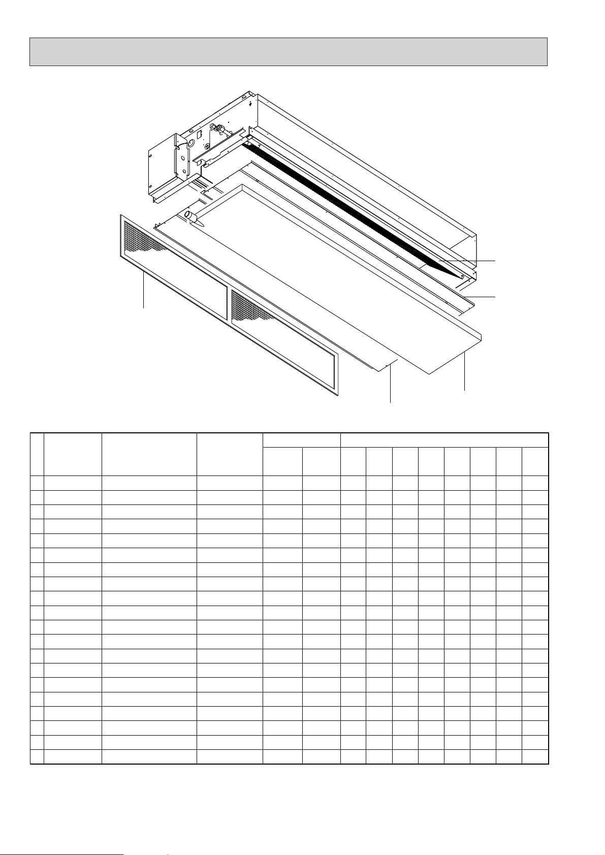
No. Part No. Part Name Drawing No.
Qt’y/set
RoHS COMPLIANT
<G>
<G>
<G>
<G>
<G>
<G>
<G>
<G>
<G>
<G>
<G>
<G>
<G>
<G>
<G>
<G>
<G>
<G>
RO
RO
RO
<X>
<G> : Compliant
RO : RoHS compliant
NG : Non-compliant
ND : No details
OD : Compliant (No details)
PEHD3EAKH
PED-
6EAK
1
2
3
4
5
6
7
8
9
10
11
12
13
14
15
16
17
18
19
20
S70 041 669G
S70 042 669G
S70 040 669G
S70 051 669G
S70 052 669G
S70 050 669G
S70 014 480G
S70 015 480G
S70 016 480G
S70 013 480G
S70 008 480G
S70 009 480G
S70 010 480G
S70 100 480G
S70 050 529G
S70 060 529G
S70 040 529G
S70 050 500G
S70 040 500G
S70 010 500G
WW634050Z01
WW634028Z01
WW631101Z04
WW634052G01
WW634030G01
WW631188G02
WW267783G01
WW267783G02
WW267783G03
WW264218G02
WW267785G01
WW267785G02
WW267785G03
WW264221G03
WW634056G01
WW634034G01
WW631186G01
WW645497G01
WW645497G02
WW645497G03
1
1
1
1
1
PEHD-
4EAKH
1
1
1
1
1
PED5EAK
1
1
1
1
1
PEHD-
5EAKH
1
1
1
1
1
PED-
4EAK
1
1
1
1
1
PEHD6EAKH
1
1
1
1
1
PED-
3EAK
1
1
1
1
1
1
1
1
1
1
Bottom Plate Assy 1
Bottom Plate Assy 1
Bottom Plate Assy 1
Bottom Plate Assy 2
Bottom Plate Assy 2
Bottom Plate Assy 2
Heat Exchanger
Heat Exchanger
Heat Exchanger
Heat Exchanger
Heat Exchanger
Heat Exchanger
Heat Exchanger
Heat Exchanger
Drain Pan Assy
Drain Pan Assy
Drain Pan Assy
Filter
Filter
Filter
18.19.20
1.2.3
15.16.17
4.5.6
7.8.9.10.11.12.13.14
74
PE(H)D-3~6EAK(H)
EXTERNAL PARTS
Page 75
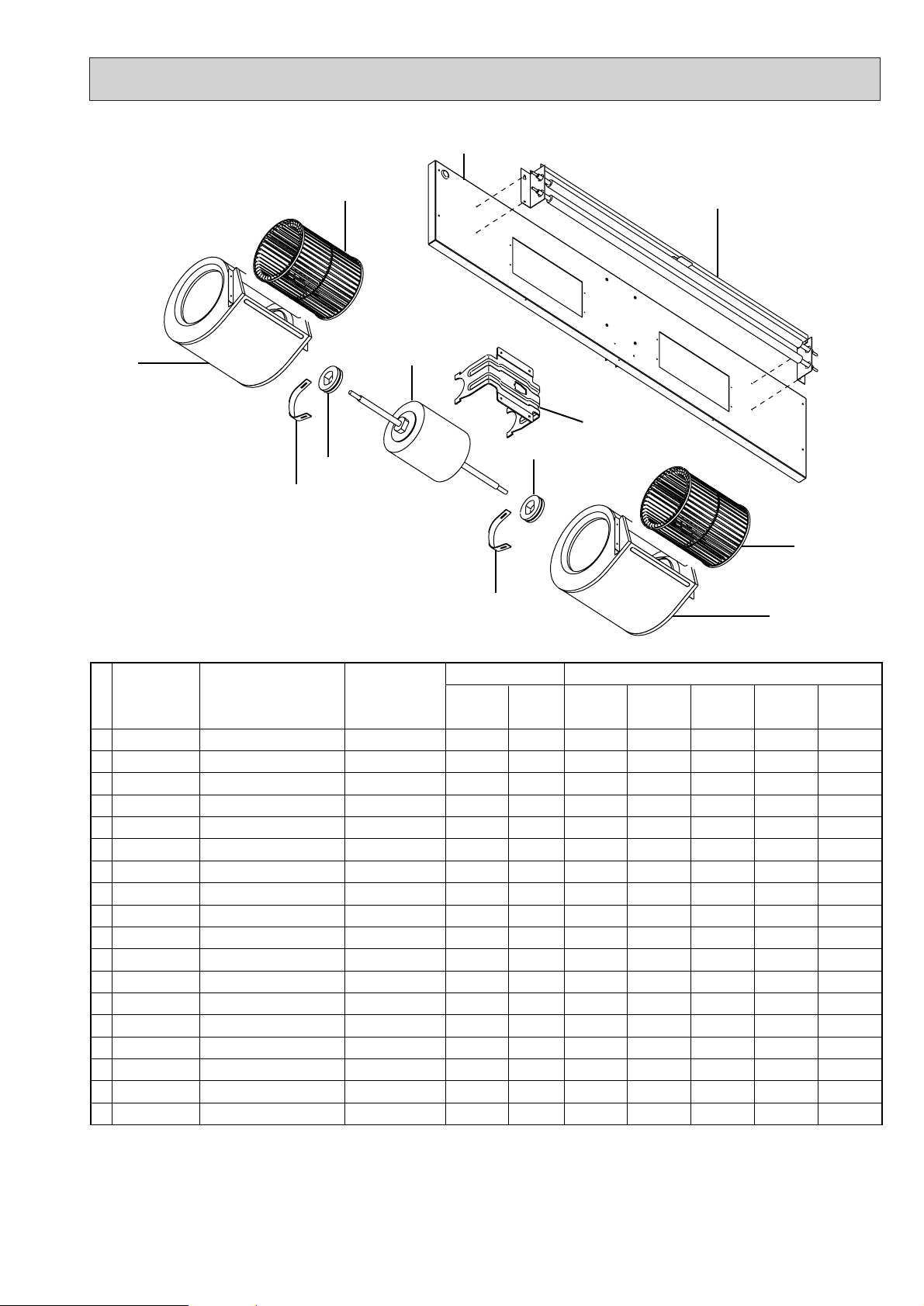
No. Part No. Part Name Drawing No.
Qt’y/set
RoHS COMPLIANT
<G>
<G>
<G>
<G>
<G>
RO
RO
RO
<G>
<G>
RO
RO
RO
RO
RO
OD
RO
RO
RO
<X>
<G> : Compliant
RO : RoHS compliant
NG : Non-compliant
ND : No details
OD : Compliant (No details)
1
2
3
4
5
6
7
8
9
10
11
12
13
14
15
16
17
18
S70 051 677G
S70 061 677G
S70 051 677G
S70 061 677G
S70 922 105
S70 A88 114
S70 A89 114
S70 989 110G
S70 985 110G
S70 Y57 220
S70 Y58 220
S70 Y56 220
S70 Y58 220
S70 Y56 220
S70 652 130
S70 652 131
S70 Y07 300
S70 Y03 300
WW638933Z04
WW638906Z04
WW638933Z05
WW638906Z05
WW818836H01-JP
WW122296G02-JP
WW122297G02-JP
WW638949G03
WW638949G04
WP714315X02-JP
WP714316X02-JP
WP714774X01-JP
WP714316X02-JP
WP714774X01-JP
WW241060H03-JP
WW353715H01-JP
WP493639X02-JP
WP493640X02-JP
Fan Base Assy
Fan Base Assy
Fan Base Assy
Fan Base Assy
Rubber Bush
Sirocco Fan
Sirocco Fan
Fan Casing
Fan Casing
Motor
Motor
Motor
Motor
Motor
Motor Support
Attachment
Heater
Heater
PEHD-
1.6EAKH
PEHD2EAKH
PEHD-
2.5EAKH
PED2EAK
PED-
2.5EAK
1
2
2
2
1
1
2
1
2
2
2
1
1
2
1
1
2
2
2
1
1
2
1
1
2
2
2
1
1
2
1
2
2
2
1
1
2
1
6.7
8.9
16
16
5
5
10.11.12.13.14
15
8.9
6.7
1.2.3.4
17.18
75
PE(H)D-1.6~2.5EAK(H)
BLOWER PARTS
Page 76

No. Part No. Part Name Drawing No.
Qt’y/set
RoHS COMPLIANT
<G>
<G>
<G>
<G>
<G>
<G>
<G>
RO
RO
<G>
<G>
RO
RO
RO
RO
RO
RO
OD
<G>
<G>
RO
<X>
<G> : Compliant
RO : RoHS compliant
NG : Non-compliant
ND : No details
OD : Compliant (No details)
PEHD3EAKH
PED-
6EAK
1
2
3
4
5
6
7
8
9
10
11
12
13
14
15
16
17
18
19
20
S70 073 677G
S70 072 677G
S70 070 677G
S70 073 677G
S70 072 677G
S70 070 677G
S70 922 105
S70 Y01 105
S70 Y07 114G
S70 001 110G
S70 Y15 220
S70 Y16 220
S70 Y17 220
S70 Y15 220
S70 Y16 220
S70 Y17 220
S70 652 130
S70 Y08 130
S70 090 130G
S70 652 131
WW634057Z02
WW634035Z04
WW631118Z10
WW634057Z03
WW634035Z05
WW631118Z11
WW818836H01-JP
WW860050H02-JP
WW631126G02
WW631120G02
WP714964X01-JP
WP714941X01-JP
WP714940X01-JP
WP714964X01-JP
WP714941X01-JP
WP714940X01-JP
WW241060H03-JP
WW631122Z04
WW634069Z02
WW353715H01-JP
1
2
2
2
1
1
PEHD-
4EAKH
1
2
2
2
1
1
PED5EAK
1
2
2
2
1
1
PEHD-
5EAKH
1
2
2
2
1
1
PED4EAK
1
2
2
2
1
1
PEHD6EAKH
1
2
2
2
1
1
PED-
3EAK
1
2
2
2
1
1
1
2
1
2
2
2
1
1
1
2
Fan Base Assy
Fan Base Assy
Fan Base Assy
Fan Base Assy
Fan Base Assy
Fan Base Assy
Rubber Bush
Rubber Bush
Sirocco Fan
Fan Casing
Motor
Motor
Motor
Motor
Motor
Motor
Motor Support
Leg
Motor base
Attachment
9
10
22
21
22
20.21
7.8
7.8
11.12.13.14.15.16
17.18
19
10
9
1.2.3.4.5.6
23.24.25
26.27
76
PE(H)D-3~6EAK(H)
BLOWER PARTS
Page 77

9
10
22
21
22
20.21
7.8
7.8
11.12.13.14.15.16
17.18
19
10
9
1.2.3.4.5.6
23.24.25
26.27
No. Part No. Part Name Drawing No.
Qt’y/set
RoHS COMPLIANT
<G>
RO
RO
RO
RO
RO
<G>
<G>
<X>
<G> : Compliant
RO : RoHS compliant
NG : Non-compliant
ND : No details
OD : Compliant (No details)
PEHD-
3EAKH
PED6EAK
21
22
23
24
25
26
27
S70 508 131
S70 508 132
S70 Y04 300
S70 Y05 300
S70 Y06 300
S70 010 255
S70 020 255
R302K338H02-JP
R302K338G82-JP
WW258903G07-JP
WW258903G08-JP
WW258903G09-JP
WP412172X01
WP412223X01
2
2
1
PEHD4EAKH
2
2
1
1
PED-
5EAK
2
2
1
PEHD5EAKH
2
2
1
1
PED-
4EAK
2
2
1
PEHD6EAKH
2
2
1
1
PED3EAK
1
Attachment
Attachment
Heater
Heater
Heater
Capacitor 6
Capacitor 16
77
PE(H)D-3~6EAK(H)
BLOWER PARTS
Page 78

No. Part No. Part Name Drawing No.
Qt’y/set
No. Part No. Part Name Drawing No.
Qt’y/set
RoHS COMPLIANT
<G>
<G>
OD
OD
<G>
RO
RO
<G>
<G>
<X>
RoHS COMPLIANT
<G>
OD
OD
OD
OD
RO
RO
<X>
<G> : Compliant
RO : RoHS compliant
NG : Non-compliant
ND : No details
OD : Compliant (No details)
*
* : Not illustrated
PEHD6EAKH
1
2
3
4
5
6
7
8
S70 R50 310
S70 K09 313
S70 R20 202
S70 020 202
S70 979 717
S70 435 717
S70 274 215
S70 020 292
RG00N579B43
RG00B435B19
RG71B018H02
RG71J486H12
WP436110X01-JP
BA73S950H02-JP
WP421221X01
RG62C081H01
1
1
1
1
2
1
2
1
PEHD-
1.6EAKH
1
1
1
1
2
1
2
1
PEHD-
3EAKH
1
1
1
1
2
1
2
1
PEHD5EAKH
1
1
1
1
2
1
2
1
PEHD2EAKH
1
1
1
1
2
1
2
1
PEHD-
4EAKH
1
1
1
1
2
1
2
1
PEHD-
2.5EAKH
1
1
1
1
2
1
2
1
Controller Board
Power Board
Thermistor S
Thermistor H
Terminal Block
Terminal Block
Start Relay
Ferrite Core
1
2
3
4
5
6
S70 R50 310
S70 K09 313
S70 R20 202
S70 020 202
S70 979 717
S70 435 717
RG00N579B43
RG00B435B19
RG71B018H02
RG71J486H12
WP436110X01-JP
BA73S950H02-JP
PED-
6EAK
1
1
1
1
2
1
PED-
3EAK
1
1
1
1
2
1
PED2EAK
1
1
1
1
2
1
PED-
5EAK
1
1
1
1
2
1
PED-
2.5EAK
1
1
1
1
2
1
PED-
4EAK
1
1
1
1
2
1
Controller Board
Power Board
Thermistor S
Thermistor H
Terminal Block
Terminal Block
3
4
1
7
5
2
6
78
PE(H)D-1.6~6EAK(H)
CONTROL BOX PARTS
Page 79
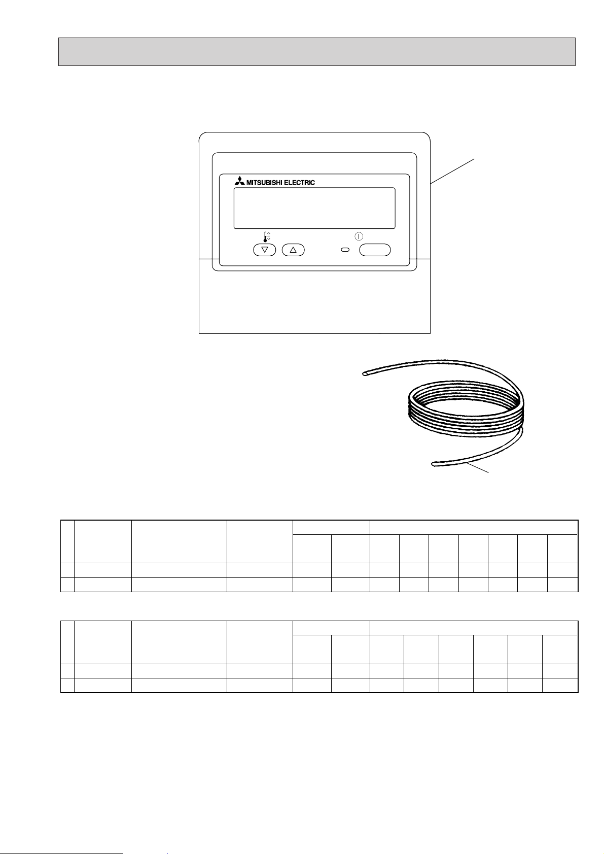
79
PE(H)D-1.6~6EAK(H)
ELECTRICAL PARTS
2
ON/OFF
TEMP.
1
No. Part No. Part Name Drawing No.
12S70 KW1 713
S70 030 305
No. Part No. Part Name Drawing No.
12S70 KW1 713
S70 030 305
<G> : Compliant
RO : RoHS compliant
NG : Non-compliant
ND : No details
OD : Compliant (No details)
Remote Controller
Remocon cable
Remote Controller
Remocon cable
WP972122X01
BG78H445G02
WP972122X01
BG78H445G02
RoHS COMPLIANT
<G>
OD
<G>
RoHS COMPLIANT
<G>
OD
<G>
<X>
<X>
PEHD-
1.6EAKH
1
1
PED-
2EAK
1
1
PEHD2EAKH
1
1
PED-
2.5EAK
1
1
PEHD-
2.5EAKH
1
1
PED3EAK
1
1
Qt’y/set
PEHD-
3EAKH
1
1
Qt’y/set
4EAK
PEHD4EAKH
PED-
1
1
1
1
PEHD-
5EAKH
PED5EAK
1
1
1
1
PEHD-
6EAKH
1
1
PED-
6EAK
1
1
Page 80

80
OPTIONAL PARTS12
1. REMOTE SENSOR
2. REMOTE OPERATION ADAPTER
3. REMOTE ON/OFF ADAPTER
4. OPTIONAL MOTOR
The external static pressure of 130Pa allows long ducts to be used more extensively to enable the most convenient positioning of indoor units.
5. DRAIN WATER LIFT-UP MECHANISM
This allows more versatility when selecting drain piping layouts.
Part No. PAC-SE41TS-E
PEHD-1.6,2,2.5,3,4,5,6EAKH, PED-2,2.5,3,4,5,6EAKApplied model
Part No. PAC-SF40RM-E
PEHD-1.6,2,2.5,3,4,5,6EAKH, PED-2,2.5,3,4,5,6EAKApplied model
Part No. PAC-SE55RA-E
PEHD-1.6,2,2.5,3,4,5,6EAKH, PED-2,2.5,3,4,5,6EAKApplied model
Part No. PAC-SK005MT-F PAC-SK004MT-F PAC-SK003MT-F
PEHD-3EAKH, PED-3EAK PEHD-4EAKH, PED-4EAK PEHD-5,6EAKH, PED-5,6EAKApplied model
Part No. PAC-KE03DM-G
PEHD-1.6,2,2.5,3,4,5,6EAKH, PED-2,2.5,3,4,5,6EAKApplied model
Page 81

Page 82

Issued in Aug. 2006 HWE06030
Printed in Japan
New publication, effective Aug. 2006
Specifications subject to change without notice.
TM
 Loading...