

Page 1
SERVICE MANUAL
<indoor unit> Service ref.
Models
PEAD-RP35EA(2)
PEAD-RP50EA
PEAD-RP60EA
PEAD-RP71EA
PEAD-RP100EA(
2)
PEAD-RP125EA
PEAD-RP140EA
TM
1. REFERENCE MANUAL ····························· 2
2. SAFETY PRECAUTION ···························· 3
3. PART NAMES AND FUNCTIONS ············· 7
4. SPECIFICATION ······································· 9
5. FAN PERFORMANCE AND
CORRECTED AIR FLOW ························ 12
6. SOUND LEVELS ······································ 16
7. OUTLINES & DIMENSIONS ···················· 18
8. WIRING DIAGRAM ·································· 20
9. REFRIGERANT SYSTEM DIAGRAM ······ 21
10
. TROUBLESHOOTING ···························· 22
11
. DISASSEMBLY INSTRUCTIONS ············ 34
12
. PARTS LIST ············································· 36
13
. OPTIONAL PARTS ·································· 42
CONTENTS
INDOOR UNIT
REMOTE CONTROLLER
ON/OFF
TEMP.
Series PEAD
R407C/R410A
2005
SPLIT-TYPE, HEAT PUMP
AIR CONDITIONERS
NOTE:
• This manual describes only
service data of the indoor
units.
Page 2
2
REFERENCE MANUAL
1
Service Ref.
PUHZ-RP35/50/60/71/100/125/140VHA
PUHZ-RP100/125/140YHA
PUHZ-RP71/100/125/140VHA-A
PUHZ-RP200/250YHA
PUHZ-RP200/250YHA-A
PU(H)-P·VGAA.UK
PU(H)-P·YGAA.UK
SUZ-KA·VA.TH
Service Manual No.
OC334
OC337
OC338
OC339
PUHZ-P100/125/140VHA.UK
OC359
OC336
OC322
1-1. OUTDOOR UNIT’S SERVICE MANUAL
Series (Outdoor unit)
PUHZ-RP·VHA(-A)
PUHZ-RP·YHA(-A)
PU(H)-P·VGAA.UK
PU(H)-P·YGAA.UK
Manual No.
OCS01
PUHZ-P·VHA.UK
OCS06
OCS02
1-2.TECHNICAL DATA BOOK
Page 3
3
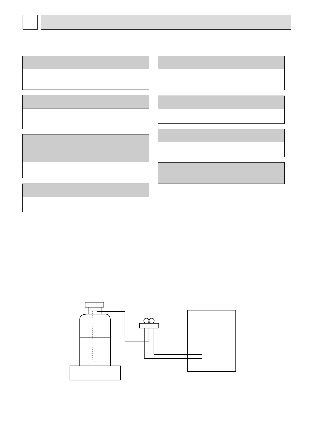
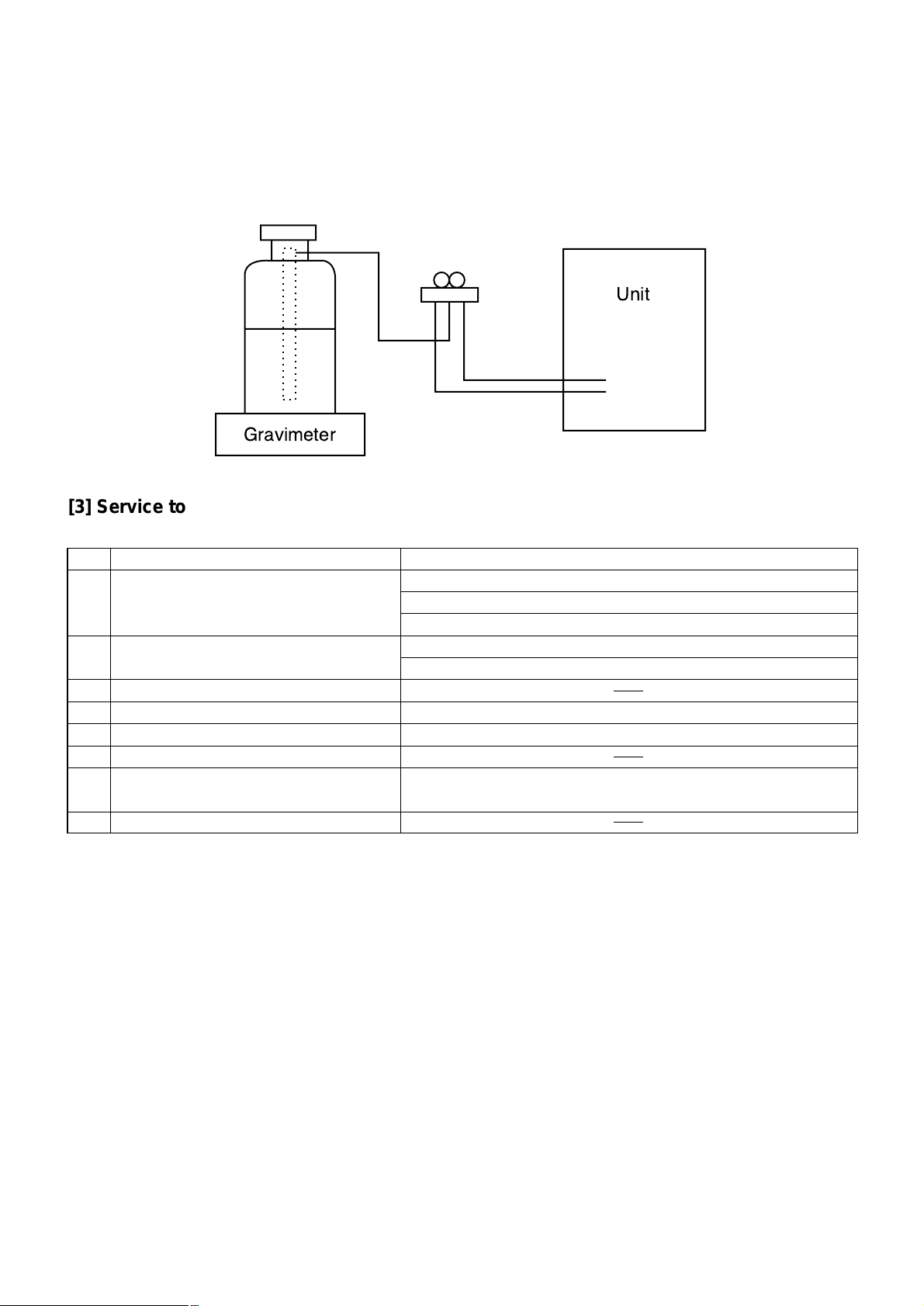
[2] Refrigerant recharging
(1) Refrigerant recharging process
1Direct charging from the cylinder.
·R407C cylinder are available on the market has a syphon pipe.
·Leave the syphon pipe cylinder standing and recharge it.
(By liquid refrigerant)
(2) Recharge in refrigerant leakage case
·After recovering the all refrigerant in the unit, proceed to working.
·Do not release the refrigerant in the air.
·After completing the repair service, recharge the cycle with the specified amount of
liquid refrigerant.
[1] Cautions for service
·After recovering the all refrigerant in the unit, proceed to working.
·Do not release refrigerant in the air.
·After completing the repair service, recharge the cycle with the specified amount of
liquid refrigerant.
Cautions for units utilising refrigerant R407C
CAUTIONS RELATED TO NEW REFRIGERANT
Do not use the existing refrigerant piping.
The old refrigerant and lubricant in the existing piping
contains a large amount of chlorine which may cause the
lubricant deterioration of the new unit.
Use “low residual oil piping”
If there is a large amount of residual oil (hydraulic oil, etc.)
inside the piping and joints, deterioration of the lubricant
will result.
Use ESTER , ETHER or HAB as the lubricant to
coat flares and flange connection parts.
If large amount of mineral oil enter, that can cause
deterioration of refrigerant oil etc.
Use liquid refrigerant to charge the system.
If gas refrigerant is used to seal the system, the composition
of the refrigerant in the cylinder will change and performance
may drop.
Do not use a refrigerant other than R407C.
If another refrigerant (R22, etc.) is used, the chlorine in the
refrigerant may cause the lubricant deterioration.
Use a vacuum pump with a reverse flow check valve.
The vacuum pump oil may flow back into the refrigerant
cycle and cause the lubricant deterioration.
Store the piping to be used during installation
indoors with keep both ends sealed until just
before brazing.
(Store elbows and other joints in a plastic bag.)
If dust, dirt, or water enters the refrigerant cycle,
deterioration of the oil and compressor trouble may result.
Ventilate the room if refrigerant leaks during
operation. If refrigerant comes into contact with
a flame, poisonous gases will be released.
Gravimeter
Unit
SAFETY PRECAUTION
2
Page 4

4
[3] Service tools
Use the below service tools as exclusive tools for R407C refrigerant.
No. Tool name Specifications
1 Gauge manifold ·Only for R407C.
·Use the existing fitting SPECIFICATIONS. (UNF7/16)
·Use high-tension side pressure of 3.43MPa·G or over.
2 Charge hose ·Only for R407C.
·Use pressure performance of 5.10MPa·G or over.
3 Electronic scale
4 Gas leak detector ·Use the detector for R134a or R407C.
5 Adapter for reverse flow check. ·Attach on vacuum pump.
6 Refrigerant charge base.
7 Refrigerant cylinder. ·For R407C ·Top of cylinder (Brown)
·Cylinder with syphon
8 Refrigerant recovery equipment.
Page 5
5
<Cautions for units utilizing refrigerant R410A>
CAUTIONS RELATED TO NEW REFRIGERANT
Use new refrigerant pipes.
In case of using the existing pipes for R22, be careful with
the following.
· For RP100,125 and 140 be sure to perform pipe
replacement operation before test run.
· Use flare nut as provided with this product.
Use a newly flared pipe.
· Avoid using thin pipes. For the detail, please refer to the
outdoor unit service manual.
Do not use refrigerant other than R410A.
If other refrigerant (R22 etc.) is used, chlorine in refrigerant can cause deterioration of refrigerant oil etc.
Use a vacuum pump with a reverse flow check
valve.
If no reverse flow check valve is used, vacuum pump oil
may flow back into refrigerant cycle and that can cause
deterioration of refrigerant oil etc.
Use the following tools specifically designed for
use with R410A refrigerant.
The following tools are necessary to use R410A refrigerant.
Keep the tools with care.
If dirt, dust or moisture enter into refrigerant cycle, that can
cause deterioration of refrigerant oil or malfunction of compressor.
Do not use a charging cylinder without syphone
tube.
If a charging cylinder is used without syphone tube, the
composition of refrigerant will change and the efficiency
will be lowered.
Flare tool
Electronic refrigerant
charging scale
Vacuum pump adaptor
Size adjustment gauge
Gauge manifold
Torque wrench
Gas leak detector
Charge hose
Tools (for R410A)
Make sure that the inside and outside of refrigerant piping is clean and it has no contamination
such as sulfur which is hazardous for use,
oxides, dirt, shaving particles, etc.
In addition, use pipes with specified thickness.
Store the piping to be used during installation
indoors and keep both ends of the piping sealed
until just before brazing. (Leave elbow joints, etc.
in their packaging.)
Use ester oil, ether oil or alkylbenzene oil (small
amount) as the refrigerant oil applied to flares
and flange connections.
Charge refrigerant from liquid phase of gas
cylinder.
If the refrigerant is charged from gas phase, composition
change may occur in refrigerant and the efficiency will be
lowered.
Contamination inside refrigerant piping can cause deterioration of refrigerant oil etc.
If dirt, dust or moisture enter into refrigerant cycle, that can
cause deterioration of refrigerant oil or malfunction of compressor.
If large amount of mineral oil enter, that can cause deterioration of refrigerant oil etc.
Ventilate the room if refrigerant leaks during
operation. If refrigerant comes into contact with
a flame, poisonous gases will be released.
[1] Cautions for installing or relocation of unit
(1) Perform service after collecting the refrigerant left in unit completely.
(2) Do not release refrigerant in the air.
(3) After completing service, charge the system with the specified amount of refrigerant.
(4) When performing service, install a filter drier simultaneously.
Be sure to use a filter drier for new refrigerant.
Page 6
6
Gravimeter
Unit
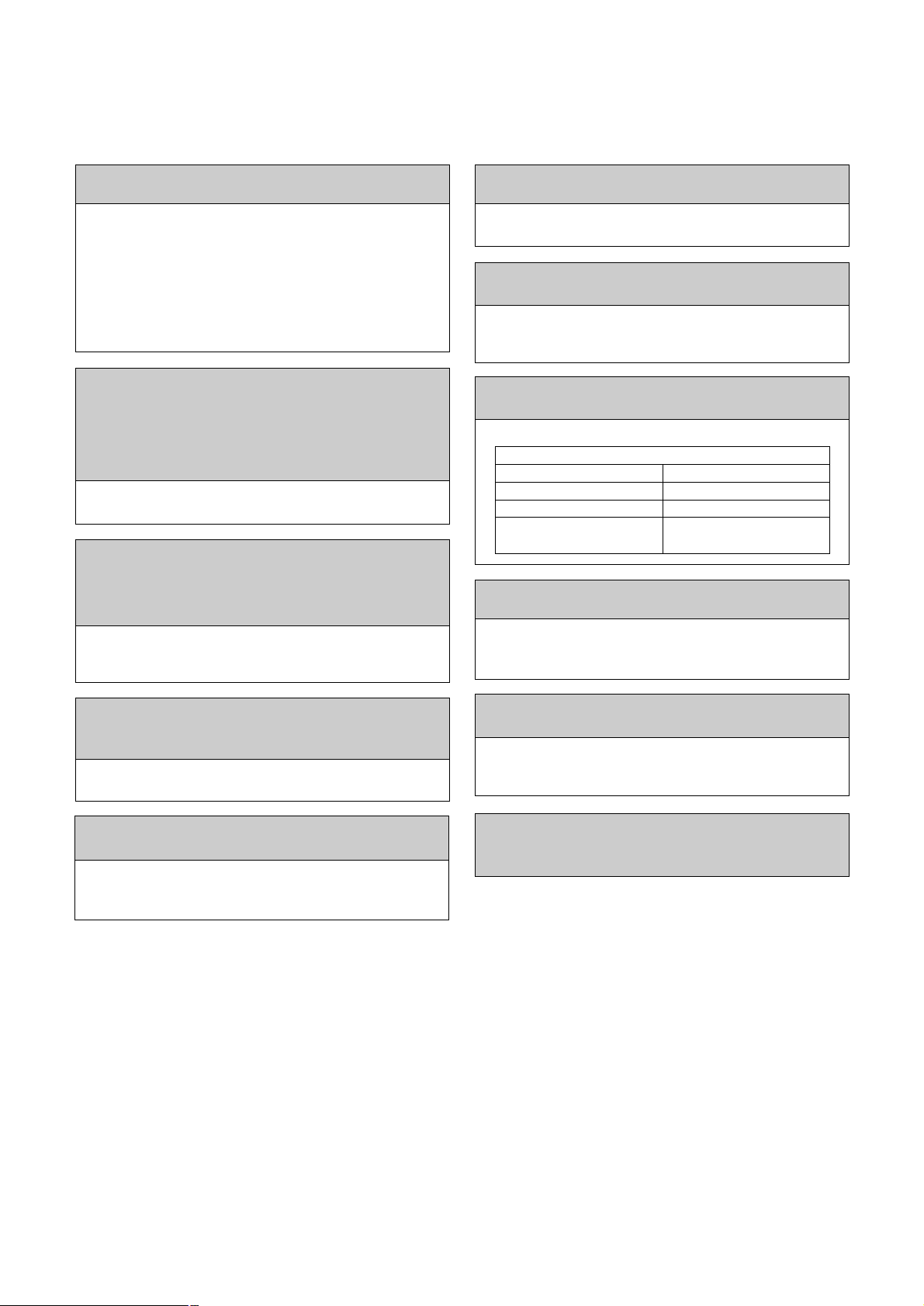
[3] Service tools
Use the below service tools as exclusive tools for R410A refrigerant.
No. Specifications
1
Gauge manifold • Only for R410A
• Use the existing fitting
specifications
. (UNF1/2)
• Use high-tension side pressure of 5.3MPa·G or over.
2
Charge hose • Only for R410A
• Use pressure performance of 5.09MPa·G or over.
3
Electronic scale
4
Gas leak detector • Use the detector for R134a, R407C or R410A.
5
Adaptor for reverse flow check • Attach on vacuum pump.
6
Refrigerant charge base
7
Refrigerant cylinder • Only for R410A Top of cylinder (Pink)
Cylinder with syphon
8
Refrigerant recovery equipment
[2] Additional refrigerant charge
When charging directly from cylinder
Ensure that the cylinder for R410A is syphon type.
Charging should be performed with the syphon cylinder type stood vertically.
(Refrigerant must be charged from liquid phase.)
Page 7
7
PART NAMES AND FUNCTIONS
3
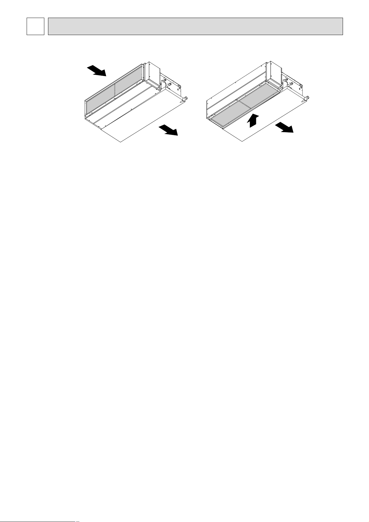
•
Indoor Unit
Air intake (sucks the
air inside the room
into the unit)
In case of rear inlet
Air outlet
In case of bottom inlet
(
Only RP35~60EA
)
RP35EA2
Page 8
8
For purposes of this explanation,
all parts of the display are shown
as lit. During actual operation, only
the relevant items will be lit.
˚F˚C
˚F˚C
ERROR CODE
AFTER
TIMER
TIME SUN MON TUE WED THU FRI SAT
ON
OFF
Hr
AFTER
FILTER
FUNCTION
ONLY1Hr.
WEEKLY
SIMPLE
AUTO OFF
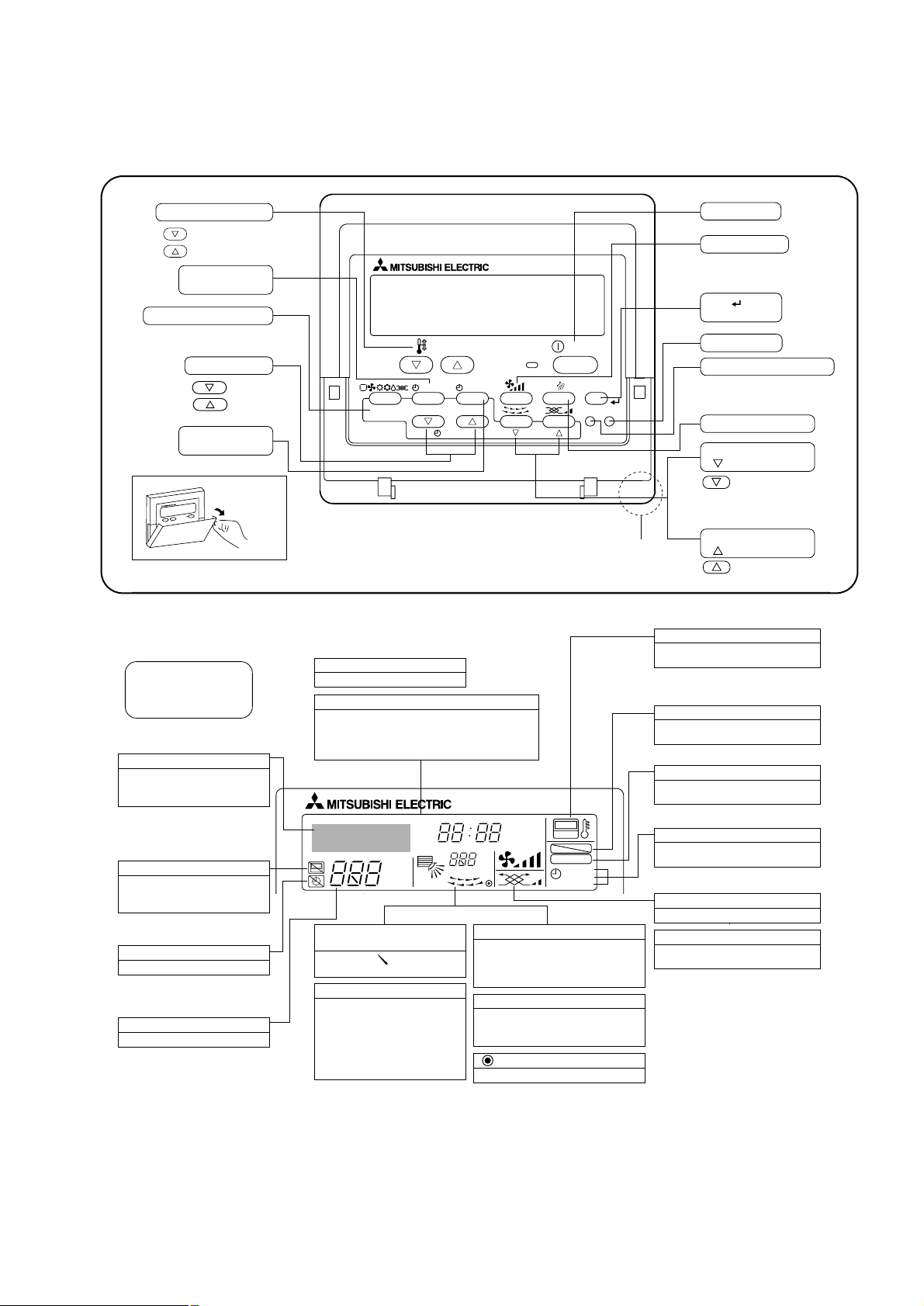
Identifies the current operation
Shows the operating mode, etc.
* Multilanguage display is sup-
ported.
“Centrally Controlled” indicator
Indicates that operation of the remote controller has been prohibited by a master controller.
“Timer is Off” indicator
Indicates that the timer is off.
Temperature Setting
Shows the target temperature.
Day-of-Week
Shows the current day of the week.
Time/Timer Display
Shows the current time, unless the simple or Auto Off
timer is set.
If the simple or Auto Off timer is set, shows the time
remaining.
“Sensor” indication
Displayed when the remote controller
sensor is used.
“Locked” indicator
Indicates that remote controller buttons have been locked.
“Clean The Filter” indicator
Comes on when it is time to clean the
filter.
Timer indicators
The indicator comes on if the corresponding timer is set.
Up/Down Air Direction indicator
The indicator shows the direction of the outcoming airflow.
“One Hour Only” indicator
Displayed if the airflow is set to
weak and downward during COOL
or DRY mode. (Operation varies
according to model.)
The indicator goes off after one
hour, at which time the airflow direction also changes.
Room Temperature display
Shows the room temperature. The room
temperature display range is 8–39°C.
The display flashes if the temperature
is less than 8 °C or 39 °C or more.
Louver display
Indicates the action of the swing louver.
Does not appear if the louver is stationary.
(Power On indicator)
Indicates that the power is on.
Fan Speed indicator
Shows the selected fan speed.
Ventilation indicator
Appears when the unit is running in
Ventilation mode.
• Remote controller
• Display
Once the controls are set, the same operation mode can be repeated by simply pressing the ON/OFF button.
• Operation buttons
PAR-21MAA
ON/OFF
FILTER
CHECK
OPERATION
CLEAR
TEST
TEMP.
MENU
BACK DAY
MONITOR/SET
CLOCK
ON/OFF
Set Temperature buttons
Down
Up
Timer Menu button
(Monitor/Set button)
Mode button (Return button)
Set Time buttons
Back
Ahead
Timer On/Off button
(Set Day button)
Opening the
door.
ON/OFF button
Fan Speed button
Filter button
(<Enter> button)
Test Run button
Check button (Clear button)
Airflow Up/Down button
Louver button
(
Operation button)
To preceding operation
number.
Ventilation button
(
Operation button)
To next operation
number.
Built-in temperature sensor
Caution
● Only the Power on indicator lights when the unit is stopped and power supplied to the unit.
● If you press a button for a feature that is not installed at the indoor unit, the remote controller will display the “Not Available”
message.
If you are using the remote controller to drive multiple indoor units, this message will appear only if the feature is not
present at the parent unit.
● When power is turned ON for the first time, it is normal that “PLEASE WAIT” is displayed on the room temperature indication
(For max. 2minutes). Please wait until this “PLEASE WAIT” indication disappear then start the operation.
Page 9
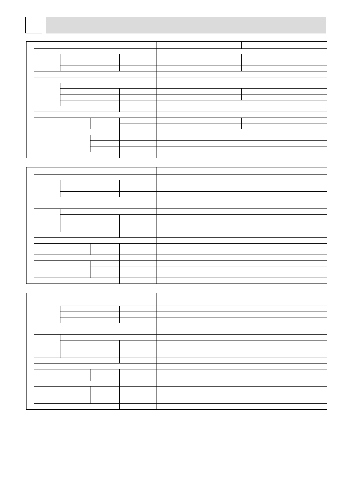
9
Service Ref.
Power supply
Input kW
Running current
❇
1
❇
1
❇
1
❇
1
A
Starting current A
External finish
Heat exchanger
Fan
Fan (drive) × No.
Fan motor output kW
Airflow (Lo-Hi)
m
3
/min <CFM>
External static pressure Pa
Booster heater kW
Operation control & Thermostat
Noise level (Lo-Hi)
dB (A)
Unit drain pipe O.D mm (in.)
Dimensions W mm (in.)
D mm (in.)
H mm (in.)
kg (lbs)
Notes 1. Above data based on indicated voltage
Indoor Unit: Single phase 230V 50Hz
Outdoor Unit: Single phase 230V 50Hz/3 phase 400V 50Hz
INDOOR UNIT
Weight
30Pa
70Pa
Service Ref.
Power supply
Input kW
Running current
❇
1
❇
1
❇
1
❇
1
A
Starting current A
External finish
Heat exchanger
Fan
Fan (drive) × No.
Fan motor output kW
Airflow (Lo-Hi)
m
3
/min <CFM>
External static pressure Pa
Booster heater kW
Operation control & Thermostat
Noise level (Lo-Hi)
dB (A)
Unit drain pipe O.D mm (in.)
Dimensions W mm (in.)
D mm (in.)
H mm (in.)
kg (lbs)
INDOOR UNIT
Weight
30Pa
70Pa
Single phase, 50Hz, 220-240V
Galvanized sheets
Plate fin coil
Centrifugal (direct) × 2
30/70
–
Built in remote controller
R1 (External thread)
935 (36-13/16)
700 (27-5/8)
295 (11-5/8)
33 (73)
0.13
0.55
0.8
0.043
11-14<388-494>
34-38
36-43
0.14
0.61
0.9
0.076
13.5-17<477-600>
36-40
38-44
PEAD-RP35EA PEAD-RP35EA
2
Single phase, 50Hz, 220-240V
0.14
0.61
0.9
Galvanized sheets
Plate fin coil
Centrifugal (direct) × 2
0.076
13.5-17<477-600>
30/70
–
Built in remote controller
36-40
38-44
R1 (External thread)
935 (36-13/16)
700 (27-5/8)
295 (11-5/8)
35 (77)
PEAD-RP50EA
Single phase, 50Hz, 220-240V
0.16
0.70
1.0
Galvanized sheets
Plate fin coil
Centrifugal (direct) × 2
0.116
17-21<600-741>
30/70
–
Built in remote controller
37-41
39-46
R1 (External thread)
1,175 (46-1/8)
700 (27-5/8)
295 (11-5/8)
42 (92)
PEAD-RP60EA
SPECIFICATION
4
Page 10
10
Service Ref.
Power supply
Input kW
Running current
❇
1
❇
1
❇
1
❇
1
A
Starting current A
External finish
Heat exchanger
Fan
Fan (drive) × No.
Fan motor output kW
Airflow (Lo-Hi)
m
3
/min <CFM>
External static pressure Pa
Booster heater kW
Operation control & Thermostat
Noise level (Lo-Hi)
dB (A)
Unit drain pipe O.D mm (in.)
Dimensions W mm (in.)
D mm (in.)
H mm (in.)
kg (lbs)
INDOOR UNIT
Weight
70Pa
(130Pa)
Notes 1. Above data based on indicated voltage
Indoor Unit: Single phase 230V 50Hz
Outdoor Unit: Single phase 230V 50Hz/3 phase 400V 50Hz
Single phase, 50Hz, 220-240V
0.35
1.55
2.0
Galvanized sheets
Plate fin coil
Centrifugal (direct) × 2
0.15
20-25<706-883>
70/(130)
–
Built in remote controller
37-41
40-45
R1 (External thread)
1,175 (46-1/8)
740 (29-1/8)
325 (12-13/16)
44 (97)
PEAD-RP71EA
Single phase, 50Hz, 220-240V
Galvanized sheets
Plate fin coil
Centrifugal (direct) × 2
70/(130)
–
Built in remote controller
R1 (External thread)
1,415 (55-11/16)
740 (29-1/8)
325 (12-13/16)
0.57
2.53
3.2
0.24
27-34<953-1,200>
41-46
42-48
62 (136)
0.59
2.62
3.4
0.27
33.5-42<1,183-1,483>
44-50
46-52
65 (143)
PEAD-RP100EA PEAD-RP100EA
2
Single phase, 50Hz, 220-240V
0.59
2.62
3.4
Galvanized sheets
Plate fin coil
Centrifugal (direct) × 2
0.27
33.5-42<1,183-1,483>
70/(130)
–
Built in remote controller
44-50
46-52
R1 (External thread)
1,415 (55-11/16)
740 (29-1/8)
325 (12-13/16)
65 (143)
PEAD-RP125EA
Page 11
11
Service Ref.
Power supply
Input kW
Running current
❇
1
❇
1
❇
1
❇
1
A
Starting current A
External finish
Heat exchanger
Fan
Fan (drive) × No.
Fan motor output kW
Airflow (Lo-Hi)
m
3
/min <CFM>
External static pressure Pa
Booster heater kW
Operation control & Thermostat
Noise level (Lo-Hi)
dB (A)
Unit drain pipe O.D mm (in.)
Dimensions W mm (in.)
D mm (in.)
H mm (in.)
kg (lbs)
INDOOR UNIT
Weight
70Pa
(130Pa)
Notes 1. Above data based on indicated voltage
Indoor Unit: Single phase 230V 50Hz
Outdoor Unit: Single phase 230V 50Hz/3 phase 400V 50Hz
Single phase, 50Hz, 220-240V
0.61
2.69
3.5
Galvanized sheets
Plate fin coil
Centrifugal (direct) × 2
0.27
36.5-46<1,288-1,624>
70/(130)
–
Built in remote controller
46-51
47-53
R1 (External thread)
1,715 (67-1/2)
740 (29-1/8)
325 (12-13/16)
70 (154)
PEAD-RP140EA
Page 12
12
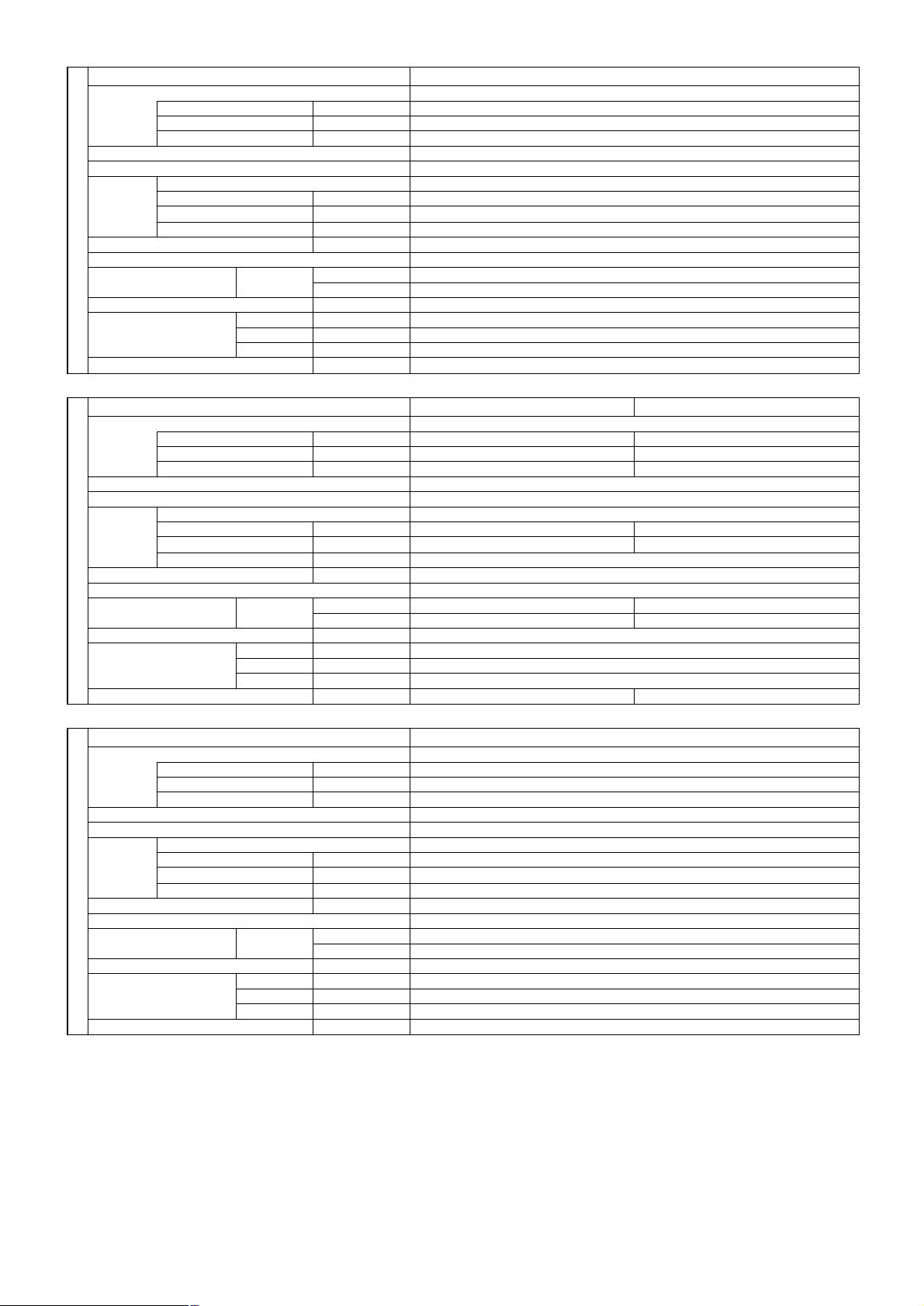
PEAD-RP35EA
PEAD-RP50EA, PEAD-RP35EA2
FAN PERFORMANCE AND CORRECTED AIR FLOW
5
100
80
60
40
(1Pa 0.1mmAq)
20
External static pressure (Pa)
140
120
100
80
60
40
(1Pa 0.1mmAq)
External static pressure (Pa)
20
Fan Performance <30Pa>
Hi
Lo
610121416
8
Air Flow (CMM)
Fan Performance <70Pa>
Hi
Lo
Corrected Air Flow
Cooling
1.1
1.0
0.9
0.8
Correction factor
10 12 14 16 18 20
Air flow (CMM)
Heating
1.3
1.2
1.1
1.0
Correction factor
0.9
0.8
81012141618
Air flow (CMM)
Capacity
input
10 126 8 14 16 18
Air Flow (CMM)
140
120
100
(1Pa 0.1mmAq)
External static pressure (Pa)
160
140
120
100
Fan Performance <30Pa>
80
60
40
20
6 8 10 12 14 16 18 20
Air Flow (CMM)
Fan Performance <70Pa>
80
Hi
Lo
Hi
Corrected Air Flow
Cooling
1.1
1.0
0.9
0.8
Correction factor
810121416182022
Air flow (CMM)
Heating
1.3
1.2
1.1
1.0
Capacity
input
60
(1Pa 0.1mmAq)
40
External static pressure (Pa)
20
8 10121416182022
Lo
Air Flow (CMM)
Correction factor
0.9
0.8
810121416182022
Air flow (CMM)
Page 13
13
140
120
100
200
180
160
80
60
40
20
12 16 20 24 28 32
Air flow
(CMM)
Fan performance <130Pa>
External static pressure (Pa)
(1Pa 0.1mmAq)
140
120
100
180
160
80
60
40
20
12 16 20 24 28 32
Air flow
(CMM)
Fan performance <70Pa>
External static pressure (Pa)
(1Pa 0.1mmAq)
=
Lo
Hi
Corrected Air Flow
Capacity
Input
1.1
1.0
0.9
0.8
12 16 20 24 28 32
Air flow (CMM)
Correction factor
Cooling
=
Hi
Lo
1.1
1.0
1.3
1.2
0.9
0.8
12 16 20 24 28 32
Air flow (CMM)
Correction factor
Heating
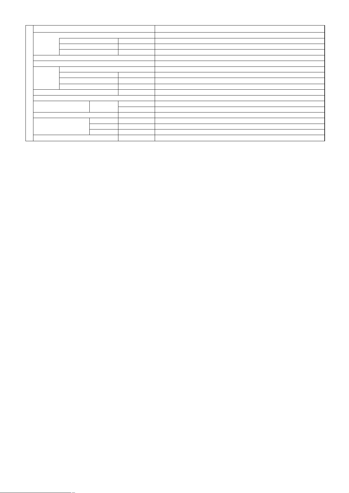
PEAD-RP71EA
PEAD-RP60EA
Fan Performance <30Pa>
120
100
80
60
40
(1Pa 0.1mmAq)
20
External static pressure (Pa)
8 1012141618202224
Fan Performance <70Pa>
140
120
100
80
Lo
Air Flow (CMM)
Corrected Air Flow
Capacity
input
Cooling
1.1
1.0
Hi
0.9
0.8
Correction factor
12 14 16 18 20 22 24 26
Air flow (CMM)
Heating
1.3
1.2
1.1
Hi
1.0
60
40
(1Pa 0.1mmAq)
External static pressure (Pa)
20
10 12 14 16 18 20 22 24 26
Lo
Air Flow (CMM)
Correction factor
0.9
0.8
12 14 16 18 20 22 24 26
Air flow (CMM)
Page 14

14
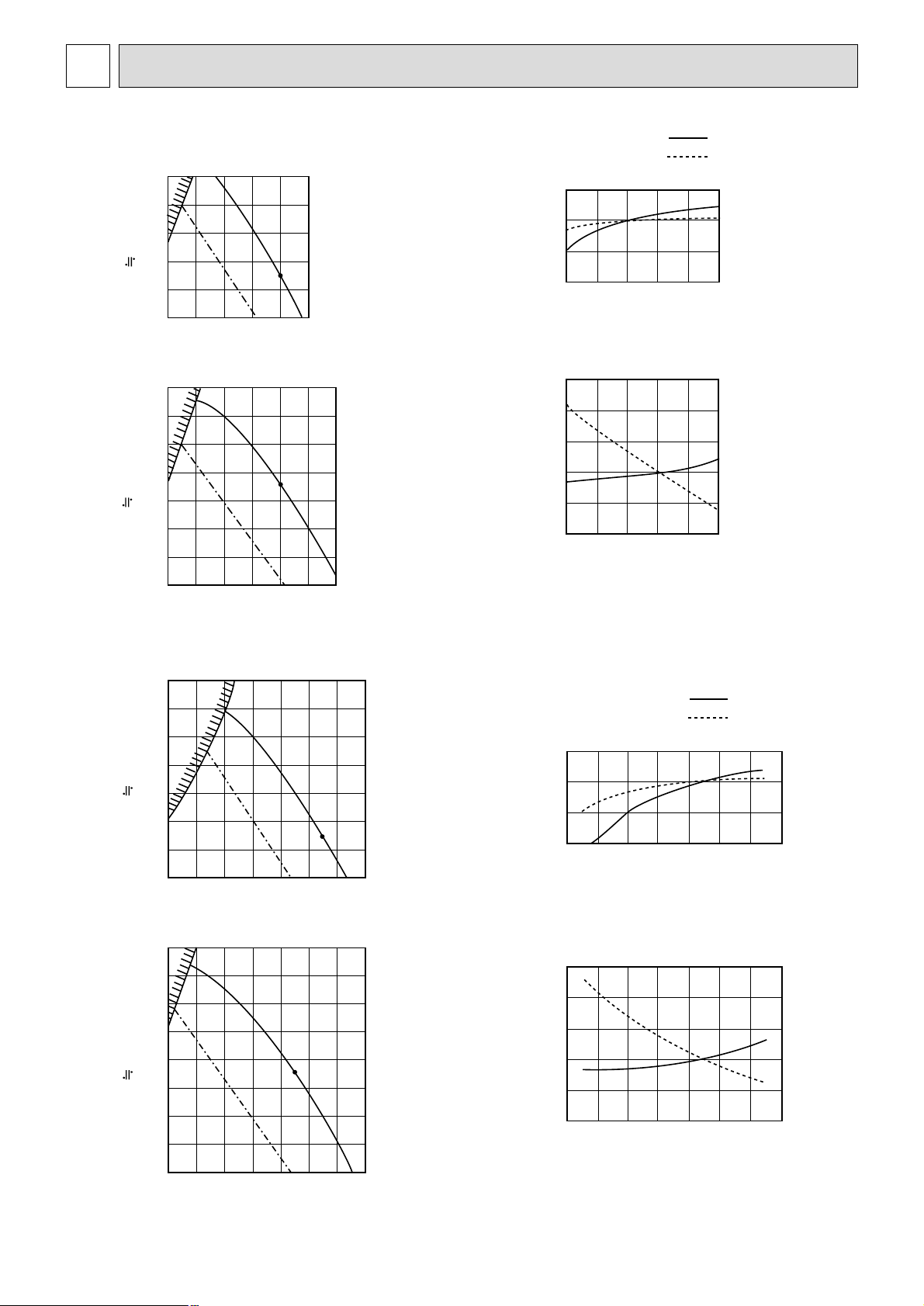
PEAD-RP100EA
PEAD-RP125EA, PEAD-RP100EA2
Fan performance <130Pa>
200
180
160
140
120
100
80
=
60
Lo
40
(1Pa 0.1mmAq)
20
External static pressure (Pa)
26 28 30 32 34 36 38 40
Air flow
Corrected Air Flow
Cooling
1.1
Hi
(CMM)
Capacity
Input
Fan performance <70Pa>
220
200
180
160
140
120
100
80
=
60
40
(1Pa 0.1mmAq)
20
External static pressure (Pa)
24 26 28 30 32 34 36 38
Air flow
Heating
1.2
1.1
Hi
Lo
(CMM)
1.0
0.9
Correction factor
0.8
24 26 28 30 32 34 36 38 40
Air flow (CMM)
Fan performance <130Pa>
220
200
180
160
140
120
100
80
=
60
(1Pa 0.1mmAq)
40
20
External static pressure (Pa)
Lo
32 34 36 38 40 42 44 46 48
Air flow
(CMM)
Hi
1.0
0.9
Correction factor
0.8
24 26 28 30 32 34 36 38 40
Air flow (CMM)
Fan performance <70Pa>
220
200
180
160
140
120
100
80
=
60
(1Pa 0.1mmAq)
40
20
External static pressure (Pa)
32 34 36 38 40 42 44 46
Air flow
Hi
Lo
(CMM)
Corrected Air Flow
Correction factor
Cooling
1.1
1.0
0.9
0.8
32 34 36 38 40 42 44 46 48
Input
Air flow (CMM)
Capacity
Heating
1.2
1.1
1.0
0.9
Correction factor
0.8
32 34 36 38 40 42 44 46 48
Air flow (CMM)
Page 15

15
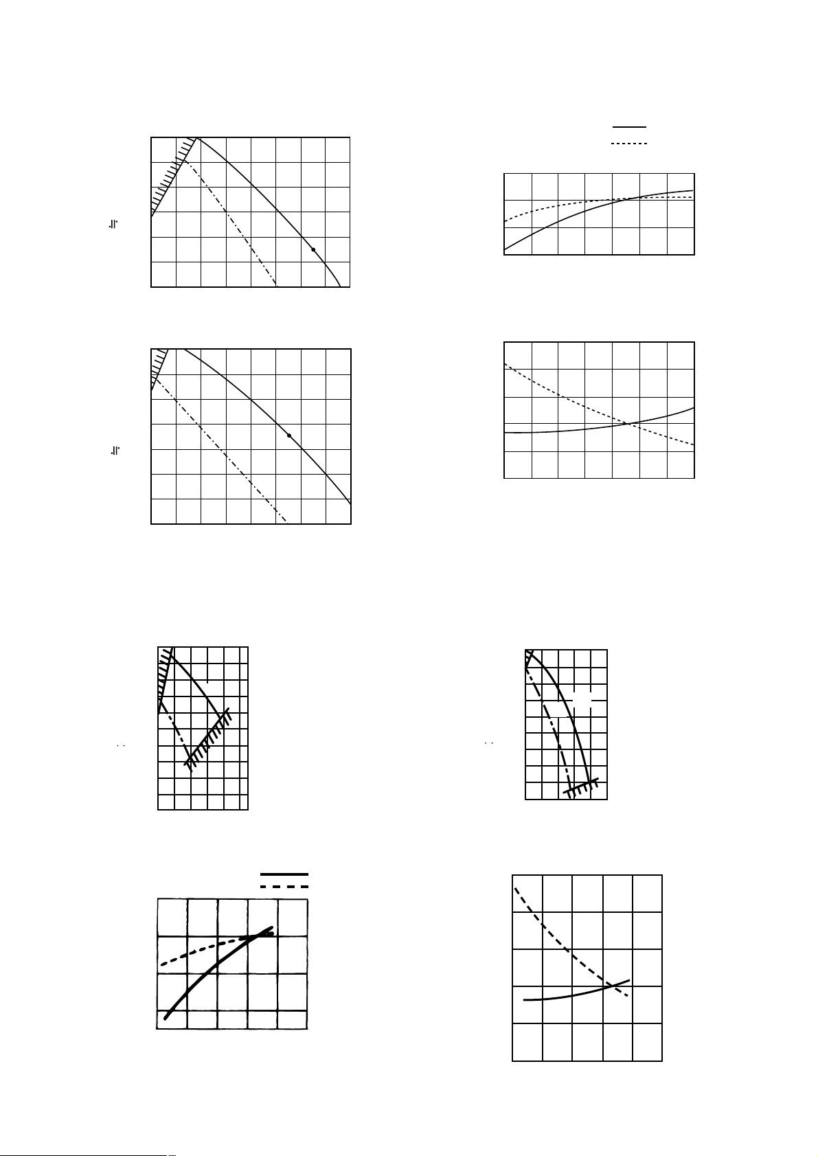
PEAD-RP140EA
220
200
180
160
140
120
100
=
80
60
(1Pa 0.1mmAq)
40
20
External static pressure (Pa)
Lo
38 40 42 44 46 48 50
36
Air flow
Hi
52
(CMM)
Corrected Air Flow
Cooling
1.1
1.0
0.9
Correction factor
0.8
36 38 40 42 44 46
Air flow (CMM)
Capacity
Input
48 50
52
200
180
160
140
120
=
100
80
(1Pa 0.1mmAq)
60
40
External static pressure (Pa)
20
Lo
38 40 42 44 46 48
36
Air flow
Hi
(CMM)
Heating
1.2
1.1
1.0
0.9
Correction factor
0.8
36 38 40 42 44 46
Air flow (CMM)
50
48
50 52
Page 16

16
PEAD-RP35EA
NC60
NC50
NC40
NC30
NC20
70
60
50
40
30
20
63 125 250 500 1000 2000 4000 8000
10
0
OCTAVE BAND PRESSURE LEVEL (dB) 0dB = 20µPa
OCTAVE BAND CENTER FREQUENCIES (Hz)
High
Low
High
Low
Approximate minimum
audible limit on
continuous noise
NC60
NC50
NC40
NC30
NC20
70
60
50
40
30
20
63 125 250 500 1000 2000 4000 8000
10
0
OCTAVE BAND PRESSURE LEVEL (dB) 0dB = 20µPa
OCTAVE BAND CENTER FREQUENCIES (Hz)
High
Low
High
Low
High
Low
High
Low
Approximate minimum
audible limit on
continuous noise
NC60
NC50
NC40
NC30
NC20
70
60
50
40
30
20
63 125 250 500 1000 2000 4000 8000
10
0
OCTAVE BAND PRESSURE LEVEL (dB) 0dB = 20µPa
OCTAVE BAND CENTER FREQUENCIES (Hz)
Approximate minimum
audible limit on
continuous noise
NC60
NC50
NC40
NC30
NC20
70
60
50
40
30
20
63 125 250 500 1000 2000 4000 8000
10
0
OCTAVE BAND PRESSURE LEVEL (dB) 0dB = 20µPa
OCTAVE BAND CENTER FREQUENCIES (Hz)
Approximate minimum
audible limit on
continuous noise
NC60
NC50
NC40
NC30
NC20
70
60
50
40
30
20
63 125 250 500 1000 2000 4000 8000
10
0
OCTAVE BAND PRESSURE LEVEL (dB) 0dB = 20µPa
OCTAVE BAND CENTER FREQUENCIES (Hz)
Approximate minimum
audible limit on
continuous noise
NC60
NC50
NC40
NC30
NC20
70
60
50
40
30
20
63 125 250 500 1000 2000 4000 8000
10
0
OCTAVE BAND PRESSURE LEVEL (dB) 0dB = 20µPa
OCTAVE BAND CENTER FREQUENCIES (Hz)
Approximate minimum
audible limit on
continuous noise
(External static
pressure 30Pa)
PEAD-RP35EA
(External static
pressure 70Pa)
PEAD-RP50EA
PEAD-RP35EA
2
(External static
pressure 30Pa)
PEAD-RP50EA
PEAD-RP35EA
2
(External static
pressure 70Pa)
PEAD-RP60EA
(External static
pressure 30Pa)
PEAD-RP60EA
(External static
pressure 70Pa)
2)NC curves
Ceiling concealed
Noise level at anechoic room (Low-High) Unit : dB(A)
❇ Optional motor
Model
30Pa
34-38 36-43 -
36-40 38-44 37-41 39-46 -
- 37-41 40-45
- 41-46 42-48
-
44-50 46-52
-
46-51 47-53
70Pa 130Pa
External static pressure
❈
❈
❈
❈
PEAD-RP35EA
PEAD-RP50EA
PEAD-RP35EA
2
PEAD-RP60EA
PEAD-RP71EA
PEAD-RP100EA
PEAD-RP125EA
PEAD-RP100EA
2
PEAD-RP140EA
2m
Aux.duct
1m
1.5m
Measured point
1)Noise level
SOUND LEVELS
6
Page 17

17
PEAD-RP100EA
NC60
NC50
NC40
NC30
NC20
70
60
50
40
30
20
63 125 250 500 1000 2000 4000 8000
10
0
OCTAVE BAND PRESSURE LEVEL (dB) 0dB = 20µPa
OCTAVE BAND CENTER FREQUENCIES (Hz)
High
Low
High
Low
Approximate minimum
audible limit on
continuous noise
NC60
NC50
NC40
NC30
NC20
70
60
50
40
30
20
63 125 250 500 1000 2000 4000 8000
10
0
OCTAVE BAND PRESSURE LEVEL (dB) 0dB = 20µPa
OCTAVE BAND CENTER FREQUENCIES (Hz)
High
Low
High
Low
High
Low
High
Low
Approximate minimum
audible limit on
continuous noise
NC60
NC50
NC40
NC30
NC20
70
60
50
40
30
20
63 125 250 500 1000 2000 4000 8000
10
0
OCTAVE BAND PRESSURE LEVEL (dB) 0dB = 20µPa
OCTAVE BAND CENTER FREQUENCIES (Hz)
Approximate minimum
audible limit on
continuous noise
NC60
NC50
NC40
NC30
NC20
70
60
50
40
30
20
63 125 250 500 1000 2000 4000 8000
10
0
OCTAVE BAND PRESSURE LEVEL (dB) 0dB = 20µPa
OCTAVE BAND CENTER FREQUENCIES (Hz)
Approximate minimum
audible limit on
continuous noise
NC60
NC50
NC40
NC30
NC20
70
60
50
40
30
20
63 125 250 500 1000 2000 4000 8000
10
0
OCTAVE BAND PRESSURE LEVEL (dB) 0dB = 20µPa
OCTAVE BAND CENTER FREQUENCIES (Hz)
Approximate minimum
audible limit on
continuous noise
NC60
NC50
NC40
NC30
NC20
70
60
50
40
30
20
63 125 250 500 1000 2000 4000 8000
10
0
OCTAVE BAND PRESSURE LEVEL (dB) 0dB = 20µPa
OCTAVE BAND CENTER FREQUENCIES (Hz)
Approximate minimum
audible limit on
continuous noise
(External static
pressure 70Pa)
PEAD-RP100EA
(External static
pressure 130Pa)
PEAD-RP125EA
PEAD-RP100EA
2
(External static
pressure 70Pa)
PEAD-RP125EA
PEAD-RP100EA
2
(External static
pressure 130Pa)
PEAD-RP140EA
(External static
pressure 70Pa)
PEAD-RP140EA
(External static
pressure 130Pa)
High
Low
High
Low
NC60
NC50
NC40
NC30
NC20
70
60
50
40
30
20
63 125 250 500 1000 2000 4000 8000
10
0
OCTAVE BAND PRESSURE LEVEL (dB) 0dB = 20µPa
OCTAVE BAND CENTER FREQUENCIES (Hz)
Approximate minimum
audible limit on
continuous noise
NC60
NC50
NC40
NC30
NC20
70
60
50
40
30
20
63 125 250 500 1000 2000 4000 8000
10
0
OCTAVE BAND PRESSURE LEVEL (dB) 0dB = 20µPa
OCTAVE BAND CENTER FREQUENCIES (Hz)
Approximate minimum
audible limit on
continuous noise
PEAD-RP71EA
(External static
pressure 70Pa)
PEAD-RP71EA
(External static
pressure 130Pa)
Page 18

18
7
OUTLINES & DIMENSIONS
1. INDOOR UNIT
PEAD-RP35, 50, 60EA, RP35EA
2
R407C Outdoor unit;9.52
F
R410A Outdoor unit;6.35 ❊
EDCBA
804830
-
305772
Model
RP60
R407C Outdoor unit;15.88
G
R410A Outdoor unit;12.7 ❊
Other outdoor unit;9.52 ❊
Outdoor unit(MUZ,SUZ);6.35
15.88104410702902801012
RP35,50
❊ Setting at shipment
Service space:640 or more
Keep duct-work length 850mm or more.
Be sure to change the position of air filter to the position where it can be serviced.
355
B
56
10
18
818155
197
159
243
50~150
365~465
2
1
3
4
Air inlet
Air outlet
Service space:500 or more
Refrigerant piping flare connection (liquid ø F copper tube):HP
Refrigerant piping flare connection (gas ø G copper tube):LP
Drain R1(External thread)
Electrical parts box
Drain Pump (Option)
Drain Pipe (Option)···Flexible joint VP-25(I.D.ø32)
Air Filter
1
2
3
4
5
6
7
5
6
75
44
7
Air outlet
Air inlet
7
(All around)
(All around)
(All around)
Lifting bolt hole
(14X22)
10-ø3(RP35,50)
12-ø3(RP60)
In case of rear inlet
In case of bottom inlet
10-ø3(RP35,50)
12-ø3(RP60)
3.5 288 3.5
21
3.5
13
13
C
BC
C B
109
176
176
E
10
10
80
61
29 A
81
A
40
30
10
256
227
640
24
35
30
10
179
10
15
40
256
81
A
81
85
282
450
450
D 30
10-ø3(RP35,50)
12-ø3(RP60)
Set
277
45
Access door
Service space:680 or more
Keep duct-work length 850mm or more.
Be sure to change the position of
air filter to the position where it can
be serviced.
3.5
319
30
3.5
29
13
7544
81
323
81
55
197
243
308
50~150
365~465
2
1
3
4
Air inlet
Air outlet
Service space:500 or more
5
6
7
(All around)
(All around)
122
45
307
113
Lifting bolt hole
(14X22)
12-ø3
D
E 13
375
BC
BC
140
181
10
10
80
68030
40
16953
30
A
81
81
A
261
20
35
210
30
10
282
450
450
12-ø3
❊ Setting at shipment
R407C Outdoor unit;19.05
158416104704601552RP140
15.8810441070290
F
R410A Outdoor unit;15.88 ❊
EDCBA
12841310370360
2801012
1252
Model
RP100,125
RP71
Refrigerant piping flare connection (liquid ø9.52 copper tube):HP
Refrigerant piping flare connection (gas ø F copper tube):LP
Drain R1 (External thread)
Electrical parts box
Drain Pump (Option)
Drain Pipe (Option)···Flexible joint VP25(I.D.ø32)
Air Filter
7
6
5
4
3
2
1
Set
Access door
PEAD-RP71, 100, 125, 140EA, RP100EA2
Page 19

19
2. REMOTE CONTROLLER
(Front view) (Side view) (Rear view)
120
130
19
83.5
46
Page 20

20
8
WIRING DIAGRAM
TO OUTDOOR UNIT
TO MA-REMOTE
CONTROLLER
DC8.7-13V
I.B.
X6
X4
X5
X1
ZNR
FUSE
P.B.
<❊A>
N
L
S1
S2
12
21
12
S3
TO CND
TO OUTDOOR
UNIT
TO CN3C
CN31
1
3
DS
INSIDE SECTION OF CONTROL BOX
(OPTIONAL PARTS)
DRAIN PUMP
B
L
U
B
L
U
B
L
U
B
L
U
TB5
(RED)
643521
C
MF
X6X5X4
X1
(RED)
CNDK
(BLU)
CNP
(WHT)
FAN
1
Y
L
W
O
R
N
(ORN)
31
CND
2
1
(RED)
LED1
LED2
LED3
CN2L
OFF
ON
SWE
SW2
SW1
ON
OFF
12345
ON
OFF
12345
ON
OFF
12345
ON
OFF
12345
ON
OFF
12345
ON
OFF
12345
ON
OFF
12345
54321
OFF
ON
50EA
60EA
71EA
35EA(2)
100EA(2)
125EA
140EA
Capacity cord
switch
Model selection
switch
SW2
SW1
MODELS
(RED)
(WHT)
P
N
K
P
N
K
B
L
K
B
L
K
W
H
T
B
L
K
B
L
K
W
H
T
W
H
T
W
H
T
1
2
31
CN2S
CNSK
(WHT)
(RED)
YLW
ORN
BRN
B
R
N
O
R
N
(BLU)
WHT
BLK
CN2D
(WHT)
(BLU)
(RED)
(WHT)
(BLK)
(WHT)
(WHT)
(WHT)
(YLW)
(WHT)
(WHT)
❊A
DP
643521
2
1
TB4
S3
S1
S2
2
1331
643521
MF
C
12
CN24
321
12
3
1
2
121
2
TH5TH2TH1
1
2
CN3C
31
1375
CN22
CN20 CN21 CN29
CN31
CN90
CN41
CN51
CN32
2
1
123456789 432154321
POWER SUPPLY
~(1PHASE)
230V 50Hz
(IN CASE OF CONNECT
THE REPLACEMENT WIRING)
<PEAD-RP71·100·125·140EA,100EA2>
External static
pressure 130Pa
<PEAD-RP71·100·125·140EA,100EA
2
>
External static pressure 70Pa
<PEAD-RP35·50·60EA,35EA
2
>
External static
pressure 70Pa
Optional parts
Optional parts
<PEAD-RP35·50·60EA,35EA2>
External static
pressure 30Pa
RELAY(DRAIN PUMP)
X1
CONNECTOR(WIRELESS) DP
DS
TRANSMISSION(INDOOR.OUTDOOR)
LED3
SWITCH(MODEL SELECTION)
SW1
POWER SUPPLY(REMOTE CONTROLLER)
LED2
LED1
POWER SUPPLY(I.B.)
CN90
CN51
CONNECTOR(CENTRALLY CONTROL)
CN24 CONNECTOR(HEATER)
VARISTOR
FUSE(T6.3AL250V)
ZNR
FUSE
INDOOR POWER BOARD
P.B.
COND./EVA. TEMP. THERMISTOR
(0
°C/15KΩ,25°C/5.4KΩ DETECT)
PIPE TEMP. THERMISTOR/LIQUID
(0
°C/15KΩ,25°C/5.4KΩ DETECT)
INTAKE AIR TEMP. THERMISTOR
(0
°C/15KΩ,25°C/5.4KΩ DETECT)
TERMINAL BLOCK(REMOTE CONTROLLER)
FAN MOTOR
CAPACITOR(FAN MOTOR)
DRAIN SENSOR
DRAIN PUMP
TH5
TH2
TH1
TB5
(INDOOR/OUTDOOR CONNECTING LINE)
TERMINAL BLOCKTB4
MF
C
NAMENAME
SYMBOLSYMBOL
NAME
RELAY(FAN MOTOR)
RELAY(FAN MOTOR)
SWITCH(CAPACITY CORD)
CONNECTOR(HA TERMINAL-A)
CONNECTOR(REMOTE SWITCH)
INDOOR CONTROLLER BOARD
RELAY(FAN MOTOR)
SWITCH(EMERGENCY OPERATION)
CONNECTOR(LOSSNAY)
X6
X5
X4
SWE
SW2
CN41
CN32
CN2L
I.B.
SYMBOL
NOTE 1.SINCE THE OUTDOOR SIDE ELECTRIC WIRING MAY CHANGE BE SURE
TO CHECK THE OUTDOOR UNIT ELECTRIC WIRING FOR SERVICING.
2.INDOOR AND OUTDOOR CONNECTING WIRES ARE MADE WITH POLARITIES,
MAKE WIRING MATCHING TERMINAL NUMBERS(S1,S2,S3).
3.SYMBOLS USED IN WIRING DIAGRAM ABOVE ARE,
:CONNECTOR, :TERMINAL.
4.THE WIRING BETWEEN MA-REMOTE CONTROLLER AND TB5 IS INCLUDED
IN THE PACKAGE.
PEAD-RP35, 50, 60, 71, 100, 125, 140EA
PEAD-RP35, 100EA
2
Page 21

21
9
REFRIGERANT SYSTEM DIAGRAM
PEAD-RP35, 50, 60, 71, 100, 125, 140EA
PEAD-RP35, 100EA
2
Indoor unit
Indoor
heat
exchanger
Thermistor TH5
(Cond./Eva.
temperature)
Strainer
Refrigerant flow in cooling
Refrigerant flow in heating
Refrigerant GAS pipe connection
Thermistor TH1
(Room temperature)
Thermistor TH2
Pipe temperature
(Liquid)
Distributor
with strainer
Refrigerant LIQUID pipe connection
Page 22

22
10
TROUBLESHOOTING
<Error code display by self-diagnosis and actions to be taken for service (summary)>
Present and past error codes are logged and displayed on the wired remote controller or controller board of outdoor unit.
Actions to be taken for service and the inferior phenomenon reoccurrence at field are summarized in the table below. Check
the contents below before investigating details.
10-1.TROUBLESHOOTING
Unit conditions at service
Error code
Actions to be taken for service (summary)
The inferior phenomenon is
reoccurring.
Displayed
Not displayed
Judge what is wrong and take a corrective action
according to “SELF-DIAGNOSIS ACTION TABLE” (10-2).
Identify the cause of the inferior phenomenon and take
a corrective action according to “TROUBLESHOOTING
BY INFERIOR PHENOMENA ” (10-3).
The inferior phenomenon is
not reoccurring.
Logged
Not logged
1Consider the temporary defects such as the work of
protection devices in the refrigerant circuit including
compressor, poor connection of wiring, noise and etc.
Re-check the symptom, and check the installation
environment, refrigerant amount, weather when the
inferior phenomenon occurred, and wiring related.
2Reset error code logs and restart the unit after finishing
service.
3There is no abnormality in electrical components,
controller boards, and remote controller.
1Recheck the abnormal symptom.
2Identify the cause of the inferior phenomenon and take
a corrective action according to “TROUBLESHOOTING
BY INFERIOR PHENOMENA ” (10-3).
3Continue to operate unit for the time being if the cause
is not ascertained.
4There is no abnormality in electrical components,
controller boards, remote controller etc.
Page 23

23
10-2. SELF-DIAGNOSIS ACTION TABLE
Note: Refer to the manual of outdoor unit for the details of display
such as F, U, and other E.
Error Code
Meaning of error code and detection method
Cause
Countermeasure
P1
Abnormality of room temperature
thermistor (TH1)
1 The unit is in three-minute resume
prevention mode if short/open of
thermistor is detected. Abnor mal if the
unit does not reset normally after three
minutes. (The unit returns to normal
operation, if it has normally reset.)
2 Constantly detected during cooling,
drying, and heating operation.
Short: 90
: or more
Open: -40
: or less
1 Defective thermistor
characteristics.
2 Contact failure of connector
(CN20) on the indoor controller
board. (Inser t failure)
3 Breaking of wire or contact
failure of thermistor wiring.
4 Defective indoor controller
board.
1–3 Check resistance value of thermistor.
0
: ······15.0k"
10: ····9.6k"
20: ····6.3k"
30: ····4.3k"
40: ····3.0k"
If you put force on (draw or bend) the lead wire
with measuring resistance value of thermistor
breaking of wire or contact failure can be
detected.
2 Check contact failure of connector (CN20) on
the indoor controller board. Refer to 10-6.
Turn the power on again and check restart
after inserting connector again.
4 Check room temperature display on remote
controller.
Replace indoor controller board if there is
abnormal difference with actual room
temperature.
Turn the power off, and on again to operate
after check.
P2
Abnormality of pipe temperature
thermistor/Liquid (TH2)
1 The unit is in three-minute resume
prevention mode if short/open of
thermistor is detected. Abnor mal if the
unit does not reset normally after three
minutes. (The unit returns to normal
operation, if it has normally reset.)
2 Constantly detected during cooling,
drying, and heating (except defrosting)
operation.
Short: 90
: or more
Open: -40
: or less
1 Defective thermistor
characteristics.
2 Contact failure of connector
(CN21) on the indoor controller
board. (Inser t failure)
3 Breaking of wire or contact
failure of thermistor wiring.
4 Defective refrigerant circuit is
causing thermistor temperature
of 90
: or more or -40: or
less.
5 Defective indoor controller board.
1–3 Check resistance value of thermistor.
For characteristics, refer to (P1) above.
2 Check contact failure of connector (CN21) on
the indoor controller board. Refer to 10-6.
Turn the power on and check restart after
inserting connector again.
4 Check pipe <liquid> temperature with remote
controller in test run mode. If pipe <liquid>
temperature is exclusively low (in cooling
mode) or high (in heating mode), refrigerant
circuit may have defective.
5 Check pipe <liquid> temperature with remote
controller in test run mode. If there is exclusive
difference with actual pipe <liquid> temperature,
replace indoor controller board.
Turn the power off, and on again to operate
after check.
P4
Abnormality of drain sensor (DS)
1 Suspensive abnormality, if short/open of
thermistor is detected for 30 seconds
continuously.
Turn off compressor and indoor fan.
2 Shor t/open is detected for 30 seconds
continuously during suspensive
abnormality.
(The unit returns to normal operation,
if it has normally reset.)
3 Detect the following condition.
• During cooling and drying operation.
• In case that pipe <liquid> temperature
- room temperature <-10deg
(Except defrosting)
• When pipe <liquid> temperature or
room temperature is short/open
temperature.
• During drain pomp operation.
1 Defective thermistor
characteristics
2 Contact failure of connector
(CN31) on the indoor controller
board. (Inser t failure).
3 Breaking of wire or contact
failure of drain sensor wiring.
4 Defective indoor controller board.
1–3 Check resistance value of thermistor.
0
: ······6.0k"
10: ····3.9k"
20: ····2.6k"
30: ····1.8k"
40: ····1.3k"
2 Check contact failure of connector (CN31) on
the indoor controller board. Refer to 10-6.
Turn the power on again and check restart
after inserting connector again.
4 Replace indoor controller board if drain
pump operates with the line of drain sensor
connector CN31-
1 and 2 is short-circuited,
and abnormality reappears.
Turn the power off, and on again to operate
after check.
P5
Malfunction of drain pump (DP)
1 Suspensive abnormality, if thermistor
of drain sensor is let heat itself and
temperature rises slightly. Turn off
compressor and indoor fan.
2 Drain pomp is abnormal if the condition
above is detected during suspensive
abnormality.
3 Constantly detected during drain pomp
operation.
1 Malfunction of drain pump
2 Defective drain
Clogged drain pump
Clogged drain pipe
3 Attached drop of water at the
drain sensor
• Drops of drain trickles from
lead wire.
• Clogged filter is causing
wave of drain.
4 Defective indoor controller board.
1 Check if drain-up machine works.
2 Check drain function.
3 Check the setting of lead wire of drain sensor
and check clogs of the filter.
4 Replace indoor controller board if drain
pump operates with the line of drain sensor
connector CN31-1 and 2 is short-circuited
and abnormality reappears.
Refer to 10-6.
Turn the power off, and on again to operate
after check.
Page 24

24
Error Code
Meaning of error code and detection method
Cause
Countermeasure
P6
Freezing/overheating protection is
working
1 Freezing protection (Cooling mode)
The unit is in six-minute resume prevention
mode if pipe <liquid or condenser/evaporator> temperature stays under
-15
: for three minutes, three minutes
after the compressor started. Abnormal
if it stays under -15: for three minutes
again within 16 minutes after six-minute
resume prevention mode.
<Frost prevention mode>
If pipe <liquid or condenser-evaporator>
temperature is 2: or below when 16
minutes has passed after compressor
starts operating, unit will start operating
in frost prevention mode which stops
compressor operation. After that, when
pipe <liquid or condenser/evaporator>
temperature stays 10: or more for 3
minutes, frost prevention mode will be
released and compressor will restart its
operation.
2 Overheating protection (Heating mode)
The units is in six-minute resume
prevention mode if pipe <condenser /
evaporator> temperature is detected as
over 70: after the compressor star ted.
Abnormal if the temperature of over
70: is detected again within 10 minutes
after six-minute resume prevention
mode.
P8
1 Slight temperature difference
between indoor room
temperature and pipe <liquid
or condenser / evaporator>
temperature thermistor
• Shortage of refrigerant
• Disconnected holder of pipe
<liquid or condenser /
evaporator> thermistor
• Defective refrigerant circuit
2 Converse connection of
extension pipe (on plural units
connection)
3 Converse wiring of indoor/
outdoor unit connecting wire
(on plural units connection)
4 Defective detection of indoor
room temperature and pipe
<condenser / evaporator>
temperature thermistor
5 Stop valve is not opened
completely.
(Cooling or drying mode)
1 Clogged filter (reduced airflow)
2 Shor t cycle of air path
3 Low-load (low temperature)
operation beyond the tolerance
range
4 Defective indoor fan motor
• Fan motor is defective.
• Indoor controller board is
defective.
5 Defective outdoor fan control
6 Overcharge of refrigerant
7 Defective refrigerant circuit
(clogs)
(Heating mode)
1 Clogged filter (reduced airflow)
2 Short cycle of air path
3 Over-load (high temperature)
operation beyond the tolerance
range
4 Defective indoor fan motor
• Fan motor is defective.
• Indoor controller board is
defective.
5 Defective outdoor fan control
6 Overcharge of refrigerant
7 Defective refrigerant circuit
(clogs)
8 Bypass circuit of outdoor unit
is defective.
(Cooling or drying mode)
1 Check clogs of the filter.
2 Remove shields.
4 Measure the resistance of fan motor's winding.
Measure the output voltage of fan's connector
(FAN) onthe indoor controller board.
WThe indoor controller board should be
normal when voltage of AC 220~240V is
detected while fan motor is connected.
Refer to 10-6.
5 Check outdoor fan motor.
67 Check operating condition of refrigerant
circuit.
(Heating mode)
1 Check clogs of the filter.
2 Remove shields.
4 Measure the resistance of fan motor's
winding.
Measure the output voltage of fan's connector
(FAN) onthe indoor controller board.
WThe indoor controller board should be
normal when voltage of AC 220~240V is
detected while fan motor is connected.
Refer to 10-6.
5 Check outdoor fan motor.
6~8Check operating condition of refrigerant
circuit.
Abnormality of pipe temperature
<Cooling mode>
Detected as abnormal when the pipe temperature is not in the cooling range 3 minutes later of compressor start and 6 minutes later of the liquid or condenser/evaporator pipe is out of cooling range.
Note 1) It takes at least 9 min. to detect.
Note 2) Abnormality P8 is not detected in
drying mode.
Cooling range : -3 deg ] (TH-TH1)
TH: Lower temperature between: liquid
pipe temperature (TH2) and condenser/evaporator temperature (TH5)
TH1: Intake temperature
<Heating mode>
When 10 seconds have passed after the
compressor starts operation and the hot
adjustment mode has finished, the unit is
detected as abnormal when
condenser/evaporator pipe temperature is
not in heating range within 20 minutes.
Note 3) It takes at least 27 minutes to
detect abnormality.
Note 4) It excludes the period of defrosting
(Detection restarts when defrost-
ing mode is over)
Heating range : 3 deg [ (TH5-TH1)
1~4 Check pipe <liquid or condenser /
evaporator> temperature with room
temperature display on remote
controller and outdoor controller circuit
board.
Pipe <liquid or condenser / evaporator>
temperature display is indicated by
setting SW2 of outdoor controller circuit
board as follows.
23Check converse connection of extension
pipe or converse wiring of indoor/outdoor
unit connecting wire.
Conduct temperature check with outdoor
controller circuit board after connecting
‘A-Control Service Tool(PAC-SK52ST)’.
(
)
Page 25

25
Error Code
Meaning of error code and detection method
Cause
Countermeasure
P9
Abnormality of pipe temperature thermistor / Condenser-Evaporator (TH5)
1 The unit is in three-minute resume pro-
tection mode if short/open of thermistor
is detected. Abnormal if the unit does
not get back to normal within three minutes. (The unit returns to normal operation, if it has normally reset.)
2 Constantly detected during cooling, dr y-
ing, and heating operation (except
defrosting)
Short: 90: or more
Open: -40: or less
1 Defective thermistor
characteristics
2 Contact failure of connector
(CN29) on the indoor controller
board. (Inser t failure)
3 Breaking of wire or contact
failure of thermistor wiring.
4 Temperature of thermistor is
90: or more or -40: or less
caused by defective refrigerant
circuit.
5 Defective indoor controller
board.
1–3 Check resistance value of thermistor.
For characteristics, refer to (P1) above.
2 Check contact failure of connector (CN29)
on the indoor controller board.
Refer to 10-6.
Turn the power on and check restart after
inserting connector again.
4 Operate in test run mode and check pipe
<condenser / evaporator> temperature with
outdoor controller circuit board. If pipe
<condenser / evaporator> temperature is
exclusively low (in cooling mode) or high (in
heating mode), refrigerant circuit may have
defective.
5 Operate in test run mode and check pipe
<condenser / evaporator> temperature with
outdoor control circuit board. If there is
exclusive difference with actual pipe
<condenser / evaporator> temperature
replace indoor controller board.
There is no abnormality if none of above
comes within the unit.
Turn the power off and on again to operate.
E0
or
E4
Remote controller transmission
error(E0)/signal receiving error(E4)
1 Abnormal if main or sub remote con-
troller can not receive normally any
transmission from indoor unit of refrigerant address “0” for three minutes.
(Error code : E0)
2 Abnormal if sub remote controller could
not receive for any signal for two minutes. (Error code: E0)
1 Abnormal if indoor controller board can
not receive normally any data from
remote controller board or from other
indoor controller board for three minutes.
(Error code: E4)
2 Indoor controller board cannot receive
any signal from remote controller for two
minutes. (Error code: E4)
1 Check disconnection or looseness of indoor
unit or transmission wire of remote controller.
2 Set one of the remote controllers “main”.
If there is no problem with the action above.
3 Check wiring of remote controller.
• Total wiring length: max.500m
(Do not use cablex 3 or more)
• The number of connecting indoor units:
max.16units
• The number of connecting remote controller: max.2units
When it is not the above-mentioned problem of
1~3
4 Diagnose remote controllers.
a) When “RC OK” is displayed,
Remote controllers have no problem.
Put the power off, and on again to check.
If abnormality generates again, replace
indoor controller board.
b) When “RC NG” is displayed,
Replace remote controller.
c) When “RC E3” is displayed,
d) When “ERC 00-06” is displayed,
[ c),d)→Noise may be causing abnormality. ]
∗ If the unit is not normal after replacing
indoor controller board in group control,
indoor controller board of address “0”
may be abnormal.
E3
or
E5
Remote controller transmission
error(E3)/signal receiving error(E5)
1 Abnor mal if remote controller could not
find blank of transmission path for six
seconds and could not transmit.
(Error code: E3)
2 Remote controller receives transmitted
data at the same time, compares the
data, and when detecting it, judges
different data to be abnormal 30
continuous times. (Error code: E3)
1 Abnor mal if indoor controller board could
not find blank of transmission path.
(Error code: E5)
2 Indoor controller board receives trans-
mitted data at the same time, compares
the data,and when detecting it, judges
different data to be abnormal 30
continuous times. (Error code: E5)
1 Set a remote controller to main, and the
other to sub.
2 Remote controller is connected with only one
indoor unit.
3 The address changes to a separate setting.
4~6 Diagnose remote controller.
a) When “RC OK”is displayed, remote con-
trollers have no problem.
Put the power off,and on again to check.
When becoming abnormal again, replace
indoor controller board.
b)When “RC NG”is displayed, replace
remote controller.
c)When “RC E3”or “ERC 00-66”is displayed,
noise may be causing abnormality.
1 Contact failure at transmission
wire of remote controller
2 All remote controllers are set
as “sub” remote controller. In
this case, E0 is displayed on
remote controller, and E4 is
displayed at LED (LED1, LED2)
on the outdoor controller circuit
board.
3 Mis-wiring of remote controller.
4 Defective transmitting receiving
circuit of remote controller
5 Defective transmitting receiving
circuit of indoor controller board
of refrigerant address “0”.
6 Noise has entered into the
transmission wire of remote
controller.
1 Two remote controller are set
as “main.”
(In case of 2 remote con-
trollers)
2 Remote controller is connected
with two indoor units or more.
3 Repetition of refrigerant
address.
4 Defective transmitting receiving
circuit of remote controller.
5 Defective transmitting receiving
circuit of indoor controller
board.
6 Noise has entered into trans-
mission wire of remote controller.
In case of checking pipe temperature
with outdoor controller circuit board,
be sure to connect A-control service
tool (PAC-SK52ST).
(
)
Page 26

26
E6
1 Contact failure, short circuit or,
mis-wiring (converse wiring) of
indoor/outdoor unit connecting
wire
2 Defective transmitting receiving
circuit of indoor controller board
3 Defective transmitting receiving
circuit of indoor controller board
4 Noise has entered into indoor/
outdoor unit connecting wire.
∗ Check LED display on the outdoor control cir-
cuit board. (Connect A-control ser vice tool,
PAC-SK52ST.)
Refer to EA-EC item if LED displays EA-EC.
1 Check disconnection or looseness of indoor/
outdoor unit connecting wire of indoor unit or
outdoor unit.
Check all the units in case of twin triple
indoor unit system.
2-4 Turn the power off, and on again to check.
If abnormality generates again, replace
indoor controller board or outdoor
controller circuit board.
∗ Other indoor controller board may have
defective in case of twin triple indoor unit
system.
E7
Indoor/outdoor unit communication
error (Transmitting error)
Abnormal if “1” receiving is detected 30
times continuously though indoor controller
board has transmitted “0”.
1 Defective transmitting receiving
circuit of indoor controller board
2 Noise has entered into power
supply.
3 Noise has entered into outdoor
control wire.
1-3 Turn the power off, and on again to check.
If abnormality generates again, replace
indoor controller board.
Indoor/outdoor unit communication
error (Signal receiving error)
1 Abnor mal if indoor controller board
cannot receive any signal normally for
six minutes after putting the power on.
2 Abnor mal if indoor controller board
cannot receive any signal normally for
three minutes.
3 Consider the unit abnor mal under the
following condition:When two or more
indoor units are connected to one
outdoor unit, indoor controller board
cannot receive a signal for three minutes
from outdoor controller circuit board, a
signal which allows outdoor controller
circuit board to transmit signals.
Error Code
Meaning of error code and detection method
Cause
Countermeasure
Fb
Abnormality of indoor controller board
Abnormal if data cannot be normally read
from the nonvolatile memory of the indoor
controller board.
1 Defective indoor controller
board.
1 Replace indoor controller board.
E1
or
E2
Abnormality of remote controller control
board
1 Abnor mal if data cannot be normally
read from the nonvolatile memory of the
remote controller control board.
(Error code: E1)
2 Abnor mal if the clock function of remote
controller cannot be normally operated.
(Error code: E2)
1 Defective remote controller.
1 Replace remote controller.
Page 27

27
(For the separate indoor/outdoor unit power sup-
ply system)
1 Power supply of 220~240V AC is not supplied to
indoor unit.
2 The connectors of the optional replacement kit are
not used.
3 Defective indoor controller board.
4 Defective indoor power board.
10-3.TROUBLESHOOTING BY INFERIOR PHENOMENA
Note: Refer to the manual of outdoor unit for the detail of remote
controller.
Phenomena
Cause
Countermeasure
(1)LED2 on indoor controller board
is off.
• When LED1 on indoor controller board is also off.
1 Power supply of rated voltage is not supplied to out-
door unit.
2 Defective outdoor controller circuit board.
3 Power supply of 220~240V is not supplied to indoor
unit.
4 Defective indoor power board.
5 Defective indoor controller board.
1 Check the voltage of outdoor power
supply terminal block (L, N) or (L3, N).
• When AC 220~240V is not detected.
Check the power wiring to outdoor unit
and the breaker.
• When AC 220~240V is detected.
—Check 2 (below).
2 Check the voltage between outdoor
terminal block S1 and S2.
• When AC 220~240V is not detected.
Check the fuse on outdoor controller
circuit board.
Check the wiring connection.
• When AC 220~240V is detected.
—Check 3 (below).
3 Check the voltage between indoor terminal
block S1 and S2.
• When AC 220~240V is not detected.
Check indoor/outdoor unit connecting
wire for mis-wiring.
• When AC 220~240V is detected.
—Check 4 (below).
4 Check voltage output from CN2S on indoor
power board (DC13.1V). Refer to 10-6-1.
• When no voltage is output.
Check the wiring connection.
• When output voltage is between
DC12.5V and DC13.7V.
—Check 5 (below).
5 Check the wiring connection between
indoor controller board and indoor power
board. Check the fuse on indoor controller
board. If no problems are found, indoor
controller board is defective.
• When LED1 on indoor controller board is lit.
1 Mis-setting of refrigerant address for outdoor unit
(There is no unit corresponding to refrigerant
address “0”.)
1 Reconfirm the setting of refrigerant
address for outdoor unit
Set the refrigerant address to “0”.
(For grouping control system under
which 2 or more outdoor units are
connected, set one of the units to “0”.)
Set refrigerant address using SW1 (3-6)
on outdoor controller circuit board.
1 Check the voltage of indoor power supply
terminal block (L,N).
• When AC220~240V is not detected.
Check the power supply wiring.
• When AC220~240V is detected.
-Check 2 (below).
2 Check that there is no problem in the
method of connecting the connectors.
• When there are problems in the method
of connecting the connectors.
Connect the connector correctly refer-
ring to installation manual of an optional
kit.
• When there is no problem in the
method of connecting the connectors.
-Check 3 (below).
3 Check voltage output from CNDK on
indoor controller board.
• When AC220~240V is not detected.
Check the fuse on indoor controller
board.
Check the wiring connection between
indoor power supply terminal block and
CND on indoor controller board.
• When AC220~240V is detected.
-Check
4 (below).
4 Check voltage output from CN2S on
indoor power board.
• When no voltage output.
Check the wiring connection between
CNDK on indoor controller board and
CNSK on indoor power board.
If no problem are found,indoor power
board is defective.
• When DC12.5~13.7V is detected.
Check the wiring connection between
CN2S on indoor power board and
CN2D on indoor power board.
If no problem are found,indoor controller
board is defective.
Page 28

28
Note: Refer to the manual of outdoor unit for the detail of remote
controller.
(3)Upward/downward vane
performance failure
1 The vane is not downward during defrosting and
heat preparation and when the thermostat is OFF in
HEAT mode. (Working of COOL protection function)
2 Vane motor does not rotate.
• Defective vane motor
• Breaking of wire or connection failure of connector
• Up/down vane setting is “No vanes”.
3 Upward/downward vane does not work.
• The vane is set to fixed position.
1 Normal operation (The vane is set to hor-
izontal regardless of remote control.)
2 Check 2 (left).
• Check the vane motor. (Refer to “How
to check the parts”.)
• Check for breaking of wire or connection failure of connector.
• Check “Up/down vane setting”.(Unit
function selection by remote controller).
3 Normal operation (Each connector on
vane motor side is disconnected.)
Phenomena
Cause
Countermeasure
(2)LED2 on indoor controller board
is blinking.
• When LED1 on indoor controller board is also blinking.
Connection failure of indoor/outdoor unit connecting
wire
• When LED1 is lit.
1 Mis-wiring of remote controller wires
Under twin triple indoor unit system, 2 or more indoor
units are wired together.
2 Refrigerant address for outdoor unit is wrong or not
set.
Under grouping control system, there are some units
whose refrigerant address is 0.
3 Short-cut of remote controller wires
4 Defective remote controller
Check indoor/outdoor unit connecting wire
for connection failure.
1 Check the connection of remote con-
troller wires in case of twin triple indoor
unit system.When 2 or more indoor units
are wired in one refrigerant system,
connect remote controller wires to one of
those units.
2 Check the setting of refrigerant address
in case of grouping control system.
If there are some units whose refrigerant
addresses are 0 in one group, set one of
the units to 0 using SW1 (3-6) on outdoor
controller circuit board.
34 Remove remote controller wires and
check LED2 on indoor controller board.
• When LED2 is blinking, check the
short-cut of remote controller wires.
• When LED2 is lit, connect remote
controller wires again and:
if LED2 is blinking, remote controller
is defective;if LED2 is lit, connection
failure of remote controller terminal
block etc.has returned to normal.
(4)Receiver for wireless remote
controller
1 Weak batteries of wireless remote controller.
2 Contact failure of connector (CNB) on wireless
remote controller board.
(Insert failure)
3 Contact failure of connector (CN90) on indoor con-
troller board.(Insert failure)
4 Contact failure of connector between wireless remote
controller board and indoor controller board.
1 Replace batteries of wireless remote con-
troller.
2~4
Check contact failure of each connector.
If no problems are found of connector,
replace indoor controller board.
When the same trouble occurs even if
indoor controller board is replaced,
replace wireless remote controller
board.
Page 29

29
10-4.When wired remote controller or indoor unit micro computer troubles
1. If there is not any other wrong when trouble occurs, emergency operation starts as the indoor controller board switch (SWE)
is set to ON.
During the emergency operation the indoor unit is as follows;
(1) Indoor fan high speed operation (2) Drain-up machine operation
2.When emergency operating for COOL or HEAT, setting of the switch (SWE) in the indoor controller board and outdoor unit
emergency operation are necessary.
3. Check items and notices as the emergency operation
(1) Emergency operation cannot be used as follows;
• When the outdoor unit is something wrong.
• When the indoor fan is something wrong.
• When drain over flow protected operation is detected during self-diagnosis. (Error code : P5)
(2) Emergency operation will be serial operation by the power supply ON/OFF.
ON/OFF or temperature, etc. adjustment is not operated by the remote controller.
(3) Do not operate for a long time as cold air is blown when the outdoor unit starts defrosting operation during heat emer-
gency operation.
(4) Cool emergency operation must be within 10 hours at most. It may cause heat exchanger frosting in the indoor unit.
(5) After completing the emergency operation, return the switch setting, etc. in former state.
(6) Since vane does not work at emergency operation, position the vane manually and slowly.
Page 30

30
0
10
20
30
40
50
-20-10 0 1020304050
< Thermistor for lower temperature >
Temperature (:)
Resistance (K")
<Thermistor Characteristic graph>
Room temperature thermistor(TH1)
Pipe temperature thermistor(TH2)
Condenser/evaporator temperature
thermistor(TH5)
Thermistor R0=15k" ±3%
Fixed number of B=3480k
" ±2%
Rt=15exp { 3480( ) }
0
: 15k"
10: 9.6k"
20: 6.3k"
25: 5.2k"
30: 4.3k"
40: 3.0k"
Thermistor for
lower temperature
1
273+t
1
273
10-5. HO W TO CHECK THE P ARTS
Parts name Check points
Disconnect the connector then measure the resistance using a tester.
(Surrounding temperature 10:~30:)
(Refer to the thermistor)
Room temperature
thermistor (TH1)
Pipe temperature
thermistor (TH2)
Condenser/Evaporator
temperature thermistor
(TH5)
Normal
4.3k"~9.6k"
Abnormal
Open or short
Page 31

31
10-6.TEST POINT DIAGRAM
10-6-1. Power board
PEAD-RP35EA(2), PEAD-RP50EA, PEAD-RP60EA,
PEAD-RP71EA, PEAD-RP100EA(2), PEAD-RP125EA,
PEAD-RP140EA
CNSK
Connect to the indoor controller board
(CNDK)
Between
11
to 33220-240V AC
CN2S
Connect to the indoor controller board (CN2D)
Between
11
to
33
12.6-13.7V DC (Pin11(+))
Page 32

32
10-6-2. Indoor controller board
PEAD-RP35EA(
2), PEAD-RP50EA, PEAD-RP60EA,
PEAD-RP71EA, PEAD-RP100EA(2), PEAD-RP125EA,
PEAD-RP140EA
FAN
Fan motor output
CNP
Drain-pump output
(DP)
(220~240V AC)
CNC
Dew prevention
heater (H2)
(220~240V AC)
CNDK
Connect to the indoor
power board (CNSK)
(220~240V AC)
FUSE
(6.3A 250V)
CND
Power
supply input
(220~240V AC)
SWE
Emergency operation
SW2
Capacity setting
SW1
Model setting
CN2L
Connector
(LOSSNAY)
CN51
Centrally control
CN6V
Vane motor output
(MV)
CN90
Connect to the
wireless remote
controller board
(CNB)
CN31
Drain sensor (DS)
CN29
Condenser/evaporator
temperature thermistor
(TH5)
CN21
Pipe temperature
thermistor/Liquid
(TH2)
CN20
Room temperature
thermistor (TH1)
CN22
Remote controller
connecting wire
(10.4~14.6V DC)
LED3
Transmission
(Indoor/outdoor)
LED2
Power supply
(R.B)
LED1
Power supply
(I.B)
CN2D
Connector to the indoor
power board (CN2S)
(12.5~13.7V DC)
CN3C
Transmission
(Indoor/outdoor)
(0~24V DC)
}
}
Non polarity
+
–
+
–
CN41
Connector
(HA terminal-A)
Page 33

33
SW1
Setting by the dip switch and jumper wire
Functions
Jumper wire
Model
settings
Capacity
settings
Pair number
setting with
wireless
remote
controller
For service board
Remarks
SW2
J41
J42
Unit type
setting
JP1
Indoor
controller
board type
setting
JP3
0
1
2
3 ~ 9
Wireless remote
controller setting
Control PCB setting
J41 J42
<Settings at time of factory shipment>
Wireless remote controller: 0
Control PCB: (for both J41 and J42)
Four pair number settings are supported.
The pair number settings of the wireless remote
controller and indoor control PCB (J41/J42) are
given in the table on the left.
(' ' in the table indicates the jumper line is disconnected.)
There is no jumper (JP1) because these models
have the cond./eva. temperature thermistor (TH5).
(Marks in the table below) Jumper wire ( : Short : Open)
Without TH5
With TH5
Model
JP1
Factory shipment
Service parts
Indoor controller board type
JP3
12345
ON
OFF
Service board
MODELS
1 2 3 4 5
1 2 3 4 5
PEAD-RP35EA(2)
ON
OFF
PEAD-RP50EA
1 2 3 4 5
ON
OFF
PEAD-RP60EA
ON
OFF
1 2 3 4 5
1 2 3 4 5
PEAD-RP71EA
ON
OFF
PEAD-RP100EA(2)
1 2 3 4 5
ON
OFF
PEAD-RP125EA
ON
OFF
1 2 3 4 5
PEAD-RP140EA
ON
OFF
10-7. FUNCTIONS OF DIP SWITCH AND JUMPER WIRE
Each function is controlled by the dip switch and the jumper wire on control p.c. board.
SW1 and SW2 are equipped only for service parts.
Model setting and capacity setting are memorized in the nonvolatile memory of the control p.c. board of
the unit.
Page 34

34
11
DISASSEMBLY INSTRUCTIONS
Figure1.
1. Removing the fan motor
1. Remove the 9 screws that fix the bottom plate A,
and remove it.
2. Removing the drain pan as follows:
(1) Remove the screw that fix the drain pan.
(2) Slide the drain pan in the direction
1, Figure1
and unhook the drain pan catch near the drain
pipe.
(3) Slide the drain pan in the direction
2, Figure1
and unhook the 2 catches on the other side of
the drain pipe.
3. Remove the 8 screws that fix the bottom plate
assembly, and remove it.
4. Disconnect the fan motor connector from the con-
troller box.
5. Remove the fan base plate as follow:
Figure2.
(1) Remove the 4 screws1
(2) Slide down the fan base plate to remove.
6. Remove the sirocco fan setting screw and the
motor fixture setting screw to remove the motor
fixture.
Remove the other motor fixture as well, and then
remove the fan motor. (Figure 3)
1
1
Fan base
Drain pan
catches (Hidden)
Disconnect the fan motor connecter
(and the booster heater connector)
Filter
1
2
Bottom plate
A
Drain pan
Heat exchanger
Bottom plate
assembly
Drain pan
catches (Hidden)
Page 35

35
Figure3.
Fan base
Sirocco fan
Motor
Housing
assembly
Piece
Bush
Piece
Leg
Bush
Motor base
(Only PEAD-RP71EA)
Sirocco fan
Housing assembly
Page 36

36
12
PARTS LIST
PEAD-RP35EA, PEAD-RP35EA2, PEAD-RP50EA, PEAD-RP60EA
EXTERNAL PARTS
5.6.7
10.11
No.
Part No. Part Name Drawing No.
1
S70 031 669
2
S70 011 669
3
S70 081 669
S70 091 669
4
S70 K10 480
5
S70 K11 480
6
7
S70 K12 480
S70 011 529
8
9
S70 021 529
S70 021 500
10
11
S70 031 500
Drain pan ass’y
Filter
Filter
W638939Z04Bottom plate 1
W638917Z04Bottom plate 1
W638940G03Bottom plate 2 ass’y
W638918G03Bottom plate 2 ass’y
W268527G13H.EX.General ass’y
W268527G14H.EX.General ass’y
W268527G15H.EX.General ass’y
W638942G01Drain pan ass’y
W638920G01
W645496G02
W645496G03
PEAD-
RP35EA
1
1
PEAD-
RP35EA
1
1
1
1
1
1.2
Qt’y/set
2
PEAD-
RP50EA
11
1
1
11
11
8.9
PEAD-
RP60EA
1
1
1
1
1
3.4
Spec.
Page 37

37
PEAD-RP71EA, PEAD-RP100EA, PEAD-RP100EA2,
PEAD-RP125EA, PEAD-RP140EA
EXTERNAL PARTS
7.8.9.10
4.5.6
14.15.16
No.
Part No. Part Name Drawing No.
1
S70 041 669
2
S70 042 669
3
S70 040 669
4
S70 051 669
5
S70 052 669
6
S70 050 669
7
S70 K06 480
8
S70 K13 480
9
S70 K14 480
10
S70 K15 480
11
S70 050 529
12
S70 060 529
13
S70 040 529
S70 050 500
14
S70 040 500
15
S70 010 500
16
Bottom plate 1
Bottom plate 2 ass’y
H.EX.General ass’y
Drain pan ass’y
Filter
Filter
Filter
W634050Z01Bottom plate 1
W634028Z01Bottom plate 1
W631101Z04
W634052G01Bottom plate 2 ass’y
W634030G01Bottom plate 2 ass’y
W631188G02
W268528G07H.EX.General ass’y
W268528G10H.EX.General ass’y
W268528G11H.EX.General ass’y
W268529G04
W634056G01Drain pan ass’y
W634034G01Drain pan ass’y
W631186G01
W645497G01
W645497G02
W645497G03
PEAD-
RP71EA
1
1
1
1
1
1.2.3
PEAD-
RP100EA
1
1
1
1
1
Qt’y/set
PEAD-
RP100EA
PEAD-
2
RP125EA
11.12.13
RP140EA
11
11
11
11
11
PEAD-
1
1
1
1
1
Spec.
Page 38

38
5.6
7.8
1
1
4
4
9.10.11
12
7.8
5.6
2.3
PEAD-RP35EA, PEAD-RP35EA2, PEAD-RP50EA, PEAD-RP60EA
BLOWER PARTS
Part No. Part Name Drawing No.
No.
1
S70 652 131
2
S70 051 677
3
S70 061 677
4
S70 922 105
S70 A88 114
5
6
S70 A89 114
S70 989 110
7
8
S70 985 110
9
S70 Y57 220
10
S70 Y58 220
11
S70 Y56 220
12
S70 652 130
Attachment
Sirocco fan
Housing ass’y
Motor
Motor support
PEAD-
RP35EA
2
1
2
2
2
1
Qt’y/set
2
PEAD-
RP35EA
W353715H01 22
W638932G03Fan base ass’y
W638905G03Fan base ass’y
W818836H01Bush
W122296G02
W122297G02Sirocco fan
W638949G03
W638949G04Housing ass’y
P714315X02Motor
P714316X02Motor
P714774X01
W241060H03
2
1
2
2
2
1
1
PEAD-
RP50EA
1
2
2
11
11
PEAD-
RP60EA
1
22
2
2
1
Spec.
<MF>
<MF>
<MF>
Page 39

39
8
9
2
1
2
1.17
6.7
6.7
10.11.12
13.14
18
9
8
3.4.5
15.16
No.
1
2
3
4
5
6
7
8
9
10
11
12
13
14
15
16
17
18
Part No. Part Name Drawing No.
Qt’y/set
R02K338H02
R02K338G82
W631187G02
W860050H02
W631126G02
W631120G02
W241060H03
P714940X01
W631122Z04
P412223X01
W353715H01
W634069Z02
with a nut
20-25L
<MF>270W,1Phase 220~ 240V
<MF>240W,1Phase 220~ 240V
<MF>150W,1Phase 220~ 240V
<C>
<C>
S70 508 131
S70 508 132
S70 073 677
S70 072 677
S70 070 677
S70 922 105
S70 Y01 105
S70 Y07 114
S70 001 110
S70 Y15 220
S70 652 130
S70 Y08 130
S70 Y16 220
S70 Y17 220
S70 010 255
S70 020 255
S70 652 131
S70 090 130
Piece
Piece
Fan base ass’y
W634036G02Fan base ass’y
W634058G02Fan base ass’y
Bush
Sirocco fan
Housing ass’y
Motor
Motor support
P714941X01Motor
P714964X01Motor
Leg
Capacitor 16
Attachment
Motor base
P412172X01Capacitor 6
W818836H01Bush
✽: Not illustrated
✽
Spec.
2
2
1
2
2
2
1
1
2
22
22
22
22
2
22
2
1
1
1
1
2
2
2
2
1
1
1
1
1
2
2
2
2
2
1
1
11
1
PEAD-
RP140EA
PEAD-
RP125EA
PEAD-
RP100EA
2
PEAD-
RP100EA
PEAD-
RP71EA
PEAD-RP71EA, PEAD-RP100EA, PEAD-RP100EA2,
PEAD-RP125EA, PEAD-RP140EA
BLOWER PARTS
Page 40

40
No.
1
2
3
4
5
6
7
Part No. Part Name Drawing No.
P436110X01
BA73S950H02
RG00B435F08
W905588G01
W906303G02
W906303G01
RG00D008B02
Qt’y/set
Spec.
< TB4 >
<
PWB
I.B
TB5>
< T H1> RED
< TH2 > WHITE
< TH5 > BLACK
S70 979 717
S70 435 717
S70 K06 313
S70 KW3 202
S70 KW2 202
S70 KW1 202
S70 K70 310
Terminal bed
Terminal bed
Power Board
Thermistor
Thermistor
Thermistor
Controller board
111
111
111
111
111
111
1
1
1
1
1
1
1
111
PEAD-
RP60EA
PEAD-
RP50EA
PEAD-
RP35EA
PEAD-
RP35EA
2
PEAD-RP35EA, PEAD-RP35EA2, PEAD-RP50EA, PEAD-RP60EA,
PEAD-RP71EA, PEAD-RP100EA, PEAD-RP100EA
2, PEAD-RP125EA,
PEAD-RP140EA
CONTROL BOX PARTS
No.
1
2
3
4
5
6
7
Part No. Part Name Drawing No.
P436110X01
BA73S950H02
RG00B435F08
W905588G01
W906303G02
W906303G01
RG00D008B02
Qt’y/set
Spec.
< TB4 >
<
PWB
TB5>
< T H1> RED
< TH2 > WHITE
<
I.B
TH5> BLACK
S70 979 317
S70 435 717
S70 K06 313
S70 KW3 202
S70 KW2 202
S70 KW1 202
S70 K70 310
Terminal bed
Terminal bed
Power Board
Thermistor
Thermistor
Thermistor
Controller board
1111
111
111
111
111
111
1
1
1
1
1
1111
1
1
1
1
1
1
1
PEAD-
RP140EA
PEAD-
RP125EA
PEAD-
RP100EA
PEAD-
RP100EA
2
PEAD-
RP71EA
4
7
5
6
1
3
2
Page 41

41
PEAD-RP35EA, PEAD-RP35EA2, PEAD-RP50EA, PEAD-RP60EA,
PEAD-RP71EA, PEAD-RP100EA, PEAD-RP100EA
2, PEAD-RP125EA,
PEAD-RP140EA
ELECTRICAL PARTS
1
TEMP.
ON/OFF
2
No. Part No. Part Name Drawing No.
1
S70 KW1 713
2
S70 030 305
No. Part No. Part Name Drawing No.
1
2
S70 030 305
Remote controller
Remote controller cable
Remote controllerS70 KW1 713
Remote controller cable
P972122X01
W873334G05
P972122X01
W873334G05
PEAD-
RP35EA
PEAD-
RP71EA
PEAD-
RP35EA
PEAD-
RP100EA
Qt’y/set
2
1
1
Qt’y/set
PEAD-
RP100EA
1
1
PEAD-
RP50EA
PEAD-
RP125EA
2
111
1
PEAD-
RP60EA
111
111
PEAD-
RP140EA
1
111
Spec.
MA Remo-con
10 m
Spec.
MA Remo-con
10 m
Page 42

42
13
OPTIONAL PARTS
1. REMOTE SENSOR
2. REMOTE OPERATION ADAPTER
3. REMOTE ON/OFF ADAPTER
4. OPTIONAL MOTOR
The external static pressure of 130Pa allows long ducts to be used more extensively to enable the most convenient positioning of indoor units.
5. DRAIN WATER LIFT-UP MECHANISM
This allows more versatility when selecting drain piping layouts.
Part No. PAC-SE41TS-E
PEAD-RP35,50,60,71,100,125,140EA , PEAD-RP35,100EA
Part No. PAC-SF40RM-E
PEAD-RP35,50,60,71,100,125,140EA , PEAD-RP35,100EA
2Applied model
2Applied model
Part No. PAC-SE55RA-E
PEAD-RP35,50,60,71,100,125,140EA , PEAD-RP35,100EA
2Applied model
Part No. PAC-SK005MT-F PAC-SK004MT-F PAC-SK003MT-F
Applied model
PEAD-RP71EA PEAD-RP100EA
PEAD-RP125,140EA, PEAD-RP100EA
Part No. PAC-KE03DM-G
PEAD-RP35,50,60,71,100,125,140EA , PEAD-RP35,100EA
2Applied model
2
Page 43

Issued in Nov. 2005 HWE05210
Printed in Japan
New publication, effective Nov. 2005
Specifications subject to change without notice.
TM
 Loading...