

Mitsubishi HS-U780 Owner's Manual
MITSUBISHI
Video
Cassette
Recorder
Owner's
Guide
J
(DO
VCR Plus+ GOLD, C3,AIISet and PlusCode are trademarks of Gemsta_ Development
Corporation. The VCR Plus+ GOLD system is manufactured under license from Gemstar
Development Corporation.
With the VCR Plus+ GOLD system, this video cassette recorder can automatically select the
appropriate channel on your compatible cable box or satellite receiver.
S_] his Video Cassette Recorder is based on the S-VHS and VI--ISformats. Only video cassette tapes with
the ,_ mark or the _ mark may be used with this model.
RISKOFELECTRICSHOCK
DONOTOPEN
\
CAUTION: TO REDUCE THE RISK OF ELECTRIC SHOCK,
DO NOT REMOVE COVER (OR BACK).
NO USER-SERVICEABLE PARTS INSIDE.
REFER SERVICING TO QUALIFIED SERVICE PERSONNEl_.
The lightning flash with arrowhead symbol, _ithin
an equilateral triangle, is intended to alert the user
to the presence of uninsulated "dangerous voltage"
within the product's enclosure that may be of
sufficient magnitude to constitute a risk of electric
shock to persons.
The exclamation point within an equilateral[
triangle is intended to alert the user to the presence
of important operating; and maintenance (servicing)
instructions in the literature accompanying the
product.
IMPORTANT:
RECORDING OF COPYRIGHTED TELEVISION PROGRAMS MAY VIOLATE COPYRIGHT LAW.
WARNING:
TO REDUCE THE RISK OF FIRE OR ELECTRIC SHOCK, DO NOT EXPOSE THIS PRODUCT TO 1LkIN
OR MOISTURE.
CAUTION:
TO PREVENT ELECTRIC SHOCK HAZARD, DO NOT USE THIS (POLARIZED) PLUG WITH AN
EXTENSION CORD, RECEPTACLE OR OTHER OUTLET UNLESS THE BLADES CAk_ BE FULLY
INSERTED TO PREVENT BLADE EXPOSURE.
NOTE TO CATV SYSTEM INSTALLER:
THIS REMINDER IS PROVIDED TO CALL THE CATV SYSTEM INSTALLER'S AT_f'ENTION TO
SECTION 820-40 OF THE NEC WHICH PROVIDES GUIDELINES FOR PROPER GROUNDING AND, IN
PARTICULAR, SPECIFIES THAT THE CABLE GROUND SHALL BE C,ONNECTED TO THE
GROUNDING SYSTEM OF THE BUILDING, AS CLOSE TO THE POINT OF CABLE ENTRY AS
PRACTICAL.
TableofContents
Important Safeguards .................................... 2
Preface
Welcome to Mitsubishi ................................... 5
Unpacking Your VCR ...................................... 5
Chapter One
Getting to Know Your VCR ........................... 6
Front Panel Buttons and Functions ............... 6
Fluorescent Display ......................................... 7
Overview of the Remote Control ..................... 9
Rear Panel Terminals ................................... 11
Chapter Two
Connecting Your VCR .................................. 12
Connecting the Antenna or Cable
to the VCR .................................................. 12
Connecting cable antennas ........................ 12
Connecting other antennas ....................... 13
Connecting separate UHF/VHF
antennas .................................................. 14
Connecting the Television ............................. 15
Determining if you need a splitter ............ 15
Connecting the VCR to an older TV .......... 16
Connecting a TV with audio and
video inputs ............................................. 17
Connecting a DSS ®or PRIMESTAR ®
Receiver (optional) ..................................... 18
Connecting the A/V Network (optional) ....... 20
Chapter Three
Operating Your VCR ..................................... 21
Setting Up Your VCR for the First Time ..... 21
Setting up your VCR if you are using a
TV equipped with Audio and Video
Inputs (Modern TV) ................................ 21
Setting up your VCR if you are using a
TV without Audio and Video Inputs
(Older TV) ............................................... 22
Using the Remote Control ............................. 22
Using the remote control to operate
• the VCR ................................................... 22
Using the remote control to operate
the TV ...................................................... 24
Viewing the Picture Coming from
Your VCR ................................................... 25
Loading and Unloading Tapes ...................... 26
Playing a Tape ............................................... 27
Playing back a tape .................................... 27
Using basic playback controls ................... 27
Using the Menus to Set Up Your VCR ......... 28
Using the AllSet TM feature to set up your
VCR automatically ................................. 28
Using video mute ....................................... 34
Adding and deleting channels ................... 34
Selecting a channel .................................... 35
Setting the Clock ............................................ 36
Using the auto clock function ..................... 36
Setting the clock manually ......................... 38
Setting the VCR Plus+ _ Guide Channe:[
Numbers ..................................................... 39
Using the Audio and Video Functions ........... 42
Descriptions of audio functions ................. 43
Descriptions of video functions .................. 44
Selecting and adjusting the audio and
video functions ........................................ 45
Recording ........................................................ 45
Recording a current broadcast .................. 46
Programming your VCR to record ............. 47
Programming with the VCR Plus+ ®
system ...................................................... 50
Using Quick Program ................................. 51
Using One-Touch Recording (OTR) ............ 52
Using One Key Programming .................... 53
Notes about programmed recording ........... 56
Chapter Four
Using the Advanced Features ..................... 59
Using the Advanced Playback Controls ....... 59
Using special effects .................................... 59
Adjusting the tracking ............................... 60
Using the time counter .............................. 61
Using the Advanced Recording Control,'; ...... 61
Using the PerfecTape * feature .................. 62
Displaying the time gauge and the
remaining time ....................................... 63
Displaying the present time ...................... 64
Searching Techniques .................................... 64
Quick searching (CM skip) ......................... 64
Edit searching ............................................. 65
Speed searching .......................................... 65
Using counter zero stop .............................. 66
Index search technique_ ............................. 66
Using the .Advanced OpLicns ........................ 67
Using t:he auto power saving (auto-off) ..... 67
Setting the RF converter ........................... 68
Using the Active A/V Network TM Features .... 68
Making a Copy of a Tape .............................. 69
Using your HS-U780 to record from
another VCR ............................................ 70
Using your HS-U780 to play back to
another VCR ............................................ 71
Using edit control ........................................ 72
Using Child Lock ........................................... 72
Chapter Five
Troubleshooting .............................................. 73
Index .................................................................. 75
IMPORTANTSAFEGUARDS
PLEASE READ ALL THESE INSTRUCTIONS REGARDING YOUR VCR AND P_ETAIN FOR.
FUTURE REFERENCE. FOLLOW ALL WARNINGS AND INSTRUCTIONS _RKED ON THE
VCR.
°
.
Read Instructions
All the safety and operating instructions
should be read before the product is
operated.
Retain Instructions
The safety and operating instructions
should be retained for future reference.
.
.
.
.
.
.
.
Heed Warnings
All warnings on the product and in the
operating instructions should be adhered
to.
Follow Instructions
All operating and use instructions should
be followed.
Cleaning
Unplug this product from the wall outlet
before cleaning. Do not use liquid cleaners
or aerosol cleaners. Use a damp cloth for
cleaning.
Attachments
Do not use attachments not recommended
by the product manufacturer as they may
cause hazards.
Water and Moisture
Do not use this product near water -- for
example, near a bath tub, wash bowl,
kitchen sink, or laundry tub, in a wet
basement, or near a swimming pool, and
the like.
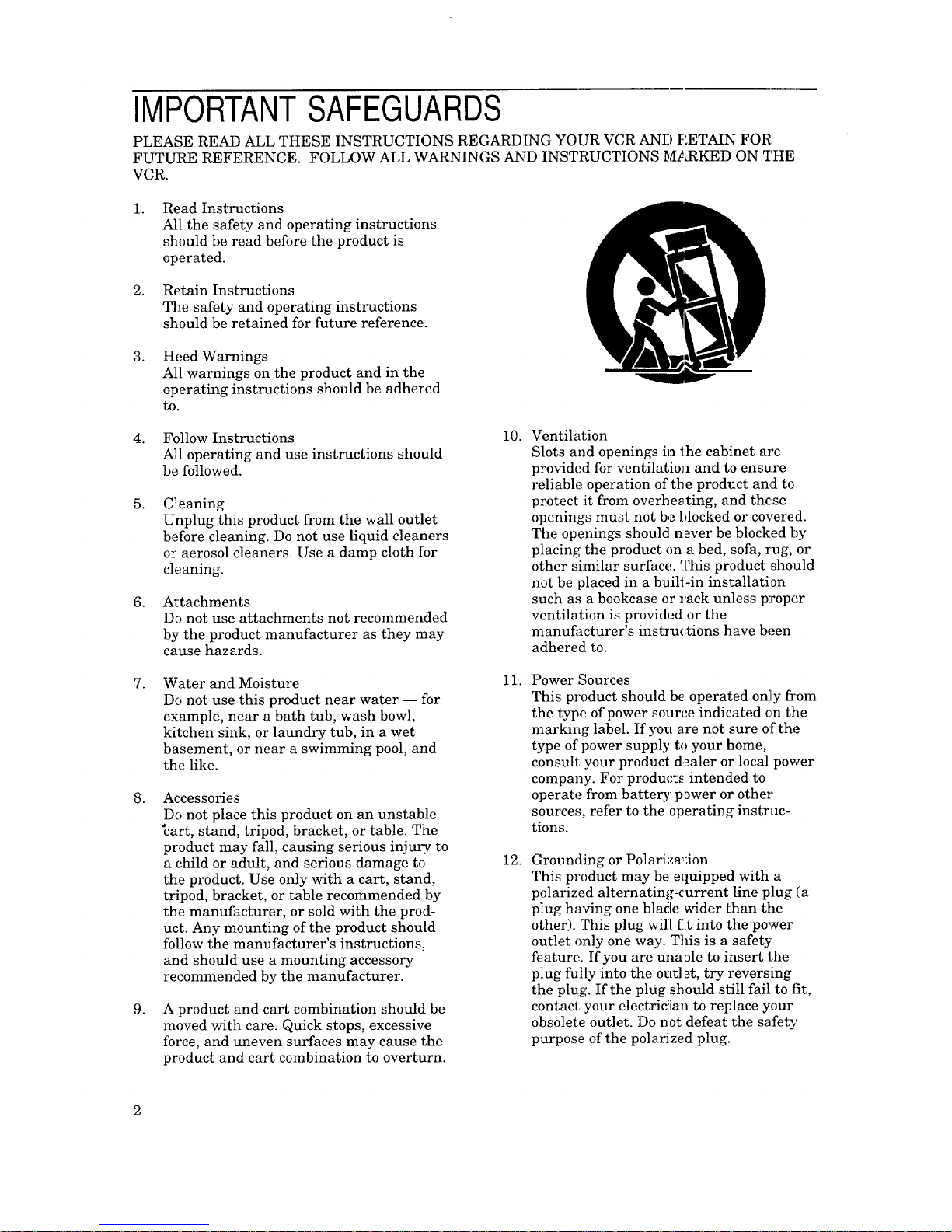
Accessories
Do not place this product on an unstable
"cart, stand, tripod, bracket, or table. The
product may fall, causing serious injury to
a child or adult, and serious damage to
the product. Use only with a cart, stand,
tripod, bracket, or table recommended by
the manufacturer, or sold with the prod-
uct. Any mounting of the product should
follow the manufacturer's instructions,
and should use a mounting accessory
recommended by the manufacturer.
A :product and cart combination should be
moved with care. Quick stops, excessive
force, and uneven surfaces may cause the
product and cart combination to overturn.
10.
11.
12.
Ventilation
Slots and openings in the cabinet are
provided for ventilatiol] and to ensure
reliable operation of the product and to
protect it from overheating, and th_se
openings must not be blocked or covered.
The openings should never be blocked by
placing the product on a bed, sofa, rug, or
other similar surface. This product should
not be placed in a built-in installation
such as a bookcase or rack unless proper
ventilation is provided or the
manufacturer's instructions have been
adhered to.
Power Sources
This product should be operated on][y from
the type of power source indicated on the
marking label. If you are not sure of the
type of power supply to your home,
consult your product d_aler or local power
company. For products intended to
operate from battery power or other
sources, refer to the operating instruc-
tions.
Grounding or Polariza_;ion
This product may be equipped with a
polarized alternating-current line plug (a
plug having one blade wider than the
other). This plug will f.lt into the power
outlet only one way. This is a safety
feature. If you are unable to insert the
plug fully into the outlet, try reversing
the plug. If the plug should still fail to fit,
contact :your electrician to replace your
obsolete outlet. Do not defeat the safety
purpose of the polarized plug.
13.
Power-CordProtection
Power-supplycordsshouldberoutedso
thattheyarenotlikely tobewalkedonor
pinchedbyitemsplaceduponoragainst
them,payingparticularattentiontocords
atplugs,conveniencereceptacles,andthe
pointwheretheyexitfromtheproduct.
14.
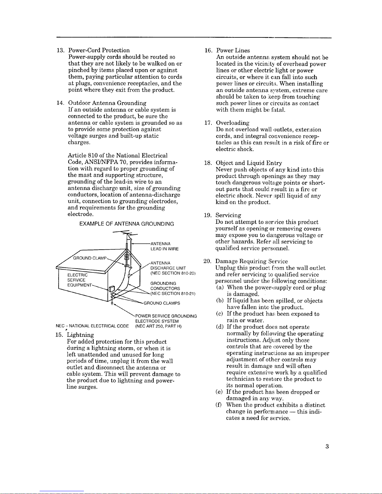
OutdoorAntennaGrounding
If anoutsideantennaorcablesystemis
connectedtotheproduct,besurethe
antennaorcablesystemisgroundedsoas
toprovidesomeprotectionagainst
voltagesurgesandbuilt-upstatic
charges.
Article810oftheNationalElectrical
Code,ANSUNFPA70,providesinforma-
tionwithregardtopropergroundingof
themastandsupportingstructure,
groundingofthelead-inwiretoan
antennadischargeunit, sizeofgrounding
conductors,locationofantenna-discharge
unit,connectiontogroundingelectrodes,
andrequirementsforthegrounding
electrode.
EXAMPLE OF ANTENNA GROUNDING
ANTENNA
LEAD IN WIRE
ANTENNA
DISCHARGE UNIT
(NEC SECTION 810-20)
GROUNDING
CONDUCTORS
(NEC SECTION 810-21)
GROUND CLAMPS
"_POWER SERVICE GROUNDING
ELECTRODE SYSTEM
NEC - NATIONAL ELECTRICAL CODE (NEC ART 250, PART H)
15. Lightning
For added protection for this product
during a lightning storm, or when it is
left unattended and unused for long
periods of time, unplug it from the wall
outlet and disconnect the antenna or
cable system. This will prevent damage to
the product due to lightning and power-
line surges.
16.
17.
18.
19.
20.
Power Lines
An outside antenna system should, not be
located in the vicinity of overhead power
lines or other electric light or power
circuits, or where it can fall into such
power lines or circuit_. When installing
an outside antenna system, extreme care
should be taken to :keep from touching
such power lines or circuits as contact
with them might be fatal.
Overloading
Do not overload wall outlets, exterLsion
cords, and integral convenience recep-
tacles as this can result in a risk of"fire or
electric shock.
Object and Liquid Entry
Never push objects of any kind into this
product through openings as they may
touch dangerous voltage points or short-
out par_s that could[ result in a fire or
electric shock. Never spill liquid of' any
kind on the product.
Servicing
Do not attempt to ser_Ace this product
yourself as opening or removing covers
may expose you to dangerous voltage or
other hazards. Refer all servicing to
qualified service personnel.
Damage Requiring ,Service
Unplug this product from the wall outlet
and refer servicing to qualified service
personnel under the fi)llowing conditions:
(a) When the pow.er-,mpply cord or plug
is damaged.
(b) If liquid has been spilled, or objects
have fallen intc the product.
(c) If the product has been exposed to
rain or water.
(d) If the product does not operate
n(n_nally by fol]iowing the operating
instructions. Adj_Lst only those
controls that are covered by the
operating instruclfions as an improper
adjustment of other controls may
result in dama_:e and will often
require extensive work by a qualified
teclhnician to restore the product to
its normal operation.
(e) If the product has been dropped or'
damaged in an}' way.
(f) When the product exhibits a distinct
change in performance -- this indi-
cates a need for service.

ImportantSafeguards
21.
22.
23.
Replacement Parts
When replacement parts are required, be
sure the service technician has used
replacement parts specified by the manu-
facturer or have the same characteristics
as the original part. Unauthorized substi-
tutions may result in fire, electric shock
or other hazards.
Safety Check
Upon completion of any service or repairs
to this product, ask the service technician
to perform safety checks to determine
that the product is in proper operating
coadition.
Heat
The product should be situated away from
heat sources such as radiators, heat
registers, stoves, or other products (in-
cluding amplifiers) that produce heat.
CONDENSATION
Leave the VCR on, without a tape in it, for 2
hours if the VCR has been exposed to sudden
changes in temperature. Sudden temperature
changes cause moisture to form on the metal
parts inside the VCR. This moisture can cause
the tape to stick and damage the head.
Leaving the VCR on for a 2 hour period will
dry the inside of the VCR.
PROTECTTHE POWERCORD
Do not damage the power cord. Damage to the
power cord may cause a fire or shock hazard.
When unplugging the pc w,_r cord, pleaE=e hold
it by the plug and remove !:t carefully.
DONOT PLACEHEAVYOBJECTSON THE
RECORDER
Heavy objects placed on the recorder will
cause damage. (This does not mean your cable
box). The top of the recorder is also slotted to
provide venlLilation. Do _ot obstruct these
ventilation ,;lots.
WHENNOT IN USE
V_Len you finish operating the recorder,
always unload the cassette and turn OFF the
VCR POWER.
CAREOFTHE VIDEOCASSETTETAPES
• Avoid violent vibration or shock.
• Do not place in a locar.ien where strong
magnetic fields exist (near a motor, trans-
former or magnet).
• Never place or store in direct sunlight.
• Avoid dusty places.
• Place the cassette in the cassette case and
store vertically.
• :Never store tape in a ihi_,_hhumidity :loca-
tion.
INFORMATION
This equipment has been tested and found to comply witch the limits for a Class B digital device,
pursuant to Part 15 of the FCC Rules. These limits are designed to provide reasonable protection
against harmful interference in a residential installation. This equipment generates, uses, and
can radiate radio frequency energy and, if not installed and used in accordance with the instruc-
tions, may cause harmful interference to radio communications. However, there is no guarantee
that interference will not occur in a particular installation. If thi s equipment do,_s cause harmful
interference to radio or television reception, which can be determined by turning the equipment
off and on, the user is encouraged to try to correct the interference by one or more of the following
measures:
• Reorient or relocate the receiving antenna;
• Increase the separation between the equipment and receiver;
• Connect the equipment into an outlet on a circuit different from that to which the
receiver is connected;
• Consult the dealer or an experienced radio/TV technician for help.
Changes or modifications not expressly approved by the party responsible for co:_apliance could
void the user's authority to operate the equipment.
If necessary, the user should consult the dealer or an experienced radio/television technician for
additional suggestions. The user may find the following booklet prepared by the Federal Commu-
nications Commission helpful:
"How to Identify and Resolve Radio-TV Interference Problems."
This booklet is available from the US Government Printing Office, Washington, D.C., 20402,
Stock No. 004-000-00345-4.
4
,_PREFACE
Welcometo Mitsubishi
Congratulations on your purchase of this Mitsubishi Video
Cassette Recorder. Your new VCR produces superior sound and
the highest quality S-VHS picture. It includes VHS Hi-Fi audio
recording and playback, delivering compact disc-quality audio.
Your VCR also includes the VCR Plus+ system and converter box
control for simplified programming.
Your owner's guide has been designed with easy-to-follow expla-
nations and directions. In addition, your VC,R comes with
Mitsubishi's exclusive _'on-screen ope]_al;ing system. This
system has been developed to simplify the operation of your VCR
with clear, understandable language and desi,_n.
Thank you for selecting our product and welcome to Mitsubishi.
UnpackingYourVCR
Remote control
ooo0
8o 8
0 ®
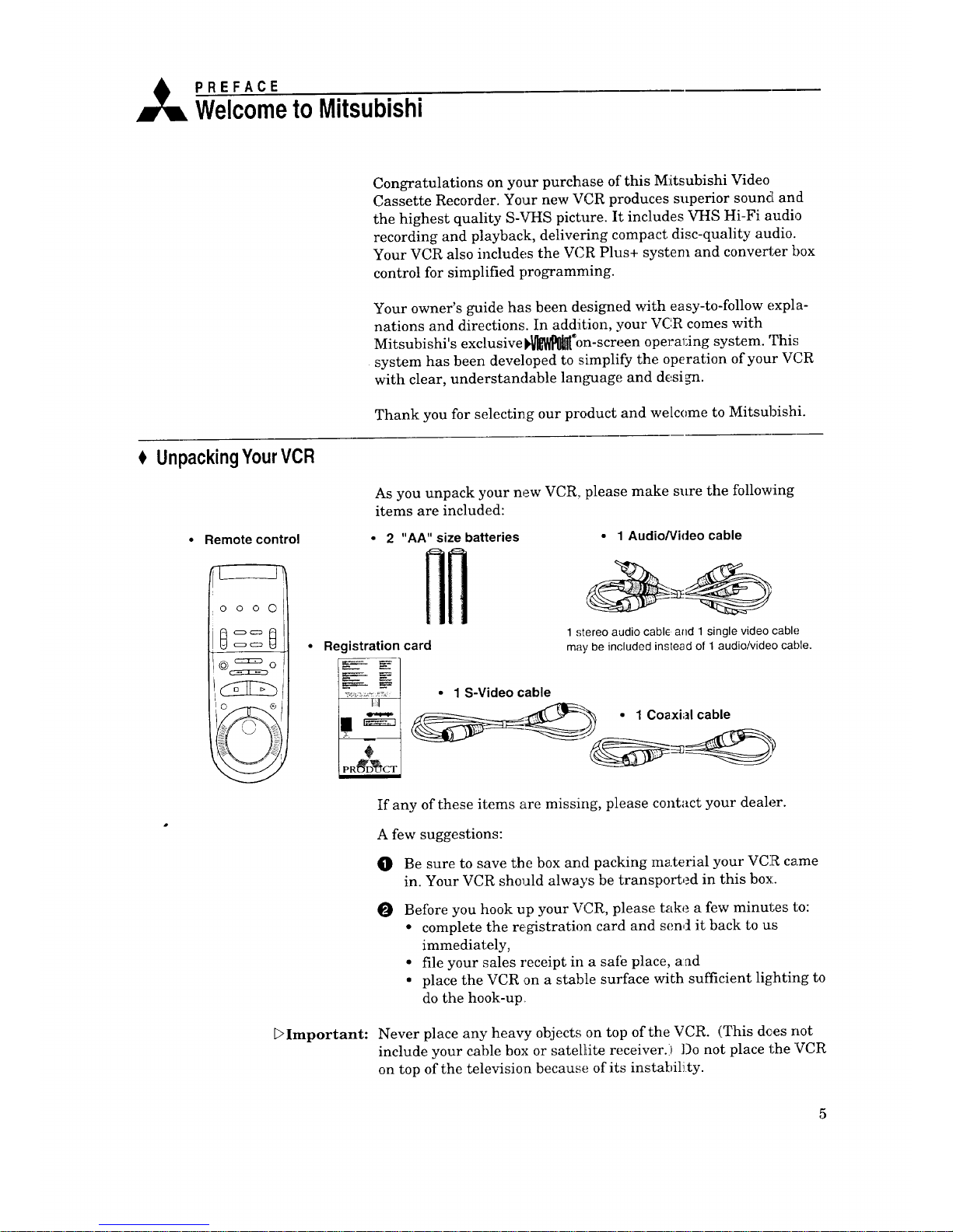
As you unpack your new VCR, please make sure the following
items are included:
• 2 "AA" size batteries
Registration card
i:ii
• 1 Audio/Video cable
1 stereo audio cable and 1 single video cable
may be included instead of 1 audio/video cable.
• 1 S-Video cable
If any of these items are missing, please contact your dealer.
A few suggestions:
O
O
Be sure to save the box and packing material your VCR came
in. Your VCR should always be transported in this box.
Before you hook up your VCR, please take a few minutes to:
• complete the registration card and send it back to us
immediately,
• file your sales receipt in a safe place, a:ad
• place the VCR on a stabile surface with sufficient lighting to
do the hook-up
DImportant: Never place any heavy objects on top of the VCR. (This de,es not
include your cable box or satellite receiver.) Do not place the VCR
on top of the television because of its instability.
5
Ge t ng ol nowYourVCR
Now that you have unpacked your player and read through the
safety information, it's time to become familiar with the buttons
and controls.
If you are experienced with using VCRs, you may just want to
glance at this section and refer to it later. IfVCRs are new to you,
you may want to take your time and become familiar with the
locations of all the controls.
On the following pages, you'll find information on:
$ Front PanelButtonsand Functions
FluorescentDisplay
Overviewof the RemoteControl
$ Rear PaneITerminals
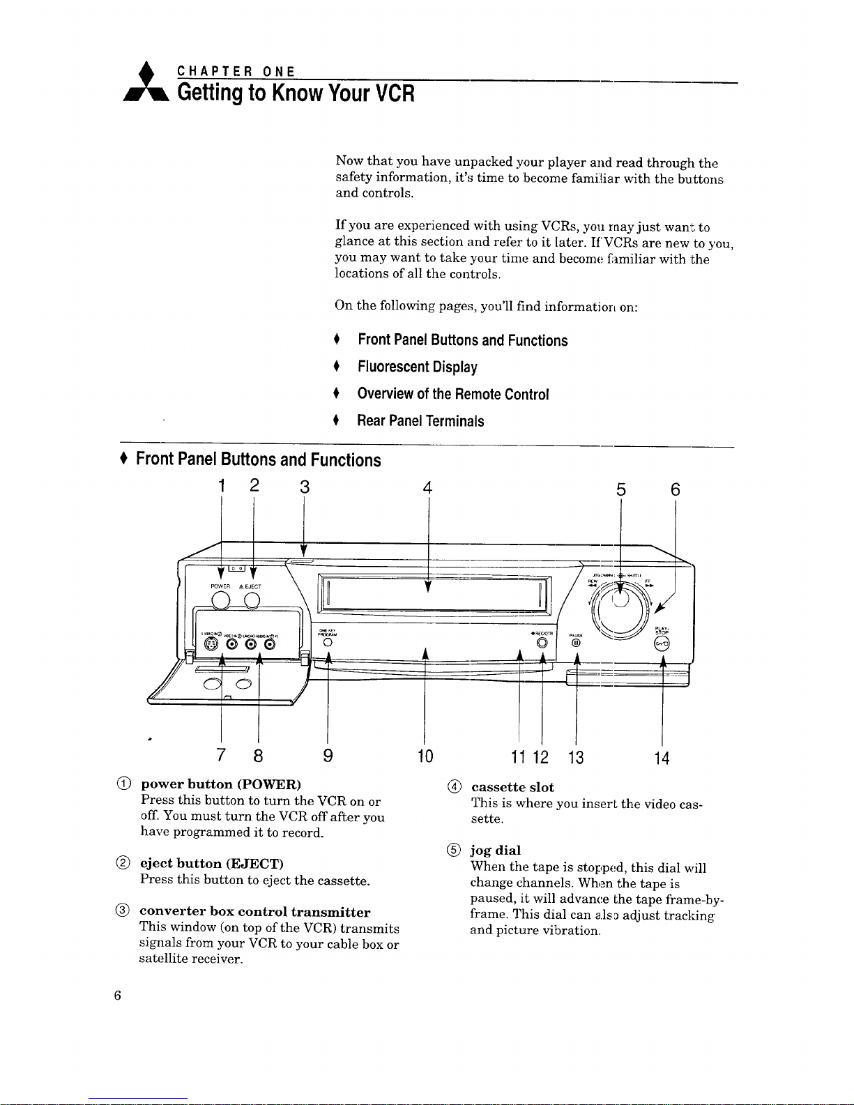
FrontPanelButtonsandFunctions
Q
®
®
1 2 3
7 8 9
4
5 6
10 11 12 13 14
power button (POWER)
Press this button to turn the VCR on or
off. You must turn the VCR off after you
have programmed it to record.
eject button (EJECT)
Press this button to eject the cassette.
converter box control transmitter
This window (on top of the VCR) transmits
signals from your VCR to your cable box or
satellite receiver.
(_) cassette slot
This is where you insert the video cas-
sette.
®
jog dial
When the tape is stopped, this dial will
change channels. When the tape is
paused, it will advance [he tape frame-by-
frame. This dial can als_ adjust tracking
and picture vibration.
®
©
®
®
shuttle ring
Turn this ring to the right to fast forward
a tape or to fast forward search. Turn this
ring to the left to rewind a tape or to
reverse search.
video input 2 terminals
If you want to record or dub video from
another source (such as a VCR or
camcorder), you plug the source in here.
audio input 2 terminals
If you want to record or dub audio from
another source (such as a VCR or
camcorder), you plug the source in here.
one key program button
(ONE KEY PROGRAM)
By pressing this button, you may use one
of the methods of programming your VCR
to record.
@) fluorescent display
See the next section.
@
@
@
@
remote control sensor
This receives signals from the remote
control. Do not block it.
record button (REC/OTR)
Press this button once to record until the
end of the tape. Press repeatedly to set the
time for One-Touch Recording (OTR).
pause button (PAUSE)
Press this button to pause a tape w:hen
recording, or to freeze a frame when
viewing a tape.
play and stop button (PLAY/STOP)
Press this button to play a tape and press
again to stop the tape. Also press to stop
tape related functions or to resume normal
playback from special effects.
FluorescentDisplay
1 2 3 45
AM PM SU MO TU WE TH FRD SA • SAP ST|
_IIZI•ElI-_IFIrl•rlrlrl
IU U.U I_1
'\ /'\
12
78
SI_@'
_SPEl
PT VCR
I J-I
13 14
10 11
_ [] dBN
15
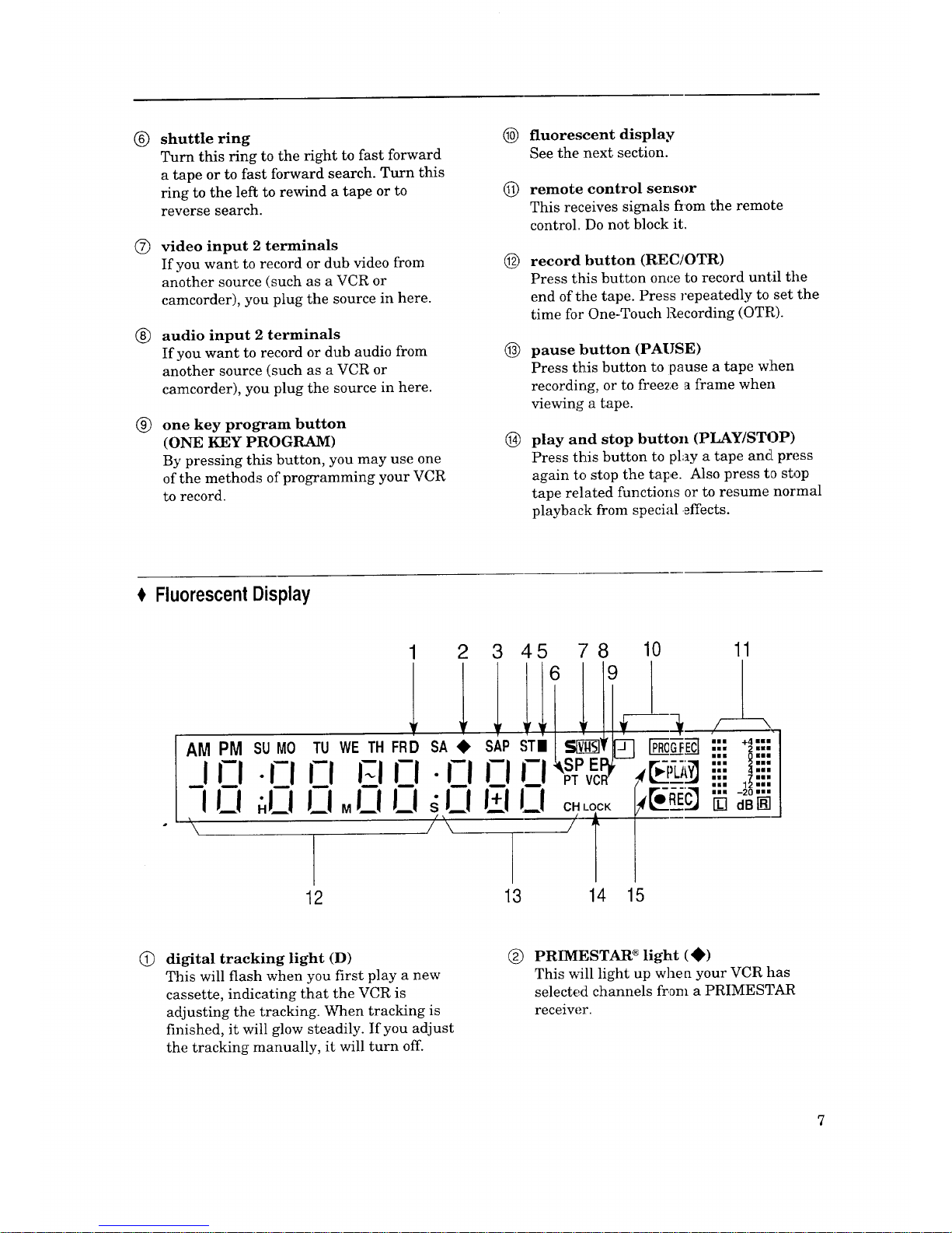
digital tracking light (D)
This will flash when you first play a new
cassette, indicating that the VCR is
adjusting the tracking. When tracking is
finished, it will glow steadily. If you adjust
the tracking manually, it will turn off.
® PRIMESTAR * light (•)
This will light up whe a your VCR has
selected channels from a PRIMESTAR
receiver.
7
Chapter1:GettingtoKnowYourVCR FluorescentDisplay(cont)
®
Q
®
®
®
®
®
®
©
SAP indicator (SAP)
This will light up to indicate that the
channel you are watching has a Separate
Audio Program, or S.A.P. An S.A.P. is an
alternative soundtrack to the program you
are watching. The S.A.P. is often another
language.
stereo indicator (ST)
This lights up when the VCR is receiving a
stereo TV channel.
cable tuning light ( • )
This lights up when your VCR is receiving
cable broadcasts.
PerfecTape ®light (PT)
This will flash when the PerfecTape test is
in progress. It will stay illuminated when
the test is completed.
S-VHS indicator (S-VHS)
This will light up when you play or record
in Super-VHS (S-VHS).
tape speed lights (SP, EP)
This will light to indicate the tape speed
you are using when playing or recording.
"SP" indicates standard play; "EP" indi-
cates extended play.
VCR light (VCR)
This will light up when the VCR/TV
button is set to "VCR." It indicates that
the picture is controlled by the VCR.
programmed recording light (P7 [_)
This lights up when the VCR is off and
you have programmed the VCR to record.
peak level meters
This displays the audio level in decibels
for both the left (L) and right (R) channels.
@
@
®
@
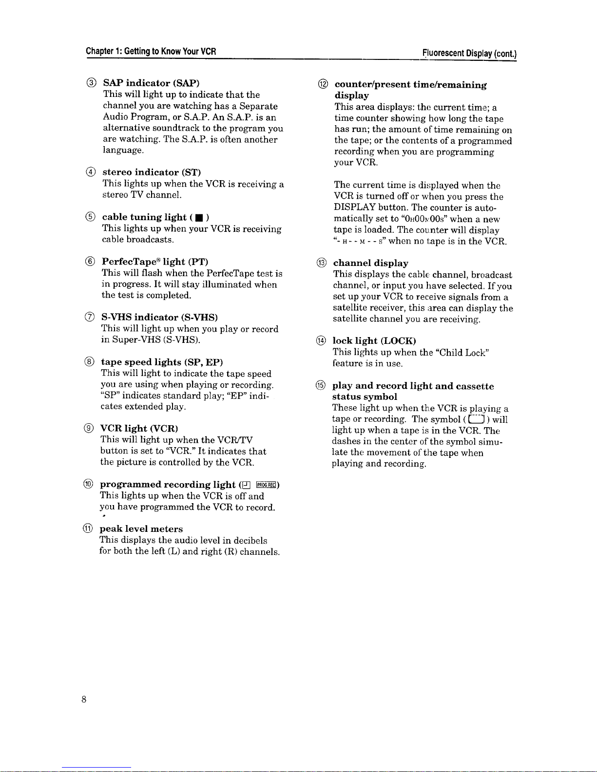
counter/present time/remaining
display
This area displays: t;he current time; a
time counter showing how long the tape
has run; the amount; of time remaining on
the tape; or the contents of a programmed
recording when you are programming
your VCR.
The current time is displayed when the
VCR is turned offor when you press the
DISPLAY button. The counter is auto-
matically set to "0H00_00S" when a new
tape is loaded. The counter will display
"- H- - M- - S" when no tape is in the VCR.
channel display
This displays the cable, channel, broadcast
channel, or input you have selected. If you
set up your VCR to receive signals from a
satellite receiver, this area can display the
satellite channel you ace receiving.
lock light (LOCK)
This lights up when the "Child Lock"
feature is in use.
play and record light and cassette
status symbol
These light up when the VCR is playing a
tape or recording. The symbol ( [-"_J ) will
light up when a tape is in the VCR. The
dashes in the center of the symbol simu-
late the movement of the tape when
playing and recording.
Overviewofthe RemoteControl
Q
®
®
1
2-
.m
.
.__
6--
7-
8
.__
10--
11
--12
13
--14
15
16
17
18
--19
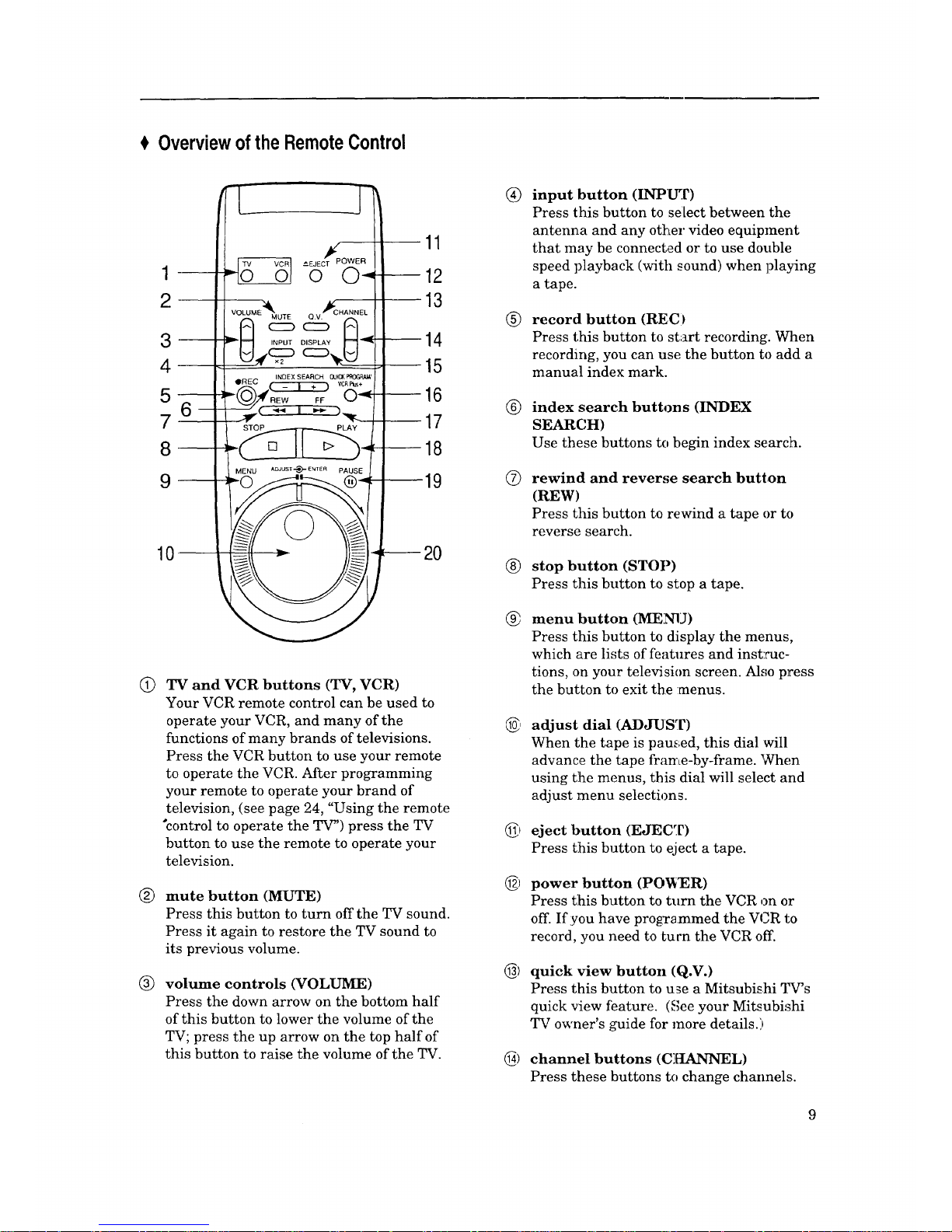
TV and VCR buttons (TV, VCR)
Your VCR remote control can be used to
operate your VCR, and many of the
functions of many brands of televisions.
Press the VCR button to use your remote
to operate the VCR. After programming
your remote to operate your brand of
television, (see page 24, "Using the remote
"control to operate the TV') press the TV
button to use the remote to operate your
television.
mute button (MUTE)
Press this button to turn off the TV sound.
Press it again to restore the TV sound to
its previous volume.
volume controls (VOLUME)
Press the down arrow on the bottom half
of this button to lower the volume of the
TV; press the up arrow on the top half of
this button to raise the volume of the TV.
®
®
®
O
®
®
6)
6)
6)
6)
input button (INPUT)
Press this button to select between the
antenna and any other video equipment
that may be connected or to use double
speed playback (with sound) when ])laying
a tape.
record button (REC)
Press this button to start recording. When
recording, you can use the button to add a
manual index mark.
index search buttons (INDEX
SEARCH)
Use these buttons to begin index search.
rewind and rever,_e search button
(REW)
Press this button to rewind a tape or to
reverse search.
stop button (STOP)
Press this button to stop a tape.
menu button (MENU)
Press this button to display the menus,
which are lists of features and inst:cuc-
tions, on your television screen. Also press
the button to exit the :menus.
adjust dial (ADJUST)
When the tape is pau_ged, this dial will
advance the tape frame-by-frame. When
using the menus, this dial will select and
adjust menu selections.
eject button (EJECT)
Press this button to eject a tape.
power button (POWER)
Press t:his button to turn the VCR on or
off. If you have programmed the V ,R to
record, you need to turn the VCR off.
quick view button (Q.V.)
Press this button to use a Mitsubishi q.W's
quick view feature. (See your Mitsubishi
TV owner's guide for more details.)
channel buttons (C][tANNEL)
Press these buttons to change channels.
Chapter1:GettingtoKnowYourVCR OverviewoftheRemoteControl(cont.)
®
®
@
@
@
®
@
@
display button (DISPLAY)
Press this button to display the following
infbrmation on the television:
• how much time has elapsed on the
current tape,
• the channel number and the audio
reception mode you are watching,
• the audio channel(s) you selected,
• the source that is supplying the VCR
with a signal,
• the present time,
• whether the VCR is stopped, playing,
or recording, and
• how much time is left on the tape.
This button can also be used to turn on
and off the "Child Lock" feature.
quick program and VCR Plus+ ®
button (QUICK PROGRAM/
VCR Plus+)
This button allows you to program your
VCR more quickly and easily. When you
press this button, you will immediately
see the "Program to record" screen, where
you can enter a PlusCode programming
number or begin programming your VCR
to record.
fast forward and fast forward search
button (FF)
Press this button to fast forward a tape or
to fast forward search.
play button (PLAY)
Press this button to play a tape.
pause button (PAUSE)
Press this button to pause a tape when
recording or to freeze a frame when
viewing a tape.
shuttle ring
When a tape is playing, turn this ring to
adjust the playback speed. When using
the menus, turn this ring to enter or
cancel selections.
mode buttons (VCR-A, VCR-B)
Use these buttons to operate two Mitsu-
bishi VCRs with one remote. (See page 23.)
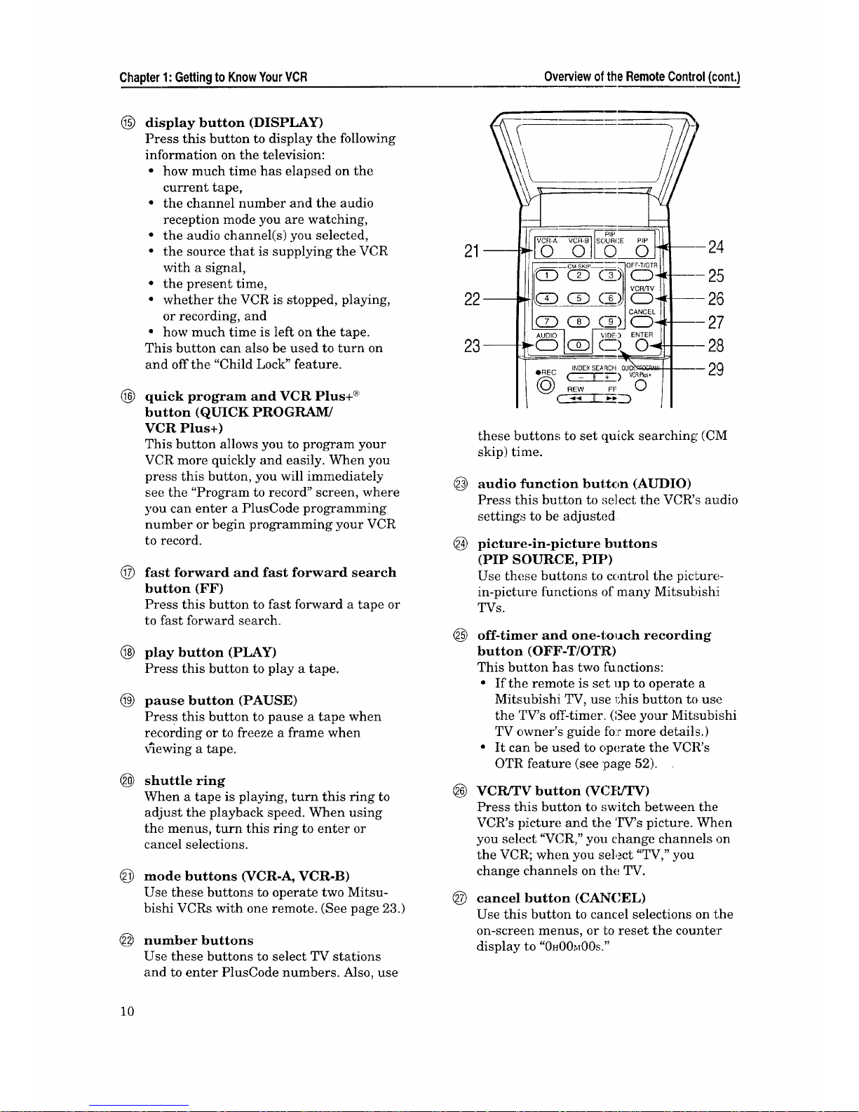
number buttons
Use these buttons to select TV stations
and to enter PlusCode numbers. Also, use
10
@
@
@
®
@
5
---2,4.
--- 25
---26
--- 27
---28
- 29
these buttons to set quick searching (CM
skip) time.
audio function button (AUDIO)
Press this button to select the VCR's audio
settings to be adjusted
picture-in-picture buttons
(PIP SOURCE, PIP)
Use these buttons to control the picture-
in-picture functions of many Mitsubishi[
TVs.
off-timer and one-tolJch recording
button (OFF-T/OTR)
This button has two fuactions:
• If the remote is set up to operate a
Mitsubishi TV, use 1;his button to use
the TV's off-timer. (See your Mitsubishi
TV owner's guide fo:r more details.)
• It can be used to operate the VCR's
OTR feature (see :page 52).
VCR/TV button (VCFJIW)
Press this button to switch between the
VCR's picture and the TV's picture, when
you select '_VCR," you change channels on
the VCR; when you select "TV," you
change channels on the TV.
cancel button (CANCEL)
Use this button to cancel selections on the
on-screen menus, or to reset the counter
display to "0H00M00S."
@ enter button (ENTER)
Use this button to enter selections on the
on-screen menus.
(_ video function buttorL (VIDEO)
Press this button to select the VCR's video
settings to be adjusted.
RearPanelTerminals
@
®
®
®
®
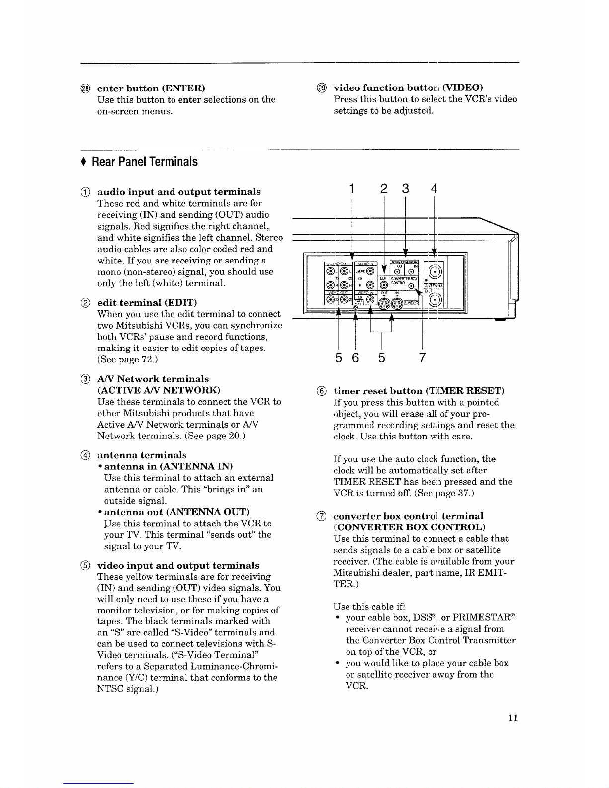
audio input and output terminals
These red and white terminals are for
receiving (IN) and sending (OUT) audio
signals. Red signifies the right channel,
and white signifies the left channel. Stereo
audio cables are also color coded red and
white. If you are receiving or sending a
mono (non-stereo) signal, you should use
only the left (white) terminal.
edit terminal (EDIT)
When you use the edit terminal to connect
two Mitsubishi VCRs, you can synchronize
both VCRs' pause and record functions,
making it easier to edit copies of tapes.
(See page 72.)
A/V Network terminals
(ACTIVE A/V NETWORK)
Use these terminals to connect the VCR to
other Mitsubishi products that have
Active A/V Network terminals or A/V
Network terminals. (See page 20.)
antenna terminals
• antenna in (ANTENNA IN)
Use this terminal to attach an external
antenna or cable. This "brings in" an
outside signal.
• antenna out (ANTENNA OUT)
JJse this terminal to attach the VCR to
your TV. This terminal "sends out" the
signal to your TV.
video input and output terminals
These yellow terminals are for receiving
(IN) and sending (OUT) video signals. You
will only need to use these if you have a
monitor television, or for making copies of
tapes. The black terminals marked with
an "S" are called "S-Video" terminals and
can be used to connect televisions with S-
Video terminals. ("S-Video Terminal"
refers to a Separated Luminance-Chromi-
nance (Y/C) terminal that conforms to the
NTSC signal.)
1 2 3 4
5 6 5 7
®
®
timer reset button (T][MER RESt::T)
If you press this button with a pointed
object, you will erase all of your pro-
j_ammed recording settings and reset the
clock. Use this button with care.
If you use the auto clock function, the
clock will be automatically set after
TIMER RESET has been pressed and the
VCR is turned off. (See page 37.)
converter box contro]L terminal
(CONVERTER BOX CONTROL)
Use this terminal to connect a cable that
sends si_,mals to a cab:[e box or satellite
receiver. (The cable is available from your
Mitsubishi dealer, part name, IR EMIT-
TER.)
Use this cable if:
• your cable box, DSS% or PRIMESTAR ®
receiver cannot receive a signal from
the Converter Box Control Transmitter
on top of the VCR, or
• you would like to place your cable box
or satellite receiver away from the,
VCR.
11
Chapter2:ConnectingYourVCR ConnectingtheAntennaor(::abletotheVC£(cont.)
Insert lead under screws
and tighten.
300-75 Ohm Adapter
VCR Back
Panel
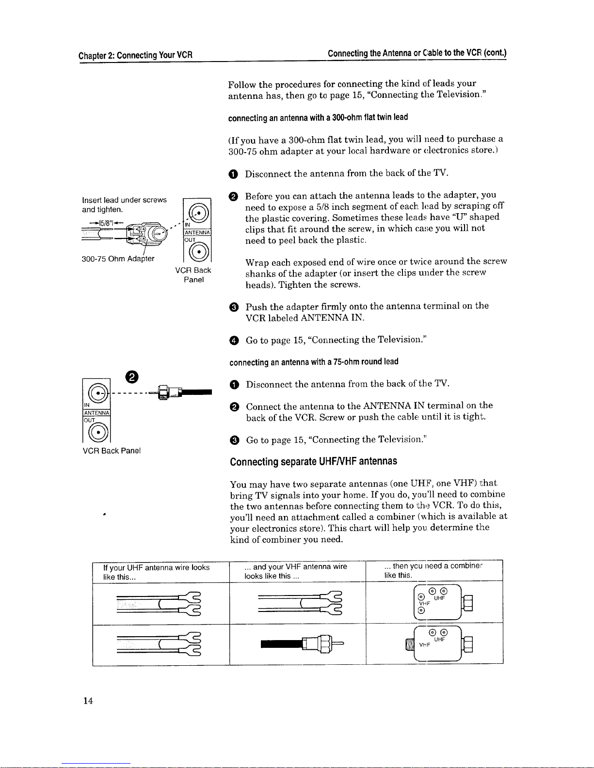
Follow the procedures for connecting the kind of leads your
antenna has, then go to page 15, "Connecting the Television."
connectinganantennawitha300-ohmflattwinlead
(If you have a 300-ohm flat twin lead, you will need to purchase a
300-75 ohm adapter at your local hardware or electronics store )
O Disconnect the antenna from the back of the TV.
O Before you can attach the antenna leads to the adapter, you
need to expose a 5/8 inch segment of each lead by scraping off
the plastic covering. Sometimes these leads have "U" shaped
clips that fit around the screw, in which case you will not
need to peel back tile plastic.
O
Wrap each exposed end of wire once or twice around the screw
shanks of the adapter (or insert the clips under the screw
heads). Tighten the screws.
Push the adapter firmly onto the antenna terminal on the
VCR labeled ANTENNA IN.
O Go to page 15, "Connecting the Television."
connectinganantennawitha75-ohmroundlead
q[]) Disconnect the antenna from the back of the TV.
O Connect the antenna to the ANTENNA IN terminal on the
back of the VCR. Screw or push the cable until it is tighL
Go to page 15, "Connecting the Television."
ConnectingseparateUHFNHF antennas
You may have two separate antennas (one UHF, one VHF) l_hat
bring TV signals into your home:. If you do, you'll need to combine
the two antennas before connecting them to 1;heVCR. To do thi%
you'll need an attachment called a combiner (_hich is available at
your electronics store). This chart will help you determine the
kind of combiner you need.
If your UHF antenna wire looks ... and your VHF antenna wire
like this.., looks like this ...
... then ycu need a combiner
likethis.
14
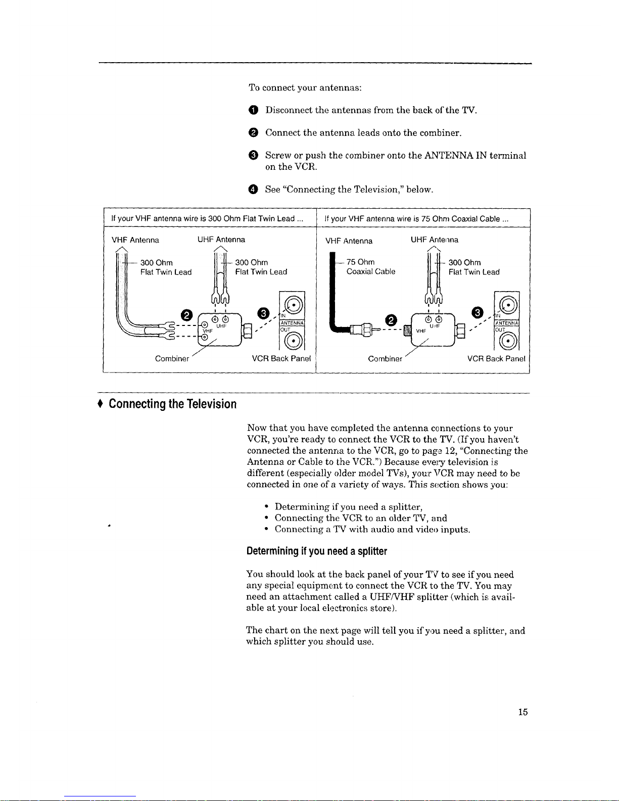
To connect your antennas:
O Disconnect the antennas from the back of the TV.
O Connect the antenna leads onto the combiner.
O Screw or push the combiner onto the ANTENNA IN te_ninal
on the VCR.
O See "Connecting the Television," below.
If your VHF antenna wire is 300 Ohm Flat Twin Lead ... If your VHF antenna wire is 75 Ohm Coaxial Cable ...
VHF Antenna UHF Antenna
6, A
_ 3F00Ohm Lead _ 30a0tOwhmLead
Iitl @ : ',
/
Combiner
VHF Antenna
75 Ohm
Coaxial (,'able
VCR Back Panel ,
UHF Antenna
/'\
i
/
Combiner
300 Ohm
Flat Twin Lead
VCR Back Panel
Connecting theTelevision
Now that you have completed the antenna connections to your
VCR, you're ready to connect the VCR to the TV. (If you haven't
connected the antenna to the VCR, go to page 12, "Connecting the
Antenna or Cable to _he VCR.") Because every television is
different (especially older model TVs), your VCR may need to be
connected in one of a variety of ways. This section shows you:
• Determining if you need a splitter,
• Connecting the VCR to an older TV, and
• Connecting a TV with audio and video inputs.
Determiningif you need a splitter
You should look at the back panel of your _Fq to see if you need
any special equipment to connect the VCR to the TV. You may
need an attachment called a UHF!VHF splitter (which is awtil-
able at your local electronics store).
The chart on the next page will tell you if you need a splitter, and
which splitter you should use.
15
Chapter2:ConnectingYourVCR Connectingthe Television(cont.)
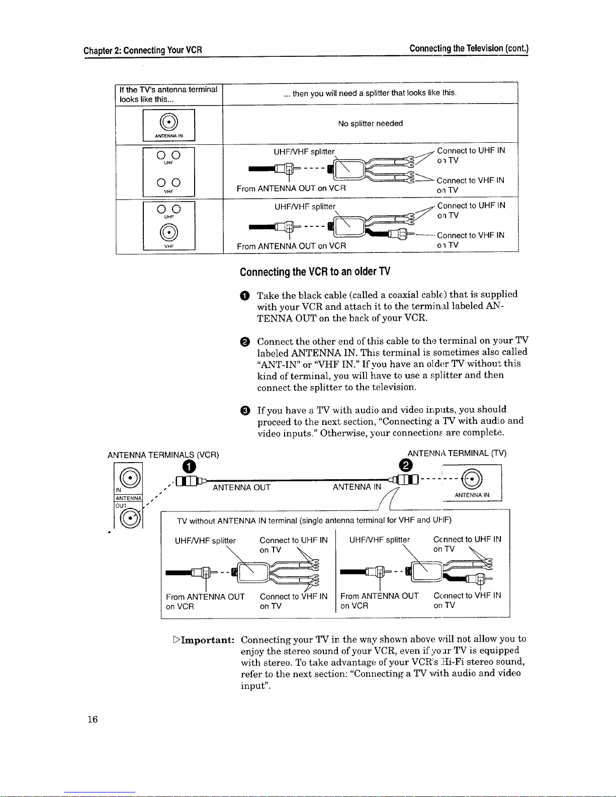
Ifthe"l-V'santennaterminal ...thenyouwillneeda splitterthatlookslikethis.
lookslikethis...
®
ANTENNA IN
GO
UHF
O©
VHF
O©
UHF
®
VNF
No splitter led
UHF/VHF splitter _,
From ANTENNA OUT on VC:R
Connect to UHF IN
o_ TV
Connect to VHF IN
on TV
UHFNHF splitter
From ANTENNA OUT on VCR
Connect to UHF IN
on-rV
Connect to VHF IN
o_TV
Connectingthe VCR to an olderTV
O Take the black cable (called a coaxial cable) that is supplied
with your VCR and attach it to the terminal labeled AN-
TENNA OUT on tile back of your VCR.
O
Connect the other end of this cable to the terminal on your TV
labeled ANTENNA IN. This terminal is sometimes also called
"ANT-IN" or "VHF IN." If you have an older TV without th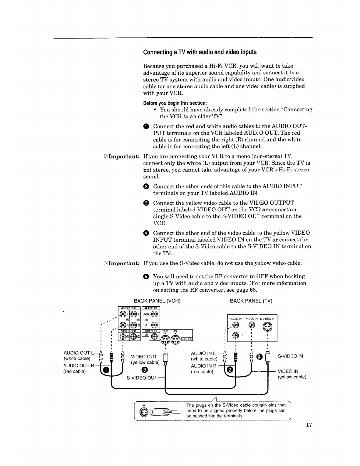
ConnectingaTV with audioandvideo inputs
_Important:
_Important:
Because you purchased a Hi-Fi VCR, you _4L want to take
advantage of its superior sound capability and connect it to a
stereo TV system with audio and video inputs. One audio/video
cable (or one stereo audio cable and one vid[eo cable) is supplied
with your VCR.
Beforeyou begin this section:
• You should have already completed 1;he section "Connecting
the VCR to an older TV".
O
Connect the red and white audio cables to the AUDIO OUT-
PUT terminals on the VCR labeled AUDIO OUT. The red
cable is for connecting the right (R) channel and the white
cable is for connecting the left (L) channel.
If you are connecting your VC,R to a mono (non-stereo) TV,
connect only the white (L) output from your VCR. Since the TV is
not stereo, you cannot take advantage of your VCR's Hi-FJ stereo
sound.
Connect the other ends of this cable to the AUDIO IN]?UT
terminals on your TV labeled AUDIO IN.
Connect the yellow video cable to the VIDEO OUTPUT
terminal labeled 'VIDEO OUT on the VCR or connect an
single S-Video cable to the S-VIDEO O_? terminal on the
VCR.
O Connect the other end of the video cable to the yellow VIDEO
INPUT terminal labeled VIDEO IN on the TV or connect the
other end of the S-Video cable to the S-V]DEO IN terminal on
the TV.
If you use the S-Video cable, do not use the yellow video cable.
You will need to set the RF converter to OFF when hooking
up a TV with audio and video inputs. (Fo:r more information
on setting the RF converter, see page 68.)
BACK PANEL (VCR)
AUDIO OUT L-- _,
(white cable)
AUDIO OUT R -
(red cable)
I
._ VIDEO OUT
(yellow cable)
0
S-VIDEO OUT--
BACK PANEL (TV)
AUDIO IN
R
AUDIO IN L ---i_
(whitecable) ?
AUOIO IN R -_
(red cable) _
u
VIDE() IN S-VIDEO IN
!
i
_j_,..
-- S-VIDI--O IN
-- VIDEO IN
(yellow cable)
A
The plugs on the S-Video cable contain pins that
need to be aligned properly befo,'e the plugs can
Jbe pushed into the terminals.
17
Chapter2:ConnectingYourVCR
Connectinga DSS or PRIMESTAWReceiver(optional)
18
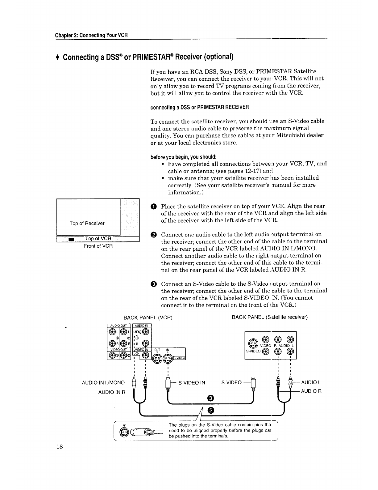
If you have an RCA DSS, Sony DSS, or PRIMESTAR Satellite
Receiver, you can connect the receiver to your VCR. This will not
only allow you to record TV programs coming from the receiver,
but it will allow you to control the receiver with the VCR.
connectinga DSSorPRiMESTARRECEIVER
To connect the satellite receiver, you should tLSe an S-Video cable
and one stereo audio cable to preserve the m_ximum signal
quality. You can purchase these cables at your Mitsubishi dealer
or at your local electronics store.
Top of Receiver
== Top of VCR
Front of VCR
before you begin, you should:
• have complete(] all connections between your VCR, TV, and
cable or antenna; (see pages 12-17) and
• make sure that your satellite receiver has been installed
correctly. (See your satellite receiver's manual for more
information.)
O Place the satellite receiver on top of your VCR. Align the rear
of the receiver with the rear of the VCR and align the left side
of the receiver with the left side of the VCR.
O
Connect one audio cable to the left audio output terminal ,on
the receiver; corm ect the other end of the cable to the terminal
on the rear panel of the VCR labeled AUDIO IN I_AVIONO.
Connect another audio cable to the right output terminal on
the receiver; connect the other end of this cable to the termi-
nal on the rear panel of the VCR labeled AUDIO IN R
O
Connect an S-Video cable to the S-Video output terminal on
the receiver; connect the other end of the cable to the terminal
on the rear of the VCR labeled S-VIDEO :IN. (You cannot
connect it to the terminal on the front cfthe VCR.)
BACK PANEL(VCR)
BACK PANEL (Satellite receiver)
l
l
i I
AUDIO IN IJMONO --
AUDIO IN R --
I •
t S-VIDEO IN S-VIDEO
O
/// O ._..
The plugs on the S-Video cable contain pins thaL ]
need to be aligned properly before the plugs can
Jbe pushed into the terminals.
-- AUDIC) L
- --ALJDIO R
=#
E>Important:
If possible, you should have connected your VCR to your IW with
an S-Video cable. Not only will this provide you with a better
picture, but it will allow you to watch the sal;ellite video signal on
your TV even when the VCR is off. (When the auto clock function
(on pages 36-38) works to set the clock, you cannot watch the
satellite video signal.) If you connect your VCR to your TV with a
standard video cable, you will have to turn your VCR on to watch
the video signal from the satellite receiver. (You will be able to
hear the audio signal[ from your satellite receiver both when the
VCR is on and when it is off.)
If you want to connect a cable box with audio/video outputs to
your VCR, connect it to the terminals on the front of the VCR.
When you connect a satellite receiver to the ,_-Vldeo'_" inpul; on the
rear of the VCR, you cannot record through the standard video
input on the rear of the VCR.
_>Important:
After you have connected the satellite receiw_r and completed the
"AllSet" procedure (o:a pages 28-33), you need to see if your VCR
can control your receiver. To do this, use the CHANNEL buttons
or number buttons on the VCR remote to t-nne to a satellite
channel. If the satellite channels appear on your TV, then your
VCR can control your receiver. If it does not_ try repositioning or
moving the Satellite receiver. If they still do a't appear, you will
need to obtain an IR emitter (part name: IR EMITTER) from your
Mitsubishi dealer.
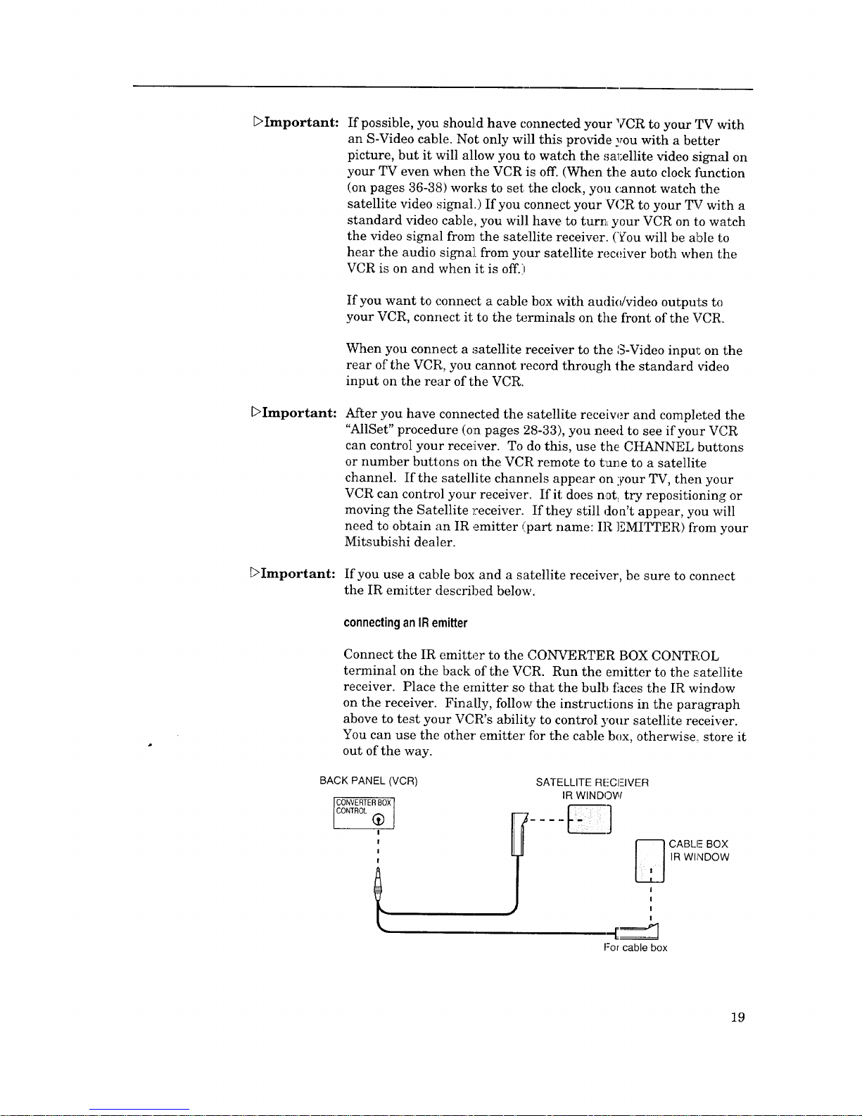
DImportant: If you use a cable box and a satellite receiver, be sure to connect
the IR emitter described below.
connectinganIRemitter
Connect the IR emitter to the CONVERTER BOX CONTt_:OL
terminal on the back of the VCR. Run the emitter to the satellite
receiver. Place the emitter so that the bulb fi_ces the IR window
on the receiver. Finally, follow the instructions in the paragraph
above to test your VCR's ability to control your satellite receiver.
You can use the other emitter for the cable box, otherwise: store it
out of the way.
BACK PANEL (VCR)
CONVERTERBOX
CONTROL (_)
SATELLITE RE-CI--IVER
IR WINDOW
I
I
I
I
For cable box
CABLE BOX
IR WINDOW
19

Chapter2:ConnectingYourVCR
# ConnectingtheAN Network(optional)
2O
(Other
Some Mitsubishi TVs and VCRs have special input and output
terminals called the "A/V Network." The pArnary purpose of the
A/V Network is to "pass" remote control codes between Mitsubishi
components. That is, when the A/V Network is connected, you can
point your VCR remote control at the TV, and the TV will "pass"
the commands on to the VCR.
To connect the A/V Network, you will need a cable with a "mini"
jack at both ends. (A mini jack is the kind yoa find on headphones
for personal stereos.) A cable may be included with your Mitsu-
bishi TV. If not, you can purchase a cable with mini jacks at your
Mitsubishi dealer or an electronics store. To connect the PJV
Network:
O
Connect a cable to the terminal on the TV labeled A/V NET-
WORK OUT or ACTIVE A/V NETWORE:. Connect the other
end of the cable to the terminal on the VCR labeled ACTIVE
A/V NETWORK :[N.
O
If you have another Mitsubishi component equipped with A/V
Network, attach a cable to the terminal en the VCR labeled
ACTIVE A/V NETWORK OUT. Attach the other end of this
cable to the terminal on the other component labeled _JV
NETWORK IN or ACTIVE A/V NETWORK IN.
BACK PANEL
Mitsubishicom_oonent)
A/V NETWORK /
BACK PANEL
(VCR)
e e
BACKPANEL
Mitsubishi "P_
A/V NETWORK I
_Important: Never connect your A/V Network in a loop, as shown below.
mY output '__)___ input [ VCR ],_
input I,
output
connectingActiveAN Network
Your VCR has the ability to perform certain automated functions
in conjunction with Mitsubishi TVs that haw; ACTIVE A/V
NETWORK terminals. These ;automated flmctions are called
"Active A/V Network"
In order for Active A/V Network to function properly, you must
make the connection.,; above and your VCR must be connected[ to
the EXT-1 or INPUT-1 terminals of your Mitsubishi TV. InfoiTna-
tion on how to use the Active A/V Network begins on page 68.
A CHAPTER THREE
OperatingYourVCR
Now that you've completed your antenna, VCR, and TV connec-
tions, you're ready to start enjoying your equipment. To get t!he
most satisfaction out of your VCR, you should carefully read the
two sections, "Setting Up Your VCR for the First Time" and
"Viewing the Picture Coming from Your VCR." Then you can start
exploring what your new VCR can do.
In this chapter, you'll learn:
€ Setting UpYourVCRfor the FirstTime
€ Usingthe RemoteControl
$ Viewingthe PictureComingfrom YourVCR
$ Loadingand UnloadingTapes
€ Playing a Tape
€ Usingthe Menusto Set Up YourVCR
€ Settingthe Clock
$ SettingtheVCR Plus+®GuideChannelNumbers
$ Usingthe AudioandVideo Functions
€ Recording
€ SettingUpYourVCRfor the FirstTime
It's important that your VCR is set up corre,:tly before you tr5 _to
use it. If you carefully read this section, you will avoid confu:don
later and get the most out of operating your system. This section
teaches you about:
• Setting up your VCR if you are using a TV equipped with
Audio and Video Inputs (Modern rFV), and
• Setting up your VCR if you are using a TV without Audio
and Video Inputs (Older TV).
Beforeyou begin, you should:
• have completed your antenna, VCR, and TV connections.
Settingup yourVCRifyouare using aTV equippedwith Audioand
VideoInputs(ModernTV)
0 Turn on your TV and switch it to the ,:o_:rect external input.
(For most Mitsubishi TVs, this means pressing the 7_'s
INPUT button until you see the words "Ext-l" or "Input-.1" on
the screen.) If you do not have a Mitsubishi TV, please refer
to your TV instruction book for this pl_ocedure.
Turn the VCR on by pressing the POWER button.
21
Chapter3:OperatingYourVCR SettingUpYourVCRforthe FirstTime(cont.)
_Important:
O Turn the RF converter OFF by following instructions on p. 68.
SettingupyourVCRifyouareusinga TVwithoutAudioandVideo
Inputs(OlderTV)
If you are using an Older TV (A TV that does not have separate
audio and video inputs), then your VCR will need to "convert" the
VCR's picture or menus into a channel, this channel can be either
channel 3 or channel 4. The factory has already selected channel
3, however, if channel 3 is a real channel in :your area, then you
will need to change this to channel 4.
O If you need to use channel 4, then before you turn on the
VCR, turn the front panel jog dial clockwise while holding
down the ONE KEY PROGILAM button on the front panel.
The words "Ant ch.4" will display on the front panel display
and the VCR will send signals on channel 4.
Turn the VCR on by pressing the POWER button.
The VCR will return to its initial setting (charmel 3) if you turn
the jog dial counter-clockwise while holding dc,wn the ONE KEY
PROGRAM button on the front panel with t:he VCR turned off.
The word "Ant ch3" will be displayed.
UsingtheRemoteControl
22
m
T
!!i
In this section, you'll learn how to set up and use your remote
control. This section includes:
• Using the remote control to operate the VCR, and
• Using the remote control to operate the TV.
Usingthe remotecontrolto operatethe VCR
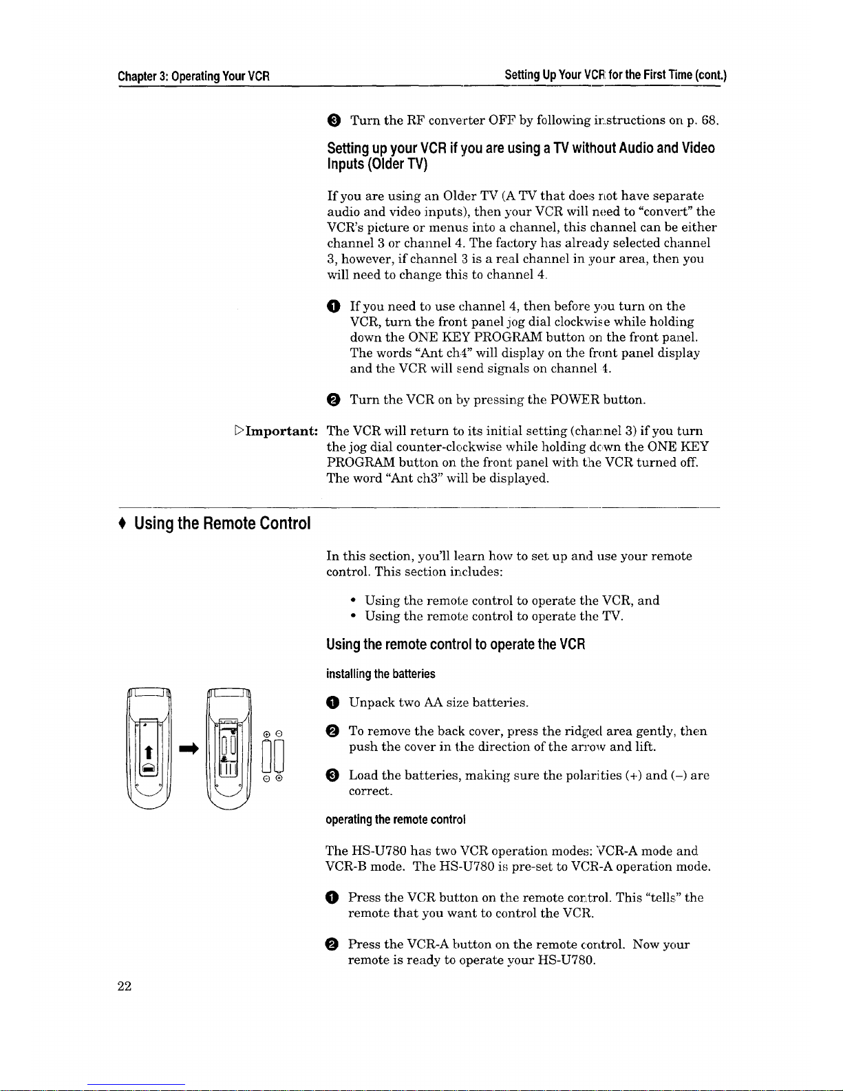
installingthe batteries
Unpack two AA size batteries.
To remove the back cover, press the rid_;ed area gently, then
push the cover in the direction of the an'ow and lift.
Load the batteries, making sure the polarities (+) and (-) are
correct.
operatingtheremotecontrol
The HS-U780 has two VCR operation mode,_: VCR-A mode and
VCR-B mode. The HS-U780 is pre-set to VCR-A operation mode.
Press the VCR button on the remote cor,Ltrol.This "tells" the
remote that you want to control the VCR.
Press the VCR-A button on the remote control. Now your
remote is ready to operate your HS-U780.
[:>Important:
[:>Important:
O Whilewithin 23feetoftheVCR,pointti_eremotecontrol
towardtheVCRandpressthebuttonsyoudesire.
usingoneremoteto operatetwoMitsubishiVCRs
If you have another Mitsubishi VCR (from 1986 or later) in
addition to this HS-U780, you can use the HS-U780 remote
control to operate both VCRs. There are two separate remote
control signal systems available with this remote. One is "VCR-A"
which can be used to operate all Mitsubishi VCRs introduced in
1986 and later. The _ther si_,qlal system is '_TCR-B" which will
operate the HS-U780 and selected other Mitsubishi VCRs.
To operate the two different VCRs separately (only one VCR
responding at a time) with the same remote, you need to program
one VCR to respond to VCR-A signals and the other VCR to
respond to VCR-B signals.
Since all Mitsubishi VCRs since 1986 and later will respc,nd to
VCR-A signals, then you should program the HS-U780 to respond
to VCR-B signals, and you also will need to program the remote
control to send VCR-B signals. Use the following procedures:
O
Make sure the HS-U780 is plugged in but turned off. On the
front pane] of the VCR, turn the shutt:[e ring to the left while
holding down the ONE KEY PROGRAM button on the front
panel. (The lette:_ "b" will appear on the :_ront panel display to
confirm this setting.)
On the remote, press the VCR button, then press the VCR-B
button. The remote will now send VCR-]_ signals.
O
To operate the other VCR... you need to reprogram the remote
to send VCR-A signals again. Press the VCR button on the
remote control, then press the VCR-A button. The remote will
now send VCR-A signals.
To reprogram the HS-U780 to respond to VCR-A signals again,
use the following procedures:
O
Make sure the HS-U780 is plugged in but turned off. On the
front panel of the, VCR, turn the shuttle ring to the right
while holding down the ONE KEY PROGRAM button on the
front panel. (The letter '%" will appear on the front panel
display to confirm this setting.)
Some other models of MitsuMshi VCRs can respond to VCR-B
signals. If your other VCR is one of these models, and you would
like to program that other VCR to respond to VCR-B signals, refer
to the owner's guide that came with the other VCR.
Some of the buttons may not function or they may operate differ-
ent features than expected, for the other VCF.
23

Chapter3:OperatingYourVCR Usingthe RemoteControl(cont.)
Brand of TV Brand code
buttons
Mitsubishi 1, 2, 3
Fisher 0
G.E. CANCEL
Goldstar 2, 9
Hitachi 8
Magnavox 4
NEC 2, 9
Panasonic 6
Pioneer AUDIO
Philips 4
Proscan CANCEL
Quasar 6
RCA CANCEL
Sanyo 0
Sharp 3, 5
Sony VCR/TV
Toshiba 7
Zenith ENTER
[:>Important:
DImportant:
[::>Important:
Usingthe remotecontrolto operatetheTV
The HS-U780 remote control can operate many of the frequently-
used functions of your TV. You only need one remote to operate
both your VCR and TV.
The HS-U780 remote control is pre-set to operate Mitsubishi
televisions, but it can also operate TVs from other manufacturers.
If you need to set your remote control for your particular b:rand of
television, follow the instructions on the next page.
settingupyour remotecontroltooperateyourTV
0 Turn off your TV.
O On the HS-U780 remote control, press the TV button on top of
the flip-up cover.
Flip up the (:over of the remote, then while holding in the PIP
button, press the (.'ode button listed to the left that corre-
sponds to the brand of your TV.
O Close the cover tightly, then press the POWER button. If your
TV turns on, your remote i,; set up to operate your brand of
TV.
If your TV does not turn on, repeat step _ using the next ('ode,
listed for the brand of your TV.
If none of the codes listed for the brand of your TV work, then
repeat step _ several times, using a different code button until
one works. The possible code buttons are: 0, 1.-9, CANCEL,
AUDIO, ENTER, and VCR/TV.
You do not need to perform this set-up again unless you change
the batteries, set up your remote for another brand of television,
or you get a new TV.
Once you have correctly set your remote control to operate your
TV, you will be able tc use the POWER, CHANNEL, VOLUME,
MUTE and number buttons to operate your TiT.
Depending on the model TV you have, all or some of the buttons
may not function, or they may operate different features than
indicated. You may need to use the TV's remoLe control.
Sometimes manufacturers will change the remote control codes
for their products, or they will use more than one code. If this is
the case, your remote may not be able to control your TV.
When you replace the batteries in your remote, the remote will
return to its initial setting (code button "1"). Repeat the steps
above to reset your remote control. If you enter a new code, the
previous code will be erased.
24
 Loading...