

Page 1
,,_ MITSUBISHI
Video
Cassette
Recorder
Owner's
Guide
o
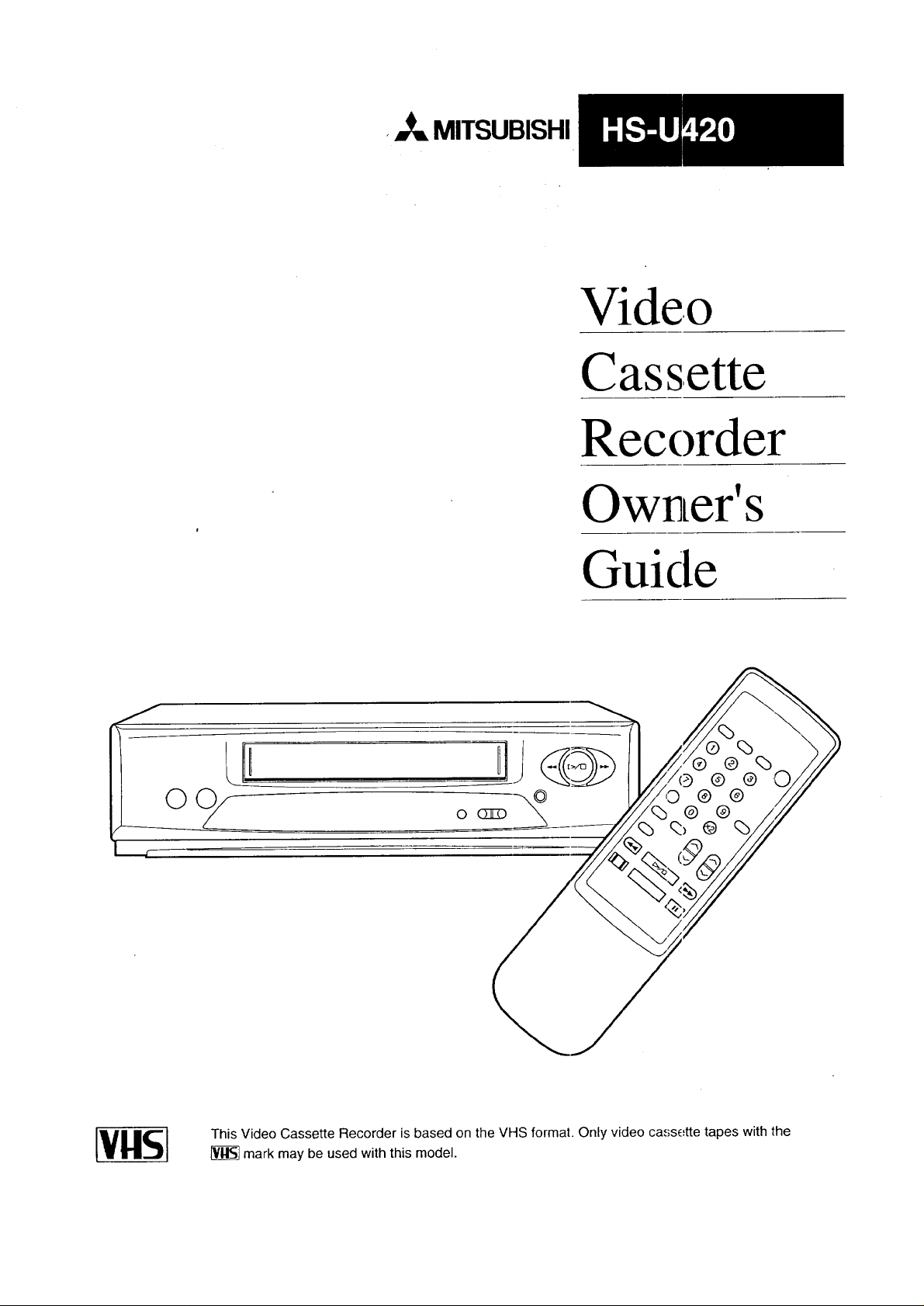
This Video Cassette Recorder is based on the VHS format. Only video cassette tapes with the
[_ mark may be used with this model.
Page 2
RISKOFELECTRICSHOCK
DONOTOPEN
!.._AU/ItL,PI_I" TO REDUCE THE RISK OF ELECTRIC SHOCK,
DO NOT REMOVE COVER (OR BACK).
NO USER-SERVICEABLE PARTS INSIDE.
REFER SERVICING TO QUALIFIED SERVICE PERSONNEL.
The lightning flash with arrowhead symbol, within
an equilateral triangle, is intended to alert tl:e user
to the presence of uninsulated "dangerous voltage"
within the product's enclosure that may be of
sufficient magnitude to constitute a risk of electric
shock to persons.
The exclamation point within an equilateral
triangle is intended to alert the user to the presence
of important operating and maintenance (serAcing)
instructions in the literature accompanying the
product.
IMPORTANT:
RECORDING OF COPYRIGHTED TELEVISION PROGRAMS MAY VIOLATE COP3fR [GHT LAW.
WARNING:
TO REDUCE THE RISK OF FIRE OR ELECTRIC SHOCK, DO NOT EXPOSE THIS PI::ODUCT TO RAIN
OR MOISTURE.
CAUTION:
TO PREVENT ELECTRIC SHOCK HAZARD, DO NOT USE THIS (POLARIZED) PLUG WITH AN
EXTENSION CORD, RECEPTACLE OR OTHER OUTLET UNLESS THE BLADES CAN BE FULLY
INSERTED TO PREVENT BLADE EXPOSURE.
NOTE TO CATV SYSTEM INSTALLER:
THIS REMINDER IS PROVIDED TO CALL THE CATV SYSTEM INSTALLER'S ATTENTION TO
SECTION 820-40 OF THE NEC WHICH PROVIDES GUIDELINES FOR PROPER GROUNDING AND, IN
PARTICULAR, SPECIFIES THAT THE CABLE GROUND StIALL BE CONNECTED TO THE
GROUNDING SYSTEM OF THE BUILDING, AS CLOSE TO THE POINT OF CABLE ENTRY AS
PRACTICAL.
Page 3
TableofContents
Important Safeguards ................................ 2
Preface
Welcome to Mitsubishi ............................... 5
Unpacking Your VCR .................................. 5
Chapter One
Getting to Know Your VCR ....................... 6
Front Panel Buttons and Functions ........... 6
Fluorescent Display ..................................... 7
Overview of the Remote Control ................. 8
Rear Panel Terminals .................................. 9
Chapter Two
Connecting Your VCR .............................. 10
Connecting the Antenna or Cable
to the VCR .............................................. 10
Connecting cable antennas .................... 10
Connecting other antennas .................... 12
Connecting separate UHF/VHF
antennas .............................................. 13
Connecting the Television ......................... 14
Determining if you need a splitter ......... 14
Connecting an older TV to the VCR ...... 15
Connecting a TV with audio and
video inputs ......................................... 15
Chapter Three
Operating Your VCR ................................. 17
Setting Up Your VCR for the First Time .. 17
Setting up your VCR if you are using a
TV without Audio and Video Inputs
(Older TV) ............................................ 17
Setting up your VCR if you are using a
TV equipped with Audio and Video
Inputs (Modern TV) ............................. 18
Using the Remote Control ......................... 18
Using the remote control to operate
"the VCR ............................................... 18
Using the remote control to operate
the TV .................................................. 19
Viewing the Picture Coming from
Your VCR ................................................ 20
Loading and Unloading Tapes .................. 21
Playing a Tape ........................................... 22
Playing back a tape ................................ 22
Using basic playback controls ................ 22
Selecting the On-screen Language ........... 23
Using the Menus to Set the Time ............. 23
Programming the VCR to Receive TV
Channels ................................................. 25
Programming channels automatically ..25
Using video mute .................................... 26
Adding and deleting channels ................ 27
Selecting a channel ................................. 28
Using the, Audio and Viideo Functions ...... 28
Descriptions of audio and video
functions ............................................... 29
Selecting and adjusting the audio and
video functions ....................................... 30
Recording ................................................... 31
Recording a current broadcast ............... 31
Programming your VCR to record ......... 32
Using One-Touch Recording (OTR) ....... 34
Using One Key Prograraming ................. 35
Using Quick Program ............................... 37
Notes about programmed recording .......38
Chapter Four
Using the Advanced Fea Lures ................. 41
Using the Advanced Play _ack Controls .... 41
Using special effects ............................... 41
Adjusting the tracking ........................... 42
Using the time counter ........................... 43
Displaying the Remaining Time and the
Present Time ........................................... 43
Displaying the time gauge and the
remaining time .................. . ................. .43
Display_ng the present ;ime ................... 44
Searching Techniques ..................... ........... 44
Quick searching ...................................... 45
Speed searching ...................................... 45
Using counter zero stop .......................... 45
Index so,arch technique,; ......................... 46
Using the Advanced Options ..................... 47
Using the auto daylight saving time ..... 47
Using the auto power saving (auto-ot_. 47
Setting the RF conver_er ........................ 48
Making a Copy of a Tape ........................... 49
Using your HS-U420 to record from
another VCR .......................................... 49
Using your HS-U420 to play back to
another VCR .......................................... 50
Using Child Lock ........................................ 50
Chapter Five
Troubleshooting .......................................... 51
Index .............................................................. 52
Page 4
IMPORTANTSAFEGUARDS
PLEASE READ ALL THESE INSTRUCTIONS REGARDING YOUR VCR AND RETAIN FOR
FUTURE REFERENCE. FOLLOW ALL WARNINGS AND INSTRUCTIONS MARKED ON THE
VCR.
Read Instructions
.
All the safety and operating instructions
should be read before the product is
operated.
2. Retain Instructions
The safety and operating instructions
should be retained for future reference.
.
Heed Warnings
All warnings on the product and in the
operating instructions should be adhered
to.
Follow Instructions
.
All operating and use instructions should
be followed.
.
Cleaning
Unplug this product from the wall outlet
before cleaning. Do not use liquid cleaners
or aerosol cleaners. Use a damp cloth for
cleaning.
.
Attachments
Do not use attachments not recommended
by the product manufacturer as they may
cause hazards.
.
Water and Moisture
Do not use this product near water -- for
example, near a bath tub, wash bowl,
kitchen sink, or laundry tub, in a wet
basement, or near a swimming pool, and
the like.
.
Accessories
Do not place this product on an unstable
°cart, stand, tripod, bracket, or table. The
product may fall, causing serious injury to
a child or adult, and serious damage to
the product. Use only with a cart, stand,
tripod, bracket, or table recommended by
the manufacturer, or sold with the prod-
uct. Any mounting of the product should
follow the manufacturer's instructions,
and should use a mounting accessory
recommended by the manufacturer.
.
A product and cart combination should be
moved with care. Quick stops, excessive
force, and uneven surfaces may cause the
product and cart combination to overturn.
10. Ventilation
Slots and openings in the cabinet are
provided for ventilati _n and to ensure
reliable operation of the product and to
protect it from overheating, and these
openi:ags must not be blocked or covered.
The openings should never be blocked by
placing the product o:_ a bed, sofa, rug, or
other similar surface. This product should
not be placed in a built-in installation
such as a bookcase or rack unless proper
ventilation is provided or the
manufacturer's insl;ructions have been
adhered to.
1].
Power Sources
This product should be operated only from
the type of power source indicated on the
marking label. If you are not sure of the
type of power supply Loyour home,
consult your product dealer or local power
company. For producl,s intended to
operaLe from battery power or other
sources, refer to the operating instruc-
tions.
12.
Grounding or Polarization
This product may be equipped with a
polarized alternating.-current line plug (a
plug having one blade wider than Lhe
other}. This plug will fit into the power
outlet only one way. ']?his is a safety
feature. If you are unable to insert, the
plug fully into the outlet, try reversing
the plug. If the plug should still fail to fit,
contact your electrician to replace your
obsolete outlet. Do not defeat the safety
purpose of the polari2 ed plug.
2
Page 5

13. Power-Cord Protection
Power-supply cords should be routed so
that they are not likely to be walked on or
pinched by items placed upon or against
them, paying particular attention to cords
at plugs, convenience receptacles, and the
point where they exit from the product.
14.
Outdoor Antenna Grounding
If an outside antenna or cable system is
connected to the product, be sure the
antenna or cable system is grounded so as
to provide some protection against
voltage surges and built-up static
charges.
Article 810 of the National Electrical
Code, ANSUNFPA 70, provides informa-
tion with regard to proper grounding of
the mast and supporting structure,
grounding of the lead-in wire to an
antenna discharge unit, size of grounding
conductors, location of antenna-discharge
unit, connection to grounding electrodes,
and requirements for the grounding
electrode.
EXAMPLE OF ANTENNA GROUNDING
' '_--_ANTENNA
- ----_k I LEAD IN WIRE
16.
Power Lines
An outside antenna system should not be
located in the vicinity of overhead power
lines or other electric light or power
circuit.,s, or where it can fall into such
power lines or circuits When installing
an out,Ade antenna sy_tem, extreme care
should be taken to keep from touching
such power lines or circuits as contact
with them might be fatal.
17.
Overloading
Do not overload wal]i outlets, extension
cords, and integral co_:venience recep-
tacles as this can re,;ul t in a risk of fire or
electric shock.
18.
Object and Liquid Entry
Never push objects of any kind into this
product through openi ags as they may
touch dangerous voltage points or short-
out parts that could result in a fire or
electric shock. Never spill liquid of any
kind on the product.
19.
Servicing
Do not attempt to service this product
yourself as opening or removing covers
may expose you to dangerous voltage or
other l:,azards. Refer all servicing to
qualified service personnel.
.,/_"_,_'11 _k_ /ANTENNA
,/ "F_ _ DISCHARGE UNIT
I EOU_PMENT--._I_ / /'-. J GROUNDING
__ CONDUCTORS
"-_'_'POWER SERVICE GROUNDING
NEC - NATIONAL ELECTRICAL CODE (NEC ART 250, PART H)
15.
Lightning
For added protection for this product
during a lightning storm, or when it is
left unattended and unused for long
periods of time, unplug it from the wall
outlet and disconnect the antenna or
cable system. This will prevent damage to
the product due to lightning and power-
line surges.
ELECTRODE SYSTEM
20.
Damage Requiring Service
Unplug this product from the wall outlet
and refer servicing to qualified service
personnel under the following conditions:
(a) When the power-sapply cord or plug
is damaged.
(b) If liquid has been spilled, or objects
have fallen into the product.
(c) If the product has been exposed to
rain or water.
(d) If the product does not operate
no:rmally by following the operating
instructions. Adiu:st only those
controls that are c_vered by the
operating instruct:ions as an improper
adjustment of other controls may
result in damage _nd will often
require extensive work by a qualified
technician to restore the product to
its normal operation.
(e) If the product has been dropped or
damaged in ony way.
(f) When the product exhibits a distinct
change in performance -- this indi-
cates a need for service.
3
Page 6

ImportantSafeguards
21.
Replacement Parts
When replacement parts are required, be
sure the service technician has used
replacement parts specified by the manu-
facturer or have the same characteristics
as the original part. Unauthorized substi-
tutions may result in fire, electric shock
or other hazards.
22.
Safety Check
Upon completion of any service or repairs
to this product, ask the service technician
to perform safety checks to determine
that the product is in proper operating
condition.
23.
Heat
The product should be situated away from
heat sources such as radiators, heat
registers, stoves, or other products (in-
cluding amplifiers) that produce heat.
CONDENSATION
Leave the VCR on, without a tape in it, for 2
hours if the VCR has been exposed to sudden
changes in temperature. Sudden temperature
changes cause moisture to form on the metal
parts inside the VCR. This moisture can cause
the tape to stick and damage the head.
Leaving the VCR on for a 2 hour period will
dry the inside of the VCR.
PROTECTTHEPOWERCORD
Do not damage the power cord. Damage to the
power cord may cause a fire or shock hazard.
When unplugging the power cord, please hold
it by the plug and remove it carefully.
DO NOTPLACEHEAVYOBJECTSON THE
RECORDER
Heavy objects placed on the recorder will
cause damage. (This does not mean your cable
box). The _op of the recorder is also slotted to
provide ventilation. Do no1;obstruct these
ventilation slots.
WHENNOTIN USE
When you finish operating the recorder,
always unload the cassette and turn OFF the
VCR POWER.
CAREOFTHE VIDEO CAS3ETTETAPES
• Avoid violent vibration or shock.
• Do not place in a location where strong
magnetic fields exist (near a motor, trans-
former or magnet).
• Never place or store in direct sunlight.
• Avoid dusty places.
• Place the cassette in tb _ cassette case and
store vertically.
• Never store tape in a high humidity loca-
tion.
INFORMATION
This equipment has been tested and found to comply with the limits for a Clas_ B digital device,
pursuant to Part 15 of the FCC Rules. These limits are designed to provide reasonable protection
against harmful interference in a residential installation. This equipment generates, uses, and
can radiate radio frequency energy and, if not installed and used in accordance with the instruc-
tions, may cause harmful interference to radio communications However, there is no guarantee
that interference will not occur in a particular installation. If this equipment does cause harmful
interference to radio or television reception, which can be determined by turning the equipment
off and on, the user is encouraged to try to correct the interference by one or more of the following
measures:
• Reorient or relocate the receiving antenna;
• Increase the separation between the equipment and receiver;
• Connect the equipment into an outlet on a circuit different from that to which the receiver
is connected;
• Consult the dealer or an experienced radio/TV technician for help.
Changes or modificatioIts not expressly approved by the party responsible for compliance could
void the user's authority to operate the equipment.
If necessary, the user should consult the dealer or an experienced radio/televisi _n technician for
additional suggestions. The user may find the following booklet prepared by the Federal Commu-
nications Commission helpful:
"How to Identify and Resolve Radio-TV Interference Problems."
This booklet is available from the US Government Printing Office, Washington D.C., 20402,
Stock No. 004-000-00345-4.
Page 7
PREFACE
Welcometo Mitsubishi
€ UnpackingYourVCR
Congratulations on your purchase of this Mitsubishi Video
Cassette Recorder. Your new VCR produces superior sound and a
high resolution VHS picture available. It includes VHS Hi-Fi
audio recording and playback, delivering compact disc-quality
audio.
Your owner's guide has been designed with easy-to-follow expla-
nations and directions. In addition, your VCR comes with
Mitsubishi's exclusive_on-screen operat:Lng system. This
system has been developed to simplify the operation of your VCR
with clear, understandable language and design.
Thank you for selecting our product and welcome to Mitsubishi.
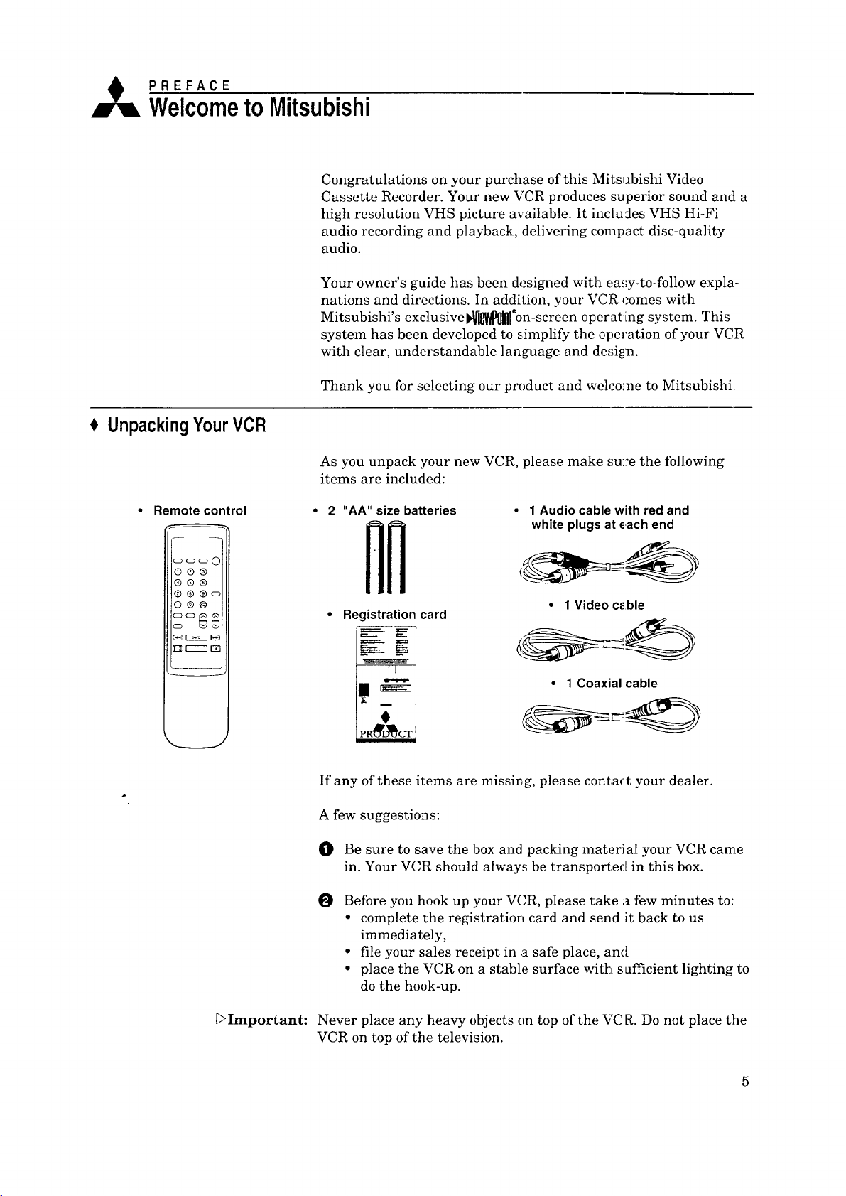
As you unpack your new VCR, please make su::e the following
items are included:
Remote control
ooo 0
©®®
®@®
®®®o
o®@
3°@8
2 "AA" size batteries • 1 Audio cablewith redand
__ white plugs at _,achend
• Registrationcard
If any of these items are missing, please conta(t your dealer.
A few suggestions:
O Be sure to save the box and packing material your VCR came
in. Your VCR should always be transported in this box.
O
Before you hook up your VCR, please take a few minutes to:
• complete the registration card and send it back to us
immediately,
• file your sales receipt in a safe place, and
• place the VCR on a stable surface with safficient lighting to
do the hook-up.
• 1 Video c_ble
• 1 Coaxial cable
[;>Important:
Never place any heavy objects on top of the VC R. Do not place the
VCR on top of the television.
5
Page 8

,_ CHAPTER ONE
GettingtoKnowYourVCR
Now that you have unpacked your player an J read through the
safety information, it's time to become familiar with the buttons
and controls.
If you are experienced with using VCRs, you may just want to
glance at this section and refer to it later. If VCRs are new to you,
you may want to take your time and become familiar with the
locations of all the controls.
On the following pages, you'll find information on:
$ FrontPanel Buttonsand Functions
t Overviewof the RemoteControl
FrontPanelButtonsandFunctions
FluorescentDisplay
RearPanelTerminals
J
5 6 7
cassette slot
Q
This is where you put the video cassette.
rewind and reverse search button
®
(REW)
Press to rewind a tape or to reverse
search. You can also use this button to
control the playback speed of a tape.
®
play and stop button (PLAY/STOP)
Press this button to play a tape and press
again to stop the tape. Also press to stop
tape related functions or to resume normal
playback from special effects.
234
' PLAy tOP I FF I
/
8 9 10 1
fast forward and fast forward search
button (FF)
Press this button to l_st forward a tape or
to fast forward search. You can also use
this to control the playback speed of a
tape.
_) power button (POWER)
Press this button to turn the VCR on or
off. You must turn ;;he VCR off after you
have programmed it to record.
_) eject button (EJECt)
Press this button to eject the cassette.
Page 9
(7) fluorescent display
See the next section.
remote control sensor
®
This receives signals from the remote
control. Do not block it.
®
one key program button
(ONE KEY PROGRAM)
Press to program the VCR to record.
® channel buttons (CIIANNEL)
Press these buttons to change channels.
Also use these buttons to adjust tracking
and picture vibration.
record button (REC/OTR)
©
Press this button once to record until the
end of the tape. Press repeatedly to set the
time for One-Touch Recording (OTR).
FluorescentDisplay
AM PM SUMO _ WE_H FR V_I_-I _RE_-_
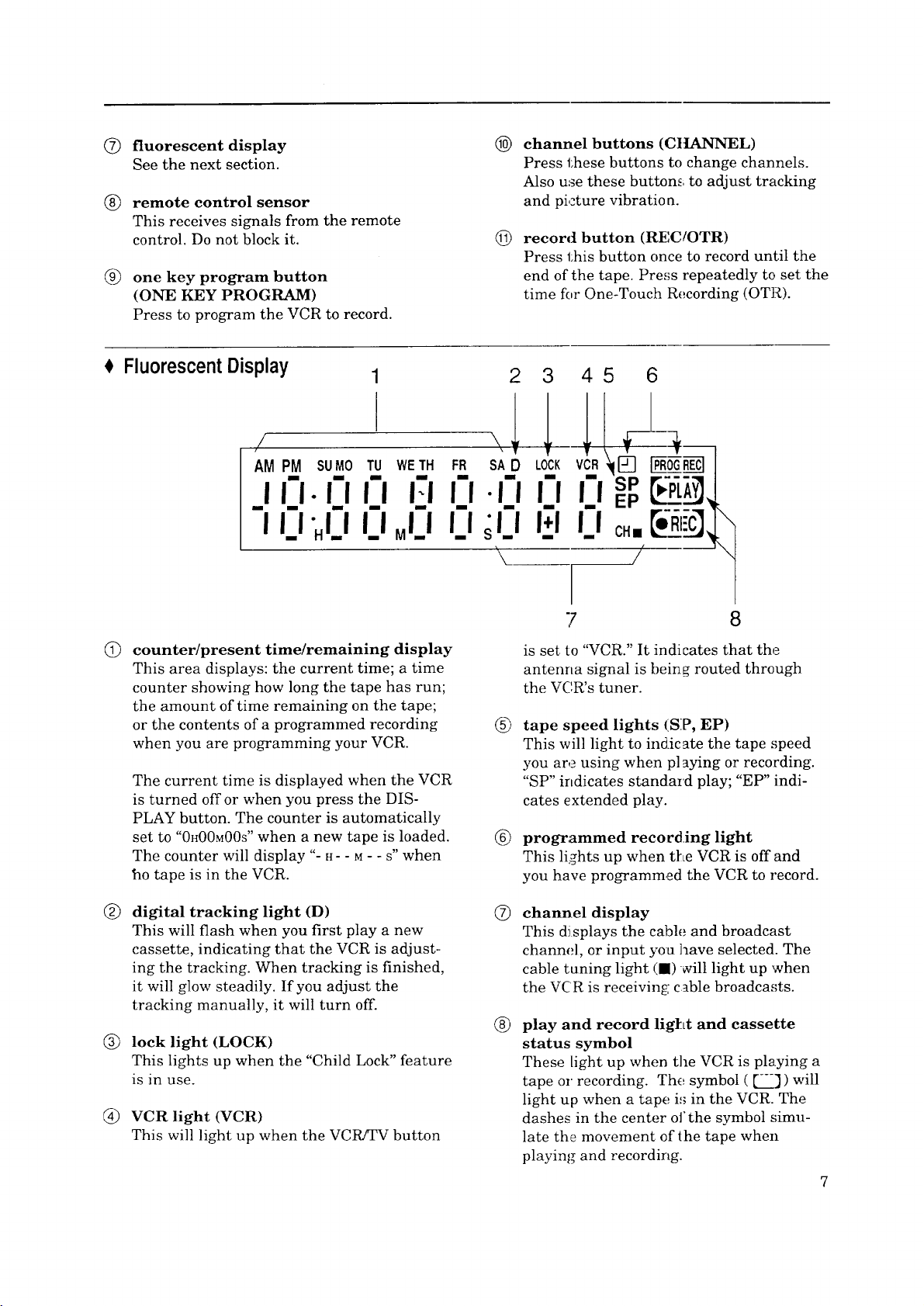
counter/present time/remaining display
This area displays: the current time; a time
counter showing how long the tape has run;
the amount of time remaining on the tape;
or the contents of a programmed recording
when you are programming your VCR.
The current time is displayed when the VCR
is turned off or when you press the DIS-
PLAY button. The counter is automatically
set to "0H00M00S" when a new tape is loaded.
The counter will display "- H- - M- - S" when
ho tape is in the VCR.
23 45 6
\
7 8
is set to "VCR." It indicates that the
antenna signal is being routed through
the VC,R's tuner.
®
tape speed lights (SP, EP)
This will light to indicate the tape speed
you are using when playing or recording.
"SP" indicates standard play; "EP" indi-
cates extended play.
®
programmed recording light
This lights up when tl_LeVCR is off and
you have programmed the VCR to record.
®
digital tracking light (D)
This will flash when you first play a new
cassette, indicating that the VCR is adjust-
ing the tracking. When tracking is finished,
it will glow steadily. If you adjust the
tracking manually, it will turn off.
®
lock light (LOCK)
This lights up when the "Child Lock" feature
is in use.
®
VCR light (VCR)
This will light up when the VCPVTV button
®
channel display
This di splays the cable and broadcast
channel, or input you have selected. The
cable tuning light Ill) _ill light up when
the VCR is receiving: cable broadcasts.
®
play and record lig[Lt and cassette
status symbol
These light up when the VCR is playing a
tape or recording. The symbol ([--']) will
light up when a tape is in the VCR. The
dashes in the center of the symbol simu-
late the movement of the tape when
playing and recording.
Page 10
Chapter1:GettingtoKnowYourVCR
€ Overviewofthe RemoteControl
--10
©@@
4
7q
8--
h
__
5
__
® @ @/o°,_
DISPLAY AUO_/I/IOEO VOLUME CHANNEL
(Z)
REW PLAYfSTOP_- FF
(_] I--__--] [E_
IADJUST ENTER ADJUSTI=
• "ilr-----i
OREC ME_,,x PAUSE
12 13
--16
--17
9
11
14
15
18
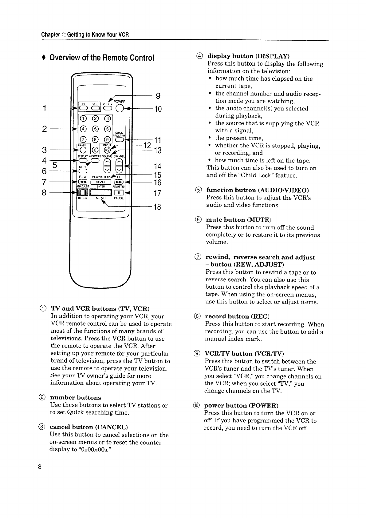
®
display button (DISPLAY)
Press this button to display the following
information on the television:
• how much time has elapsed on the
current tape,
• the channel numbe: and audio recep-
tion mode you are watching,
* the audio channel(s) you selected
during playback,
• the source that is supplying the VCR
with a signal,
• the present time,
• whc.ther the VCR is stopped, playing,
or recording, and
• how much time is l_.fton the tape.
This button can also be used to turn on
and off the "Child Lock" feature.
®
function button (AUDIO/VIDEO)
Press this button to adjust the VCR's
audio and video functions.
@
TV and VCR buttons (TV, VCR)
In addition to operating your VCR, your
VCR remote control can be used to operate
most of the functions of many brands of
televisions. Press the VCR button to use
the remote to operate the VCR. After
setting up your remote for your particular
brand of television, press the TV button to
use the remote to operate your television.
See your TV owner's guide for more
information about operating your TV.
number buttons
®
Use these buttons to select TV stations or
to set Quick searching time.
®
cancel button (CANCEL)
Use this button to cancel selections on the
on-screen menus or to reset the counter
display to "0H00MOOs."
®
mute button (MUTE)
Press this button to lsurn off the sound
completely or to restore it to its previous
volume.
®
rewind, reverse search and adjust
- button (REW, ADJUST)
Press t:his button to rewind a tape or to
reverse search. You can also use this
button to control the playback speed of a
tape. When using the on-screen menus,
use thi,_ button to selecL or adjust items.
®
record button (REC)
Press this button to start recording. When
recording, you can use ':he button to add a
manua] index mark.
®
VCR]TV button (VCB]TV)
Press this button to swi tch between the
VCR's tuner and the _r's tuner. When
you select "VCR," you c]aange channels on
the VCR; when you selcct "TV," you
change channels on the TV.
@
power button (POWl_:R)
Press this button to turn the VCR on or
off. If you have programmed the VCR to
record, you need to turz:Lthe VCR off.
Page 11
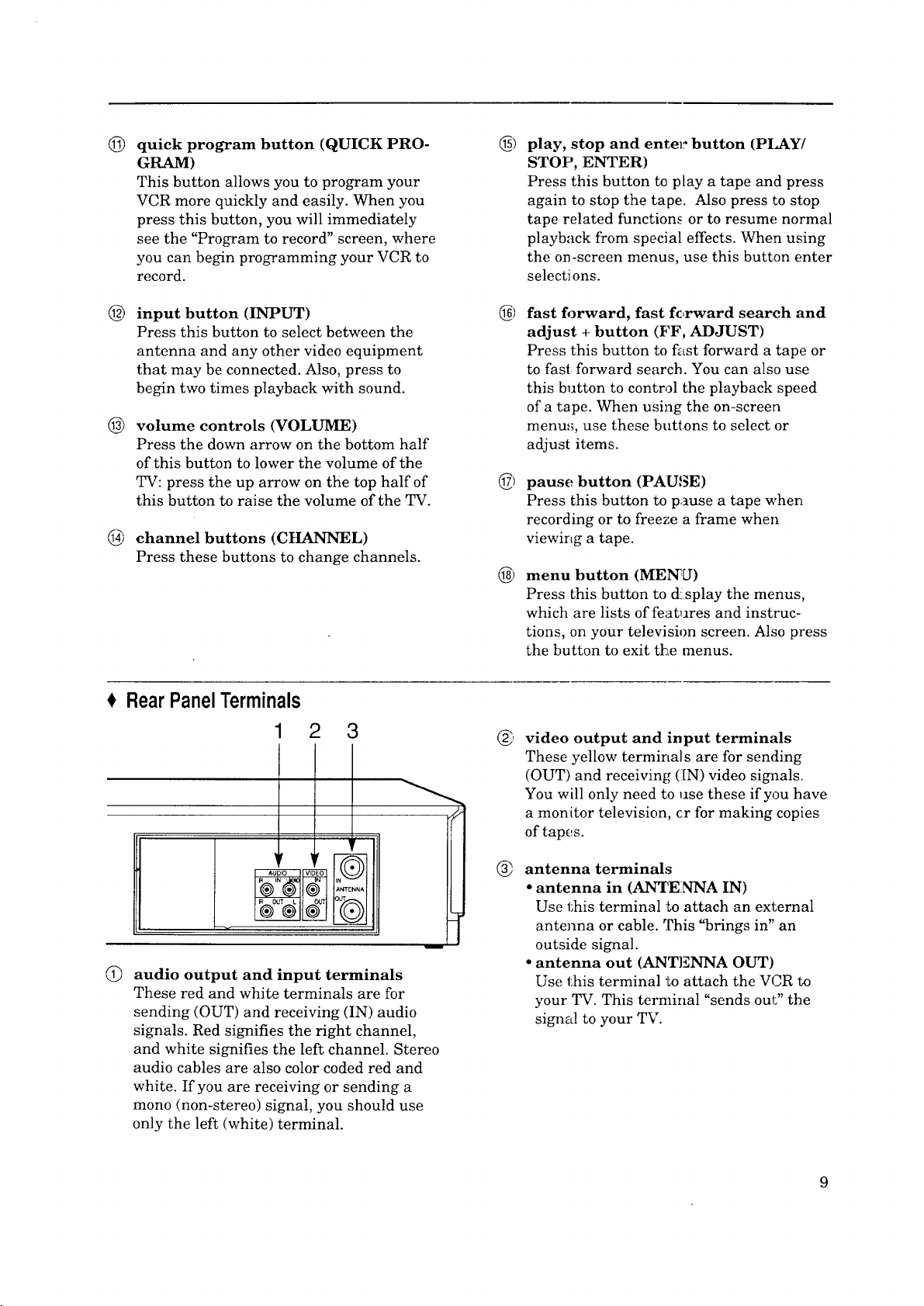
©
quick program button (QUICK PRO-
GRAM)
This button allows you to program your
VCR more quickly and easily. When you
press this button, you will immediately
see the "Program to record" screen, where
you can begin programming your VCR to
record.
@
play, stop and enter: button (PICKY/
STOP, ENTER)
Press this button to play a tape and press
again to stop the tape. Also press to stop
tape related functions or to resume normal
playback from special effects. When using
the on-screen menus, use this button enter
selecti ons.
@
input button (INPUT)
Press this button to select between the
antenna and any other video equipment
that may be connected. Also, press to
begin two times playback with sound.
@
volume controls (VOLUME)
Press the down arrow on the bottom half
of this button to lower the volume of the
TV: press the up arrow on the top half of
this button to raise the volume of the TV.
®
channel buttons (CHANNEL)
Press these buttons to change channels.
RearPanelTerminals
1 2 3
6) fast forward, fast fc,rward search and
adjust + button (FF, ADJUST)
Press this button to fast forward a tape or
to fast forward search. You can also use
this button to control the playback speed
of a tape. When using the on-screen
menus, use these buttons to select or
adjust items.
6) pause button (PAUSE)
Press this button to pause a tape when
recording or to freeze a frame when
viewing a tape.
® menu button (MEN'U)
Press this button to d!splay the menus,
which are lists of features and instruc-
tions, on your television screen. Also press
the button to exit the menus.
G
video output and input terminals
These yellow terminals are for sending
(OUT) and receiving (IN) video signals.
You will only need to use these if you have
a monitor television, cr for making copies
of tapes.
ANT[ INA
t
Q
audio output and input terminals
These red and white terminals are for
sending (OUT) and receiving (IN) audio
signals. Red signifies the right channel,
and white signifies the left channel. Stereo
audio cables are also color coded red and
white. If you are receiving or sending a
mono (non-stereo) signal, you should use
only the left (white) terminal.
antenna terminals
®
• antenna in (A1VI'ENNA IN)
Use this terminal to attach an external
antenna or cable. This "brings in" an
outside signal.
• antenna out (ANTENNA OUT)
Use this terminal to attach the VCR to
your TV. This terminal "sends out" the
signal to your TV.
Page 12
_k CHAPTER TWO
ConnectingYourVCR
Now that you're familiar with some of your VCR's features, you're
ready to connect the antenna and the television. You won't have
to complete all of the connections you see in this chapter --- make
only those connections that aF,ply to your equipment.
You should keep in mind that there are two steps you need to
take to connect your VCR: first, connect the antenna or cable to
the VCR, then connect the VCR to the television.
$ ConnectingtheAntennaor Cableto the VCR
0 ConnectingtheTelevision
ConnectingtheAntennaor Cableto the VCR
The first thing you need to do is connect the antenna or cable.
Because there are at least three different typcs of antennas, this
chapter will show how to connect all of them. You don't need to
make all the connections. First, find out what kind of antenna you
have. Then, make the connection for that typ_ of antenna. You
can then go to the next section, "Connecting the Television.."
This section shows you:
• Connecting cable antennas,
• Connecting other antennas, and
• Connecting separate UttF/VHF antennas.
Connectingcableantennas
If you have cable TV, this is the only antenna you need to [look
up. Because some cable companies require 8.c_ble box (for un-
scrambling cable signals), there are two kinds of cable connec-
tions shown: with and without a cable box_
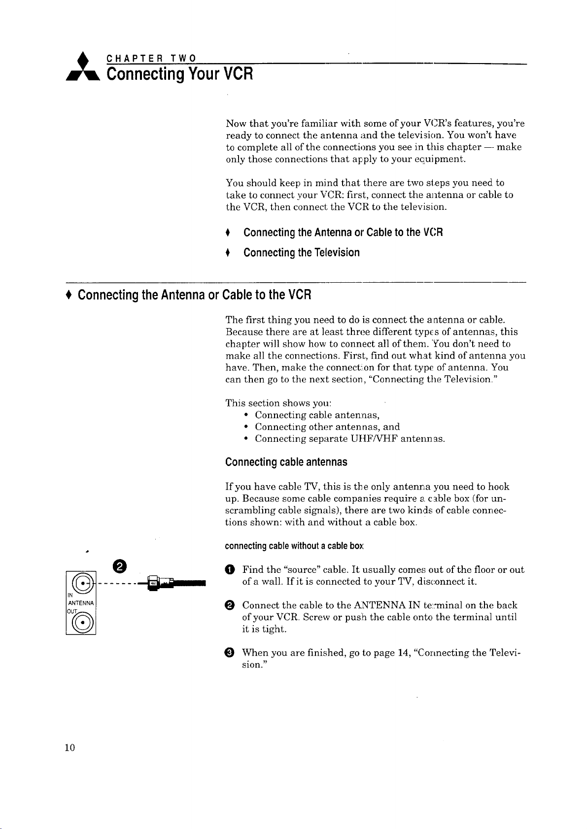
connectingcablewithouta cablebox
O Find the "source" cable. It usually comes out of the floor or out
of a wall. If it is connected to your TV, disconnect it.
Connect the cable to the ANTENNA IN te::minal on the back
of your VCR. Screw or puslh the cable onto the terminal until
it is tight.
O When you are finished, go to page 14, "Connecting the Televi-
sion."
10
Page 13
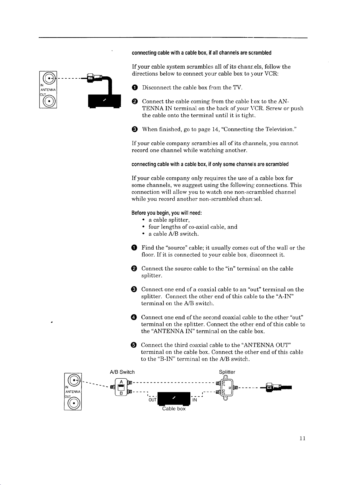
connectingcablewitha cablebox,ifallchannelsarescrambled
If your cable system scrambles all of its channels, follow the
directions below to connect your cable box to your VCR:
O Disconnect the cable box fcom the TV.
O Connect the cable coming from the cable kox to the AN-
TENNA IN terminal on the back of your VCR. Screw or push
the cable onto the terminal until it is tighl;.
When finished, go to page 14, "Connecting the Television."
If your cable company scrambles all of its channels, you cannot
record one channel while watching another.
connectingcablewithacablebox,ifonlysomechannelsarescrambled
If your cable company only requires the use of a cable box fbr
some channels, we suggest using the following connections. This
connection will allow you to watch one non-scrambled channel
while you record another non-scrambled channel.
Beforeyoubegin,youwillneed:
• a cable splitter,
• four lengths of co-axial cable, and
• a cable MB switch.
A/B Switch
Find the "source" cable; it usually comes', out of the wall or the
floor. If it is connected to your cable box: disconnect it.
Connect the source cable to the "in" terminal on the cable
splitter.
Connect one end of a coaxial cable to an "out" terminal on the
splitter. Connect the other end of this came to the "A-IN"
terminal on the A/B switch.
0 Connect one end of the second coaxial cable to the other "out"
terminal on the splitter. Connect the other end of this cable to
the "ANTENNA IN" terminal on the cable box.
Connect the third coaxial cable to the "ANTENNA OUT"
terminal on the cable box. Connect the other end of this; cable
to the "B-IN" terminal on the A/B switch.
Splitter
___,..... _ .......
'OUT
Cable box
IN
11
Page 14
Chapter2:ConnectingYourVCR ConnectingtheAntennaor Cableto theVCR(cont.)
O Connect the fourth coaxial cable to'the "OUT" terminal on the
A/B switch. Connect the other end of this cable to the ':'AN-
TENNA IN" terminal on your VCR.
O When you are finished, go to page 14, "Connecting the Televi-
sion."
With this connection, you should set the A!B switch to "B" only
when you are recording a scrambled channel In that case, you
should set your VCR to record channel 3 (or _:), and manually set
the cable box to the channel you wish to record.
You should leave the A/B switch set to "A" for all other situations.
If you have questions concerrJng your cable system, please
contact your cable company.
_Important:
With this connection, you ca_ not record a scrambled channel and
watch a non-scrambled channel at the same time. You also cannot
watch a scrambled channel a:ad record a non-scrambled channel
at the same time.
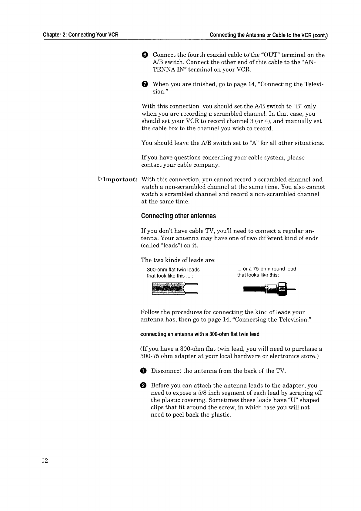
Connectingotherantennas
If you don't have cable TV, you'll need to connect a regular an-
tenna. Your antenna may have one of two different kind of ends
(called "leads") on it.
The two kinds of leads are:
300-ohm flat twin leads
that look like this ... :
Follow the procedures for connecting the kind of leads your
antenna has, then go to page 14, "Connecting the Television."
connectinganantennawitha 300-ohmflat twinlead
(If you have a 300-ohm flat twin lead, you will need to purchase a
300-75 ohm adapter at your local hardware or electronics _,;tore.)
... or a 75-oh'n round lead
that looks like this:
12
0 Disconnect the antenna from the back of the TV.
O Before you can attach the antenna leads to the adapter, you
need to expose a 5/8 inch segment of each lead by scraping off
the plastic covering. Sometimes these leads have "U" shaped
clips that fit around the screw, in which case you will not
need to peel back the plastic.
Page 15
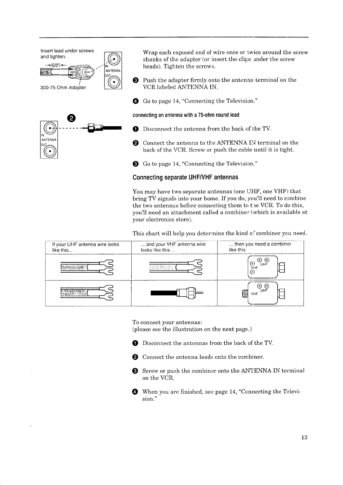
Insert lead under screws
Wrap each exposed end of wire once or twice around the screw
shanks of the adapter (or insert the clips under the screw
heads). Tighten the screws.
and tighten.
300-75 Ohm Adapter
O
If your UHF antenna wire looks
like this...
O Push the adapter firmly onto the anten:na terminal on the
VCR labeled ANTENNA IN.
O Go to page 14, "Connecting the Television."
connectinganantennawitha75-ohmroundlead
O Disconnect the antenna from the back: of the TV.
O Connect the anterma to the ANTENNA IN terminal on the
back of the VCR. Screw or push the cable until it is tight.
O Go to page 14, "Connecting the Television."
Connecting separateUHF/VHFantennas
You may have two separate antennas (one UHF, one VHF) that
bring TV signals into your home. If you do, you'll need to combine
the two antennas before connecting them to the VCR. To do this,
you'll need an attachment called a combiner (which is available at
your electronics store).
This chart will help you determine the kind of combiner you need.
... and your VHF antenqa wire ... then you need a combiner
looks like this ... like this.
)
To connect your antennas:
(please see the illustration on the next page.)
O Disconnect the antennas from the back of the TV.
Connect the antenna leads onto the combiner.
Screw or push the combiner onto the ANTENNA IN terminal
on the VCR.
When you are finished, see page 14, "Connecting the Televi-
sion."
13
Page 16
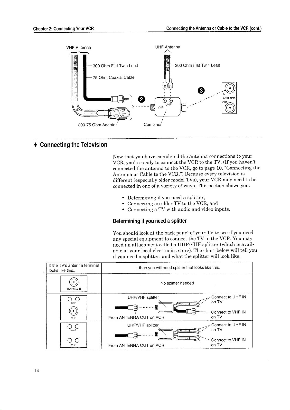
Chapter2: ConnectingYourVCR ConnectingtheAntennacr CabletotheVCR(cont.)
VHF Antenna
)hm Flat Twin Lead
Ohm Coaxial Cable
300°75 Ohm Adapter
Connecting the Television
UHF Antenna
--300 Ohm Flat Twit Lead
Combiner
Now that you have completed the antenna connections to your
VCR, you're ready to connect the VCR to the FV. (If you haven't
connected the antenna to the VCR, go to page 10, "Connecting the
Antenna or Cable to the VCR.") Because every television is
different (especially older model TVs), your VCR may need to be
connected in one of a variety of ways. This section shows you:
If the TV's antenna terminal
looks like this...
OO
UHF
®
VHF
O©
UHF
• Determining if you need a splitter,
• Connecting an older TV to the VCR, and
• Connecting a TV with audio and video inputs.
Determining if you need asplitter
You should look at the back panel of your TV to see if you need
any special equipment to connect the TV to the VCR. You may
need an attachment called a UHF/VHF splitter (which is avail-
able at your local electronics ,_tore). The char_; below will tell you
if you need a splitter, and wh._t the splitter will look like.
... then you will need splitter that looks like t-fis.
No splitter needed
UHF/VHF splitter y. Connect to UHF IN
_ oq TV
L__J_ _--- Connect to VHF IN
From ANTENNA OUT on VCR on TV
UHF/VHF splitter _j, Connect to UHF IN
--I_F__" Oq TV
14
O©
VHF
From ANTENNA OUT on VCR on TV
Page 17
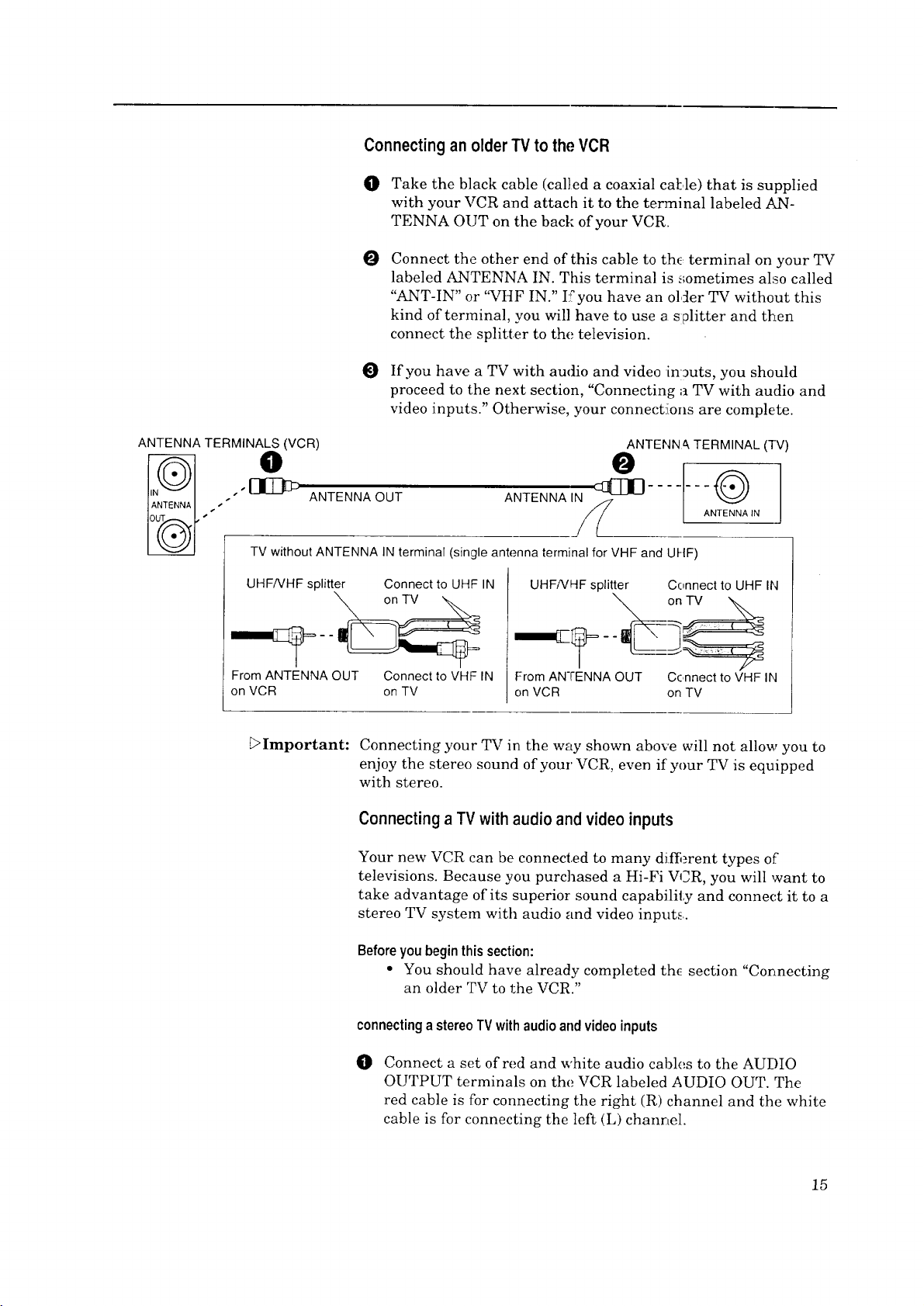
Connecting an olderTV to the VCR
O Take the black cable (called a coaxial cal:,le) that is supplied
with your VCR and attach it to the terminal labeled AN-
TENNA OUT on the back of your VCR.
O
Connect the other end of this cable to the terminal on your TV
labeled ANTENNA IN. This terminal is sometimes also called
"ANT-IN" or "VHF IN." I:fyou have an older TV without this
kind of terminal, you will have to use a splitter and then
connect the splitter to the television.
I_ If you have a TV with audio and video in:_uts, you should
proceed to the next section, "Connecting a TV with audio and
video inputs." Otherwise, your connect!ions are complete.
ANTENNA TERMINALS (VCR)
.''@ ANTENNA OUT
s
TV without ANTENNA IN terminal (single antenna terminal for VHF and UHF)
UHFNHF splitter Connect to UHF IN
From ANTENNA OUT Connect to VHF IN
on VCR on TV
_Important:
ANTENN & TERMINAL (TV)
O
ANTENNA IN
UHFNHF splitter Connect to UHF I1',1
From ANTENNA OUT Connect to VHF IN
on VCR on TV
Connecting your TV in the way shown above will not allow you to
enjoy the stereo sound of your VCR, even if your TV is equipped
with stereo.
Connecting a TVwith audio and video inputs
Your new VCR can be connected to many difS_rent types of
televisions. Because you purchased a Hi-Fi VCR, you will want to
take advantage of its superior sound capability and connect it to a
stereo TV system with audio and video inputs.
Beforeyou beginthis section:
° You should have already completed the section "Connecting
an older TV to the VCR."
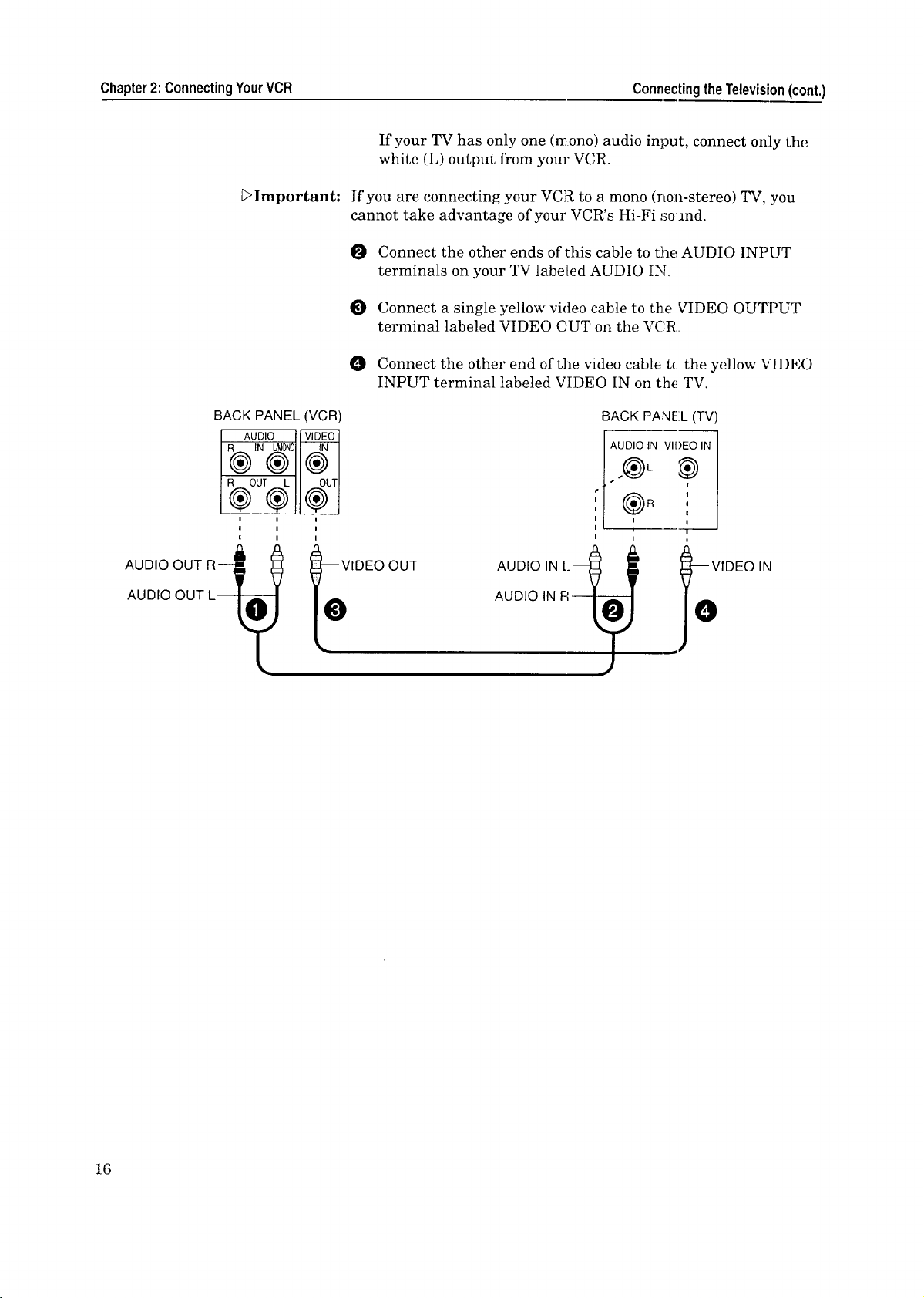
connectinga stereoTVwithaudioandvideoinputs
0 Connect a set of red and white audio cables to the AUDIO
OUTPUT terminals on the VCR labeled AUDIO OUT. The
red cable is for connecting the right (R) channel and the white
cable is for connecting the left (L) channel.
15
Page 18
Chapter2: ConnectingYourVCR ConnectingtheTelevision(cont.)
If your TV has only one (rnono) audio input, connect only the
white (L) output from your VCR.
[:>Important: If you are connecting your VCR to a mono (non-stereo) TV, you
cannot take advantage of your VCR's Hi-Fi sound.
O Connect the other ends ofthis cable to the AUDIO INPUT
terminals on your TV labelled AUDIO IN.
Connect a single yellow video cable to the VIDEO OUTPUT
terminal labeled VIDEO OUT on the VCR
O Connect the other end of the video cable tc: the yellow VIDEO
INPUT terminal labeled VIDEO IN on the TV.
AUDIO OUT R4
AUDIO OUT L
BACK PANEL (VCR)
AUDIO VIDEO
R OUT L OUT
®®®
--VIDEO OUT
O
BACK PANEL (TV)
AUDIO IN [._
AUDIO IN FI
E O
16
Page 19

A CHAPTER THREE
OperatingYourVCR
Now that you've completed your antenna, VCR, and TV connec-
tions, you're ready to start enjoying your equipment. To get the
most satisfaction out of your VCR, you shoul5 carefully read the
two sections, "Setting Up Your VCR for _he First Time" and
"Viewing the Picture Coming from Your VCF." Then you can start
exploring what your new VCR can do.
In this chapter, you'll learn:
+ SettingUpYourVCRfor the FirstTime
$ Usingthe RemoteControl
+ Viewingthe PictureComingfrom YourVCR
$ Loadingand UnloadingTapes
+ Playinga Tape
$ Selecting the On-screen Language
+ Using the Menusto Set the Time
$ Programming the VCRto ReceiveTV Channels
Using the Audio and Video Functions
$ Recording
I Setting Up YourVCRfor theFirst Time
It's important that your VCR is set up correcti[y before you try to
use it. If you carefully read this section, you will avoid confusion
later and get the most out of operating your system.
This section teaches you about.:
• Setting up your VCR if you are using a I'V without Audio
and Video Inputs (Older TV), and
• Setting up your VCR if you are using a 'IV equipped with
Audio and Video Inputs (Modern TV).
Beforeyou begin,youshould:
• have completed your anl;enna, VCR, and TV connections.
Settingup yourVCR ifyou are using a TV withcutAudioand Video
Inputs(OlderTV)
O Turn on your TV and tune it to channel 3 (,r 4, whichew_r is
NOT used for broadcast in your area.
17
Page 20

Chapter3:OperatingYourVCR SettingUpYourVCRFortheFirstTime(cont.)
0
If you tuned the TV to channel 4 in step O, press the CHAN-
NEL • button and the ONE KEY PROGRAM button on the
front panel at the same time with the VCR turned off. The
word "Ant ch4" will display on the front panel display of the
VCR and the VCR will send signals on chaanel 4. (If you
tuned the TV to channel 3, you don't need 1_odo this.)
Turn the VCR on by pressing the POWER button.
Important:
€ UsingtheRemoteControl
The VCR will return to its initial setting (chanael 3) if you press
the CHANNEL • button and the ONE KEY PROGRAM button
on the front panel at the same Lime with the V_R turned off.
Setting up yourVCR if you are using aTV equippedwithAudioand
VideoInputs(ModernTV)
Turn on your TV and switch it to the correct external input.
(For most Mitsubishi TVs, this means pres_ing the TV's
INPUT button until you see the words "F,xt-l" on the screen.)
Turn the VCR on by pressing the POWER button.
In this section, you'll learn how to set up and u _e your remote
control.
This section includes:
• Using the remote control to operate the VCR, and
• Using the remote control to operate the UV.
Usingthe remotecontroltooperatethe VCR
18
installingthe batteries
O Unpack two AA size batteries.
To remove the back cover, press the ridged area gently, then
push the cover in the direction of the arrew and lift.
Load the batteries, making sure the polarit!es (+) and (-) are
correct.
operatingtheremotecontrol
O Press the VCR button on the remote control. This "tells" the
remote that you want to control the VCR.
While within 23 feet of the VCR, point the remote control
toward the VCR and press ti_e buttons you desire.
Page 21

Brand of TV
Mitsubishi
Fisher
G.E.
Goldstar
Hitachi
JVC
Magnavox
NEC
Panasonic
Pioneer
Philips
Proscan
Quasar
RCA
Sanyo
Sharp
Sony
Toshiba
Zenith
Brand code
buttons
1,2,3
0
CANCEL
2,9
8
VOLUME V
4
2,9
6, MUTE
CHANNEL V
4
CANCEL
6
CANCEL
0
3,5
DISPLAY
7
INPUT
Usingthe remotecontrolto operatethe TV
The HS-U420 remote control can operate many of the frequently-
used functions of your TV. This way, you nc.ed to use only one
remote to operate both your VCR and TV.
The HS-U420 remote control :_spre-set to ope_'ate Mitsubishi
televisions, but it can also opc,rate TVs from ether manufacturers.
If you need to set your remote control for your particular brand of
television, follow the instructions below.
settingupyourremotecontrolto operateyourTV
0
Turn off your TV.
0
On the HS-U420 remote control, press the TV button.
While holding in the POWER button, press the code button
O
listed to the left that corresponds to the brand of your 'IV.
O
Once your TV has turned on, your remote is set up to operate
your brand of TV.
You do not need to perform this set-up again ,anless you change
the batteries, set up your remote for another brand of television,
or you get a new TV.
Once you have correctly set your remote control to operate your
TV, you will be able to use the POWER, CHANNEL, VOLUME,
MUTE and number buttons to operate your TV.
_>Important:
_>Important:
_>Important:
Depending on the model TV you have, all or some of the buttons
may not function, or they may operate different features than
indicated above. You :may need to use the TV's remote control.
Sometimes manufacturers will change the remote control codes
for their products, or they wilt use more th_,n one code. If this is
the case, your remote may no_;be able to cont:ol your TV.
When you replace the batteries in your remote, the remote will
return to its initial setting (code button "1"). Repeat the steps
above to reset your remote control. If you enter a new code, the
previous code will be erased.
operatingyourTVwiththe HS-U420remotecontrol
O Press the TV button on the HS-U420 rem _te control.
Point the remote control towards the remote sensor on the TV
and press the desired butl_ons.
O To once again control the VCR, press the VCR button.
19
Page 22

Chapter3: OperatingYourVCR Usingtl'eRemoteControl(cont.)
_Important:
Because of variations among models, some or all buttons may not
work, or they may operate different functions than listed, for your
particular TV. If this occurs, you may need to use your TV remote
control.
ViewingthePictureComingfrom YourVCR
This is the most important part of using your VCR, but often the
most confusing: how do you view a picture coming from the VCR?
Beforeyou begin,you should know:
• whether you are viewing a "Modern TV" or an "Older TV."
(See page 17.)
Viewingthe picturecomingfrom yourVCR i! you are usingan
older TV
O Turn on your TV and tune it to channel 3 or 4.
O Turn on the VCR by pressing the POWER button.
Io o -=¢D.A
i®@®_il
Check to see if the '_VCR" light on the front panel display is
lit. If it is not lit, press the VCR/TV buttor until it is lit.
ffl_EI
_Important:
You are viewing the picture from your VCRI
With this set-up, you will use the VCR/TV butLon when recording,
when viewing tapes or broadcast stations through your VCR, or
before using the VCR's menus. You also use tl: e VCR!TV button
to switch back to normal TV viewing.
If you set the "RF converter" setting of the ,u s_om_ze choices
menu to ON, you don't need to use the VCR/TV button when
viewing tapes. (See page 48. )
Viewingthe picturecoming from yourVCR ifyou are usinga
modernTV
0
Turn on your TV and switch it to the corre :t external input.
(For most Mitsubishi TVs, this means pressing the TV's;
INPUT button until you see the words "ExL-I" or "Input-l" on
the screen.)
Turn the VCR on by pressing the POWER button.
You are viewing the picture from your VCR!
If you wish to return to normal TV viewing, ,_witch your TV's
input back to its previous position.
20
L>Important: If you are using a modern TV, be sure to set Lhe "RF converter" of
the "Customize choices" menu i:o OFF to prevent noise in the
picture. (See page 48. )
Page 23

bImportant: If yoursystemincludesahometheaterreceiveroranA/V
receiver,refertoyourhometheaterreceiver'sowner'sguide.
LoadingandUnloadingTapes
Loadingatape
INCORRECT_
[>Important:
[>Important:
Tapes can be loaded into your VCR as long as the VCR is plugged
in. Even when the VCR POWER is off, loading a tape will auto-
matically turn the VCR on. Use only tapes that have a [_ label.
O Hold the tape so that the long narrow edge with the contents
label faces towards you. The other edge is hinged and should
face towards the VCR. The plastic windo_ that shows the
videotape should face up.
O Gently insert the tape into the cassette slot until the VCR
automatically takes it in.
Your VCR will eject the tape if you improperly load it. If the VCR
ejects the tape, remove the tape, check to see that the contents
label is facing you, that the geared tape reels are facing down-
wards, wait a few seconds, and try again.
Unloading a tape
q[]} Press the EJECT button on the front of the VCR. If the VCR
POWER is off, the VCR will turn on, eject the tape, then turn
off.
Remove the tape.
[>Important: You cannot eject a tape while !Ltis recording. You must first stop
Erasureprevention tab
_Warning: I
the recording.
Preventing accidentalerasure
Tapes come with a tab that, when removed, prevents you from
recording on the tape. If you a_tempt to recard over a tape that.
has had this tab removed, the VCR will eject it. To record over
such a tape, simply place a piece of vinyl tape over the opening.
Usingrepairedtapes
We recommend that you take any broken or torn tapes to a
professional for repair. If you repair a torn tape with improper
materials, you could damage your VCR when you play the tape.
21
Page 24

Chapter3: OperatingYourVCR
€ PlayingaTape
Now that your VCR is connected and properly set up, and you
know how to view a picture coming from your VCR, it's time to
play a tape.
This section describes:
• Playing back a tape, and
• Using basic playback controls.
Playing back a tape
Beforeyou begin, youneedto know:
• how to view the picture coming from your VCR (page 20).
O To play a tape, load a pre-recorded cassette.
O Press the PLAY/STOP button on the front panel or on the
remote control.
The VCR will automatically play the tape at the correct speed.
When the VCR reaches the end of the tape, Jt will automatically
rewind the tape and stop. You can stop playing by pressing PLAY/
STOP.
_>Important:
Using basic playback controls
rewindinga tape
Press the REW button on the remote control o:" on the front panel.
If the tape is stopped, you will begin rewinding. If the tape is
playing, you will begin "reverse speed search.':
fastforwardinga tape
Press the FF button on the remote control or on the front pane].
If the tape is stopped, you will begin fast forwarding. If the tape is
playing, you will begin "forward speed searchY
pausingatape
Press the PAUSE button on the remote control to freeze the
picture on the screen.
If you leave the VCR in pause tbr 5 minutes, tt:.e VCR will auto-
matically stop to prevent damage to the tape.
controllingvibrationduring stillframe
22
If the picture vibrates (luring sl;i]l frame, press the CHANNEL
buttons on the front panel untill the picture is steady.
Page 25

i SelectingtheOn-screenLanguage
You can set your VCR to display on-screen messages, menus, and
functions in English, Spanish or French. You should do this
before you use the menus or ,;et any audio/video functions.
Beforeyou begin,you needto know:
• how to view the picture coming from you: VCR. (See page 20.)
0
Seled'r, Languase
_L_
0 Espafiol
0 Fran?ais
_Important: The "Select Language" menu is unique. While all other menus can
Make sure you are viewing the picture coming from your
VCR. Then. press the MF,NU button on the remote control. If
this is the first time the menus have been used, you will see
the menu for selecting an on-screen lang_age.
Press the ADJUST buttons on the remote control to highlight
0
the desired language. The ADJUST + bu:ton moves upward;
the ADJUST - button moves downward.
O Press the ENTER button on the remote control. The menu
will change to the '_VCR IvIain Menu."
O Press the MENU button _o exit the menus.
be accessed at almost any time, the "Select Language" menu will
not automatically appear again after it is fir_;t set. To see the
"Select Language" menu, turn off the VCR and unplug the power
cord. Leave it unplugged for about two minul;es, then follow the
procedure on this page.
i UsingtheMenusto Setthe Time
This section will show you how to use the on-screen menus. You
will use the menus to operate many features, such as setting the
time, programming to record and memorizir g channels. On the
on-screen menus, the selected item is indicated in white.
Your choices are:
_Prosram to record
_£usZomize choices
Beforeyoubegin,youneedto know:
O Make sure you are viewing the picture coming from your
Your choices are:
_Memorize channels
Add/deleZe channels
• how to view the picture coming from your VCR (page 20),
VCR. Then, press the ME',NU button on the remote control.
You will see the "VCR Main Menu." Make sure the words
"First Time Set-Up" is highlighted. If'it i=_not, use the AD-
JUST buttons to highlight it.
Press the ENTER button. The "First Time Set-Up" menu will
appear. The word "Set the clock" will be highlighted. Press
the ENTER button.
23
Page 26

Chapter3:OperatingYourVCR Usin_lthe MenustoSetthe Time(cont.)
O
You will see the "Set the clock" menu. The words "Daylight
[e]l_&'_J_,,'lm-_L'bl,_ H (ON )
0 Month --
0 Year --
0 Date --
0 Time
savings" will be h:[ghlighti_d. Press the ADJUST buttons to
select the daylight savings setting ON or OFF. If you are
currently following daylight savings, select ON. Otherwise,
select OFF. Press the ENTER button.
O Press the ADJUST buttors until the correct month appears
on screen. Press the ENTER button.
<_)Daylisht savir%ss (ON)
_) Year 19'96
ODate 1 Saturday
_) Time 12 :OOpm
Press the ADJUST buttons to set the yea]'. Press the ENTER
button.
ODaylisht savinss (ON)
0 Month Ju_ne
ODa_e 1Sa'turday
0 Time 12:00Pm
-1996-
ODaylisht savinss (ON)
0 Month June
0 Year _ 1996_
OTime _ l_:OOpm
ODaylisht savinss (ON)
0 Month June
<_Year 1996
ODate 16 S_nday,
ODaylisht savines (ON )
0 _onth June
0 Year 1996
ODa_e 16 Sunday
--16 Sunday--
7_3Opm
Press the ADJUST buttons to set the date. Press the ENTER
button.
0
The hour numbers and the am/pm indicator will be blinking.
Press the ADJUST buttons to set the hour and am!pm at the
same time. The ADJUST -_ button moves l_heclock forward;
the ADJUST - moves the clock backward_,_.
Press the ENTER button.
O
The minutes will now be blinking. Press the ADJUST buttons
to set the minutes. When you have set tlhe correct time, press
the ENTER button. The display will return to the "First Time
Set-Up" menu and the clo(k will start run ning.
24
Press the MENU button once to return to the "VCR Main
O
Menu"; press the MENU button again to turn off the menus.
Page 27

Ifyouwantto adjustthe clockmanuallyforDaylightSavingTime,
After you have displayed the "Set the clock" menu, make sure
that the words "Daylight savings" is highligktcd. Then press the
ADJUST buttons to select ON or OFF. If you _.elect ON, the VCR
will set the clock forward one hour. If you select OFF, the VCR
will set the clock back one hour.
L>Important: If you want the VCR to adjust the clock automatically for Day-
light Saving Time, set the "Auto D.S.T." of the "Customize
choices" menu to ON. (For more information on this feature,
please see page 47.)
Ifyousetthe"Auto D.S.T."ofthe"Customizechoices"'menuto ON,
Your VCR will change automatically the clock from 2 AM to 3 AM
on first Sunday in April and turn the "Daylight savings" setting
to ON; your VCR will change the clock from 3 AM back to 2 AM
on last Sunday in October and turn the settin _ to OFF. This
means if you are currently following Daylight Saving Time, "ON"
will be displayed; otherwise, "OFF" will be displayed. (You
cannot change the "Daylight savings" setting manually.)
_>Important: Any time you adjust this setting, check youc programmed record-
ings to be sure they are set to the correct time.
ProgrammingtheVCRto ReceiveTVChannels
Before your VCR can receive _elevision channels, you need to
program all of the channels you can receive into your VCR.
Fortunately, our menu systera makes this an easy process. This
section will also explain some other channel-related functions.
This section explains:
• Programming channel:_ automatically,
• Using video mute,
• Adding and deleting channels, and
• Selecting a channel.
Programmingchannelsautomatically
Using this process, your VCR will automatically memorize all of
the local television s_ations you can receive. You can later get rid
of unwanted or unused stations.
A specialnote to
cableboxsubscribers
If your local cable box comp_,ny scrambles some or all stations,
and/or requires you to use a cable box, then your ability to pro-
gram channels will be limited. The cable box receives all of your
channels and then sends onJy one to your T'7 (and your VCR),
usually on channel 3 or 4.
If your cable box or cable system seems inc(;mpatible with your
new VCR, call your cable company. They may be able _o provide
solutions to your problems.
25
Page 28

Chapter3: OperatingYourVCR Procjrammin_!theVCRto ReceiveTVChannels(cont.)
Beforeyoubegin,youshould:
• have completed all connections between your VCR, TV, and
cable or antenna; (see page,; 10-16)
• know how to view the picture coming from your VCR; (page 20)
• know how to use the menus. (See page 23.)
Your choices are:
_Prosram to record
Customize choices
B]I _1_=hi=t _llill I. [=ll_"f_ _l]
To program channels automat:ically:
O Set the VCR's input to tuner. To do this, p:ess the INPUT
button on the remote control until a channel number appears
on tlhe screen or on the front panel fluorescent display.
Press the MENU button on the remote co_:trol. You will see
io!_i'_i__!Ti_'e_tSe__up'_';!_!i_ _
Your choices are:
OSet the clock
;." | _ 1:4 ill=) Ip ql-,4[:ll_l q_l:. | i| i1[:tl q
Add/delete channels
the '%CR Main Menu" on the TV screen
Use the ADJUST buttons on the remote to select "First Time
Set-Up." Press the ENTER button.
The "First Time Set-Up" menu appears on your screen. Press
the ADJUST buttons to se:Lect"Memorize channels." Press the
ENTER button.
E>Important:
g Mem_rii ze !c h an ne 1 s ;_!)ii_i_:
Hhat type of sources are
connected to the VCR?
o Indoor/outdoor ant.
QMemorize channels
Now memorizins all the
stations you can receive
Channel 3
Stand by this may take
a few minutes
_>Important:
If you are recording, playing back a tape or receiving a video
signal fl'om an external input, the words "Not available" will
flash. To correct this, stop the tape or switch the VCR's input to
tuner.
O You will see the menu for automatically memorizing chan-
nels. Using the list: below as a reference, p:_ess the ADJUST
buttons to select the kind of antenna you connected.
• If you are using any other cable combination, including a
cable box with an A/B switch, choose "Cable."
• If you are using an antenna that receiw!.s only over-tlhe-air
broadcasts, such as "rabbit ears" or a roof-mounted an-
tenna, choose "Indoor/outdoor ant."
After you have selected, press the ENTER button.
O You will see an on-screen message and tlhe display on the
front of your VCR will show you that the VCR is memorizing
the stations you can receive. You can cancel the memorization
at any time by pressing CANCEL on the remote control.
After the VCR has programmed all the channels, the screen will
return the VCR's picture.
Automatic programming may include vacant channels if there are
stray signals or noise on those channels. If thi.,; occurs, you can
manually delete the channels using the procedure in the section
"Adding and deleting channels."
26
Using videomute
When you turn video mute ON, any blank sect;ion of tape, or any
station with a weak signal, will be replaced by a blue screen. The
Page 29

sound will also be turned off. If there is a time when you would
like to try to tune in a weak station, turn video mute OFF.
Your choices are:
_'Prosram to record
First Time Set-UP
OAuto D.S.T. (OFF)
OAuzo power save (OFF)
RF converter (ON )
Your choices are:
_'Prosram to record
_Customize choices
DJ "-]&eei=.l_mi_ b m. [:mm-_E_J_1
Beforeyou begin,you shouldknowhow:
• to view the picture coming from your VCR; (see page 20)
• to use the menus. (See page 23.)
O Press the MENU button on the remote control. The "VCR
Main Menu" appears on your TV.
Use the ADJUST buttons on the remote to select "Customize
choices." Press the ENTER button.
O The "Customize choices" menu appears on your screen. Use
the ADJUST buttons to select "Video mut_."
Press the ENTER button to set video mut_, to ON or OFF.
Press the MENU button once to return to ;:he "VCR Main
Menu" menu; pres,_ the MENU button a second time to turn
off the menus.
Adding and deleting channels
If necessary, you can manually add or delete channels after' you
have completed the automatic channel programming.
Beforeyou begin,you shouldknowhow:
• to view the picture coming from your VCR; (see page 20)
• to use the menus. (See page 23.)
Your choices are:
OSet the clock
_Memorize channels
_>Important:
O Make sure that video mute is ON. (See above.)
O
Set the VCR's input, to tuner. To do this, p:'ess the INPUT
button on the remote control until a channel number appears
on the screen or on the front panel fluorescent display.
Press the MENU button on the remote control. The "VCR
O
Main Menu" appears on your TV.
Press the ADJUS_r buttons_ on the remote ,:ontrol to select
"First Time Set-Up." Press the ENTER, bu_ton.
You will see the "First Time Set-Up" menu. Press the AD-
JUST buttons to select "Add/delete channels." Press the
ENTER button.
If you are recording, playing back a tape, or re:eiving a video
signal from an external input, then the words 'Not available" will
flash. To correct this, stop the _ape or switch the VCR's input to
tuner.
27
Page 30

Chapter3:OperatingYourVCR ProgrammingtheVCRtoReo.=iveTVChanneNs(cont.)
You will see the screen for adding or deleting channels. Use
0
the ADJUST buttons to select the channel that you want to
Channel 39
No% in memory
add or delete. Press the ENTER button to add the channel or
press the CANCEL button to delete it.
0
When you are finished adding or deleting channels, press the
MENU button once to return to the "Fir,_t ]_ime Set-Up"
menu; press the MENU button a second ti:zm to return to the
'_¢CR Main Menu"; press tlae MENU button a third time to
turn off the menu.
Important:
If you use automatic programming again, you will lose all of the
manual changes you made. All of the channels you deleted will be
added; all of the channels you added will be deleted.
Selectingachannel
Now that you have programmed your channel_;, and added or
deleted some, you will want to be able to select channels. (If you
have not yet programmed your channels, see _age 25, "Program-
ming channels automatically.")
There are two basic ways to select channels: sequentially or
directly.
selectingchannelssequentially
Press the CHANNEL buttons on the remote control or on the
VCR front panel. This will cycle through the channels in sequen-
tial numerical order.
selectingchannelsdirectly
Use the number buttons on the remote control. For example, to
choose channel 23, press the "_',"button, then the "3" button.
To select a single digit channel, such as channel 5, press the "0"
button, then the number button, "5." You can also press the
number button "5," then press the ENTER button.
_Important:
If you selected Indoor/Outdoor antenna, the VCR can receive
UHF/VHF channels 2-4_9. If you selected Cabi[e Antenna the VCR
can receive cable channels 1-125. If you try to, select a channel
number that the VCR cannot receive, the VCI={will not change
channels.
UsingtheAudioandVideoFunctions
You can select many of the VCR's audio and video functions and
adjust their settings with function menu. You can also choose
some advanced features. The VCR will display the functions and
settings on the television's screen.
28
Page 31

Thissectionwill teachyouabout:
• Descriptionsofaudioandvideofunctions,and
• Selectingandadjustingtheaudioandvideofunctions.
Thefunctionsyoucanselectare:
-- audiomonitor,
-- normalrecord,
-- recordspeed,
-- tape,
-- index search, and
-- counter zero stop.
Descriptions of audioand videofunctions
Below are descriptions of the audio and vide_ functions, their uses
and their settings. To select these functions and adjust their
settings, refer to the section "Selecting and _djusting the audio
and video functions." (See page 30.)
audio monitor (Listento:)
The monitor function allows you to listen to the various audio
tracks that your VCR is capable of recording. You can choose to
listen to a MONO track, both channels of the STEREO track, or
either of the channels (left (L) and right (P)) of the stereo track.
• Choose "L" to listen tc the left channel of a stereo track.
• Choose "R" to listen to the right channel of the stereo track.
• Choose "Stereo" to listen t;oboth stereo channels.
• The MONO track is lcwer in quality than the others, and
the monitor is automatically set to "Mono" if you are
watching a tape that was not recorded in VHS Hi-Fi. Set
the audio monitor to "Mono" to hear an S.A.P. signal
recorded on the mono track of a Hi-Fi tape (see below)
_Important:
If you have your VCR connected to a surround sound system, set
the audio monitor to "Stereo." Surround sound requires both left
and right channels to create the rear channel effects.
If you are receiving a stereo signal, the worc "Stereo" will display
on TV screen for 4 seconds, lfyou are receiv:ing an S.A.P. broad-
cast, the word "SAP" will display on TV screen for 4 seconds.
normalrecording (Record:)
When your VCR is recording, it actually records the audio portion
of a program twice: once on the stereo Hi-Fi tracks, and once on
the mono track. Additionally, your VCR is able to receive Sepa-
rate Audio Program broadcasts, also known as an S.A.P. broad-
cast. An S.A.P. broadcast is .an alternative audio soundtrack for a
program; it is often a soundtrack in another language.
You can use the normal recording function to record the S.A.P.
broadcast on the mono track by choosing"Stereo+SAP." Other-
wise, choose "Stereo." In either case, the main program is re-
corded on the stereo Hi-Fi track. Also, if there is no S.A.P. broad-
cast, the VCR will record the main program on the mono track.
29
Page 32

Chapter3: OperatingYourVCR UsingtheAudioandVideoFunctions(cont.)
Be careful if you choose S.A.P. If you play your tapes on a non-
Hi-Fi VCR, you only [lear the mono track. You may have to watch
your favorite show in a language you don't an derstand!
recordingspeed(RECspeed)
The recording speed has an eifect on picture quality. SP produces
the best picture quality and records up to two hours of video on a
T-120 tape. Mitsubishi's EP speed has only slightly poorer qual-
ity, and records up to six hours on a T-120.
tape(Tape)
Adjust this function to ensure the accuracy of' the Tape Remain-
ing display. If you are using a tape that is two hours long or less
(labeled T-30 through T-120), set this function to "T-120." If you
are using a tape labeled T-160, select "T-160." If you are using a
tape labeled T-180, select "T-180." If you are using a tape labeled
T-210, select "T-210." You cannot use this fanction with a tape
that is less than 30 minutes long.
indexsearch(Indexsearch)
Index search is a very useful way to find specific points on a tape.
(For more information on this feature, please see page 46.)
:Q 0 Q I
,ooo OI
1o69® I
:i(o (,] (,)ol
I,OO
counterzerostop(Counterzerostop)
This function is used to autonmtically fas; tbrward or rewind to
"0H00M00S" and stop the tape. (For more information on this
feature, please see page 45.)
Selectingand adjustingthe audioandvideo functions
Below are instructions on how to select and adjust the audio and
video functions.
Beforeyoubegin,you needto know:
• how to view the pictur_ coming from your VCR (page 20).
O Press the AUDIO/VIDEO button on the. remote control[ to see
the function menu.
Press the AUDIONIDEO button until the function you want
to adjust appears.
1
VCR
REC speed SP
9[_--ADJUST 1;o selecz
I!0[:J[::22:3 lS_j
30
0
Press the ADJUST buttons on the remot_ to adjust the
setting. The functions will[ disappear if you do not press any
buttons for 5 seconds.
Page 33

Recording
_Important: ThefunctionmenudoesnotappearwhentheotherVCRmenus
aredisplayed;orduringspecialeffectsplayback.Therecording
speed(RECspeed)andtape:Functionsdonotappearduring
playback.
Your new VCR offers a wide variety of recording options that take
full advantage of our advanced electronics This section tells you
about the following recording procedures:
• Recording a current broadcast,
• Programming your VC,R to record,
• Using One-Touch Recording (OTR),
• Using One Key Programming,
• Using Quick Program, and
• Notes about programmed recording.
Recordinga current broadcast
Beforeyoubegin,youneedto knowhow:
• to view the pic',ture coming from your VCR. (See page 20.)
To record a TV program that is currently playing:
O Load a tape with its erasure tab intact into the VCR.
If you have not already done so, set the speed at which you
would like to record. (Se_ "Selecting and adjusting the audio
and video functions" on page 30.)
Set the VCR's input to tuner. To do this, press the INPUT
button on the remote until the channel number shows; on-
screen or on the fl'ont panel display.
O
Select the channel you would like to record by using tlhe
CHANNEL button on the remote control or on the front
panel. (If you are using a cable box, select channel 3 or 4 on
the VCR, and change the channel on the cable box, not on the
VCR. Additionally, if you are using an A_B switch, remember
to see the switch to the correct position.)
Press the record button (REC) on the remote control or the
record button (REC/OTRI on the front p_mel of the VCR.
Recording will start. When you reach the end of the tape, the
VCR will automatically rewind. You can stop recording at any
time by pressing the PLAY/SloOP or PAUSE button. To resume
recording from STOP, press REC. To resume recording from
PAUSE, press PAUSE. (You cannot use the REC/OTR button to
resume recording from PAUSE.)
Important:
If you pause the VCR for five minutes, recording will stop auto-
31
Page 34

Chapter3:OperatingYourVCR Recording(cont.)
matically to protect the tape. If you record in extended play (EP),
you will only be able to play the tape on a VCR equipped fi>r EP
play, such as this one.
If you attempt to record on a tape that has had its erasure pre-
vention tab removed, the VCR will eject the tape.
Programming yourVCRto record
You can program your VCR to record with th _ help of Mitsubishi's
on-screen operating system. You can schedule up to eight record-
ing "events" within a one month period.
Beforeyoubegin,youmust:
• know how to view the picture coming from your VCR; (see
page 20) and
• have set the clock. (See page 23).
To program your VCR to recc.rd:
Your choices are:
L_II _III[-I.P. | d+- I I tII _[.II II=I_ • | €
_Customize choices
OFirst Time Set-Up
Q Day --
o start time
0 Stop time
ORecord speed AUTO
Channel , 2
0 Start time
Stop time
ORecord speed AUTO
Load a tape with its erasure tab intact into the VCR.
Press the MENU button on the remote control. The "VCR
O
Main Menu" appears on your screen. Use the ADJUST
buttons on the remote control to select "Program to record."
Press the ENTER button.
If there is at least one programmed recording already entered,
you will see the "recap" screen. You can (hoose an ampty
recording slot, or wait four seconds and the VCR will auto-
matically choose the first empty slot.
0 You will see the "Program to record" menu. Press the AD-.
JUST buttons to choose the channel you would like to record
(for example, channel 2). Press the ENTER button.
• If you are using a cable box, enter the channel number on
which the cable box sends a signal to your VCR (usually
channel 3 or 4).
• If you wish to record fi+om an external source, press the
INPUT button or press the ADJUST buttons until "'Exter-
nal" appears.
O The "Day" will flash. Press the ADJUST buttons to choose the
day on which you want to record (for example, Monday the
seventeenth). Press the ENTER button.
32
_Important:
When selecting a day, your choices are: a sdngle day up to one
month away, every day from Monday through Friday, or the same
day every week. To program for every day from Monday through
Friday (to tape a soap opera, for example), press the ADJUST
buttons until "Monday-Friday" appears. To program the same day
every week (to tape your faw)rite weekly siU:om, for example),
press the ADJUST buttons until "Every" and the desired day of
the week appear.
Page 35

0 Channel 2
0 Day Monday 17 ,I
0 Stop rime
Record speed AUTO
1,1-0%a
0
The hour numbers of the starting time, along with the am/pm
indicator, will flash. Press the ADJUST buttons to set; the
hour when you wish recording to start. Fress the ENTER
button.
0 Channel 2
Day Monday 1,7
Stop time
ORecord speed AUTO
0 Channel 2
ODay Monday 17
OStart %ime l_:30_m
0 Record speed AUTO _
0 Channel 2
Day Monday 17
O Start time ii _Oam
ORecord speed AUTO
11¢3O_m
0 The minute numbers of the start time will flash. Press the
ADJUST buttons to set the minutes when you wish recording
to start. Press the ENTER button.
@
The hour numbers of the stop time, along with the amJpm
indicator, will flash. Press the ADJUST buttons to set the
hour when you wish recording to stop. Press the ENTER
button.
0
The minute numbers of the stop time will flash. Press the
ADJUST buttons to set the minutes when you wish recording
to stop. Press the ENTER button.
0 Channel 2
ODay Monday 17
OStar_ _ime ll:30am
OS%oP _ime l:30Pm
CH DAY ON OFF
2 MOlT ll:30a I:30pSP
--: .... :-- SP
: : SP
: : SP
0
Press the ADJUST buttons to set the recording speed (SP, EP,
or auto recording speed (AUTO)). (See "auto speed program-
ming" on page 39 for an explanation of tbe auto speed record-
ing feature.) Press the ENTER button.
@
The contents of the programmed memory will appear on the
"recap" screen.
0
To program additional recording times, select an empty
program line by pressing the ADJUST buttons. Then, press
the ENTER button. You will return to the "Program to record"
screen. Continue the programming procedure from step @).
33
Page 36

Chapter3:OperatingYourVCR Recording(cont.)
_Important:
Only four of the eight program lines appear on-screen at any one
time. To see additional program lines, press the ADJUST buttons
to scroll the lines on the screen.
O
When you are finished with all programming, turn the VCR
power OFF and make sure the programmed recording light is
lit. However, if you have a cable box, leaw_ it turned ON and
tuned to the station you wish to record. Additionally, if you
are using an A/B ,;witch, remember to set the switch to. the
correct position.
cancelinga recordinginprogress
There are two ways to cancel a recording in p:cogress.
1. Press the PLAY/STOP butson. The record:rag is stopped, but
the program is not cancelled. Therefore, if you press REC, the
recording will start again.
2. Press the POWER button on the front panel. The recording is
stopped and the program is cancelled.
changingsettingswhileprogramming
Important:
If you wish to change one of your settings (su:h as start time)
while you are programming, press the ENTER and CANCEL on
the remote to select the setting you wish to change. ENTER will
move you forward through the list, while CANCEL will move you
backwards. Then, use the ADJUST button.,; to change the setting.
If you press the CANCEL button while the channel number is
flashing, you will cancel the _ntire program.
UsingOne-Touch Recording(OTR)
One-Touch Recording (also called OTR) is a way to begin record-
ing immediately, but have your VCR stop recording and turn off
automatically after your show is over.
Beforeyou begin, you need to knowhow:
• to view the picture coming from your VCR. (See page 20.)
O Load a tape with its erasure tab intact into the VCR.
If you have not already done so, set the speed at which you
would like to record. (See "Selecting and adjusting the audio
and video functions" on page 30.)
Set the VCR's input to tuner. To do this, press the INPUT
button on the remote until the channel number shows on--
screen or on the fi'ont panel display.
34
Use the CHANNEL buttons on the remoLe control or on the
front panel to select the channel you would like to record.
Page 37

If youareusingacablebox,selectchannel3 or4ontheVCR,
andchangethechannelonthecablebox.Additionally,if you
areusinganA/Bswitch,remembertosettheswitch1;othe
correctposition.
Press the REC/OTR button on the fi'ont panel twice. The first
O
time you press the button, recording will begin. The second
time you press the button, 30 minutes is added to the OTR
timer, which is displayed on the front panel.
O Press the REC/OTR button for each 3(1 minutes you want to
add to the OTR timer, up to 4 hours. If you press the button
10 times, you will see the word "End" on the front panel
display. The VCR will record until the end of the tape. If you
press the button an elewmth time, the VCR will resume
normal recording.
The OTR timer will begin to count down. When it reaches zero,
the VCR will stop recording and turn off. ]if you have previously
programmed your VCR to record, the VCR will be ready to record
what you've programmed. If the end of the t_pe is reached before
OTR is finished, the VCR wil! stop and the power will turn off.
_Important:
If you attempt to record on a tape that ha.,; t:ad its erasure pre-
vention tab removed, the VC R will eject the tape.
If youprogramtoo muchtime intotheOTRtimer,
continue pressing the REC/OTR button. You will "cycle" around
once you have reached the 4-hour point. Ym:: can start over,
adding time in 30 minute inl_ervals.
howOTRaffects othercontrols
If you press the PAUSE button during OTR: the VCR will pause
recording, but the OTR timer continues to count down.
If you press PLAY/STOP during OTR, you erase the OTR pro-
gramming.
You cannot use the REC/OTR button on the front panel to resume
recording from the record-pause mode.
Using One KeyProgramming
One Key Programming is a programming method that is simple
to use and easy to learn, without using the remote control.
Beforeyou begin,
• you need to know how to view the l:,icbure coming from your
VCR; (see page 20) and
• you must have set the clock. (See page 23.)
35
Page 38

Chapter3: OperatingYourVCR Recording(cont.)
To use One-Key Programming:
O Load a tape with its erasure tab intact into the VCR.
Press the ONE KEY PROGRAM button. (If you have not set
O
the time, the "Set the clock" menu will appear. Set the clock,
and then proceed.) If there is already a program in the VCR's
memory, you will see the "recap" screen. You can use the ONE
KEY PROGRAM button to select an empty programming slot,
or you can wait 4 seconds for the VCR to ,automatically select
an empty slot.
ODay - -
Start time
0 S_oP time
Record speed AUTO
Channel -_ , j2
OStart time
0 Stop time
0 Record speed AUTO
0 Channel 2
ODay Monday 17_
0 Stop time
Record speed AUTO
--_gnaay.l__7--
O You will see the "Program to record" screen. Press the ONE
KEY PROGRAM button until the channel you would like to
record (for example, channel 2) appears. Then, wait for 4
seconds. The word "Day" will be automatically highlighted.
• If you are recording from a cable box, s_t the channel to 3
or 4, whichever the cable box sends signals on.
• If you wish to record from an external source, press the
ONE KEY PROGRAM button until "External" appears.
Press the ONE KEY PROGRAM button to choose the day you
O
would like to record (for example, Monday the seventeenth).
Then, wait tbr 4 seconds. The hour numbers of the starting
time will flash.
Press the ONE KEY PROGRAM button to choose the hour
when you wish recording _o start. Then, wait for 4 seconds.
The minute numbers will begin to flash.
0 Channel 2
Monday i_7
Stop time " \
ORecord speed AUTO
Channel 2
0 Day Monday 17
OStart time i$:30_m
Record speed
ll_30_m
36
Press the ONE KEY PROGRAM button t,_ choose the minute
when you wish recording to start. Then, wait for 4 seconds.
The word "Stop time" will be highlighted.
Press the ONE KEY PROGRAM button to choose the hour
@
when you wish recording to stop. Then, _ait for 4 seconds.
The minute numbers will begin to flash.
Page 39

Channel 2
Day Honday 12
1.1.:_oam
Record speed AUtO
0 Channel 2
Day Monday 17
O Start time Ii :30am
(_ S'coe time i :3ppm
1+3C_m
-_,_-
Press the ONE KEY PROGRAM button Lochoose the minute
when you wish recording to stop. Then, wait for 4 seconds.
The record speed will flash.
O Press the ONE KEY PROGRAM button to set the recording
speed. After 4 seconds, the menus will turn off.
@
When you are finished with all programming, turn the VCR
power OFF and make sure the programraed recording light is
lit. However, if you have a cable box, leave it turned ON and
tuned to the channel you wish to record. Additionally,, if you
are using an A/B switch, remember to set the switch to the
correct position.
The VCR is ready to record what you've programmed.
changingsettingswhileprogramming
If you make a mistake when using One Key Program:
0
Press the FF or REW buttons on the front panel to select the
setting you wish to change. Pressing the FF button will move
you forward, while pressing the REW bu Lton will move you
backward. If you wish to use the remote :ontrol, you can use
ENTER to move forward or CANCEl, to move backward.
_Important:
Once you have chosen a setting, you can change it by using
the PLAY/STOP button on the front panel or the ADJUST
buttons on the remote control.
Once you have corrected the setting, pre_,;s the FF button or
press ENTER button to resume your place.
If you press CANCEL or REW while the channel number is
flashing, you will cancel the entire program. If you want to stop
using One Key Programming before you corn plete programming,
press the MENU button on the remote control.
Using Quick Program
Quick Program is an exclusive Mitsubishi feature that simplifies
the process of programming your VCR to record. When you press
the QUICK PROGRAM button on the remote control, you will
immediately see the "Prograra to record" menu and can begin
programming right away.
You can use this feature even when the VCR is stopped, playing,
recording, fast forwarding, rewinding, or off. However, the
QUICK PROGRAM button does not function during One Key
Programming.
To use quick program:
37
Page 40

Chapter3: OperatingYourVCR Recording(cont.)
@ Press the QUICK PROGRAM button on the remote control. If
B,][-d'_
ODay --
OStart _ime
S_op time
ORecord speed AUTO
'_@_--ADJUST_oselec_
the VCR is off, it will turn on. After tuning your TV to the
correct channel or input, you will see the _'Program to record"
screen, unless the VCR's memory is tiff].
If the VCR's memory is full, you will see the recap screen
(below left) instead of the "Program to record" screen. "You will
need to use the C,a_NCEL button to erase an entry before you
can add another one.
CH DAY
2 MOlT
i0 TH20
7 E-HE
29 FR21
8 TU25
33 M-F
15 SA 6
46 SU23
ON OFF
ll:30a I:30PSP
9:00pIO:OOpEP
8:OOa 9:00aEP
5:30p 5:45PEP
ll:OOP 0:30aSP
7:OOP 7:ISpEP
8:00p 9:00PEP
7:OOa 9:00aSP
_Important:
E>Important:
O
Complete programming as described in "l)rogramming your
VCR to record." When you are finished, press the QUICK
PROGRAM button again. If the VCR is sl;opped, it will turn
off and be ready to record your program at a later time. If the
VCR is playing, recording, fast forwarding or rewinding, the
menus will turn off, but tlhe VCR power will remain on.
When you are finished with all prograraming, be sure to turn
the VCR power OFF and the programmed recording light is
lit. However, if you have a cable box, leave it turned ON and
tuned to the station you wish to record. Additionally, if you
are using an A/B switch, remember to ,_et the switch to the
correct position.
If you press the QUICK PROGRAM button, but the clock is not
set, you will see the "Set the clock" menu.
Notes aboutprogrammedrecording
You cannot use the VCR when the programmed recording light is
lit. If you want to use the.VCR before programmed recording
begins, press the POWER button on the rem _te once. This turns
the programmed recording light off and the VCR on.
38
If you use the POWER button on the front panel for this purpose,
you will have to press it twice. Pressing it once turns offthe
programmed recording light; pressing it a second time turns the
VCR on.
When you are finished using the VCR, turn 1;he VCR power off
again, either with the POWF, R button on the remote or the
POWER button on the front panel. Make sure the programmed
recording light is back on.
After a program has been recorded, the VCR memory is cleared
(unless you have scheduled the VCR to record the program every
day or every week).
If there is already a program in the VCR's memory, you will see
the "recap" screen when you bring up the menus for programming
to record (unless you are programming with QUICK PROGRAM).
If the VCR's memory is full, you must erase a program before you
can enter a new one.
Page 41

If a tape runs out during programmed recording, the VCR ejects
the tape and the programmed recording light and the tape status
symbol will flash. Load a new tape and press the REC button. The
VCR will resume recording. Do not overlap the recording times
you program.
E>Important:
Remember that when your VCR is off, it may also be in stand-by
for programmed recording. A]so remember that the VCR, when
programmed, will record over the next section of tape. So, to avoid
recording over tapes you want to save, remernber that the VCR
automatically shuts off durin:g OTR recording and auto power
saving.
Your VCR will not record over a tape that has the erasure preven-
tion tab removed (see "Preventing accidental erasure"). All rental
movies have this tab removed, so they are sal'e from being acci-
dentally erased.
autospeedprogramming
Use auto speed programming if you want to record as much of the
program as possible in standard play (SP) speed, but you want
the VCR to automatically switch to extended play (EP) if there is
not enough tape left.
Auto speed programming is only available in one programming
slot. In the first, slot, the recording speed is automatically set to
AUTO. If you want to use auto speed prograrlming in this pro-
gramming slot, you don't need to change anything.
E>Important:
Make sure that the "Tape" video function ma Lches the kind of
tape you are using. (See "Selecting and adjus Ling the audio and
video functions" on page 30.)
Set the time for recording to end a minute or two beyond the
program's scheduled broadcast time.
programmingTVprogramsthatendonthedayafter
If you want to start the recording at 11:00 Phi and end it at 2:00
AM the next day, simply set the start time to 11:00 PM on the
recording start day and the end time to 2:00 AM. There is no need
to change the day of the week.
skipping programs
If you have already entered a program into your VCR's memory,
you can skip the program without going into Lhe VCR's menus.
Simply press the POWER button on the front panel once. The
programmed recording light will turn off, and the program will be
skipped. If you decide not to skip the program, press the POWER
button on the front panel twice; the programmed recording light
will light up again.
39
Page 42

Chapter3:OperatingYourVCR Recording(cont.)
changingprogrammedrecordingsettings
If you want to change the programmed recording settings:
O Press the MENU button on the remote c_ntrol. Your VCR
will turn on and the "VCR Main Menu" will appear on your
screen.
Press the ADJUST buttons to select "Program to record."
Press the ENTER button. You'll see the 'recap" screen.
O Press the ADJUST buttons to place the cursor next to the
program you wish to change. Press the F,NTER button. You
will see the "Program to record" menu.
CH DAY ON OFF
2 NO17 ll:30a I:30pSP
i0 TH20 9:00pIO:OOPEP
..... : : SP
: : SP
_Prosram 1;orecore_#:._a_
CH DAY ON OFF
2 MOlT ll:30a I:30PSP
i0 TH20 9:00pIO:OOPEP
..... : : SP
: : SP
O Repeatedly press the ENTER button to _;elect the item you
wish to change. Use the ADJUST buttorls to change it,.
Use the MENU button to turn off the menus. Then, use the
POWER button to turn off the VCR. Make sure the pro-
grammed recording light is on.
cancelinga programmedrecording
Press the MENU button on the remote control. Your VCR will
0
turn on and the '_VCR Main Menu" appears on your screen.
Use the ADJUST buttons on the remote control to select
"Program to record." Press the ENTER button.
You will see the _'recap" ,_creen. Use the ADJUST buttons to
place the cursor next to the program yot. wish to cancel.
O Press the CANCEL button. The program is erased.
Press the MENU button once to return to the "VCR Main
Menu;" press it again to turn offthe n:tenus.
loadingatapeforprogramming
If, after programming, you fi)rget to load a tape, or if you load a
tape with its erasure tab removed, then the programmed record-
ing light and the tape status symbol will fla_;h. A tape wkhout an
erasure tab will be ejected. To correct this, load a tape with its
erasure tab intact, and turn off the VCR.
40
mem0n]backup
If the VCR is without power for 30 seconds (,r less, it will retain
the time and the programmed settings, provided the VCP has
been plugged in for at least an hour beforehand. If the power is
lost for more than 30 seconds, the time and ;he programmed
settings will be lost.
Page 43

A CHAPTER FOUR
U ng tlleAdvancedFeatures
Now that you've learned about the basic operation of your VCR,
you're ready to discover its advanced featul_e,_. You'll find :infor-
mation on:
Using the AdvancedPlayback Controls
Displayingthe RemainingTimeandthe PresentTime
Searching Techniques
$ Using theAdvanced Options
Makinga Copy of a Tape
t Using Child Lock
Before you use the advanced t'eatures, you should be familiar with
all of the VCR's basic operations, including viewing a picture
coming from your VCR (page 20), playing back a tape (page 22),
using the menus (page 23), and recording (page 31). If you find
any of the information in this section confusing, you may want to
review the previous chapters.
Using theAdvancedPlaybackControls
In this section, you'll discover some of the advanced playback
features of your VCR. These i[]clude:
• Using special effects,
• Adjusting the tracking, and
• Using the time counter.
Using special effects
You can use the FF and REW buttons to cont::ol the playback
speed of the tape in a step-by-step method.
usingthe FFandREWbuttonsto controltheplayback=_peed
O While the VCR is playing a tape, press th,_ PAUSE button on
the remote control to free2:e the picture oi".the screen.
O
Press the FF or REW button. Each press of the FF button
changes the playback speed by one step i_::the forward direc-
tion. Each press of the REW button chan_es the speed by one
step in the reverse direction. (See the .cha:'t on the next page.)
To resume normal playback, press the PLAY/STOP bu.tton.
_Important: After about five minutes in th,_ still or slow-motion mode, the
VCR will automatically stop to avoid damage to the tape.
41
Page 44

Chapter4: UsingtheAdvancedFeatures UsingtheAdvancedPlaybackControls(cont.)
High speed search (EP mode only)
Speed search _> j
Press REW button Playback
1/5 slow-motion playback
1/10 slow-motion playback
1/30 slow-motion playback _>
Still ]
1/30 reverse slow-motion playback ] /,
1/10 reverse slow-motion playback ] /
1/5 reverse slow-motion playback |
Reverse playbac_ __ / Press I-Fbutton
Reverse speed search _J
Reverse high _ _ (-_- _ o-_y) J '
uic,
_>Important:
E>Important:
Depending on the type of TV you are using, the picture may
vibrate vertically when you pause the VCI:"s picture.
usingstill adjustment
Sometimes during still frame, the picture may vibrate or shake.
To correct this problem, press the CHANNEL buttons on the front
panel until the vibration is reduced or stops. (Side-to-side vibra-
tion cannot be corrected.)
usingthetwo times playbackwithsound
You can see the contents of the videotape in double speed play-
back with Hi-Fi sound. Two times playback with sound is only
used if your tape was recorded in extended (EP) speed. To do this:
O While the VCR is playing; a tape, press the INPUT button on
the remote control. You'll see the picture in double speed
playback. A certain amount of"noise" :in the picture or the
sound is normal.
To resume normal playback, press the PLAY/STOP button.
If you are playing back a tape recorded in standard (SP) speed,
the sound is muted.
You cannot hear the sound if you set the audio monitor to "Mono."
D (digital tracking)light
4
II _111 II I_1 sPF.t_._
I_1,I. I.I ,,I.I I.I s
42
D
[:>Important:
Adjustingthe tracking
automatictracking
Your VCR automatically adjusts the tape to give you the best;
quality picture. When you press the PLAY/STOP button to start
playback, the DIGITAL TRACKING light (l_) will flash, showing
that the VCR is adjusting the picture. When the VCR has; finished
adjusting the picture, the DIGITAL TRACKING light will shine
steadily.
A certain amount of"noise" in the picture or sound is normal
while the VCR is tracking a tape.
Page 45

manualtracking
From time to time, you might play a tape that has excess "noise"
in the picture (often looking like vibration or interference at the
top or bottom of the screen). To correct the p: cture, you will have
to manually track the tape.
O While the tape is playing, press the CHANNEL buttons on
the front panel until the picture is clear of excess "noise."
O To continue automatic tracking, press both front panel
CHANNEL buttons at the same time. AtLtomatic tracMng will
also resume when you eject the tape.
slow tracking
Slow tracking is used to adjust the playback quality during slow
motion playback and still frame. You can only use slow tracking if
your tape was recorded in exl;ended play (FP) speed. To adjust the
slow tracking, put a tape into slow motion, then press the CHAN-
NEL buttons on the front panel of the VCR until the best picture
is obtained.
Usingthe time counter
Time counter
I o
II .111 II I.I sP_-PEL_
I_1HI_I_1.I.I I.I s
Your VCR has a time counter' that shows the amount of time the
tape has run in hours, minutes, and seconds. This counter is
useful when you want to find specific points on a tape. The
counter will not work with blank tapes, on b]ank sections of tape,
or when the VCR's power is off.
setting the counter
To set the counter to "0H00M00s," press the C_LNCEL button on
the remote control. (You cannot reset the counter if the VCR
channel number is being displayed on the _PVor if you are using
the VCR's menus.)
Your VCR will automatically reset the counter to "0u00._00s"
when you load a tape into the VCR. It will dL,;play "- H - - M- - s"
when there is no tape in the VCR.
DisplayingtheRemainingTimeandthe PresentTime
This sections explains displaying the remaining time and present
time.
Displayingthe time gauge andthe remaining time
The time gauge is a graphic representation of your position on a
video tape. The left side of the gauge is the start (S) of the tape,
and the right side is the end (E) of the tape. For a T-120 length
tape, played at standard (SP) speed, each rnaFk on the gauge
represents about 15 minutes. The remaining .ime display shows
the time, in hours and minutes, left until tlqe end of a tape.
43
Page 46

Chapter4:UsingtheAdvancedFeatures Displayingthe RemainingTimeandthe PresentTime(cont.)
Time gauge
¥CR
Stop
REH l:40--
Oh2OmO8s
Tape remaining display
Tape remaining display
I-II I'I "1 -ISP
j '
I" -JU :J)
_Important:
Thetimegaugeandthe remainingtimeautomaticallyappear:
during fast forward and rewind (from a stopped tape), during
counter zero stop and during index searches.
You can turn off the time gauge and the remaining time by
pressing the DISPLAY button twice.
Tomakethetime gaugeand theremainingtime appear:
Press the DISPLAY button once. The time gauge and remaining
time will appear on the TV screen, and the r<_.maining time will
appear on the fluorescent display. They will disappear after four
seconds when playing a tape. To turn off the display, press the
DISPLAY button twice.
The time gauge and remaining time work by detecting control
signals on recorded tapes. They will therefi)re not function with
tapes that have not yet been recorded. Also, you must have set
the "Tape" video function correctly.
Depending on the length of the tape being used, it may take a
moment for the display to appear.
The tape remaining display raay not show the correct remaining
time if the tape function is incorrectly set (see "Using the Audio
and Video Functions" on page 28), if you are using speed search, if
you are using a special length cassette (such as T-10 length), or if
you are using a cassette with an adapter.
Present time display
I
I'1. "! I'1 "1 "1sP [2_
l PM $U
l.] U -I _'l
VCR
Stop
Sun 7:30p_
Oh2OmOes_
Present time display
4, Searching Techniques
Displaying the present time
The present time display on r.he fluorescent display panel or on
the TV screen shows the current time. If you have not set the
clock, or if there has been a power failure of ::onger than 30
seconds, the display will show - : - -. The current time will be
displayed when the VCR is off. To see the current time when the
VCR is on:
O Press the DISPLAY button on the remote control twice. The
counter will be replaced by the present t:me.
To turn offthe present time, press DISPLAY once.
The VCR lets you search through a tape in a number of ways.
These include:
• Quick searching,
• Speed searching,
• Using counter zero stop, and
• Index search techniques.
44
Page 47

Quicksearching
This feature lets you skip over the tape you are playing in about
30 second intervals. It is designed so that you can quickly speed
through any commercials you may have recorded. To do this:
O Make sure that you have set the VCR remote to "VCR" mode.
O
While playing a tape, choose the desired search time by
pressing the number button. (See the following chart..) The
VCR will speed through the selected length of tape, then
resume playback.
Number
button
Search
time
You can set the search time up to 3 minutes
ii_sec, i sec. i sec. i see. i sec. ] sec. I
I
1 I 2 3 4 5 6
30 t 60 90 120 150 180
Speedsearching
You can use speed search to visually search Lhrough the contents
of a videotape. To do this:
O While playing a tape, press the FF or REW button. You will
see the picture as it fast forwards or rewinds. It is normal to
see some "noise bars."
O If you are playing back a tape recorded in extended (EP)
speed, press the FF or REW button and hold it down ibr about
1 second. The search speed will increase. (In case of a tape
recorded in standard (SP), the speed will not change.)
O To resume normal playback, press FF or REW again quickly,
or press PLAY/STOP.
_Important:
The fastest search speed that allows you to see the picture is
about 15 times normal speed. Using fast forward or rewind
without the picture allows you to search up to 200 times normal
speed. The fastest way to move through the tape is without a
picture. It is normal for the number of noise bars on the screen to
increase and roll from top to bottom as the vi_;ual search speed
increases.
Usingcounterzero stop
Counter zero stop is useful to quickly access t._ the beginning of a
recorded or playback section of a tape. The VCR will automati-
cally fast forward or rewind tc "0H00M00S" am! stop the tape.
O Press the CANCEL button on the remote ,:ontrol at the point
you wish to locate later. The counter will reset to "0H00M00S."
45
Page 48

Chapter4:UsingtheAdvancedFeatures SearchingTechniques(cont.)
0
When you wish to return to the point specified in step O,
press the AUDIO/VIDEO button on the remote control. The
function menu appears on your screen. Press the AUDIO/
VIDEO button until the counter zero stop function appears.
VCR
Counter zero s_op
_]_--ADJUST to select
i_ Press the ADJUST + button to start the counter zero sl;op.
The VCR will automatically search to tile counter "0H00M00s"
and then stop.
Indexsearchtechniques
Index search is a way to find ';pecific points on a tape. Before
using index search, index marks are placed al; important places
on a tape. Then, index search is used to find these marks. Index
marks are added automatically whenever your VCR starts a new
recording; you can also add index marks manually at any point
during recording.
automaticindexmarks
Whenever recording is begun from the STOP mode, an index
mark is automatically added to the tape. The on-screen message
will indicate that the mark is being recorded.
_Important:
_Important:
VCR
Index search
_-ADJUST to select
VCR Lookins
for index+ i
S[l .IE
REM 1:40
Oh2Om08s
Index marks are not added when you press PAUSE to begin
recording from the record-pause mode.
manualindexmarks
To add an index mark yourself, press the RE C button on the
remote control while a tape i,; recording.
Index marks must be added at least one min ate apart.
To search for an index mark:
O Press the AUDIO/VIDEO button on the remote control. The
function menu appears on your screen. Press the AUDIO/
VIDEO button until the index search function appears.
O
Press the ADJUST "+" button to start a tbrward search; press
ADJUST "-" to begin a search in the reverse direction. The
VCR will fast forward or rewind and index search display
(below left) appears on the TV. Once the VCR finds an index
mark, it will begin playing back the tape from that point.
O
You can press the plus (+) or minus (-) buttons up to !9 times
to search for that many index marks. For example, to find the
third index mark ahead, press the plus (+) button three times.
The on-screen display will count down the number of marks
to be passed before playback begins.
46
O To cancel index search, press PLAY!STOP.
Page 49

+ UsingtheAdvancedOptions
You can make some optional setup choices. This section explains:
• Using the auto daylight saving time,
• Using the auto power saving (auto-off): and
• Setting the RF converter.
Usingthe autodaylight savingtime
When you set the daylight saving time setting to on, your VCR
will automatically adjust the ,:lock for Daylight Saving Time.
_>Important:
Your choices are:
_Program _o record
Ikll I+.'+III.4[.111| Ip_[,=] IDhl.l.lJ II._I
First Time Set-Up
_Video mute (ON )
(OFF)
Auto power save (OFF)
ORF converter (ON )
_>Important:
With the auto daylight saving time is ON, your VCR will auto-
matically change the clock from 2 AM to 3 AM on first Sunday in
April, and change from 3 AM back to 2 AM on last Sunday in
October. Remember that when you programmed on these (lays,
your recording length may be affected becaus _ the VCR clock
automatically changes.
To use the auto daylight saving time:
O Press the MENU button on the remote control. The '_CR
Main Menu" appears on your TV.
0 Use the ADJUST buttons on the remote t,o select "Customize
choices." Press the ENTER button.
O
The "Customize choices" menu will appear. Use the ADJUST
buttons to select .Auto D.,_.T. Then, press the ENTER button
to select ON.
O
Press the MENU button once to return to the "VCR Main
Menu;" press the MENU button a second time to turn off the
menus.
Do not use this feature if you live in an area that does not observe
daylight savings time, such as Arizona, Indiana, or Hawaii.
Your choices are:
_Program to record
0 Firs_ Time Set-Up
Usingthe autopower saving(auto-off)
With Auto power save on, your VCR will automatically turn off
after 30 minutes if you are not: using any of th e buttons and
control or there is no cassette loaded into the VCR.
To use the auto power saving:
O Press the MENU button on the remote control. The "VCR
Main Menu" appears on your TV.
Use the ADJUST buttons on the remote to select "Customize
choices" and press the ENTER button.
47
Page 50

Chapter4:UsingtheAdvancedFeatures UsingtheAdvancedOptions(cont.)
0
The "Customize choices" menu will appear. Use the ADJUST
0 Video mute (ON )
OAu_o D.S.T. (OFF)
D] flk]ll,4 II-.l ] I[=-)a_.-"tt:i.j
0 RF converter (ON )
(OFF)
buttons to select "Auto power save." Then, press the ENTER
button to set to ON.
Press the MENU" button once to return tothe '_CR Main
0
Menu;" press the, MENU button a second time to turn off the
menus.
_>Important:
Your choices are:
_'Prosram zo record
Pllll!--i ,E.]. p _4:!1-991.) I_ =
OFirst Time Se_-Up
Video mu_e (ON )
OAuto D.S.T. (OFF)
OAuzo power save (OFF)
(ON)
When you are viewing broadcast stations through the VCR, the
words "3minutes->Power off' will appear on TV screen three
minutes before the VCR power turns off. The display will count
down the number of minute_,; until the VCR turns off. If you want
to continue using VCR, load a cassette or press any of the but-
tons.
Setting the RFconverter
If you are using an older TV without audio and video inputs, the
RF converter will need to be set to ON. The setting "RF con-
verter" of the "Customize choices" menu is preset by the factory to
ON. If you are using a modern TV with both Audio and Video
inputs, you will need to be set to RF conw_rter to OFF.
To set the RF conver_er:
O Press the MENU button on the remote control. The '_VCR
Main Menu" appears on your TV.
Use the ADJUST buttors on the remote to select "Customize
choices." Press _he ENTER button.
O The "Customize choices '_menu will appear. Use the _DJUST
buttons to select "RF converter." Then, press the ENTER
button to set the RF converter to ON or OFF.
48
_>Important:
Press the MENU button once to return ;o the "VCR Main
Menu;" press the MENU button a second time to turn offthe
menus.
If the "RF converter" is set to ON, you don't need to press the
VCR!TV button when viewing tapes. The "VCR" light will auto-
matically light up when you press the PLAY/STOP button.
Page 51

Makinga Copy ofa Tape
There are two basic ways to make a copy of a tape. One way is to
use the HS-U420 to play a tape and use another VCR to record.
The other way is to use another VCR to play a tape and the
HS-U420 to record.
Whichever method you choose, you will need one RCA audio cable
and one RCA video cable to connect the two VCRs. If you do not
have these cables, they are available at your local electronics
retailer. In this section you'll ]earn:
• Using your HS-U420 to record from another VCR, and
• Using your HS-U420 to play back to another VCR.
Usingyour HS-U420to recordfrom anotherVCR
HS-U420
Connect one RCA audio cable to the
0
AUDIO OUTPUT terminal on the other
VCR. Connect the other end of this cable
to the AUDIO INPUT terminal on the
HS-U420 labeled L/MONO. If the other
VCR is mono, this is the only audio
connection necessary.
0
If the other VCR has stereo outputs,
connect another RCA audio cable to the
AUDIO OUTPUT terminal of the playback
VCR. Connect the other end of this cable
to the AUDIO INPUT terminal on the
HS-U420 (labeled R).
[RECORDING I I PLAYBACK ]
mlm_ mm
IN
O
O
O
O On the HS-U420, press REC, then
VEDEOOUT@0 _-AUDIO OUT R
Use the INPUT button to set the HS-U420
to External. ("L" will[ be displayed on the
fluorescent display.)
Put a blank tape into the HS-U420 and.
find where you want to begin recording.
Press PLAY/STOP.
Put the tape you want to copy into the
other VCR and find the place from which
you want to begin copying. Press STOP.
PAUSE.
tit
OUT'
0
Connect a video cable to the VIDEO
OUTPUT terminal on the playback VCR.
Connect the other end of this cable to the
VIDEO INPUT terminal on the HS-U420
(labeled VIDEO IN).
O If the other VCR is a Hi-Fi deck, set the
audio monitor to "STEREO."
On the other VCR, press PLAY, then
PAUSE.
Release the PAUSE bt_tton on both VCRs
at the same time.
O
When tinished, press FLAY/STOP (or
STOP) on both VCRs.
49
Page 52

Chapter4: UsingtheAdvancedFeatures Makinga Copyofa Tape(cont.)
Usingyour HS-U420to play backto anotherVCR
[RECORDING]
ii iiiiii
PLAYBACI<I HS-U420
oooolt
! .o.** GLI
tit
VIDEO IN@ 0_-- R
_ _-AUDIO IN L
AUDIO IN
AUDIO OUT •
AUDIO OUT _ _.,_VIDEO OUT
O Connect one RCA audio cable to the AUDIO
INPUT terminal on the other VCR. Connect
the other end of this cable to the AUDIO
OUTPUT terminal on the HS-U420 (labeled
L). If the other VCR is mono, you need a Y-
adapter to record both audio channels.
O
If the other VCR has stereo outputs, con-
nect another RCA audio cable to the AU-
DIO INPUT terminal of the other VCR.
Connect the other end of this cable to the
AUDIO OUTPUT terminal on the HS-U420
(labeled R).
Connect a video cable to the VIDEO INPUT
O
terminal on the other VCR. Connect the
other end of this cable to the VIDEO
OUTPUT terminal on the HS-U420 (labeled
VIDEO OUT).
O
Set the audio monitor on the HS-U420 to
"Stereo." (See "Selecting and adjusting the
audio and video functions," on page 30.)
O Set the input of th,_ other VCR to "Exter-
nal."
O Put a blank tape into the other VCR land
find l:he place where you want to begin
recording. Press STOP.
O Put, the tape you want to copy into the
HS-U420 and find tke place from which
you want to begin copying. Press PLAY/
STOP.
On the other VCR, press record (REC),
and 1;hen PAUSE.
O On the HS-U420, press PLAY/STOP and
then PAUSE.
O Release the PAUSE button on bol:h VCRs
at the same time.
O Press PLAY/STOP (or STOP) on both
VCRs when you are finished.
UsingChildLock
II 1111 II II
[
II .I. I_l.liI I.I s
5O
LOCK light
I
LOCK
-I _ s_
.I . _.
_>Important:
The child lock feature prevents others from using your VCR. To
lock the VCR:
O Press and hold down the DISPLAY button on the remote
control for about 8 seconds. The LOCK light on the fluores-
cent display will light ui3.
To cancel the child lock, press and hold down the DISPLAY
button for about 8 seconds, until the LOCK light goes out.
You can lock the VCR with the power ofT, even if the VCR is
standing by for a programmed recording. If you lock the VCR with
no cassette in it, the VCR will not accept a cassette.
Page 53

A oul e l 00fing
Problems PossibleSolutions
The VCR won't turn on.
The VCR power is on but
no controls work.
You can't see the VCR's
picture on your TV.
Poor picture when watch- • Check the video channe! setting.
ing the VCR's tuner on your • Check your TV's fine tuning.
TV.
VCR REC button doesn't
function.
No picture during
recording.
Check the power cord and the AC outlet.
Is the LOCK light ON? If so, press and hold
the DISPLAY button for more than 8 seconds
until the LOCK light disappears.
• Turn offthe VCR, unplug the POWER CORD
and then plug it again after leaving _.he VCR
off for about 2 minutes.
• Is the LOCK light ON? If so, press and hold
the DISPLAY button for more than 8 seconds
until the LOCK light disappears.
• Check the TV's input setting.
• Check to see that your VCR is not set to "L."
• Check the erasure prevention tab on the
cassette.
• Check the hook-up.
• Check to see if your TV is set to the correct
channel or input.
ForMoreInformation
See Chapter 1, "Getting to
Know Your VCR"
See Chapter 1, "Getting to
KJ_ow Your VCR."
Se _ Chapter 3, "Operating
Your VCR."
Se ? Chapter 3, "Operating
Your VCR."
Se._ Chapter 3, "Operating
"gour VCR."
Se,_ Chapter 2, "Connect-
Jn_: Your VCR" oi"Chapter
3, "Operating Your VCR."
VCR does not record TV.
The VCR timer recording
does not operate.
Noise in the picture and • Check the tracking control. Adjust manually if See Chapter 4, "Using the
distorted sound, necessary. Ad canced Features."
Poor or no Hi-Fi sound. ° Check the monitor settings. See Chapter 3, "Operating
Playback is noisy or • Clean the video heads using a dry-type video
"snowy". head cleaning cassette. Do not use a wet-type
VCR remote does not
function.
Check the VCR tuning.
Check the input selection on the VCR. Does
the front panel display show "L"? If so, you
must switch it to tuner by pressing the INPUT
button.
• Check that the programmed recordir, glight
lights up on the fluorescent display.
• Check the clock time.
• Check the quality of the video tape. Yollr VCR."
cleaning cassette, as it may damage your VCR.
Excessive use of a cleaning cassette could
shorten head life. Be sure to follow the
cleaning instructions carefully.
• Have your VCR video heads c.leaned by a
qualified service technician.
• Press the VCR button on the remote control
before operating your VCR.
• Press the TV button on the remote control
before operating your TV.
See Chapter 3, "Operating
"goar VCR."
See Chapter 3, "Operating
Yolr VCR."
Se,-: Chapter 3, "Operating
Your VCR."
51
Page 54

Index
A
A/B switch ........................... 11
adding channels .................. 27
adjust button ......................... 8
adjusting the tracking ........ 42
advanced features, using .... 41
advanced playback
controls ............................. 41
advanced options ................. 47
antenna, connections .......... 10
antenna terminals ................ 9
audio functions .................... 28
audio input terminals ........... 9
audio inputs, connecting
a TV with .......................... 15
audio monitor ...................... 29
audio output terminals ......... 9
audio/video button ................ 8
auto-off ................................ 47
auto speed programming .... 39
B
backup, memory .................. 40
basic playback controls ....... 22
batteries, installing ............. 18
Connecting Your VCR ......... 10
controlling vibration ............ 22
controls, basic playback ...... 22
copy, making one of a tape. 49
counter display ...................... 7
counter, time ....................... 43
counter zero stop ........... 30, 45
D
daylight savings time .......... 24
daylight savings time, auto 47
deleting channels ................ 27
digital tracking .................... 42
digital tracking light (D). 7, 42
display button ........................ 8
displaying the time gauge
and present time .............. 43
dubbing ................................ 49
E
eject button ............................ 6
enter button ........................... 9
EP .......................................... 7
erasure, preventing ............. 21
espafiol ................................. 23
Loading and Unloading
Tapes ................................ 21
lock light ................................ 7
locking th_ VCR .................. 50
i
manual tracking .................. 43
marks, :index ........................ 46
memorize channels ............. 25
memory backup ................... 40
menu but';on .......................... 9
menus, using to set
the time ............................ 23
Modern TV .......................... 18
Modern TV, viewing the VCR's
picture _n ......................... 20
monitor' (audio monitor) ...... 29
mute button ............................ 8
mute, video ........................... 26
N
normal recording ................. 29
notes aboat programmed
recording ........................... 38
number' buttons ..................... 8
C
cable box, connecting .......... 11
cable, connecting ................. 10
cancel button ............. :........... 8
canceling a programmed
recording .......................... 40
cassette slot ........................... 6
changing programmed
recording settings ...... 34, 37
chapnel buttons ................. 7, 9
channel display ..................... 7
channels,
adding and deleting ......... 27
programming the VCR to
receive ........................... 25
selecting ........................... 28
child lock ............................. 50
cleaning, head ..................... 51
clock, setting ........................ 23
Connecting separate UHF/
VHF antennas .................. 13
Connecting the Antenna or
Cable to the VCR ............. 10
Connecting the Television .. 14
F
fast forward button ........... 6, 9
fast forwarding a tape ......... 22
flat twin leads, connecting.. J_2
fluorescent display ................. 7
fran_ais ................................ "!3
Front Panel Buttons and
Functions ........................... 6
function button ....................... 8
H
head cleaning ...................... 51
I
Important Safeguards ........... 2
index
marks ............................... 46
search ......................... 30, 46
input button .......................... 9
installing the batteries ....... 18
L
language .............................. '..)3
0
One Key Programming ....... 35
one key program button ........ 7
One-Touch Recording .......... 34
Operating Your VCR ........... 17
OTR ..................................... 34
P
pause button ......................... 9
pausing a tape ..................... 22
Picture, viewing the one from
your VCR .......................... 20
play button ........................ 6, 9
play light ............................... 7
playback controls ................ 22
playback speed .................... 41
Playing a Tape .................... 22
power tmtton ..................... 6, 8
present time ........................ 44
Program, Quick ................... 37
programmed recording light. 7
programrned recording
setting% changing ............ 40
52
Page 55

programmedrecording,
canceling..........................40
programmedrecording,notes
about.................................38
ProgrammingtheVCRto
ReceiveTVChannels.......25
programmingyourVCRto
record................................32
Programming,OneKey......37
0
Quick Program, using ......... 37
quick program button ........... 9
quick searching ................... 45
R
record button (REC/OTR) ..... 7
record button ......................... 8
record light ............................ 7
record speed ........................ 29
record, programming your
VCR to .............................. 32
recording .............................. 31
recording a current
broadcast .......................... 31
recording, canceling a
programmed ..................... 40
recording, notes about
programmed ..................... 38
recording, One Key
Programming ................... 35
recording, One-Touch
Recording ......................... 34
recording, Quick Program .. 37
Remote Control, Using ....... 18
remote control sensor ............ 7
repaired tapes ..................... 21
rewind and reverse search
buttons ............................ 6,8
rewinding a tape ................. 22
RF converter, setting .......... 48
selecting the on-screen
language ........................... 23
Setting Up Your VCR .......... 1'7
skipping programs .............. 3!)
slow motion .......................... 42
SP ..................................... 7, 30
special effects ...................... 4;t
speed searching ................... 45
splitter ........................... 11, 14
still adjustment ................... 4'5
stop button ........................ 6, 9
T
tape speed light ..................... :7
tape status symbol ................ :7
tape,
fast forwarding ................. 22
loading ............................... 21_
making a copy .................. 49
pausing .............................. 22
playing ............................... 22
repaired ............................ 2]
rewinding ......................... 22
television, connecting ........... 14
time counter ........................ 43
time gauge ........................... 4_
time, present ....................... 44:
time, setting ........................ 23
tracking ............................... 42
troubleshooting ................... 51
TV button .............................. 8
TV, operating with the
remote .............................. 19
two times playback ............. 4_:
U
UHF/VHF antennas ............ 13
Unpacking Your VCR ........... 5
Using the Advanced
Features ........................... 41
Using the Remote Control .. 18
VCR/TV bntton ...................... 8
vibration, ,mntrolling .......... 22
video funcl;ions .................... 29
video inpu Lterminals ............ 9
video intm _s, connecting a
TV with ............................. 15
video mute ........................... 26
video outp at terminals .......... 9
Viewing tt_e Picture from
Your VC R ......................... 20
volume controls ..................... 9
W
Welcome to Mitsubishi ......... 5
S
SAP ...................................... 29
search, index ....................... 46
searching techniques .......... 44
searching, speed .................. 45
selecting channels ............... 28
Y
VCR button ............................ 8
VCR light ............................... 7
VCR, locking ........................ 50
VCR, operating with the
remote .............................. 18
53
Page 56

Gufa deOperacibnB sicadelaVideograbadora
Funcionesb_sicasde los botones
d)
botdn de encendi.do (POWER)
Oprima este botdn p_!.ra encender y apagar
7
la videograbadora.
(_ VCR _PSR
G®®
® @ @ ou,cN
__
CANCEL INPUT
"0@@
DISPLAY AUZ_K3_ID_O VOtUME CHANNEt
MUlE "
ooGG
CD
,E_ _,_,o_,_-
..-(?_ V--_--1 I_
=L_DJUST ENTER ADJUSTn
OREC MENU
CD
Eu
--8
--6
__9
1
botdn de cancelaciSn (CANCEL)
Utilice este botSn para cancelar
selecciones en los raenfis en pantalla.
®
bot6n de grabaci6n (REC, REC/OTR)
Utili('.e este botdn para comenzar l.a
grabaciSn.
®
bot6n de pausa (PAUSE)
Utilice este bot6n pa::a pausar una cinta.
bot6n de rebobinado, bfisqueda hacia
atrfis y ajuste (REW, ADJUST -)
Optima este bot6n para rebobinar la einta
o hacer una bdsqueda hacia atr4s.
Tambi6n utilice esLe bot6n para
seleo2ionar o ajustar articu]os de menfi.
@
bot6n de reproducci6n, parada e
ingreso (PLAY, STOP, ENTER)
Oprima este botbn para comenzar la
reproducci6n de la cinta, oprima de nuevo
para detener la cint_;. Durante el uso de
los memis en pant alia, utilice este bot6n
para fijar seleceiones de menfi.
@
bot6n de modalidad (VCRYIW)
Oprima este bot6n para cambiar entre el
sintonizador o salida de la videograbadora,
y el sintonizador del televisor.
569
@
bot6n de canale,; ('CHANNEL)
J
1
Si desea obtener una gufa para esta videograbadora en EspaiioI, sg'ase llamar al (80(I) .553-7278 o (77,9) 7?4-5526 .
54
8
Optima estos botones para cambiar
canales en la videograbadora.
@
bot6n de adelanta _o, bfisqueda hacia
adelante y ajuste (FF, ADJUST+)
Optima este botSn para adelantar la cinta
o hater una btisqued a hacia adelante.
Tambidn, utilice este bot6n para
seleccionar o ajustm: artfculos de menfi.
([0) botSn de metal (MENU)
Optima este bot6n para utilizar e] sistema
operativo de mengLs an pantalla.
Page 57

C6moseleccionarel idiomade elsistema operativode mendsen
pantalla
O Si nunca se ha usado ]a video_abadora, vaya al paso 0.
Desenchufe la videograbadora por mils de dos minutos, y wuelvala
a enchufar.
0 Oprima el bot6n POWER para encender la videograbadora.
Selecl; Lansuase
<:)English
O Fran?ais
Sus selecciones son :
L_lll I[.]_+ I if:- I ir'l+:-Ii I i_.| .-"_.l,_l_ II'. ). l =
Controles Especiales
OProsramaci6n Inicial
_EHTER_-_€onflrmar7
14K::_:_m_ADJUST_seleccionar
O Prosramaci6ni!Iniciali!!!
Sus selecciones son:
+]l _l ol!l=JI _=]1 _ d[ _11I[o
_Memorizar canales
Anadir/borrar canales
O Oprima el botdn MENU en el control remoto.
Verdi el mend de seleccionar el idioma "Select Language." Utilice
los botones de ajuste ADJUST - o + en el control remoto para
seleccionar el idioma.
O Despu4s de que haya seleccionado el idioma que deseado, oprima
el botdn PLAY/STOP/ENTER, luego optima ell botdn MENU para
salir de los men(ts.
C6mo ponerel reloj
O Optima el bot6n MENU para vet el mend "Mend Principal."
O Utilice los botones de ajuste ADJUST - o + en el control remoto
para seleccionar el mend "Pro_amacidn Ini,:ial", luego oprima el
botdn PLAY/STOP/ENTER.
@) Utilice los botones de ajuste ADJUST - o + en el control remoto
para seleccionar el mend Pon,_r el reloj , luego optima el botdn
PLAY/STOP/ENTER.
O Utilice los botones de ajuste ADJUST - o + y cl botdn PLAY/
STOP/ENTER para ajustar el rues, ado, dfa, h ?ray seleccidn de
hora de verano.
_Pr6sramar:: srabad i:6_@_:
OHora comienza
OHora Zerminado
OVel. 9rabado AUTO
A1 completar los ajustes para poner el reloj, oprima el botdn
PLAY/STOP/ENTER, luego optima el botdn MENU
repetidamente para sal[r de lo,_memis.
C6moprogramarlavideograbadorapargrabar
0
Optima el botdn MENU para vet el mend "Mend Principal.:"
0
Utilice los botones de _juste ADJUST - o + para seleccionar el
mend "Programar gra[ aciones ' Luego oprima el bot6n PIe,Y/
STOP!ENTER.
O
Utilice los botones de ajuste ADJUST - o + y el botdn PLAn!7
STOP/ENTER para ajustar el canal, el d_a, la hora de comienzo,
la hora de terminado y ]a velocidad de la gn:ab_ cidn.
O
A1 completar la programacidn de grabacione% ,)prima el botdn
PLAY/STOP!ENTER, luego optima el botdn MENU
repetidamente para salir de los memis.
55
Page 58

Page 59

MITSUBISHI
VIDEO CASSETTE RECORI-)ER
LIMITED WARRANTY
MITSUBISHI ELECTRONICS AMERICA, INC. ("MELA") warrants to the original purchaser of this video cassette recorder if purchased
from an authorized MITSUBISHI Audio/Video Dealer that, should it prove defective by reason of improper workmanship and/or material:
a. Parts. For one year from the date of original purchase at retail, we will repair or replace, at our option, any defective part
including the video head without charge for the part. Parts used for replacement are warranted for the remainder of the original warranty period.
at an authorized MITSUBISHI service center.
applicable warranty time period.
1. TO OBTAIN WARRANTY SERVICE, deliver your VCR to the nearest MITSUBISHI service center.
Shipping expenses are your responsibility. The name and address of the nearest service ceqter can be obtained 'rom your MITSUBISHI Dealer,
or by writing or calling MELA at the address and telephone number below. Proof of purchase date from an authorized MITSUBISHI Dealer is
required when requesting warranty service. Present your sales receipt or other document which establishes proof and date of purchase. THE
RETURN OF THE OWNER REGISTRATION CARD IS NOT A CONDITION OF WARRANTY COVERAGE. Hov, ever, please detach and return
the Owner Registration Card so that we can contact you should a question of s_fety arise which could affect you.
2. THIS WARRANTY DOES NOT COVER damage caused by: modification, alteration, repair or service 3f this product by anyone other
than an authorized MITSUBISHI service center; physical abuse to, or misuse of, the VCR; op,aration in a manner contrary to the instructions which
accompany the VCR; freight damage; or any damage caused by acts of God such as lightning or fluctuation in ,_lectrical power. This warranty
also excludes all costs arising from installation, adjustment of user controls, external antenn_ systems, service of ;_roducts purchased or serviced
outside the U.S.A., initial technical adjustments (set-up) and user-required maintenance including head cleaning. Consult ".he operating
instructions enclosed with the product for information regarding user controls.
b. Labor. For six months from the date of original purchase at retail, we will provide the labor for ;:Lwarranty repair witho{Jt charge
c. Notice. To obtain warranty service, you must notify an authorized MITSUBISHI service q-enterof any defect within the
3. ANY EXPRESS WARRANTY NOT PROVIDED HEREIN, AND ANY REMEDY WHICH, BUT FOR -IHI S PROVISION, lvllGHT ARISE
BY IMPLICATION OR OPERATION OF LAW, IS HEREBY EXCLUDED AND DISCLAIMED. THE IMPLIED WARRANTIES OF MERCHANT-
ABILITY AND OF FITNESS FOR ANY PARTICULAR PURPOSE ARE E-XPRESSLY LIMITED TO A TERM OF: ONE YEAR.
4. UNDER NO CIRCUMSTANCES SHALL MELA BE LIABLE TO PURCHASER OR ANY OTHER PIERSON FOR ANY INCIDENTAL,
SPECIAL OR CONSEQUENTIAL DAMAGES, WHETHER ARISING OUT OF BREACH OF WARRANTY, B_EACH OF CONTRACT, OR
OTHERWISE.
5. Some state do not allow limitations on how long an implied warranty lasts, or ::heexclusion or limilation of incidental, special, or
consequential damages, so the above limitations or exclusions may not apply to you.
6. This warranty gives you specific legal rights and you may also have other rights which vary from stat_ to state.
7. BEFORE REQUESTING SERVICE, please review the instruction booklet to insure proper installa_:ion and correct customer control
adjustment. If the problem persists, contact your nearest MITSUBISHf Dealer for name(s) of authorized MITSUBISHI Service Center(s). If you
are unable to obtain the information, please call 1-800-332-2119, or write us at the address below.
MITSUBISHI ELECTRONICS AMERICA, INC.
P.O. Box 5025
Norcross, GA 30091-5025
RETAIN THIS PORTION FOR YOUR RECORDS
SERIAL NO.
MITSUBISHI
CUSTOMER NAME
STREET ADDRESS
CITY ZIP
STATE
PHONE ( ) PURCHASE DATE / /
MO DAY YR
PLACE OF PURCHASE !
J
Page 60

_,=MITSUBISHI
MITSUBISHI ELECTRONICS AMERICA, INC.
6100 Atlantic Boulevard
Norcross, GA 30071-1305
© 1996 Mitsubishi Electronics America, Inc.
8720151A2
PRINTED IN sINGAPORE
 Loading...