

Page 1
VIDEO CASSETTE RECORDER
OWNER’S GUIDE
HIGH DEFINITION DIGITAL VCR
MTP
NTSC
MODEL HS-HD2000U
VCR Plus+, C3, ALLSET and PlusCode are trademarks of Gemstar Development Corporation. The
VCR␣ Plus+ system is manufactured under license from Gemstar Development Corporation.
With the VCR Plus+ GOLD system, this video cassette recorder can automatically select the appropriate
channel on your compatible cable box or satellite receiver.
This Video Cassette Recorder is based on the D-VHS, S-VHS and VHS formats. Only video cassette tapes
with the mark, mark or the mark may be used with this model. However, D-VHS
recordings are possible only with cassettes marked .
D-VHS tapes recorded on video products not using the D-VHS MTP/NTSC standard cannot be played
back on this unit.
Page 2
Special Features HS-HD2000U
♦High-Definition Digital Recording and Playback
♦Hand-held LCD programming
♦Full S-VHS VCR functions
♦VCR Plus+
♦Rew/FF at 500X speed! (:43 seconds for a T-120 tape)
○○○○○○○○○○○○○○○○○○○○○○○○○○○○○○○○○○○○○○○○○○○○○○○○○○○○○○○○○○○○○○○○○○○○○○○○○
Gold for easy recording
CAUTION
RISK OF ELECTRIC SHOCK
DO NOT OPEN
CAUTION: TO REDUCE THE RISK OF ELECTRIC SHOCK,
DO NOT REMOVE COVER (OR BACK).
NO USER-SERVICEABLE PARTS INSIDE.
REFER SERVICING TO QUALIFIED SERVICE PERSONNEL.
The lightning flash with arrowhead symbol, within an equilateral triangle, is intended to alert the user to
the presence of uninsulated “dangerous voltage” within the product’s enclosure that may be of sufficient magnitude to constitute a risk of electric shock to persons.
The exclamation point within an equilateral triangle is intended to alert the user to the presence of
important operating and maintenance (servicing) instructions in the literature accompanying the
product.
IMPORTANT:
RECORDING OF COPYRIGHTED TELEVISION PROGRAMS MAY VIOLATE COPYRIGHT LAW.
WARNING:
TO REDUCE THE RISK OF FIRE OR ELECTRIC SHOCK, DO NOT EXPOSE THIS PRODUCT TO RAIN OR MOISTURE.
CAUTION:
TO PREVENT ELECTRIC SHOCK HAZARD, DO NOT USE THIS (POLARIZED) PLUG WITH AN EXTENSION CORD, RECEPTACLE OR OTHER OUTLET UNLESS THE BLADES CAN BE FULLY INSERTED TO PREVENT BLADE EXPOSURE.
NOTE TO CATV SYSTEM INSTALLER:
THIS REMINDER IS PROVIDED TO CALL THE CATV SYSTEM INSTALLER’S ATTENTION TO SECTION 820-40 OF THE NEC
WHICH PROVIDES GUIDELINES FOR PROPER GROUNDING AND, IN PARTICULAR, SPECIFIES THAT THE CABLE GROUND
SHALL BE CONNECTED TO THE GROUNDING SYSTEM OF THE BUILDING, AS CLOSE TO THE POINT OF CABLE ENTRY AS
PRACTICAL.
Page 3
SHORTCUTS
To connect your VCR, go to page 4.
To play a tape, go to page 12.
To record a program, go to page 26.
To learn about Advanced Features, go to page 55.
○○○○○○○○○○○○○○○○○○○○○○○○○○○○○○○○○○○○○○○○○○○○○○○○○○○○○○○○○○○○○○○○○○○○○○○○○○
TABLE OF CONTENTS
IMPORTANT SAFEGUARDS ...................... 2
Hooking Up Your VCR................................. 4
Playback...................................................... 12
Setting Up Your VCR ................................... 16
Using ALLSETTM to Set Up Your VCR
Automatically ..................................... 16
Satellite Receiver Control ...................... 20
Adding and Deleting Channels .............. 21
Setting the Clock.................................... 23
Recording .................................................... 26
Recording a Current Digital Broadcast .. 26
Recording a Current Broadcast in Analog
(S-VHS/S-VHS ET/VHS) Format ....... 28
OTR ....................................................... 29
2
OTR
Notes about Available Tape and Recording
Using S-VHS Set-Up Menu ................... 32
Using Audio and Video Functions .......... 34
...................................................... 30
Time ................................................... 31
Editing Features .......................................... 51
Copying a Tape from D-VHS to D-VHS.... 51
Copying a Tape from D-VHS to Analog.... 52
Copying a Tape from Analog to Analog .... 53
Advanced Features ..................................... 55
Advanced Playback Controls ................. 55
Searching Techniques ........................... 56
Displaying Time Gauge, Remaining
Time, Current Time ............................ 59
Customize Choices Menu ...................... 60
Advanced Options ................................. 64
Location of Controls .................................... 66
Important Information .................................. 71
Trouble Checks ........................................... 72
Specifications .............................................. 74
Index ........................................................... 74
Warranty...................................................... 77
Timer Recording.......................................... 37
D-VHS Timer Recording ........................ 37
Analog (S-VHS/S-VHS ET/VHS) Timer
Recording of Digital Broadcast .......... 38
Conventional VCR Timer
Recording .......................................... 40
VCR Plus+
Quick Program ....................................... 45
On LCD Programming ........................... 46
Timer Recording Hints ........................... 47
®
System Programming ........ 42
1
Page 4
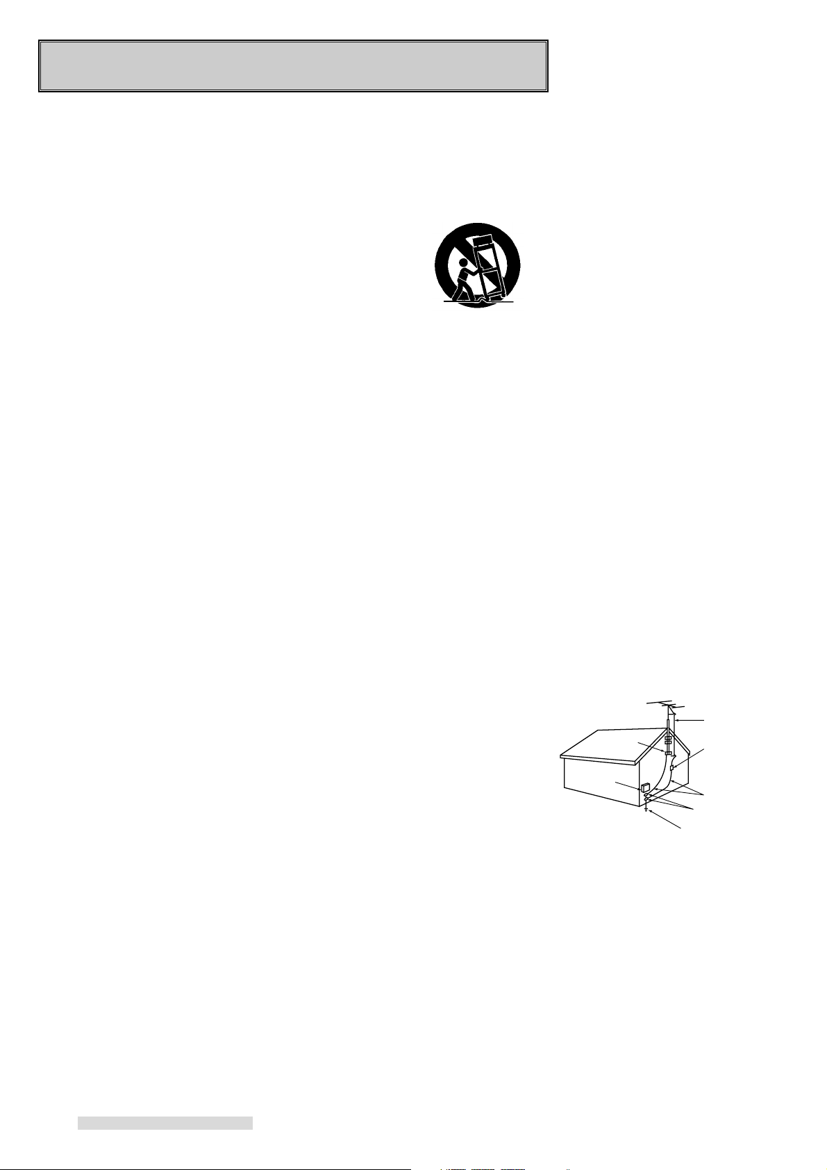
IMPORTANT SAFEGUARDS
ANTENNA
LEAD IN WIRE
ANTENNA
DISCHARGE UNIT
(NEC SECTION 810-20)
GROUNDING
CONDUCTORS
(NEC SECTION 810-21)
GROUND CLAMPS
POWER SERVICE GROUNDING
ELECTRODE SYSTEM
(NEC ART 250, PART H)
GROUND CLAMP
ELECTRIC
SERVICE
EQUIPMENT
NEC – NATIONAL ELECTRICAL CODE
EXAMPLE OF ANTENNA GROUNDING
Please read all these instructions carefully regarding your VCR before you begin operating it.
Follow all warnings and instructions marked on the VCR. Thank you.
1 Read Instructions
All the safety and operating instructions should be read before
the product is operated.
2 Retain Instructions
The safety and operating instructions should be retained for future
reference.
3 Heed Warnings
All warnings on the product and
in the operating instructions
should be adhered to.
4 Follow Instructions
All operating and use instructions
should be followed.
5 Cleaning
Unplug this product from the wall
outlet before cleaning. Do not use
liquid cleaners or aerosol cleaners. Use a damp cloth for cleaning.
6 Attachments
Do not use attachments not recommended by the product manufacturer as they may cause hazards.
7 Water and Moisture
Do not use this product near water — for example, near a bath
tub, wash bowl, kitchen sink, laundry tub, in a wet basement, or
near a swimming pool, and the
like.
8 Accessories
Do not place this product on an
unstable cart, stand, tripod,
bracket, or table. The product
may fall, causing serious injury to
a child or adult, and serious damage to the product. Use only with
a cart, stand, tripod, bracket, or
table recommended by the manufacturer, or sold with the product.
Any mounting of the product
should follow the manufacturer’s
instructions, and should use a
mounting accessory recommended by the manufacturer.
2
9 A product and cart combination
should be moved with care.
Quick stops, excessive force, and
uneven surfaces
may cause the
product and cart
combination to
overturn.
10 Ventilation
Slots and openings in the cabinet
are provided for ventilation and to
ensure reliable operation of the
product and to protect it from
overheating, and these openings
must not be blocked or covered.
The openings should never be
blocked by placing the product on
a bed, sofa, rug, or other similar
surface. This product should not
be placed in a built-in installation
such as a bookcase or rack unless proper ventilation is provided
or the manufacturer’s instructions
have been adhered to.
11 Power Sources
This product should be operated
only from the type of power
source indicated on the marking
label. If you are not sure of the
type of power supply to your
home, consult your product dealer
or local power company. For
products intended to operate from
battery power, or other sources,
refer to the operating instructions.
12 Grounding or Polarization
This product is equipped with a
polarized alternating-current line
plug (a plug having one blade
wider than the other). This plug
will fit into the power outlet only
one way. This is a safety feature.
If you are unable to insert the plug
fully into the outlet, try reversing
the plug. If the plug should still
fail to fit, contact your electrician
to replace your obsolete outlet.
Do not defeat the safety purpose
of the polarized plug.
13 Power-Cord Protection
Power-supply cords should be
routed so that they are not likely
to be walked on or pinched by
items placed upon or against
them, paying particular attention
to cords at plugs, convenience receptacles, and the point where
they exit from the product.
14 Outdoor Antenna Grounding
If an outside antenna or cable system is connected to the product,
be sure the antenna or cable system is grounded so as to provide
some protection against voltage
surges and built-up static
charges.
Article 810 of the National
Electrical Code, ANSI/NFPA 70,
provides information with regard
to proper grounding of the mast
and supporting structure, grounding of the lead-in wire to an antenna discharge unit, size of
grounding conductors, location of
antenna-discharge unit, connection to grounding electrodes, and
requirements for the grounding
electrode.
15 Lightning
For added protection for this product during a lightning storm, or
when it is left unattended and unused for long periods of time, unplug it from the wall outlet and disconnect the antenna or cable system. This will prevent damage to
the product due to lightning and
power-line surges.
Page 5

16 Power Lines
An outside antenna system
should not be located in the vicinity of overhead power lines or
other electric light or power circuits, or where it can fall into such
power lines or circuits. When installing an outside antenna system, extreme care should be
taken to keep from touching such
power lines or circuits as contact
with them might be fatal.
17 Overloading
Do not overload wall outlets, extension cords, or integral convenience receptacles as this can result in fire risk or electric shock.
18 Object and Liquid Entry
Never push objects of any kind
into this product through openings
as they may touch dangerous
voltage points or short-out parts
that could result in a fire or electric shock. Never spill liquid of
any kind on the product.
19 Servicing
Do not attempt to service this
product yourself as opening or
removing covers may expose you
to dangerous voltage or other
hazards. Refer all servicing to
qualified service personnel.
20 Damage Requiring Service
Unplug this product from the wall
outlet and refer servicing to qualified service personnel under the
following conditions:
(a) When the power-supply cord
or plug is damaged.
(b) If liquid has been spilled, or
objects have fallen into the
product.
(c) If the product has been ex-
posed to rain or water.
(d) If the product does not oper-
ate normally by following the
operating instructions. Adjust
only those controls that are
covered by the operating instructions as an improper adjustment of other controls may
result in damage and will often require extensive work by
a qualified technician to restore the product to its normal
operation.
(e) If the product has been
dropped or damaged in any
way.
(f) When the product exhibits a
distinct change in performance – this indicates a need
for service.
21 Replacement Parts
When replacement parts are required, be sure the service technician has used replacement parts
specified by the manufacturer or
have the same characteristics as
the original part. Unauthorized
substitutions may result in fire,
electric shock or other hazards.
22 Safety Check
Upon completion of any service or
repairs to this product, ask the service technician to perform safety
checks to determine that the product is in proper operating condition.
23 Heat
The product should be situated
away from heat sources such as
radiators, heat registers, stoves,
or other products (including amplifiers) that produce heat.
CONDENSATION
Leave the VCR on, without a tape in
it, for 2 hours if the VCR has been exposed to sudden changes in temperature. Sudden temperature changes
cause moisture to form on the metal
parts inside the VCR. This moisture
can cause the tape to stick and damage the head. Leaving the VCR on
for a 2 hour period will dry the inside
of the VCR.
PROTECT THE POWER CORD
Do not damage the power cord. Damage to the power cord may cause a
fire or shock hazard. When unplugging the power cord, please hold it by
the plug and remove it carefully.
DO NOT PLACE HEAVY OBJECTS
ON THE RECORDER
Heavy objects placed on the recorder
will cause damage.
WHEN NOT IN USE
When you finish operating the recorder, always unload the cassette
and turn OFF the VCR POWER.
CARE OF THE VIDEO CASSETTE
TAPES
• Avoid violent vibration or shock.
• Do not place in a location where
strong magnetic fields exist (near a
motor, transformer or magnet).
• Never place or store in direct sunlight.
• Avoid dusty places.
• Place the cassette in the cassette
case and store vertically.
• Never store tape in a high humidity
location.
INFORMATION
This equipment has been tested and found to comply with the limits for a Class B digital device, pursuant to Part 15
of the FCC Rules. These limits are designed to provide reasonable protection against harmful interference in a
residential installation. This equipment generates, uses, and can radiate radio frequency energy and, if not
installed and used in accordance with the instructions, may cause harmful interference to radio communications.
However, there is no guarantee that interference will not occur in a particular installation. If this equipment does
cause harmful interference to radio or television reception, which can be determined by turning the equipment off
and on, try to correct the interference by one or more of these measures:
• Reorient or relocate the receiving antenna
• Increase the separation between the equipment and receiver
• Connect the equipment into an outlet on a different circuit than the receiver is connected
• Consult the dealer or an experienced radio/TV technician for help
Changes or modifications not expressly approved by the party responsible for compliance could void the user’s
authority to operate the equipment. If necessary, consult the dealer or an experienced radio/TV technician for
additional suggestions. You may find this booklet prepared by the Federal Communications Commission helpful:
How to Identify and Resolve Radio-TV Interference Problems. This booklet is available from the US Government
Printing Office, Washington, D.C., 20402, Stock No. 004-000-00345-4.
3
Page 6
Hooking Up Your VCR
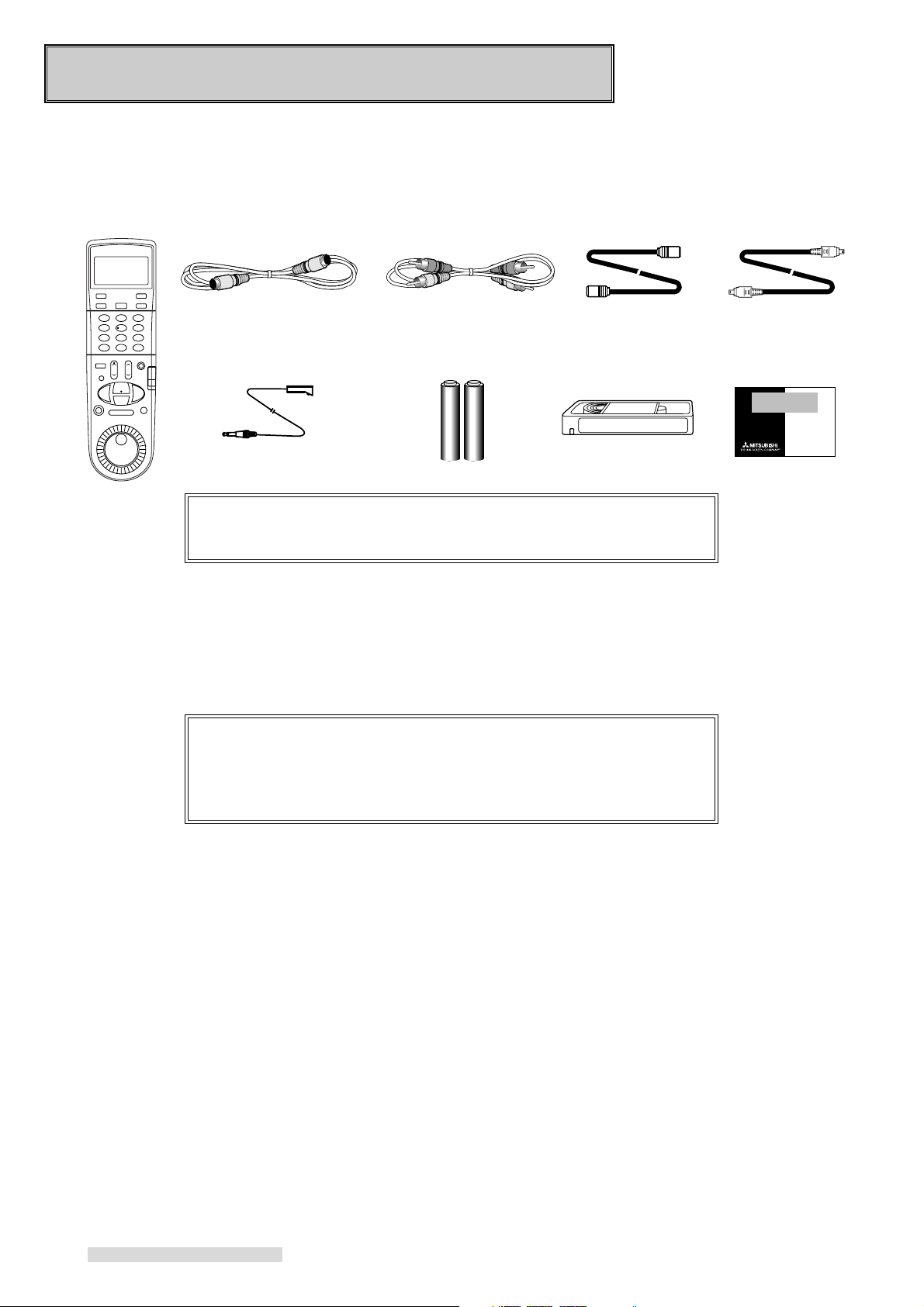
Unpacking Your VCR
As you unpack your new VCR, please make sure the following items are included:
• Remote control
• 1 S-Video cable
• 1 IR emitter
• 1 Audio cable
• 2 "AA" size batteries
• 1 Coaxial cable • IEEE 1394 cable
• D-VHS cassette tape • Registration card
PRODUCT
REGISTRATION
Register and
Win in the
$100,000
Give Away III!
See inside...
IMPORTANT
Never place any heavy objects on top of the VCR. Do not place the
VCR on top of the television as the surface may not be stable.
Choosing a Hookup
The connections shown in this book are general. Individual televisions, stereo systems and satellite receivers can vary
from those shown here. The first diagrams show connections for common equipment. Then, if you are connecting
equipment such as a satellite receiver, an integrated HDTV, an IEEE 1394-equipped HDTV receiver or a Home Theater
receiver, you will also use those diagrams after you have connected the common equipment.
IMPORTANT
To maximize your system for its best performance, your dealer can
help you customize these hookups and sell you any additional connection accessories that may be necessary to match your particular
equipment and antennas.
1 Make a list of each piece of equipment that you want to hook up.
2 If you are connecting several pieces of equipment, you may be using more than one of these diagrams. Using your
list, find EACH of the diagrams you will need to connect all of your equipment. For example, to hook up this VCR, a
TV, a cable box, and a Home Theater receiver, you will use Cable System with Cable Box, and Connecting a Home
Theater receiver.
3 If your TV has audio and video inputs, use the diagrams on page 6 in addition to the connections on the next page.
4
Page 7
Hooking Up Your VCR
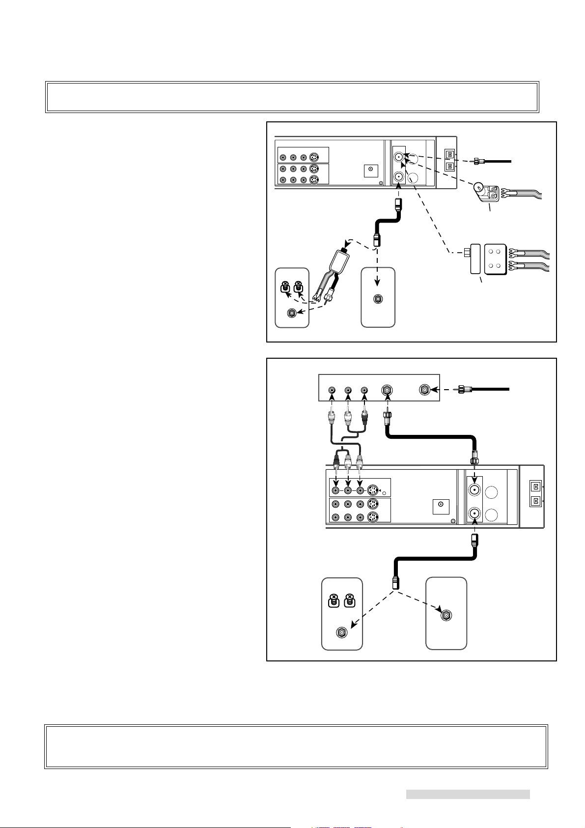
IMPORTANT
You must use one of the connections shown on this page in order to record television or cable programs.
Antenna or Cable System
without Cable Box
Connecting Antenna or Cable
1 Connect antenna or cable from wall outlet to
ANTENNA IN of the VCR.
2 Connect VCR ANTENNA OUT to the TV’s
Antenna jacks (varies by TV).
3 If your TV has audio video inputs, continue with
the connections on the next page. If not, plug
in power cords of VCR and TV.
Antenna or Cable System with
Cable Box
Connecting Cable and Cable Box
1 Connect cable from wall outlet to CABLE IN on
the cable box.
2 Connect OUT (or OUT TO TV) on the cable box
to ANTENNA IN on the VCR.
3 Connect ANTENNA OUT on the VCR to the
TV’s antenna jacks (varies by TV).
VCR Rear Panel
Optional
UHF/VHF Splitter
UHF
VHF
TV Rear Panel
Cable Box Rear Panel
Yellow
optional
audio cable
White
R
VHF/UHF
OR
OUTVIDEO L R
R
L
Red
optional video cable
L
VIDEOAUDIOR
S-VIDEO
L/MONO
IN
ANTENNA
IN
OUT
Optional 300 Ohm to 75 Ohm
supplied
Matching Transformer
coaxial cable
Optional UHF/VHF Combiner
IN
coaxial cable provided
by cable company
1
From Antenna or
Cable wall outlet
OR
OR
x
x
x
x
From Cable
wall outlet
ANTENNA
IN
OUT
4 If your TV has audio video inputs, continue with
the connections on the next page. If not, plug
VCR Rear Panel
in power cords of VCR, TV, and cable box.
5 See page 11 for IR Emitter connection.
If your cable box has audio and video outputs,
follow the additional directions below. You may
need to purchase additional sets of audio/video
cables for this hookup.
UHF
VHF
supplied coaxial cable
OR
VHF/UHF
6 Connect the red and white cable to the AUDIO
IN R (right) and AUDIO IN L (left) on the VCR.
TV Rear Panel
Connect the other end to the cable box’s
AUDIO OUT RIGHT and AUDIO OUT LEFT.
6 Connect the yellow video cable to VIDEO IN on
VCR. Connect the other end to VIDEO OUT on
the cable box.
IMPORTANT
Your TV Owner’s Guide may have additional suggestions for antenna/cable hookups.
If your TV has more than one antenna jack, ask your Mitsubishi dealer for advice on additional accessories.
5
Page 8
Hooking Up Your VCR
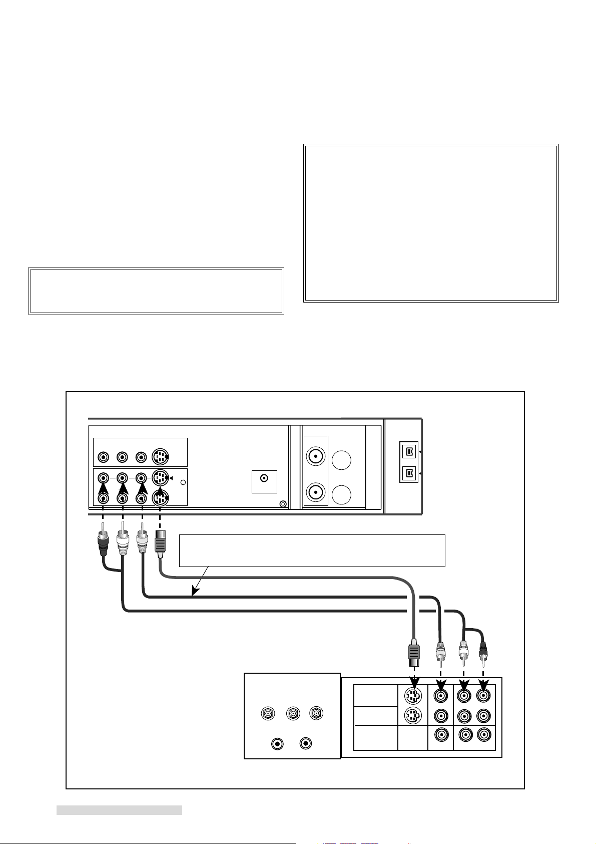
Connections to TV with Audio Video Inputs
Because you purchased a Hi-Fi VCR, you will want to
take advantage of its superior sound capability and
connect it to a stereo TV system with audio and video
inputs. This connection also helps maintain the best
picture quality.
1 Connect the red and white audio cable to AUDIO
OUT R (right) and AUDIO OUT L (left) on the VCR.
Connect the other end to the TV’s AUDIO INPUT
RIGHT and AUDIO INPUT LEFT. Match the colors of
the connectors to the cables.
2 Connect the S-video cable to S-VIDEO OUT on VCR.
Connect the other end to S-VIDEO INPUT on the TV.
IMPORTANT
If your TV does not have S-Video connections, use
optional yellow video cable in step 2.
3 Set the RF converter to OFF. See page 61 for
instructions on this setting, which can be done at a
later time.
IMPORTANT
Your TV Owner’s Guide may have additional suggestions for audio video hookups.
To connect your VCR to a mono (non-stereo) TV,
connect only the white AUDIO OUT L of the VCR
and the white AUDIO INPUT of the TV. Since the
TV is not stereo, you cannot take advantage of your
VCR’s Hi-Fi stereo sound.
If you have an older TV without audio video inputs,
simply connect only the antenna or cable as shown
on the previous page.
VCR Rear Panel
VIDEO S-VIDEO
AUDIORL
L
R
Red
White
Yellow
OUT 1
If you connect an S-video cable, there is no need to connect
a yellow video cable. If you do so, it may cause interference of
the picture depending on your TV.
supplied S-video cable
optional video cable
supplied audio cable
TV Rear Panel
INPUT-1
Yellow
White
Red
L
R
R
INPUT-2
OUTPUT
MONITOR/TUNER
S-VIDEO
VIDEO
L (MONO) R
AUDIO
6
Page 9
Hooking Up Your VCR
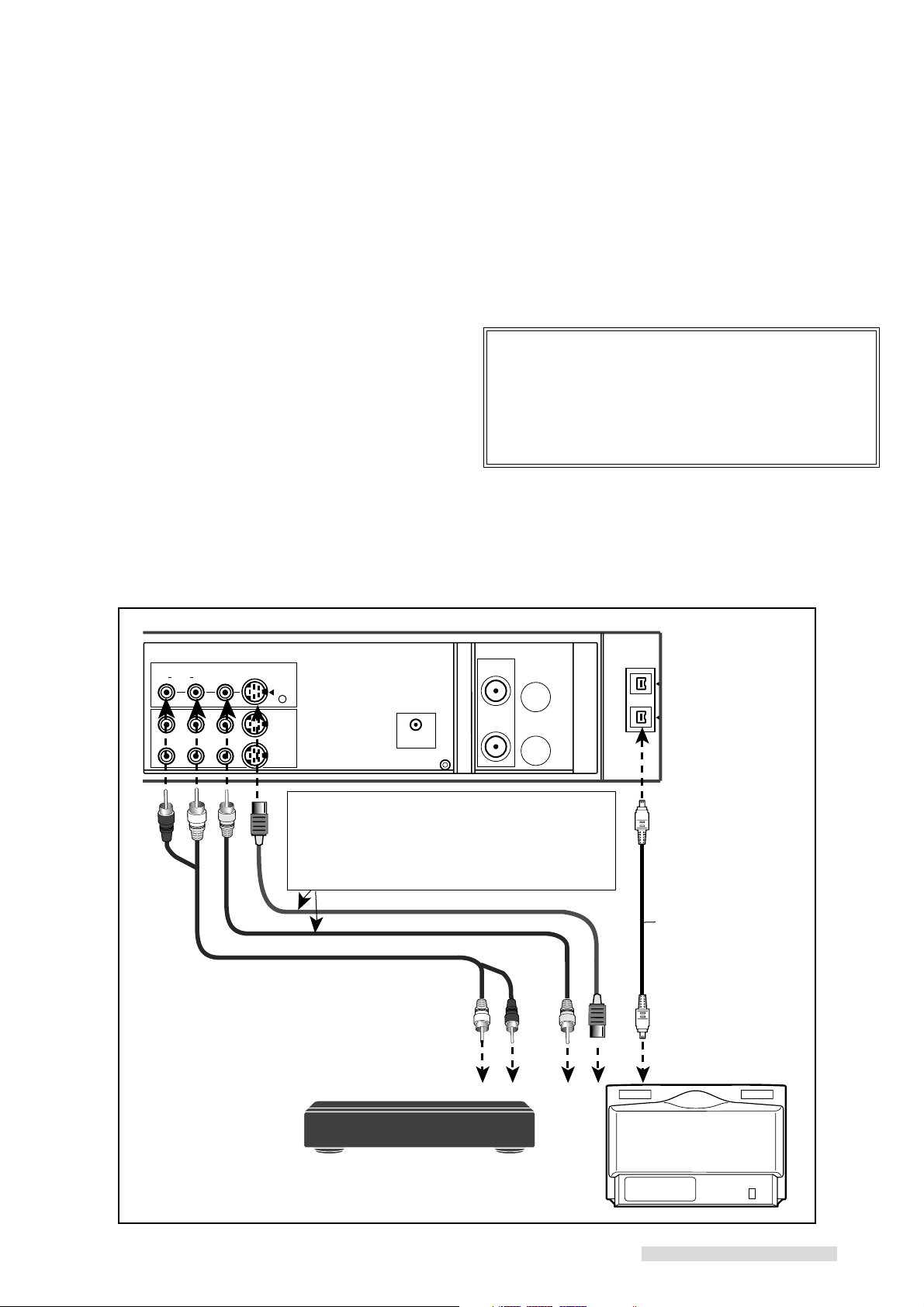
Connections to Integrated HDTV or IEEE 1394-equipped HDTV Receiver
If you connect the HS-HD2000U to an integrated HDTV
or an IEEE 1394-equipped HDTV receiver with an IEEE
1394 cable, you can record digital broadcasts in D-VHS
format, which records digital broadcasts as digital signals,
so programs can be recorded as is with no loss of quality.
And this connection also makes it possible to playback a
recorded digital signal in D-VHS format.
1 Connect the supplied IEEE 1394 cable to IEEE 1394
INTERFACE on the HS-HD2000U. You can connect
either of the two IEEE 1394 INTERFACE terminals.
Connect the other end of this cable to IEEE 1394
INTERFACE terminal on the TV or the receiver.
When you want to record digital broadcasts in analog (SVHS, S-VHS ET or VHS) format, follow the steps 2 and 3
below.
2 Connect the red and white audio cable to AUDIO IN
R (right) and AUDIO IN L (left) on the VCR. Connect
the other end to the TV or the receiver’s AUDIO
OUTPUT RIGHT and AUDIO OUTPUT LEFT. Match
the colors of the connectors to the cables.
VCR Rear Panel
3 If your TV or receiver has an S-VIDEO OUTPUT,
connect the S-Video cable to S-VIDEO IN on the
VCR. Connect the other end to S-VIDEO OUTPUT
on the TV or receiver.
If your TV or receiver does not have an S-VIDEO
OUTPUT, connect the yellow video cable to VIDEO
IN on the VCR. Connect the other end to VIDEO
OUTPUT on the TV or receiver.
IMPORTANT
You may need to purchase additional sets of audio
cable and S-video/video cable for this hookup.
Refer to your integrated HDTV or IEEE 1394equipped HDTV receiver owner’s guide for this
connections.
Red
AUDIOR L/MONO
R
White
VIDEO S-VIDEO
L
Yellow
IN 1
If your TV or receiver has an S-VIDEO OUTPUT,
connect the VCR and the TV or receiver with an
S-Video cable.
If your TV or receiver does not have an S-VIDEO
OUTPUT, connect the VCR and the TV or receiver
with a yellow video cable.
White
Red
Yellow
L
R
R
IEEE 1394-equipped
HDTV receiver
OR
IEEE 1394
INTERFACE
supplied
IEEE 1394 cable
integrated HDTV
7
Page 10
Hooking Up Your VCR
Notes about IEEE 1394 network
The IEEE 1394-equipped devices that are available to be connected to the HS-HD2000U are an integrated HDTV, an
IEEE 1394-equipped HDTV receiver or a D-VHS VCR. The data may not be sent/received correctly if you are connecting
IEEE 1394-equipped devices other than Mitsubishi integrated HDTV or Mitsubishi D-VHS VCR.
You cannot send/receive the data of digital video equipment (for example, digital video camera) or a personal computer
because the format is different from that of the HS-HD2000U.
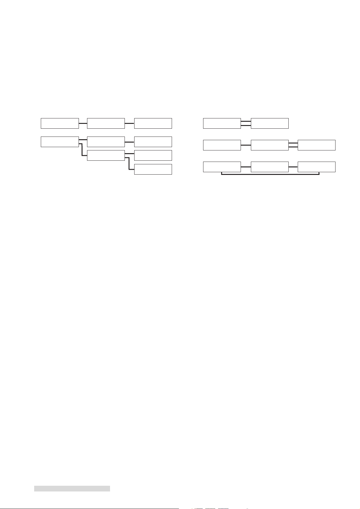
Be sure not to connect the IEEE 1394 in a loop, as shown below.
CORRECT
CORRECT
IEEE 1394-equipped
device
IEEE 1394-equipped
device
IEEE 1394-equipped
device
IEEE 1394-equipped
device
IEEE 1394-equipped
device
IEEE 1394-equipped
device
IEEE 1394-equipped
device
IEEE 1394-equipped
device
IEEE 1394-equipped
device
INCORRECT
INCORRECT
INCORRECT
IEEE 1394-equipped
device
IEEE 1394-equipped
device
IEEE 1394-equipped
device
IEEE 1394-equipped
device
IEEE 1394-equipped
device
IEEE 1394-equipped
device
IEEE 1394-equipped
device
IEEE 1394-equipped
device
When you connect more than one IEEE 1394-equipped devices, turn the power off when they are not being used
because leaving the unused devices turned on may cause a lack of memory and may interfere with the correct transmission of signals. However some IEEE 1394-equipped devices cannot receive or send data when it is turned off, so
refer to your device owner’s guides.
While using the IEEE 1394-equipped device, do not plug in/off the IEEE 1394 cable or turn the power on/off of the
unused devices. When you unplug the IEEE 1394 cable and connect it again, leave it unplugged for a few seconds and
then connect again.
The maximum transmit speed of the IEEE 1394 INTERFACE on the HS-HD2000U is 400Mbps. This speed may be
slower when you connect the device with its transmit speed is different from this VCR.
8
Page 11
Hooking Up Your VCR
Connections to Satellite Receiver
If you have an Mitsubishi DSS®, RCA DSS®, Sony DSS®,
Toshiba DSS®, Panasonic DSS®, Hughes DSS®,
PRIMESTAR®, or DISH Network™ satellite system, you
can connect the satellite receiver to your VCR and then
set up the VCR to change the channels of the satellite
receiver. This will allow you to program your VCR to
make unattended recordings from several different
satellite channels.
1 Connect the red and white audio cable to AUDIO
OUT R and AUDIO OUT L on the satellite receiver.
Connect the other end to the AUDIO IN R and AUDIO
IN L on the back of the VCR. Match the colors of the
connectors to the cables.
2 Connect the S-video cable to S-VIDEO OUTPUT on
the satellite receiver. Connect the other end to the SVIDEO IN on the back of the VCR.
If your satellite receiver does not have S-VIDEO
OUTPUT, connect the video cable to VIDEO
OUTPUT on the satellite receiver. Connect the other
end to the VIDEO IN on the back of the VCR.
3 See page 11 for IR Emitter connection.
connecting both a satellite receiver and a cable box
with audio video outputs
IMPORTANT
You cannot connect both a satellite receiver and a
digital cable box.
You may need to purchase an audio cable and an Svideo cable for this hookup.
If possible, you should have connected your VCR to
your TV with an S-Video cable. It will allow you to
watch the satellite video signal on your TV even
when the VCR is off if you set the Rear S-through in
the S-VHS Set-Up menu to ON.
If you connect your VCR to your TV with a standard
video cable, you will have to turn the VCR on to
watch the video signal from the satellite receiver.
You will be able to hear the audio signal from your
satellite receiver both when the VCR is on and off.
When you connect a satellite receiver to the S-video
input on the back of the VCR, you have to set the
Rear S-input in the S-VHS Set-Up menu to ON.
Refer to your Satellite Receiver Owner’s Guide for
Satellite dish to Satellite receiver connections, as
well as other possible video connections to your TV.
1 Connect the satellite receiver to the audio video
inputs on the back of the VCR as shown.
2 Connect the cable box to the audio video inputs on
the front of the VCR.
VCR Rear Panel
Red
VIDEOAUDIOR
L/MONO
L
R
White
S-VIDEO
IN
1
optional
S-video cable
Yellow
Connect it only if the satellite
receiver does not have S-Video
Output.
DSS® is a registered trademark of DirecTV, Inc.
PRIMESTAR® is a registered servicemark of PRIMESTAR Partners LP.
DISH Network™ is a registered trademark of EchoStar Communications Corp.
Satellite Receiver Rear Panel
S-VIDEO
VIDEO L RAUDIO
OUT
Yellow
OUT
R
L
White Red
optional video cable
optional audio cable
9
Page 12
Hooking Up Your VCR
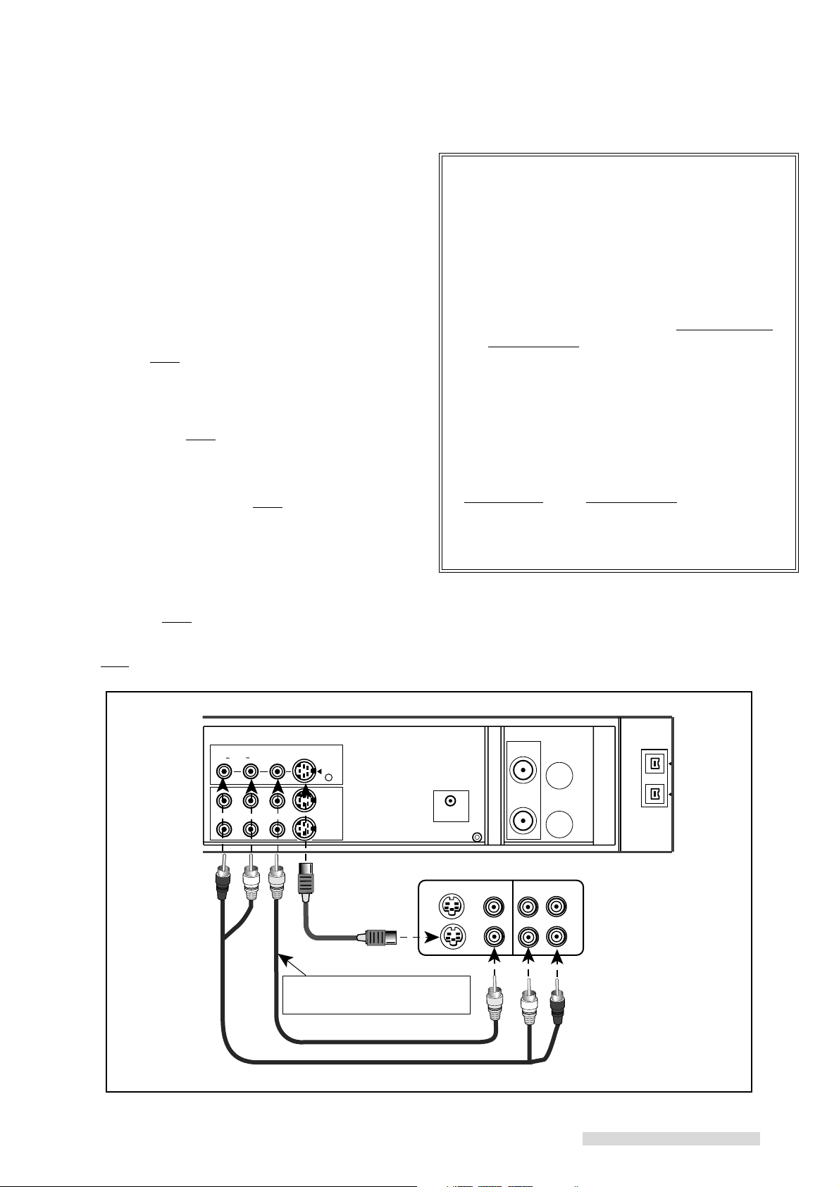
Connections to Home Theater Receiver
You may wish to connect your VCR to a Home Theater
Receiver so that you can take advantage of the Surround
Sound audio recordings that are common with many
movies. Home Theater Receivers will often control both
the sound that is heard from the speakers and the picture
shown on your TV. Below is the basic connection between your VCR and Home Theater Receiver. If you use
this connection, you will not use Connections to TV with
Audio Video Inputs.
1 Connect the red and white audio cables to AUDIO
OUT R and AUDIO OUT L on the VCR. Connect the
other end to the VCR 1 AUDIO INPUT R and AUDIO
INPUT L on the Home Theater Receiver.
2 Connect an S-video cable to S-VIDEO OUT on the
VCR. Connect the other end to the VCR 1 S-VIDEO
INPUT on the Home Theater Receiver.
TV Rear Panel
INPUT 1
3 Connect an S-video cable to the MONITOR S-VIDEO
OUTPUT of the Home Theater Receiver. Connect
the other end to the S-VIDEO INPUT on the back of
the TV.
IMPORTANT
If either your Home Theater Receiver or TV does
not have S-Video connections, use standard yellow
video cables in step 2 and 3.
4 See your Home Theater Receiver Owner’s Guide for
information concerning audio connection between TV
and Home Theater Receiver, or additional hookups
and operations.
IMPORTANT
You may need to purchase additional sets of audio
video cables for this hookup.
Home Theater Receiver Rear Panel
VCR2 MONITOR DVDVCR 1
VCR2 MONITORVCR 1
White
S - VIDEO
OUT IN OUT IN OUT
VIDEO
OUT IN OUT IN OUT
AUDIO
L
R
R
L
OUT IN OUT IN IN
VCR 1 VCR 2 TV
R
Red
VCR Rear Panel
VIDEO S-VIDEO
AUDIORL
OUT 1
S-VIDEO
R
R
L (MONO)
VIDEO
AUDIO
L
10
Red
R
L
White
Page 13
Hooking Up Your VCR
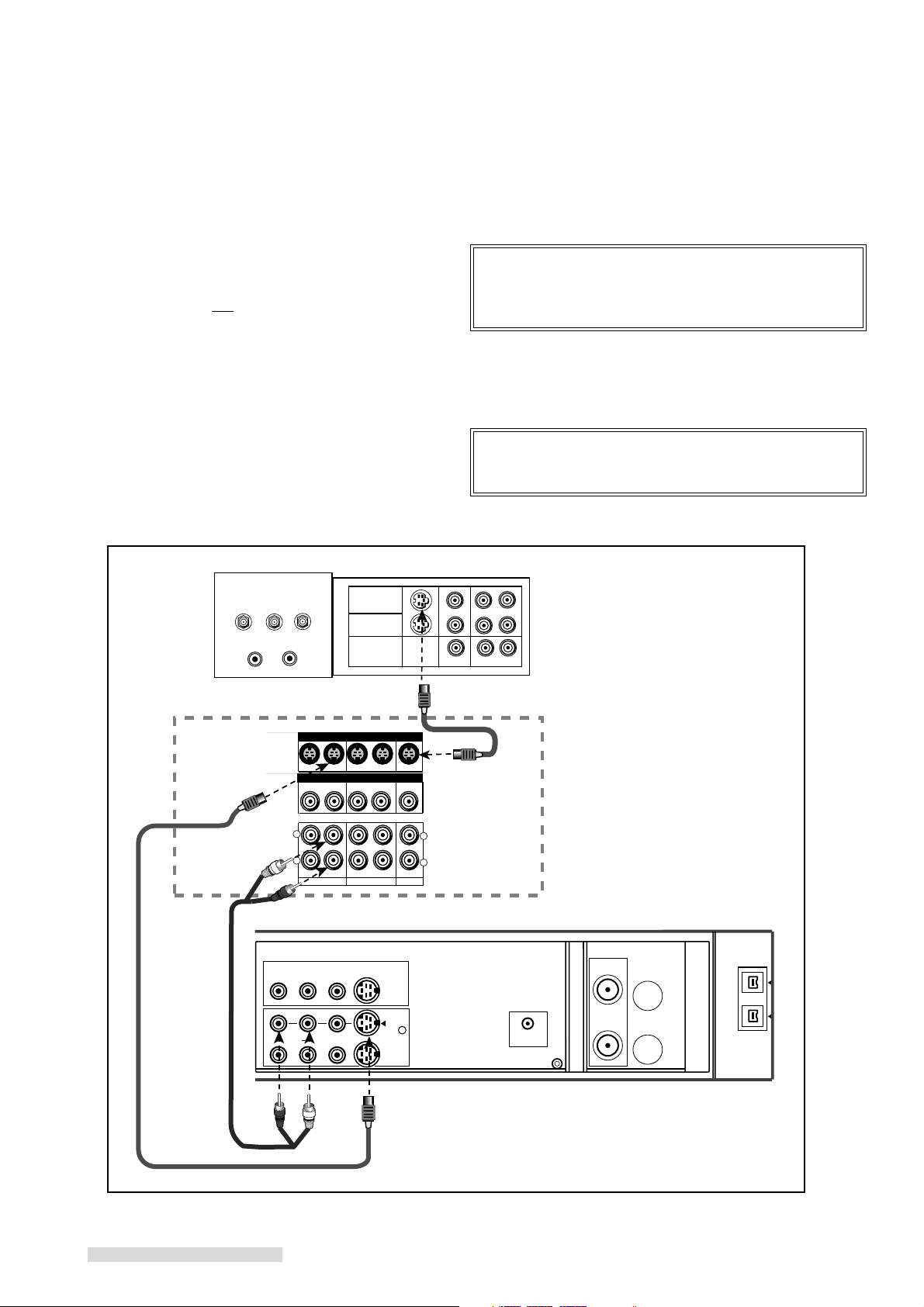
Connections to IR Emitter
Your VCR will be able to send remote control channel
changing commands to your compatible cable box or
satellite receiver. The VCR uses the IR Emitter to send
these commands in the same way as when you use the
hand held remote that came with the cable box or receiver.
1 Connect the supplied IR Emitter to CONVERTER
BOX CONTROL on back of the VCR.
2 Run the wire under or along side the cable box or
satellite receiver and place the end in front of the
cable box and/or satellite receiver.
3 Use the double stick tape to secure the end of the
emitter in the proper place.
VCR Rear Panel
CONVERTER
BOX CONTROL
IMPORTANT
If you connect both a cable box and satellite receiver, place the IR Emitter to face the remote
control window (sensor) in the front of both. If you
cannot place it this way, you can purchase a dual IR
Emitter from your Mitsubishi dealer.
Cable Box or Satellite Receiver
IR Emitter
11
Page 14
Playback
PWR.
HS
STD
VCR
HMS
Setting Up Your VCR to Playback/Recording the
Digital Broadcast in D-VHS Format
1 Make sure that your VCR and the integrated HDTV or the IEEE 1394-equipped
HDTV receiver is connected with an IEEE 1394 cable.
2 Turn on the IEEE 1394-equipped HDTV receiver.
3 Turn on your TV and switch the input of the TV to the correct input of the IEEE
1394-equipped HDTV receiver.
4 Press POWER on the VCR to turn the power on.
To go back to viewing the picture from the TV, set your TV input to the previous
ANTENNA input position.
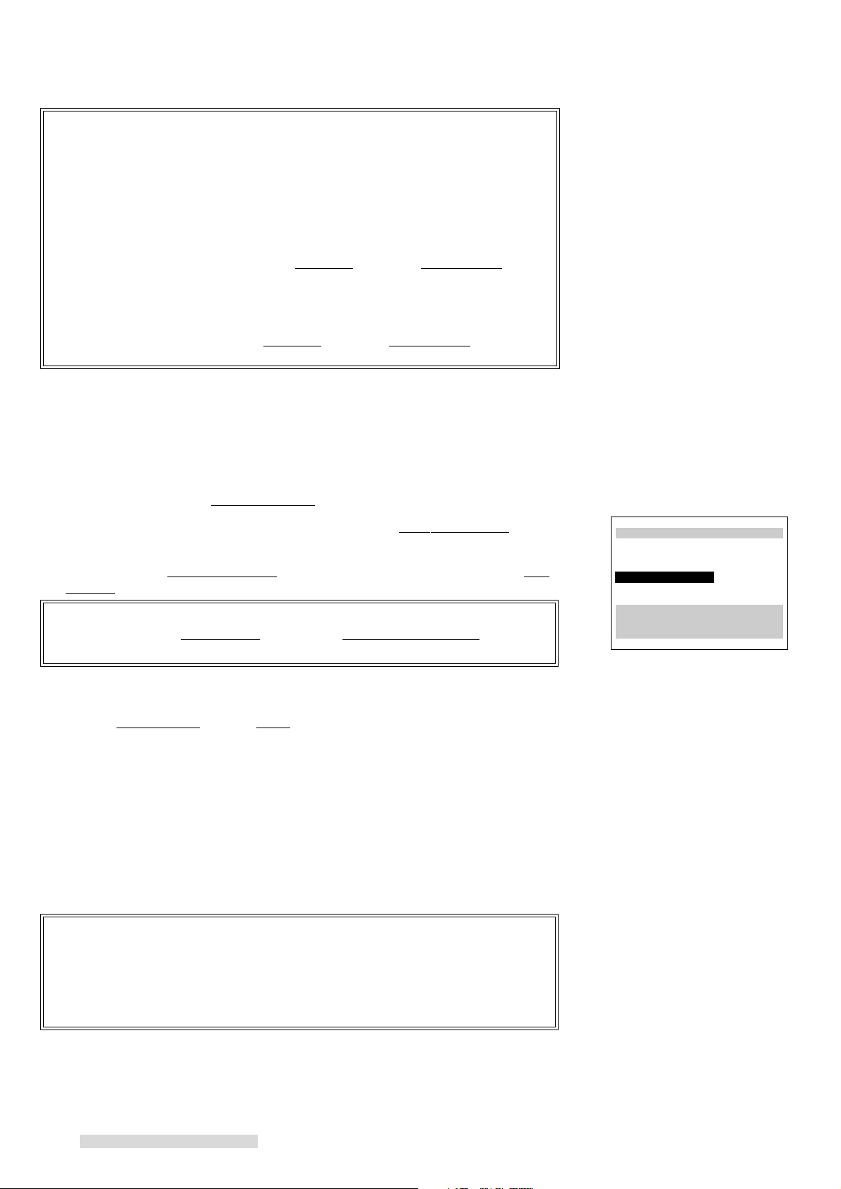
If you do not switch the integrated HDTV or the IEEE 1394-equipped HDTV receiver to the correct external input, the screen to the right will be displayed on the
screen when you try to watch a digital broadcast.
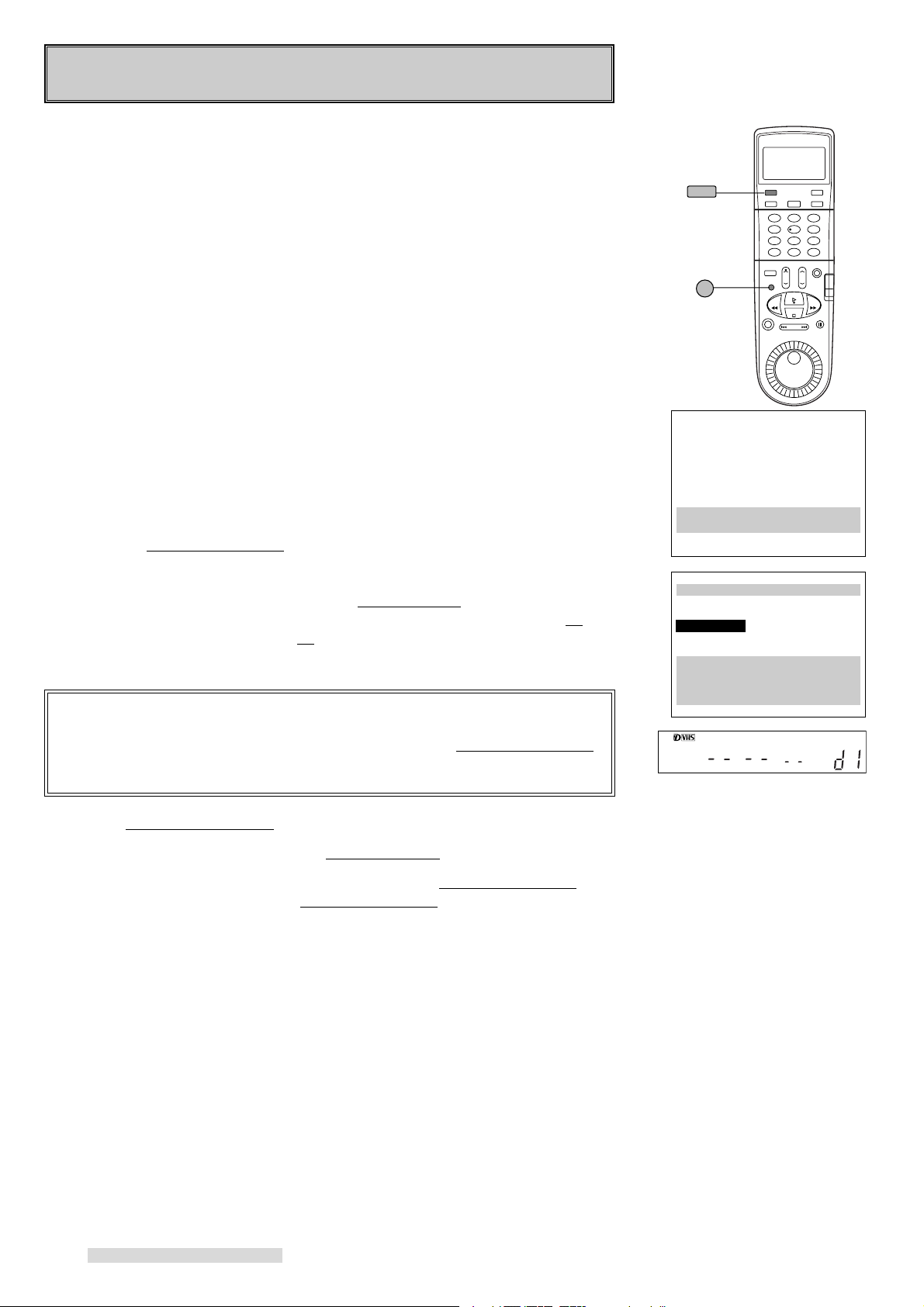
1394 connection list
When you connect an integrated HDTV, an IEEE 1394-equipped HDTV receiver or
a D-VHS VCR to the HS-HD2000U, you can see the list of connected TV, receiver
or VCR on the 1394 connection list menu (up to 5 devices). The integrated HDTV
and the IEEE 1394-equipped HDTV receiver will display as TUNER and the D-VHS
VCR will be shown as VCR. For the device which was connected to the HSHD2000U before but now it is not connected, lost connection will be displayed.
The device which was first connected to the HS-HD2000U will be shown as d1,
and connected fifth will be shown as d5. When you want to remake the list, press
CANCEL on the VCR remote control. In this case, the order of the devices on the
list will be changed.
IMPORTANT
When you connect Mitsubishi integrated HDTVs WS-55859, WS-65869, WS55909, WS-65909 or WS-73909, they will not appear in 1394 connection list
menu. When you use these TVs, they will control the HS-HD2000U. So to
use the function of the HS-HD2000U, use the TV to operate the VCR.
VCR POWER
IEEE 1394
INPUT
This is a digital
recording.
You cannot view it
through this input.
Please select IEEE1394
connection.
ƒ1394 connection list
d1 TUNER lost connection
d2 TUNER lost connection
d3 TUNER now connecting
d4 VCR now connecting
Press CANCEL to renumber
Use ADJUST to select,
and ENTER.
Press MENU to go back.
displaying 1394 connection list
1 Press MENU on the remote control. VCR Main Menu comes up.
2 Turn the ADJUST dial on the remote control to select 1394 connection list.
Turn the shuttle ring to the right. 1394 connection list menu appears.
Setting Up Your VCR to Playback/Recording the
Tape in Analog (S-VHS/S-VHS ET/VHS) Format
The first thing you need to do is set up your VCR so that you can see the picture
coming from the VCR. It’s important to take a few minutes to set up your VCR
correctly before you try to use it. Based on the type of TV that you have, choose
one of the following:
TV with Audio/Video Inputs
1 Turn on your TV and switch it to the correct external input. For most Mitsubishi
TVs, this means pressing the TV’s INPUT button until you see the words Ext-1
or Input-1 on the screen. If you do not have a Mitsubishi TV, please refer to
your TV Owner’s Guide for this procedure.
2 Turn the VCR on by pressing POWER.
12
Page 15
Playback
3 You are now watching the VCR’s picture. To go back to viewing the picture
from the TV, press the TV’s INPUT button to go back to the previous ANTENNA
input position.
4 Later, you should turn the RF converter OFF by following instructions on page
61.
If your system includes a home theater receiver or an A/V receiver, refer to your
home theater receiver’s owner’s guide.
TV without Audio/Video Inputs
If your TV does not have separate audio/video inputs, then your VCR will need to
convert the VCR’s picture to channel 3 or 4. This is called the video channel. The
factory has already selected channel 3; however, if it is a broadcast channel in
your area, then you will need to change this to channel 4. To make this change:
set up
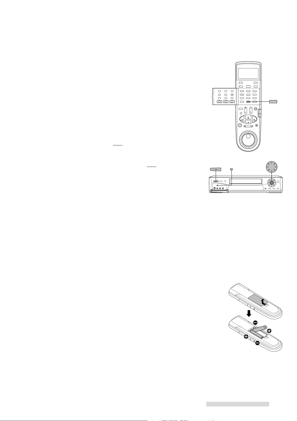
1 To choose channel 4: with VCR power OFF, turn the front panel jog dial disk
clockwise while holding down the SP/EP button on the front panel. Ant ch 4
will display on the front panel and the VCR will send signals on channel 4.
If needed, to return to channel 3: with the VCR turned OFF, turn the jog dial
counter-clockwise while holding down the SP/EP button on the front panel.
Ant ch 3 will display.
2 Turn the VCR on by pressing POWER.
operating
3 Check to see if the VCR light on the front panel display is lit. If it is not, press
VCR/TV on the remote control until the VCR light appears on the front panel.
This light must be on when you watch a video tape or use the VCR menus.
The VCR light will turn on automatically when you play a tape or use the VCR
menus when the RF converter is set to ON. See page 61.
4 Turn on the TV and change the TV to the video channel (3 or 4). You are now
watching the VCR’s picture.
POWER
VCR/TV
JOG/CHANNEL
SP/EP
To watch a channel that is different than the channel your VCR is recording, the
VCR light must be off. The VCR/TV button turns this light on and off.
Operating Your Remote Control
Installing the Batteries
1 To remove the back cover, press the ridged area gently, then push the cover in
the direction of the arrow and lift.
2 Load the batteries, making sure the polarities (+) and (–) are correct.
This is marked inside the battery compartment.
Next, you need to tell the remote control to operate the VCR, not the TV.
Operating the VCR with the Remote Control
The HS-HD2000U has two VCR remote control operational settings: VCR-A and
VCR-B. The HS-HD2000U is pre-set to VCR-A setting. See page 65 for information about VCR operational setting.
1 Set the VCR/TV slide switch on the remote control to VCR position. This “tells”
the remote that you want to control the VCR.
Now your remote is ready to operate your HS-HD2000U. If the VCR does not
respond to the remote, please see page 65.
13
Page 16
CORRECT
INCORRECT
STOP
PLAY
PLAY
STOP
Playback
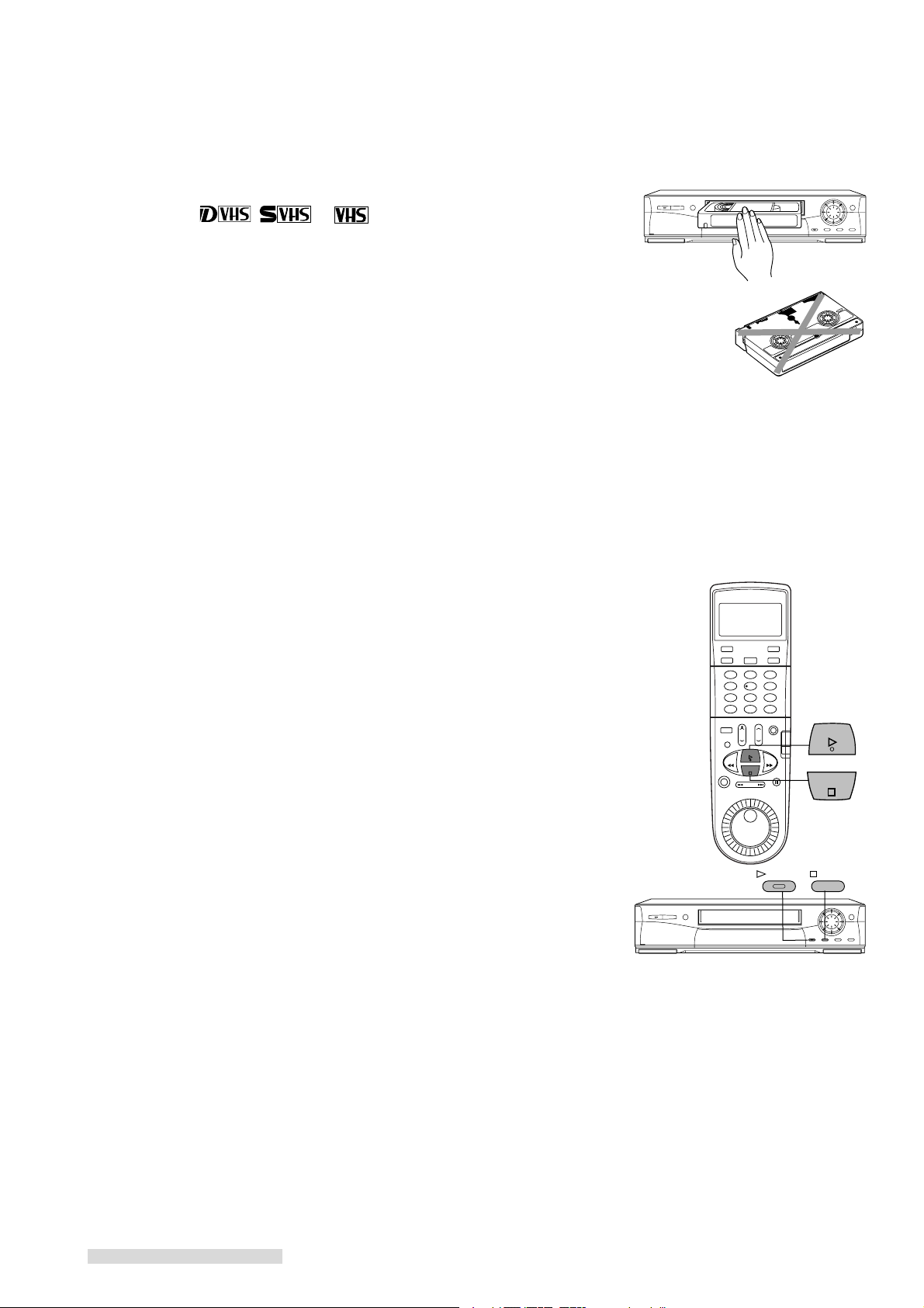
Loading a Tape
Tapes can be loaded into your VCR as long as the VCR is plugged in. Even when
the VCR POWER is off, loading a tape will automatically turn the VCR on. Use
only tapes that have a , or label.
1 Hold the tape so that the long narrow edge with the contents label faces you.
The other edge is hinged and should face the VCR. The plastic window that
shows the videotape should face up.
2 Gently insert the tape evenly into the cassette slot until the VCR automatically
takes it in.
If the VCR will not automatically take the tape in, press EJECT and try again.
Your VCR will eject the tape if it is loaded improperly. If the VCR ejects the tape,
remove the tape, check to see that the contents label is facing you, that the geared
tape reels are facing down, wait a few seconds, and try again.
Playing a Tape
Playing a Tape Recorded in D-VHS Format
1 When you connect an integrated HDTV or IEEE 1394-equipped HDTV receiver
which is capable of controlling the VCR:
Operate your TV or receiver to playback the tape. Refer to the TV or receiver
owner’s guide for this procedure.
When you connect an integrated HDTV or IEEE 1394-equipped HDTV receiver
which is not capable of controlling the VCR:
Set the connection setting of your TV or receiver to select the HS-HD2000U.
Refer to the TV or receiver owner’s guide for this procedure.
And then press PLAY on the front panel or the remote control of the VCR.
You can stop playing by pressing STOP.
It will take a few seconds to display the playback picture. A mosaic noise, still or
black picture will appear until the correct picture comes on. When the VCR
reaches the end of the tape, it will automatically rewind to the beginning of the tape
and stop.
When you playback the end of a recording, the point where the recording mode
changes or a broken part of the tape, a mosaic noise, still or black picture may
appear.
The tape recorded in D-VHS format on other VCR may not be played back correctly on this VCR.
Playing a Tape Recorded in Analog (S-VHS/S-VHS ET/VHS) Format
1 Press PLAY on the front panel or the remote control.
The VCR will automatically play the tape at the correct speed. When the VCR
reaches the end of the tape, it will automatically rewind to the beginning of the tape
and stop.
You can stop playing by pressing STOP.
14
Page 17
JOG/CHANNEL
SP/EP
PAUSE
FF
REW
PAUSE
EJECT
EJECT
Playback
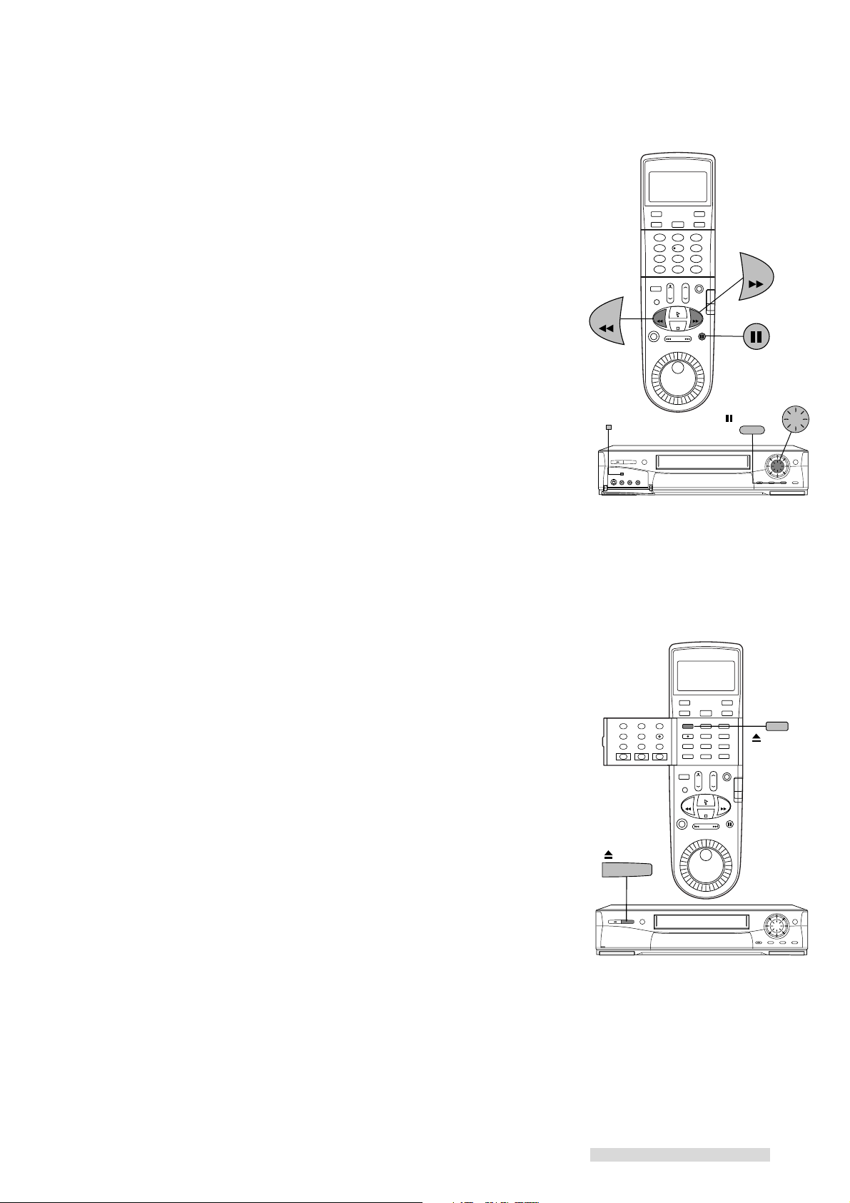
Using Basic Playback Controls
Rewinding a Tape
While the tape is stopped, press REW on the remote control or turn the shuttle ring
on the front panel to the left.
Fast Forwarding a Tape
While the tape is stopped, press FF on the remote control or turn the shuttle ring on
the front panel to the right.
Speed Search with Picture
While the tape is playing, press FF on the remote control or turn the shuttle ring on
the front panel to the right for forward speed search with picture, or press REW on
the remote control or turn the shuttle ring on the front panel to the left for reverse
speed search. See page 56 for additional information on searching techniques.
Pausing a Tape
While the tape is playing, press PAUSE on the remote control or on the front panel
to freeze the picture on the screen.
Press PAUSE a second time to return to normal play.
If you leave the VCR in pause for more than 5 minutes, the VCR will automatically
stop to prevent damage to the tape.
When pausing a tape recorded in D-VHS format, a black picture may appear
before the still picture appears depending on the integrated HDTV or IEEE 1394equipped HDTV receiver.
Unloading a Tape
1 Press EJECT on the front panel or on the remote control. If the VCR POWER
is off, the VCR will turn on, eject the tape, then turn off.
2 Remove the tape.
Using Repaired Tapes
We recommend that you take any broken or torn tapes to a professional for repair.
If you repair a torn tape with improper materials, you could damage your VCR
when you play the tape.
Head Cleaning
Your VCR automatically cleans the head and the drum of the VCR whenever you
load a tape. If you see mosaic noise, still or black picture during D-VHS playback,
or “noise” or snow during analog playback, eject the tape, re-load the tape, then
wait 3 or 4 seconds. Repeat this process several times to improve the picture.
15
Page 18
Setting Up Your VCR
Your VCR comes with Mitsubishi’s exclusive on-screen operating
system. This system has been developed to simplify the operation of your VCR
with clear, easy-to-understand language and design.
Before your VCR can receive television channels or you can program your VCR to
record, you need to memorize all of the channels you can receive into your VCR
and set the clock. Additionally, if you are using a satellite receiver, you need to do
a first time setup to memorizing satellite brand code. Fortunately, your VCR makes
this an easy process with our menu system.
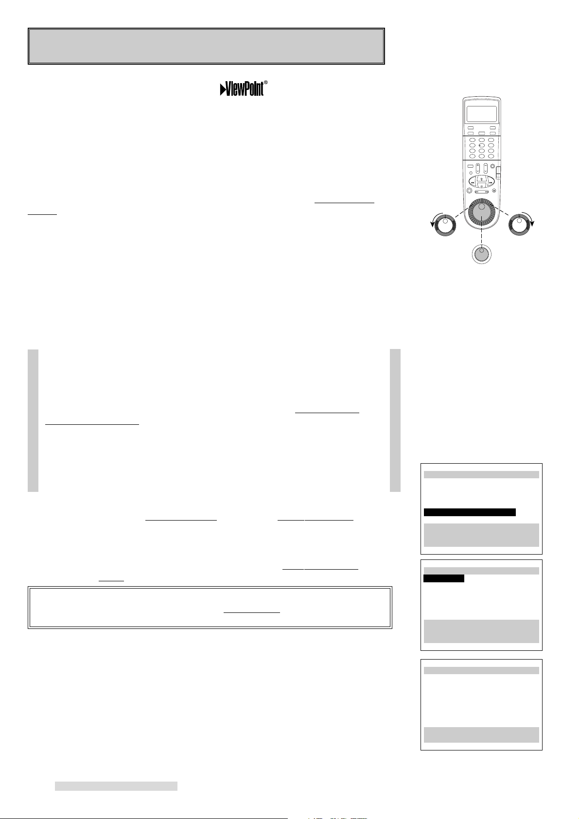
When using the on-screen menus, use the JOG/SHUTTLE control on the remote
control, not the front panel. Use the ADJUST dial to move the highlight bar up or
down and to change the setting of selected features. Turn the SHUTTLE ring to
the right to enter a selection or adjustment (the ENTER button may also be used
for this). Turn the shuttle ring to the left to cancel or clear a setting (the CANCEL
button may also be used for this).
Using ALLSET™ to Set Up Your VCR Automatically
ALLSET will automatically set the clock, memorize all of the television stations
available to you and set the VCR Plus+ guide channel numbers.
You need to manually set the brand code for the satellite receiver.
If your local cable company scrambles some or all stations, and/or requires you
to use a cable box, then your ability to program channels would normally be
limited. The cable box receives all of your channels, then sends only one to
your TV and your VCR, usually on channel 3 or 4.
If you are required to use a cable box, you should choose Cable box only or
Digital Cable box only option in step 4 on the next page and turn the cable box
on. Your HS-HD2000U will use its Converter Box Control technology to
change the channels on the cable box. Make sure you have properly placed
the IR Emitter (see page 11).
If your cable box or cable system seems incompatible with your new VCR, call
your cable company. They may be able to provide solutions to your problems.
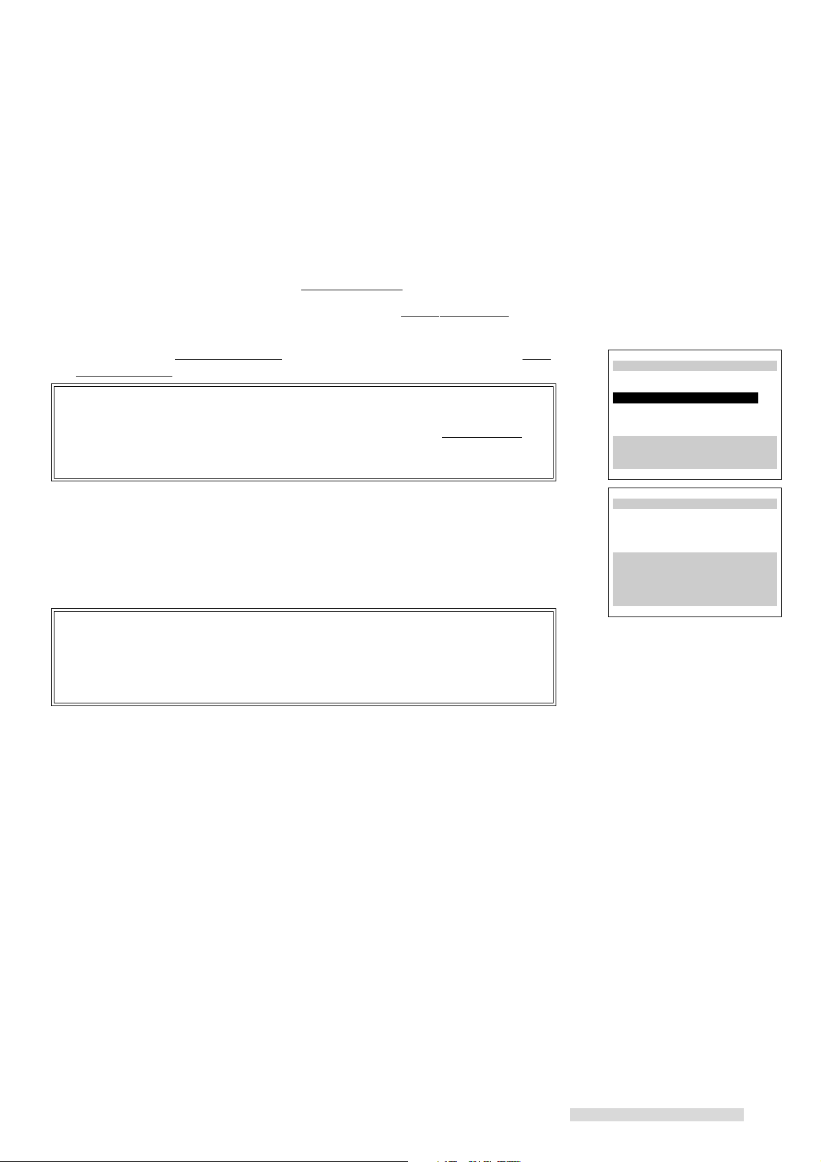
1 Make sure you are viewing the picture coming from your VCR. Press MENU
on the remote control. VCR Main Menu comes up. If First Time Set-Up is not
highlighted, use the ADJUST dial on the remote to highlight it.
Turn left
to Cancel
ADJUST
Turn right
to Enter
A special note to cable box
subscribers
ªVCR Main Menu
¬Program to record
ƒ1394 connection list
√Customize choices
»S-VHS Set-Up
ƒFirst Time Set-Up
Use ADJUST to select,
and ENTER.
Press MENU to exit menus
2 Turn the shuttle ring on the remote control to the right. First Time Set-Up menu
will appear. AllSet will be highlighted. Turn the shuttle ring to the right.
IMPORTANT
If you are recording, playing back a tape, Not available will flash and an error
message will appear. To correct this, stop the tape.
3 You will see the AllSet explanation screen. Turn the shuttle ring to the right.
16
ƒFirst Time Set-Up
∆AllSet
≈Set the clock
«Add/delete channels
±Sat.receiver (OFF)
ππππππππππππππππππππππππ
Use ADJUST to select,
and ENTER.
Press MENU to go back.
∆AllSet
Fully Automatic Setting
Clock
VCR Plus+ Guides
Channel memory
Press ENTER to continue.
Press MENU to go back.
Page 19
∆AllSet
What type of sources are
connected to the VCR?
’Cable
”Cable box only
”Digital cable box only
”Indoor/outdoor ant.
Use ADJUST to select,
and ENTER.
Press MENU to go back.
Setting Up Your VCR
4 You will see the menu for sources connected to the VCR. Using the list below as
a reference, turn the ADJUST dial to select the kind of antenna you connected.
• Cable if you have standard cable service without a cable box, use a cable
box with an A/B switch, or your cable box is not remote controllable
• Cable box only if you use a standard cable box
• Digital cable box only if you use a digital cable box
• Indoor/outdoor ant. if you use rabbit ears type or roof mounted type antennas
After you have selected, turn the SHUTTLE ring to the right.
If you choose Cable or Indoor/outdoor ant.
An on-screen message and the front panel display of your VCR will show you that
the VCR is memorizing the stations you can receive. After the VCR has programmed all the channels, you will see the screen for entering the zip code. Go to
step 10 in this section.
If you choose Cable box only or Digital cable box only
You need to tell the VCR which manufacturer makes your cable box or digital cable
box, and on which channel the cable box or digital cable box sends a signal.
∆AllSet
Now memorizing all the
stations you can receive
Channel 3
Stand by this may take
a few minutes
To cancel memorization,
press CANCEL
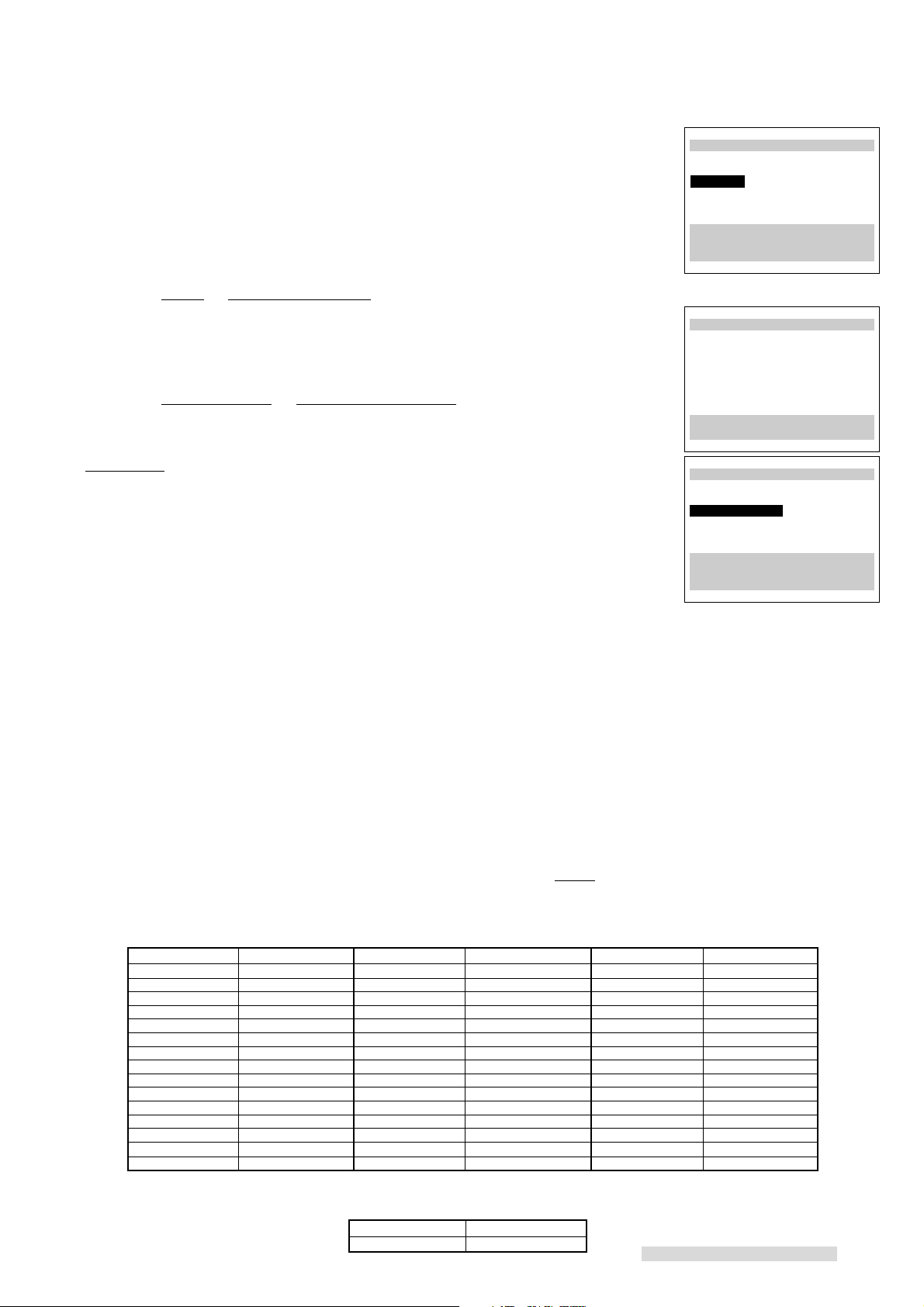
5 Brand code will be highlighted. Turn the ADJUST dial or press the number
buttons to select the manufacturer’s code number for your cable box or digital
cable box. The codes are listed below.
6 To determine if the brand code is correct, press CHANNEL on the remote. The
channel number on the front panel display should change. Then your cable
box or digital cable box should change to the exact same number a moment
after it appears on your VCR.
If your cable box or digital cable box does not change channels at all, or does not
show the exact same number, try the next brand code, if another is listed for your
type of cable box or digital cable box. Also make sure the IR emitter bulb faces the
IR window on the cable box.
If no code number is listed for your cable box, or if none of the listed numbers work,
try each code from 1 to 94. (For digital cable box, code numbers 3 to 5 are not
functional.)
If your cable box or digital cable box cannot be operated by a remote control (if it
has a mechanical dial or slide), then your VCR will not be able to change channels
on the cable box.
If your cable box will not respond to any of the codes, your VCR cannot change
channels on the cable box. You will need to change channels yourself, using the
cable box’s remote control. You should re-program your VCR, choosing Cable in
step 4. When programming to record, you will need to leave your cable box ON
and tuned to the channel you wish to record.
Manufacturer Code Number Manufacturer Code Number Manufacturer Code Number
ABC
Archer
Century
Citizen
Diamond
Eagle
Eastern
G C Electronic
Gemini
General Electric
General Instrument
Hamlin
Hitachi
Jerrold
Macom
Cable Box Brand Code
1, 2, 11
29, 58, 65
29, 65
29, 65
54, 58
17, 18, 19, 61, 62, 63
68
29, 65
5, 60
35
1,2,3,4,5,41,42,43,44,69,91
22, 23, 45, 46, 47
24
1,2,3,4,5,41,42,43,44,69,91
28
Magnavox
Movietime
NSC
OAK
Panasonic
Paragon
Pioneer
Philips
RCA
Realistic
Regal
Regency
Rembrandt
Samsung
Scientific Atlanta
Digital Cable Box Brand Code
GI
59, 61, 67
30, 31, 51, 54
20, 51, 52
27, 39, 40, 49, 50, 61
14, 21, 25
6, 7
14, 15, 16, 92, 93, 94
26, 61, 62, 63, 64
14, 21, 25
37, 38
45, 48
68
55, 56
5, 14, 21, 25, 29
10, 11, 12, 13
Manufacturer Code Number
1, 2
Sheritech
SL Marx
Sprucer
Stargate
Sylvania
Teknika
Texscan
Tocom
Toshiba
Unika
United Cable
Universal
Videoway
Viewstar
Zenith
∆AllSet
Please enter code from
your Owner's Guide:
ƒBrand code --
ππππππππππππππππππππππππ
Use ADJUST to select,
and ENTER.
Press MENU to go back.
57
5, 14, 29
14, 21, 25
5, 14, 29, 65
66
36
53, 66
1,2,3,4,5,41,42,43,44,69,91
32, 33, 34
48
2
30, 31, 54, 65
6, 7
17, 18, 19, 61, 62, 63
6, 7, 8, 9
17
Page 20
Setting Up Your VCR
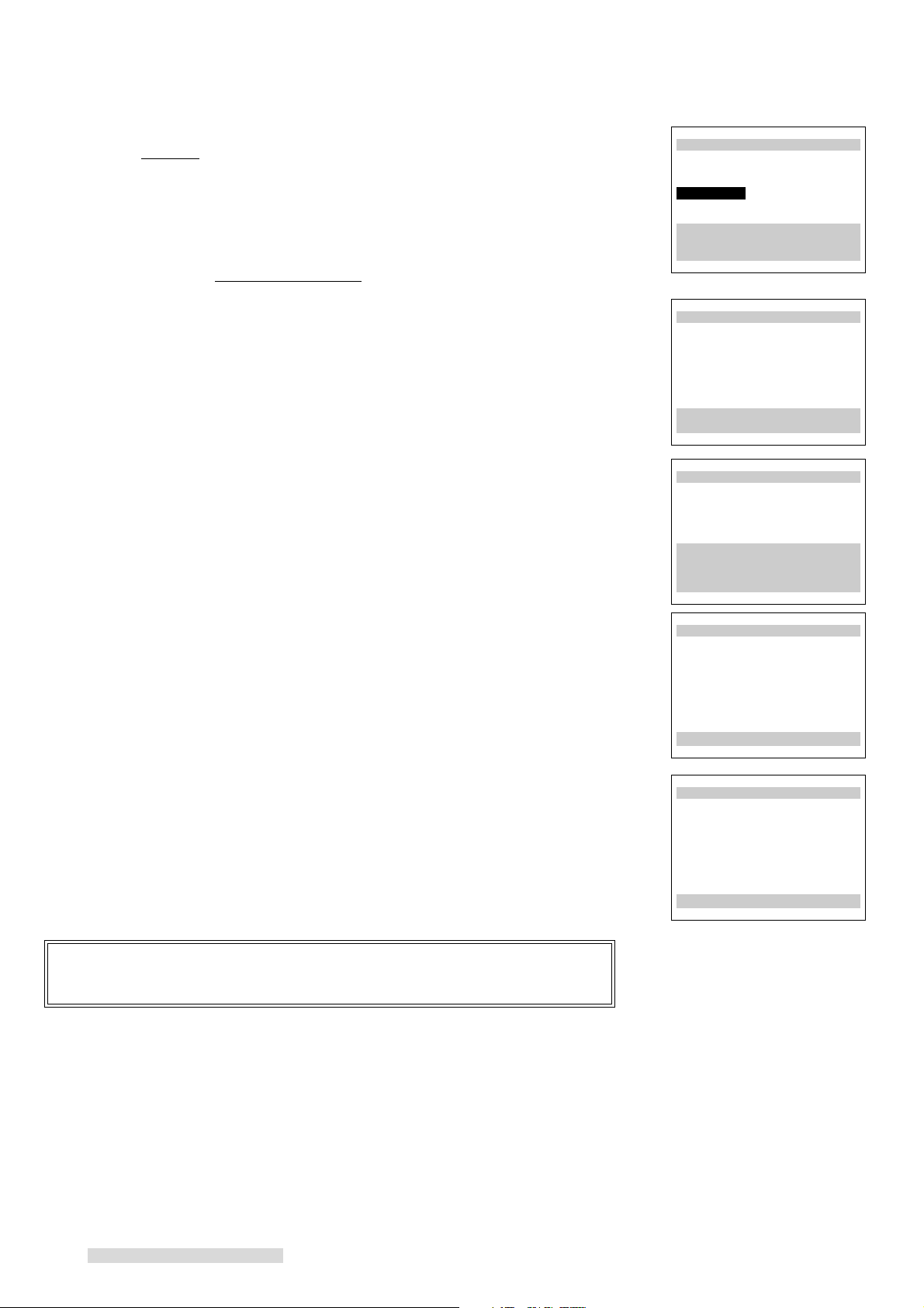
7 When the brand code is correct, turn the shuttle ring to the right. The screen
will add a Channel selection.
8 Use the ADJUST dial to select the channel on which your cable box or digital
cable box sends a signal to the VCR (normally channel 3 or 4). If you
connected your cable box or digital cable box with audio/video cables, use
INPUT to select L1 (if you used the rear panel jacks), or L2 (if you used the
front panel jacks). You cannot use both digital cable box and satellite receiver.
Thus if you selected Digital cable box only in step 4, you cannot select L2.
9 After entering the channel number, turn the SHUTTLE ring to the right. The
VCR will begin memorizing the available channels. During this process your
TV screen, the front panel display, and your cable box or digital cable box
should all display each channel number one by one.
10 When the VCR is finished memorizing, you will see the screen for entering your
zip code. Use the number keys to enter your zip code. For example, if your
zip code is 92618, press 9-2-6-1-8.
If you enter a number incorrectly, turn the SHUTTLE ring to the left or press
CANCEL.
When you have finished entering the zip code, turn the SHUTTLE ring to the
right.
∆AllSet
Your cable box sends a
signal on which channel?
ƒBrand code 1
ƒChannel 3
ππππππππππππππππππππππππ
Use ADJUST to select,
and ENTER.
Press MENU to go back.
∆AllSet
Now memorizing all the
stations you can receive
Channel 3
Stand by this may take
a few minutes
To cancel memorization,
press CANCEL
∆AllSet
Use number keys to enter
ZipCode
92618
Press ENTER when done.
Press CANCEL to erase
the ZipCode.
Press MENU to go back.
The VCR will begin to search for a channel that carries a time signal to set the
clock. If the VCR can find the channel, it will set the clock. You can see if the clock
has been set on the front panel display of your VCR.
The clock setting set up time varies, it may take up to 30 minutes as the VCR
searches one by one for a channel that carries a time signal.
If the VCR will not set the clock (the current time display still shows – –:– –), see
Setting the Clock on page 23.
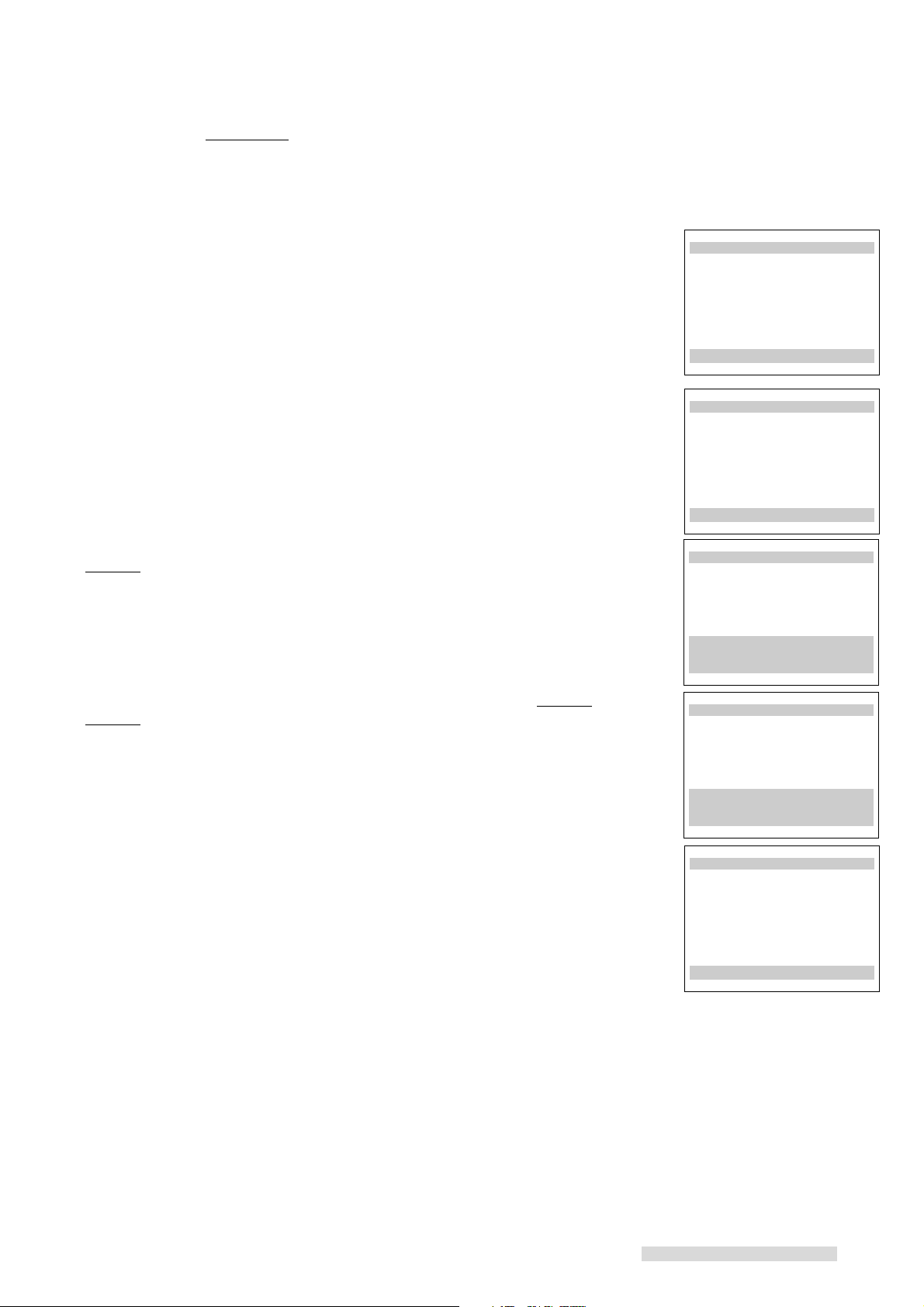
11 Once the VCR has set the clock, it shows the message indicating that the first
step is completed. Then, press POWER to turn off the VCR and leave the
VCR off for the night. The full set-up will be completed overnight (from about
Midnight to 7:00AM).
During this time, the VCR will search for a channel that carries data to set the
VCR Plus+ guide channel numbers for your area and then check the guide
channel number against the channel number you receive in your home and
select the correct lineup automatically.
IMPORTANT
If you use a cable box or digital cable box, you will need to leave your cable
box or digital cable box ON at all times.
∆AllSet
1st Step in Progress...
Please Wait.
Press MENU to go back.
∆AllSet
1st Step successful.
Please leave
your VCR Off Overnight
AllSet will be
completed Overnight
Press MENU to go back.
18
Page 21
Setting Up Your VCR
12 Turn on the VCR the next day. When you set your TV’s input to view the VCR
picture, you will see one of the following messages:
– Setup Completed
– Press MENU to see the message of AllSet
– Setup failed
Setup Completed means ALLSET has successfully completed the setup procedure
and set the VCR Plus+ system for recording. Press MENU to clear the screen.
Press MENU to see the message of AllSet means that you need to perform one
more operation before ALLSET can complete the setup procedure. Press MENU to
see the full message as shown here.
This message is displayed when there is more than one cable company servicing
your zip code area. In these situations, there will be more than one channel lineup
and your VCR may not be able to identify which is the correct lineup for your home.
To select the correct channel lineup:
1 Turn the SHUTTLE ring to the right. You will see the first lineup screen,
Lineup1, which will show selected key stations.
• Guide column shows the selected stations’ call letters or network name.
• VCRCH column shows the channel numbers used for the selected stations
by one of the local cable companies.
Note: As the VCR’s memory is limited, the Guide column may not display
call letters completely.
∆AllSet
Setup Completed.
Press MENU to exit
∆AllSet
Setup has not been
completed yet.
Please make a selection
to complete Setup.
Press ENTER to continue.
∆AllSet
Lineup1
Guide VCRCH Guide VCRCH
NBC π 023 --- π ---
HB0 π 027 --- π ---
--- π --- --- π ---
--- π --- --- π ---
Use ADJUST to choose
correct Lineup,
and ENTER.
2 Turn the ADJUST dial to cycle through the other possible lineups, Lineup2,
Lineup3 and so forth, until you find the lineup that matches your cable
company.
3 Turn the SHUTTLE ring to the right. The screen will instruct you to turn the
VCR off so that ALLSET can complete the setup overnight. Leave the VCR
turned off overnight and check it the next morning for the Setup Completed
display.
If the correct lineup is not displayed or you see Setup failed, the VCR cannot set
up the VCR␣ Plus+ guide channel numbers automatically. Set them manually when
you program your VCR to record with VCR Plus+ system. (See page 42.)
Setup failed means an error has prevented ALLSET from properly setting up the
VCR Plus+ guide channel numbers. This is normally caused by one of the following reasons:
• You entered an invalid zip code for your area. Turn the SHUTTLE ring to the
right to return to the zip code screen and re-enter the correct zip code. Try
the setup again and do not turn on the VCR until after 7:00 am the next day.
• You entered a new zip code that ALLSET is not ready to use. Turn the shuttle
ring to the right to return to the zip code screen and re-enter your old zip
code. Try the setup again and do not turn on the VCR until after 7:00 am the
next day.
• You turned on the VCR and interrupted the ALLSET procedure before it was
completed. ALLSET completes the setup normally between midnight and
7:00 am. Try the setup again and do not turn on the VCR until after 7:00 am
the next day.
•ALLSET information is not broadcast in your area. You will need to set the
VCR Plus+ Guide channel manually when you program your VCR to record
with VCR Plus+ system.
∆AllSet
Lineup2
Guide VCRCH Guide VCRCH
NBC π 032 --- π ---
HBO π 005 --- π ---
--- π --- --- π ---
--- π --- --- π ---
Use ADJUST to choose
correct Lineup,
and ENTER.
∆AllSet
Setup failed.
Press ENTER to try again
Press MENU to go back.
19
Page 22
Setting Up Your VCR
IMPORTANT
Automatic channel programming using ALLSET may include vacant channels
if there are stray signals or noise on those channels. If this occurs, you can
manually delete the channels using the procedure in the section Adding and
Deleting Channels.
You do not need to perform this set-up again unless your cable company
changes their channel lineup, or you move the VCR to a new address.
After a power failure, if you have set Clock set within the Set the clock menu
to AUTO, then ALLSET will automatically set the clock again.
Once the VCR has completed the ALLSET set-up, it can automatically set the
clock, including your time zone and daylight saving time. In order for the
auto clock function to work, the Clock set within the Set the clock menu must
be set to AUTO. Follow ALL the steps in Setting the Auto Clock.
Satellite Receiver Control
If you are using a satellite receiver, you can set up your VCR to change channels
on the satellite receiver.
1 Make sure you are viewing the picture coming from your VCR. Press MENU
on the remote control. VCR Main Menu appears.
2 Turn the ADJUST dial on the remote control to select First Time Set-Up. Turn
the SHUTTLE ring to the right.
3 You will see the First Time Set-Up menu. Turn the ADJUST dial to select Sat.
receiver.
IMPORTANT
You cannot select Sat. receiver if you select Digital Cable box only in step 4
of ALLSET (on page 17).
4 Turn the SHUTTLE ring to the right to select the correct code for your satellite
receiver.
Manufacturer Code
GE 1
RCA 1, 8
PRIMESTAR
®
2
Sony 3
DISH Network 4
Toshiba 5
Panasonic 6
Mitsubishi/Hughes 7
none OFF
5 After you have selected, press MENU twice to exit the menus.
IMPORTANT
After you have connected the satellite receiver and set the brand code, you
need to see if your VCR can control your satellite receiver. To do this, use
CHANNEL or number buttons on the VCR remote to tune to a satellite
channel. If the satellite channels appear on your TV, then your VCR can
control your satellite receiver.
ƒFirst Time Set-Up
∆AllSet
≈Set the clock
«Add/delete channels
±Sat.receiver (OFF)
ππππππππππππππππππππππππ
Use ADJUST to select,
and ENTER to change.
Press MENU to go back.
20
Page 23
Setting Up Your VCR
Adding and Deleting Channels
If necessary, you can manually add or delete channels after you have completed
the automatic channel memorizing by using ALLSET. You cannot do this for chan-
nels coming from a satellite receiver.
1 Make sure that video mute is ON. See page 60.
2 Set the VCR’s input to tuner. To do this, press INPUT on the remote control
until a channel number appears on the screen or the front panel display.
3 Press MENU on the remote control. VCR Main Menu appears.
4 Turn the ADJUST dial on the remote control to select First Time Set-Up. Turn
the SHUTTLE ring to the right.
5 You will see the First Time Set-Up menu. Turn the ADJUST dial to select Add/
delete channels. Turn the SHUTTLE ring to the right.
IMPORTANT
If you are recording, playing back a tape, receiving a video signal from an
external input, or watching a satellite receiver channel, then Not available will
flash on-screen. To correct this, stop the tape or turn off the menus and
switch the VCR’s input to tuner.
6 You will see the screen for adding or deleting channels. Use the ADJUST dial
to select the channel that you want to add or delete. Press ENTER or turn the
SHUTTLE ring to the right to add the channel; press CANCEL or turn the
SHUTTLE ring to the left to delete it.
7 When you are finished adding or deleting channels, press MENU three times to
exit the menus.
IMPORTANT
If you use ALLSET to memorize channels again, you will lose all of the
manual changes you made. All of the channels you deleted will be added; all
of the channels you added will be deleted. If your cable box receives only
one or two digit channels, you cannot add a three-digit channel.
ƒFirst Time Set-Up
∆AllSet
≈Set the clock
«Add/delete channels
±Sat.receiver (OFF)
ππππππππππππππππππππππππ
Use ADJUST to select,
and ENTER.
Press MENU to go back.
«Add/delete channels
Channel 39
Not in memory
Use ADJUST to select
a channel. Use ENTER
to add it, CANCEL to
delete it.
Press MENU to go back.
21
Page 24

Setting Up Your VCR
Selecting a Channel
Now that you have memorized channels, and added or deleted some, you will want
to be able to select channels. If you have not yet memorized channels using
ALLSET, see page 16. (If you selected digital cable box, you cannot select any
satellite channels.)
Antenna/Cable selections Your VCR can receive
indoor/outdoor antenna VHF/UHF channels 2–69
cable antenna without box cable channels 1–125
cable box only cable box channels 0–99
digital cable box digital cable box channels 0–999
Satellite Receiver selections Your VCR can receive
Mitsubish, Sony, RCA, GE, any channel from 100-999 provided
Toshiba, Panasonic, Hughes, by your satellite service
DISH Network
™
(cable channels 100-125 cannot be selected)
Satellite Receiver selections Your VCR can receive
PRIMESTAR
If you try to select a channel number that the VCR cannot receive, the VCR will not
change channels.
selecting antenna, cable or digital cable channels sequentially
Press CHANNEL on the remote control or turn the jog dial on the VCR front panel.
This will cycle through the channels in sequential numerical order.
When you select digital cable channels from 100 to 999, holding down the CHANNEL on the remote or turning the jog dial on the front panel quickly will advance the
channels in 10 channel increments.
selecting antenna, cable or digital cable channels directly
Use the number buttons on the remote control. For example, to choose channel
23, press 2-3. If you select digital cable channels, you can select the three digits
channels directly by using the number buttons. For example, to choose digital
cable channel 157, press the 1-5-7.
To select a single digit channel, such as channel 5; press 0-5. You can also press
5, then press ENTER.
selecting satellite channels sequentially
®
any channel from 1-999 provided
by your satellite service
(cable channels 100-125 cannot be selected)
Press CHANNEL on the remote or turn the jog dial on the VCR front panel. When
pressing the up arrow or turning the jog dial to the right, the lowest satellite channel
will follow the highest antenna or cable channel. When pressing the down arrow or
turning the jog dial to the left, the highest satellite channel will follow the lowest
antenna or cable channel. The other satellite channels will follow in numerical
order. Continuously holding down CHANNEL on the remote or turning the jog dial
on the front panel quickly will advance the channels in 10 channel increments.
selecting satellite channels directly
For Mitsubishi, Sony, RCA, GE, Toshiba, Panasonic, Hughes and DISH Network;
press the number buttons on the remote. For example, to go to channel 263, press
2-6-3.
For PRIMESTAR channels, press INPUT until the channel number with the
PRIMESTAR light ( ) appears on the front panel display. Then press the number buttons on the remote.
For one or two digit channel numbers, press the number buttons, then turn the
SHUTTLE ring to the right. For example, to go to channel 29, press 2-9-ENTER.
22
Page 25

Setting Up Your VCR
Setting the Clock
If your clock is set correctly, skip this section.
If your VCR cannot set the clock automatically in the ALLSET procedure, you have
to set the clock using either Setting the Auto Clock or Setting the Clock Manu-
ally.
Setting the Auto Clock
Your VCR can set the clock automatically by picking up a time signal which some
TV and cable channels transmit with their broadcasts. Most PBS stations send this
signal; however, this function works only if a channel in your area is broadcasting a
time signal. If you don’t receive this signal, set the clock manually.
1 Press MENU on the remote control. VCR Main Menu will appear.
2 Turn the ADJUST dial to select First Time Set-Up. Turn the SHUTTLE ring to
the right. The First Time Set-Up menu will appear. Use the ADJUST dial to
select Set the clock. Turn the SHUTTLE ring to the right.
3 You will see the Set the clock menu. Clock set will be highlighted. Turn the
ADJUST dial to select AUTO.
4 Turn the VCR off to activate the auto clock setting function.
The VCR will search for a channel that carries a time signal, then set your time
zone and daylight saving time. If there are only a few channels in your area that
carry time signals, it may take about 30 minutes to complete. If you turn the VCR
on before the correct time displays, the auto clock setting will be cancelled. See if
the clock has been set on the front panel display on the VCR.
If the VCR displays the wrong time, the time zone setting may not be correct. To
adjust this, follow the steps in If the VCR displays the wrong time. (See the next
page.)
IMPORTANT
When you memorized channels, if you chose Cable box only or Digital
cable box only, make sure you leave the cable box or digital cable box on.
At 3:00 am, when the VCR power is off, the VCR will begin to automatically
change channels on the cable box, one by one, to set the clock. At this time
you cannot use the cable box.
ƒFirst Time Set-Up
∆AllSet
≈Set the clock
«Add/delete channels
±Sat.receiver (OFF)
ππππππππππππππππππππππππ
Use ADJUST to select,
and ENTER.
Press MENU to go back.
≈Set the clock
ƒClock set (AUTO)
ππππππππππππππππππππππππŁ
Use ADJUST to select,
and ENTER.
Press MENU to go back.
If you want to use the cable box at 3:00 am, turn on the VCR or set the Clock
set of the Set the clock menu to MANUAL. In both cases, auto clock function
will be cancelled.
When you memorized channels, if you chose Cable or Indoor/outdoor ant.,
the VCR will set the clock as soon as you turn off the VCR, and at 3:00 am.
After a power failure, the VCR will automatically set the clock again. (If you
have set the Clock set setting of the Set the clock menu to MANUAL, the
auto clock function will not work.)
23
Page 26

Setting Up Your VCR
If the VCR displays the wrong time
1 Follow the procedure on the previous page to step 3. Then turn the SHUTTLE
ring to the right.
2 You will see the Set the clock menu. Channel will be highlighted. If you know
the channel that carries a time signal, turn the ADJUST dial to enter the
channel. Most PBS stations broadcast a time signal. For the quickest
response, enter your local PBS station. If you don’t know it, leave the channel
setting at AUTO. Turn the SHUTTLE ring to the right.
3 Time zone will be highlighted. Turn the ADJUST dial to select the time zone of
your area. Available time zones are: Atlantic, Eastern, Central, Mountain,
Pacific, Alaska, and Hawaii. Turn the SHUTTLE ring to the right.
4 Daylight savings will be highlighted. Turn the ADJUST dial to select AUTO, ON
or OFF. If you follow daylight saving time, select ON. If not, select OFF. If you
select AUTO, the VCR automatically sets the daylight saving time.
5 To activate the auto clock function, turn off the VCR.
Setting the Clock Manually
≈Set the clock
ƒChannel (065)
ƒTime zone (AUTO)
ƒDaylight savings(AUTO)
To activate Auto Clock,
turn off the VCR.Ł
ππππππππππππππππππππππππ
Use ADJUST to select,
and ENTER.
Press MENU to go back.
≈Set the clock
ƒChannel (065)
ƒTime zone (Eastern )
ƒDaylight savings(AUTO)
To activate Auto Clock,
turn off the VCR.Ł
ππππππππππππππππππππππππ
Use ADJUST to select,
and ENTER.
Press MENU to go back.
≈Set the clock
ƒChannel (065)
ƒTime zone (Eastern )
ƒDaylight savings(AUTO)
To activate Auto Clock,
turn off the VCR.Ł
ππππππππππππππππππππππππ
Use ADJUST to select,
and ENTER.
Press MENU to go back.
Skip this section if your VCR has set the clock correctly using ALLSET or the auto
clock function.
1 Press MENU on the remote control. You will see the VCR Main Menu.
2 Turn the ADJUST dial to select First Time Set-Up. Turn the SHUTTLE ring to
the right. First Time Set-Up menu will appear. Turn the ADJUST dial to select
Set the clock. Turn the SHUTTLE ring to the right.
3 You will see the Set the clock menu. Clock set will be highlighted. Turn the
ADJUST dial to select MANUAL. Turn the SHUTTLE ring to the right.
4 Daylight savings will be highlighted. Turn the ADJUST dial to select ON or
OFF. If you are currently following daylight savings, select ON. Otherwise,
select OFF. Turn the SHUTTLE ring to the right.
≈Set the clock
ƒClock set (MANUAL)
ππππππππππππππππππππππππŁ
Use ADJUST to select,
and ENTER.
Press MENU to go back.
≈Set the clock
ƒDaylight savings (OFF)
ƒMonth --
ƒYear --
ƒDate --
ƒTime --:--Ł
ππππππππππππππππππππππππŁ
Use ADJUST to select,
and ENTER.
Press MENU to go back.
24
Page 27

Setting Up Your VCR
5 Turn the ADJUST dial until the correct month appears on screen. Turn the
SHUTTLE ring to the right.
6 Turn the ADJUST dial to set the current year. Turn the SHUTTLE ring to the
right.
7 Turn the ADJUST dial to set the date. Turn the SHUTTLE ring to the right.
8 The hour numbers and the am/pm indicator will be blinking. Turn the ADJUST
dial to set the hour and am/pm at the same time. Turning the dial right moves
the clock forward; turning the dial left moves the clock backward. Turn the
SHUTTLE ring to the right.
9 Turn the ADJUST dial to set the minutes. When you have set the correct time,
turn the SHUTTLE ring to the right. First Time Set-Up menu will appear, and
the clock will start running.
≈Set the clock
ƒDaylight savings (OFF)
ƒMonth March
ƒYear 2001
ƒDate 1 Thursday
ƒTime 12:00pmŁ
ππππππππππππππππππππππππ
Use ADJUST to select,
and ENTER.
Press MENU to go back.
≈Set the clock
ƒDaylight savings (OFF)
ƒMonth March
ƒYear 2001
ƒDate 18 Sunday
ƒTime 12:00pm
ππππππππππππππππππππππππ
Use ADJUST to select,
and ENTER.
Press MENU to go back.
≈Set the clock
ƒDaylight savings (OFF)
ƒMonth March
ƒYear 2001
ƒDate 18 Sunday
ƒTime 7:00pmŁ
ππππππππππππππππππππππππ
Use ADJUST to select,
and ENTER.
Press MENU to go back.
10 Press MENU twice to turn off the menus.
You can adjust the daylight saving time manually. When Daylight savings is
highlighted, turn the ADJUST dial to select ON or OFF.
If you select ON, the VCR will set the clock forward one hour.
If you select OFF, the VCR will set the clock back one hour.
IMPORTANT
Any time you adjust this setting, check your programmed recordings to be
sure they are set to the correct times.
25
Page 28

Recording
Your new VCR offers a wide variety of recording options that take full advantage of
our advanced electronics. First, you can learn how to record a current broadcast.
Then, in another section of this book called Timer Recording, you can learn how
to program your VCR to record at a later time and day.
Recording a Current Digital Broadcast
Recording a Current Digital Broadcast in D-VHS Format
1 Follow the steps 1 to 4 of Setting Up Your VCR to Playback/Recording the
Digital Broadcast in D-VHS Format on page 12.
2 Select the channel you would like to record on the integrated HDTV or the
IEEE 1394-equipped HDTV receiver, not on the VCR.
3 Load a D-VHS tape with its erasure prevention tab intact into the VCR.
4 Make sure that the D-VHS button on the front panel is lit. If not, press this
button until it lights up.
5 When you are connecting the integrated HDTV or the IEEE 1394-equipped
HDTV receiver which is capable of controlling the VCR:
Operate your TV or receiver to record, to pause recording or to stop recording.
Refer to the TV or receiver owner’s guide for this procedure. During your TV or
receiver is operating the HS-HD2000U, d will be displayed on the front panel
display.
When you are connecting the integrated HDTV or the IEEE 1394-equipped
HDTV receiver which is not capable of controlling the VCR:
Press IEEE 1394 INPUT on the VCR remote control to select the device you
would like to record from. d1 to d5 will appear on the front panel display.
Select the number that corresponds to the device from which you would like to
record. And then press REC on the remote control or on the front panel.
Recording will start. When the VCR reaches the end of the tape, it will automatically rewind to the beginning of the tape and stop.
• You can stop recording at any time by pressing STOP or PAUSE on the remote
or on the front panel.
• To resume recording from STOP, press REC.
• To resume recording from PAUSE, press PAUSE.
You cannot use REC/˙REC LENGTH on the front panel to resume recording
from PAUSE.
IEEE 1394
INPUT
REC
D-VHS
PAUSE
STOP
REC
2 REC LENGTH
STOP
PAUSE
IMPORTANT
Refer to your integrated HDTV or IEEE 1394-equipped HDTV receiver
owner’s guide.
The recording mode will be changed automatically depending on the
broadcasting signal.
While the VCR is recording a digital broadcast, please do not change the
channel on the integrated HDTV or the IEEE 1394-equipped HDTV receiver.
If you pause the VCR for more than five minutes, recording will stop
automatically to protect the tape.
If you pause a recording, a mosaic noise, a still or a black picture may
appear when playing where the recording is resumed.
If you attempt to record on a tape that has had its erasure prevention tab
removed, the VCR will eject it. To record over such a tape, simply place a
piece of vinyl tape over the opening.
26
Erasure prevention tab
Page 29

Recording
REC
INPUT
STOP
STOP
PAUSE
PAUSE
SP/EP
REC
2 REC LENGTH
SP/EP
recording copy protected digital programs
Some programs have copy protect data to prohibit or restrict recording.
• Programs without copy protection : D-VHS recording is available.
• Programs with copy restriction : You can record in D-VHS format once, but
cannot copy.
• Programs prohibited from copying: D-VHS recording is not available.
When you record the program prohibited from copying or copy the program with
copy restriction, Error CP will appear on the front panel display.
Error CP will also appear when recording without receiving broadcasting signal. If
this occurs, check the hook up.
Recording a Current Digital Broadcast in Analog (S-VHS/S-VHS ET/
VHS) Format
1 Select the channel you would like to record on the integrated HDTV or the
IEEE 1394-equipped HDTV receiver, not on the VCR.
2 Load a tape with its erasure prevention tab intact into the VCR.
3 Set the recording format. See Selecting Recording Format on page 32.
4 Select the Front S-input in the S-VHS Set-UP menu when you connect an
integrated HDTV or an IEEE 1394-equipped HDTV receiver to the front panel
of the VCR, or Rear S-input when you connect the integrated HDTV or the
IEEE 1394-equipped HDTV receiver to the rear of the VCR. See Selecting S-
input Setting on page 33.
5 Press INPUT to select the external input to the position which is connected to
the integrated HDTV or the IEEE 1394-equipped HDTV receiver.
• select L1 if you connect to the rear panel.
• select L2 if you connect to the front panel.
6 Select the speed at which you would like to record by pressing SP/EP on the
remote control or on the front panel.
7 Press REC on the remote or REC/˙REC LENGTH on the front panel.
Recording will start. When the VCR reaches the end of the tape, it will automatically rewind to the beginning of the tape and stop.
• You can stop recording at any time by pressing STOP or PAUSE on the remote
or on the front panel.
• To resume recording from STOP, press REC.
• To resume recording from PAUSE, press PAUSE.
You cannot use REC/˙REC LENGTH on the front panel to resume recording
from PAUSE.
IMPORTANT
Be sure to connect the VCR and an integrated HDTV or an IEEE 1394equipped HDTV receiver with an S-video/video and an audio cable to record
a digital broadcast in analog format.
While the VCR is recording a digital broadcast, please do not change the
channel on the integrated HDTV or the IEEE 1394-equipped HDTV receiver.
The menu or the program list of an integrated HDTV or an IEEE 1394equipped HDTV will be recorded if it is displayed during recording.
If you pause the VCR for more than five minutes, recording will stop
automatically to protect the tape.
If you record a digital broadcast in analog format, the picture quality will not
be as clear as that of the original digital broadcast.
If you record a copy protected digital program, the copy protect data will also
be recorded.
27
Page 30

CHANNEL
JOG/CHANNEL
SP/EP
REC
INPUT
STOP
PAUSE
SP/EP
STOP
PAUSE
REC
2 REC LENGTH
Recording
Recording a Current Broadcast in Analog (SVHS/S-VHS ET/VHS) Format
1 Load a tape with its erasure prevention tab intact into the VCR.
2 Select the recording format. See Selecting Recording Format on page 32.
3 Select the speed at which you would like to record by pressing SP/EP on the
remote control or on the front panel.
4 Set the VCR’s input to tuner by pressing INPUT until a channel number is
shown on-screen or on the front panel display. If L1 or L2 appears instead of a
channel number, continue to press INPUT until a channel number appears. To
record channels from a PRIMESTAR® receiver, press INPUT until a channel
number with the PRIMESTAR light ( ) appears on the front panel display.
5 Select the channel you wish to record by pressing CHANNEL or the number
buttons on the remote or the jog dial on the front panel. If you are using a
cable box that the VCR cannot control, select channel 3 or 4 on the VCR, and
change the channel on the cable box, not on the VCR.
6 Press REC on the remote or REC/˙REC LENGTH on the front panel.
Recording will start. When the VCR reaches the end of the tape, it will automatically rewind to the beginning of the tape and stop.
• You can stop recording at any time by pressing STOP or PAUSE on the remote
or on the front panel.
• To resume recording from STOP, press REC.
• To resume recording from PAUSE, press PAUSE.
You cannot use REC/˙REC LENGTH on the front panel to resume recording
from PAUSE.
IMPORTANT
If you pause the VCR for more than five minutes, recording will stop
automatically to protect the tape.
If you record in extended play (EP), you will only be able to play the tape on
a VCR equipped for EP play, such as this one.
28
Page 31

INPUT
SP/EP
CHANNEL
JOG/CHANNEL
SP/EP
REC
2 REC LENGTH
2 REC LENGTH
Recording
Using One-Touch Recording (OTR)
One-Touch Recording (OTR) is a way to begin recording immediately, and have
your VCR stop recording and turn off automatically after your show is over.
1 When you record a digital broadcast in D-VHS format, follow the steps 1 to 4
on page 26.
When you record a digital broadcast in S-VHS/S-VHS ET/VHS format, follow
the steps 1 to 6 on page 27.
When you record an analog broadcast in S-VHS/S-VHS ET/VHS format, follow
the steps 1 to 5 on page 28.
2 Press REC/˙REC LENGTH on the front panel twice. The first time you press
the button, recording will begin. The second press of the same button adds 30
minutes to the OTR timer, displayed on the front panel. The OTR 2/˙REC
LENGTH on the remote control can also be used. When you first press this
button, the VCR will begin recording and 30 minutes is added to the OTR timer.
3 Press REC/˙REC LENGTH or OTR 2/˙REC LENGTH for each additional 30
minutes you want to add to the OTR timer, up to 4 hours. If you press REC/
˙REC LENGTH 10 times or OTR 2/˙REC LENGTH 9 times, you will see
End on the front panel display. The VCR will record until the end of the tape. If
you press REC/˙REC LENGTH an eleventh time, the VCR will resume
normal manual recording. If you press OTR 2/˙REC LENGTH a tenth time,
0:00 will be displayed on the front panel display and the recording will stop.
The OTR timer will begin to count down backwards. When it reaches zero, the
VCR will stop recording and turn off. The OTR light on the front panel display will
light up during the OTR recording.
If you program too much time into the OTR timer
Continue pressing REC/˙REC LENGTH or OTR 2/˙REC LENGTH. After the
End point you can start over from zero, adding time in 30 minute intervals.
How OTR affects other controls
If you press PAUSE during OTR, the VCR will pause recording, but the OTR timer
continues to count down.
Press PAUSE again to resume recording from the record-pause mode. The REC/
˙REC LENGTH will not resume your recording.
If you press STOP during OTR, you erase the OTR programming.
29
Page 32

INPUT
SP/EP
CHANNEL
JOG/CHANNEL
SP/EP
REC
2 REC LENGTH
1 START TIME
PAUSE
2 REC LENGTH
1 START TIME
Recording
PM
SP
CH
OTR2
PROG REC
Using Standby One-Touch Recording (OTR2)
Standby One-Touch Recording (also called OTR2) is a programming method to
begin recording within the next 24 hours and record in 30 minutes intervals. Before
you use OTR2, make sure the clock has been set correctly.
1 Load a tape with its erasure prevention tab intact into the VCR.
2 Select the recording format. See Selecting Recording Format on page 32.
3 Select the speed at which you would like to record by pressing SP/EP on the
remote control or on the front panel.
4 Set the VCR’s input to tuner by pressing INPUT until a channel number is
shown on-screen or on the front panel display. If L1 or L2 appears instead of a
channel number, continue to press INPUT until a channel number appears. To
record channels from a PRIMESTAR® receiver, press INPUT until a channel
number with the PRIMESTAR light ( ) appears on the front panel display.
5 Press CHANNEL or the number buttons on the remote or the front panel jog
dial to choose the channel to be recorded. If you are using a cable box that the
VCR does not control, select channel 3 or 4 on the VCR, and change the
channel on the cable box.
6 Press PAUSE/%START TIME on the front panel or OTR 2/%START TIME on
the remote to set the time when you wish recording to start (within 24 hours).
The start time is displayed on the front panel. The first time display is the next
half-hour increment from the current time. For example, if it is currently 2:15,
2:30 (next half-hour increment) will be displayed. Similarly, if it is currently
2:40, 3:00 (again, the next half-hour increment) will be displayed. Each time
you press the button, the start time is delayed by 30 minutes.
7 Press REC/˙REC LENGTH or OTR 2/˙REC LENGTH on the remote for
each additional 30 minutes you want to add to the OTR2 timer, up to 4 hours. If
you see End on the front panel display, the VCR will record until the end of the
tape.
If you have a cable box, a digital cable box, a PRIMESTAR® or a DISH
NetworkTM satellite receiver, leave the cable box or receiver turned ON. If the
HS-HD2000U does not control your cable box, leave the box tuned to the
station you wish to record.
After 30 seconds, the power will turn off and the programmed recording light will be
lit. The VCR will automatically turn on at the OTR2 start time and recording will
begin. When the OTR2 timer reaches zero, the VCR will stop recording and turn off
automatically. If the end of the tape is reached before OTR2 is finished, the VCR
will stop and the power will turn off.
IMPORTANT
Other programs you have set to record may be erased if:
• the start times are before the OTR2 start time
• conflicts with the OTR
2
• starts within one minute or less after the OTR2 finishes
If you turn the power on while your VCR is in stand-by for the OTR2, the
OTR2 programming will be erased.
To cancel OTR
2
• Turn the power OFF while you are programming the timer.
• Turn the power ON if you have finished programming the timer.
How OTR2 affects other controls
If you press REC/˙REC LENGTH on the front panel during OTR2 recording, 30
minutes will be added to the OTR2 timer. If you press STOP during OTR2 recording, you erase the OTR2 programming.
30
Page 33

Recording
Notes about Available Tape and Recording Time
Recording Format
The available recording format is as follows:
Recording format
D-VHS
S-VHS
S-VHS ET
VHS
When you use a D-VHS tape for D-VHS recording, the recording format is preset to
D-VHS format.
When recording in analog, the recording format is preset to S-VHS format when
you use a D-VHS or S-VHS tape, VHS format when you use a VHS tape.
D-VHS
Yes No No
Yes Yes No
Yes Yes Yes
Tape
S-VHS
VHS
YesNo No
Recording Mode
The available recording mode is as follows:
Recording format
D-VHS
S-VHS/S-VHS ET/VHS
HS (high speed) : You can record the half duration of STD.
STD (standard) : You can record the same duration as described on the tape.
SP (standard play) : You can record the same duration as described on the tape.
EP (extended play): You can record the duration as three times as described on
the tape.
HS
Yes Yes
STD
Analog recording modeDigital recording mode
SP EP
YesYes
When you record a digital broadcast in D-VHS format, the recording mode will be
changed automatically depending on the broadcast signal of the recorded program.
For analog recording, set the recording mode manually by pressing SP/EP.
When playing a tape, the VCR will automatically select the recording mode.
Recording Time
The available recording time is as follows:
D-VHS tape
Recording format
D-VHS
S-VHS/VHS
S-VHS/VHS tape
Recording format
S-VHS/S-VHS ET/VHS
Recording time (when recorded in STD/SP mode)
DF-240
4h 5h
2h 2h 30m
T-30
30m 1h
DF-300
T-60
DF-360
6h
3h
Recording time (when recorded in SP mode)
T-90
1h 30m 2h 2h 20m
DF-420 DF-480
7h
3h 30m8h4h
T-120 T-140
T-160 T-180
2h 40m 3h
T-200
3h 20m 3h 30m
T-210
31
Page 34

Recording
Using S-VHS Set-Up Menu
Selecting Recording Format
When recording in analog, the HS-HD2000U allows you to choose between
recording in standard VHS or Super VHS (S-VHS) when you use an S-VHS tape.
If you use a VHS tape, you can choose to record in S-VHS ET (Expansion Technology) mode or VHS. S-VHS ET mode allows you to record in S-VHS format on a
VHS tape. Though the picture quality of S-VHS ET mode will not be as clear as
that of the S-VHS format, you can record or playback with a higher picture quality
than VHS format.
1 Press MENU on the remote control. VCR Main Menu appears.
2 Turn the ADJUST dial on the remote control to select S-VHS Set-Up. Turn the
SHUTTLE ring to the right.
If you use S-VHS tape for recording:
3 Turn the ADJUST dial to select S-VHS record.
4 Turn the SHUTTLE ring to the right to select the recording format.
• select AUTO if you want to record in S-VHS.
• select OFF if you want to record in VHS.
5 Press MENU twice to exit the menus.
If you use VHS tape for recording:
3 Turn the ADJUST dial to select S-ET record.
4 Turn the SHUTTLE ring to the right to select the recording format.
• select OFF if you want to record in VHS.
• select ON if you want to record in S-VHS ET.
• AUTO will make the VCR automatically select VHS or S-VHS-ET as a result
of the PerfecTape® function. See page 61 for the PerfecTape®.
5 Press MENU twice to exit the menus.
ªVCR Main Menu
¬Program to record
ƒ1394 connection list
√Customize choices
»S-VHS Set-Up
ƒFirst Time Set-Up
Use ADJUST to select,
and ENTER.
Press MENU to exit menus
»S-VHS Set-Up
ƒS-VHS record (AUTO)
ƒS-ET record (OFF)
ƒFront S-input (OFF)
ƒRear S-input (OFF)
ƒRear S-through (OFF)
ππππππππππππππππππππππππ
Use ADJUST to select,
and ENTER to change.
Press MENU to go back.
»S-VHS Set-Up
ƒS-VHS record (OFF )
ƒS-ET record (ON )
ƒFront S-input (OFF)
ƒRear S-input (OFF)
ƒRear S-through (OFF)
ππππππππππππππππππππππππ
Use ADJUST to select,
and ENTER to change.
Press MENU to go back.
During playback, the VCR automatically selects the recorded format/mode.
• The S-VHS light on the front panel display will light up during the playback
with the tape recorded in S-VHS.
• The S-VHS ET light on the front panel display will light up during the
playback with the tape recorded in S-VHS ET.
IMPORTANT
For the best quality recording, use S-VHS tapes and record in the S-VHS
format.
The quality of S-VHS ET recordings will vary by the quality of VHS tapes
used. For the best quality S-VHS ET recordings, it is recommended that you
use HG (high grade) tapes.
S-VHS recordings can be played on:
• S-VHS VCRs
• VHS VCRs with S-VHS Quasi playback capabilities
S-VHS ET recording can be played on:
• S-VHS VCRs (not all S-VHS VCRs will be able to play S-VHS ET)
• VHS VCRs with S-VHS Quasi playback capabilities
Please use this VCR or S-VHS VCR with S-VHS ET mode to playback the
tape recorded in S-VHS ET for better picture quality.
32
Page 35

Recording
Selecting S-input Setting
To watch the picture from other equipment through the VCR, you have to select the
S-video input jack or video input jack that matches the equipment. If you connect
the satellite receiver to the VCR with an S-video cable, you have to set Rear Sinput to ON.
1 Press MENU on the remote control. VCR Main Menu appears.
2 Turn the ADJUST dial on the remote control to select S-VHS Set-Up. Turn the
SHUTTLE ring to the right.
ªVCR Main Menu
¬Program to record
ƒ1394 connection list
√Customize choices
»S-VHS Set-Up
ƒFirst Time Set-Up
Use ADJUST to select,
and ENTER.
Press MENU to exit menus
3 Turn the ADJUST dial to select Front S-input if you use the front panel jacks, or
select Rear S-input if you use the rear panel jacks.
4 Turn the SHUTTLE ring to the right to select which input jack to input.
• select OFF when you want to input signals from video input jack.
• select ON when you want to input signals from S-video input jack.
5 Press MENU twice to exit the menus.
Using S-through
This function allows you to view the video signal from the equipment connected to
the back of the VCR even when the VCR is off. To use this function, you have to
connect your VCR and TV, and also connect your VCR and the other equipment
with an S-Video cable. For example, if you connect satellite receiver with an SVideo cable, you can watch the satellite video signal on your TV with the VCR
power off when you set Rear S-through to ON.
1 Press MENU on the remote control. VCR Main Menu appears.
2 Turn the ADJUST dial on the remote control to select S-VHS Set-Up. Turn the
SHUTTLE ring to the right.
»S-VHS Set-Up
ƒS-VHS record (AUTO)
ƒS-ET record (OFF)
ƒFront S-input (ON )
ƒRear S-input (OFF)
ƒRear S-through (OFF)
ππππππππππππππππππππππππ
Use ADJUST to select,
and ENTER to change.
Press MENU to go back.
»S-VHS Set-Up
ƒS-VHS record (AUTO)
ƒS-ET record (OFF)
ƒFront S-input (OFF)
ƒRear S-input (ON )
ƒRear S-through (OFF)
ππππππππππππππππππππππππ
Use ADJUST to select,
and ENTER to change.
Press MENU to go back.
ªVCR Main Menu
¬Program to record
ƒ1394 connection list
√Customize choices
»S-VHS Set-Up
ƒFirst Time Set-Up
Use ADJUST to select,
and ENTER.
Press MENU to exit menus
3 Turn the ADJUST dial to select Rear S-through.
4 Turn the SHUTTLE ring to the right to set Rear S-through to ON or OFF.
5 Press MENU twice to exit the menus.
»S-VHS Set-Up
ƒS-VHS record (AUTO)
ƒS-ET record (OFF)
ƒFront S-input (OFF)
ƒRear S-input (OFF)
ƒRear S-through (ON )
ππππππππππππππππππππππππ
Use ADJUST to select,
and ENTER to change.
Press MENU to go back.
33
Page 36

Recording
Using Audio and Video Functions
The audio and video function menus allow you to set things such as listening to the
stereo track of your recording, or setting the tape length to have the remaining time
display function work properly. The VCR will display the functions and settings on
your TV screen. The first section describes the functions, the next section tells you
how to adjust the functions.
Audio functions Video functions
audio monitor 3D-Y/C DNR + TBC
normal record Tape (length) D-VHS Tape (length)
repeat playback PerfecTape Select
Search to blank PerfecTape
counter zero stop
Descriptions of Audio Functions
Audio monitor (Listen to):
This allows you to listen to the various audio tracks that your VCR is capable of
recording.
• Choose Stereo to listen to both stereo channels.
• Choose L to listen to the left channel of a stereo track.
• Choose R to listen to the right channel of a stereo track.
• Mono track is lower in quality than the others. The audio monitor is
automatically set to Mono if you are watching a tape that was not recorded in
VHS Hi-Fi. Set the audio monitor to Mono to hear SAP signal recorded on
the mono track of a Hi-Fi tape.
®
IMPORTANT
Surround Sound systems: If you have your VCR connected to a surround
sound system, set the audio monitor to Stereo. Surround sound requires
both left and right channels to create the rear channel effects.
When the VCR is not playing a tape, you will see the following displays on the TV
screen for 3 seconds when you change the channel or press DISPLAY.
If you change the channel to: Display
stereo broadcast Stereo
SAP broadcast SAP
stereo and SAP Stereo+SAP
When the VCR is playing a tape, you will see the following displays on the TV
screen for 4 seconds when you press DISPLAY.
The audio monitor you listen to Display
Stereo Audio Stereo
L Audio L
R Audio R
Mono Audio Mono
Normal recording (Record):
When your VCR is recording, it actually records the audio portion of a program
twice: once on the stereo Hi-Fi tracks, and once on the mono track. Additionally,
your VCR can receive Separate Audio Program (SAP) broadcasts. A SAP broadcast is an alternative soundtrack for a program; it is often a sound track in another
language. The SAP broadcast is recorded only on the mono track.
Use the normal recording function to record the SAP broadcast on the mono track
by choosing Stereo+SAP. Otherwise, choose Stereo. In either case, the main
program is recorded on the stereo Hi-Fi track. Also, if there is no SAP broadcast,
the VCR will record the main program on the mono track.
34
Page 37

Recording
Descriptions of Video Functions
3D-Y/C
This function improves the picture quality when you watch or record a TV program
or picture coming through your other equipment. You can set this function also by
using the DNR&TBC on the front panel. (See the next page.) Set it to ON when
you want to use this feature, If not, set it to OFF.
DNR + TBC (Digital Noise Reduction + Time Base Correction)
This adjusts the picture when playing a tape. If you set it to ON, the video noise,
vibration or distortion in the picture will be reduced. You can set this function also
by using the DNR&TBC on the front panel. (See the next page.) Set it to ON when
you want to use this feature. If not, set it to OFF. It will take a few seconds to
adjust the picture. It will not work during playback of special effects. When using
this setting, colors may possibly appear different than normal.
Tape (Tape)
Adjust this function to ensure the accuracy of the Remaining Time display. The
remaining time function does not work properly with a tape that is less than 30
minutes long.
Length of tape Use setting
2 hours long or less
(T-30 through T-120) T-120
160 minutes (T-160) T-160
180 minutes (T-180) T-180
200 minutes (T-200) T-200
210 minutes (T-210) T-210
D-VHS Tape (D-VHS Tape)
Adjust this function to ensure the accuracy of the Remaining Time display.
Length of tape Use setting
DF-160 through DF-300 DF-300
DF-360 DF-360
DF-420 DF-420
DF-480 DF-480
PerfecTape Select (Play PerfecTape)
This function turns on the PerfecTape Select circuitry, which automatically maximizes picture quality when playing a worn or poor quality tape.
Set the switch to Soft to soften the picture, set it to Sharp to sharpen it. Set it to
Normal when you do not want to use this feature. Use Normal on new or high
quality tapes. If it is set to Auto, the VCR will automatically select the ideal setting
of PerfecTape Select depending on the condition of the tape.
Counter zero stop (Counter zero stop)
This function is used to automatically fast forward or rewind to “0H00M00S” and
stop the tape. See page 58 for more information on this feature.
Repeat playback (Repeat play)
Use this function to repeatedly play a section of tape between two index marks.
See page 59 for more information on this feature.
Search to blank (Search to blank)
Use this function to search the beginning of the blank section of the tape. See
page 59 for more information on this feature.
PerfecTape® (PerfecTape)
PerfecTape function allows you to test the quality of video tapes you will record on.
After each test, the VCR adjusts its circuitry in order to make the best possible
recording on your tape. See page 61 for more information on this feature.
35
Page 38

Recording
Selecting and Adjusting the Audio and Video Functions
1 If you set your remote control to be able to operate Mitsubishi televisions by
code button 1, make sure that the VCR/TV slide switch is set to VCR position.
See Using the Remote Control to Operate your TV on page 64.
2 Press VIDEO repeatedly until the function you want to adjust appears.
audio and video function menu
VCR
Listen to: Stereo
Use ADJUST to select
3 Turn the ADJUST dial on the remote to adjust the setting. The functions will
disappear if you do not press any buttons for 5 seconds.
When you set your remote control to be able to operate Mitsubishi televisions by
code button 1:
The TV audio function will appear when you press TV AUDIO on the HS-HD2000U
remote.
The TV video function will appear when you press VIDEO on the HS-HD2000U
remote with the VCR/TV slide switch is set to TV position.
setting 3D-Y/C or DNR + TBC by using DNR&TBC on the front panel
1 When you want to set 3D-Y/C, press DNR&TBC on the front panel during the
tape is stopped.
When you want to set DNR + TBC, press DNR&TBC on the front panel during
the tape is playing.
TV AUDIO
VIDEO
2 ADJUST
DNR&TBC
When 3D-Y/C or DNR + TBC is in operation, DNR&TBC button will be lit. If
not, the button will be turned off.
IMPORTANT
The audio and video function menus do not appear:
• when the VCR menu is displayed
• during special effects playback
Tape, D-VHS Tape and 3D-Y/C function does not appear during playback.
Play PerfecTape and DNR + TBC is displayed only during playback.
PerfecTape displays only when a tape, with its erasure tab intact, is loaded
and the VCR is stopped.
36
Page 39

Timer Recording
Mitsubishi offers 6 ways to set your VCR to record upcoming broadcasts. Choose
from:
D-VHS Timer Recording
Analog Timer Recording of Digital Broadcast
VCR Plus+ system programming (easy)
On LCD programming
Conventional VCR timer recording
Quick Program (easy) -- VCR does not need to be on to begin programming
You can schedule up to 8 recording events within a one month period.
Clock must be set before any timer recordings can be performed.
D-VHS Timer Recording
To set the timer recording of the digital broadcast in D-VHS format, set the timer
recording on the integrated HDTV or on the IEEE 1394-equipped HDTV receiver,
not on the VCR. Refer to your TV or receiver owner’s guide.
1 Follow the steps 1 to 4 of Setting Up Your VCR to Playback/Recording the
Digital Broadcast in D-VHS format on page 12.
2 Load a D-VHS tape with its erasure prevention tab intact into the VCR.
3 Make sure that the D-VHS button on the front panel is lit. If not, press this
button until it lights up.
4 Press POWER on the VCR front panel or on the remote control to turn off the
VCR.
5 Set the timer recording on the integrated HDTV or on the IEEE 1394-equipped
HDTV receiver. Refer to your TV or receiver owner’s guide for this procedure.
The integrated HDTV or the IEEE 1394-equipped HDTV receiver will receive the
program to be recorded on the start time you have set and send the signal to start
recording to the VCR. The VCR will start recording automatically. The integrated
HDTV or the IEEE 1394-equipped HDTV receiver will send the signal to stop
recording to the VCR on the end time you have set, and the VCR will stop recording automatically.
IMPORTANT
The recording mode will be changed automatically depending on the
broadcasting signal.
Depending on your integrated HDTV or IEEE 1394-equipped HDTV receiver,
the programmed D-VHS recording may not be recorded if you turn on the
VCR while it is in stand-by mode for the D-VHS timer recording.
The programmed D-VHS timer recording may not be recorded correctly
depending on your integrated HDTV or IEEE 1394-equipped HDTV receiver.
When you connect more than one integrated HDTVs or IEEE 1394-equipped
HDTV receivers, the D-VHS timer recording of only one integrated HDTV or
IEEE 1394-equipped HDTV receiver will be activated. In this case, while the
VCR is in stand-by mode for the D-VHS timer recording, press INPUT on the
VCR remote to set the VCR’s input to the tuner or press IEEE 1394 INPUT to
select d1 to d5 which corresponds to the receiver or the TV from which you
would like to record.
37
Page 40

Timer Recording
When you program both the D-VHS and analog timer recording
When you turn the VCR off, the programmed recording light will appear on the front
panel display, showing that the VCR is in stand-by mode for the analog timer
recording. In this mode, the D-VHS timer recording you have set may not be
recorded depending on the integrated HDTV or IEEE 1394-equipped HDTV
receiver that you are using. (Refer to your TV or receiver owner’s guide for the
details.) If so, you need to press POWER on the VCR front panel once to cancel
the stand-by mode when the D-VHS timer recording is activated. When you press
POWER, the programmed recording light will be turned off but the VCR power will
remain off. Please note that the VCR cannot activate the analog timer recording
while the programmed recording light is turned off.
When the D-VHS timer recording is over, press POWER on the front panel twice to
turn on the programmed recording light.
Analog (S-VHS/S-VHS ET/VHS) Timer Recording
of Digital Broadcast
IMPORTANT
Be sure to connect the VCR and an integrated HDTV or an IEEE 1394equipped HDTV receiver with an S-video/video and an audio cable to record a
digital broadcast in analog format.
1 Select the Front S-input in the S-VHS Set-UP menu when you connect an
integrated HDTV or IEEE 1394-equipped HDTV receiver to the front panel of the
VCR, or Rear S-input when you connect an integrated HDTV or IEEE 1394equipped HDTV receiver to the rear of the VCR. See Selecting S-input
Setting on page 33.
2 Select the channel you would like to record on an integrated HDTV or an IEEE
1394-equipped HDTV receiver, not on the VCR.
3 Load a tape with its erasure prevention tab intact into the VCR.
4 Press MENU. VCR Main Menu appears on your screen. Turn the ADJUST
dial to select Program to record. Turn the SHUTTLE ring to the right.
If there is at least one programmed recording already entered, you will see the
Recap screen. Wait 4 seconds, and the VCR Plus+ system menu will appear.
IMPORTANT
If you have already programmed 8 recording events, Program memory is full
will appear on your screen for 3 seconds, and then the Recap screen will
appear. Use CANCEL to erase an entry before you can add another one.
5 VCR Plus+ system menu appears. See page 42 to learn how to program with
VCR Plus+ system. To pass this screen, turn the SHUTTLE ring to the right.
ªVCR Main Menu
¬Program to record
ƒ1394 connection list
√Customize choices
»S-VHS Set-Up
ƒFirst Time Set-Up
Use ADJUST to select,
and ENTER.
Press MENU to exit menus
¬Program to record
CH DAY ON OFF
10 TH15 9:00a10:30pSP
§--- -- --:-- --:-- SP
--- -- --:-- --:-- SP
--- -- --:-- --:-- SP
ππππππππππππππππππππππππ
Use ADJUST to select,
and ENTER.
Press MENU to go back.
Recap screen
¬VCR Plus+ system
Use number keys to enter
the PlusCode number
--------
or press ENTER to
program.
Press MENU to go back.
38
Page 41

Timer Recording
6 Program to record menu appears. Turn the ADJUST dial to choose the
channel you would like to record. Turn the SHUTTLE ring to the right.
• Select External L1 if you connect an integrated HDTV or an IEEE 1394-
equipped HDTV receiver to the rear panel.
• Select External L2 if you connect an integrated HDTV or an IEEE 1394-
equipped HDTV receiver to the front panel.
7 Day will flash. Turn the ADJUST dial to choose the day on which you want to
record; for example, Monday the 12th.
Your choices are:
• a single day up to one month away.
• every day from Monday through Friday; for example, to tape a soap opera.
To program, turn the ADJUST dial until Monday-Friday appears.
• the same day every week; for example, to tape your favorite weekly sitcom.
To program, turn the ADJUST dial until Every and the desired day of the
week appears.
Turn the SHUTTLE ring to the right once you have made your choice.
8 The hour numbers of the start time will flash. Turn the ADJUST dial to set the
hour when recording is to start. Turn the SHUTTLE ring to the right.
9 The minute numbers of the start time will flash. Turn the ADJUST dial to set
the minutes when recording is to start. Turn the SHUTTLE ring to the right.
10 Set the stop time the same way as the start time, using steps 8 and 9.
¬Program to record
ƒChannel External L1
ƒDay --
ƒStart time --:--
ƒStop time --:--
ƒRecord speed AUTO
ππππππππππππππππππππππππ
Use ADJUST to select,
and ENTER.
Press MENU to go back.
¬Program to record
ƒChannel External L1
ƒDay Monday 12
ƒStart time --:--
ƒStop time --:--
ƒRecord speed AUTO
ππππππππππππππππππππππππ
Use ADJUST to select,
and ENTER.
Press MENU to go back.
¬Program to record
ƒChannel External L1
ƒDay Monday 12
ƒStart time 11:00am
ƒStop time --:--
ƒRecord speed AUTO
ππππππππππππππππππππππππ
Use ADJUST to select,
and ENTER.
Press MENU to go back.
11 Turn the ADJUST dial to set the recording speed:
SP = standard play; EP = extended play; AUTO = auto. Auto speed
programming is discussed on page 48. Turn the SHUTTLE ring to the right.
IMPORTANT
If you turn the SHUTTLE ring to the right when you set the timer recording
incompletely, Program is not completed will appear on your screen.
If two programmed recording times overlap, VCR is already programmed for
that time will display on your screen for about 3 seconds, and then the Recap
screen will appear. The program you have just set will flash for 3 seconds
and the start time and the stop time will be shown in red letters. The start
and stop time of the overlapped program will be highlighted in red color. You
will need to erase one of them.
12 The programmed memory will appear on the Recap screen.
13 To program additional recording times, select an empty program line by turning
ADJUST dial. Turn the SHUTTLE ring to the right. The VCR Plus+ system
menu will appear. Continue the programming procedure from step 5.
14 When you are finished with all programming, check the following:
• Leave an integrated HDTV or an IEEE 1394-equipped HDTV receiver turned ON.
• Turn the VCR power OFF and make sure the programmed recording light is lit.
IMPORTANT
While the VCR is recording a digital broadcast, please do not change the
channel on an integrated HDTV or an IEEE 1394-equipped HDTV receiver.
¬Program to record
ƒChannel External L1
ƒDay Monday 12
ƒStart time 11:30am
ƒStop time 1:30pm
ƒRecord speed SP
ππππππππππππππππππππππππ
Use ADJUST to select,
and ENTER.
Press MENU to go back.
Recap screen
¬Program to record
CH DAY ON OFF
10 TH15 9:00p10:30pSP
§ L1 MO12 11:30a 1:30pSP
--- -- --:-- --:-- SP
--- -- --:-- --:-- SP
ππππππππππππππππππππππππ
Use ADJUST to select,
and ENTER.
Press MENU to go back.
The menu or the program list of an integrated HDTV or an IEEE 1394equipped HDTV will be recorded if it is displayed during recording.
If you record a digital broadcast in analog format, the picture quality will not
be as clear as that of the original digital broadcast.
If you record a copy protected digital program, the copy protect data will also
be recorded.
39
Page 42

Timer Recording
Conventional VCR Timer Recording
1 Load a tape with its erasure prevention tab intact into the VCR.
2 Press MENU. VCR Main Menu appears on your screen. Turn the ADJUST
dial to select Program to record. Turn the SHUTTLE ring to the right.
If there is at least one programmed recording already entered, you will see the
Recap screen. Wait 4 seconds, and the VCR Plus+ system menu will appear.
IMPORTANT
If you have already programmed 8 recording events, Program memory is full
will appear on your screen for 3 seconds, and then the Recap screen will
appear. Use CANCEL to erase an entry before you can add another one.
3 VCR Plus+ system menu appears. See page 42 to learn how to program with
VCR Plus+ system. To pass this screen, turn the SHUTTLE ring to the right.
ªVCR Main Menu
¬Program to record
ƒ1394 connection list
√Customize choices
»S-VHS Set-Up
ƒFirst Time Set-Up
Use ADJUST to select,
and ENTER.
Press MENU to exit menus
¬Program to record
CH DAY ON OFF
10 TH15 9:00a10:30pSP
§--- -- --:-- --:-- SP
--- -- --:-- --:-- SP
--- -- --:-- --:-- SP
ππππππππππππππππππππππππ
Use ADJUST to select,
and ENTER.
Press MENU to go back.
Recap screen
¬VCR Plus+ system
Use number keys to enter
the PlusCode number
--------
or press ENTER to
program.
Press MENU to go back.
4 Program to record menu appears. Turn the ADJUST dial to choose the
channel you would like to record; for example, channel 2. Turn the SHUTTLE
ring to the right.
• If you are using a cable box that the VCR cannot control, enter the channel
number on which the cable box sends a signal to your VCR (usually channel
3 or 4).
• If you are recording from a DSS®, PRIMESTAR® or DISH Network™ satellite
receiver, simply choose the channel you would like to record; for example,
channel 245. SAT will display next to the channel number.
• To record from an external source, press INPUT or turn the ADJUST dial to:
Select External L1 for a source connected to the rear panel.
Select External L2 for a source connected to the front panel.
5 Day will flash. Turn the ADJUST dial to choose the day on which you want to
record; for example, Monday the 12th.
Your choices are:
• a single day up to one month away.
• every day from Monday through Friday; for example, to tape a soap opera.
To program, turn the ADJUST dial until Monday-Friday appears.
• the same day every week; for example, to tape your favorite weekly sitcom.
To program, turn the ADJUST dial until Every and the desired day of the
week appears.
Turn the SHUTTLE ring to the right once you have made your choice.
6 The hour numbers of the start time will flash. Turn the ADJUST dial to set the
hour when recording is to start. Turn the SHUTTLE ring to the right.
7 The minute numbers of the start time will flash. Turn the ADJUST dial to set
the minutes when recording is to start. Turn the SHUTTLE ring to the right.
8 Set the stop time the same way as the start time, using steps 6 and 7.
¬Program to record
ƒChannel 2
ƒDay --
ƒStart time --:--
ƒStop time --:--
ƒRecord speed AUTO
ππππππππππππππππππππππππ
Use ADJUST to select,
and ENTER.
Press MENU to go back.
¬Program to record
ƒChannel 2
ƒDay Monday 12
ƒStart time --:--
ƒStop time --:--
ƒRecord speed AUTO
ππππππππππππππππππππππππ
Use ADJUST to select,
and ENTER.
Press MENU to go back.
¬Program to record
ƒChannel 2
ƒDay Monday 12
ƒStart time 11:00am
ƒStop time --:--
ƒRecord speed AUTO
ππππππππππππππππππππππππ
Use ADJUST to select,
and ENTER.
Press MENU to go back.
40
Page 43

forward
shuttle ring
ADJUST
backward
POWER
STOP
STOP
Timer Recording
9 Turn the ADJUST dial to set the recording speed:
SP = standard play; EP = extended play; AUTO = auto. Auto speed
programming is discussed on page 48. Turn the SHUTTLE ring to the right.
IMPORTANT
If you turn the SHUTTLE ring to the right when you set the timer recording
incompletely, Program is not completed will appear on your screen.
If two programmed recording times overlap, VCR is already programmed for
that time will display on your screen for about 3 seconds, and then the Recap
screen will appear. The program you have just set will flash for 3 seconds
and the start time and the stop time will be shown in red letters. The start
and stop time of the overlapped program will be highlighted in red color. You
will need to erase one of them.
10 The programmed memory will appear on the Recap screen. “S” next to the
channel number indicates satellite channels.
11 To program additional recording times, select an empty program line by turning
ADJUST dial. Turn the SHUTTLE ring to the right. The VCR Plus+ system
menu will appear. Continue the programming procedure from step 3.
12 When you are finished entering the programs you wish to record, check the
following:
• If you have a cable box, a digital cable box, a PRIMESTAR® or a DISH
Network™ satellite receiver, leave the cable box or receiver turned ON.
• If your VCR does not control your cable box, leave the box tuned to the
station you wish to record.
• Turn the VCR power OFF and make sure the programmed recording light is
lit.
¬Program to record
ƒChannel 2
ƒDay Monday 12
ƒStart time 11:30am
ƒStop time 1:30pm
ƒRecord speed SP
ππππππππππππππππππππππππ
Use ADJUST to select,
and ENTER.
Press MENU to go back.
Recap screen
¬Program to record
CH DAY ON OFF
10 TH15 9:00p10:30pSP
§ 2 MO12 11:30a 1:30pSP
--- -- --:-- --:-- SP
--- -- --:-- --:-- SP
ππππππππππππππππππππππππ
Use ADJUST to select,
and ENTER.
Press MENU to go back.
IMPORTANT
When programmed recordings of 4 and under are entered, only 4 of the 8
program lines appear on the Recap screen at any one time. To see
additional program lines, turn the ADJUST dial to scroll the lines on the
screen.
Cancelling a Recording in Progress
There are two ways to cancel a recording in progress:
Press STOP. The recording stops, but the program is not cancelled. Therefore, if you press REC, the recording will start again.
Press POWER on the front panel. The recording stops and the program is
cancelled.
Changing while Programming
To change one of your settings (such as start time) while you are programming:
Turn the SHUTTLE ring to the right to move forward through the program list.
Turn the SHUTTLE ring to the left to move backward.
Then use ADJUST dial to change the setting.
Programming not cancelled
Programming cancelled
You will cancel the entire program if you turn the shuttle ring to the left while the
channel number is flashing.
41
Page 44

Timer Recording
¬VCR Plus+ system
PlusCode number:5678
ƒOnce
ƒDaily
ƒWeekly
Use ADJUST to select,
and ENTER.
Press MENU to go back.
VCR Plus+® System Programming
The VCR Plus+ system allows you to program your VCR to record by simply
entering a PlusCode programming number. You can find this number in TV Guide
or possibly your local TV listings. There are 2 ways of using VCR Plus+ System
Programming on the HS-HD2000U. You can use either of the 2 following sections,
VCR Plus+ System Programming Using the On Screen Display or VCR Plus+
System Programming Using the Remote Control LCD.
VCR Plus+ System Programming Using the On Screen Display
1 Load a tape with its erasure prevention tab intact into the VCR.
2 Press MENU. VCR Main Menu appears on your screen. Turn the ADJUST
dial to select Program to record. Turn the SHUTTLE ring to the right.
IMPORTANT
If the VCR memory is full, Program memory is full will appear for 3 seconds,
and then the Recap screen will appear. Use CANCEL to erase an entry
before you can add another one.
If there is at least one programmed recording already entered, the Recap
screen will appear. Wait 4 seconds, and the VCR Plus+ system menu will
appear.
3 VCR Plus+ system menu will appear. Use the number buttons on the remote
control to enter the PlusCode number for the television show you want to
record. For example, if the PlusCode number for the program you want to
record is 5678, simply enter 5-6-7-8. See your local newspaper or TV Guide
for PlusCode numbers.
4 If you enter a number incorrectly, turn the SHUTTLE ring to the left or press
CANCEL on the remote control. When you have finished entering the
PlusCode number, turn the SHUTTLE ring to the right.
IMPORTANT
If the code number you entered is wrong, The PlusCode number is not valid
will display on the screen for 3 seconds, and then the VCR Plus+ system
menu will reappear.
ªVCR Main Menu
¬Program to record
ƒ1394 connection list
√Customize choices
»S-VHS Set-Up
ƒFirst Time Set-Up
Use ADJUST to select,
and ENTER.
Press MENU to exit menus
¬VCR Plus+ system
Use number keys to enter
the PlusCode number
5678----
Press ENTER when done.
Press CANCEL to erase
the PlusCode number.
Press MENU to go back.
5 Use the ADJUST dial to select whether you want to record your program once,
daily, or weekly.
• Once will record a program one time.
• Daily will record the same channel at the same time, Monday through Friday.
• Weekly will record the same channel at the same time, on the same day
each week.
After you have made your choice, turn the SHUTTLE ring to the right.
IMPORTANT
If two programmed recording times overlap, VCR is already programmed for
that time will display on the screen. You will need to erase the previous
program before you can enter the new one.
6 Recap screen will appear. The program you have chosen to record will be
highlighted.
The channel number will appear in blue color. Make sure that the correct
channel number is shown on the screen. If the displayed number is not
correct, press INPUT to make the number flash, then turn the ADJUST dial to
correct the channel number. Press the ENTER to complete. “S” will appear
next to the channel number when you select a satellite channel.
42
Recap screen
¬Program to record
CH DAY ON OFF
§ 2 MO12 11:30a 1:30pSP
--- -- --:-- --:-- SP
--- -- --:-- --:-- SP
--- -- --:-- --:-- SP
ππππππππππππππππππππππππ
Press INPUT to correct
channel setting.
Press MENU to go back.
Page 45

POWER
Timer Recording
7 If you wish to change the record speed, turn the SHUTTLE ring to the right
repeatedly until the record speed is flashing. Change the recording speed by
turning the ADJUST dial. Turn the SHUTTLE ring to the right.
8 To program additional recording times, select an empty program line by turning
the ADJUST dial. Turn the SHUTTLE ring to the right. You will return to the
VCR Plus+ system menu. Continue the VCR Plus+ system programming
procedure from step 3.
9 When you are finished with all programming, check the following:
• If you have a cable box, a digital cable box, a PRIMESTAR® or a DISH
Network™ satellite receiver, leave the cable box or receiver turned ON.
• If your VCR does not control your cable box, leave the box tuned to the
station you wish to record.
• Turn the VCR power OFF and make sure the programmed recording light is
lit.
If you want to stop the programmed recording after it starts, press POWER on the
front panel.
VCR Plus+ System Programming Using the Remote Control LCD
1 Load a tape with its erasure prevention tab intact into the VCR.
2 Press VCR Plus+ on the remote control. PlusCode No. appears on the remote
control LCD.
¬Program to record
ƒChannel 2
ƒDay Monday 12
ƒStart time 11:30am
ƒStop time 1:30pm
ƒRecord speed SP
ππππππππππππππππππππππππ
Use ADJUST to select,
and ENTER.
Press MENU to go back.
PlusCode No.
VCR-A
3 Use the number buttons on the remote control to enter the PlusCode number
for the television show you want to record. For example, if the PlusCode
number for the program you want to record is 5678, simply enter 5-6-7-8. See
your local newspaper or TV Guide for PlusCode numbers.
If you enter a number incorrectly, press CANCEL or turn the SHUTTLE ring on
the remote control to the left.
4 Use DAILY/WEEKLY if you want to record your program daily or weekly. If you
want to record a program one time, skip this step.
• select DAILY if you want to record the same channel at the same time,
Monday through Friday.
• select WEEKLY if you want to record the same channel at the same time, on
the same day each week.
5 Press SP/EP under the flip cover of the remote control to select the recording
mode; for example, SP. SP = standard play; EP = extended play.
• select SP if you want to record in SP mode.
• select EP if you want to record in EP mode.
• do not make a selection if you want to keep the recording in the mode that
was previously used.
6 Press TRANSFER. The PlusCode number will be transferred to the VCR, and
the Recap screen will appear. The program you have chosen to record will be
highlighted.
Make sure that the programming contents shown on the screen is correct. The
channel number will appear in blue color. If the displayed number is not
correct, press INPUT to make the number flash, then turn the ADJUST dial to
correct the channel number. Press ENTER to complete.
TRANSFER
PlusCode No.
DAILY
PlusCode No.
DAILY
PlusCode No.
¬Program to record
CH DAY ON OFF
10 TH15 9:00p10:30pSP
§ 2 MO12 11:30a 1:30pSP
--- -- --:-- --:-- SP
--- -- --:-- --:-- SP
ππππππππππππππππππππππππ
Use ADJUST to select,
and ENTER.
Press MENU to go back.
VCR-A
TRANSFER
VCR-A
TRANSFER
SP
VCR-A
“S” will appear next to the channel number when you select a satellite channel.
IMPORTANT
If you cannot select the other program line by turning ADJUST dial on the
remote, press PAUSE first, and then turn the ADJUST dial.
43
Page 46

Timer Recording
IMPORTANT
You cannot transfer the PlusCode number while the VCR is recording or on
recording pause mode.
If the VCR memory is full, Program memory is full will appear for 8 seconds,
and then the Recap screen will appear. Use CANCEL to erase an entry
before you can add another one.
If the code number you entered is wrong, The PlusCode number is not valid
will display on the screen for 8 seconds, and then the VCR Plus+ system
menu will appear.
If two programmed recording times overlap, VCR is already programmed for
that time will display on the screen for 8 seconds. You will need to erase the
previous program before you can enter the new one.
If the remote control has failed to transfer the data, The transfer has failed.
Please transfer again will be displayed on the screen for 8 seconds. To
transfer the same PlusCode number again, press TRANSFER twice.
Pressing TRANSFER once displays the PlusCode number on the remote
control LCD again, and pressing it again transfers the displayed PlusCode
number.
7 To program additional recording times, follow the procedure from step 2 to 6
again.
8 When you are finished with all programming, check the following:
• If you have a cable box, a digital cable box, a PRIMESTAR® or a DISH
Network™ satellite receiver, leave the cable box or receiver turned ON.
• If your VCR does not control your cable box, leave the box tuned to the
station you wish to record.
• Turn the VCR power OFF and make sure the programmed recording light is
lit.
IMPORTANT
To cancel VCR Plus+ System Programming while programming with the
remote control LCD, press VCR Plus+.
To cancel VCR Plus+ System Programming while displaying the Recap
screen, press CANCEL to cancel the selected program, and then press
MENU to exit the Program to record.
44
Page 47

QUICK PROGRAM
Timer Recording
Quick Program
Quick Program is an exclusive Mitsubishi feature that simplifies the process of
programming your VCR to record. When you press QUICK PROGRAM on the
remote control, you will immediately see the VCR Plus+ system menu and can
begin programming right away.
You can use this feature even when the VCR is stopped, playing, fast forwarding,
rewinding, or off. (Quick program does not work while using OTR2.)
1 Press QUICK PROGRAM on the remote control. If the VCR is off, it will turn
on. After tuning your TV to the correct channel or input, VCR Plus+ system
menu will appear.
IMPORTANT
If the VCR memory is full, Program memory is full will appear for 3 seconds,
and then the Recap screen will appear. Use CANCEL to erase an entry
before you can add another one.
2 Complete steps 3 through 10 in Conventional VCR timer recording. (See
page 40.)
When you have finished, press QUICK PROGRAM again.
If the VCR is stopped, it will turn off and be ready to record your program at
a later time.
¬VCR Plus+ system
Use number keys to enter
the PlusCode number
--------
or press ENTER to
program.
Press MENU to go back.
Recap screen
If the VCR is playing, recording, fast forwarding or rewinding, the menus
will turn off, but the VCR power will remain on.
3 When you are finished with entering the programs you wish to record, check
the following:
• If you have a cable box, a digital cable box, a PRIMESTAR® or a DISH
Network™ satellite receiver, leave the cable box or receiver turned ON.
• If your VCR does not control your cable box, leave the box tuned to the
station you wish to record.
• Make sure the VCR is turned OFF and the programmed recording light is lit
before the recording time.
IMPORTANT
If you press QUICK PROGRAM, but the clock is not set, Set the clock menu
will appear. Set the clock manually.
¬Program to record
CH DAY ON OFF
§ 2WE14 11:30a 1:30pSP
10TH15 9:00p10:00pEP
7E-WE 8:00a 9:00aEP
S125FR16 5:30p 5:45pEP
8TU20 11:00p 0:30aSP
S980M-F 7:00p 7:15pEP
15SA 1 8:00p 9:00pEP
46SU18 7:00a 9:00aSP
45
Page 48

Timer Recording
VCR-A
DAYCH
ON OFF
VCR-A
DAYCH
ON OFF
VCR-A
DAYCH
ON OFF
am
VCR-A
DAYCH
ON OFF
am
pm
TRANSFER
SP
VCR-A
DAYCH
ON OFF
On LCD Programming
On LCD Programming is a programming method to set the timer recording on the
remote control LCD and transfer it to the VCR. For example, setting the timer
recording of the program on channel 2, on the 12th from 10:00 am to 11:00 am, in
SP mode:
1 Load a tape with its erasure prevention tab intact into the VCR.
2 Press LCD PROGRAM on the remote control. The display for programming
the timer recording will appear on the remote control LCD and CH will flash.
3 Turn the ADJUST dial to choose the channel you would like to record. Turn the
SHUTTLE ring to the right.
• If you are using a cable box that the VCR cannot control, enter the channel
number on which the cable box sends a signal to your VCR (usually channel
3 or 4).
• If you are recording from a DSS®, PRIMESTAR® or DISH Network™ satellite
receiver, simply choose the channel you would like to record; for example,
channel 245. S will display next to the channel number.
• To record from an external source, press INPUT or turn the ADJUST dial to:
Select L1 for a source connected to the rear panel.
Select L2 for a source connected to the front panel.
4 DAY will flash. Turn the ADJUST dial to choose the day on which you want to
record.
Your choices are:
• a single day up to one month away.
• every day from Monday through Friday; for example, to tape a soap opera.
To program, turn the ADJUST dial until DAILY appears.
• the same day every week; for example, to tape your favorite weekly sitcom.
To program, turn the ADJUST dial until E- (for EACH) and the desired day of
the week appears.
Turn the SHUTTLE ring to the right once you have made your choice.
5 The hour numbers of the start time will flash. Turn the ADJUST dial to set the
hour when recording is to start. Turn the SHUTTLE ring to the right.
6 The minute numbers of the start time will flash. Turn the ADJUST dial to set
the minutes when recording is to start. Turn the SHUTTLE ring to the right.
7 Set the stop time the same way as the start time, using steps 5 and 6.
8 Press SP/EP under the flip cover of the remote control to select the recording
mode.
• select SP if you want to record in SP mode.
• select EP if you want to record in EP mode.
• do not make a selection if you want to keep the recording in the mode that
was previously used.
9 Press TRANSFER. The programmed contents will be transferred to the VCR,
and Recap screen will appear. The program you have chosen to record will be
highlighted.
Make sure that the programming contents shown on the screen is correct.
IMPORTANT
If you cannot select the other program line by turning ADJUST dial on the
remote, press PAUSE first, and then turn the ADJUST dial.
46
¬Program to record
CH DAY ON OFF
10 TH15 9:00p10:30pSP
§ 2 MO12 11:30a 1:30pSP
--- -- --:-- --:-- SP
--- -- --:-- --:-- SP
ππππππππππππππππππππππππ
Use ADJUST to select,
and ENTER.
Press MENU to go back.
Page 49

Timer Recording
IMPORTANT
You cannot transfer the program while the VCR is recording or on recording
pause mode.
If you have already programmed 8 recording events, Program memory is full
will appear on your screen for 8 seconds, and then the Recap screen will
appear. Use CANCEL to erase an entry before you can add another one.
If two programmed recording times overlap, VCR is already programmed for
that time will display on your screen for about 8 seconds, and then the Recap
screen will appear. The program you have just set will flash for 3 seconds
and the start time and the stop time will be shown in red letters. The start
and stop time of the overlapped program will be highlighted in red color. You
will need to erase one of them.
If you set the impossible date, The date is wrong. Please re-enter the date.
will be displayed on the screen for 8 seconds.
If the remote control is failed to transfer, The transfer is failed. Please
transfer again will be displayed on the screen for 8 seconds. To transfer the
same programming contents again, press TRANSFER twice. Pressing
TRANSFER once displays the programming contents on the remote control
LCD again, and pressing it again transfers the displayed program.
10 To program additional recording times, follow the procedure from step 2 to 9
again.
11 When you are finished with all programming, check the following:
• If you have a cable box, a digital cable box, a PRIMESTAR® or a DISH
Network™ satellite receiver, leave the cable box or receiver turned ON.
• If your VCR does not control your cable box, leave the box tuned to the
station you wish to record.
• Turn the VCR power OFF and make sure the programmed recording light is lit.
IMPORTANT
To cancel programming while programming with the remote control LCD,
press LCD PROGRAM.
To cancel programming while displaying the Recap screen, press CANCEL
to cancel the selected program, and then press MENU to exit the Program to
record menu.
Timer Recording Hints
To use the VCR before timer recording begins, press POWER on the remote once.
This turns the programmed recording light off and the VCR on.
If you use POWER on the front panel for this purpose, press it twice. Pressing it
once turns off the programmed recording light; pressing it again turns the VCR on.
VCR POWER
When you are finished using the VCR, turn the VCR power off again. Make sure
the programmed recording light is back on.
After a program has been recorded, the VCR memory of that program is cleared
(unless you have scheduled the VCR to record the program every day or every
week).
If there is already a program in the VCR’s memory, you will see the Recap screen
when you bring up the menus for programming to record (unless you are programming with the QUICK PROGRAM). If the VCR’s memory is full, Program memory
is full will appear on the screen. If so, you must erase a program before you can
enter a new one.
POWER
REC
REC
47
Page 50

Timer Recording
If a tape runs out during timer recording, the VCR ejects the tape and the programmed recording light (
new tape and press REC. Recording will resume.
The programmed recording will be cancelled unless you turn the VCR off before
the recording starts. Do not use an integrated HDTV or an IEEE 1394-equipped
HDTV receiver to turn on or function the VCR while the VCR is in stand-by mode for
the timer recording.
) and the tape status symbol ( ) will flash. Load a
PROG REC
If you forget to load a tape, the programmed recording light (
) and the tape
PROG REC
status symbol ( ) will flash when you turn the VCR power off. (A tape without an
erasure tab will be ejected. To correct this, load a tape with its erasure tab intact,
and turn off the VCR.)
Do not overlap the recording times you enter into the VCR. If you set two analog
programmed recording times to overlap, VCR is already programmed for that time
will appear on your screen. When you set the analog and the D-VHS timer recording times overlap, these timer recordings may not be recorded correctly.
Remember that the VCR will record over the next section of tape. If you want to
save a tape, remove it and instead use a different tape for a new recording.
Your VCR will not record over a tape that has the erasure prevention tab removed.
All rental movies have this tab removed, so they are safe from being accidentally
erased.
Auto Speed Programming
Use auto speed programming if you want to record as much of the program as
possible in standard play (SP) speed, but you want the VCR to automatically switch
to extended play (EP) if there is not enough tape left.
Auto speed programming is only available for one program. In the first slot, the
recording speed default is AUTO.
Make sure that the Tape video function matches the length of tape you are using.
See Selecting and adjusting the audio and video functions on page 36.
At the point where the recording mode changes from standard play (SP) to extended play (EP), some noise may be in the picture or sound when playing the
tape.
Program Caution
If your VCR is set to record in analog format, but the power is still ON within 3
minutes before timer recording starts, this screen will appear to remind you to turn
off the VCR.
If the VCR is still turned on 12 seconds before the start time of the recording, that
timer recording will be cancelled.
program caution
REC in 3 min
Turn off VCR
48
Page 51

Timer Recording
POWER
PROG REC
PROG REC
TV Programs that End on the Day After
If you want to start the recording at 11:00 PM and end it at 2:00 AM the next day,
simply set the start time to 11:00 PM on the recording start day and the end time to
2:00 AM. There is no need to change the day of the week.
Program Skip Using Menus
Sometimes you may want to skip one day of a timer recording but do not want to
erase it. Program skip will prevent the recording, for that day only, of a program
you have scheduled to record every day or every week.
1 Press MENU on the remote control. Your VCR will turn on and VCR Main
Menu will appear. Turn the ADJUST dial to select Program to record. Turn the
SHUTTLE ring to the right.
2 Recap screen will display for 4 seconds. While this screen is displayed, turn
the ADJUST dial to place the cursor arrow next to the program you wish to
skip.
3 Press STOP. The cursor arrow will change to a X.
4 Press MENU twice to turn off the menus.
To resume recording every day or every week, change the X to the cursor arrow by
following steps 1 to 4 again.
Program Skip Using the POWER Button
If you have entered only one program into your VCR’s memory, you can skip the
program without going into the VCR’s menus. Simply press POWER on the front
panel once. The programmed recording light will turn off, and the program will be
skipped. If you decide not to skip the program, press POWER on the front panel
twice; the programmed recording light will light up again.
¬Program to record
CH DAY ON OFF
2 MO12 11:30a 1:30pSP
10 TH15 9:00p10:00pEP
§ 2 M-F 8:00a 8:30aSP
--- -- --:-- --:-- SP
ππππππππππππππππππππππππ
Use ADJUST to select,
and ENTER.
Use STOP to skip on/off
¬Program to record
CH DAY ON OFF
2 MO12 11:30a 1:30pSP
10 TH15 9:00p10:00pEP
X 2 M-F 8:00a 8:30aSP
--- -- --:-- --:-- SP
ππππππππππππππππππππππππ
Use ADJUST to select,
and ENTER.
Use STOP to skip on/off
Changing Timer Recording Settings
1 Press MENU on the remote control. Your VCR will turn on and VCR Main
Menu will appear. Turn the ADJUST dial to select Program to record. Turn the
SHUTTLE ring to the right.
2 Recap screen will display for 4 seconds. While this screen is displayed, turn
the ADJUST dial to place the cursor arrow next to the program you wish to
change. Turn the SHUTTLE ring to the right. You will see the Program to
record setting menu.
3 Turn the SHUTTLE ring to the right repeatedly to select the item you wish to
change. Turn the ADJUST dial to change it. Then Turn the SHUTTLE ring to
the right repeatedly to return the altered program to the Recap screen.
4 Press MENU twice to turn off the menus. Then press POWER to turn off the
VCR. Make sure the programmed recording light is on.
Recap screen
¬Program to record
CH DAY ON OFF
§ 2 MO12 11:30a 1:30pSP
--- -- --:-- --:-- SP
--- -- --:-- --:-- SP
--- -- --:-- --:-- SP
ππππππππππππππππππππππππ
Use ADJUST to select,
and ENTER.
Press MENU to go back.
¬Program to record
ƒChannel 2
ƒDay Monday 12
ƒStart time 11:30am
ƒStop time 1:30pm
ƒRecord speed EP
ππππππππππππππππππππππππ
Use ADJUST to select,
and ENTER.
Press MENU to go back.
49
Page 52

Timer Recording
TIMER RESET
VCR Rear Panel
TIMER RESET
Cancelling a Timer Recording before the Recording Starts
1 Press MENU on the remote control. Your VCR will turn on and VCR Main
Menu will appear on your screen. Turn the ADJUST dial on the remote control
to select Program to record. Turn the SHUTTLE ring to the right.
2 Recap screen will display for 4 seconds. While this screen is displayed, turn
the ADJUST dial to place the cursor next to the program you wish to cancel.
3 Press CANCEL. The program is erased.
4 Press MENU twice to turn off the menus.
Using a Satellite Receiver
If you are using a Mitsubishi, Panasonic, RCA, Sony, Toshiba, or Hughes satellite
receiver, your VCR will automatically turn the receiver on when a timer recording
begins and off when the recording ends.
However, if you are using a PRIMESTAR® or DISH Network™ receiver, you will have
to turn the receiver on before a timer recording begins.
Before turning off the VCR, to put your VCR in stand-by for recording, make sure
that your satellite receiver’s menu turns off.
You can watch satellite channels through your VCR even when the VCR is turned
off but only if you connected your VCR and TV with an S-Video cable and the Rear
S-through in the S-VHS Set-Up menu is set to ON. If you used a standard video
cable, you can only view satellite channels through your VCR when the VCR is on.
Recap screen
¬Program to record
CH DAY ON OFF
§ 2 MO12 11:30a 1:30pSP
--- -- --:-- --:-- SP
--- -- --:-- --:-- SP
--- -- --:-- --:-- SP
ππππππππππππππππππππππππ
Use ADJUST to select,
and ENTER.
Press MENU to go back.
TIMER RESET
You can use TIMER RESET on the rear panel to erase both the clock and all timer
recordings.
To use TIMER RESET, press it with a pencil or a ball point pen. The power will turn
off and the clock will be cleared. All timer recordings are erased.
If you have set the Clock set setting of the Set the clock menu to AUTO, the auto
clock function will automatically set the clock again.
Memory Backup
If the VCR is without power for 30 minutes or less, it will retain the clock and the
programmed settings. The VCR must have been plugged in for at least an hour
beforehand to charge this backup. If the power is lost for more than 30 minutes,
the time and the programmed settings will be lost.
If you have set the Clock set setting of the Set the clock menu to AUTO, the auto
clock function will automatically set the clock again when power is restored.
50
Page 53

Editing Features
Copying a Tape from D-VHS to D-VHS
When you connect a D-VHS VCR equipped with IEEE 1394 INTERFACE terminal to the HS-HD2000U with an IEEE
1394 cable, you can copy a tape from D-VHS format to D-VHS. You cannot edit the tape while copying from D-VHS to
D-VHS.
1 Connect an IEEE 1394 cable to IEEE 1394
INTERFACE on the playback VCR and to IEEE
1394 INTERFACE on the HS-HD2000U. You can
use either of the two IEEE 1394 INTERFACE
terminals.
IMPORTANT
Do not pull out an IEEE 1394 cable during
copying the tape.
You cannot copy a tape in D-VHS format from
digital video equipment (for example, digital
video camera) even if it is connected with an
IEEE 1394 cable.
2 Set the recording VCR to be able to control the
playback VCR.
To do this, when you use HS-HD2000U as a
recording VCR, press IEEE 1394 INPUT on the
remote control to display d1 to d5 on the front panel
which will correspond to the D-VHS VCR used as a
playback VCR. If you use this VCR as a playback
VCR and the other VCR as a recording VCR, refer
to the recording VCR owner’s guide for this
procedure.
3 Put a D-VHS tape with the erasure prevention tab
intact to the recording VCR.
4 When you are using the HS-HD2000U as a
recording VCR, make sure that the D-VHS button on
the front panel is lit. If it is not, press the button to
light it up.
5 Put the tape you want to copy into the playback VCR
and find the cue point. Press STOP if the picture
starts playing.
IMPORTANT
As it will take a few seconds to automatically
select the recording mode, stop the tape slightly
before the point you want to start copying.
6 On the playback VCR, press PLAY, then PAUSE.
7 On the recording VCR, press REC, then PAUSE.
8 Press the PAUSE buttons on both VCRs at the same
time to begin copying the tape.
9 When finished, press STOP on both VCRs.
IMPORTANT
The programs prohibited from copying or the
programs with copy restriction cannot be copied
correctly. When you use the HS-HD2000U as a
recording VCR and copy such programs, Error
CP appears on the front panel display.
HS-HD2000U ANOTHER D-VHS VCR
IEEE 1394
INTERFACE
IEEE 1394
INTERFACE
IEEE 1394
INTERFACE
51
Page 54

Editing Features
Copying a Tape from D-VHS to Analog
To copy a tape from D-VHS to analog format, use the HS-HD2000U as a playback VCR and connect to an integrated
HDTV or an IEEE 1394-equipped HDTV receiver with an IEEE 1394 cable. And then connect an integrated HDTV or an
IEEE 1394-equipped HDTV receiver to the recording VCR with an S-video/video and audio cable. The digital signal
which is played back on HS-HD2000U will be changed to analog signal by an integrated HDTV or an IEEE 1394equipped HDTV receiver, and this analog signal will be sent to the recording VCR to be recorded.
1 Connect an IEEE 1394 cable to IEEE 1394
INTERFACE on an integrated HDTV or an IEEE
1394-equipped HDTV receiver and to IEEE 1394
INTERFACE on the HS-HD2000U. You can use
either of the two IEEE 1394 INTERFACE terminals.
2 Connect the audio cable to AUDIO OUT L and R on
an integrated HDTV or an IEEE 1394-equipped HDTV
receiver and to AUDIO IN L and R on the recording
VCR.
3 If the recording VCR is S-VHS, connect an S-video
cable to S-VIDEO OUT on an integrated HDTV or an
IEEE 1394-equipped HDTV receiver and to the
recording VCR.
If the recording VCR is standard VHS, connect a
video cable to VIDEO OUT on an integrated HDTV or
an IEEE 1394-equipped HDTV receiver and to the
VIDEO IN on the recording VCR.
4 Select the external input of the recording VCR.
5 Put a blank tape into the recording VCR. If you want
to record in S-VHS, be sure to use an S-VHS tape.
6 Put the tape you want to copy into the HS-HD2000U
and find the cue point. Press STOP if the picture
starts playing.
7 On the recording VCR, press REC, then PAUSE.
8 On the HS-HD2000U, press PLAY, then PAUSE.
9 Press the PAUSE buttons on both VCRs at the
same time to begin copying the tape.
10 When finished, press STOP on both VCRs.
IMPORTANT
The picture quality of the copied program will not
be as clear as that of the original digital
broadcast.
Digital programs with copy restriction or
programs prohibited from copying cannot be
copied.
IEEE 1394-equipped
HDTV receiver
IEEE 1394
INTERFACE
IEEE 1394
INTERFACE
HS-HD2000U PLAYBACK
IEEE 1394
INTERFACE
OR
AUDIO OUT R
AUDIO OUT L
AUDIO IN L
AUDIO IN R
integrated HDTV
R
L
L
R
RECORDING VCR
S-VIDEO OUT
VIDEO OUT
Use either a video cable or
an S-video cable.
Do not use both.
VIDEO IN
S-VIDEO IN
52
Page 55

Editing Features
Copying a Tape from Analog to Analog
There are two basic ways to make a copy of a tape from analog to analog.
One way is to use the HS-HD2000U to record and another VCR for playback.
The other way is to use another VCR to record and use the HS-HD2000U for playback.
Regardless of which method you may choose, you will need one RCA audio cable and one S-video cable to connect the
two VCRs. You can use either a standard RCA video cable or an S-video cable. If you do not have these cables, they
are available at your local electronics dealer. The highest quality is achieved through an S-video cable.
Using the HS-HD2000U to Record from Another VCR
1 Connect the audio cable to AUDIO OUT L and R on
the playback VCR and to AUDIO IN L and R on the
HS-HD2000U. If the playback VCR is mono, use
only the AUDIO IN L on the HS-HD2000U.
2 If the playback VCR is S-VHS, connect an S-video
cable to S-VIDEO OUT on the playback VCR and to
the S-VIDEO IN on the HS-HD2000U.
If the playback VCR is standard VHS, connect a
video cable to VIDEO OUT on the playback VCR
and to the VIDEO IN on the HS-HD2000U.
3 If the playback VCR is Hi-Fi, set the audio monitor to
Stereo.
4 Use INPUT to set the HS-HD2000U to External 1
(L1) if you used the HS-HD2000U rear panel jacks,
or External 2 (L2) if you used the HS-HD2000U
front panel jacks.
5 Put a blank tape into the HS-HD2000U. If you are
recording in S-VHS, be sure to use an S-VHS tape.
Make sure that the S-VHS record or S-ET record in
the S-VHS Set-Up menu is set correctly. See page
32, Selecting Recording Format.
Make sure that the Front S-input or Rear S-input in
the S-VHS Set-Up menu is set correctly. See page
33, Selecting S-input Setting.
6 Put the tape you want to copy into the playback VCR
and find the cue point. Press STOP if the picture
starts playing.
7 On the HS-HD2000U, press REC, then PAUSE.
8 On the playback VCR, press PLAY, then PAUSE.
9 Press the PAUSE buttons on both VCRs at the same
time to begin copying the tape.
10 When finished, press STOP on both VCRs.
S-VIDEO IN
VIDEO IN
HS-HD2000U RECORDING PLAYBACK
S VIDEO IN 2
VIDEO IN 2 L/MONO-AUDIO IN 2 -R
L
R
L
AUDIO IN R
AUDIO IN L
Use either a video cable or an S-video cable.
Do not use both.
AUDIO OUT R
AUDIO OUT L
R
S-VIDEO OUT
VIDEO OUT
53
Page 56

Editing Features
Using the HS-HD2000U to Playback to Another VCR
1 Connect one stereo audio cable to AUDIO IN L and
R on the recording VCR, and to AUDIO OUT L and
R on the HS-HD2000U. If the other VCR is mono,
you need a Y-adapter to record both audio channels.
2 If the recording VCR is S-VHS, connect an S-video
cable to S-VIDEO IN on the recording VCR and to
S-VIDEO OUT on the HS-HD2000U.
If the recording VCR is standard VHS, connect a
yellow video cable to VIDEO IN on the recording
VCR and to VIDEO OUT on the HS-HD2000U.
3 Set the audio monitor on the HS-HD2000U to
Stereo.
You should set the PerfecTape Select in the video
function to Normal to improve the quality of your
copy. See Selecting and adjusting the audio and
video functions on page 36.
4 Set the input of the recording VCR to External.
5 Put a blank tape into the recording VCR. If the
recording VCR is an S-VHS VCR, be sure to use an
S-VHS tape.
6 Put the tape you want to copy into the HS-HD2000U
and find the cue point.
7 On the recording VCR, press REC, then PAUSE.
8 On the HS-HD2000U, press PLAY, then PAUSE.
9 Press the PAUSE buttons on both VCRs at the
same time to begin copying the tape.
10 Press STOP on both VCRs when you are finished.
HS-HD2000U PLAYBACK
VIDEO S-VIDEO
AUDIORL
OUT 2
R
AUDIO OUT R
AUDIO OUT L
L
S-VIDEO OUT
VIDEO OUT
Use either a video cable or an S-video cable.
Do not use both.
S-VIDEO IN
VIDEO IN
RECORDING
L
R
AUDIO IN R
AUDIO IN L
54
Page 57

Advanced Features
shuttle ring
shuttle ring
jog dial
adjust dial
6
5
4
3
2
17
1 Reverse high speed search
2 Reverse speed search
3 Reverse fast playback
4 Playback
5 Fast playback
6 Forward speed search
7 Forward high speed search
Advanced Playback Controls (for analog playback only)
Special Effects
You can use the shuttle ring and the jog dial on the front panel, or the shuttle ring
and the adjust dial on the remote to control the playback speed of the tape.
Change the playback speed while tape is paused
1 While the VCR is playing a tape, press PAUSE to freeze the picture.
2 Turn the shuttle ring and hold it to play the tape at a particular speed (see
diagram). If you release the ring, it will come back to the center position, and
the still (PAUSE) mode will resume.
3 To resume normal playback, press PLAY.
After about 5 minutes in the still or slow-motion mode, the VCR will automatically
stop to avoid damage to the tape. The picture may vibrate vertically when you
pause the VCR’s picture.
Change the playback speed while tape is playing
You can also change the playback speed with the shuttle ring without entering the
PAUSE mode. To do this, turn the shuttle ring and hold it to play the tape at a
particular speed (see the diagram). If you release the ring, it will come back to the
center position, and normal playback will resume.
Advance tape frame by frame
1 While the VCR is playing a tape, press PAUSE to freeze the picture.
2 Turn the jog or the ADJUST dial clockwise to advance the tape forward. Turn it
counter-clockwise to reverse the tape. The faster you turn the dial, the faster
the tape will move.
3 To resume normal playback, press PLAY.
6
57
4
3
2
1
1 Reverse high speed search
2 Reverse speed search
3 Reverse fast playback
4 Reverse playback
5 Reverse slow-motion playback
6 Still
7 Slow-motion playback
8 Playback
9 Fast playback
10 Forward speed search
11 Forward high speed search
8
9
10
11
55
Page 58

PWR.
SP
D
VCR
PLAY
HMS
L
R
Time counter
JOG/CHANNEL
SP/EP
Advanced Features
Adjusting the Tracking
automatic tracking
Your VCR automatically adjusts the tape to give you the best quality picture. When
you start playback of a newly inserted tape, the DIGITAL TRACKING light (D) will
flash, showing that the VCR is adjusting the picture. When the VCR has finished
adjusting the picture, the DIGITAL TRACKING light will shine steadily.
A certain amount of “noise” in the picture or sound is normal while the VCR is
tracking a tape.
manual tracking
From time to time, you might play a tape that has excess noise in the picture, often
looking like vibration or interference at the top or bottom of the screen, or during DVHS playback, a mosaic noise, still or black picture may appear. To correct the
picture, you have to manually track the tape.
1 While the tape is playing, press and hold SP/EP and turn the front panel jog
dial until the picture is clear of excess noise.
2 To continue automatic tracking, press SP/EP again. Automatic tracking will
also resume when you eject the tape.
slow tracking (for analog playback only)
Slow tracking is used to adjust the playback quality during slow motion playback
and still frame. You can only use slow tracking if your tape was recorded in extended play (EP) speed. To adjust the slow tracking, put a tape into slow motion,
then press and hold SP/EP and turn the front panel jog dial until the best picture is
obtained.
D (digital tracking) light
PWR.
PLAY
SP
HMS
VCR
D
R
L
Time Counter
Your VCR has a time counter that shows the amount of time the tape has run in
hours, minutes, and seconds. This counter is useful when you want to find specific
points on a tape. The counter will not work when playing blank tapes or on blank
sections of tape, or when the VCR’s power is off.
setting the counter
To set the counter to “0H00M00S,” press CANCEL on the remote control.
You cannot reset the counter if you are using the VCR’s menus.
The counter will reset to “- - H - - M - - S” when you eject a tape. When you load a
tape again, the counter will display “0H00M00S”.
Searching Techniques
Your VCR lets you search through a tape in a number of ways. These include:
Quick search (CM skip) -- 30 second intervals
Speed search -- visually search
Counter zero stop -- direct to start of recording
Index search -- find specific index points
When you record a digital program, there is a chance that it was broadcast as a
non-standard digital signal. This means that while this D-VHS VCR can record the
program, it may not display a picture when you use the visual search function (i.e.
Speed Search). This is not a defect of the D-VHS VCR player.
56
Page 59

Advanced Features
FF
REW
STOP
Quick search (CM skip)
Quick search lets you skip over the tape you are playing in about 30 second
intervals. It is designed so that you can quickly speed through any commercials
you may have recorded. To do this:
1 Make sure that you have set the VCR/TV slide switch on the remote control to
the VCR position.
2 While playing a tape, choose the desired search time by pressing a number
button.
Number
button
Search
time
123456
30 sec. 1 min.
1 min.
30 sec.
2 min.
2 min.
30 sec.
3 min.
The VCR will speed through the selected length of tape, then resume playback.
This screen will show the search time and the gauge. Each mark on the gauge
represents 15 seconds. The marks will disappear, one by one, every 15 seconds
of the search time. You can select a search time up to 3 minutes.
Speed search
Use speed search to visually search through the contents of a videotape.
1 While playing a tape, press FF or REW on the remote control. You will see the
picture as it fast forwards or rewinds. Noise bars may appear in the pictures.
2 When you are playing the tape recorded in analog format, if you press FF or
REW and hold it down for about 1 second, the search speed will increase.
3 To resume normal playback, press FF or REW again quickly, or press PLAY.
IMPORTANT
The fastest search speed that allows you to see the picture is about 30 times
of normal speed. It is normal for the number of noise bars on the screen to
increase and roll from top to bottom as the visual search speed increases.
Using speed search for long stretches of tape may cause the video heads to
become dirty faster.
CM Skip
3m00s
§§§§§§§§§§§§
The fastest way to move through the tape is without a picture, which allows
you to search up to 500 times normal speed (for the tape recorded in analog
format). To do this, press STOP, then FF or REW. If you press and hold FF
or REW for more than 2 seconds, the search speed will slow to 280 times
normal speed (for the tape recorded in analog format).
In order to protect your tapes and the VCR heads, the Fast Forwarding/
Rewinding Speed will be slower than 500x under the following conditions:
1 Use of tapes shorter in length than T-120 (for example, T-30, T-60, T-90).
2 Use of tapes longer in length than T-120 (for example, T-160, T-180, T-210.
Also for DF-300, DF360, DF-420, and DF-480).
3 Activating fast forwarding or rewinding from the middle of the tape.
Speed search may not work correctly when playing back a tape recorded in
both analog and digital format on the same tape.
When you record a digital program, there is a chance that it was broadcast
as a non-standard digital signal. This means that while this D-VHS VCR can
record the program, it may not display a picture when you use the visual
search function (i.e. Speed Search). This is not a defect of the D-VHS VCR
player.
The speed search may not work correctly when playing back a program
recorded by multi stream recording or depending on the program you have
recorded.
57
Page 60

Advanced Features
STOP
REC
INDEX
Counter zero stop
Counter zero stop allows you to quickly access the beginning of a recorded or
playback section of a tape. The counter zero stop will automatically fast forward or
rewind the tape to “0H00M00S” and stop.
1 Press CANCEL on the remote control at the point you wish to locate later. The
counter will reset to “0H00M00S”.
2 When you wish to return to the point specified in step 1, press VIDEO on the
remote control. The video function menu appears on your screen. Press
VIDEO until the Counter zero stop function appears.
3 Turn the SHUTTLE ring to the right to start the counter zero stop.
The VCR will automatically search to the counter “0H00M00S” and then stop. The
VCR may stop slightly before or after the counter “0H00M00S”.
Index search
Index search is a way to find specific points on a tape. Before using index search,
index marks will be placed at specific places on the tape. Index search is then
used to find these marks. Index marks are added automatically whenever your
VCR starts a new recording; you can also add index marks manually at any point
during recording.
automatic index marks
Whenever recording is begun from STOP mode, an index mark is automatically
added to the tape. When recording in analog, a message will indicate that the
mark is being added.
Index marks are not added when you press PAUSE or REC to begin recording from
the record-pause mode.
manual index marks
VCR
Counter zero stop
Use ENTER to start
To add an index mark yourself, press REC on the remote control while a tape is
recording.
Index marks must be added at least one minute apart.
1 When the tape is stopped, press INDEX ^I to begin a forward search; press
INDEX I\ to search in reverse. The VCR will fast forward or rewind and
index search display appears on the TV.
Once the VCR finds an index mark, it will begin playing back the tape from that
point.
2 You can press INDEX ^I or INDEX I\ up to 19 times to search for that
many index marks. For example, to find the third index mark ahead from the
point you are at, press INDEX ^I three times. The on-screen display will
count down the number of marks passed before playback begins.
3 To cancel index search, press STOP.
IMPORTANT
Index search may not work correctly if the interval between two index marks
is shorter than 5 minutes in HS (high speed) mode, 10 minutes in STD
(standard) mode, 5 minutes in SP (standard play) mode or 15 minutes in EP
(extended play) mode.
VCR Looking
for index+ 1
⁄‡‚‡‡‡‡‡‡‹
REM 1:40
0h20m08s
(This screen appears during
analog playback only.)
58
Page 61

Advanced Features
repeat playback
You can playback a section of tape over and over using repeat playback. The tape
will play until the next index mark, rewind to the previous index mark, and resume
playing. If there is only one index mark on the tape, then the VCR will play or
rewind to that mark and resume playback. If there is no index mark, the entire
cassette will repeat.
1 Press VIDEO on the remote control to display the video function menu. Press
VIDEO until the Repeat play function appears.
2 To start the playback, turn the SHUTTLE ring to the right.
When the VCR encounters the next mark or the end of the tape, it will
automatically rewind to the previous mark and begin playback again.
The VCR will also search for a blank section of the tape. If the VCR
encounters any blank sections longer than 4 seconds in length, the repeat
playback will begin.
3 Press STOP to cancel the repeat.
IMPORTANT
For the tape recorded in D-VHS format, repeat playback may not work
correctly depending on the recording condition.
Search to blank
This feature allows you to find the end point of the recorded part of the tape. The
VCR will stop automatically at the beginning of the blank section of a tape.
1 Press VIDEO on the remote control to display the video function menu. Press
VIDEO until the Search to blank function appears.
2 To start the search, turn the SHUTTLE ring to the right.
When the VCR encounters the blank section of a tape, it will automatically
stop.
IMPORTANT
This feature may not work if the blank section is 5 minutes or less apart in HS
mode, 10 minutes or less in STD mode, 5 minutes or less in SP mode or 15
minutes or less in EP mode.
VCR
Repeat play
Use ENTER to start
VCR
Search to blank
Use ENTER to start
Displaying the Time Gauge and the Remaining Time
The time gauge is a graphic representation of your position on a video tape. The
left side of the gauge is the tape start (S), and the right side is the tape end (E).
For a T-120 length tape played at standard (SP) speed, each mark on the gauge
represents about 15 minutes. The remaining time display shows the time, in hours
and minutes, left until the end of a tape.
the time gauge and the remaining time automatically appear during:
fast forward and rewind (from a stopped tape)
counter zero stop
index searches
rewinding for repeat playback
search to blank
Turn off the time gauge and the remaining time by pressing DISPLAY twice.
to make the time gauge and the remaining time appear:
Press DISPLAY once. The time gauge and remaining time appear on the TV
screen, and the remaining time appears on the front panel display. They disappear
after 4 seconds when playing a tape.
To turn off the display, press DISPLAY twice.
Time gauge
VCR
Stop
⁄‡‚‡‡‡‡‡‡‹
REM 1:40
0h20m08s
Remaining time display
(This screen appears during
analog playback only.)
Remaining time display
PWR.
SP
VCR
CH
R
L
59
Page 62

Advanced Features
PWR.
PM
SP
CH
VCR
L
R
Current time display
IMPORTANT
The time gauge and remaining time work by detecting control signals on
recorded tapes. Therefore they do not function while playing blank tapes.
The remaining time display may not show the correct remaining time if the Tape
function is incorrectly set, if you are using speed search, if you are using a special
length cassette (such as T-10 length), or if you are using an S-VHS-C or a VHS-C
tape with an adapter.
The remaining time display may not work correctly depending on your tape.
Displaying the Current Time
The current time is shown in the front panel display or the TV screen. If you have
not set the clock, or if there has been a power failure of longer than 30 minutes, the
display will show - - : - -. The current time will be displayed when the VCR is off.
To see the current time when the VCR is on:
1 Press DISPLAY twice. The counter will be replaced by the current time.
2 To turn off the current time, press DISPLAY again.
Customize Choices Menu
In the Customize Choices menu, there are 7 options that you can set. For each of
the 7 options, start with these 2 steps:
1 Press MENU on the remote control. VCR Main Menu appears on your TV.
2 Use the ADJUST dial on the remote to select Customize choices. Turn the
SHUTTLE ring to the right.
VCR
Stop
⁄‡‚‡‡‡‡‡‡‹
Sun 8:30p
0h20m08s
Current time display
(This screen appears during
analog playback only.)
ªVCR Main Menu
¬Program to record
ƒ1394 connection list
√Customize choices
»S-VHS Set-Up
ƒFirst Time Set-Up
Use ADJUST to select,
and ENTER.
Press MENU to exit menus
IMPORTANT
Customize choices menu consists of two pages. To display the next page,
use ADJUST dial to select Go to next page and turn the SHUTTLE ring to the
right. To go back to the previous page, use ADJUST dial to select Back to
previous page.
Video mute
When you turn video mute ON, any blank section of tape or many stations with a
weak signal will be replaced by a blue screen. The sound will also be turned off.
When you would like to try to tune in on a weak station, turn video mute OFF.
3 Complete steps 1 and 2 above. Customize choices menu appears. Use the
ADJUST dial to select Video mute. Turn the SHUTTLE ring to the right to set
video mute to ON or OFF.
4 Press MENU twice to exit the menus.
IMPORTANT
Video mute function may not work properly when you playback a section of a
tape where only audio signals are recording.
√Customize choices
ƒVideo mute (ON )
ƒAuto power save (OFF)
ƒRF converter (OFF)
ƒPerfecTape (AUTO)
Go to next page §
ππππππππππππππππππππππππ
Use ADJUST to select,
and ENTER.
Press MENU to go back.
√Customize choices
ƒRentalXpress (OFF)
ƒSearch w/ Picture(OFF)
Back to previous page §
ππππππππππππππππππππππππ
Use ADJUST to select,
and ENTER.
Press MENU to go back.
√Customize choices
ƒVideo mute (ON )
ƒAuto power save (OFF)
ƒRF converter (OFF)
ƒPerfecTape (AUTO)
Go to next page §
ππππππππππππππππππππππππ
Use ADJUST to select,
and ENTER to change.
Press MENU to go back.
60
Page 63

Advanced Features
Auto power save (auto-off)
When the Auto Power Save feature is turned on, the VCR will automatically turn off
after remaining idle for 30 minutes. If a control, such as a menu function or channel selection, is used or if there is a tape playing or being recorded, the VCR will
remain on.
3 Complete steps 1 and 2 on the previous page. Customize choices menu
appears. Use the ADJUST dial to select Auto power save. Turn the SHUTTLE
ring to the right to set to ON.
4 Press MENU twice to exit the menus.
IMPORTANT
When viewing analog broadcast stations through the VCR, 3minutes>Power
off will appear on the TV screen three minutes before the VCR power turns
off. The display will count down the number of minutes until the VCR turns
off. If you want to continue using the VCR, press any of the buttons.
RF converter
If your TV has audio and video inputs, turn the RF converter OFF. If your TV does
not have audio and video inputs, keep the RF converter set to ON. It is preset by
the factory to ON.
3 Complete steps 1 and 2 on the previous page. Customize choices menu
appears. Use the ADJUST dial to select RF converter. Turn the SHUTTLE
ring to the right to select ON or OFF.
4 Press MENU twice to exit the menus.
IMPORTANT
If the RF converter is set to ON, you aren’t required to press VCR/TV to play
a tape or to use VCR menus. The VCR light will automatically light up when
you press PLAY or MENU. Be sure to set the TV to the video channel (see
page 13).
√Customize choices
ƒVideo mute (ON )
ƒAuto power save (ON )
ƒRF converter (OFF)
ƒPerfecTape (AUTO)
Go to next page §
ππππππππππππππππππππππππ
Use ADJUST to select,
and ENTER to change.
Press MENU to go back.
√Customize choices
ƒVideo mute (ON )
ƒAuto power save (OFF)
ƒRF converter (ON )
ƒPerfecTape (AUTO)
Go to next page §
ππππππππππππππππππππππππ
Use ADJUST to select,
and ENTER to change.
Press MENU to go back.
PerfecTape
®
PerfecTape® is an exclusive Mitsubishi feature that tests the quality of video tapes
you will record on. After each test, the VCR will adjust its internal circuitry in order
to make the best possible recording on your tape.
setting up PerfecTape
®
You can set up PerfecTape® to function two ways.
If you want the VCR to automatically test any non-recorded tapes when the tape is
loaded, select AUTO.
If you do not want the VCR to automatically test tapes, select MANUAL.
PerfecTape® will now function only when you start a test. Any tape with the erasure
prevention tab intact can be manually tested.
It will not automatically test recorded tapes – you must choose to test those yourself.
3 Complete steps 1 and 2 on the previous page. Customize choices menu
appears. Use the ADJUST dial to select PerfecTape.
4 Turn the SHUTTLE ring to the right to set PerfecTape to AUTO or MANUAL.
5 Press MENU twice to exit the menus.
√Customize choices
ƒVideo mute (ON )
ƒAuto power save (OFF)
ƒRF converter (OFF)
ƒPerfecTape (AUTO)
Go to next page §
ππππππππππππππππππππππππ
Use ADJUST to select,
and ENTER to change.
Press MENU to go back.
61
Page 64

Advanced Features
using PerfecTape® automatically
1 Load a blank tape into the VCR.
The VCR will display the testing status screen. When testing, the VCR records for
one second, then evaluates the recording it made. The entire test takes about 8
seconds. During this time, the PT light on the front panel will flash. If you wish to
cancel the test, press STOP on the remote while the PT light is still flashing.
When the test is done, the VCR will display the rating of your tape for 8 seconds.
On the front panel, the PT light will shine steadily, indicating that the VCR has set
its internal circuitry to make the best possible recording on this tape.
If you would like to know whether your VHS tape is suitable for S-ET recording, set
the S-ET record in the S-VHS Set Up menu to AUTO then test the VHS tape. If the
tape is suitable, S-ET record: ON is shown on the screen and the tape will record in
S-ET mode. If it is not suitable for S-ET recording, S-ET record: OFF is shown on
the screen and the tape will record in VHS format.
using PerfecTape® manually
1 Load a tape that has its erasure prevention tab intact into the VCR.
2 Find a portion of the tape that is OK to record over; this feature will record over
one second of your tape.
PerfecTape:SP
Band S-ET record: ON
High ¤°°°°°°°°°‡‡‡‡‡‡‡›
Mid ¤°°°°°°°°°°°‡‡‡‡‡›
Low ¤°°°°°°°°°°°‡‡‡‡‡›
Test is completed.
3 Press VIDEO on the remote control. Video function menu appears. Press
VIDEO until the PerfecTape function appears.
4 Turn the SHUTTLE ring to the right on the remote to begin the test. During this
time, the PT light on the front panel will flash. To cancel the test, press STOP
on the remote while the PT light is still flashing.
When the test is finished, the VCR will display the rating of your tape for 8 seconds.
Turn off the display by pressing STOP on the remote control.
If you would like to know whether your VHS tape is suitable for S-ET recording, set
the S-ET record in the S-VHS Set Up menu to AUTO then test the VHS tape. If the
tape is suitable, S-ET record: ON is shown on the screen and the tape will record in
S-ET mode. If it is not suitable for S-ET recording, S-ET record: OFF is shown on
the screen and the tape will record in VHS format.
If you wish to erase the settings, eject the tape. The settings will also be erased if
you press TIMER RESET or if the VCR loses power. After the test is finished, the
PerfecTape function will not appear unless the tape is ejected.
RentalXpress
RentalXpress is a feature, when activated, that will automatically rewind the tape to
the beginning, eject and power off the VCR, after it has reached the blank section
of 30 seconds or longer on any rental tape (or any tape with the erasure prevention
tab removed). To activate this feature:
3 Complete steps 1 and 2 on page 60. Customize choices menu appears. Use
the ADJUST dial to select Go to next page. Turn the SHUTTLE ring to the
right.
VCR
PerfecTape
Use ENTER to start
√Customize choices
ƒVideo mute (ON )
ƒAuto power save (OFF)
ƒRF converter (OFF)
ƒPerfecTape (AUTO)
Go to next page §
ππππππππππππππππππππππππ
Use ADJUST to select,
and ENTER.
Press MENU to go back.
4 Turn the ADJUST dial to select RentalXpress. Turn the SHUTTLE ring to the
right to select ON or OFF.
5 Press MENU twice to exit the menus.
IMPORTANT
While the VCR is rewinding to the beginning of the tape, you cannot use
repeat playback, counter zero stop and index search.
62
√Customize choices
ƒRentalXpress (ON )
ƒSearch w/ Picture(OFF)
Back to previous page §
ππππππππππππππππππππππππ
Use ADJUST to select,
and ENTER to change.
Press MENU to go back.
Page 65

Advanced Features
Search with Picture
When you set Search w/ Picture setting to ON, it allows you to search (FWD/REW)
your D-VHS recording with picture. If you turn this setting OFF, you will not see
any picture while “searching”. It is preset to ON at the factory.
3 Complete steps 1 and 2 on page 60. Customize choices menu appears. Turn
the ADJUST dial to select Go to next page. Turn the SHUTTLE ring to the
right.
4 Press the ADJUST buttons to select Search w/ Picture. Turn the SHUTTLE
ring to the right to select ON or OFF.
5 Press MENU twice to exit the menus.
IMPORTANT
Even if you set Search w/ Picture to ON, there may be instances where there
will be a frozen picture or no picture while you search. This is due to the
signal that was recorded. This is not a defect of the D-VHS.
√Customize choices
ƒVideo mute (ON )
ƒAuto power save (OFF)
ƒRF converter (OFF)
ƒPerfecTape (AUTO)
Go to next page §
ππππππππππππππππππππππππ
Use ADJUST to select,
and ENTER.
Press MENU to go back.
√Customize choices
ƒRentalXpress (OFF)
ƒSearch w/ Picture(ON )
Back to previous page §
ππππππππππππππππππππππππ
Use ADJUST to select,
and ENTER to change.
Press MENU to go back.
63
Page 66

Advanced Features
Mitsubishi
Magnavox
Sharp
Panasonic
Toshiba
Hitachi
Sanyo
RCA
NEC
Goldstar
Zenith
Sony
JVC
Pioneer
1, 2, 3
4
3, 5
CHANNELª,º
7
8
0
VOLUME ª
9
9
ENTER
VOLUMEº
MUTE
6
Brand of TV
Brand code
buttons
Advanced Options
Using the remote control to operate your TV
The HS-HD2000U remote control can operate many of the frequently-used functions of your TV. You only need one remote to operate both your VCR and TV.
The HS-HD2000U remote control is pre-set to operate Mitsubishi televisions, but it
can also operate TVs from other manufacturers. To set your remote control for
your particular brand of television, follow these instructions.
setting up your remote control to operate your TV
1 Turn off your TV.
2 On the HS-HD2000U remote control, set the VCR/TV slide switch to the TV
position.
3 While holding in INPUT, press the code listed that corresponds to the brand of
your TV.
4 Press TV POWER on the HS-HD2000U remote control. Once your TV has
turned on, your remote is set up to operate your brand of TV.
If your TV does not turn on, repeat step 3 using the next code listed for the brand of
your TV.
If none of the codes listed for the brand of your TV work, then repeat step 3 several
times, using a different code button until one works. The possible code buttons
are: 0, 1-9, MUTE, VOLUME ª,º, CHANNELª,º and ENTER.
You do not need to perform this set-up again until you change the batteries, set up
your remote for another brand of television, or you get a new TV.
Once you have correctly set your remote control to operate your TV, you will be
able to use the TV POWER, CHANNEL, VOLUME, and number buttons to operate
your TV.
IMPORTANT
Because of variations among models, some or all codes may not work, or
they may operate different functions than expected for your particular TV. If
this occurs, you may need to use your TV remote control.
Sometimes manufacturers will change the remote control codes for their
products, or they will use more than one code. If this is the case, your
remote may not be able to control your TV.
When you replace the batteries in your remote, the remote may return to its
initial setting (code button 1). Repeat the steps above to reset your remote
control. If you enter a new code, the previous code will be erased.
operating your TV with the HS-HD2000U remote control
1 Set the VCR/TV slide switch to TV position on the HS-HD2000U remote control
to tell the remote that you want to operate the TV.
2 Point the remote control towards the TV and press the desired buttons. To
once again control the VCR, set the VCR/TV slide switch to VCR position.
64
VCR
TV
Page 67

Advanced Features
PWR.
SP
CH
LOCK
VCR
REC
HMS
L
R
LOCK light
To program the remote control operational setting
The HS-HD2000U has two remote control operational settings, VCR-A and VCR-B.
These are available so you may separately control two Mitsubishi VCRs that are
placed close together. The VCR-A setting can be used to operate any other
Mitsubishi VCR introduced since 1986. Setting the HS-HD2000U to VCR-B will
allow the HS-HD2000U be operated without the VCR responding at the same time.
To program the HS-HD2000U and the remote to VCR-B
For VCR:
1 Make sure the HS-HD2000U is plugged in but turned off. On the VCR front
panel, turn the shuttle ring left while holding down SP/EP on the front panel. To
confirm that the VCR responds to VCR-B signals, b appears on the front panel
display.
For remote:
2 On the remote, make sure the VCR/TV slide switch is in the VCR position, then
press VCR-A/B on the remote control until VCR-B appears on the remote
control LCD.
When you wish to operate the other VCR
1 On the remote, with the VCR/TV slide switch in the VCR position, press VCR-
A/B on the remote control until VCR-A appears on the remote control LCD.
To reprogram the HS-HD2000U to respond to VCR-A signals again
1 Make sure the HS-HD2000U is plugged in but turned off. On the VCR front
panel, turn the shuttle ring right while holding down SP/EP on the front panel.
To confirm that the VCR responds to VCR-A signals, A appears on the front
panel display.
IMPORTANT
Some other models of Mitsubishi VCRs can respond to VCR-B signals. If
your other VCR is one of these models, and you would like to program the
other VCR to respond to VCR-B signals, refer to the owner’s guide that came
with the other VCR.
SP/EP
VCR-A/B
shuttle ring
VCR-AVCR-B
Some of the buttons may not function or they may operate different features
than expected for the other VCR, particularly, those Mitsubishi VCR’s that are
more than 10 years old because Mitsubishi changes the codes from time to
time.
Child Lock
The child lock feature prevents others from using your VCR. To lock the VCR:
1 Press and hold down DISPLAY on the remote control for about 8 seconds. The
LOCK light on the front panel display will light up.
2 To cancel the child lock, press and hold down DISPLAY for about 8 seconds,
until the LOCK light on the front panel display goes out.
IMPORTANT
You can lock the VCR with the power off, even if the VCR is standing by for a
programmed recording. If you lock the VCR with no cassette in it, the VCR
will not accept a cassette.
65
Page 68

Location of Controls
Remote Control
remote control LCD
See the section “Remote Control LCD”.
VCR POWER
Turns the VCR on or off. If you have programmed the
VCR to record, you need to turn the VCR off.
VCR POWER
1
LCD PROGRAM
1
VCR Plus+
remote control
LCD
QUICK PROGRAM
3 TRANSFER 3
QUICK PROGRAM
Goes to VCR Plus+ system menu.
Exits the programming screen.
LCD PROGRAM
Programs the VCR to record using the remote control LCD.
VCR Plus+
Sets VCR Plus+ system programming using the remote
control LCD.
TRANSFER
Press when you transfer the PlusCode number or the
contents of the programmed recording displayed on the
remote control LCD to the VCR.
Number buttons
Selects TV stations, enters PlusCode numbers.
Sets quick search (CM skip) time.
CANCEL
Cancels selections on the on-screen menus.
Resets the counter display to “0H00M00S”.
ENTER
Enters selections on the on-screen menus.
TV POWER
Turns the TV on or off. You need to program your remote
to operate your particular brand of television.
2
1
2
1
4
7
CANCEL ENTER
CHANNEL
TV POWER
IEEE 1394
INPUT
REW
REC
LEFT RIGHT
2
ADJUST
3
3
2
CM SKIP
546
5
8
0
PLAY
STOP
INDEX
VOLUME
ENTER 2
9
6
9
INPUT
DAILY/
WEEKLY
VCR
TV
FF
PAUSE
87
0
adjust dial
REW
Rewinds a tape or reverse searches.
PLAY
Plays a tape.
shuttle ring
IEEE 1394 INPUT
Selects an integrated HDTV, an IEEE 1394-equipped
HDTV receiver or a D-VHS VCR connected to the VCR.
CHANNEL Up and Down
Selects next higher or lower channel in the VCR’s or TV’s
channel memory.
VOLUME Up and Down
Raises and lowers the sound of the TV.
(Operates the TV only)
INPUT
DAILY/WEEKLY
Selects between the antenna and any other video equipment that may be connected.
Press to record the program every day or the same day
every week when program the timer recording using the
remote control LCD.
VCR/TV slide switch
Operates the VCR when set to the VCR position, the TV
when set to the TV position. You need to program your
remote to operate your particular brand of television.
66
STOP
Stops a tape.
FF
Fast forwards a tape or fast forward searches.
REC
Starts recording. While recording, adds manual index
mark.
\\
INDEX I
\,
\\
^^
^I
^^
Begins index search forward and backward.
Controls the playback speed of a tape.
PAUSE
Pauses a tape when recording.
Freezes a frame when playing a tape.
adjust dial
Selects and adjusts menu selections.
shuttle ring
Adjusts playback speed when a tape is playing.
Enters or cancels selections when using the menus.
Page 69

Location of Controls
Remote Control -- Flip cover open
EJECT
Ejects a tape.
OTR 2/
%%
%START TIME
%%
Sets the start time in OTR2 recording.
OTR 2/
˙˙
˙REC LENGTH
˙˙
Sets the recording length in OTR2 recording.
TV AUDIO
Selects the TV audio settings to be adjusted.
VIDEO
Selects the audio and video settings to be adjusted.
DISPLAY
Displays on the TV screen:
• Time elapsed on the tape
• Time left on the tape, current time
• Channel number and audio reception mode
• Audio channel(s) selected
• Source supplying the VCR with a signal
• If the VCR is stopped, playing, or recording
Turns the Child Lock on and off.
VCR-A/B
Selects between two Mitsubishi VCRs while using one
remote.
MUTE
Turns off the TV sound. Press again to restore the TV
sound to its previous volume. (Operates the TV only)
SP/EP
Changes the recording speed. (SP is standard play; EP
is extended play).
VCR POWER
1
LCD PROGRAM
EJECT
TV AUDIO
VCR-A/B
Q.V
TV POWER
IEEE 1394
INPUT
REW
REC
LEFT RIGHT
2
ADJUST
CHANNEL
1
VCR Plus+
OTR2
1 START TIME
VIDEO
MUTE
VCR/TV
VOLUME
PLAY
STOP
INDEX
QUICK PROGRAM
3 TRANSFER 3
2 REC LENGTH
DISPLAY
SP/EP
MENU
INPUT
DAILY/
WEEKLY
VCR
TV
FF
PAUSE
ENTER 2
Q.V
Uses Mitsubishi TV’s QuickView feature. See your
Mitshibishi TV owner’s guide for more details.
VCR/TV
Switches between the VCR’s picture and the TV’s tuner.
MENU
Displays the menus. Exits the menus.
Remote Control LCD (Liquid Crystal Display)
display for VCR Plus+ system programming and
LCD programming
Displays the programmed contents of the VCR Plus+
system programming using the remote control LCD or
LCD programming.
TRANSFER indicator
Flashes when transfer the PlusCode number or the
contents of the programmed recording displayed on the
remote control LCD to the VCR.
remote control operational setting
Displays the selected remote control operational setting.
display for VCR Plus+ system
programming and LCD programming
DAILY WEEKLY
TODAY
DAYCH
E-S
am pm ON am pm OFFPlusCode No.
TRANSFER
SP EP
VCR-A VCR-B
remote control
operational setting
67
Page 70

Location of Controls
Front Panel
POWER
SP/EP
S VIDEO IN 2
VIDEO IN 2 L/MONO-AUDIO IN 2 -R
video input 2 jack
S-video input 2 jack
D-VHS
EJECT
audio input 2 jacks
POWER
Turns the VCR on or off.
If you have programmed your VCR to record, turn off your
VCR.
EJECT
Ejects a tape.
D-VHS
Press to choose between recording in digital broadcast in
D-VHS format or in analog (S-VHS/S-VHS ET/VHS)
format. This button lights up during D-VHS recording/
playing.
SP/EP
Changes the recording speed (SP is standard play; EP is
extended play).
S-video input
˙˙
˙ jack
˙˙
Connect source here, such as a VCR or camcorder, to
record or dub video.
video input
˙˙
˙ jack
˙˙
Connect source here, such as a VCR or camcorder, to
record or dub video.
audio input
˙˙
˙ jacks
˙˙
Connect source here, such as a VCR or camcorder, to
record or dub audio.
cassette slot
Insert the video cassette tape here.
front panel display
See the next page.
cassette slot
front panel display
remote control
sensor
JOG/CHANNEL
REW
SHUTTLE
FF
DNR&TBC
STOPPLAY
PAUSE
REC
2
OTR
START TIME
REC LENGTH
remote control sensor
Receives signals from the remote control.
Do not block it.
JOG/CHANNEL
Changes channels when tape is stopped.
Adjusts tracking and picture vibration.
shuttle ring
Fast forwards a tape or fast forward searches by turning
right. Rewinds a tape or reverse searches by turning left.
DNR&TBC (Digital Noise Reduction & Time Base
Correction)
Turns the DNR + TBC on or off when playing a tape.
Turns the 3D-Y/C on or off when the tape is stopped.
PLAY
Plays a tape.
Resumes normal playback from special effects.
STOP
Stops a tape.
PAUSE/
Pauses a tape when recording.
Freezes a frame when playing a tape.
Sets the start time in OTR2 recording.
REC/
Records to the end of the tape by pressing once.
Sets the recording time for OTR recording by pressing
repeatedly.
%%
%START TIME
%%
˙˙
˙REC LENGTH
˙˙
68
Page 71

Location of Controls
Front Panel Display
play light
PT
PLAY
record light
PWR.
REC
AM
S-ET
SP
EP
PM
PROG REC
time counter/current time/remaining time display
PerfecTape® light : PT
Flashes when PerfecTape test is in progress.
Stays lit when test is complete.
D-VHS indicator :
Lights up when D-VHS playing/recording.
play and record lights :
These light up when the VCR is playing a tape or recording. The cassette status symbol ( ) will light up when
a tape is in the VCR. The dashes in the center of the
symbol simulate the movement of the tape when playing
and recording.
programmed recording light :
Lights up when VCR is off and it is programmed to
record.
PLAY
REC
PROG REC
POWER light : PWR.
Is lit when power is ON.
S-VHS indicator :
Lights up when the S-VHS tape or no tape is loaded and
the S-VHS record is set to AUTO, when you play or
record in Super-VHS (S-VHS).
S-ET indicator : S-ET
Lights up when the VHS tape is loaded and the S-ET
record is set to ON, and when you play or record in S-ET
mode.
tape speed lights : SP, EP, HS, STD
Indicates tape speed.
time counter/current time/remaining time display
This area displays:
• current time
• time counter showing how long tape has run
• time remaining on the tape
HMS
digital tracking
SAP
D
VCR
CH
HS
STD
OTR2
LOCK
ST
R
L
channel display
OTR light : OTR
Lights up during recording the program with One-Touch
Recording.
OTR2 light : OTR 2
Lights up during setting up, the delay time of Standby
One-Touch Recording.
lock light : LOCK
Lights up when Child Lock feature is in use.
LR indicator :
L indicates that you are listening to the left channel of a
stereo track, R indicates that you are listening to the right
channel of a stereo track.
L R
stereo indicator : ST
Indicates a stereo TV channel.
cable tuning light :
Lights up when VCR is set to receive cable broadcasts.
PRIMESTAR® light :
Lights up when VCR has selected channels from a
PRIMESTAR receiver.
SAP indicator : SAP
Indicates that channel has a Separate Audio Program, or
SAP.
digital tracking light : D
Flashes when VCR is adjusting the tracking.
Glows steadily when tracking is finished.
If tracking is adjusted manually, it turns off.
VCR light : VCR
Indicates that the picture is controlled by the VCR.
channel display
Displays cable channel, broadcast channel, satellite
channel, or input.
69
Page 72

Location of Controls
Rear Panel Jacks
VIDEOAUDIOR
L/MONO
AUDIORL
S-VIDEO
IN
VIDEO S-VIDEO
OUT 1
OUT 2
1
VIDEO INput and OUTput jacks
Yellow jacks are for receiving (IN) and sending (OUT)
video signals to a monitor TV or from another VCR.
The black jacks marked with “S-Video” can be used to
connect televisions with S-Video jacks. (“S-Video jack”
refers to a Separated Luminance-Chrominance (Y/C)
jacks that conforms to the NTSC signal.)
AUDIO INput and OUTput jacks
Red and white jacks are for receiving (IN) and sending
(OUT) audio signals. Red signifies the right channel, and
white signifies the left channel. Stereo audio cables are
also color coded red and white. If you are receiving or
sending a mono (non-stereo) signal, you should use only
the left (white) terminal.
CONVERTER BOX CONTROL jack
Connects IR Emitter to a cable box and/or satellite
receiver.
ANTENNA
IN
CONVERTER
BOX CONTROL
TIMER RESET
OUT
IEEE 1394
INTERFACE
TIMER RESET
Erases all programmed recording settings and resets the
clock. Use this button with care.
ANTENNA IN jack
Attach an external antenna or cable to bring in an outside
signal.
ANTENNA OUT jack
Attach a coaxial cable to your TV to send out antenna/
cable signals from the VCR to your TV.
IEEE 1394 INTERFACE
Connects an IEEE 1394 cable to an integrated HDTV or
an IEEE 1394-equipped HDTV receiver for D-VHS
recording/playback.
70
Page 73

Important Information
Special Information Concerning Stationary Images or Letterbox Images:
For best performance and longest life, the normal use of a TV should include a mixture of TV picture types. The most
frequently used picture types should fill the screen with constantly moving images rather than stationary images or
patterns. Displaying the same stationary patterns over extended periods of time, or displaying the same stationary
patterns frequently, can cause uneven aging of the TV picture tubes and leave a subtle, but permanent, ghost image.
Most TV warranties do not cover this type of damage to the picture tubes. To avoid this, mix your viewing pattern. Do
not show the same stationary image for more than 15% of your total TV viewing in any one week. Display constantly
moving and changing images that fill the screen whenever possible. We also recommend that you reduce the contrast
setting of your TV when you watch that type of image. When possible, you may wish to use your television’s PIP, POP,
ZOOM, EXPAND or other picture shape controls so that the moving images fill the screen.
Please check your TV’s owner’s guide for other recommendations.
Examples of stationary images include:
• Letterbox top/bottom bars. These are solid colored bars that when showing a widescreen (16:9) image on a
standard (4:3) TV.
• Side panels. These are the solid colored side bars when showing standard shaped (4:3) TV images on a widescreen
(16:9) TV.
• Stock-market report bars. These include the ticker bar constantly running at the bottom of the TV screen on
financial news channels.
• Shopping channel logos & pricing displays. These include bright graphics that are shown constantly or
repeatedly in the same location.
• Video game patterns and scoreboards.
• Bright station logos. Moving or low-contrast graphics are less likely to cause uneven aging of the picture tubes.
• On-line (internet) web sites. In addition, any other stationary of repetitive computer style images from any source
may cause uneven aging of the picture tubes.
71
Page 74

Trouble Checks
If your VCR malfunctions, try the following steps prior to contacting your Mitsubishi Dealer:
1 Check the Trouble Checks below to see if there is a solution to the current problem that you are experiencing.
2 If the problem is not addressed on the Trouble Checks, the safety circuits in the VCR may be in operation, thus
please try the following: (the clock setting and the timer recording will be deleted.)
1 If possible, press EJECT on the front panel and remove the tape.
2 Press TIMER RESET on the rear panel with a pencil or a ball point pen.
3 If a tape is not loaded, press POWER to turn the power on. If a tape is loaded, wait about 1 minute until the
tape protecting function is complete, then press POWER.
3 You may also try the following procedure if the above steps did not resolve the problem. (All settings will be reset to
the default settings.)
1 Press POWER on the front panel for about 8 seconds until “ ” appears on the front panel display.
2 If a tape is not loaded, press POWER to turn the power on. If a tape is loaded, the tape protecting function will
work and “99” will appear on the front pane display to begin count down. Wait about 1 minute until it reaches
“00” to show the tape protecting function is complete, then press POWER.
If the problem with your VCR persists, contact your Mitsubishi dealer for assistance.
Problem
The VCR won’t turn on.
The VCR power is on but no controls work.
You can’t see the VCR’s picture on your TV.
Poor picture when watching the VCR’s
tuner on your TV.
VCR REC button doesn’t function.
No picture during recording.
VCR does not record TV program.
The VCR timer recording does not operate.
Try This...
• Check the power cord and the AC outlet.
• Is the LOCK light ON? If so, press and hold DISPLAY on the remote
for more than 8 seconds until the LOCK light turns off.
• Is the LOCK light ON? If so, press and hold DISPLAY on the remote
for more than 8 seconds until the LOCK light turns off.
• Set the VCR/TV slide switch to VCR position.
• Press TIMER RESET on the rear panel.
• Check the TV’s input setting.
• Check to see that your VCR is not set to L1 or L2.
• Check to see if your TV is set to the correct channel or input.
• Check your TV’s fine tuning, if using an older TV.
• Check your connections to make sure they are secure.
• Check the erasure prevention tab on the tape cassette.
• Check the hook-up.
• Check to see if your TV is set to the correct channel or input.
• Check the VCR tuning.
• Check the input selection on the VCR. Does the front panel display
show L1 or L2? If so, switch it to tuner by pressing INPUT.
• Check that the programmed recording light lights up on the front panel
display.
• Check the clock time.
• Make sure you have turned the VCR off before the start time.
• For D-VHS timer recording:
- Check the IEEE 1394 connection.
- Is an integrated HDTV or an IEEE 1394-equipped HDTV receiver
turned on?
- Have you programmed the timer recording on an integrated
HDTV or an IEEE 1394-equipped HDTV receiver?
- The program prohibited from copying cannot be recorded.
Noise in the picture and distorted sound.
Poor or no Hi-Fi sound.
72
• Check the tracking control. Adjust manually if necessary.
• Check the monitor settings.
• Check the quality of the video tape.
Page 75

Trouble Checks
Problem
Playback is noisy or “snowy”.
VCR remote does not function.
Your converter box or satellite receiver
does not respond to any signals from the
VCR’s IR Emitter.
The fast forwarding/rewinding speed is
slow.
Try This...
• Try automatic head cleaning.
• Clean the video heads using a dry-type video head cleaning cassette.
Do not use a wet-type head cleaning cassette, as it may damage your
VCR. Excessive use of a cleaning cassette could shorten head life.
Follow the cleaning instructions carefully.
• Have the VCR video heads cleaned by a qualified service technician.
• Check that the remote mode of the VCR and your remote are set
correctly (VCR-A or VCR-B).
• Check to see that the VCR/TV slide switch is set to the correct position.
• Change the batteries.
• Try moving the IR Emitter so that there is a clear line of sight between
the Emitter and the box’s remote sensor.
• Check that the IR Emitter is connected properly.
• Sometimes a cable box needs to be set by the cable company to
receive signals. Contact your cable company.
• In order to protect your tapes and the VCR heads, the Fast
Forwarding/Rewinding Speed will be slower than 500x under the
following conditions:
1 Use of tapes shorter in length than T-120 (for example, T-30, T-60,
T-90).
2 Use of tapes longer in length than T-120 (for example, T-160, T-180,
T-210. Also for DF-300, DF360, DF-420, and DF-480).
3 Activating fast forwarding or rewinding from the middle of the tape.
You cannot playback or record in D-VHS.
A mosaic noise, still or black picture
appears when playback or speed search
the tape recorded in D-VHS.
• Be sure to use the D-VHS tape for D-VHS recording.
• You may not be able to record programs which have copy protect data
to prohibit or restrict recording. If you record such programs, Error CP
will appear on the front panel display.
• Try the followings:
- Pull off the IEEE 1394 cable, and leave it unplugged for few
seconds, and then plug it again.
- Turn the power on/off of the IEEE 1394-equipped device which is
connected to the VCR.
- If it is equipped, press the RESET button on the IEEE 1394-
equipped device which is connected to the VCR.
- Turn off the power of the VCR and the IEEE 1394-equipped device
which is connected to the VCR, and then plug out/in the power cord
of each device.
• When you playback the end of a recording, the point where the
recording mode changes or a broken part of the tape, a mosaic noise,
still or black picture may appear.
• The block noise may appear during speed search of the tape
recorded in D-VHS.
• Clean the video heads using a dry-type video head cleaning cassette.
Do not use a wet-type head cleaning cassette, as it may damage your
VCR. Excessive use of a cleaning cassette could shorten head life.
Follow the cleaning instructions carefully.
• Have the VCR video heads cleaned by a qualified service technician.
• The program recorded with the Search w/ Picture in the Customize
Choices menu is set to OFF may not be searched correctly.
No picture or sound from the IEEE 1394equipped device.
• Check the hook-up.
• When you connect more than one IEEE 1394-equipped devices, turn
the power off when they are not being used because leaving the
unused devices turned on may cause a lack of memory and may
interfere with the correct transmission of signals.
• You cannot send/receive the data of digital video equipment (for
example, digital video camera) or a personal computer because the
format is different from that of the HS-HD2000U.
• Is an integrated HDTV or an IEEE 1394-equipped HDTV receiver
turned on?
73
Page 76

Specifications
FORMAT S-VHS/VHS NTSC standard with Hi-Fi audio and D-VHS standard
VIDEO SIGNAL SYSTEM EIA standard; NTSC color
RECORD/PLAYBACK SYSTEM Video -- 4 heads
Audio -- 2 Hi-Fi channels and 1 monaural audio control
Digital -- HS 4 heads
STD 2 heads
ANTENNA 75-ohm external VHF/UHF combined antenna terminal
TUNER 181 channels capability
VHF -- Channels 2 - 13
UHF -- Channels 14 - 69
CATV -- Channels 1-125
DIGITAL INTERFACE INPUT/OUTPUT based on IEEE 1394 digital interface, 4 pin, corresponds to S400
HORIZONTAL RESOLUTION S-VHS -- more than 400 lines (SP) more than 400 lines (EP)
VHS -- more than 220 lines (SP) more than 210 lines (EP)
SIGNAL-TO-NOISE RATIO S-VHS -- more than 43 dB (SP) more than 43 dB (EP)
VHS -- more than 45 dB (SP) more than 46 dB (EP)
COMB FILTER 3D
TIMER PROGRAM CAPACITY 1-month programmable / 8 programs
MEMORY BACKUP TIME approx. 30 minutes
MAXIMUM RECORDING TIME (D-VHS) 150 min. with DF-300 video cassette (HS)
300 min. with DF-300 video cassette (STD)
(S-VHS/VHS) 120 min. with T-120 video cassette (SP)
360 min. with T-120 video cassette (EP)
REWIND TIME approx. 43 seconds for T-120 cassette
POWER REQUIREMENT 120V AC, 60 Hz
POWER CONSUMPTION 28 Watts -- 6.0 Watts standby
DIMENSIONS 3.7 in Height x 16.7 in Width x 12.0 in Depth (93mm x 425mm x 306mm)
WEIGHT 9.9 lbs approx. (4.5kg)
SUPPLIED ACCESSORIES 1 set coaxial cable
1 set audio cable
1 S-video cable
1 IEEE 1394 cable
1 remote control with batteries
1 IR emitter
1 D-VHS cassette tape
1 registration card
Index
A
adding channels .......................... 21
adjust dial ................................... 66
adjusting tracking ....................... 56
advanced options ........................ 64
playback controls ..................... 55
ALLSET feature ........................... 16
antenna, connecting...................... 5
jacks ................................... 5, 70
audio
connecting a TV with inputs....... 6
input, output jacks.............. 68, 70
monitor..................................... 34
audio video functions
button ....................................... 67
selecting................................... 36
using ........................................ 34
auto clock function ...................... 23
auto power save .......................... 61
auto speed programming ............ 48
74
B
backup, memory.......................... 50
batteries, installing ...................... 13
C
cable, connections to .................... 5
cable box, connections to.............. 5
cable tuning light ......................... 69
cancel button ............................... 66
cancel
button....................................... 66
recording in progress ............... 41
timer recording......................... 49
cassette slot ................................ 68
cassette status symbol ................ 69
changing recording settings ........ 49
changing settings while
programming ........................ 41
channel(s)
adding and deleting ................. 21
display ..................................... 69
memorize ................................. 16
selecting .................................. 22
child lock ..................................... 65
choosing a hookup ........................ 4
clock setting ................................ 23
CM skip ....................................... 57
connections to
antennas ................................... 5
cable with or without box ......... 5
home theater receiver.............. 10
satellite receiver......................... 9
integrated HDTV or IEEE 1394-
equipped HDTV receiver ........ 7
IR emitter ..................................11
TV w/audio video inputs ............ 6
converter box control jack ..... 11, 70
copying a tape
from D-VHS to D-VHS ............. 51
from D-VHS to analog ............. 52
from analog to analog .............. 53
counter display ............................ 69
counter zero stop .................. 35, 58
customize choices menu ............. 60
Page 77

Index
D
daylight savings time ................... 24
digital tracking light...................... 69
display button .............................. 67
displaying current time ................ 60
displaying time gauge ................. 59
DNR&TBC
button....................................... 68
using .................................. 35, 36
D-VHS
button....................................... 68
indicator ................................... 69
tape setting .............................. 35
E
editing features............................ 51
eject button............................ 67, 68
enter button ................................. 66
erasure, preventing tape ............. 21
F
fast forwarding a tape............ 15, 57
FF button ..................................... 66
front panel buttons ...................... 68
front panel display ................. 68, 69
H
head cleaning .............................. 15
I
IEEE 1394
connection ................................. 7
INPUT button ........................... 66
INTERFACE jacks ............... 7, 70
notes about network .................. 8
1394 connection list ................. 12
important safeguards ................... 2
index buttons .............................. 66
techniques ............................... 58
input/daily/weekly button ............. 66
J
JOG/CHANNEL........................... 68
L
loading tapes ............................... 14
location of controls ...................... 66
lock light ................................ 65, 69
lock VCR ..................................... 65
LR indicator ................................. 69
M
memory backup........................... 50
menu button ................................ 67
menus, using ............................... 16
mute button ................................. 67
N
number buttons ........................... 66
normal recording ......................... 34
O
one touch recording (OTR) ......... 29
light .......................................... 69
one touch recording, standby ...... 30
light (OTR 2) ............................ 69
OTR 2 /% START TIME button .. 67
OTR 2 /˙ REC LENGTH button 67
on LCD programming
button....................................... 66
using ........................................ 46
P
pause button ......................... 66, 68
pausing a tape............................. 15
PerfecTape® light........................ 69
using ................................. 35, 61
PerfecTape Select ....................... 35
play and record lights .................. 69
play button............................. 66, 68
play a tape................................... 14
playback controls, advanced....... 55
power button ............................... 66
PRIMESTAR® light ..................... 69
program caution .......................... 48
programmed recording light ........ 69
programming
auto speed ............................... 48
cancel ................................ 41, 50
changing settings while ........... 41
Q
quick program ............................. 45
quick search ................................ 57
Q.V button ................................... 67
R
rear panel jacks........................... 70
rec button .............................. 66, 68
record cancel............................... 41
record light .................................. 69
recording
analog timer recording of digital
broadcast ............................. 38
canceling programmed ............ 50
canceling one in progress........ 41
conventional VCR timer ........... 40
current digital broadcast .......... 26
current broadcast in analog format
............................................. 28
D-VHS timer ............................ 37
format ................................ 31, 32
mode........................................ 31
one-touch................................. 29
Quick Program......................... 45
standby one-touch ................... 30
time .......................................... 31
timer......................................... 37
VCR Plus+ system .................. 42
remote control
buttons..................................... 66
LCD ......................................... 67
sensor ...................................... 68
RentalXpress............................... 62
repeat playback..................... 35, 59
rew button ................................... 66
rewinding a tape .................... 15, 57
RF converter setting .................... 61
S
SAP indicator .............................. 69
SAP broadcast ............................ 34
satellite receiver
connecting ................................. 9
memorizing brand code ........... 20
notes about using .................... 50
search techniques ....................... 56
search to blank ...................... 35, 59
S-ET mode .................................. 32
S-ET indicator ............................. 69
setting the clock .......................... 23
shuttle ring............................. 66, 68
S-input setting ............................. 33
skipping programs....................... 49
special effects ............................. 55
SP/EP button......................... 67, 68
stereo indicator............................ 69
S-through .................................... 33
still adjustment ............................ 55
stop button ............................ 66, 68
S-VHS Set-Up menu ................... 32
S-VHS indicator........................... 69
S-video input jack .................. 68, 70
T
tape function................................ 35
D-VHS ..................................... 35
tape speed lights ......................... 69
tape
copying .................................... 51
loading ..................................... 14
playing ..................................... 14
repeating............................ 35, 59
television, connecting ................ 5, 6
operating with remote .............. 64
time
counter..................................... 56
display current ......................... 60
gauge....................................... 59
remaining ................................. 59
timer recording ............................ 37
timer reset button .................. 50, 70
tracking........................................ 56
TRANSFER button ...................... 66
trouble checks ............................. 72
TV POWER button ...................... 66
TV/VCR slide switch.................... 66
V
VCR
light .......................................... 69
operating 2 w/ 1 remote ........... 65
setting up ................................. 16
VCR-A/B button........................... 67
VCR Plus+ button ....................... 66
VCR POWER button ................... 66
VCR/TV button ............................ 67
video
input, output jacks.............. 68, 70
mute......................................... 60
volume button.............................. 66
75
Page 78

76
Page 79

Warranty
MITSUBISHI
VIDEO CASSETTE RECORDER
LIMITED WARRANTY
MITSUBISHI DIGITAL ELECTRONICS AMERICA, INC. (MDEA) warrants to the original purchaser of this video cassette recorder
if purchased from an authorized MITSUBISHI Audio/Video Dealer that, should it prove defective by reason of improper workmanship and/or material:
a. Parts. For one year from the date of original purchase at retail, we will repair or replace, at our option, any defective part
including the video head without charge for the part. Parts used for replacement are warranted for the remainder of the original
warranty period.
b. Labor. For ninety days from the date of original purchase at retail, we will provide the labor for a warranty repair without charge
at an authorized MITSUBISHI service center.
c. Notice. To obtain warranty service, you must notify an authorized MITSUBISHI service center of any defect within the appli-
cable warranty time period.
1 TO OBTAIN WARRANTY SERVICE, deliver your VCR to the nearest MITSUBISHI service center.
Shipping expenses are your responsibility. The name and address of the nearest service center can be obtained from your
MITSUBISHI Dealer, or by writing or calling MDEA at the address and telephone number below. Proof of purchase date from an
authorized MITSUBISHI Dealer is required when requesting warranty service. Present your sales receipt or other document
which establishes proof and date of purchase. THE RETURN OF THE OWNER REGISTRATION CARD IS NOT A CONDITION
OF WARRANTY COVERAGE. However, please detach and return the Owner Registration Card so that we can contact you
should a question of safety arise which could affect you.
2 THIS WARRANTY DOES NOT COVER damage caused by: modification, alteration, repair or service of this product by anyone
other than an authorized MITSUBISHI service center; physical abuse to, or misuse of, the VCR; operation in a manner contrary
to the instructions which accompany the VCR; freight damage; or any damage caused by acts of God such as lightning or
fluctuation in electrical power. This warranty also excludes all costs arising from installation, adjustment of user controls, external
antenna systems, service of products purchased or serviced outside the U.S.A., initial technical adjustments (set-up) and userrequired maintenance including head cleaning. Consult the operating instructions enclosed with the product for information
regarding user controls.
3 ANY EXPRESS WARRANTY NOT PROVIDED HEREIN, AND ANY REMEDY WHICH, BUT FOR THIS PROVISION, MIGHT
ARISE BY IMPLICATION OR OPERATION OF LAW, IS HEREBY EXCLUDED AND DISCLAIMED. THE IMPLIED WARRANTIES OF MERCHANT-ABILITY AND OF FITNESS FOR ANY PARTICULAR PURPOSE ARE EXPRESSLY LIMITED TO A TERM
OF ONE YEAR.
4 UNDER NO CIRCUMSTANCES SHALL MDEA BE LIABLE TO PURCHASER OR ANY OTHER PERSON FOR ANY INCIDEN-
TAL, SPECIAL OR CONSEQUENTIAL DAMAGES, WHETHER ARISING OUT OF BREACH OF WARRANTY, BREACH OF
CONTRACT, OR OTHERWISE.
5 Some states do not allow limitations on how long an implied warranty lasts, or the exclusion or limitation of incidental, special, or
consequential damages, so the above limitations or exclusions may not apply to you.
6 This warranty gives you specific legal rights and you may also have other rights which vary from state to state.
7 BEFORE REQUESTING SERVICE, please review the instruction booklet to insure proper installation and correct customer
control adjustment. If the problem persists, contact your nearest MITSUBISHI Dealer for name(s) of authorized MITSUBISHI
Service Center(s). If you are unable to obtain the information, please call 1-800-332-2119, or write us at the address below.
MITSUBISHI DIGITAL ELECTRONICS AMERICA, INC.
9351 Jeronimo Road
Irvine, CA 92618-1904
RETAIN THIS PORTION FOR YOUR RECORDS SERIAL NO.
CUSTOMER NAME
STREET ADDRESS
CITY ST ATE ZIP
PHONE ( ) PURCHASE DATE / /
MO DAY YR
PLACE OF PURCHASE
PHONE ( )
Page 80

For your nearest Mitsubishi Authorized Service Center
call 1-800-332-2119
MITSUBISHI DIGITAL ELECTRONICS AMERICA, INC.
9351 Jeronimo Road
Irvine, CA 92618-1904
www.mitsubishi-tv.com
© 2001 Mitsubishi Digital Electronics America, Inc.
Printed in Japan
872C244A9
 Loading...