

Mitsubishi HS-7168E, HS-7168E(B), HS-7168EM, HS-7168EM(B), HS-7168E(A) Installation And Operation Manual
TIME LAPSE VIDEO CASSETTE RECORDER
INSTALLATION AND
OPERATION MANUAL
MODEL
REW
FF
JOG/ADJUST
CLEAR/ ENTER/
SHUTTLE
REC
STOP
PLAY
POWER
EJECT
PICTURE
TRACKING
POSITION/
VERTICAL
ADJUST
REC/PLAY
MODE
COUNTER
RESET
COUNTER MEMORY/
SKIP/INDEX
PAUSE/
SHUTTLE HOLD
DISPLAY
TIMER REC
VIDEO
SOFT
SHARP
COLOR
B/W
HS-7168E(B)
HS-7168EM(B)
HS-7168E(A)
ONLY VIDEO CASSETTE TAPES WITH THE V MARK MAY BE USED WITH THIS MODEL.
THIS INSTRUCTION MANUAL IS IMPORTANT TO YOU.
PLEASE READ IT BEFORE USING YOUR VIDEO CASSETTE RECORDER.

1
CONDENSATION IS THE ENEMY OF VIDEO RECORDERS
2 WHAT IS CONDENSATION?
1. When a very cold drink is poured into a glass, the water droplets which form on the outer surface of the glass are an example of
condensation.
2. If the VCR is exposed to a rapid increase in temperature (such as warming a cold room or after transporting it from a cold location
to a warm one) condensation may form on the tape transport mechanism inside the VCR. To prevent damage to the VCR or tapes,
plug the VCR into the mains outlet and turn the power on for about 2 hours. Do not use the VCR for playback or record during this
time.
2 CONDENSATION IS LIKELY TO OCCUR WHEN:
1. The VCR is moved inside from outdoors, or from a cold room to a warm one.
2. A cold room is heated quickly.
3. Humidity is high.
N
• Avoid using the VCR where cold air (e.g., from an air conditioner) will blow directly on it.
• Never place anything containing water on top of the VCR, e.g., vases, cups, etc.
HEAVY OBJECTS SHOULD NEVER BE PLACED ON THE VCR (E.G., TV)
For HS-7168E(B) and HS-7168EM(B)
2 MAINS LEAD CONNECTION
The mains lead on this VCR is fitted with a non-rewireable
mains plug, incorporating a 5A fuse. If you need to replace
the fuse, use a 5A fuse approved by BSI or ASTA to BS 1362,
ensuring you refit the fuse cover. If the mains plug is not
suitable for the sockets in your home, and you require to
remove the plug, remove the fuse, cut off the plug then dispose of the plug immediately, to avoid a possible electric
shock hazard. To refit a new plug, follow these instructions;
Green-and-yellow: Earth,
Blue: Neutral,
Brown: Live
As the colours in the mains lead of this VCR may not correspond with the coloured markings identifying the terminals
in your plug, proceed as follows.
• The wire which is coloured green-and-yellow must be connected to the terminal in the plug which is marked by the
letter E or by the safety earth symbol » or coloured green
or green-and-yellow.
• The wire which is coloured blue must be connected to the
terminal which is marked with the letter N or coloured black.
• The wire which is coloured brown must be connected to the
terminal which is marked with the letter L or coloured red.
CAUTION AND CARE
UNPLUGGING THE MAINS LEAD
Whenever unplugging the mains leads, be sure to s witch off the
mains outlet first. Then unplug the lead b y gripping the plug (not
the lead) and carefully remove the plug from the mains outlet.
NEVER TOUCH OR INSERT ANY OBJECT INSIDE THE VCR
Touching the inside of the cabinet or inserting foreign objects of
any kind not only creates a safety hazard but can also cause
extensive damage.
PROTECT THE MAINS LEAD
Damage to the mains lead may cause fire or shock hazard.
UNPLUG THE MAINS LEAD DURING A LONG ABSENCE
During a long absence, turn off the power and switch off the
mains outlet before unplugging the mains lead.
MAINTAIN GOOD VENTILATION
Do not obstruct the many ventilation holes on the VCR. For
maximum ventilation, place the unit on a hard lev el surface only,
and ensure it is not covered during use. Heavy objects should
never be placed on the VCR.
WHEN NOT IN USE
When you finish operating the VCR always unload the cassette
and turn OFF the VCR POWER.
CABINET CARE
Never use petroleum-based cleaners. Clean with a soft cloth
moistened with soap and water and wipe dry. PVC cables or
leads should not be left in contact with the cabinet surface for
long periods.
INSTALLATION LOCATION
For optimum performance and reliability, install the VCR in a
location that is:
1. Well ventilated, out of direct sunlight and away from direct
heat.
2. A solid vibration-free surface.
3. Free from high humidity, excessive dust and away from magnetic fields.
N
• Never move the VCR without first removing the tape.
CARE OF VIDEO CASSETTE TAPES
• Avoid violent vibration or shock.
• Do not place near a strong magnetic field (e.g., a motor, transformer or magnet).
• Never place or store in direct sunlight.
• Avoid dusty places.
• Place the cassette in its case and store vertically.
WARNING: TO PREVENT FIRE OR SHOCK HAZARD, DO
NOT EXPOSE THIS APPARATUS TO RAIN OR MOISTURE.
WARNING: THIS APPARATUS MUST BE EARTHED.
This Time Lapse Video Cassette Recorder complies with the
requirements of the EC Directive 89/336/EEC, “EMC Directive”
and 73/23/EEC, “Lo w Voltage Directive”, as amended by Directive 93/68/EEC. The requirements f or the susceptibility according to EN 50082-1 and the requirements for interference according to EN 55022 are observed for the operation on residential
areas, business, light industrial premises and in small scale enterprises, inside as well as outside of the building. All places of
operation are characterised by their connection to the public low
voltage power supply system.
This unit is manufactured in accordance with EN60065.

2
Audio recording
When recording in 3H, 6H, L(linear)18H, or L24H mode, audio is
played back only during their respective modes.
Resolution and image quality
This VCR has a high quality circuit, which makes it possible to
attain more than 330 lines in B/W mode, and more than 240 lines
in colour mode(SP mode).
High density recording - H•D<LP>
High Density recording records 2x more fields than Normal Density
(SP). It reduces the time interval between pictures , providing more
pictures for smoother time lapse recording.
Tape remaining indicator
A bar indicator shows how much tape is left and/or that the tape
has approximately three minutes (in 3H mode) left.
Automatic head cleaning
For continuous smooth operation, the VCR automatically removes
foreign matter from the heads when a cassette is inserted.
Easy setting using a monitor
The on-screen menus simplify setting-up procedures. These
menus can be selected even without the input of a video signal.
Easy cueing with alarm recording
Index signals are added automatically at the beginning of “alarm
recording” for easy cueing. You can confirm the Alarm starting
time in the playback video on the monitor with the Alarm list using
the Maintenance menu.
Time date search system
Input the day and time you want to view and the VCR will search
and display it automatically.
External time clock adjustment
The on-screen time clock can be reset to the nearest hour by
applying a signal to the RST(RESET) IN terminal at the rear of the
VCR.
Record check
Correct recording can be confirmed by pressing the PLAY button
during recording.
Automatic azimuth head selection
This VCR can automatically select playbac k heads for normal VHS
compatible Time Lapse recordings , or older Time Lapse recordings
made using two Same Azimuth video heads. Same Azimuth Time
Lapse recordings use VHS cassettes but cannot be pla yed normally
by VHS compatible VCRs.
Full lock mode
Locking prevents the VCR from being operated b y an unauthorised
third party.
Special playback features
These include still images, speed search, reverse pla yback, frameby-frame viewing in both directions, slow motion and high speed
viewing.
JOG dial/SHUTTLE ring
Use to search for the desired image. You can adjust the playback
speed with the SHUTTLE ring and search for an image frame by
frame with the JOG dial.
Recording options
This versatile system offers a v ariety of recording options, including
daily and weekly timer recording, repeat and alarm recording.
Protection against power failures
Recording data including date, time and timer set-up, are stored
in backup memory, so the system can resume recording after a
power failure. The time of the failure is displayed on the monitor.
Digital <ELAPSED TIME> display
The Elapsed Time of recording and playback is stored in a nonvolatile memory IC. The elapsed time displa y should be used as a
guide as to when periodic maintenance should be carried out.
Tape use counter
Displays how many times you ha ve repeatedly recorded on a tape.
This is helpful for deciding when it is necessary to replace a tape.
Daylight saving time setting
Daylight saving time setting is available. The clock can be put
forward by one hour by setting the menu.
CONTENTS
Pages
Elapsed time display............................................................ 17
TIMER RECORDING ........................................................ 18, 19
ALARM RECORDING ................................................ 20, 21, 22
Alarm recording connection ................................................. 20
External time clock adjustment ............................................ 20
Setting for alarm recording .................................................. 21
Emergency recording........................................................... 21
Alarm record time display .................................................... 22
Locating the start of alarm recordings ................................. 22
PLAYBACK ............................................................................ 23
Audio playback.................................................................... 23
SPECIAL EFFECTS PLAYBACK........................................... 24
ADJUSTMENT DURING PLAYBACK
Tracking adjustment ............................................................ 25
Picture quality adjustment ................................................... 25
V ertical adjustment.............................................................. 25
WARNING DISPLAY............................................................... 26
BEFORE CALLING FOR SERVICE....................................... 27
CONTROL INPUT/OUTPUT SIGNALS AND CIRCUITS . 28, 29
SPECIFICATIONS .................................................................. 30
FEATURES
Up to 168 hours of recording: an ideal video system for automated security and surveillance systems.
Pages
FEATURES AND FUNCTIONS
Front view ...............................................................................3
Fluorescent display.................................................................4
Rear view................................................................................5
CONNECTING WITH OTHER EQUIPMENT .............................6
SETTING THE MENUS................................................7, 8, 9, 10
SETTING THE PRESENT TIME ........................................11, 12
LOADING AND UNLOADING THE CASSETTE TAPE .......... 13
MANUAL RECORDING...............................................14, 15, 16
Audio recording.....................................................................14
Repeat recording ..................................................................15
Series recording ...................................................................15
One shot/Interval recording .................................................. 16
Synchronous recording.........................................................16
ADDITIONAL FEATURES
Counter memory ...................................................................17
Tape counter .........................................................................17
Counter reset ........................................................................17
Memory back-up in case of power failure .............................17
Recording after a power failure.............................................17
Power failure time display .....................................................17
This time lapse VCR is designed especially for industrial, educational and security recording. In addition to ordinary 3-hour and 6-hour
recording modes, it has time lapse modes that allow recording of 18, 24, 48, 72, 96, 120 or 168 hours. Also, the recording time can be
extended up to 54,000 hours (for E-180 tape) if y ou choose one-shot recording with 3 min utes interval time. Frame-b y-frame playback
and high-speed playback of longer recordings are also a vailable. This adds up to a powerful surveillance system for banks, buildings,
traffic and parking lots, as well as a convenient scientific tool f or observation of plant gro wth, animal behaviour and other time-intensive
processes.
3
REW
FF
JOG/ADJUST
CLEAR/ ENTER/
SHUTTLE
REC
STOP
PLAY
POWER
EJECT
PICTURE
TRACKING
POSITION/
VERTICAL
ADJUST
REC/PLAY
MODE
COUNTER
RESET
COUNTER MEMORY/
SKIP/INDEX
PAUSE/
SHUTTLE HOLD
DISPLAY
TIMER REC
VIDEO
SOFT
SHARP
COLOR
B/W
345
6
7
8
J
I
HFG
E
D
C
B
A
9
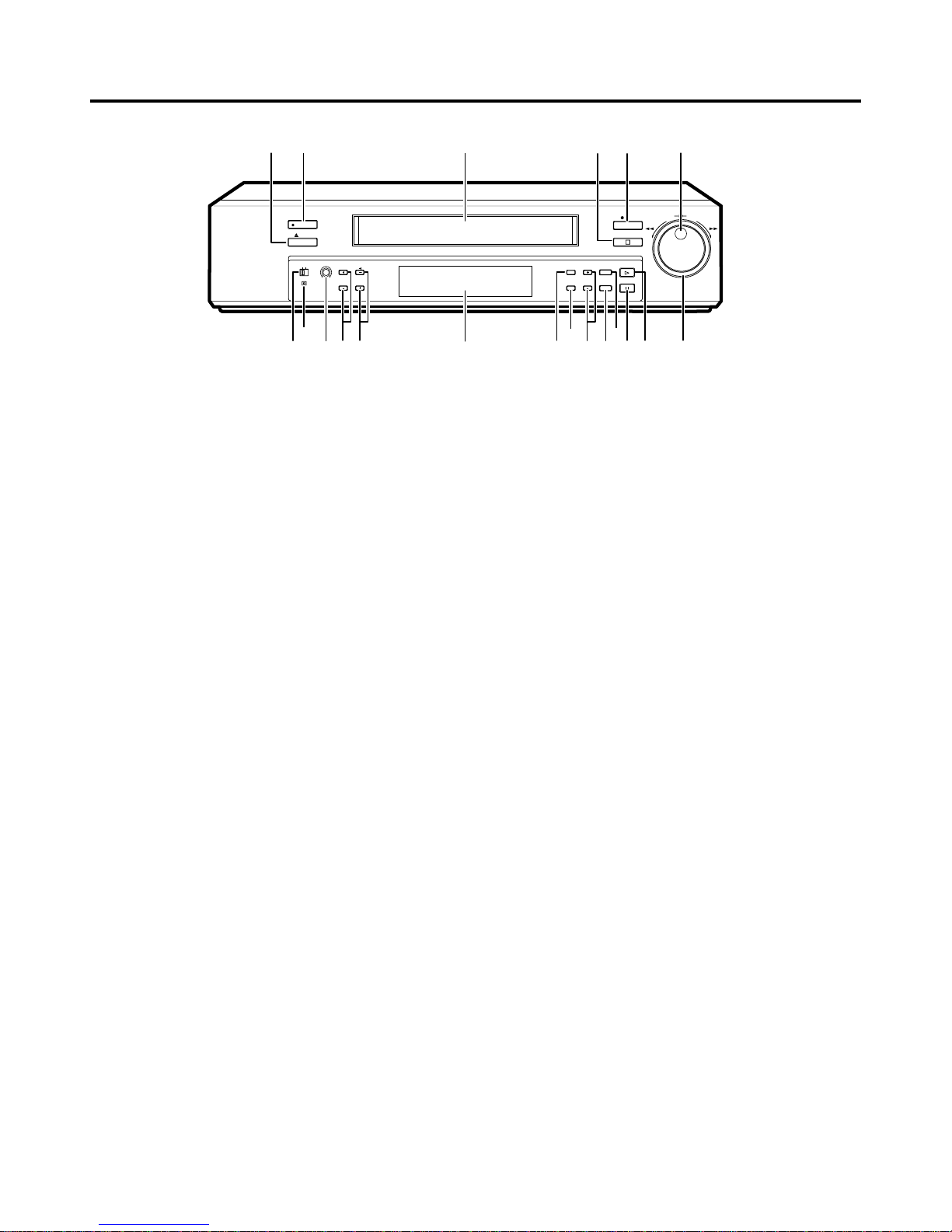
Fluorescent display
1 POWER button (Press for on; press again for off)
The POWER indicator illuminates when the VCR is
switched on.
2 EJECT button
Press to remove the cassette.
3 Cassette loading slot
Cassette tape is inserted in this slot for loading.
4 STOP button
Press to discontinue all tape related functions.
5 REC (RECORD) button
Press to begin recording.
6 JOG dial
Use to forward the tape frame-by-frame and to set the
menus.
7 SHUTTLE ring
Use to adjust the playback speed or to set the menus.
Turn this ring to the right to forward a tape or to forward
search. Tur n this ring to the left to rewind a tape or to
reverse search. Also, use to reset the alarm list, power
loss list and timer recording and to initialize the menu
settings.
8 PLAY button
Press to playback a previously recorded tape.
9 PAUSE/SHUTTLE HOLD button
When pressed during recording, tape movement stops
temporarily. Press again to continue the recording.
When pressed during playback, tape movement stops
and a still field is displayed. Press again to restore normal
playback. Pressing and holding this button after turning
the SHUTTLE ring allows continuous high speed playback
even if the SHUTTLE ring is released.
A COUNTER MEMORY/SKIP/INDEX button
Use to switch between COUNTER MEMOR Y(P.17), SKIP
SEARCH or INDEX SEARCH(P.22).
FEATURES AND FUNCTIONS
FRONT VIEW
B TIMER REC button
This button is pressed when a timer recording is to be
made.
C REC/PLAY MODE buttons
Set to 3H, L24H, 48H - 168H or 0H mode to select
recording speed in SP mode. Set to 3H, L24H, 24H, 48H
- 168H or 0H mode to select playback speed during
playback recorded in SP mode. Set to 6H, L18H, 48H 168H or 0H mode to select recording speed in LP mode.
Set to 6H, L18H, 48H - 168H or 0H mode to select
playback speed during playback recorded in LP mode.
D COUNTER RESET button
Press to reset the counter to “00000”.
E DISPLAY button
Press to display the MAIN MENU.
Press again to show the present time display.
F POSITION/VERTICAL ADJUST buttons
• When (+) button is pressed, the day and present time
display will move to the right. When the (-) button is
pressed, the day and present time will mov e down the
screen. Cannot be adjusted if a warning is displayed.
• Press these buttons to adjust for v ertical vibrations when
in still mode or during fast playback. Refer to pages 6
and 25 for more details.
G TRACKING buttons (+/-)
Press these buttons if noise is present during playback,
reverse playback or slow playback.
H PICTURE control
The picture quality can be adjusted between soft and
sharp.
I LOCK button
When pressed with a ball-point pen or a pencil, the unit
will be locked into the current mode and the operation
buttons will not operate. Release the lock by pressing
the lock button again.
J VIDEO switch
Use to select color or black and white recording and
playback.
1
2
4
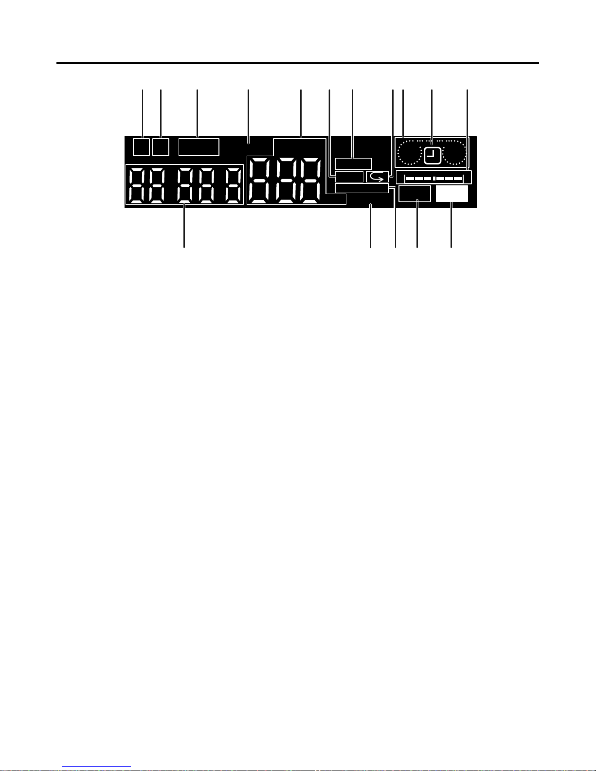
8 Repeat indicator
Illuminates when “TAPE END” in the “FIRST TIME SET
UP” menu is set to “REPEAT” or “ALARM•PROT”.
9 Cassette status indicator
Illuminates when tape is inserted. The light advances,
stops or flashes corresponding to the movement of the
tape.
A Timer recording indicator
Illuminates when the TIMER REC button is set to ON.
B Tape remaining indicator
Indicates the approximate tape position. S=Start,
E=End.
C REC indicator
Illuminates during recording.
D PLAY indicator
Illuminates during playback.
E EMGCY (EMERGENCY REC) indicator
Illuminates when “EMERGENCY REC” of the
“RECORDING SET UP” menu is set to “ON”.
F LOCK indicator
Lights when the Lock mode is set.
G COUNTER display
Indicates the relative position on the tape.
1 M (COUNTER MEMORY) indicator
Illuminates during rewind for counter memory mode.
2 PL (POWER LOSS) indicator
Illuminates when there is a power failure during recording.
3 ALARM indicator
Flashes during alarm recording and stays on when the
alarm recording is finished.
4 INDEX indicator
Flashes during recording of date/hour index signal at the
change of the hour, and during recording of the alarm
index signal. Lights during index search.
5 MODE display
Displays the selected recording or playbac k mode. During
index search, displays the index number. It will also
indicate the playback head selection, “SH” or “AH”, 3
seconds after the playback starts or if the playback mode
is changed. In the “FIRST TIME SET UP” menu, if the
“PB HEAD” selection is set to “L/L” or “R/R” then “SH” will
illuminate. If set to “AUTO”, then “AH” will illuminate.
N
• “SH” or “AH” lights during playback in SP mode ONLY.
6 SKIP indicator
Illuminates during skip search.
7 Record mode indicator
LP illuminates to indicate recording in LP mode or playing
back a tape recorded in LP mode. SP illuminates to
indicate recording in SP mode or playing back a tape
recorded in SP mode.
FLUORESCENT DISPLAY
PLAY
EMGCY
H
SKIP
SE
LOCK
M PL
SP LP
ALARM
INDEX
MODE
REC
12
3456
7A
9
G
ED
C
B
F
8
5
VIDEO
OUTIN
IN
OUTÉMIC
AUDIO
RESET
REMOTE
SET RSTINREC GND ALM MODE CLK CALL
OUT
1
A
9
87
6
5
4
3
2
EDC
B
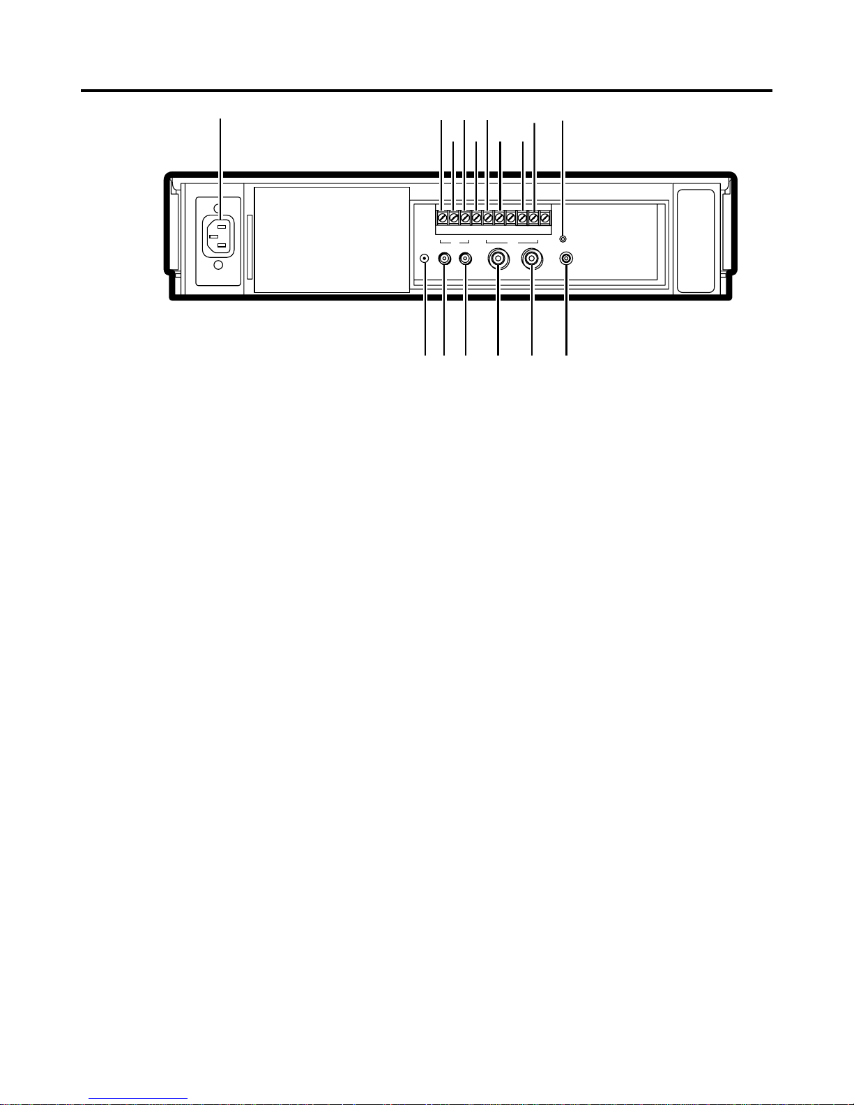
FEATURES AND FUNCTIONS
REAR VIEW
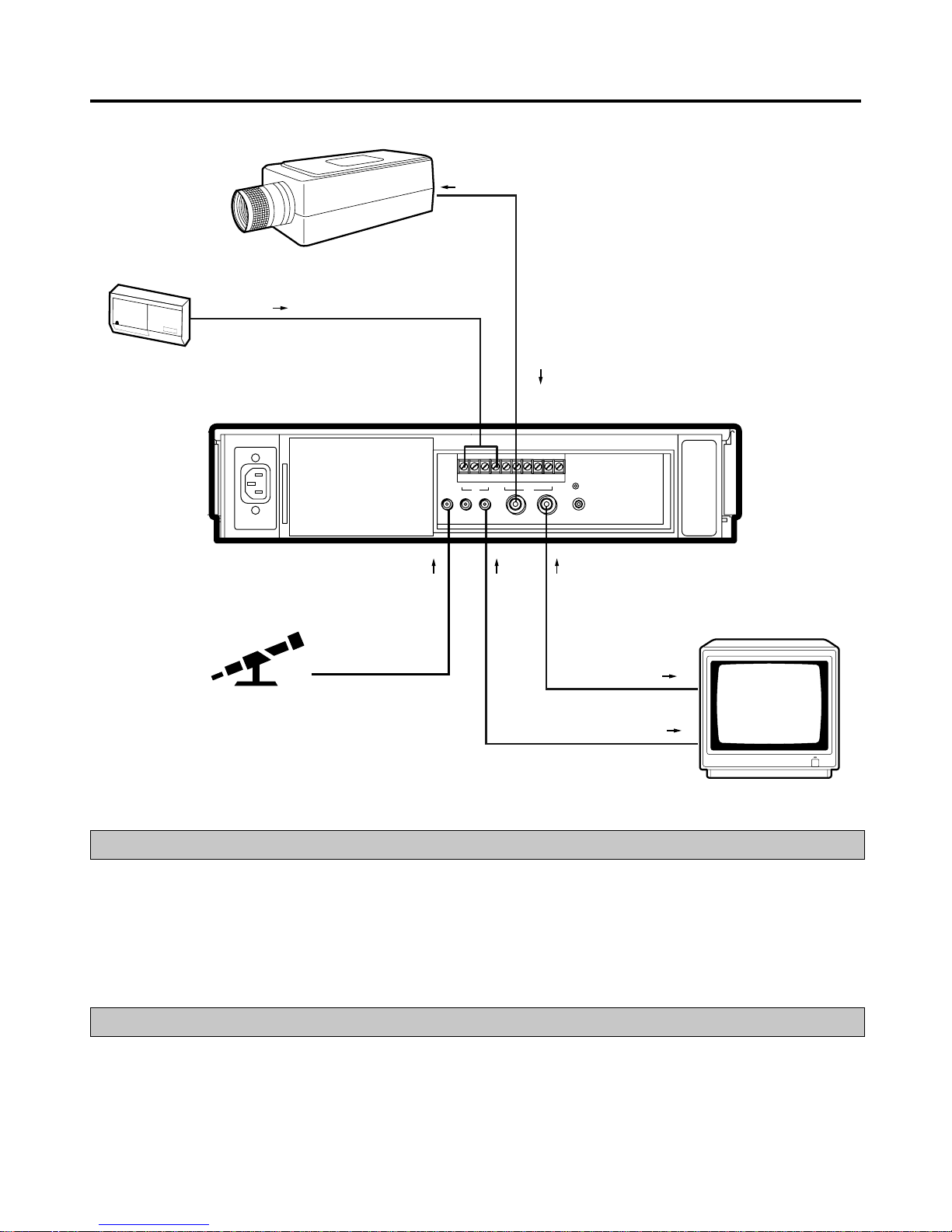
N
• Ensure the power cord is not plugged into the mains outlet before connecting to any rear terminals.
1 AC power socket
This socket connects to the power cord. Insert the cord
firmly.
2 SET IN terminal
Input terminal for alarm recording. The alarm sensor is
connected here.
3 RST (RESET) IN terminal
Input terminal to stop alarm recording when “ALARM REC
DURATION” of the “RECORDING SET UP” menu is set
to “MAN1”. The alarm reset switch is connected here.
This terminal can also be used to set the on-screen clock
when set to any mode other than “MAN1”.
4 REC IN terminal
Input terminal to start/stop recording. Also, use this
terminal for series recording (P.15) or synchronous
recording (P.16).
5 GND (GROUND) terminal
When a lead connected to other terminals requires a
ground, connect the ground lead here.
6 ALM (ALARM) OUT terminal
Output terminal to indicate alarm recording to an external
alarm.
7 MODE OUT terminal
Output terminal to indicate the VCR’s mode of operation.
Selected by setting “MODE OUT” on the “REAR
TERMINAL” menu.
8 CLK (CLOCK) OUT terminal
Output terminal to control an external camera switcher.
9 CALL OUT terminal
Output terminal to indicate when tape has finished
recording or if there has been a problem during recording.
A RESET button
When pressed, the present time, alarm recording list, power
loss list and the number of tape use will be erased. While
the button is pressed, the power is cut off from the VCR. If
there is a tape in the VCR and the button is released, the
power indicator will light and the tape will fast f orw ard for a
few seconds. The VCR will then switch off.
B REMOTE jack
Remote control is possible by connecting the optional
remote control unit (R-7100) here. Refer to page 29.
C VIDEO OUT connector
Output connector for video signal (BNC connector). If
the power switch is turned OFF, the signal from the VIDEO
IN connector is looped out to this connector.
D VIDEO IN connector
Input connector for video signal (BNC connector).
E AUDIO OUT connector
Audio output connector (RCA pin).
F AUDIO IN connector
Audio input connector (RCA pin).
G MIC IN jack
Input jack for a microphone with 600 ohms impedance.
FG
The VCR illustrations appearing in this manual
are of the HS-7168E(B).
6
CONNECTING WITH OTHER EQUIPMENT
AUDIO
OUT
MIC IN
VIDEO
OUT
VIDEO IN
AUDIO IN
MONITOR
SET IN
SENSOR
VIDEO
OUT
CCTV
CAMERA
VIDEO
IN
MIC
VIDEO
OUTIN
IN
OUTÉMIC
AUDIO
RESET
REMOTE
SET RSTINREC GND ALM MODE CLK CALL
OUT
VERTICAL ADJUSTMENT (Correcting picture vibration at the top and bottom)
The picture vibration can be reduced or eliminated by the following steps.
1 If the vibration occurs in still, slow motion, fast pla yback (x2) or normal playbac k in 24H - 168H or 0H mode, pla ybac k
a tape which is recorded in 3H or 6H mode with this VCR and press the PAUSE button.
If the vibration occurs during normal playback in L18H or L24H mode, playback a tape in each playback mode.
2 Press the VERTICAL ADJUST(+) or (-) button to reduce or eliminate the picture vibration.
MONITOR TO BE CONNECTED
• Connection with a CCTV monitor (for surveillance) is recommended.
• Connecting with some monitors may cause picture vibration and/or picture distortion at the top or bottom of the image
during still or normal playback.
A domestic Television Monitor may be unable to provide a stable picture without vibration and distortion.
7
11 – 11 – 98 09 : 21 : 01
<
RECORDING SET UP
>
3H
1M
OFF
NORMAL<SP>
1
SHOT
<
MAIN MENU
>
DISPLAY
TIME DATE SEARCH
TIMER PROGRAM
RECORDING SET UP
REAR TERMINAL
MAINTENANCE
FIRST TIME SET UP
Use JOG to select,
and ENTER.
Press DISPLAY to exit.
ALARM REC MODE
ALARM REC DURATION
EMERGENCY REC
REC MODE
ONESHOT•FIELD
ONESHOT•INTERVAL
<
REAR TERMINAL
>
WRNG•TAPE END
REC- 1
REC
SERIES
CALL OUT
CLOCK OUT
MODE OUT
REC IN
0
0H
<
MAINTENANCE
>
POWER LOSS LIST
ALARM LIST
ALL MENU INITIALIZE
POWER LOSS LIST CLEAR
ALARM LIST CLEAR
<
REPEAT REC TIMES
>
<
ELAPSED TIME
>
<
FIRST TIME SET UP
>
TAPE END
QUASI V-SYNC
TAPE LENGTH
PB HEAD SELECT
BUZZER
TIME DATE ADJUST
STOP
ON
E-180
NORMAL
WRNG
OFF
11
11
98
09 :21 : 01
<
TIME DATE SEARCH
>
15:00
23
FORWARD
TIME
DATE
DIRECTION
Use JOG to adjust,
and ENTER.
<
DISPLAY
>
1
SMALL
11 – 11 – 98 09 : 21 : 01
DISPLAY MODE
TIME DATE SIZE
Ex.
<
MODE 1
>
<
TIMER PROGRAM
>
DW START END HR
SPL 08 : 40 17 : 10 L18LP
2 SAT 08 : 40 12 : 20 L18LP
3 WED 22 : 00 22 : 54 3SP
4 - - - - - : - - - - : - - - - 5 - - - - - : - - - - : - - - - 6 - - - - - : - - - - : - - - - 7 - - - - - : - - - - : - - - - 8 - - - - - : - - - - : - - - - -
SPECIAL DW MON–FRI
<
ALARM LIST
>
ALL MENU INITIALIZE
Turn the SHUTTLE RING <<
then all MENU will be
initialized.
POWER LOSS LIST CLEAR
Turn the SHUTTLE RING <<
then POWER LOSS LIST
will be cleared.
ALARM LIST CLEAR
Turn the SHUTTLE RING <<
then ALARM LIST will be
cleared.
0001 05 - 01 - 98 01 : 00
0002 07 - 01 - 98 21 : 10
0003 10 - 01 - 98 09 : 15
<
POWER LOSS LIST
>
01 03 - 01 - 98 01 : 00
02
03
DAYLIGHT SAVINGS
MONTH
DATE
YEAR
TIME
<
TIME DATE ADJUST
>
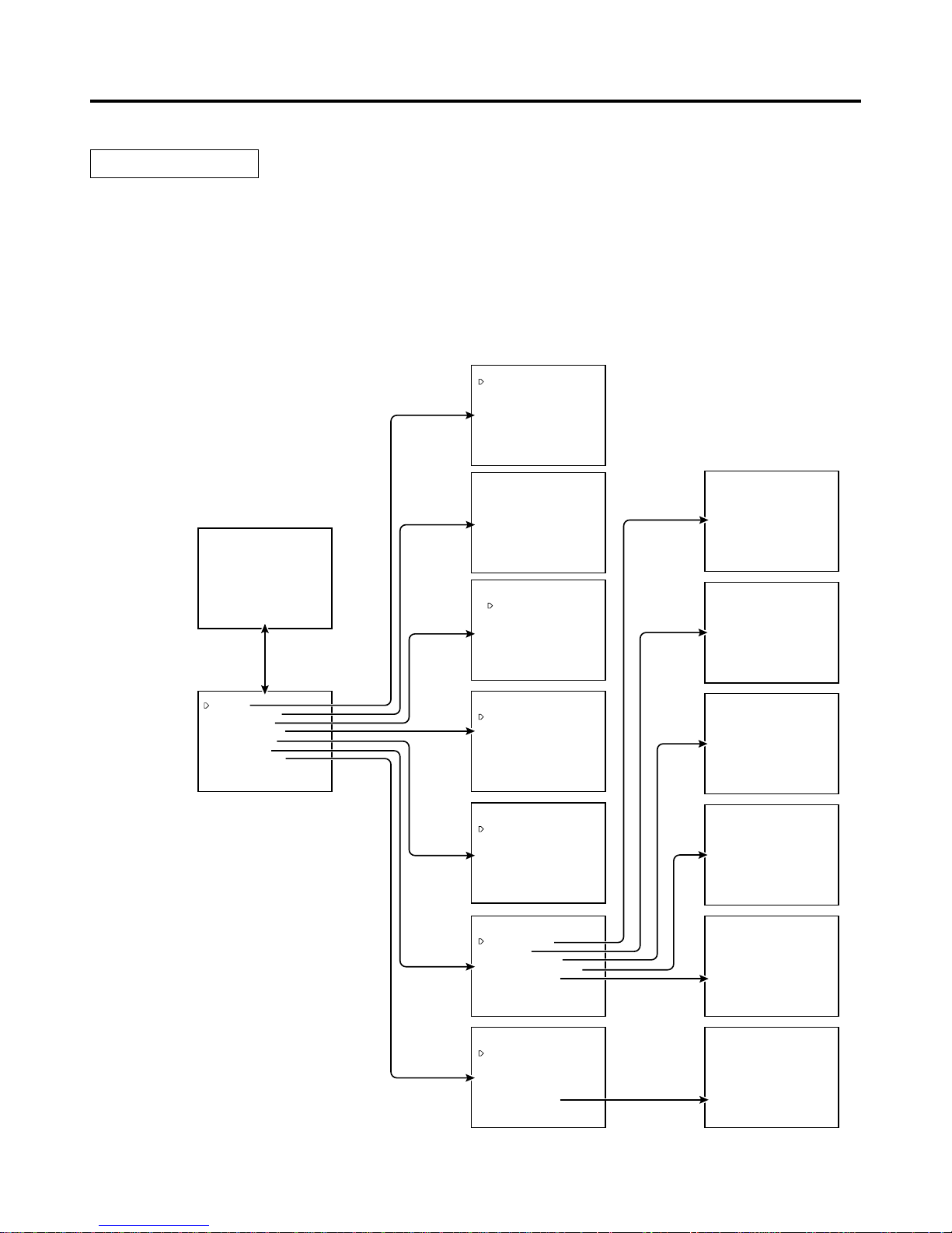
SETTING THE MENUS
1 Press the DISPLAY button.
• The “MAIN MENU” is displayed.
2 Turn the JOG dial to select the desired item.
• When the JOG dial is turned to the right, the cursor moves downward.
• When the JOG dial is turned to the left, the cursor moves upward.
3 Turn the SHUTTLE ring to the right.
The desired item is selected and the menu will appear.
4 Turn the JOG dial to select item.
5 Turn the SHUTTLE ring to the right and the setting item will flash.
6 Turn the JOG dial to change the setting.
7 Turn the SHUTTLE ring to the right to set.
8 Press the DISPLAY button.
• The present time display will appear.
The operating parameters of this VCR are set through various on-screen menus.
Set the menus as follows:
OPERATION
present time
display
8
<
MAIN MENU
>
DISPLAY
TIME DATE SEARCH
TIMER PROGRAM
RECORDING SET UP
REAR TERMINAL
MAINTENANCE
FIRST TIME SET UP
Use JOG to select,
and ENTER.
Press DISPLAY to exit.
<
DISPLAY
>
1
SMALL
11 – 11 – 98 09 : 21 : 01
DISPLAY MODE
TIME DATE SIZE
Ex.
<
MODE 1
>
<
TIME DATE SEARCH
>
15:00
23
FORWARD
TIME
DATE
DIRECTION
Use JOG to adjust,
and ENTER.
<
RECORDING SET UP
>
3H
1M
OFF
NORMAL<SP>
1
SHOT
ALARM REC MODE
ALARM REC DURATION
EMERGENCY REC
REC MODE
ONESHOT•FIELD
ONESHOT•INTERVAL
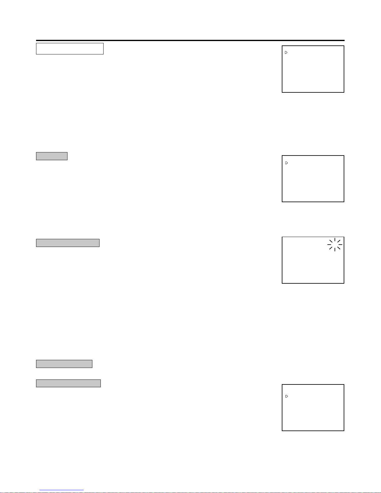
MAIN MENU
1 DISPLAY
Sets the display format of the date and present time on the monitor.
2 TIME DATE SEARCH
Sets the date, time and direction to search for the desired part of a tape.
3 TIMER PROGRAM
Sets the timer recording.
4 RECORDING SET UP
Sets the alarm recording mode, alarm recording duration, emergency recording, recording mode and one-shot recording.
5 REAR TERMINAL
Sets the frequency division ratio of CLOCK OUT, output signal of the CALL OUT terminal and the MODE OUT terminal, etc.
6 MAINTENANCE
Displays the power loss list and alarm loss list, etc. and initialises all menu settings. Clears the power loss list and alarm list.
7 FIRST TIME SET UP
Set up for when the end of the tape is reached, quasi v-sync, tape length, pla yback head selection, buzzer setting, present time.
DISPLAY
1 SETTING THE DISPLAY MODE (DISPLAY MODE)
DISPLAY MODE 1: Displays date and present time. (Refer to page 11.)
DISPLAY MODE 2: Displays date, day of the week, present time and recording mode. (Refer to
page 11.)
DISPLAY MODE 3: Displays nothing; until an alarm recording starts, then date, alarm recording
number, etc. is displayed.
DISPLAY MODE 4: Displays nothing; even in the case of alarm recording, nothing is displayed
on the monitor.
• During an alarm recording, alarm recording number is displayed if the “DISPLAY MODE” is set from 1 to 3.
2 SETTING THE SIZE OF THE LETTERS OF DAY AND PRESENT TIME DISPLAY (TIME DATE SIZE)
SMALL: The size of the letters becomes small.
LARGE: The size of the letters becomes large.
TIME DATE SEARCH
Sets the date, time and direction to search for the desired location on a tape.
1 SETTING THE TIME Turn the JOG dial to set the hour and minute to search for.
2 SETTING THE DA TE Turn the JOG dial to set the day of the month to search for.
3 SETTING THE DIRECTION Turn the JOG dial to select the starting direction for search.
FORWARD: Search in the forward direction.
REVERSE: Search in the reverse direction.
• If the desired part of a tape is not found in one direction, the VCR automatically searches in the opposite direction.
After the setting, turn the SHUTTLE ring to the right to start searching.
N
• An hour index mark is written on the tape on the hour and is used as a reference in the search function. Because of this, a
recorded tape must pass a time clock hour mark before this function can work. The TIME DATE SEARCH function begins after
the first hour index mark.
Example 1: VCR is set to record from 8:30 to 17:30 - Times from 9:00 to 17:30 can be found.
Example 2: VCR is set to record in one speed from 7:00 to 14:30, then in another speed until 18:00 - Times from 7:00 to 14:30
and 15:00 to 18:00 are accurately located.
• Time date search function is not available for a tape recorded by any other VCR than this model.
• If recording quality is poor, the VCR may fail to locate the desired part of the tape during time date search.
TIMER PROGRAM
Refer to page 18 “TIMER RECORDING” for details.
RECORDING SET UP
1 SETTING THE ALARM REC MODE (ALARM REC MODE)
Sets the alarm recording time mode. When the JOG dial is turned, the display will be switched in the
order of 3H } 6H } L18H } L24H } 3H } ....
2 SETTING THE ALARM REC DURATION (ALARM REC DURATION)
Sets the duration of the alarm recording period. When the JOG dial is turned, the display will be
switched in the order of 1M(minute) } 2M } 5M } 10M } MAN1 } MAN2 } 15S(second) } 30S
} 45S } 1M } .... Refer to “ALARM RECORDING” on page 20.
3 SETTING THE EMERGENCY REC (EMERGENCY REC)
Sets the emergency recording mode.
OFF: Starts alarm recording when the alarm signal is received during recording.
ON: Starts alarm recording when the alarm signal is received not only during recording but also when the power is OFF or
when the tape is stopped.
9
CALL OUT
setting
TAPE END
setting
WRNG•TAPE END
WRNG
STOP
Outputs a call signal at
the end of the tape
Outputs a call signal at the end
of the tape for 2 seconds
Outputs a call signal at the
end of the tape
When a malfunction occurs in the VCR
during recording, a call signal is output.
REWIND
REPEAT
ALARM
• PROT
When there are no
alarm recordings
during recording
When there are alarm
recordings during
recording
WRNG•REMAIN
Outputs 3 minutes before
the tape end
SETTING THE MENUS
<
REAR TERMINAL
>
WRNG•TAPE END
REC- 1
REC
SERIES
CALL OUT
CLOCK OUT
MODE OUT
REC IN
4 RECORDING MODE (REC MODE)
Sets the recording mode.
NORMAL<SP> : Choose when higher picture quality is preferred. With this setting, the recording time mode is s witched in the order of
3H } L24H } 48H } 72H } 96H } 120H } 168H } 0H } 3H ...
H•D<LP> : Select a LP setting to perform High Density recording. This provides 2x more fields than Normal Density(SP). It
reduces the time interval between pictures, providing more pictures for smoother time lapse recording. With this
setting, the recording time mode is switched in the order of 6H } L18H } 48H } 72H } 96H } 120H } 168H }
0H } 6H ...
5 SETTING THE NUMBER OF FIELDS IN ONE-SHOT RECORDING (ONE SHOT•FIELD)
Sets the number of recorded fields in the one-shot recording mode. When the JOG dial is turned to the right, the display will be
switched in the order of 1 } 2 } 3 } 4 } 5 } 10 } 20 } 30 } 1 }....
6 SETTING THE INTERVAL TIME IN THE ONE-SHOT RECORDING MODE (ONE SHOT•INTERVAL)
Sets the interval time in the one-shot recording mode. When the JOG dial is turned to the right, the display will be switched in the
order of SHOT } 10S (second) } 15S } 30S } 45S } 1M } 2M } 3M } SHOT }....
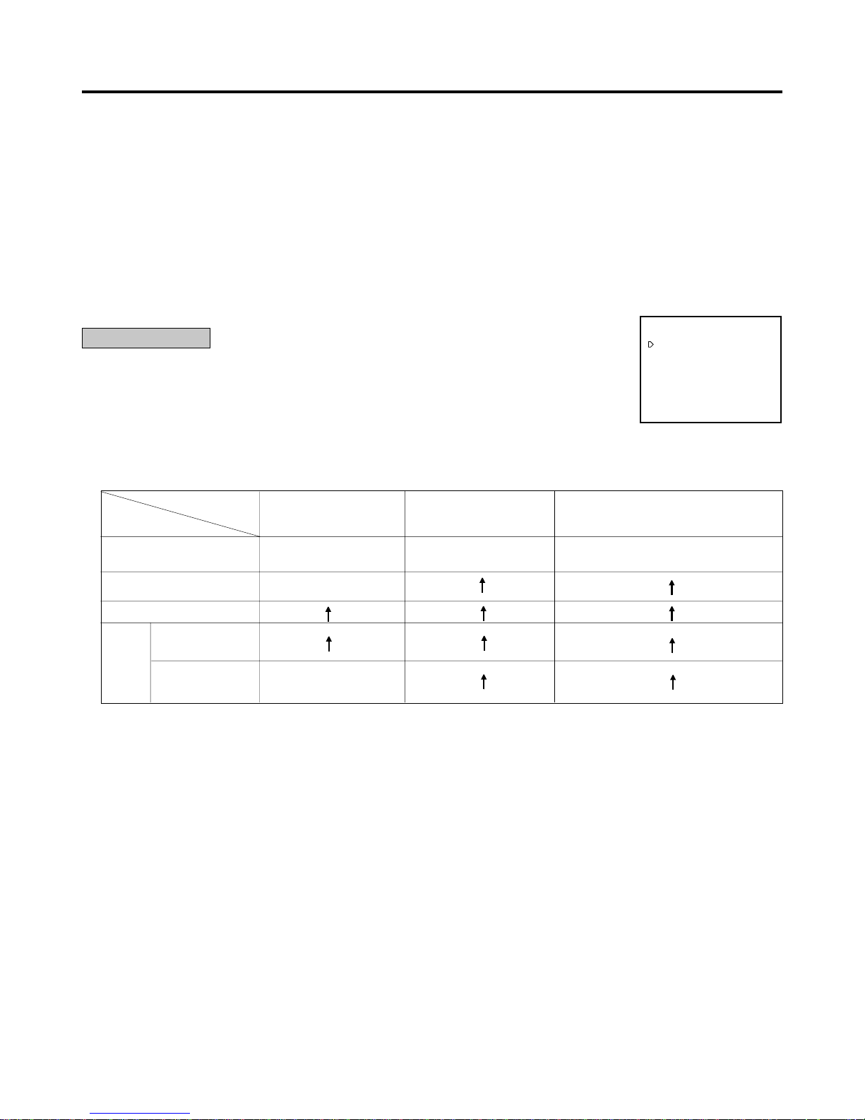
REAR TERMINAL
1 SETTING THE CALL SIGNAL OUTPUT AT THE END OF THE TAPE (CALL OUT)
Enables or disables the signal that is output from the CALL terminal when the end of the tape is
reached during recording. If any abnormalities occur during recording, a CALL signal is output from
the CALL terminal on the rear panel regardless of CALL OUT setting.
WRNG•TAPE END: A signal is output at the end of the tape or when a malfunction occurs.
WRNG•REMAIN: The signal is output when a malfunction occurs in this VCR or when the tape
has approximately 3 minutes left in 3H mode.
WRNG: When a malfunction occurs in the VCR during recording, a CALL signal is output.
This is used in conjunction with TAPE END (FIRST TIME SET UP) to determine when the CALL signal is output as shown below.
2 SETTING THE FREQUENCY DIVISION RATIO (CLOCK OUT)
Sets the frequency division ratio of the CLOCK OUT terminal.
First, set the recording mode for the “CLOCK OUT” pulse output in the “REAR TERMINAL” menu.
REC: When recording in any mode.
T/L-REC: When recording in time lapse mode (L18H, L24H, 48H, 72H, 96H, 120H, 168H or 0H).
Second, select the frequency division ratio setting by turning the SHUTTLE ring. When the JOG dial is turned, the display will be
switched in the order of 1 } 2 } 3 } 4 } 5 } 10 } 15 } 20 } 25 } 30 } 50 } 60 } F (field) } 1 } ... The numbers from 1 to
60 indicate the number of frames in 3H or 6H recording mode or the number of fields in time lapse recording mode. (One frame
consists of two fields.) One field is selected when it is set to “F” (field).
3 SETTING THE OPERATION MODE OF THE MODE OUTPUT TERMINAL (MODE OUT)
Set the state in which the signal output at the MODE OUT terminal is switched to the active condition. When the JOG dial is turned,
the display will be switched on in the order of REC (recording) } PLAY (playback) } POWER (power “ON”) } TAPE IN (tape is
inserted) } TAPE REMAIN (3 minutes in 3H mode before the tape end) } CLOCK ADJ (output the signal for 1 second when the
clock indicates “00(min.):00(sec.)”) } REC.
4 SETTING THE OPERATION MODE OF THE REC IN TERMINAL (REC IN)
SERIES: Recording starts when the REC IN terminal is short-circuited to ground or a “L” level voltage (0 - +1.6V) is applied.
REC-START/ STOP: Recording starts when the REC IN terminal is shor t-circuited to ground or a “L” level voltage (0 - +1.6V) is
applied. Should this connection be removed, recording will stop.
SYNC REC: The video signal from 3 or 9 cameras can be recorded separately by connecting the switcher. (“SYNC REC” function
is available when recording in L18H or L24H mode.) Refer to “SYNCHRONOUS RECORDING” on page 16.
 Loading...