

)..
MITSUBISHI
AUTO-TRACKING
WITH
Dl.GITAL CONTROL
COLOR DISPLAY MONITOR
~
~ODEL
I
HL7925K
SERIES
USER'S GUIDE
For future reference, record the serial
number of your display monitor
space
below:~---------,
SERIAL
The serial number
cover
No.
'---------~
is
located on the rear
of
the set.
~i:
~
*ii'ti(H'}@l~~.&
ff~~~
M~%,
ilJ
,CAUTION
Japanese
and
(xLH9:#'5)
~5:£(:£-,
t.J'i'.'¥ ·r-9 0
These
products
and/
diversion
U'9}@lm~~!Ud:~d>
'=~~irnt:N>,
·
<
ftit±J
or
technologies
or
COCOM
contrary
strategic
thereto
(x(;H9:#'5lX51)
ftit±19
are
subject
restrictions,
is
prohibited
in
the
.Q
~f
to
.
CAUTION
• The line cord and plug designed for safety is provided with this set.
It is to
shock.
•Do
and other hazards.
\.
6e
used with a properly grounded power receptacle to avoid possible electrical
not remove the back cover of the set
as
this can expose you to very high voltages
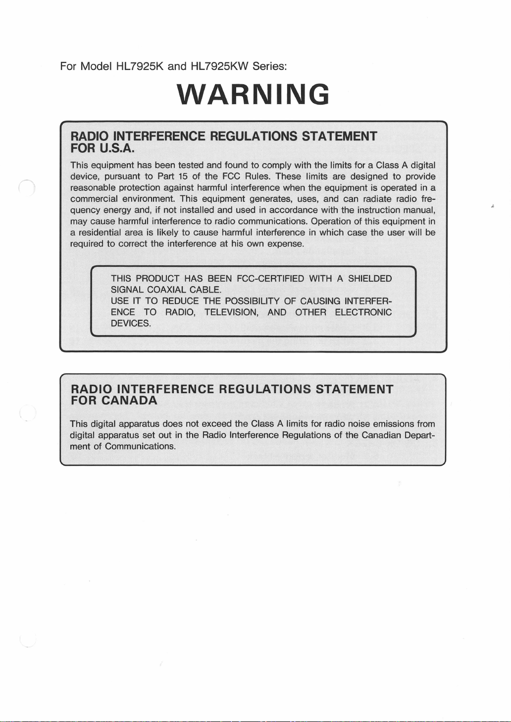
For Model HL7925K and HL7925KW Series:
WARNING
RADIO INTERFERENCE REGULATIONS STATEMENT
FOR U.S.A.
This equipment has been tested and found to comply with the limits for a Class A digital
device, pursuant to Part
reasonable protection against harmful interference when the equipment is operated
commercial environment. This equipment generates, uses, and can radiate radio frequency energy and, if not
may cause harmful interference to radio communications. Operation of this equipment
a residential area is likely to cause harmful interference
required
to
correct the interference at his own expense.
15
of the
installed and used in accordance with the instruction manual,
FCC
Rules. These limits are designed to provide
in
which case the user will be
in
a
in
THIS PRODUCT HAS
SIGNAL COAXIAL
USE
IT TO
REDUCE
ENCE
DEVICES.
RADIO
FOR
This digital apparatus does not exceed the Class A limits for radio noise emissions from
digital apparatus set out in the Radio
ment of Communications.
CANADA
TO RADIO, TELEVISION,
INTERFERENCE REGULATIONS
BEEN
FCC-CERTIFIED WITH A SHIELDED
CABLE.
THE POSSIBILITY
Interference Regulations
OF
CAUSING INTERFER-
AND
OTHER ELECTRONIC
STATEMENT
of
the Canadian Depart-
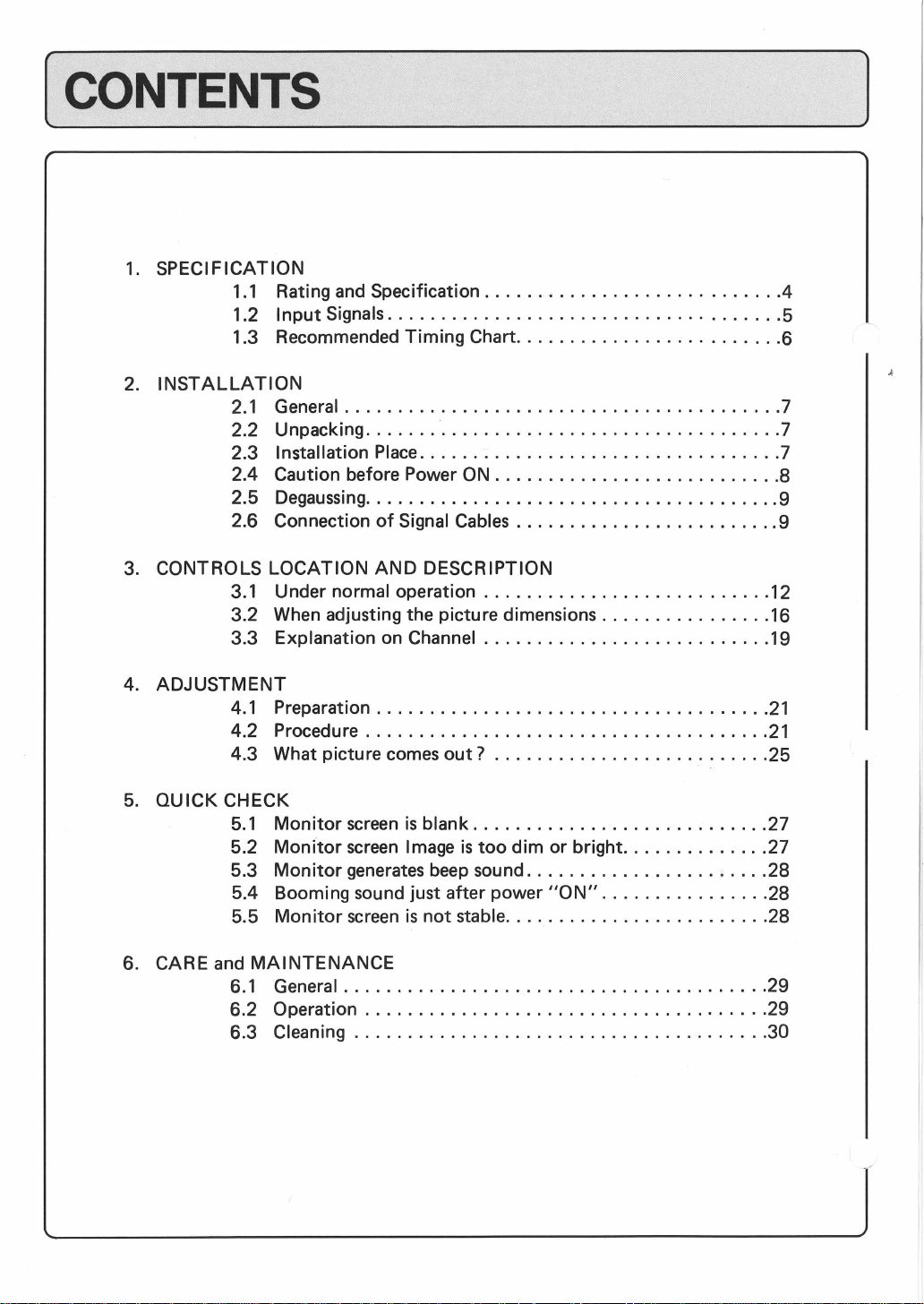
(CONTENTS
1.
SPECIFICATION
1.1
Rating
1.2
Input
1.3 Recommended Timing Chart
2.
INSTALLATION
2.1
General
2.2
Unpacking
Installation
2.3
2.4 Caution before Power
Degaussing
2.5
2.6 Connection
3.
CONTROLS LOCATION
3.1
Under normal operation
3.2 When adjusting the picture dimensions
3.3 Explanation on Channel
and
Signals
.........................................
....... -................................
.......................................
Specification
.....................................
Place
..................................
of
Signal
AND
DESCRIPTION
......•....................
.........................
ON
...........................
Cables
.........................
...........................
...........................
................
]
.4
5
6
7
7
7
8
9
9
12
16
19
4.
ADJUSTMENT
4.1
4.2 Procedure
4.3 What picture comes
5.
QUICK CHECK
5.1
5.2
5.3
5.4 Booming sound just after power
5.5
6. CARE and
6.1
6.2 Operation
6.3 Cleaning
Preparation
Monitor
Monitor
Monitor
Monitor
MAINTENANCE
General
.....................................
......................................
screen
screen
generates
screen
........................................
......................................
.......................................
is
blank
Image
beep
is
not
out?
..........................
............................
is
too
dim or bright
sound
.......................
"ON"
stable
.........................
..............
................
21
21
25
27
27
28
28
28
29
29
30

(
1.
SPECIFICATIONS
1.1
Rating
1)
AC
POWER VOLTAGE
2)
3)
4)
5)
6)
7)
8)
9)
1
0)
11)
12)
13)
14)
15)
16)
17)
18)
19)
20)
and Specification
AC POWER FREQUENCY
POWER CONSUMPTION
INPUT SIGNAL
VIDEO
SYNC.
INTERFACE
a)
INPUT CONNECTOR
b)
INPUT IMPEDANCE
SCANNING FREQUENCY
PRE-SET TIMING
WARM
EFECTIVE DISPLAY AREA
BRIGHTNESS
VIDEO
BLANKING TIME
LINEARITY
RASTER DISTORTION
RASTER SIZE REGULATION
MISS CONVERGENCE
HIGH
TEMPERATURE
OUTLINE SIZE
WEIGHT
UP
TIME
AMPLIFIER
VOLT AGE
MODEL
HL7925
*K
HL7925*KV
HL7925*KW
50/60
Hz
150 w (typ)
Analog R,G,B
Composite sync. on Green :
Composite ext. sync.
Separate sync. (HD/VD)
BNC (Receptacle)
75.0 for video and sync. signal
High impedance can be selected by Impedance
SW.
Select
Loop-through operation is available with T-type
BNC connector.
HORIZONTAL 30 kHz
VERTICAL 50
See the recommended timing chart specification. (page
More than 30 minutes.
360
(W)
X 270
100 nit with STD CRT, standard white window
video signal.
50
Hz,.....,
120
Horizontal
Vertical <
Better than
Note; H-LIN will be specified for
Less than 2.0%
Less than 0.5%
Center (Within 270
Other area
27 kV
O
,.....,
498
Approx. 33 kg
5540-55
30-40
FH
=30-37
-0.5
(STD)
40°C (with standard cabinet)
(W)
x 449
Hz
(H)
mm
MHz±3
78 kHz < 3.2µsec
kHz <
kHz < 6.0µsec
7%
/47-52/60-64
mm
mm
(H)
X 534
RATING
AC100-120V
AC 220
"'240V
AC
100"'
220,.....
AC
0.7 Vp-p (Positive)
0.7 Vp-p (Negative)
1.5
1
5
·
,.....,
78 kHz
,.....,
120
Hz
dB
Tr/Tf<6
5.0µsec
600µsec
kHz/75
diameter circle)
(Typ)
(D)
(with standard cabinet)
120 V
240V
,.....,
5 Vp-p (Negative)
V _ (Positive )
,.....,
5
P P Negative
nsec
,.....,
78
-0.35
mm
(Typ)
]
6)
4
[~s_P_E_C_IF_IC_A_Tl_O_N
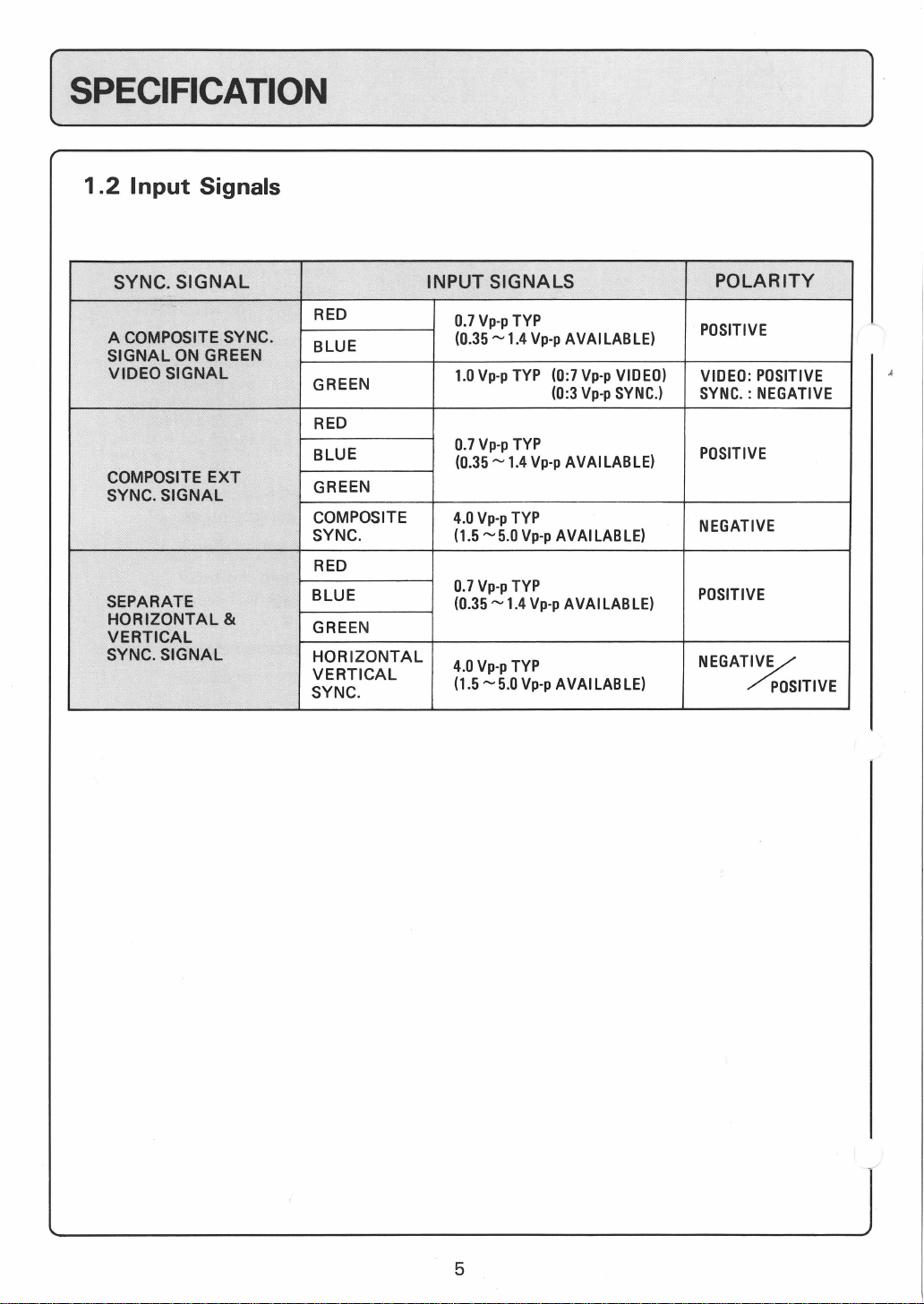
1.2
Input
Signals
____________________
]
SYNC. SIGNAL INPUT SIGNALS
A COMPOSITE SYNC.
SIGNAL
VIDEO SIGNAL
COMPOSITE EXT
SYNC. SIGNAL
SEPARATE
HORIZONTAL &
VERTICAL
SYNC. SIGNAL
ON
GREEN
RED
BLUE
GREEN
RED
BLUE
GREEN
COMPOSITE
SYNC.
RED
BLUE
GREEN
HORIZONTAL
VERTICAL
SYNC.
0.7
Vp-p
(0.35,.....,
1.0
Vp-p
0.7
Vp-p
(0.35,.....,
4.0
Vp-p
(1.5
,.....,5.0
0.7
Vp-p
(0.35,.....,
4.0
Vp-p
(1.5,.....,
5.0 Vp-p AVAi
TYP
1.4
TYP
TYP
1.4
TYP
Vp-p
TYP
1.4
TYP
Vp-p
(0:7
(0:3
Vp-p
Vp-p
AVAi
LAB
LE)
Vp-p
VIDEO)
Vp-p
SYNC.)
AVAILABLE)
AVAILABLE)
AVAi
LAB
LE)
LAB
LE)
POLARITY
POSITIVE
VIDEO:
SYNC. : NEGATIVE
POSITIVE
NEGATIVE
POSITIVE
NEGAT%
POSITIVE
POSITIVE
5
(
1
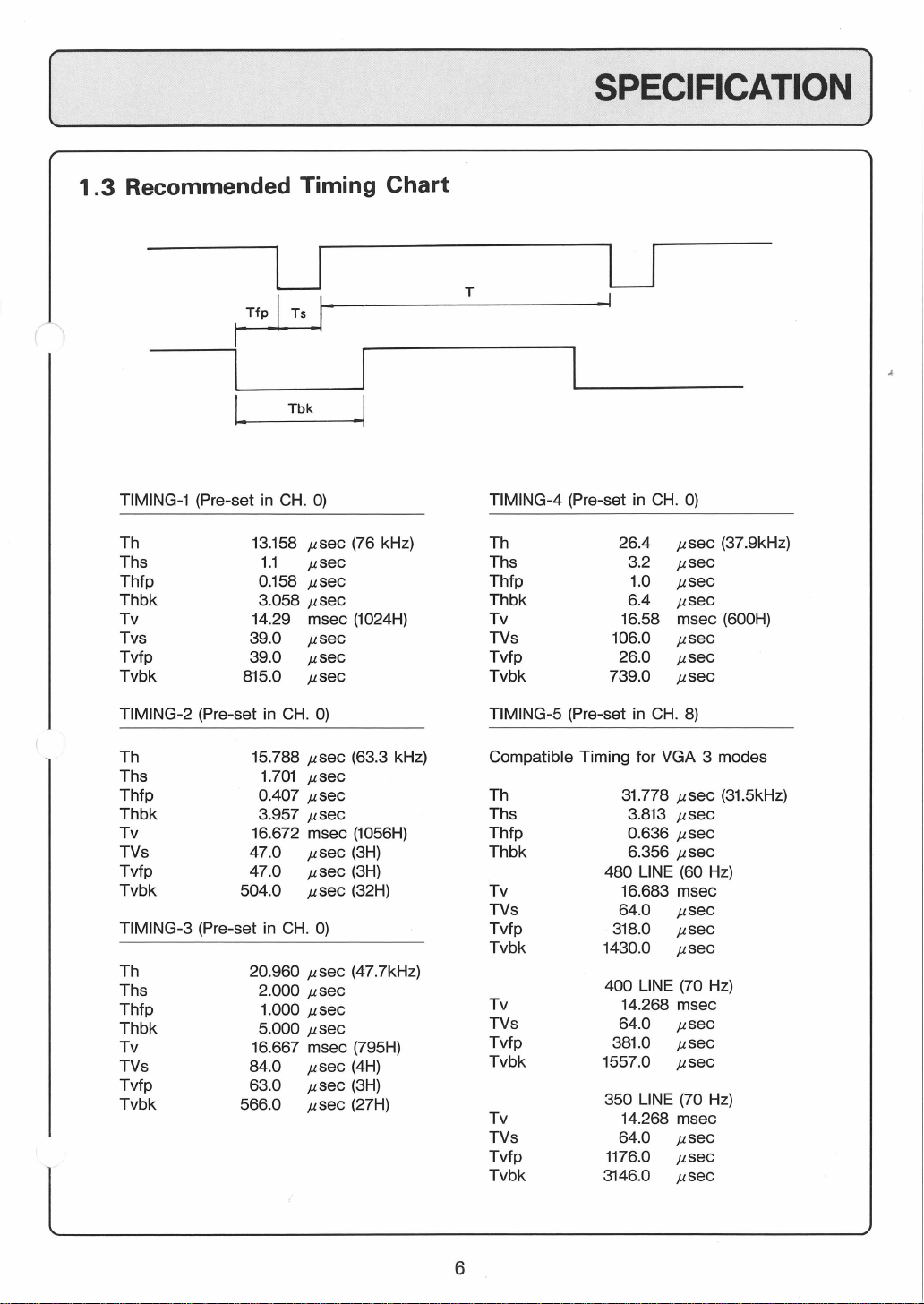
.3
Recommended Timing
Chart
SPECIFICATION
]
TIMING-1 (Pre-set
Th 13.158
Ths
Thfp 0.158
Thbk
Tv 14.29
Tvs
Tvfp
Tvbk
TIMING-2 (Pre-set in
Th
Ths
Thfp
Thbk
Tv
TVs
Tvfp
Tvbk
TIMING-3 (Pre-set in
Th 20.960
Ths
Thfp 1.000
Thbk
Tv
TVs
Tvfp 63.0
Tvbk
in
CH.
1.1
3.058
39.0
39.0
815.0
CH.
15.788
1.701
0.407
3.957
16.672 msec
47.0
47.0
504.0
CH.
2.000
5.000
16.667 msec (795H)
84.0
566.0
0)
µsec
µsec
µsec
µsec
msec
µsec
µsec
µsec
0)
µsec
µsec
µsec
µsec
µsec
µsec
µsec
0)
µsec
µsec
µsec
µsec
µsec
µsec
µsec
(76 kHz)
(1024H)
(63.3 kHz)
(1056H)
(3H)
(3H)
(32H)
(47.7kHz)
(4H)
(3H)
(27H)
T
TIMING-4 (Pre-set in
Th 26.4
Ths 3.2
Thfp
Thbk
Tv
TVs 106.0
Tvfp
Tvbk
TIMING-5 (Pre-set
Compatible Timing for VGA 3 modes
Th
Ths 3.813
Thfp
Thbk
Tv
TVs
Tvfp
Tvbk
Tv 14.268 msec
TVs
Tvfp
Tvbk
Tv
TVs
Tvfp
Tvbk
LJ
CH.
0)
µsec
µsec
1.0
µsec
6.4
µsec
in
CH.
778
0.636
6.356
msec
µsec
µsec
µsec
8)
µsec
µsec
µsec
µsec
Hz)
µsec
µsec
µsec
µsec
µsec
µsec
Hz)
µsec
µsec
µsec
16.58
26.0
739.0
31.
480 LINE (60
16.683 msec
64.0
318.0
1430.0
400 LINE (70 Hz)
64.0
381.0
1557.0
350 LINE (70
14.268 msec
64.0
1176.0
3146.0
(37.9kHz)
(600H)
(31.5kHz)
6
(_2_.l_NS_Ti_A_LL_A_~l_O_N
__________
)
2.1 General
This section explains
operation. The
but
it
may require certain
generator
ances
other basic checks
simple procedures should
2.2
Unpacking
The
MITSUBISHI ELECTRIC CORPORATION.
Open the
out
the
Accessories
materials.
2.3
Installation Place
· The
magnetic fields,
cause
• The sufficient ventilation
do
or
other
caused during transportation. Complete adjustment procedures and
monitor
monitor
monitor
the miss-convergence.
not
is
top
of
are
block the vents
how
to
install the
monitor
normally packaged in a separated shipping container
container, then remove the inside packing materials and
car~fu
placed at the
should
is
throughly
minor
controller
are
described in section 4, and section 5,
I ly.
eg.
and
be
necessary
bottom
be
placed away
transformer and
is
necessary
of
cabinet.
monitor
adjusted and checked
adjustments
to
compensate
for
of
to
adapt
initial
container, and/or the
from
motor,
for
installation.
the device which generates the
long
and
for
minor
because
time
how
to
verify its basic
out
at the factory,
it
to
a particular display
adjustment disturb-
but
only
selected
top
of
packing
the magnetic fields
stable operation. So,
by
lift
· In order
recommended
to
get the excellent display image and prevent eye fatigue,
to
avoid the
direct
light shining
7
to
the
screen
of
monitor.
it
is
[
INSTALLATION ]
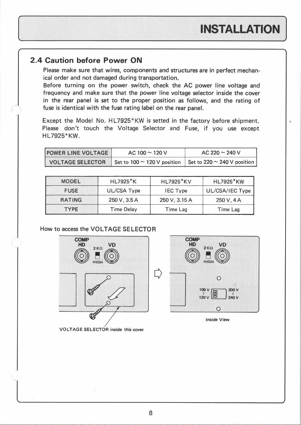
2.4
Caution before
Please
ical order and
Before turning on the power. switch, check the AC power line voltage and
frequency and make sure
in the rear panel
fuse
make sure
is
identical
not
Power
that
wires, components and structures
damaged during transportation.
is
set
to
with
the
fuse
ON
that
the power line voltage selector inside the cover
the proper position
rating label on the rear panel.
are
in
perfect mechan-
as
follows, and the rating
of
Except the Model No. H
Please
HL7925*KW.
POWER
How
don't
LINE
VOLTAGE
MODEL
FUSE
RATING
TYPE
to
access
touch the Voltage Selector and Fuse,
VOLTAGE
SELECTOR
the
VOLTAGE
COMP
HD
· VD
0:~:~
L7925*
Set
to
HL7925*K
UL/CSA
250V,
3.5A
Delay
Time
SELECTOR
KW
AC
100"'
Type
is
setted in the factory before shipment.
if
you
100"'
120 V AC
120 V position
HL7925*KV
IEC Type
250 V, 3.15 A
Time
Set
Lag
COMP
HD
to
220"'
UL/CSA/I
220"'
240 V position
HL7925*KW
250V,4A
Time
VD
0:~:0
0
use
240 V
EC
Lag
except
Type
J
~__,_/
VOLTAGE
SELECTOR
/c
inside this cover
1oov[[J200v
l a l
120 v
ill]
240 v
0
-
Inside
View
8
[ INSTALLATION
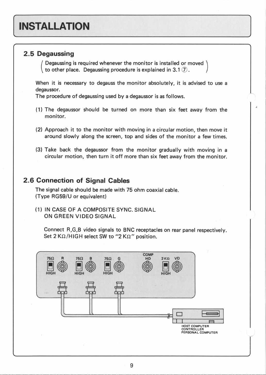
2.5
Degaussing
]
Degaussing
(
to
other place.
When
degaussor.
The procedure
(
(2) Approach
(3) Take back the degaussor
2.6
Connection of Signal Cables
The signal cable should
(Type RG59/U
(1) IN CASE OF A COMPOSITE SYNC.
it
1)
The degaussor should
monitor.
around slowly along the screen,
circular
ON GREEN
is
necessary
it
motion,
is
required whenever the
Degaussing
to
degauss
of
degaussing
to
the
then
or
equivalent)
VIDEO
used
be
monitor
turn
be
made
SIGNAL
monitor
procedure
the
by
turned on more than six feet away
with
from
it
off
with
is
monitor
a degaussor
moving in a circular
top
and
the
monitor
more than six feet away
75 ohm coaxial cable.
SIGNAL
is
installed
explained in
absolutely,
is
as
follows.
sides
of
the
gradually
or
3.1
(J).
it
is
motion,
monitor
with
from
moved )
advised
then move
a few times.
moving in a
the
to
use
from
the
monitor.
a
it
Connect R,G,B video signals
Set 2
Kn/HIGH
15Q
R
~~
HIGH
select
SW
75Q B
~~
HIGH
to
75Q . G
~~
HIGH
to
BNC receptacles on rear panel respectively.
"2
Kn"
position.
COMP
HD
~
2Kn
VD
~~
HIGH
HOST COMPUTER
CONTROLLER
PERSONAL COMPUTER
9

[
INSTALLATION]
(2) IN CASE OF COMPOSITE EXT. SYNC.
Connect R,G,B video signals and Composite sync. signal
on rear panel respectively.
2
Kn/HIGH
Set
75!2 R 75!2 B 75!2 G
~<i>
HIGH
(3) IN CASE OF SEPARATE
SIGNALS
select
SW
to
"2
Kn"
~<i>
HIGH
~<i>
HIGH
·
HORIZONTAL
SIGNAL
position.
COMP
HD
<i>
AND
to
BNC receptacles
2Kn
VD
~<i>
HIGH
===I
HOST COMPUTER
CONTROLLER
PERSONAL COMPUTER
VERTICAL
SYNC.
Connect R,G,B video signals and horizontal, vertical sync. signals
receptacles
Set
2
75!2 R 75!2 B 75!2 G
~~ ~~
HIGH
on rear panel respectively.
Kn/HIGH
HIGH
select
SW
~<i>
HIGH
to
"2
Kn"
·
position.
COMP
HD
<i>
2Kn
VD
~~
HIGH
TI
D
Io
I .
...........
===============
.--~---.I
-·
I HOST COMPUTER
CONTROLLER
PERSONAL COMPUTER
to
BNC
10

[INSTALLATION ]
-'
-------
(4) IN CASE
STRINGS.
Set
except the
the
eoeoeo
!-----~~
MONITOR
75Q
rml
HIGHIQj
the all
last
monitor
O!!IO
OF
OPERATING MONITORS IN A LOOP THROUGH
of
"75n/HIGH"
last unit,
to
75n,
~®
75Q
HIGH~
with
liilOliilOliilO
rEil
or
"2
Kn/HIGH"
loop through strings
or 2
Kn.
ogo
rn
switches
to
liilOliilOliilO
75Q
fDl
HIGH~
"HIGH"
of
all monitors,
and
terminate
ogo
~
LJt_j
CONTROLLER
's'I
11

( 3.
CONTROLS
LOCATION
3.1 Under normal operation
AND
DESCRIPTION
)
FRONT
...,
SIDE
REAR
CONTROLS
'-'
LID
CONTROLS
PANEL
l O
ID
10:::-
,~
I
CONTROLS
CD
CD
POWER
-
CZ)
@
--
@
-
n
(])
.-------
.-----+----t---
'------+---+--@*
POWER ON
-0-
BRIGHTNESS
()
CONTRAST
CD
DAGAUSS
....--------+--~
'------l--+-
.-------
ON/OFF
GREEN
CONTROL
CONTROL
SWITCH
@MODE
@CHANNEL
--,
@*
- @ *
@ *
SWITCH
INDICATOR
SWITCH
(OPERATION/ADJUSTMENT)
SWITCH
PICTURE
*
ENTRY
ADJUSTMENT
(INCREASE)
ADJUSTMENT
(DECREASE)
ENTRY
CONTROL
INDICATOR
BUTTON
BUTTON
SWITCH
.----
'--
-t'--------------
.--------------
~
--
-------
.----------
+---+---+--
,___
___
-
---t===============::::'.'....--
-
;=-::::::-:::-..::-..::-_-
o----
__,_
__
®--+--+--
rarr:
l.!fL~
~~--+--+---@vo
((NOTE))
..:::--@
~--+---@VD
+---
- @
CONTROLS
WHEN
@R
@B
@G
HD/COMP
®2
75.n/H
@FUSE
@AC
12
ADJUSTING
INPUT
INPUT
INPUT
INPUT
Kn/HIGH
IG H SWITCH
LT
AGE
INLET
WITH"*
THE
INPUT
SWITCH
SELECTOR
"ARE
PICTURE
USED
DIMENSIONS
.

[ CONTROLS LOCATION AND DESCRIPTION ]
CD
POWER
Push
on.
will
the
Push
go
ON/OFF
button
the
off.
SWITCH
then the
button
green
again
then the power
indicator ®
will
illuminate and the power
off
and
the
green
indicator ®
@GREEN
The
working.
@BRIGHTNESS
Turn
@CONTRAST
Turn CONTRAST CONTROL @ clockwise
<J)
DEGAUSS SWITCH
Push
monitor
on.
INDICATOR
green
LED
is
CONTROL
BRIGHTNESS
CONTROL
the
button
has
for
an
automatic
provided
CONTROL@
a short
for
time
degauss
indicating
clockwise
to
circuit
@ MODE SWITCH
Set OPERATION MODE
in normal operation.
SPARE
that
the main power supply
for
greater brightness.
for
deeper contrast.
work
the
degauss
working at every power switched
circuit. Also this
is
OFF
ON
OPERATION
ADJUSTMENT
MODE
MODE
13

(
CONTROLS LOCATION AND DESCRIPTION]
@CHANNEL
Select the
CHANNEL
CHO
CH
1
to
CH
7
CH
8
CH
9
SWITCH
CHANNEL
Pre-settable by.
(11
timings)
Pre-settable
(1
timing for
VGA 3 modes
@ R INPUT
Connect
red
video signal.
@ B INPUT
Connect blue video signal.
@ G INPUT
Connect green video signal
sync. signal.
needed.
user
by
user
each
CH)
(See
section 2.3)
AUTO
CHANNEL
ENHANCED
CHANNEL
with
composite sync.
or
without
composite
@ HD/COMP INPUT
Connect horizontal sync. signal when using separate external,
sync. signal when using composite external.
(!])
VD
INPUT
Connect vertical sync. signal when using separate ext. sync. signal.
14
or
composite

(_c_o_N_T_R_O_LS_LO_C_A_T_IO_N_A_ND_D_ES_C_R_IP_T_IO_N
__
]
®®
@
75n/HIGH
For
"Single-Unit"
"Loop-thru-Strings"
the last one, and the last one
Operation
Single-Unit
Loop-thru-Strings
NOTE: "T-coupler" must be used for
VOLTAGE
SWITCH I 2
operation,
operation,
"Loop-thru-Strings".
SELECTOR (under the cover)
@ FUSE
@ AC INPUT
Connect
AC
power cord.
Kn/HIGH
Switch
75n/2KO
YES
YES
Last
unit
only
set
set
be
set at
Position
to
to
"HIGH"
"75n"
HIGH
NO
YES
SWITCH
"75n"
or
or
"2
Kn"
position
"2
Kn"
pos1t1on.
for
all units except
position.
For
15

[
3.2
CONTROLS LOCATION AND DESCRIPTION]
When
adjusting
the
picture
dimensions
SIDE
LID
CONTROLS
.----------@MODE
r---+---+---+--@
----+-----+--@ADJUSTMENT
....__----+--+--@ADJUSTMENT
~---------~~
-----@
...---r-@
SWITCH
(OPERATION/ADJUSTMENT)
PICTURE
ENTRY
(INCREASE)
(DECREASE)
ENTRY
CONTROL
INDICATOR
BUTTON
BUTTON
SWITCH
@ MODE SWITCH
ADJUSTMENT
Set
sions.
1 2
SPARE
OFF
ON
MODE on when you start adjusting the picture dimen-
OPERATION
ADJUSTMENT
MODE
MODE
16

[CONTROLS LOCATION AND DESCRIPTION
®
CHANNEL
Select the
CHANNEL
SWITCH
CHANNEL
needed.
(See
section 2.3.)
]
CH
0
CH
1
to
CH
7
CH
8
CH
9
@ PICTURE
Pre-settable
(11
timings)
Pre-settable
(1
timing
VGA 3 modes
CONTROL
Select necessary number
Numbers present
0
1
2
3
4
5
6
7-9
A
B
C-F
SPARE
H-PHASE
H-SIZE
H-POSITION
VV-SIZE
V-SIZE-FINE
SPARE
PCC-AMP
PCC-PHASE
SPARE
following
POSITION
for
by
user
by
user
each
CH)
as
you adjust the picture dimensions.
AUTO
CHANNEL
ENHANCED
CHANNEL
.
adjustment items.
Re-adjust
according
input
Re-adjust
if
these
to
signal
these
necessary.
items
the
timing.
items
17

( CONTROLS LOCATION AND DESCRIPTION]
(jJ)
ADJUSTMENT BUTTON (INCREASE)
@ ADJUSTMENT BUTTON (DECREASE)
When
ment items
ADJUSTMENT BUTTON
are
as
fol lows.
(jJ)
or ©
is
pushed, motions
of
adjust-
@
Push
(j])
At
is
If
BUTTON@
WIDEN
SHIFT
TO
RIGHT
UP
ENTRY
ENTRY
the entry,
lit
not,
SWITCH
when you make entry
INDICATOR
if
the picture data
for
about 0.5 second.
it
blinks.
BUTTON@
NARROW
SHIFT
TO
LEFT
DOWN
of
new timing
is
memorized,
into
the internal memory.
ENTRY
INDICATOR
®
18

[ CONTROLS LOCATION AND DESCRIPTION )
3.3
EXPLANATION
ON
CHANNEL
CHANNEL
you want
This
to
monitor
CHANNEL.
CHANNEL
CH
CH 1 to
Structure
of
[CHANNEL
CHO
CH
1
must
be
selected properly when the
adjust the picture dimensions.
has
10
CHANNELS
TYPE
OF
CHANNEL
0
CH
9
CHANNEL
AUTO
ENHANCED
is
as
follows.
CHANNEL
CHANNEL
SWITCH ]
Pre-settable
(11
timings)
by
user
AUTO
CHANNEL
and
they
monitor
are
classified
FREQUENCY
BAND
is
normally used,
into
1
2
3
or
when
two
types
HORIZONTAL
FREQUENCY
30kHz
of
CH
2 4
CH3
CH4
CH
5
CH
6
CH
7
CH
8
CH9
The characteristic
Pre-settable
[ 1
timing
CHANNEL
VGA
Timing
for
for
by
each
each
user
J
ENHANCED
CHANNEL
CHANNEL
is
shown in the fol lowing table.
19
5
6
7
8
9
10
11
I
78kHz

(
CONTROLS LOCATION
AND
DESCRIPTION )
CAHNNEL
AUTO
CHANNEL
(CH
0)
ENHANCED
CHANNEL
(CH 1 - CH 9)
DESCRIPTION
This
CHANNEL
picture data
(1)
IN OPERATION MODE
When in OPERATION
size
and position
horizontal frequency
(2)
IN
ADJUSTMENT
case
In
memorized in the band corresponding
input
quency hsould
which
This
ENHANCED
timing
can
(1) IN
OPERATION
When horizontal frequency
CHANNEL,
memorized in the selected
When horizontal frequency
selected
which
ponding
has
15 bands
can
be
memorized in
as
MODE
of
pre-setting the new picture dimensions, the data concerned
sync. signal. Difference between adjacent
be
monitor
be
CHANNEL,
is
counts
CHANNEL
memorized in
MODE
monitor
memorized in the band
to
the horizontal frequency
for
MODE,
memorized in the band corresponding
of
input
kept 3
kHz
has
each
displays the picture
CHANNEL.
monitor
horizontal frequency
each
band.
monitor
sync. signal.
or
little
discrepancy
has 9 CHANNELs
CHANNEL.
of
input
of
input
displays
of
displays the picture
with
the horizontal frequency
more,
because
signal matches
of
signal
the
picture
AUTO
of
input
CH
sync. signal.
of
30 - 78
each
horizontal frequency
from
that
of
and 1 (one) specified
that
the
size
and position
is
different
of
the
size
ANN
EL (CH
kHz
with
with
horizontal fre-
input
of
selected
from
that
and position
O)
and
the
the
is
of
signal.
as
of
corres- .
(2)
IN
ADJUSTMENT
In
case
of
is
memorized in selected
In
CH 1 to
In
CH
8 the
CH
8 : IBM
MODE
pre-setting the new picture dimensions,
CHANNEL.
CH
7,
the
timing
which customer requests
following
VGA
timings are memorized at
mode
20
the
data concerned
can
be
memorized.
factory.

[ 4. ADJUSTMENT
4.1 Preparation
]
In the
·
4.2
Procedure
following
AC Power source
power
(refer
Video
line voltage selector in the rear panel
to
signals
inputs.
external sync. signal
adjustment procedures, some
with
proper voltage and frequency
item 2.4)
with
proper line rate
And
either the
green
is
also applied, then the sync. selector switch
the proper position.
to
(refer
item 2.6)
Before starting adjustments,
monitor
and Warm-up the
20 minutes.
(STEP 1)
POWER
Scanning frequency
to
get a stable picture on the
any adjustment.
ON
the frequency
are
video signal
it
is
supposed
monitor
is
automatically adjusted
of
sync. signal,
condition
is
applied
with
composite sync.
to
with
displaying a picture more than
so
screen
is
set
to
to
the red,
degauss
you
can
without
assumed
is
supplied, and the
the proper position.
green
every
as
follows.
and blue
or
a proper
is
part
set
of
to
the
AUTO
CHANNEL
(CHO)
(STEP
2A)
AUTO
11
timings
CHANNEL,
adjacent
should
(STEP
3A)
Set
CHANNEL
to
"CH
CHANNEL
can
be
and
each
horizontal frequency
be
kept 3 kHz
SWITCH
O" position.
(CHO)
memorized in this
difference between
or
more.
(J)
(STEP
ENHANCED
1 (one)
each
(STEP
Set
CHANNEL
NEL
CH 1 to
21
28)
CHANNEL
timing
CHANNEL
38)
to
be
adjusted.
CH
7
ENHANCED
(CH 1 to
(CH 1 to
can
be
memorized in
(CH 1 to
SWITCH@
CH
CH
7).
to
CHAN-
CHANNEL
7)
CH
7)

[
(STEP 4)
Set No. 1
(STEP 5)
Set PICTURE CONTROL
number (adjustment item) necessary.
of
MODE SWITCH
1 2
OFF
ON
@to
"ON"
OPERATION
ADJUSTMENT
@to
the
position.
MODE
MODE
ADJUSTMENT )
F01
2
D
f)
3
c 4
B 5
6
w.
~9
1
' 8
NO.
ADJUSTMENT
0
SPARE
H-PHASE
1
H-SIZE
2
3
H-POSITION
V-
4
V-SIZE
5
V-SIZE-FINE
6
SPARE
7-9
PCC-AMP
A
PCC-PHASE
B
C-F
~t'ARE
(STEP
Adjust picture
MENT
POSITION
6)
BUTTON
ITEM
size
(IJ),
REMARKS
Re-adjust
ing
Re-adjust
necessary.
and
position by ADJUST-
to
the
these
input
these
(timing
@.
items
signal
items
free
YES
accord-
timing.
if
items)
22
YES
NO
GO
TO (STEP 10)

[ ADJUSTMENT
(STEP 7)
Push
If
properly
INDICATOR
AUTO
CHANNEL
(CH
0)
ENTRY
the
SWITCH
new picture data have been
into
the internal
(j])
@.
memory,
is
lit
for
about-0.5 second.
saved
ENTRY
NO
GO
TO
(STEP
10)
ENHANCED
(CH 1
to
CH 7)
)
CHANNEL
(STEP SA)
If
ENTRY
it
shows
to
this
has
already a
is
within 3 kHz
enter.
INDICATOR
that
this
CHANNEL.
timing
range
(j])
blinks continuously,
timing
can
not
be
memorized
That
is
to
say, this
whose horizontal frequency
from
the
timing
CHANNEL
you want
to
(STEP
88)
If
ENTRY
continuously, this
ocupied
INDICATOR
by
the
timing
(j])
blinks
CHANNEL
pre-set already.
is
)
23

[
-----------·
(STEP
9A)
Push
ENTRY
If
the new picture data
properly
INDICATOR
(NOTE) In this
SWITCH @ once more.
into
the internal memory,
Q]
case,
3 kHz
range
will
be
deleted automatically.
have
been
is
lit
for
about 0.5 second.
old
saved
timings
in horizontal frequency
saved
ENTRY
within
98)
(STEP
Push
ENTRY
If
the new picture data
properly
INDICATOR
(NOTE)
Besides
memorized at factory.
SWITCH @ once more.
into
the internal memory,
Q]
In
this
case,
CHANNEL
matically.
in
CH
8 the following timings
CH
8:
VGA
ADJUSTMENT ]
have" been
is
lit
for
about 0.5 second.
old
saved
timing
will
be
deleted auto-
saved
ENTRY
in this
are
(STEP 10)
Set No. 1
of
MODE
o~~
~
~
~
-
I
SWITCH@
lo
FF
I
ON
END
to
"OFF"
OPERATION
ADJUSTMENT
I
position.
MODE
MODE
I
I
24

ADJUSTMENT
[
--
____
4.3
What
(EXAMPLE 1)
Following 3 timings
picture comes
Tl
(fH = 31.5 kHz)
T2 (fH
T3
= 48 kHz)
(fH = 64 kHz)
are
memorized in
out
7
AUTO
CHANNEL
(CH
]
____..
0).
(CHANNEL
In this
HORIZONTAL
FREQ.OF
INPUT
SWITCH)
WHAT
case,
SIGNAL
31.5 kHz
48 kHz
64 kHz
(AUTO
CHANNEL
Tl
(31.5)
T2
(48)
___
T_3
_(6_4_)
PICTURE COMES
relationship between input signal
MEMORIZED
TIMING
CORRESPOND TO
INPUT
-----Tl
-----
-----
---1
OUT?
SIGNAL
(31.5)
T2 (48)
T3 (64)
(CH
30
64
kHz
kHz
0))
and
memorized timing
is
as
follows.
Since above 3 timings
tal frequency
deleting them
fH = 34.5 - 45 kHz,
of
new timings which
is
as
follows.
are
memorized in AUTO
51 -61
kHz,
68,....,
are
CHANNEL
available
78 kHz
25
(CHO), the
for
additional pre-setting
range
of
horizon-
without

[
ADJUSTMENT
]
(EXAMPLE
2)
Following 3 timings
rized in ENHANCED
AUTO
CH 0 T1
CHANNEL
ENHANCED:
CH 1 T4
CHANNEL
WHAT
When
ed
and vertical
f H
48
31.5
48
30.5
PICTURE COMES OUT?
CH 1 (ENHANCED
timing
is
as
follows.
Frequency
and
input
f v
kHz
60Hz
kHz
60Hz
kHz
60Hz
kHz
70
Hz
Polarity
sync. signal.
are
memorized in
CHANNEL
T2
T3
T5
CH)
H sync.
+
AUTO
CHANNEL
(CH 1
and
CH
2).
(fH = 31.5 kHz,
(fH = 48 .-·
(fH = 64 kHz,
(fH = 30.5 kHz,
(fH =
48
is
selected, relationship between
of
horizontal
pol
V sync. pol
kHz,
kHz,
fv
= 60 Hz, H sync.
fv
= 60 Hz, H sync.
fv
= 60 Hz, H sync.
fv
= 70 Hz, H sync.
fv
= 60 Hz, H sync.
----VGA
(CH
0) and 2 timings
pol=-,
pol=-,
pol=-,
pol=-,
pol=+,
input
signal and memoriz-
V sync.
V sync.
V sync.
V sync.
V sync.
are
memo-
pol=
pol=
pol=-)
pol=-)
pol=+)
Memorized Timing correspond
to
input
signal.
(480
LINE
MODE)
T2
T5
T4
- )
- )
CHANNEL Memorized
No. Timing
T1
CH
0 T2
T3
CH
1 T4
CH
2 T5
CH
3
CH
4
CH
5
CH 6
CH
7
VGA
480L
VGA
CH
CH
8
9
400L 31.5
VGA
350L 31.5
fH, (kHz)
31
.5
48
.0
64
.0
30
.5
48
.0
31
.5
Memorized Item
fv (Hz)
-------------
----------
70
----------
60
60
70
70
Table
of
Timing
H sync.
Pol
V sync. Pol
(+/-)
------------
----------
-------------
------------
-------------
-
-------------
+
- -
-
+
+
(a)
26
CHANNEL Classification
(+/-f
-
-
+
-
+
AUTO CHANNEL
(See
Table
b)
Enhanced
CHANNEL
Auto
CHANNEL
T1
(31.5)
T2 (48 .0)
T3 (64.0)
Table (b)
(CH 0)
30kHz

( 5. QUICK CHECK
]
Belows
list before contacting a service technician.
5.1
Monitor
(
1)
(2) Check power.
(3) Check connection.
are
some common problems you may encounter. Refer
screen
Check brightness and contrast controls, and adjust
by
turning
·
Verify
nated.
· Check whether the power cord
and/or
•
Confirm
•
Confirm
tion.
· Check
· Check
ly
the
that
the AC
that
that
(refer
that
that
connected
is
blank
control
the power-on indicator on the
the electrical
to
your
the video signal cables and the sync. signal cables
to
@ .
inlet
of
the
the power line voltage selector
item 2.4)
generator
the
monitor.
monitor.
outlet
or
is
the
computer
(refer
to
maximum brightness
front
of
the
monitor
is
plugged
active and works properly.
to
item 2.6)
into
is
set
outputs
the electrical
to
the proper posi-
some image.
to
this check
is
are
correct-
illumi-
outlet,
· Check
position.
5.2
Monitor
(
1)
Check brightness and contrast controls. (refer
(2) Check connection. (refer
that
the
screen image
input
impedance selector switches
is
too
dim or bright
to
5.1
to
5.1
(3))
27
( 1))
are
set
to
proper

[
-------
5.3
Monitor
(1) Check power.
• Confirm
(refer
• Confirm
generates
that
to
item 2.4)
that
beep
the power line voltage selector
the electrical
sound
outlet
works properly.
is
QUICK CHECK ]
set
to
the proper position.
(2) Check
• When the horizontal picture
5.4
Booming
(
1)
It
display
sound (3 - 4
5. 5
Monitor
Input
78 kHz,
automatically locked on and displayed on the
function.
If
you can
(
1)
Check connection. (refer
that
the horizontal picture
in the
monitor
Beep
sound
during the protection
Please
adjust the horizontal
sound
is
not
accident
monitor,
screen is
signals which
and
in the vertical scanning frequency
not
get the stable picture on the screen,
is
activated.
is
generated and the
just
because
auto degaussing
sec.)
occur.
not
are
in the horizontal scanning frequency
circuit
after
of
stable
to
5.1
width
width
active.
width
power
the sound when
circuit
(3))
is
controlled properly.
is
set
too
wide, the protection
both
side
of
control
to
get narrower picture.
''ON"
each
moving itself,
range
of
SCfeen
please
circuit
the picture fluctuates
time
you
turn
on the
and
the booming
range
of
30 kHz -
50
Hz
- 120 Hz,
by
the auto-tracking
check followings.
can
be
(2) Check the level
The level
external sync.
(3) Confirm the horizontal scanning frequency, and the vertical scanning
frequency.
· The
(4)
It
signals provided
monitor
Horizontal scanning frequency
Vertical scanning frequency 50
is
normal
of
the sync. signals.
of
the sync. signal
can accept
for
this
for
locking on, and displaying a stable picture.
only
monitor
are
shown in item 1.2 when using composite
following
to
need
28
signals.
30
kHz - 78 kHz
Hz
- 120
approx. 5 seconds after the sync.
Hz

( 6. CARE and MAINTENANCE
6.1 General
Provided the
and
is
handled gently,
ductivity.
unit,
unplug the set and have
for
conditions such
If
color
there
display
it
is
an
as:
monitor
should give you a long period
occasion when
is
it
checked by
connected
you
suspect a malfunction
your
to
the proper power source
qualified service technician
of
trouble-free pro-
with
)
the
• The set
· The set
If
you
this guide,
other controls
If
the set fails,
need
a
technician.
6.2
Operation
• Operate the set
cabinet.
•
To
use
shorten the life
operation.
•
To
ensure safe operation, the power plug must
standard three-prong power
normal electrical wiring. Extension cords
three-wire and
Wrongly wired extension cords
the equipment operates satisfactorily does
is
grounded and
in any
qualified
has
been dropped
has
been exposed
are
unable
do
for
service. Unplug the set and
a power source
doubt
electrician.
to
restore normal operation by
not
attempt
will
result in damage. Unplug the set and call
or
exhibits a
only
of
be
that
about
or
to
any
distinct
from
that
the
monitor
correctly
the installation
the effective grounding
the cabinet
rain
or
further
the power source indicated
is
not
and
outlet
wired
are
has
been damaged.
water.
following
adjustments
change in performance, then this indicates
have
it
checked
marked on the back
cause
which
used
to
provide connection
a major
is
completely safe. For
as
damage in
be
is
correctly
with
cause
of
not
imply
of
the power
the procedures in
improper adjustment
by
a professional service
on
the back
of
the
addition
inserted
grounded through
the equipment must
to
fatalities. The fact
that
the power
your
point,
your
dealer.
of
the
monitor
to
only
the ground.
will
improper
into
that
point
safety,
consult a
of
a
be
if
·
For
continued
and ratings
· Do
·
• Do
• When
not
shock.
Adjust
ment
of
a technician
not
monitor
or
vacation, unplug the set
of
fuse.
overload wall outlets and extension cords
only
those controls
of
other
allow anything
where the cord
not
using the set
protection
controls
to
restore proper operation.
against risk
that
are
may result in damage and could require the services
to
reset on the power cord. Do
wiH
be
abused
for
extended periods
from
the wall
of
fire, replace
described in this guide. Improper adjust-
by
persons walking on
of
outlet.
29
only
as
this
can
time, such
with
same
result in fire
not
locate this
it.
as
a weekend
type
or
/

(
·
If
the
same
characters
ness
and Contrast controls set
become damaged.
· Do
not
remove the back cover
voltages and
· Do
not
drop
carry hazardous voltages and contact
• Never operate the set near water.
spill
liquid
into
6.3
Never
spilled
Cleaning
Use
other
hazards.
or
push objects
of
any
it,
unplug the set and
CARE and MAINTENANCE ]
or
graphics
these controls
kind
are
to
maximum positions, part
of
the set
into
the cabinet openings. Some internal parts
on
the
shown
with
can
have
for
a long
care.
as
th
is
can expose you
result in electrical shock
monitor.
it
checked
time
of
If
liquid
by
a service technician.
with
the Bright-
the
screen
to
has
accidentally
may
very high
or
fire.
· Always unplug the
•
Wipe the
·
If
the screen requires more than dusting, apply a household
to a soft
Caution - Do
screen
cloth
the
the
monitor
and cabinet
to
clean the
not
use
unit
as
the finish may
unit
in contact
before cleaning.
front
and
monitor
benzene,
thinner
with
sides
with a soft
screen.
or
any volatile substances
be
permanently marked. Never leave
rubber
or
vinyl
cloth.
for
window
to
an
extended period.
cleaner
clean
30

~MITSUBISHI
HEAD
OFFICE
' MITSUBISHI DENKI BLDG
ELECTRIC
..
MARUNOUCHI. TOKYO
CORPORATION
100
. TELEX'
J24532
CABLE MELCO TOKYO
WORLD-WIDE
Country
Japan Mitsubishi Electric Corporation
U.S.A.
Canada
United Kingdom
West Germany
Company
Mitsubishi Electronics America,
Inc. California
Mitsubishi Electric
Canada, Inc.
Mitsubishi Electric
Mitsubishi Electric Europe,
GmbH
DISTRIBUTION/SERVICE NETWORK
Sales
(U.K.)
Ltd.
France Mitsubishi Electric France S.A.
Sweden
Australia
Taiwan
Hong Kong Mitsubishi Electric
Singapore
Mitsubishi Electric Scandinavia
AB
Mitsubishi Electric Australia
Pty.,
Ltd.
Meleo Taiwan Co.,
Meleo
Sales
Pte.,
Ltd.
Ltd.
(H.K.)
Singapore
Ltd.
Phone
Address
Mitsubishi Denki
Tokyo
991
Knox
8885
Woodbine Avenue, Markham, (416) 475-7728
Ontario L3R 5G1, Canada
Travellers Lane
Hatfield
Herts
AL10
Gothaer
D-4030 Ratingen 1, West Germany (2102) 486-112
65,
Avenue de Colmar,
ler,
92507,
France
Lastbilsvagen
Sollentua, Sweden (8)
73-75 Epping Rd.,
Box
1567,
2113,
Australia
Chung-Ling Bldg., No.
Fu-Hsing
R.O.C.
25th
Floor,
Leighton Rd., Causeway Bay,
Hong Kong
230
Upper
4!03-01/15,
Complex, Singapore
Bldg., Marunouchi,
100,
Japan (03) 218-2894
Street, Torrance, (213) 515-3993
90502,
U.S.A. (213) 324-6578
8XB,
U.K.
Strasse
8,
Postfach
1548.
Tour
North
2158
49
Ryde, P.O.
363,
Sec.
Albert
2,
Rueil Malmaison, Caclex,
6b
S-191
Macquarie Centre, N.S.W.
S.
Rd., Taipei, Taiwan,
Leighton Centre, 77
Bukit
Timah Rd.,
Hock
.Soon Industrial
No.
Fax.
No.
(03) 218-2111
(416) 475-7861
07072
76100
07072
78692
(2102) 4860
(1) 47-52-96-40
(1) 47-08-04-05
(8)
960460
966877
(2) 888-5777
(2) 887-3635
(2) 733-3030
(2) 735-6244
773901
(5)
123-4345
4695255
469-5347
Printed
in
Japan
CP871
C024060
 Loading...