

GOT2000/GOT1000 Series
CC-Link Communication
Unit
User's Manual
GT15-J61BT13
Thank you for choosing Mitsubishi Electric Graphic Operation Terminal (GOT).
Prior to use, please read both this manual and detailed manual
thoroughly to fully understand the product.
MODEL GT15-J61BT13-U
MODEL
CODE
IB(NA)-0800351-J(1704)MEE
1D7M57
SAFETY PRECAUTIONS
WARNING
CAUTION
(Always read these instructions before using this equipment.)
Before using this product, please read this manual and the relevant manuals
introduced in this manual carefully and pay full attention to safety to handle the
product correctly.
The instructions given in this manual are concerned with this product. In this
manual, the safety instructions are ranked as "WARNING" and "CAUTION".
Indicates that incorrect handling may cause hazardous
conditions, resulting in death or severe injury.
Indicates that incorrect handling may cause hazardous
conditions, resulting in medium or slight personal
injury or physical damage.
Note that the CAUTION level may lead to a serious accident according to the
circumstances.
Always follow the precautions of both levels because they are important to
personal safety.
Please save this manual to make it accessible when required and always forward
it to the end user.
A-1
[DESIGN PRECAUTIONS]
WARNIN G
CAUTION
WARNIN G
Some faults of this unit may keep the outputs on or off. An external monitoring
circuit should therefore be provided to check for output signals which may
lead to a serious accident.
Not doing so can cause an accident due to mis-output or misoperation.
If a communication error (including cable disconnection) occurs during
monitoring with the GOT, communication between the GOT and master
station is interrupted, disabling operation.
When using the GOT to configure a system, assume that a GOT
communication error will occur and configure a system in which switches used
to perform significant operation for the system are provided on any device
other than the GOT.
Not doing so can cause an accident due to mis-output or misoperation.
Do not bunch the control wires or communication cables with the main circuit
or power wires, or lay them close to each other.
As a guide, separate the lines by a distance of at least 100mm (3.94 inches)
otherwise malfunctions may occur due to noise.
[INSTALLATION PRECAUTIONS]
Be sure to shut off all phases of the external power supply used by the system
before mounting or removing this unit to/from the GOT.
Not doing so can cause a unit failure or misoperation.
A-2
[INSTALLATION PRECAUTIONS]
CAUTION
WARNIN G
CAUTION
Use this unit in the environment that satisfies the general specifications
described in the User's Manual for the GOT used.
Not doing so can cause an electric shock, fire, malfunction or product damage
or deterioration.
When installing this unit to the GOT, fit it to the connection interface of the
GOT and tighten the mounting screws in the specified torque range (0.36 N•m
to 0.48 N•m) with a Phillips-head screwdriver No.2.
Undertightening can cause a drop, failure or malfunction.
Overtightening can cause a drop, failure or malfunction due to screw or unit
damage.
[WIRING PRECAUTIONS]
Be sure to shut off all phases of the external power supply used by the system
before wiring.
Not doing so can cause an electric shock, product damage or misoperation.
Connect the connectors to the unit securely.
Always ground the FG terminal of the GOT power supply and the FG termial
of this unit to the protective ground conducter.
Be sure to ground the GOT and this unit separately.
Not doing so may cause an electric shock or misoperation.
Before wiring the unit, confirm the rated voltage and terminal arrangement of
the product.
A fire or failure can occur if the power supply connected is different from the
rating or wiring is incorrect.
Use applicable solderless terminals and tighten them with the specified
torque. If any solderless spade terminal is used, it may be disconnected when
the terminal screw comes loose, resulting in failure.
A-3
[WIRING PRECAUTIONS]
CAUTION
WARNIN G
Tighten the terminal screws within the specified torque range.
Undertightening can cause a short circuit or misoperation.
Overtightening can cause a short circuit or misoperation due to damaged
screws or unit.
Ensure that foreign matters such as chips and wire off-cuts do not enter the
unit.
They can cause a fire, failure or misoperation.
Be sure to fix the wires or cables by ducts or clamps when connecting them to
the unit.
Not doing so can damage the unit or cables due to dangling, moved or
accidentally pulled cables or can cause misoperation due to cable contact
fault.
Do not install the control lines together with the communication cables, or
bring them close to each other.
Failure to do so may cause malfunctions due to noise.
When disconnecting a communication or power supply cable from the unit, do
not pull on the cable itself.
Disconnect cables fitted with connectors by holding and pulling the cable
connector. Disconnect cables not fitted with a connector by removing the
screws from the part connected to the unit.
Pulling on a cable that is connected to the unit can cause damage to the unit
or cable, or malfunction due to cable connection faults.
[TEST OPERATION PRECAUTIONS]
Do not output (switch on) any reserved signal among the output signals
provided from the master unit to the GOT.
Doing so can cause the PLC system to misoperate.
A-4
[STARTUP AND MAINTENANCE PRECAUTIONS]
WARNIN G
CAUTION
CAUTION
Do not touch the terminals while power is on.
Doing so can cause an electric shock or misoperation.
Before starting cleaning or terminal screw retightening, always switch power
off externally in all phases.
Not doing so can cause a unit failure or misoperation.
Undertightening can cause a drop, short circuit or misoperation.
Overtightening can cause a drop, short circuit or misoperation due to
damaged screws or unit.
Do not disassemble or modify the unit.
Doing so can cause a failure, misoperation, injury or fire.
Do not touch the conductive areas and electronic parts of the unit.
Doing so can cause the unit to misoperate or fail.
Do not drop the unit or subject it to strong impact.
Doing so can damage the unit.
Always make sure to touch the grounded metal to discharge the electricity
charged in the body, etc., before touching the unit.
Failure to do so may cause a failure or malfunctions of the unit.
[DISPOSAL PRECAUTIONS]
Dispose of this product as industrial waste.
A-5

[TRANSPORTATION PRECAUTIONS]
CAUTION
Make sure to transport the GOT main unit and/or relevant unit(s) in the
manner they will not be exposed to the impact exceeding the impact
resistance described in the general specifications of Use this unit in the
environment that satisfies the general specifications described in the User's
Manual for the GOT used., as they are precision devices.
Failure to do so may cause the unit to fail.
Check if the unit operates correctly after transportation.
When fumigants that contain halogen materials such as fluorine, chlorine,
bromine, and iodine are used for disinfecting and protecting wooden
packaging from insects, they cause malfunction when entering our
products.Please take necessary precautions to ensure that remaining
materials from fumigant do not enter our products, or treat packaging with
methods other than fumigation (heat method).Additionally, disinfect and
protect wood from insects before packing products.
A-6
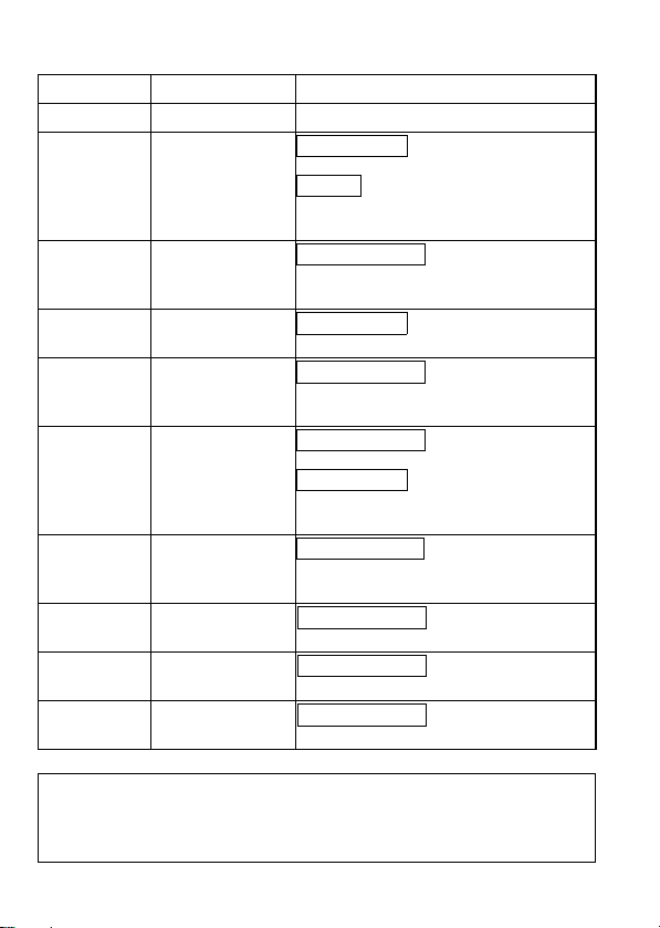
REVISIONS
* The manual number is noted at the lower right of the top cover.
Print Date *Manual Number Revision
Mar., 2006 IB(NA)-0800351-A First edition
Sep., 2006 IB(NA)-0800351-B Partial additon
Jul., 2007 IB(NA)-080351-C Partial corrections
Jan., 2009 IB(NA)-0800351-D Partial addition
Jun., 2009 IB(NA)-0800351-E Partial corrections
Jun., 2011 IB(NA)-0800351-F Partial corrections
Oct., 2014 IB(NA)-0800351-G Partial corrections
May, 2015 IB(NA)-0800351-H Partial corrections
Oct., 2016 IB(NA)-0800351-I Partial corrections
Apr., 2017 IB(NA)-0800351-J Partial corrections
Chapter 1
Addition
Compliance with the EMC and Low
Voltage Directives
Compliance with the EMC and Low
Voltage Directive,Chapter 2, 4, 5
Chapter 1, 2, 4, 5
Compliance with the EMC and Low
Voltage Directives
Chapter 4
Partial addition
Compliance with the Radio Waves Act
(South Korea)
SAFETY PRECAUTIONS
Chapter 4, 5
Cover
Compliance with the RoHS
Cover
This manual confers no industrial property rights or any rights of any other kind,
nor does it confer any patent licenses. Mitsubishi Electric Corporation cannot be
held responsible for any problems involving industrial property rights which may
occur as a result of using the contents noted in this manual.
© 2006 MITSUBISHI ELECTRIC CORPORATION
A-7

CONTENTS
1. OVERVIEW .................................................................................................... 1
2. SPECIFICATIONS ......................................................................................... 2
2.1 Performance Specifications ..................................................................... 2
2.2 Specifications of terminal block socket .................................................... 4
3. I/O SIGNALS AND REMOTE REGISTER ASSIGNMENT ............................ 5
3.1 I/O Signals Transferred to/from the Master Module ................................ 5
3.2 Remote Register Assignment .................................................................. 7
4. PART NAMES AND EXTERNAL DIMENSIONS ........................................... 8
5. INSTALLATION PROCEDURE ................................................................... 11
5.1 CC-Link communication unit installation ................................................ 11
5.2 Terminal block socket installation ............................... 13
6. WIRING METHOD ....................................................................................... 14
A-8
 Loading...