

Mitsubishi GOT1000 GT15, GOT1000, GT15 User Manual

U
GT15 User
,
s Manual
GT15 User,s Manual

A - 1
SAFETY PRECAUTIONS
(Always read these precautions before using this equipment.)
Before using this product, please read this manual and the relevant manuals introduced in this manual
carefully and pay full attention to safety to handle the product correctly.
The precautions given in this manual are concerned with this product.
In this manual, the safety precautions are ranked as "DANGER" and "CAUTION".
Note that the caution level may lead to a serious accident according to the circumstances. Always follow
the instructions of both levels because they are important to personal safety.
Please save this manual to make it accessible when required and always forward it to the end user.
[DESIGN PRECAUTIONS]
DANGER
Some failures of the GOT, communication unit or cable may keep the outputs on or off.
An external monitoring circuit should be provided to check for output signals which may lead to a
serious accident.
Not doing so can cause an accident due to false output or malfunction.
If a communication fault (including cable disconnection) occurs during monitoring on the GOT,
communication between the GOT and PLC CPU is suspended and the GOT becomes inoperative.
For bus connection: The CPU becomes faulty and the GOT becomes inoperative.
For other than bus connection: The GOT becomes inoperative.
A system where the GOT is used should be configured to perform any significant operation to the
system by using the switches of a device other than the GOT on the assumption that a GOT
communication fault will occur.
Not doing so can cause an accident due to false output or malfunction.
Do not use the GOT as the warning device that may cause a serious accident.
An independent and redundant hardware or mechanical interlock is required to configure the device
that displays and outputs serious warning.
Failure to observe this instruction may result in an accident due to incorrect output or malfunction.
DANGER
Indicates that incorrect handling may cause hazardous
conditions, resulting in death or severe injury.
CAUTION
Indicates that incorrect handling may cause hazardous
conditions, resulting in medium or slight personal injury or
physical damage.
A - 2
[DESIGN PRECAUTIONS]
[MOUNTING PRECAUTIONS]
DANGER
Incorrect operation of the touch switch(s) may lead to a serious accident if the GOT backlight is gone out.
When the GOT backlight goes out, the POWER LED flickers (green/orange) and the display section
turns black and causes the monitor screen to appear blank, while the input of the touch switch(s)
remains active.
This may confuse an operator in thinking that the GOT is in "screensaver" mode, who then tries to release
the GOT from this mode by touching the display section, which may cause a touch switch to operate.
Note that the following occurs on the GOT when the backlight goes out.
•The POWER LED flickers (green/orange) and the monitor screen appears blank
The display section of the GT1595-X is an analog-resistive type touch panel.
If you touch the display section simultaneously in 2 points or more, the switch that is located around
the center of the touched point, if any, may operate.
Do not touch the display section in 2 points or more simultaneously.
Doing so may cause an accident due to incorrect output or malfunction.
CAUTION
Do not bundle the control and communication cables with main-circuit, power or other wiring.
Run the above cables separately from such wiring and keep them a minimum of 100mm (3.94in.)
apart.Not doing so noise can cause a malfunction.
Do not press the GOT display section with a pointed material as a pen or driver.
Doing so can result in a damage or failure of the display section.
DANGER
Be sure to shut off all phases of the external power supply used by the system before mounting or
removing the GOT main unit to/from the panel.
Not doing so can cause the unit to fail or malfunction.
Be sure to shut off all phases of the external power supply used by the system before mounting or
removing the communication unit, option function board or multi-color display board onto/from the GOT.
Not doing so can cause the unit to fail or malfunction.
When installing the multi-color display board, wear an earth band etc. to avoid the static
electricity.Not doing so can cause a unit corruption.
CAUTION
Use the GOT in the environment that satisfies the general specifications described in this manual.
Not doing so can cause an electric shock, fire, malfunction or product damage or deterioration.
When mounting the GOT to the control panel, tighten the mounting screws in the specified torque range.
Undertightening can cause the GOT to drop, short circuit or malfunction.
Overtightening can cause a drop, short circuit or malfunction due to the damage of the screws or the GOT.
A - 3
[MOUNTING PRECAUTIONS]
[WIRING PRECAUTIONS]
CAUTION
When loading the communication unit to the GOT, fit it to the connection interface of the GOT and
tighten the mounting screws in the specified torque range.
Undertightening can cause the GOT to drop, short circuit or malfunction.
Overtightening can cause a drop, failure or malfunction due to the damage of the screws or unit.
When mounting the multi-color display board onto the GOT, tighten the mounting screws within the
specified torque range.
Loose tightening may cause the unit and/or GOT to malfunction due to poor contact.
Overtightening may damage the screws, unit and/or GOT; they might malfunction.
Push the option function board onto the corresponding connector until it clicks, so that it will be
secured firmly.
Push the multi-color display board onto the corresponding connector so that it will be secured firmly.
When inserting a CF card into the GOT, push it into the insertion slot until the CF card eject button
will pop out.
Failure to do so may cause a malfunction due to poor contact.
When inserting/removing a CF card into/from the GOT, turn the CF card access switch off in
advance.
Failure to do so may corrupt data within the CF card.
When removing a CF card from the GOT, make sure to support the CF card by hand, as it may pop
out.
Failure to do so may cause the CF card to drop from the GOT and break.
DANGER
Be sure to shut off all phases of the external power supply used by the system before wiring.
Failure to do so may result in an electric shock, product damage or malfunctions.
A - 4
[WIRING PRECAUTIONS]
[TEST OPERATION PRECAUTIONS]
CAUTION
Please make sure to ground FG terminal and LG terminal of the GOT power supply section by applying
Class D Grounding (Class 3 Grounding Method) or higher which is used exclusively for the GOT.
Not doing so may cause an electric shock or malfunction.
Terminal screws which are not to be used must be tightened always at torque 0.5 to 0.8 N
·m.
Otherwise there will be a danger of short circuit against the solderless terminals.
Use applicable solderless terminals and tighten them with the specified torque.
If any solderless spade terminal is used, it may be disconnected when the terminal screw comes
loose, resulting in failure.
Correctly wire the GOT power supply section after confirming the rated voltage and terminal
arrangement of the product.
Not doing so can cause a fire or failure.
Tighten the terminal screws of the GOT power supply section in the specified torque range.
Undertightening can cause a short circuit or malfunction.
Overtightening can cause a short circuit or malfunction due to the damage of the screws or the GOT.
Exercise care to avoid foreign matter such as chips and wire offcuts entering the GOT. Not doing so
can cause a fire, failure or malfunction.
The module has an ingress prevention label on its top to prevent foreign matter, such as wire offcuts,
from entering the module during wiring.
Do not peel this label during wiring.
Before starting system operation, be sure to peel this label because of heat dissipation.
Plug the bus connection cable by inserting it into the connector of the connected unit until it "clicks".
After plugging, check that it has been inserted snugly.
Not doing so can cause a malfunction due to a contact fault.
Plug the communication cable into the connector of the connected unit and tighten the mounting and
terminal screws in the specified torque range.
Undertightening can cause a short circuit or malfunction.
Overtightening can cause a short circuit or malfunction due to the damage of the screws or unit.
DANGER
Before performing the test operations of the user creation monitor screen (such as turning ON or
OFF bit device, changing the word device current value, changing the settings or current values of
the timer or counter, and changing the buffer memory current value), read through the manual
carefully and make yourself familiar with the operation method.
During test operation, never change the data of the devices which are used to perform significant
operation for the system.
False output or malfunction can cause an accident.
A - 5
[STARTUP/MAINTENANCE PRECAUTIONS]
[BACKLIGHT REPLACEMENT PRECAUTIONS]
DANGER
When power is on, do not touch the terminals.
Doing so can cause an electric shock or malfunction.
Connect the battery correctly.
Do not discharge, disassemble, heat, short, solder or throw the battery into the fire.
Incorrect handling may cause the battery to generate heat, burst or take fire, resulting in injuries or
fires
Before starting cleaning or terminal screw retightening, always switch off the power externally in all
phases.
Not switching the power off in all phases can cause a unit failure or malfunction.
Undertightening can cause a short circuit or malfunction.
Overtightening can cause a short circuit or malfunction due to the damage of the screws or unit.
CAUTION
Do not disassemble or modify the unit.
Doing so can cause a failure, malfunction, injury or fire.
Do not touch the conductive and electronic parts of the unit directly.
Doing so can cause a unit malfunction or failure.
The cables connected to the unit must be run in ducts or clamped.
Not doing so can cause the unit or cable to be damaged due to the dangling, motion or accidental
pulling of the cables or can cause a malfunction due to a cable connection fault.
When unplugging the cable connected to the unit, do not hold and pull the cable portion.
Doing so can cause the unit or cable to be damaged or can cause a malfunction due to a cable
connection fault.
Do not drop the module or subject it to strong shock.
A module damage may result.
Do not drop or give an impact to the battery mounted to the unit.
Doing so may damage the battery, causing the battery fluid to leak inside the battery.
If the battery is dropped or given an impact, dispose of it without using.
Before touching the unit, always touch grounded metal, etc. to discharge static electricity from
human body, etc.
Not doing so can cause the unit to fail or malfunction.
DANGER
Be sure to shut off all phases of the external power supply of the GOT (and the PLC CPU in the case
of a bus topology) and remove the GOT from the control panel before replacing the backlight (when
using the GOT with the backlight replaceable by the user).
Not doing so can cause an electric shock.
Replacing a backlight without removing the GOT from the control panel can cause the backlight or
control panel to drop, resulting in an injury.
A - 6
[BACKLIGHT REPLACEMENT PRECAUTIONS]
[DISPOSAL PRECAUTIONS]
[TRANSPORTATION PRECAUTIONS]
CAUTION
Wear gloves for the backlight replacement when using the GOT with the backlight replaceable by the
user.
Not doing so can cause an injury.
Before replacing a backlight, allow 5 minutes or more after turning off the GOT when using the GOT
with the backlight replaceable by the user.
Not doing so can cause a burn from heat of the backlight.
CAUTION
When disposing of the product, handle it as industrial waste.
CAUTION
When transporting lithium batteries, make sure to treat them based on the transport regulations.
(Refer to Appendix 3 for details of the regurated units.)
Make sure to transport the GOT main unit and/or relevant unit(s) in the manner they will not be
exposed to the impact exceeding the impact resistance described in the general specifications of this
manual, as they are precision devices.
Failure to do so may cause the unit to fail.
Check if the unit operates correctly after transportation.
A - 7
REVISIONS
The manual number is given on the bottom left of the back cover.
Japanese Manual Version SH-080507-F
© 2004 MITSUBISHI ELECTRIC CORPORATION
Print Date Manual Number Revision
Oct., 2004 SH(NA)-080528ENG-A First edition
Mar., 2005 SH(NA)-080528ENG-B Compatible with GT Designer2 Version2.09K
Chapter 6, Section 7.3.2, 8.2 to 8.6 8.2 to 8.4, 8.4.3, Section 9.1 to 9.3
9.1 to 9.2, Section 10.1 to 10.6 10.1 to 10.5, Section 12.1 to 12.6 12.1 to
12.5, Section 13.1, 13.2 to 13.6 13.3 to 13.7, Section 14.1 to 14.2 14.1,
Section 15.1 to 15.2 15.1, Section 16.1 to 16.2 16.1, Chapter 18, Section
18.6 18.3, 18.3 to 18.5 18.4 to 18.6, Section 19.1, 19.2
SAFETY PRECAUTIONS, Section 2.1, 2.2.2, Section 3.2, Section 4.1, 4.2, 4.3,
Section 5.3, Section 7.3.1, 7.5.1, 7.5.2, Section 8.3, Appendix 1, 2, 4
Section 10.6, Section 12.6, Section 13.2
Apr., 2005 SH(NA)-080528ENG-C
Section 4.1, 4.2, 4.3, 7.1.2, 7.5.2, 18.6, Appendix 1, Chapter 5 to 19 6 to 20,
Appendix 2 to 4 3 to 5
Chapter 5, Appendix 2
Sep., 2005 SH(NA)-080528ENG-D Compatible with GT Designer2 Version 2.18U
Chapter 1, Section 1.1, 1.2, Section 2.1, 2.2, 2.2.1, 2.2.2, Section 4.1 to 4.4,
Section 5.1, 5.1.3, 5.2.5, 5.4.2, Section 6.3, Section 7, 7.4, Section 8.1, 8.1.1,
8.1.2, 8.2, 8.3, 8.5.1, 8.5.2, 8.6.2, 8.7.3, 8.7.4, 8.11, 8.11.1, Section 9, 9.1, 9.2,
9.3.1, to 9.3.3, Section 10, 10.1.2 to 10.1.4, 10.2.2, 10.2.3, Chapter 11, 11.1,
11.1.1 to 11.1.3, 11.2.2, 11.2.3, 11.3.1, 11.3.2, 11.4.2, 11.5.1 to 11.5.3, Section
12.1.1 to 12.1.3, Section 13, 13.1.2, 13.1.3, 13.2.1, 13.2.2, 13.2.4, 13.3.2 to
13.3.4, 13.4.2, 13.5.2, 13.6.1 to 13.6.3, 13.7, 13.7.1, 13.7.2, 13.7.4, 13.7.5,
Chapter 14, 14.1.2, 14.2.1, 14.3.1 to 14.3.3, 14.4.2, 14.5.2, 14.6.2, 14.7.1,
14.7.2, Section 15.1.2, Section 16.1.3, Section 17.1.3, Chapter 18, 18.1, 18.2,
18.3, 18.3.1, 18.3.2, 18.4, Section 20.1, 20.2, Appendix 5
Section 5.3.2, 5.3.3, Section 6.2, 6.5, Section 8.4.1, 8.7.2, 8.8.1, 8.10.1, 8.10.2,
Section 10.2.1, Section 11.2.1, 11.3.3, Section 13.1.5, Section 14.1.1, Section
19.2, 19.4, 19.5, 19.6.1, 19.6.2, Appendix 1, 3
Section 3.2.1 to 3.2.4, 3.3.1, 3.3.2, Section 4.1, Section 8.5.3, Section 11.6,
11.8, Section 13.8, 13.9, 13.10, Section 18.5
Section 4.1 to 4.3 Section 4.2 to 4.4
Section 11.6 Section 11.7
This manual confers no industrial property rights or any rights of any other kind, nor does it confer any patent licenses.
Mitsubishi Electric Corporation cannot be held responsible for any problems involving industrial property rights which may
occur as a result of using the contents noted in this manual.
Partial corrections
Partial additions
Additions
Partial corrections
Additions
Partial corrections
Partial corrections
Additions

A - 8
SAFETY PRECAUTIONS . . . . . . . . . . . . . . . . . . . . . . . . . . . . . . . . . . . . . . . . . . . . . . . . . . . . . . . . . . . . A - 1
REVISIONS . . . . . . . . . . . . . . . . . . . . . . . . . . . . . . . . . . . . . . . . . . . . . . . . . . . . . . . . . . . . . . . . . . . . . . . A - 7
INTRODUCTION . . . . . . . . . . . . . . . . . . . . . . . . . . . . . . . . . . . . . . . . . . . . . . . . . . . . . . . . . . . . . . . . . . . A - 8
CONTENTS . . . . . . . . . . . . . . . . . . . . . . . . . . . . . . . . . . . . . . . . . . . . . . . . . . . . . . . . . . . . . . . . . . . . . . . A - 8
ABOUT MANUALS . . . . . . . . . . . . . . . . . . . . . . . . . . . . . . . . . . . . . . . . . . . . . . . . . . . . . . . . . . . . . . . . A - 16
ABBREVIATIONS AND GENERIC TERMS . . . . . . . . . . . . . . . . . . . . . . . . . . . . . . . . . . . . . . . . . . . . . A - 17
HOW TO READ THIS MANUAL . . . . . . . . . . . . . . . . . . . . . . . . . . . . . . . . . . . . . . . . . . . . . . . . . . . . . . A - 20
PACKING LIST . . . . . . . . . . . . . . . . . . . . . . . . . . . . . . . . . . . . . . . . . . . . . . . . . . . . . . . . . . . . . . . . . . . A - 21
1. OVERVIEW 1 - 1 to 1 - 5
1.1 Features 1 - 4
1.2 Rough Pre-operation Procedure 1 - 5
2. SYSTEM CONFIGURATION 2 - 1 to 2 - 10
2.1 Overall Configuration 2 - 1
2.2 Component List 2 - 2
2.2.1 GOT . . . . . . . . . . . . . . . . . . . . . . . . . . . . . . . . . . . . . . . . . . . . . . . . . . . . . . . . . . . . . . . . . . . 2 - 3
2.2.2 Option . . . . . . . . . . . . . . . . . . . . . . . . . . . . . . . . . . . . . . . . . . . . . . . . . . . . . . . . . . . . . . . . . 2 - 4
3. SPECIFICATIONS 3 - 1 to 3 - 11
3.1 General Specifications 3 - 1
3.2 Performance Specifications 3 - 2
3.2.1 GT1595-X . . . . . . . . . . . . . . . . . . . . . . . . . . . . . . . . . . . . . . . . . . . . . . . . . . . . . . . . . . . . . . 3 - 2
3.2.2 GT1585-S . . . . . . . . . . . . . . . . . . . . . . . . . . . . . . . . . . . . . . . . . . . . . . . . . . . . . . . . . . . . . . 3 - 4
3.2.3 GT1575-S, GT1575-V, GT1575-VN, GT1572-VN . . . . . . . . . . . . . . . . . . . . . . . . . . . . . . . . 3 - 6
3.2.4 GT1565-V, GT1562-VN . . . . . . . . . . . . . . . . . . . . . . . . . . . . . . . . . . . . . . . . . . . . . . . . . . . . 3 - 8
3.3 Power Supply Specifications 3 - 10
3.3.1 For GOTs powered from the 100 to 240VAC power supply . . . . . . . . . . . . . . . . . . . . . . . 3 - 10
3.3.2 For GOTs powered from the 24VDC power supply . . . . . . . . . . . . . . . . . . . . . . . . . . . . . . 3 - 11
4. PART NAME AND SETTINGS 4 - 1 to 4 - 8
4.1 Part Names and Settings of the GT1595 4 - 1
4.2 Part Names and Settings of the GT1585 4 - 3
INTRODUCTION
Thank you for choosing the Mitsubishi Graphic Operation Terminal.
Before using the equipment, please read this manual carefully to use the equipment to its optimum.
CONTENTS

A - 9
4.3 Part Names and Settings of the GT157 4 - 5
4.4 Part Names and Settings of the GT156 4 - 7
5. EMC AND LOW VOLTAGE DIRECTIVE 5 - 1 to 5 - 16
5.1 Requirements to Meet EMC Directive 5 - 1
5.1.1 EMC directive . . . . . . . . . . . . . . . . . . . . . . . . . . . . . . . . . . . . . . . . . . . . . . . . . . . . . . . . . . . . 5 - 2
5.1.2 Control panel . . . . . . . . . . . . . . . . . . . . . . . . . . . . . . . . . . . . . . . . . . . . . . . . . . . . . . . . . . . . 5 - 4
5.1.3 Noise filter (power supply line filter) . . . . . . . . . . . . . . . . . . . . . . . . . . . . . . . . . . . . . . . . . . . 5 - 5
5.2 Requirements for Conpliance with the Low Voltage Directive 5 - 6
5.2.1 Standard subject to GOT . . . . . . . . . . . . . . . . . . . . . . . . . . . . . . . . . . . . . . . . . . . . . . . . . . . 5 - 6
5.2.2 Power supply . . . . . . . . . . . . . . . . . . . . . . . . . . . . . . . . . . . . . . . . . . . . . . . . . . . . . . . . . . . . 5 - 6
5.2.3 Control panel . . . . . . . . . . . . . . . . . . . . . . . . . . . . . . . . . . . . . . . . . . . . . . . . . . . . . . . . . . . . 5 - 7
5.2.4 Grounding. . . . . . . . . . . . . . . . . . . . . . . . . . . . . . . . . . . . . . . . . . . . . . . . . . . . . . . . . . . . . . . 5 - 7
5.2.5 External wiring . . . . . . . . . . . . . . . . . . . . . . . . . . . . . . . . . . . . . . . . . . . . . . . . . . . . . . . . . . . 5 - 8
5.3 EMC Directive-Compliant System Configuration 5 - 9
5.3.1 GOT . . . . . . . . . . . . . . . . . . . . . . . . . . . . . . . . . . . . . . . . . . . . . . . . . . . . . . . . . . . . . . . . . . . 5 - 9
5.3.2 Connection method . . . . . . . . . . . . . . . . . . . . . . . . . . . . . . . . . . . . . . . . . . . . . . . . . . . . . . . 5 - 9
5.3.3 When the communication unit is used . . . . . . . . . . . . . . . . . . . . . . . . . . . . . . . . . . . . . . . . 5 - 10
5.3.4 Cables . . . . . . . . . . . . . . . . . . . . . . . . . . . . . . . . . . . . . . . . . . . . . . . . . . . . . . . . . . . . . . . . 5 - 10
5.4 Precautions for Wiring/Connecting the EMC Directive-Compliant Product 5 - 11
5.4.1 Power and ground wires wiring method . . . . . . . . . . . . . . . . . . . . . . . . . . . . . . . . . . . . . . . 5 - 11
5.4.2 Processing connection cables . . . . . . . . . . . . . . . . . . . . . . . . . . . . . . . . . . . . . . . . . . . . . . 5 - 12
5.4.3 Grounding the cable . . . . . . . . . . . . . . . . . . . . . . . . . . . . . . . . . . . . . . . . . . . . . . . . . . . . . . 5 - 16
6. INSTALLATION 6 - 1 to 6 - 4
6.1 Control Panel Inside Dimensions for Mounting GOT 6 - 1
6.2 Panel Cutting Dimensions 6 - 1
6.3 Mounting Position 6 - 2
6.4 Control Panel Inside Temperature and Mounting Angle 6 - 3
6.5 Installation Procedure 6 - 3
7. WIRING 7 - 1 to 7 - 6
7.1 Power Supply Wiring 7 - 2
7.2 Wiring of Connection Cables 7 - 3
7.3 Grouding 7 - 4
7.4 Power Supply Connection 7 - 6
8. OPTION 8 - 1 to 8 - 27
8.1 CF Card 8 - 1
8.1.1 Applicable CF card . . . . . . . . . . . . . . . . . . . . . . . . . . . . . . . . . . . . . . . . . . . . . . . . . . . . . . . . 8 - 1
8.1.2 Installing and removing procedures of the CF card . . . . . . . . . . . . . . . . . . . . . . . . . . . . . . . 8 - 2
8.2 Memory Card Adaptor 8 - 5

A - 10
8.2.1 Applicable memory card adaptor . . . . . . . . . . . . . . . . . . . . . . . . . . . . . . . . . . . . . . . . . . . . . 8 - 5
8.2.2 Installing procedure of the CF card into a memory card adaptor. . . . . . . . . . . . . . . . . . . . . 8 - 5
8.3 Option Function Board 8 - 6
8.3.1 Applicable option function board . . . . . . . . . . . . . . . . . . . . . . . . . . . . . . . . . . . . . . . . . . . . . 8 - 6
8.3.2 Installing procedure of the option function board. . . . . . . . . . . . . . . . . . . . . . . . . . . . . . . . . 8 - 6
8.4 Multi-Color Display Board 8 - 7
8.4.1 Applicable multi-color display board . . . . . . . . . . . . . . . . . . . . . . . . . . . . . . . . . . . . . . . . . . 8 - 7
8.4.2 Installing procedure of the multi-color display board . . . . . . . . . . . . . . . . . . . . . . . . . . . . . . 8 - 7
8.5 Communication Unit 8 - 8
8.5.1 Applicable communication unit . . . . . . . . . . . . . . . . . . . . . . . . . . . . . . . . . . . . . . . . . . . . . . 8 - 8
8.5.2 Installing procedure . . . . . . . . . . . . . . . . . . . . . . . . . . . . . . . . . . . . . . . . . . . . . . . . . . . . . . . 8 - 9
8.5.3 Installing multiple communication units in layers . . . . . . . . . . . . . . . . . . . . . . . . . . . . . . . . 8 - 18
8.6 RS-422 Conversion Unit 8 - 20
8.6.1 Applicable RS-422 conversion unit . . . . . . . . . . . . . . . . . . . . . . . . . . . . . . . . . . . . . . . . . . 8 - 20
8.6.2 Installing procedure . . . . . . . . . . . . . . . . . . . . . . . . . . . . . . . . . . . . . . . . . . . . . . . . . . . . . . 8 - 20
8.7 Battery 8 - 21
8.7.1 Applicable battery . . . . . . . . . . . . . . . . . . . . . . . . . . . . . . . . . . . . . . . . . . . . . . . . . . . . . . . 8 - 21
8.7.2 Battery specifications. . . . . . . . . . . . . . . . . . . . . . . . . . . . . . . . . . . . . . . . . . . . . . . . . . . . . 8 - 21
8.7.3 Battery replacement procedure . . . . . . . . . . . . . . . . . . . . . . . . . . . . . . . . . . . . . . . . . . . . . 8 - 21
8.7.4 Battery life . . . . . . . . . . . . . . . . . . . . . . . . . . . . . . . . . . . . . . . . . . . . . . . . . . . . . . . . . . . . . 8 - 22
8.8 Protective Sheet 8 - 23
8.8.1 Applicable protective sheet . . . . . . . . . . . . . . . . . . . . . . . . . . . . . . . . . . . . . . . . . . . . . . . . 8 - 23
8.8.2 Installing procedure . . . . . . . . . . . . . . . . . . . . . . . . . . . . . . . . . . . . . . . . . . . . . . . . . . . . . . 8 - 24
8.9 USB Environmental Protection Cover 8 - 25
8.9.1 Applicable USB environmental protecton cover . . . . . . . . . . . . . . . . . . . . . . . . . . . . . . . . 8 - 25
8.9.2 Installing procedure . . . . . . . . . . . . . . . . . . . . . . . . . . . . . . . . . . . . . . . . . . . . . . . . . . . . . . 8 - 25
8.10 Stand 8 - 26
8.10.1 Applicable stand . . . . . . . . . . . . . . . . . . . . . . . . . . . . . . . . . . . . . . . . . . . . . . . . . . . . . . . . 8 - 26
8.10.2 Installing procedure . . . . . . . . . . . . . . . . . . . . . . . . . . . . . . . . . . . . . . . . . . . . . . . . . . . . . . 8 - 26
8.11 Attachment 8 - 27
8.11.1 Applicable attachment . . . . . . . . . . . . . . . . . . . . . . . . . . . . . . . . . . . . . . . . . . . . . . . . . . . . 8 - 27
8.11.2 Installing procedure . . . . . . . . . . . . . . . . . . . . . . . . . . . . . . . . . . . . . . . . . . . . . . . . . . . . . . 8 - 27
9. UTILITY FUNCTION 9 - 1 to 9 - 11
9.1 Utility Execution 9 - 1
9.2 Utility Function List 9 - 2
9.3 Utility Display 9 - 5
9.3.1 Display operation of main menu . . . . . . . . . . . . . . . . . . . . . . . . . . . . . . . . . . . . . . . . . . . . . 9 - 6
9.3.2 Utility basic configuration . . . . . . . . . . . . . . . . . . . . . . . . . . . . . . . . . . . . . . . . . . . . . . . . . . . 9 - 9
9.3.3 Basic operation of settings change . . . . . . . . . . . . . . . . . . . . . . . . . . . . . . . . . . . . . . . . . . 9 - 10
10. COMMUNICATION INTERFACE SETTING (COMMUNICATION
SETTING) 10 - 1 to 10 - 17
10.1 Communication Setting 10 - 1
10.1.1 Communication setting functions. . . . . . . . . . . . . . . . . . . . . . . . . . . . . . . . . . . . . . . . . . . . 10 - 1

A - 11
10.1.2 Communication setting display operation. . . . . . . . . . . . . . . . . . . . . . . . . . . . . . . . . . . . . . 10 - 1
10.1.3 Communication setting contents . . . . . . . . . . . . . . . . . . . . . . . . . . . . . . . . . . . . . . . . . . . . 10 - 2
10.1.4 Communication setting display operation. . . . . . . . . . . . . . . . . . . . . . . . . . . . . . . . . . . . . . 10 - 7
10.2 Communication Detail Settings 10 - 12
10.2.1 Communication detail settings functions . . . . . . . . . . . . . . . . . . . . . . . . . . . . . . . . . . . . . 10 - 12
10.2.2 Communication detail settings display operation . . . . . . . . . . . . . . . . . . . . . . . . . . . . . . . 10 - 12
10.2.3 Display contents of communication detail settings . . . . . . . . . . . . . . . . . . . . . . . . . . . . . . 10 - 14
11. DISPLAY AND OPERATION SETTINGS (GOT SET UP) 11 - 1 to 11 - 29
11.1 Display Settings 11 - 2
11.1.1 Display setting functions. . . . . . . . . . . . . . . . . . . . . . . . . . . . . . . . . . . . . . . . . . . . . . . . . . . 11 - 2
11.1.2 Display operation of display setting . . . . . . . . . . . . . . . . . . . . . . . . . . . . . . . . . . . . . . . . . . 11 - 5
11.1.3 Display setting operations . . . . . . . . . . . . . . . . . . . . . . . . . . . . . . . . . . . . . . . . . . . . . . . . . 11 - 6
11.2 Brightness, Contrast Adjustment 11 - 11
11.2.1 Brightness adjustment function . . . . . . . . . . . . . . . . . . . . . . . . . . . . . . . . . . . . . . . . . . . . 11 - 11
11.2.2 Display operation of brightness, contrast . . . . . . . . . . . . . . . . . . . . . . . . . . . . . . . . . . . . . 11 - 11
11.2.3 Brightness adjustment operation . . . . . . . . . . . . . . . . . . . . . . . . . . . . . . . . . . . . . . . . . . . 11 - 12
11.3 Operation settings 11 - 13
11.3.1 Operation setting functions. . . . . . . . . . . . . . . . . . . . . . . . . . . . . . . . . . . . . . . . . . . . . . . .11 - 13
11.3.2 Display operation of display setting . . . . . . . . . . . . . . . . . . . . . . . . . . . . . . . . . . . . . . . . . 11 - 14
11.3.3 Setting operation of operation . . . . . . . . . . . . . . . . . . . . . . . . . . . . . . . . . . . . . . . . . . . . . 11 - 15
11.4 Security Level Change 11 - 17
11.4.1 Security level change functions . . . . . . . . . . . . . . . . . . . . . . . . . . . . . . . . . . . . . . . . . . . . 11 - 17
11.4.2 Security change display operation . . . . . . . . . . . . . . . . . . . . . . . . . . . . . . . . . . . . . . . . . . 11 - 17
11.4.3 Security level change operation . . . . . . . . . . . . . . . . . . . . . . . . . . . . . . . . . . . . . . . . . . . . 11 - 18
11.5 Utility call key setting 11 - 19
11.5.1 Utility call key setting function. . . . . . . . . . . . . . . . . . . . . . . . . . . . . . . . . . . . . . . . . . . . . . 11 - 19
11.5.2 Utility call key display operation . . . . . . . . . . . . . . . . . . . . . . . . . . . . . . . . . . . . . . . . . . . .11 - 19
11.5.3 Utility call key setting operation . . . . . . . . . . . . . . . . . . . . . . . . . . . . . . . . . . . . . . . . . . . .11 - 20
11.6 Adjusting the Touch Panel Position
(Touch panel calibration Setting) 11 - 22
11.6.1 Touch panel calibration setting function . . . . . . . . . . . . . . . . . . . 11 - 22
11.6.2 Touch panel calibration setting display operation. . . . . . . . . . . . . . . . . . . . . . . . . . . . . . . 11 - 22
11.6.3 Touch panel calibration operation . . . . . . . . . . . . . . . . . . . . . . . . . . . . . . . . . . . . . . . . . . 11 - 23
11.7 Q/QnA Ladder Monitor 11 - 25
11.7.1 Q/QnA ladder monitor setting function . . . . . . . . . . . . . . . . . . . . . . . . . . . . . . . . . . . . . . . 11 - 25
11.7.2 Display operation of display setting . . . . . . . . . . . . . . . . . . . . . . . . . . . . . . . . . . . . . . . . . 11 - 26
11.7.3 Q/QnA ladder monitor setting operation . . . . . . . . . . . . . . . . . . . . . . . . . . . . . . . . . . . . . . 11 - 27
11.8 Transparent Mode
(Transparent channel setting) 11 - 28
11.8.1 Transparent function setting function . . . . . . . . . . . . . . . . . . . . . . . . . . . . . . . . . . . . . . . . 11 - 28
11.8.2 Transparent function display operation . . . . . . . . . . . . . . . . . . . . . . . . . . . . . . . . . . . . . . 11 - 28
11.8.3 Setting operation of transparent function . . . . . . . . . . . . . . . . . . . . . . . . . . . . . . . . . . . . . 11 - 29
12. CLOCK SETTINGS AND BATTERY STATUS DISPLAY
(TIME SETTING AND DISPLAY) 12 - 1 to 12 -5

A - 12
12.1 Time Setting and Display 12 - 1
12.1.1 Time setting and display functions. . . . . . . . . . . . . . . . . . . . . . . . . . . . . . . . . . . . . . . . . . . 12 - 1
12.1.2 Display operation of clock display and setting . . . . . . . . . . . . . . . . . . . . . . . . . . . . . . . . . . 12 - 1
12.1.3 Clock setting operations . . . . . . . . . . . . . . . . . . . . . . . . . . . . . . . . . . . . . . . . . . . . . . . . . . 12 - 2
13. FILE DISPLAY AND COPY(PROGRAM/DATA CONTROL)
13 - 1 to 13 - 90
13.1 Data Storage Location 13 - 1
13.1.1 Drive name allocation . . . . . . . . . . . . . . . . . . . . . . . . . . . . . . . . . . . . . . . . . . . . . . . . . . . . 13 - 1
13.1.2 Data type and the storage location . . . . . . . . . . . . . . . . . . . . . . . . . . . . . . . . . . . . . . . . . . 13 - 2
13.1.3 OS version confirmation . . . . . . . . . . . . . . . . . . . . . . . . . . . . . . . . . . . . . . . . . . . . . . . . . . 13 - 4
13.1.4 Capacity confirmation of the project data downloading location . . . . . . . . . . . . . . . . . . . . 13 - 6
13.1.5 Display file . . . . . . . . . . . . . . . . . . . . . . . . . . . . . . . . . . . . . . . . . . . . . . . . . . . . . . . . . . . . . 13 - 7
13.2 OS Information 13 - 10
13.2.1 Function of OS information . . . . . . . . . . . . . . . . . . . . . . . . . . . . . . . . . . . . . . . . . . . . . . . 13 - 10
13.2.2 Display operation of OS information . . . . . . . . . . . . . . . . . . . . . . . . . . . . . . . . . . . . . . . . 13 - 10
13.2.3 Display example of OS information . . . . . . . . . . . . . . . . . . . . . . . . . . . . . . . . . . . . . . . . . 13 - 11
13.2.4 Operation of OS information . . . . . . . . . . . . . . . . . . . . . . . . . . . . . . . . . . . . . . . . . . . . . . 13 - 12
13.3 Project Information 13 - 17
13.3.1 Function of OS information . . . . . . . . . . . . . . . . . . . . . . . . . . . . . . . . . . . . . . . . . . . . . . . 13 - 17
13.3.2 Display operation of project information . . . . . . . . . . . . . . . . . . . . . . . . . . . . . . . . . . . . . 13 - 17
13.3.3 Display example of project information . . . . . . . . . . . . . . . . . . . . . . . . . . . . . . . . . . . . . . 13 - 18
13.3.4 Operation of project information . . . . . . . . . . . . . . . . . . . . . . . . . . . . . . . . . . . . . . . . . . . 13 - 19
13.4 Alarm Information 13 - 28
13.4.1 Function of alarm information . . . . . . . . . . . . . . . . . . . . . . . . . . . . . . . . . . . . . . . . . . . . . 13 - 28
13.4.2 The display operation of alarm information . . . . . . . . . . . . . . . . . . . . . . . . . . . . . . . . . . . 13 - 28
13.4.3 The display example of alarm information . . . . . . . . . . . . . . . . . . . . . . . . . . . . . . . . . . . . 13 - 29
13.4.4 Alarm information operation. . . . . . . . . . . . . . . . . . . . . . . . . . . . . . . . . . . . . . . . . . . . . . . 13 - 30
13.5 Hard Copy Information 13 - 36
13.5.1 The function of hardcopy information . . . . . . . . . . . . . . . . . . . . . . . . . . . . . . . . . . . . . . . 13 - 36
13.5.2 The display operation of hardcopy information . . . . . . . . . . . . . . . . . . . . . . . . . . . . . . . . 13 - 36
13.5.3 Display exmaple of hardcopy information . . . . . . . . . . . . . . . . . . . . . . . . . . . . . . . . . . . . 13 - 37
13.5.4 The operation of hardcopy information . . . . . . . . . . . . . . . . . . . . . . . . . . . . . . . . . . . . . . 13 - 38
13.6 Memory card format 13 - 41
13.6.1 Format function of memory card . . . . . . . . . . . . . . . . . . . . . . . . . . . . . . . . . . . . . . . . . . . 13 - 41
13.6.2 Display operation of memory card format . . . . . . . . . . . . . . . . . . . . . . . . . . . . . . . . . . . . 13 - 41
13.6.3 Format operation of memory card . . . . . . . . . . . . . . . . . . . . . . . . . . . . . . . . . . . . . . . . . . 13 - 42
13.7 Advanced Recipe Information 13 - 44
13.7.1 Function of advanced recipe information. . . . . . . . . . . . . . . . . . . . . . . . . . . . . . . . . . . . . 13 - 44
13.7.2 Operation of advanced recipe information display. . . . . . . . . . . . . . . . . . . . . . . . . . . . . . 13 - 45
13.7.3 Example of advanced recipe information display . . . . . . . . . . . . . . . . . . . . . . . . . . . . . . 13 - 46
13.7.4 Advanced recipe information operation . . . . . . . . . . . . . . . . . . . . . . . . . . . . . . . . . . . . . . 13 - 48
13.7.5 Precautions . . . . . . . . . . . . . . . . . . . . . . . . . . . . . . . . . . . . . . . . . . . . . . . . . . . . . . . . . . . 13 - 65
13.8 Logging Information 13 - 67
13.8.1 Function of logging information . . . . . . . . . . . . . . . . . . . . . . . . . . . . . . . . . . . . . . . . . . . . 13 - 67
13.8.2 Display operation of logging information . . . . . . . . . . . . . . . . . . . . . . . . . . . . . . . . . . . . . 13 - 68
13.8.3 Example of logging information display . . . . . . . . . . . . . . . . . . . . . . . . . . . . . . . . . . . . . . 13 - 69

A - 13
13.8.4 Logging information operation . . . . . . . . . . . . . . . . . . . . . . . . . . . . . . . . . . . . . . . . . . . . . 13 - 70
13.8.5 Precautions. . . . . . . . . . . . . . . . . . . . . . . . . . . . . . . . . . . . . . . . . . . . . . . . . . . . . . . . . . . . 13 - 79
13.9 Memory Information 13 - 81
13.9.1 Memory information functions . . . . . . . . . . . . . . . . . . . . . . . . . . . . . . . . . . . . . . . . . . . . . 13 - 81
13.9.2 Memory information display operation . . . . . . . . . . . . . . . . . . . . . . . . . . . . . . . . . . . . . . . 13 - 81
13.9.3 Memory information display example . . . . . . . . . . . . . . . . . . . . . . . . . . . . . . . . . . . . . . . . 13 - 82
13.10 Special Data Information 13 - 83
13.10.1 Special data information function . . . . . . . . . . . . . . . . . . . . . . . . . . . . . . . . . . . . . . . . . . . 13 - 83
13.10.2 Special data information display operation. . . . . . . . . . . . . . . . . . . . . . . . . . . . . . . . . . . . 13 - 83
13.10.3 Special data information display example . . . . . . . . . . . . . . . . . . . . . . . . . . . . . . . . . . . . 13 - 84
13.10.4 Special data information operation . . . . . . . . . . . . . . . . . . . . . . . . . . . . . . . . . . . . . . . . . . 13 - 85
14. GOT SELF CHECK (DEBUG & SELF CHECK) 14 - 1 to 14 - 19
14.1 Debug 14 - 1
14.1.1 The Debug function . . . . . . . . . . . . . . . . . . . . . . . . . . . . . . . . . . . . . . . . . . . . . . . . . . . . . . 14 - 1
14.1.2 Display operation of Debug . . . . . . . . . . . . . . . . . . . . . . . . . . . . . . . . . . . . . . . . . . . . . . . .14 - 2
14.2 Self check 14 - 3
14.2.1 Self check function . . . . . . . . . . . . . . . . . . . . . . . . . . . . . . . . . . . . . . . . . . . . . . . . . . . . . . . 14 - 3
14.3 Memory Check 14 - 4
14.3.1 Memory check function. . . . . . . . . . . . . . . . . . . . . . . . . . . . . . . . . . . . . . . . . . . . . . . . . . . . 14 - 4
14.3.2 Display operation of memory check . . . . . . . . . . . . . . . . . . . . . . . . . . . . . . . . . . . . . . . . . . 14 - 4
14.3.3 Memory check operation . . . . . . . . . . . . . . . . . . . . . . . . . . . . . . . . . . . . . . . . . . . . . . . . . .14 - 5
14.4 Drawing Check 14 - 7
14.4.1 Drawing check function . . . . . . . . . . . . . . . . . . . . . . . . . . . . . . . . . . . . . . . . . . . . . . . . . . . 14 - 7
14.4.2 Display operation of drawing check . . . . . . . . . . . . . . . . . . . . . . . . . . . . . . . . . . . . . . . . . . 14 - 7
14.4.3 Drawing check operation . . . . . . . . . . . . . . . . . . . . . . . . . . . . . . . . . . . . . . . . . . . . . . . . . .14 - 8
14.5 Font Check 14 - 12
14.5.1 Font check function . . . . . . . . . . . . . . . . . . . . . . . . . . . . . . . . . . . . . . . . . . . . . . . . . . . . . 14 - 12
14.5.2 Display operation of Font check . . . . . . . . . . . . . . . . . . . . . . . . . . . . . . . . . . . . . . . . . . . . 14 - 12
14.5.3 Font check operation . . . . . . . . . . . . . . . . . . . . . . . . . . . . . . . . . . . . . . . . . . . . . . . . . . . . 14 - 13
14.6 Touch Panel Check 14 - 14
14.6.1 Touch panel check function . . . . . . . . . . . . . . . . . . . . . . . . . . . . . . . . . . . . . . . . . . . . . . . 14 - 14
14.6.2 Display operation of Touch panel check. . . . . . . . . . . . . . . . . . . . . . . . . . . . . . . . . . . . . . 14 - 14
14.6.3 Touch panel check operations . . . . . . . . . . . . . . . . . . . . . . . . . . . . . . . . . . . . . . . . . . . . . 14 - 15
14.7 I/O Check 14 - 16
14.7.1 I/O check function. . . . . . . . . . . . . . . . . . . . . . . . . . . . . . . . . . . . . . . . . . . . . . . . . . . . . . . 14 - 16
14.7.2 Display operation of I/O Check. . . . . . . . . . . . . . . . . . . . . . . . . . . . . . . . . . . . . . . . . . . . . 14 - 16
14.7.3 I/O Check Operation. . . . . . . . . . . . . . . . . . . . . . . . . . . . . . . . . . . . . . . . . . . . . . . . . . . . . 14 - 17
15. CLEANING OF DISPLAY SECTION (CLEAN) 15 - 1 to 15 - 2
15.1 Clean 15 - 1
15.1.1 Display operation of Clean . . . . . . . . . . . . . . . . . . . . . . . . . . . . . . . . . . . . . . . . . . . . . . . . .15 - 1
15.1.2 Operation of Clean . . . . . . . . . . . . . . . . . . . . . . . . . . . . . . . . . . . . . . . . . . . . . . . . . . . . . . . 15 - 2

A - 14
16. MAINTENANCE TIME NOTIFICATION SETTING (MAINTENANCE
TIMING SETTING) 16 - 1 to 16 - 4
16.1 Maintenance Timing Setting 16 - 2
16.1.1 Maintenance time notification function. . . . . . . . . . . . . . . . . . . . . . . . . . . . . . . . . . . . . . . . 16 - 2
16.1.2 Display operation of maintenance timimg setting . . . . . . . . . . . . . . . . . . . . . . . . . . . . . . . 16 - 3
16.1.3 Operation of maintenance time notification . . . . . . . . . . . . . . . . . . . . . . . . . . . . . . . . . . . . 16 - 4
17. ADDITION TIMES RESET FOR MAINTENANCE TIME NOTIFICATION
(ADDITION TIMES RESET) 17 - 1 to 17 - 2
17.1 Addition times reset 17 - 1
17.1.1 Addition times reset function . . . . . . . . . . . . . . . . . . . . . . . . . . . . . . . . . . . . . . . . . . . . . . . 17 - 1
17.1.2 Display operation of Addition times reset . . . . . . . . . . . . . . . . . . . . . . . . . . . . . . . . . . . . . 17 - 1
17.1.3 Operation of Addition times reset . . . . . . . . . . . . . . . . . . . . . . . . . . . . . . . . . . . . . . . . . . . 17 - 2
18. INSTALLATION OF COREOS, BOOTOS AND STANDARD MONITOR OS
18 - 1 to 18 - 13
18.1 BootOS and Standard Monitor OS Required for installation 18 - 2
18.2 Prior Preparations for Installing BootOS and Standard Monitor OS 18 - 3
18.3 BootOS and Standard Monitor OS Installation Using Memory Card 18 - 4
18.3.1 Installing when starting the GOT . . . . . . . . . . . . . . . . . . . . . . . . . . . . . . . . . . . . . . . . . . . . 18 - 5
18.3.2 Installation method using the program/data control function (Utility) . . . . . . . . . . . . . . . . . 18 - 6
18.4 When installing the different version of BootOS, standard monitor OS 18 - 8
18.5 CoreOS 18 - 10
18.5.1 Installing the CoreOS. . . . . . . . . . . . . . . . . . . . . . . . . . . . . . . . . . . . . . . . . . . . . . . . . . . . 18 - 10
18.5.2 When the CoreOS cannot be installed . . . . . . . . . . . . . . . . . . . . . . . . . . . . . . . . . . . . . . 18 - 13
19. MAINTENANCE AND INSPECTION 19 - 1 to 19 - 16
19.1 Daily Inspection 19 - 2
19.2 Periodic Inspection 19 - 2
19.3 Cleaning Method 19 - 3
19.4 Battery Voltage Low Detection and Battery Replacement 19 - 4
19.5 Backlight Shutoff Detection and Replacement 19 - 5
19.6 Backlight Replacement 19 - 6
19.6.1 Applicable backlight . . . . . . . . . . . . . . . . . . . . . . . . . . . . . . . . . . . . . . . . . . . . . . . . . . . . . . 19 - 6
19.6.2 Replacement procedure of backlight . . . . . . . . . . . . . . . . . . . . . . . . . . . . . . . . . . . . . . . . . 19 - 6
20. ERROR MESSAGE AND SYSTEM ALARM 20 - 1 to 20 - 15
20.1 Error Contents Display 20 - 1
20.2 List of Error Message/System Alarm 20 - 3
20.3 Troubleshooting in Bus Connection 20 - 12

A - 15
20.3.1 Locating error positions . . . . . . . . . . . . . . . . . . . . . . . . . . . . . . . . . . . . . . . . . . . . . . . . . . 20 - 12
20.3.2 Further locating error positions. . . . . . . . . . . . . . . . . . . . . . . . . . . . . . . . . . . . . . . . . . . . . 20 - 13
20.3.3 Specific example of troubleshooting. . . . . . . . . . . . . . . . . . . . . . . . . . . . . . . . . . . . . . . . . 20 - 14
20.4 Troubleshooting for Monitoring 20 - 15
APPENDICES App- 1 to App - 22
Appendix 1 External Dimensions App- 1
Appendix 2 Confirming of GOT's Hardware Version App- 9
Appendix 3 Usage Condition of Utility Function App- 10
Appendix 4 Transportation Precautions App- 15
Appendix 4.1 Relevant models . . . . . . . . . . . . . . . . . . . . . . . . . . . . . . . . . . . . . . . . . . . . . . . . . . . App- 15
Appendix 4.2 Transportation guidelines . . . . . . . . . . . . . . . . . . . . . . . . . . . . . . . . . . . . . . . . . . . . App- 15
Appendix 5 List of Functions Added by GT Designer2 Version Upgrade (For GOT1000 Series) App- 16
INDEX Index- 1 to Index- 3
A - 16
ABOUT MANUALS
The following manuals are also related to this product.
In necessary, order them by quoting the details in the tables below.
*1 The manual in PDF-format is included in the GT Works2 and GT Designer2 products.
Related Manuals
Manual Name
Manual Number
(Model Code)
GT Designer2 Version2 Basic Operation/Data Transfer Manual (For GOT1000 Series)
Describes methods of the GT Designer2 installation operation, basic operation for drawing and transmitting data
to GOT1000 series
(Sold separately)
*1
SH-080529ENG
(1D7M24)
GT Designer2 Version2 Screen Design Manual (For GOT1000 Series) 1/2
GT Designer2 Version2 Screen Design Manual (For GOT1000 Series) 2/2
Describes specifications and settings of the object functions used in GOT1000 series
(Sold separately)
*1
SH-080530ENG
SH-080531ENG
(1D7M25)
GOT1000 Series Connection Manual (1/2, 2/2)
Describes system configurations of the connection method applicable to GOT1000 series and cable creation
method
(Sold separately)
*1
SH-080532ENG
(1D7M26)
GOT1000 Series Extended/Option Functions Manual
Describes extended functions and option functions applicable to GOT series.
(Sold separately)
*1
SH-080544ENG
(1D7M32)
GOT1000 Series Gateway Functions Manual
Describes specifications, system configurations and setting method of the gateway function.
(Sold separately)
*1
SH-080545ENG
(1D7M33)
A - 17
ABBREVIATIONS AND GENERIC TERMS
Abbreviations and generic terms used in this manual are as follows:
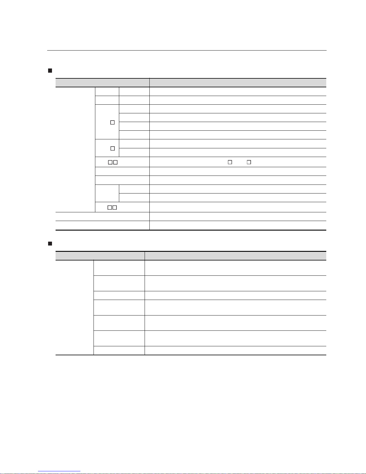
GOT
Communication unit
Abbreviations and generic terms Description
GOT1000 Series
GT1595 GT1595-X Abbreviation of GT1595-XTBA
GT1585 GT1585-S Abbreviation of GT1585-STBA, GT1585-STBD
GT1 57
GT1575-S Abbreviation of GT1575-STBA, GT1575-STBD
GT1575-V Abbreviation of GT1575-VTBA, GT1575-VTBD
GT1575-VN Abbreviation of GT1575-VNBA, GT1575-VNBD
GT1572-VN Abbreviation of GT1572-VNBA, GT1572-VNBD
GT1 56
GT1565-V Abbreviation of GT1565-VTBA, GT1565-VTBD
GT1562-VN Abbreviation of GT1562-VNBA, GT1562-VNBD
GT1 5 , GT15
Abbreviation of GT1595, GT1585, GT157 , GT156
GT1155-Q Abbreviation of GT1155-QSBD
GT1150-Q Abbreviation of GT1150-QLBD
Handy
GOT
GT1155HS-Q Abbreviation of GT1155HS-QSBD
GT1150HS-Q Abbreviation of GT1150HS-QLBD
GT11 , GT11
Abbreviation of GT1155-Q, GT1150-Q, GT11 Handy GOT
GOT900 Series Abbreviation of GOT-A900 series, GOT-F900 series
GOT800 Series
Abbreviation of GOT-800 series
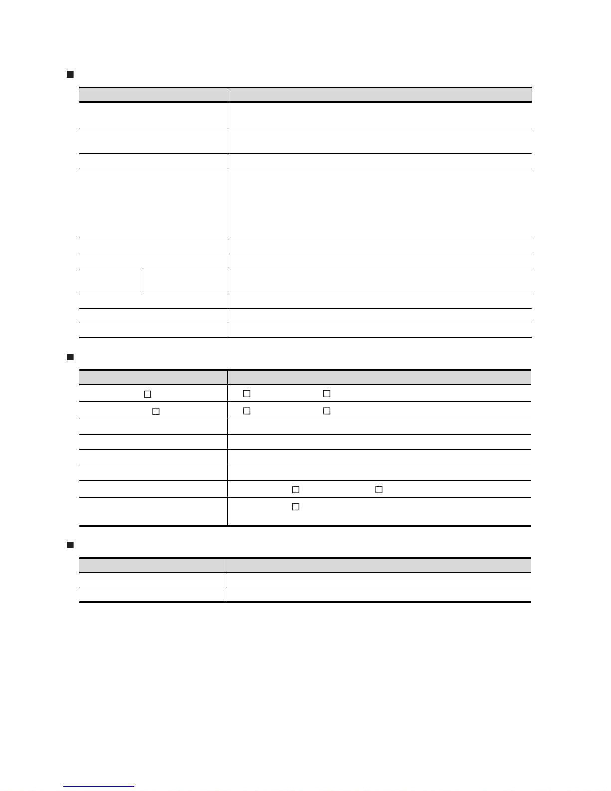
Abbreviations and generic terms Description
Communication
unit
Bus connection unit
GT15-QBUS, GT15-QBUS2, GT15-ABUS, GT15-ABUS2,
GT15-75QBUSL, GT15-75QBUS2L, GT15-75ABUSL, GT15-75ABUS2L
Serial communication
unit
GT15-RS2-9P, GT15-RS4-9S, GT15-RS4-TE
RS-422 conversion unit GT15-RS2T4-9P, GT15-RS2T4-25P
Ethernet communication
unit
GT15-J71E71-100
MELSECNET/10
communication unit
GT15-75J71LP23-Z, GT15-75J71BR13-Z
CC-Link communication
unit
GT15-75J61BT13-Z
Interface converter unit GT15-75IF900
A - 18
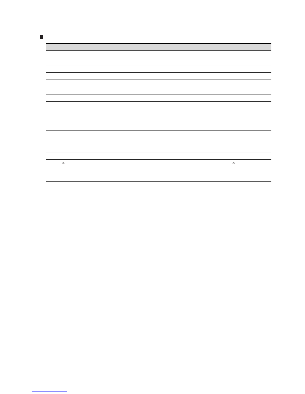
Option
Software
License (for GT SoftGOT2)
Abbreviations and generic terms Description
Backlight
GT15-90XLTT, GT15-80SLTT, GT15-70SLTT, GT15-70VLTT,
GT15-70VLTN, GT15-60VLTT, GT15-60VLTN
Option function board
GT1 5-FN B, GT 1 5-Q F NB, GT1 5-QF NB1 6 M, GT1 5-QF NB32 M,
GT15-QFNB48M, GT11-50FNB
Multi-color display board GT15-XHNB, GT15-VHNB
Protective Sheet
GT15-90PSCB, GT15-90PSGB, GT15-90PSCW, GT15-90PSGW,
GT15-80PSCB, GT15-80PSGB, GT15-80PSCW, GT15-80PSGW,
GT15-70PSCB, GT15-70PSGB, GT15-70PSCW, GT15-70PSGW,
GT15-60PSCB, GT15-60PSGB, GT15-60PSCW, GT15-60PSGW,
GT11-50PSCB, GT11-50PSGB, GT11-50PSCW, GT11-50PSGW,
GT11H-50PSC
USB environmental protection cover GT15-UCOV, GT11-50UCOV
Stand GT15-90STAND, GT15-80STAND, GT15-70STAND, A9GT-50STAND
Memory card CF card
GT05-MEM-16MC, GT05-MEM-32MC, GT05-MEM-64MC,
GT05-MEM-128MC, GT05-MEM-256MC
Memory card adaptor GT05-MEM-ADPC
Attachment GT15-60ATT-97, GT15-60ATT-96
Battery GT15-BAT, GT11-50BAT
Abbreviations and generic terms Description
GT W ork s 2 Vers i on
SW D5C-GTWK2-E, SW D5C-GTWK2-EV
GT Designer2 Version
SW D5C-GTD2-E, SW D5C-GTD2-EV
GT Designer2
Abbreviation of screen drawing software GT Designer2 for GOT1000/GOT900 series
GT Converter2
Abbreviation of data conversion software GT Converter2 for GOT1000/GOT900 series
GT S i mul a tor 2
Abbreviation of screen simulator GT Simulator 2 for GOT1000 / GOT900 series
GT SoftGOT2
Abbreviation of monitoring software GT SoftGOT2
GX Developer
Abbreviation of SW D5C-GPPW-E(-EV)/SW D5F-GPPW-E type software package
GX Simulator
Abbreviation of SW D5C-LLT-E(-EV) type ladder logic test tool function software packages
(SW5D5C-LLT (-EV) or later versions)
Abbreviations and generic terms Description
License A9GTSOFT-LKEY-P (For DOS/V PC)
License FD SW5D5F-SGLKEY-J (For PC CPU module)
A - 19
Others
Abbreviations and generic terms Description
Omron PLC Abbreviation of PLC manufactured by OMRON Corporation
KEYENCE PLC Abbreviation of PLC manufactured by KEYENCE
Sharp PLC Abbreviation of PLC manufactured by SHARP Corporation
Toshiba PLC Abbreviation of PLC manufactured by TOSHIBA CORPORATION
HITACHI PLC Abbreviation of PLC manufactured by Hitachi Industrial Equipment Systems Co., Ltd.
Matsushita PLC Abbreviation of PLC manufactured by Matsushita Electric Works, Ltd
Yaskawa PLC Abbreviation of PLC manufactured by YASKAWA Electric Corporation
Yokogawa PLC Abbreviation of PLC manufactured by Yokogawa Electric Corporation
Allen-Bradley PLC Abbreviation of PLC manufactured by Allen-Bradley
SIEMENS PLC Abbreviation of PLC manufactured by SIEMENS
OMRON temperature controller Abbreviation of temperature controller manufactured by OMRON
YAMATAKE temperature controller Abbreviation of temperature controller manufactured by YAMATAKE
RKC temperature controller Abbreviation of temperature controller manufactured by RKC
GOT (server) Abbreviation of GOTs that use the server function
GOT (client) Abbreviation of GOTs that use the client function
Windows font Abbreviation of TrueType font and OpenType font available for Windows
Intelligent function module
Indicates the modules other than the PLC CPU, power supply module and I/O module that are
mounted to the base unit.
A - 20
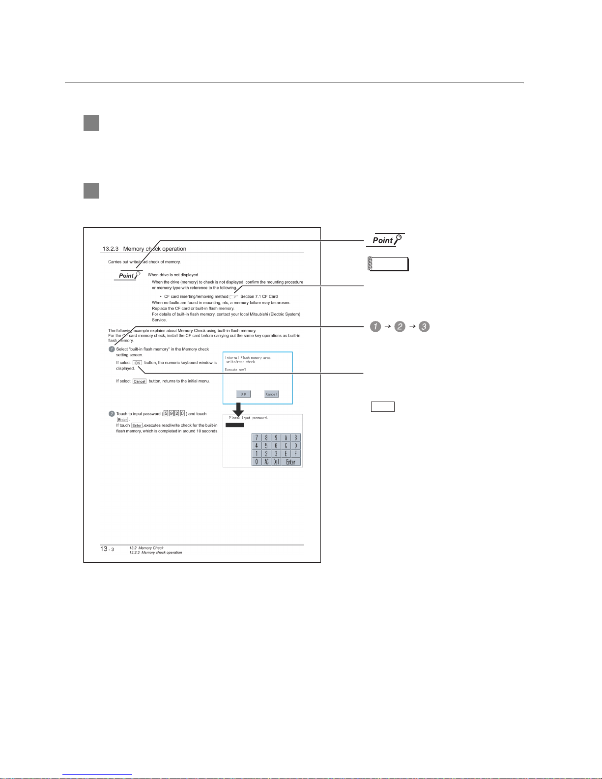
HOW TO READ THIS MANUAL
1 Functions
This manual describes functions available for the GT Designer2 Version2.18U.
For the added functions by the product version upgrade, refer to the list of functions added by GT
Desiger2 version upgrade in Appendices.
2 Symbols
Following symbols are used in this manual.
Refers to the information
required.
Refers to the supplementary
explanations for reference.
Indicates the operation steps.
Menu and items are differentiated with
parentheses.
: refers to the menu of GOT utility.
: refers to the button in the dialog
box of GOT utility.
Indicates the items in which the detailed
explanation is described (manual, chapter,
section, item of the manual).
. . . .
[ ]
Remark

A - 21
PACKING L IST
After unpacking, confirm that the following parts are included.
The following products are included a spare for the plastic fixing screw of the GOT.
• GT1585-S: Hardware Version B or earlier (Apr.,2005)
• GT1575-S: Hardware Version B or earlier (Apr.,2005)
• GT1575-V: Hardware Version D or earlier (Apr.,2005)
• GT1565-V: Hardware Version D or earlier (Apr.,2005)
Model Item Quantity
GT1595-X
GOT 1
Installation fitting 8
GT15 General Description 1
GT1585-S,
GT1575-S,
GT1575-V,
GT1575-VN,
GT1572-VN,
GT1565-V,
GT1562-VN
GOT 1
Installation fitting 4
GT15 General Description 1
1 - 1
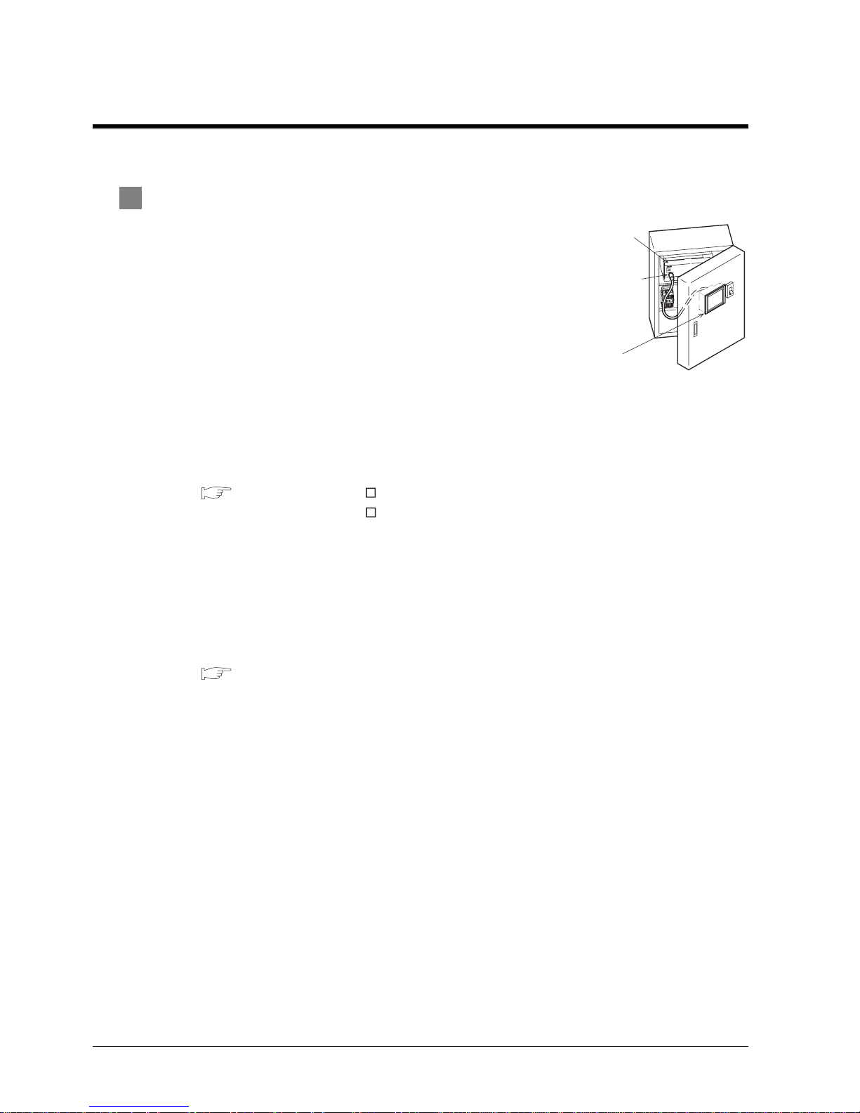
1. OVERVIEW
1 About GOT
GOT is installed on the panel surface of control panel or operating panel
and connects to the PLC in the control panel. GOT carries out switch
operation, lamp display, data display, and message display etc.
For display screen, two kinds of display screens, user screen and utility
screen are available.
(1) User screen
User screen is a screen drawn by GT Designer2.
The objects of "Touch switch", "Lamp display", "Comment display",
and "Numeric display" can be laid out arbitrarily to be displayed.
Moreover, the multiple screens created by GT Designer2 can be overlapped and switched to be
displayed.
For details, refer to the following.
GT Designer2 Version Basic Operation/Data Transfer Manual
GT Designer2 Version Screen Design Manual
(2) Utility Screen
Utility screen is a screen prepared beforehand for GOT.
Installing BootOS or standard OS in the GOT from GT Designer2 enables utility screen displaying.
The utility screen has menus as [Brightness/contrast adjustment screen] and [GOT memory check
screen] etc.
For details, refer to the following.
Chapter 9 to Chapter 17
PLC
C
onnector for
p
rogram
GOT

1 - 2
1
OVERVIEW
2
SYSTEM
CONFIGURATION
3
SPECIFICATIONS
4
PART NAME AND
SETTINGS
5
EMC AND LOW
VOLTAGE
DIRECTIVE
6
INSTALLATION
7
WIRING
8
OPTION
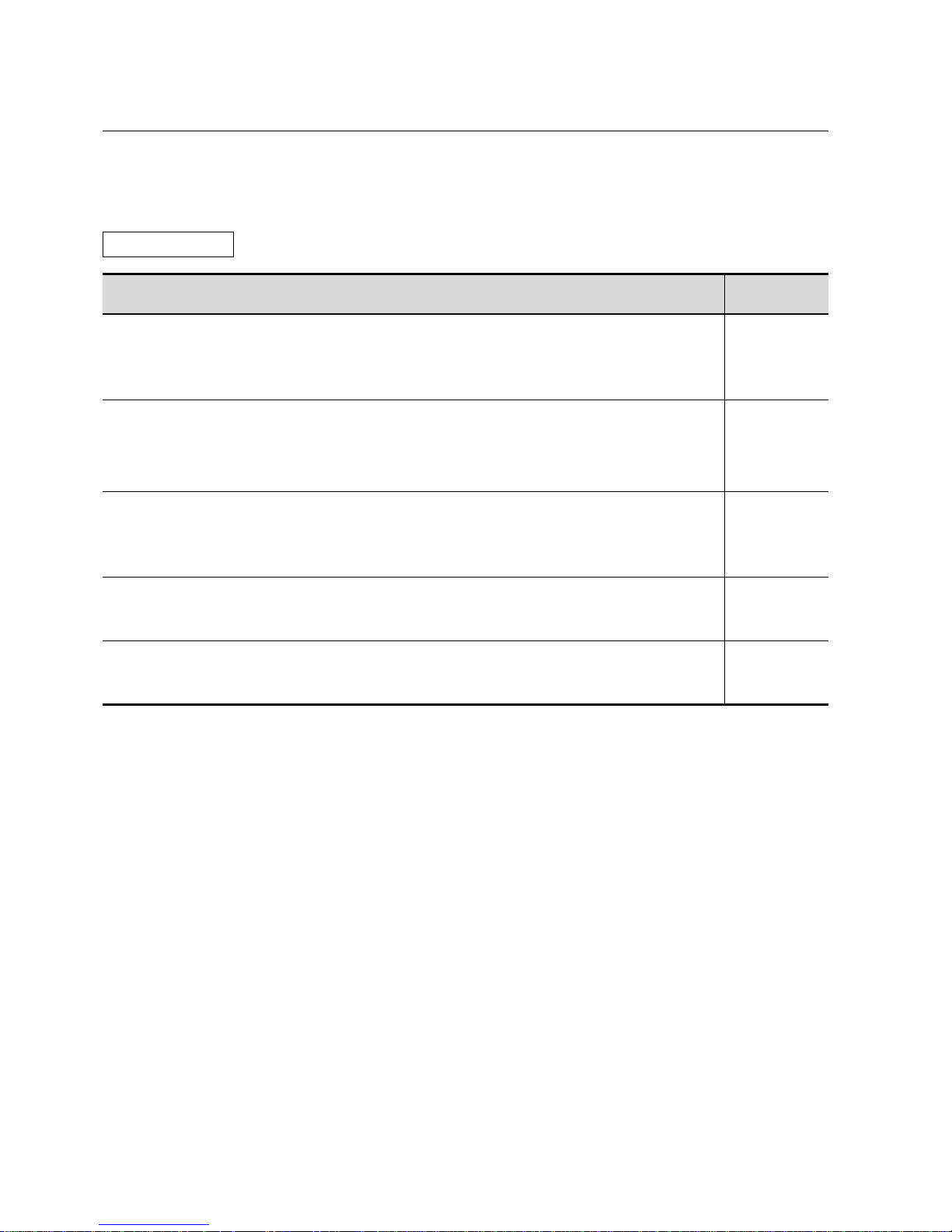
2 About Manual
The following manuals related to GOT1000 series are available. Refer to each manual in accordance
with the intended use.
(1) Installation of the software programs Drawing Data transfer
For operations from creating project data to transferring data to GOT, refer to the following
manuals.
*1 Stored in the GT Works2/GT Designer2 in PDF format.
Purpose
GT Designer2 Version Basic
Operation/Data Transfer Manual
*1
GT Designer2 Version
Screen Design Manual
*1
Installing product on PC
Creating projects
Creating screens
Drawing figures
Making Common Settings
Placing/Setting objects
Transferring data to GOT
Detailed
Detailed
Detailed
Detailed
Overview
Detailed
Overview
Detailed
Detailed
1 - 3
(2) Installing a GOT Connecting to a PLC
For the operations from installing a GOT to communicating with a PLC CPU, refer to the following manuals
.
*1 Stored in the GT Works2/GT Designer2 in PDF format.
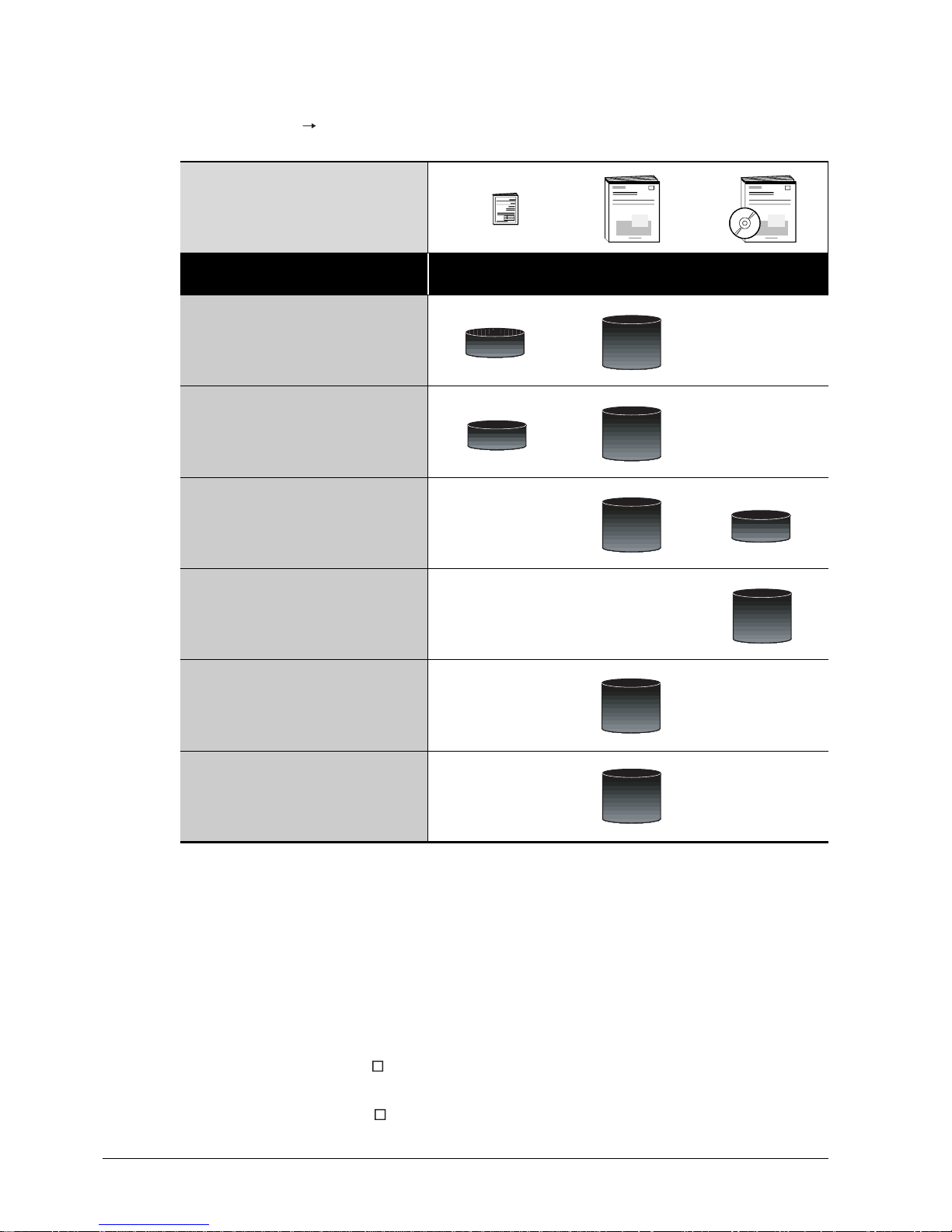
(3) Other manuals
The following manuals are also available.
The following manuals are stored in the GT Works2/GT Designer2 in PDF format.
(a) GOT1000 Series Extended/Option Functions Manual
Describes functions for more efficient debugging as the ladder monitor function, system
monitor function and A list edit function.
(b) GOT1000 Series Gateway Functions Manual
Describes how to use the gateway function.
(c) GT Simulator2 Version Operating Manual
Describes how to simulate the created project data with the GT Simulator2.
(d) GT Converter2 Version Operating Manual
Describes how to use the GT Converter2.
Purpose
GT15 General Description
GT11 General Description
GT15 User's Manual
GT11 User's Manual
GOT1000 Series
Connection Manual
*1
Confirming part names and
specifications of the GOT
Confirming the GOT installation method
Confirming the mounting method for
communication units or option devices
Confirming the PLC connection method
Confirming the utility operation method
Confirming error codes (system alarm)
displayed on the GOT
(Included)
Overview
Detailed
Overview
Detailed
Detailed
Overview
Detailed
Detailed
Detailed

1.1 Features
1 - 4
1
OVERVIEW
2
SYSTEM
CONFIGURATION
3
SPECIFICATIONS
4
PART NAME AND
SETTINGS
5
EMC AND LOW
VOLTAGE
DIRECTIVE
6
INSTALLATION
7
WIRING
8
OPTION
1.1 Features
(1) Improved monitoring performance and connectivity to FA devices
• Using of TFT color liquid crystal display (high intensity, wide angle view and high definition type)
provides clear full-color display and displays small characters clearly. (Displays digital images of
BMP and other formats in 65536 colors.)
*1
• Provides multi-language display function based on Unicode2.1 True Type font and high-speed
drawing of beautiful text.
• High speed monitoring through high speed communication at maximum of 115.2kbps.
• High speed display and high speed touch switch response.
(2) More efficient GOT operations including screen design, startup, adjustment, management and
maintenance works
• 9MB user memory is included as standard. (Memory capacity can be expanded up to 57MB by
increasing the option memory)
*1
• CF card interface is included as standard
• Font installation is available to increase the system fonts.
• Combined use of 4 types of alarms (system alarm, user alarm, alarm history, alarm popup
display) realizes more efficient alarm notification.
• Maintenance timing report function is available that measures the backlight energization time
and notifies of maintenance time.
• The USB connector is positioned on the GOT front. This enables the system startup to be
performed more efficiently using FA device startup tool, and eliminates the necessity of indirect
works (opening and closing the control panel, cable replacement, cable rewiring) in order to
improve the working efficiency.
• The blown backlight bulb can be confirmed even during screen saving, with the blinked POWER
LED at backlight shutoff detection.
(3) Enhanced support of FA device setup tools
• Transferring or monitoring the sequence programs using the personal computer connected to
GOT, during direct connection to Q, QnA, A or FX series PLC CPU, or computer link connection
to A, QnA or Q series (FA Transparent function).
*1 For GT1595-X, GT1585-S, GT1575-S, GT1575-V, GT1565-V
1 - 5
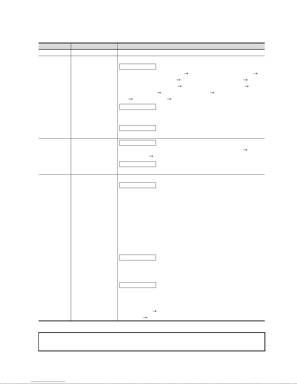
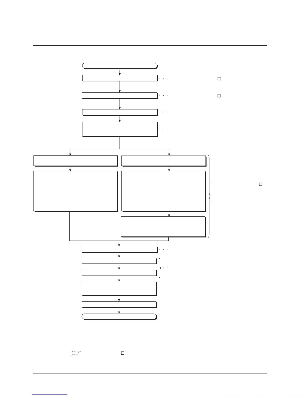
1.2 Rough Pre-operation Procedure
1.2 Rough Pre-operation Procedure
The outline procedure before operating GOT is shown.
* 1 Project data can be also downloaded/uploaded via Ethernet.
For download/upload of project data via Ethernet, BootOS and standard monitor OS should be installed in the
GOT in advance so that the GOT and PC can communicate with each other via Ethernet by setting
Communication Settings.
Refer to the following manual for details.
GT Designer2 Version Basic Operation/Data Transfer Manual (Chapter 8 TRANSFERRING DATA)
Start
Install GT Designer2 in the PC.
Create project data.
Wire for the GOT power supply.
Mount the option function board or multi-color
display board.
(As necessary)
Connect GOT and PC with a USB cable or
RS-232 cable.
Insert the memory card in the PC.
Install and download the OS program, project data
installed in the PC to the GOT.
1) Install standard monitor OS, communication driver,
extended function OS, option OS to the GOT.
After installation is completed, the GOT
automatically restarts.
2) Download the project data created by the PC.
*1
Write the OS, program, project data installed in the PC
in the memory card.
1) Write the standard monitor OS, communication
driver, extended function OS, option OS, project
data in the memory card.
Install the memory card to the GOT to install and
download the standard monitor OS, communication
driver, extended function OS, option OS, project data
to the GOT.
Mount units to GOT.
Check the Communication settings.
Connect the GOT and controller with a cable.
Turn on the power supply of GOT and
the system of the connection destination.
Start the monitor.
End
When transfer data via a cable. When transfer data via the memory card.
Refer to Chapter 7 WIRING
Refer to Chapter 8 Option.
Refer to Chapter 8 OPTION.
Refer to GOT1000 Series Connection Manual.
Refer to GT Designer2 Version
Basic Operation/Data Transfer Manual
Refer to GT Designer2 Version Screen Design Manual
Refer to GT Designer2 Version
Basic Operation/Data Transfer
Manual
Refer to Chapter 18 INSTALLATION
OF COREOS, BOOTOS AND
STANDARD OS in this manual for
the operations of GOT.
2.1 Overall Configuration
2 - 1
1
OVERVIEW
2
SYSTEM
CONFIGURATION
3
SPECIFICATIONS
4
PART NAME AND
SETTINGS
5
EMC AND LOW
VOLTAGE
DIRECTIVE
6
INSTALLATION
7
WIRING
8
OPTION
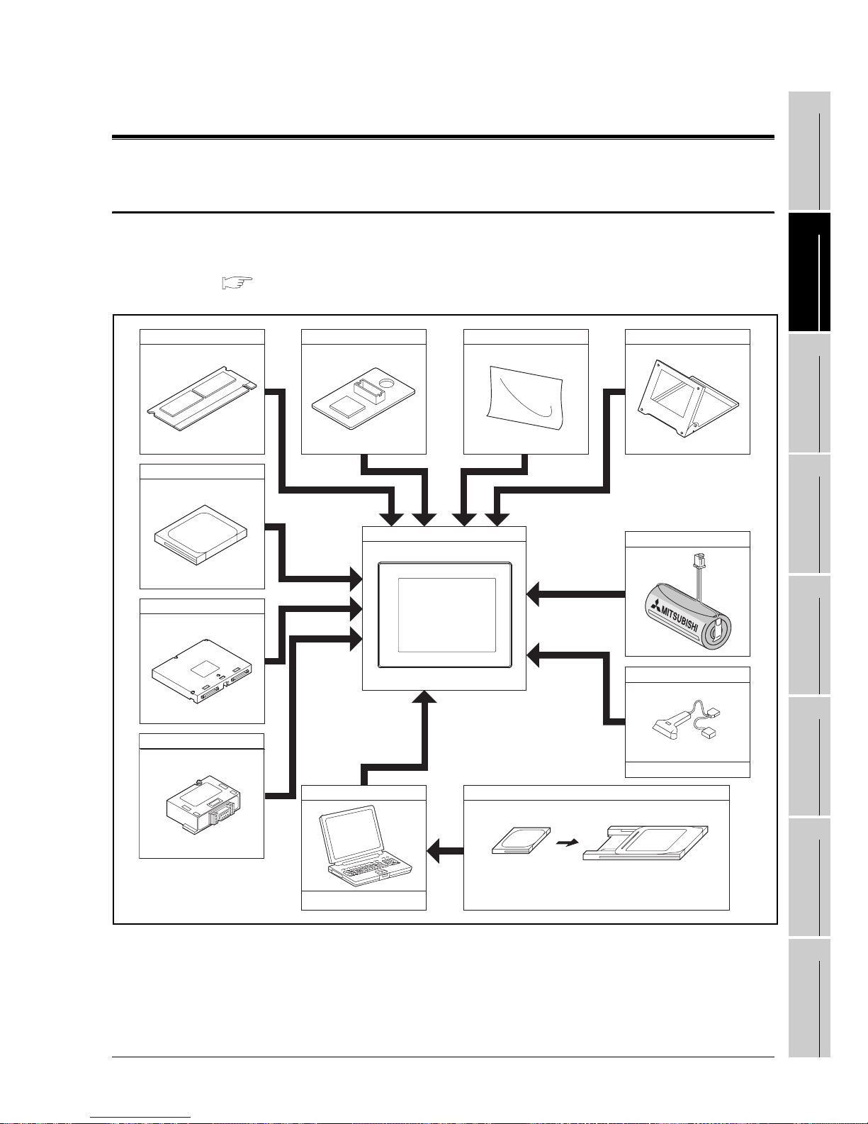
2. SYSTEM CONFIGURATION
2.1 Overall Configuration
The overall configuration of GOT is as follows.
For the connection methods applicable to GOT1000 series and cable, refer to the following.
GOT1000 Series Connection Manual
Option function board
CF card
Communication Unit
RS-422 conversion unit
Multi-color display board
GOT
Personal computer
Commercially available
Memory card
CF card Memory card adaptor
Protective sheet Stand
Battery
Bar code reader
Commercially available

2 - 2
2.2 Component List
2.2 Component List
(1) Explanation of the GOT model name
(2) Explanation of the option model name
GOT 1000 series GT15/GT11
*1 For models supporting 65536 colors, refer to the following.
2.2.1 GOT
GT1575
Panel color type
9 : 15"
8 : 12.1"
7 : 10.4"
6 : 8.4"
5 : 5.7"
5 : 256 colors*1
2 : 16 colors
0 : Monochrome (White/Black), 16 gray scale
X : 1024 768 (XGA)
S : 800 600 (SVGA)
V : 640 480 (VGA)
Q : 320 240 (QVGA)
A : 100 to 240VAC
D : 24VDC
T : TFT color (High intensity, Wide angle view)
N : TFT color
S : STN color
L : STN monochrome
Screen size type
Model type
Resolution
Power type
Display device type
B : Black
90 : Dedicated for 15"
80 : Dedicated for 12.1"
75 : Common for 10.4", 8.4"
70 : Dedicated for 10.4"
60 : Dedicated for 8.4"
50 : Dedicated for 5.7"
15 : Dedicated for GT15
11 : Dedicated for GT11
09 :
05 :
01 :
Common for GT15/GT11
GT
 Loading...