

Page 1

SOFTWARE MANUAL
FX-PCS-DU/WIN-E
Page 2

Page 3

FX Series Programmable Controllers
FX-PCS-DU/WIN-E
Software Manual
Manual number : JY992D68301 Manual revision : G Date : February 2003
Foreword
• This manual contains text, diagrams and explanations which will guide the reader in the correect
installation and operation of the FX-PCS-DU/WIN-E.
• Before attempting to install or use the FX-PCS-DU/WIN-E this manual should be read and understood.
• If in doubt at any stage of the installation of the FX-PCS-DU/WIN-E always consult a professional
electrical engineer who is qualified and trained to the local and national standards which apply to the
installation site.
• If in doubt about the operation or use of the FX-PCS-DU/WIN-E please consult the nearest Mitsubisi
Electric distributor.
• This manual is subject to change without notice.
i
Page 4

FX Series Programmable Controllers
MS,MS-DOS and Windows are registered trademarks of Microsoft Corporation.
IBM and AT are registered trademarks of International Business Machines Corporation.
All other brand and product names are trademarks or registered trademarks of theirrespective owners.
ii
Page 5

FX Series Programmable Controllers
FAX BACK
Mitsubishi has a world wide reputation for its efforts in continually developing and pushing back the
frontiers of industrial automation. What is sometimes overlooked by the user is the care and attention to
detail that is taken with the documentation. However, to continue this process of improvement, the
comments of the Mitsubishi users are always welcomed. This page has been designed for you, the
reader, to fill in your comments and fax them back to us. We look forward to hearing from you.
Fax numbers: Your name: .........................................................
Mitsubishi Electric.... ...........................................................................
America (01) 847-478-2253 Your company:....................................................
Australia (02) 638-7072 ...........................................................................
Germany (0 21 02) 4 86-1 12 Your location:......................................................
Spain (34) 93-589-1579 ...........................................................................
United Kingdom (01707) 278-695
Please tick the box of your choice
!
!
!
!
!
!
Good
Ye s
Tidy
Ye s
Ye s
Good
What condition did the manual arrive in?
Will you be using a folder to store the manual?
What do you think to the manual presentation?
Are the explanations understandable?
Which explanation was most difficult to understand: ................................................................................
..................................................................................................................................................................
Are there any diagrams which are not clear?
If so,which:................................................................................................................................................
What do you think to the manual layout?
If there one thing you would like to see improved, what is it? ...................................................................
..................................................................................................................................................................
..................................................................................................................................................................
Could you find the information you required easily using the index and/or the contents, if possible please
identify your experience: ...........................................................................................................................
..................................................................................................................................................................
..................................................................................................................................................................
..................................................................................................................................................................
..................................................................................................................................................................
Do you have any comments in general about the Mitsubishi manuals? ...................................................
..................................................................................................................................................................
..................................................................................................................................................................
..................................................................................................................................................................
..................................................................................................................................................................
Thank you for taking the time to fill out this questionnaire. We hope you found both the product and this
manual easy to use.
!
Minor damage
!
No
!
Unfriendly
!
Not too bad
!
No
!
Not too bad
!
Unusable
!
Unusable
!
Unhelpful
iii
Page 6

FX Series Programmable Controllers
Guidelines for the safety of the user and protection of the FX-PCS-DU/WIN-E
This manual provides information for the use of the FX-PCS-DU/WIN-E. The manual has been written to be
used by trained and competent personnel. The definition of such a person or persons is as follows;
a ) Any engineer who is responsible for the planning, design and construction of automatic equipment
using the product associated with this manual should be of a competent nature,trained and qualified
to the local and national standards required to fulfill that role. These engineers should be fully aware
of all aspects of safety with regards to automated equipment.
b ) Any commissioning or service engineer must be of a competent nature,trained and qualified to the
local and national standards required to fulfill that job. These engineers should also be trained in the
use and maintenance of the completed product. This includes being completely familiar with all
associated documentation for the said product. All maintenance should be carried out in accordance
with established safety practices.
c ) All operators of the completed equipment should be trained to use that product in a safe and
coordinated manner in compliance to established safety practices. The operators should also be
familiar with documentation which is connected with the actual operation of the completed equipment.
Note: the term 'completed equipment' refers to a third party constructed device which contains or uses the
product associated with this manual.
Notes on the symbology used in this manual
At various times through out this manual certain symbols will be used to highlight points of information which
are intended to ensure the users personal safety and protect the integrity of equipment. Whenever any of the
following symbols are encountered its associated note must be read and understood. Each of the symbols
used will now be listed with a brief description of its meaning.
iv
Page 7
FX Series Programmable Controllers
Hardware warnings
Indicates that the identified danger WILL cause physical and property damage.
Indicates that the identified danger could POSSIBLY cause physical and property damage.
Indicates a point of further interest or further explanation.
Software warning
Indicates special care must be taken when using this element of software.
Indicates a special point which the user of the associate software element should be aware of.
Indicates a point of interest or further explanation
.
v
Page 8

FX Series Programmable Controllers
vi
Page 9

FX Series Programmable Controllers
Contents
1. Introduction ..........................................................................................1-1
1.1 Outline ............................................................................................................... 1-1
1.1.1 List of models compatible with the software DU/WIN ............................................. 1-1
1.1.2 Product configuration (accessory list) .................................................................... 1-1
1.1.3 Major features of the software ................................................................................ 1-2
1.2 How to read this manual .................................................................................... 1-3
1.2.1 Contents described in manual ................................................................................ 1-3
1.2.2 Abbreviations in the text ......................................................................................... 1-5
2. Installation ............................................................................................ 2-1
2.1 Software installation procedure ......................................................................... 2-1
2.2 Operating environments of the personal computer ............................................2-1
2.3 System configuration .........................................................................................2-2
2.4 Installation (setup) .............................................................................................2-4
2.4.1 Starting up the setup program ................................................................................ 2-4
2.5 Deleting the application .....................................................................................2-5
2.6 Installation information ....................................................................................... 2-6
2.6.1 Installation destination directory ............................................................................. 2-6
2.6.2 Upper compatibility of the drawing file .................................................................... 2-7
3. Starting up and Terminating the Program ............................................3-1
3.1 Starting up the program .....................................................................................3-1
3.1.1 Program type .......................................................................................................... 3-1
3.1.2 Starting up the program .......................................................................................... 3-2
3.2 Screen configuration of the DU/WIN .................................................................. 3-3
3.2.1 Basic screen ........................................................................................................... 3-3
3.3 Terminating the program ................................................................................... 3-4
4. What You Should Know Before Starting Drawing ................................4-1
4.1 Name of each object on the screen ................................................................... 4-1
4.2 Types of the DU screen and the F940GOT screen ...........................................4-3
4.3 Objects constituting the screen .......................................................................... 4-5
4.4 Functions of tools ...............................................................................................4-6
4.4.1 Tool type ................................................................................................................. 4-7
4.4.2 Modifying the display layout of the tool bar ............................................................ 4-8
4.5 Common change contents in version upgrade of DU/WIN-E ............................4-9
4.6 Before starting screen creation for F920GOT-K ..............................................4-10
4.6.1 How to read this manual ....................................................................................... 4-10
4.6.2 Functions and objects provided in the F940GOT but not provided in the
F920GOT-K ................................................................................................................... 4-10
4.6.3 Difference in specifications between the F920GOT-K and the F940GOT ........... 4-11
4.6.4 Colors displayed in the F920GOT-K and the screen creation software ............... 4-11
4.6.5 Changing the backlight color ................................................................................ 4-11
4.7 Before starting screen creation for F930GOT(-K) ............................................ 4-12
4.7.1 How to read this manual ....................................................................................... 4-12
4.7.2 Functions provided in the F940GOT but not provided in the F930GOT(-K) ......... 4-12
4.7.3 Difference in specifications between the F930GOT(-K) and the F940GOT ......... 4-12
4.7.4 Colors displayed in the F930GOT(-K) and the screen creation software ............. 4-12
4.8 Cautions on screen creation in the GOT-F900 Series .....................................4-13
4.8.1 Arrangement of "Touch Key", "Number" and "Ascii" objects ................................ 4-13
4.8.2 Key code and function of touch key ..................................................................... 4-15
4.8.3 High-quality characters and 6¥8-dot font ............................................................. 4-16
vii
Page 10

FX Series Programmable Controllers
Contents
5. Preparation for Drawing and Basic Options ......................................... 5-1
5.1 Screen creation procedure ................................................................................ 5-1
5.2 Let's start to create the screen. ..........................................................................5-2
5.2.1 Preparation for drawing (Screen window) .............................................................. 5-2
5.2.2 Creating the screen data newly [New] .................................................................... 5-5
5.2.3 Reading and editing the existing screen data (Open) ............................................ 5-7
5.2.4 Readable files ......................................................................................................... 5-8
5.2.5 Selecting the screen No. and performing additional deletion (Screen List) ............ 5-9
5.2.6 Adding and changing the screen No. (Screen Header) ........................................ 5-10
5.2.7 Adding, deleting and sorting objects (Object List) ................................................ 5-12
5.2.8 Setting the security for system screens ................................................................ 5-14
5.3 Let’s display characters ................................................................................... 5-15
5.4 Let’s turn on output using touch key switch ..................................................... 5-18
5.5 Let’s display numeric value (T, C, D) ...............................................................5-22
5.6 Let’s change over screen ................................................................................. 5-26
5.6.1 Screen No. 0 for screen changeover .................................................................... 5-27
5.6.2 Screen No. 1 for screen changeover .................................................................... 5-31
5.6.3 Screen No. 2 for screen changeover .................................................................... 5-35
5.6.4 Setting of control device ....................................................................................... 5-36
5.6.5 Setting of "Change Screen (by PLC)" object ........................................................ 5-38
5.6.6 Creation of sequence program (reference) .......................................................... 5-41
6. Menu Bar Functions .............................................................................6-1
6.1 Types and functions of the menu bar ................................................................6-1
6.2 Jobs offered by the “File” command .................................................................. 6-3
6.2.1 Saving the screen data to the disk ......................................................................... 6-4
6.2.2 File formats which can be read and saved ............................................................. 6-5
6.2.3 Creating the printout title ........................................................................................ 6-6
6.2.4 Checking the preview before printout ..................................................................... 6-7
6.2.5 Setting and starting printout ................................................................................... 6-8
6.2.6 Samples of printout .............................................................................................. 6-10
6.3 Jobs offered by the “Edit” command ................................................................6-11
6.3.1 Deleting, transferring and copying objects (Screen window) ............................... 6-11
6.3.2 Searching the use destination screen No. based on the object name ................. 6-20
6.4 Jobs offered by the “View” command ..............................................................6-21
6.4.1 Displaying the screen list on the front .................................................................. 6-22
6.4.2 Creating and editing the text library ...................................................................... 6-23
6.4.3 Creating and editing the image library .................................................................. 6-25
6.4.4 Creating and editing the device comment ............................................................ 6-29
6.4.5 Creating and setting the alarm message .............................................................. 6-31
6.4.6 Creating and setting the data for the data file ...................................................... 6-34
6.4.7 Setting the time channel ....................................................................................... 6-37
6.4.8 Setting the sampling condition ............................................................................. 6-38
6.4.9 Creating logos, symbols, etc. using the external character creation function ...... 6-39
6.4.10 Outputting the screen image to the printer (hard copy) ..................................... 6-41
6.4.11 Arranging the DU operation environment by the system setting ........................ 6-42
6.5 Jobs offered by the “Transfer” command ......................................................... 6-51
6.5.1 Preparation for data transfer between the DU ...................................................... 6-53
6.5.2 Executing transfer of the drawing data ................................................................. 6-57
6.5.3 OS transfer function in the F940GOT ................................................................... 6-61
6.5.4 Changing over the port for communication setup ................................................. 6-63
viii
Page 11

FX Series Programmable Controllers
Contents
6.6 Objects offered by the “Other” command ........................................................6-65
6.6.1 Error check for the screen data ............................................................................ 6-66
6.6.2 Displaying the memory use capacity .................................................................... 6-67
6.6.3 Displaying the sampling result .............................................................................. 6-68
6.6.4 Displaying the alarm history ................................................................................. 6-70
6.6.5 Displaying the alarm frequency ............................................................................ 6-72
6.7 Functions offered by the Window menu ..........................................................6-74
6.7.1 Displaying the grid ................................................................................................ 6-74
6.7.2 Setting the grid display ......................................................................................... 6-75
6.7.3 Enlarging and diminishing the screen window ..................................................... 6-75
6.8 Help menu .......................................................................................................6-76
6.8.1 Topics index function ............................................................................................ 6-76
6.8.2 Checking the version of the DU/WIN software ..................................................... 6-77
7. Common Drawing Operations ..............................................................7-1
7.1 Rule on object selection .....................................................................................7-1
7.1.1 Editing the objects to be displayed on the screen .................................................. 7-1
7.1.2 Selecting the objects to be displayed on the screen and the objects not to be
displayed on the screen .................................................................................................. 7-2
7.1.3 Editing the key objects ........................................................................................... 7-4
7.1.4 Editing the attribute objects (Scroll and Flashing) in the FX-10DU-E ..................... 7-6
7.2 Specifying object elements using data files (indirect specification) ................... 7-7
7.3 Assigning character strings and graphics in libraries to the DU ........................ 7-9
7.4 DU screen specifications ................................................................................. 7-10
8. Object Function Description ................................................................. 8-1
8.1 Setting the "Text" object .................................................................................... 8-1
8.1.1 Text ....................................................................................................................... 8-2
8.1.2 Library Text ............................................................................................................ 8-4
8.2 Setting the "Image" object ................................................................................. 8-6
8.2.1 Image ..................................................................................................................... 8-8
8.2.2 Library Image ....................................................................................................... 8-10
8.3 Setting the "Graph" object ............................................................................... 8-12
8.3.1 Bar Graph ............................................................................................................. 8-14
8.3.2 Trend Graph (Sampling) ....................................................................................... 8-18
8.3.3 Circle Graph ......................................................................................................... 8-22
8.3.4 Panel Meter .......................................................................................................... 8-24
8.3.5 Proportional Bar Graph ....................................................................................... 8-26
8.3.6 Proportional Pie Graph ........................................................................................ 8-30
8.3.7 Line Graph ............................................................................................................ 8-34
8.4 Setting indicators (Indicator) ............................................................................ 8-37
8.4.1 Text indicator ....................................................................................................... 8-38
8.4.2 Image indicator ..................................................................................................... 8-41
8.4.3 Indicator ...............................................................................................................8-42
8.4.4 Label indicator ...................................................................................................... 8-43
8.4.5 Change screen .................................................................................................... 8-46
8.4.6 Output Indicator .................................................................................................... 8-47
8.4.7 Setting "Overlay Screen" ...................................................................................... 8-48
8.4.8 Buzzer .................................................................................................................. 8-49
8.5 Setting the date/time display (Date/Time) ........................................................8-50
8.5.1 Date ...................................................................................................................... 8-51
8.5.2 Time ....................................................................................................................8-52
8.6 Setting the character code (Ascii) ....................................................................8-53
ix
Page 12

FX Series Programmable Controllers
8.7 Setting the numeric (Number) ..........................................................................8-57
8.8 Setting the box (Box) .......................................................................................8-63
8.9 Setting the circle (Circle) .................................................................................. 8-66
8.10 Setting the line (Line) .....................................................................................8-69
8.11 Setting the touch key (TouchKey) .................................................................. 8-71
8.12 Setting the keyboard (Keyboard) ................................................................... 8-77
8.13 Setting the key function ................................................................................. 8-80
8.13.1 Key function object ............................................................................................. 8-82
8.13.2 Switch ................................................................................................................. 8-83
8.13.3 Send data bank .................................................................................................. 8-86
8.13.4 Change screen ................................................................................................... 8-87
8.13.5 Data setting ........................................................................................................ 8-88
8.13.6 Increment and Decrement .................................................................................. 8-90
8.13.7 Write constant .................................................................................................... 8-92
8.14 Setting the objects related to the FX-10DU-E ...............................................8-93
8.15 Setting dedicated to handy GOT ................................................................... 8-95
8.15.1 Assignment of LEDs of operation switches ........................................................ 8-96
8.15.2 Setting of grip switch .......................................................................................... 8-97
8.16 Setting of alarm ..............................................................................................8-98
8.16.1 Alarm List (L) ...................................................................................................... 8-99
8.16.2 Alarm History (R) .............................................................................................. 8-102
Contents
9. Related Information .............................................................................. 9-1
9.1 Index ..................................................................................................................9-1
9.1.1 Function index and applicable DU type .................................................................. 9-1
9.1.2 Object name index and applicable DU type ........................................................... 9-4
9.2 Additional functions and corresponding version of the DU ................................ 9-6
9.3 Cautions on using the screen data for an other type of PLC ...........................9-10
9.3.1 Cautions on using the screen data for an other type of PC .................................. 9-10
9.3.2 Cautions on change of the DU type ..................................................................... 9-10
9.3.3 Cautions on DU type setting when the drawing data is transferred (written)
to the DU ....................................................................................................................... 9-10
9.4 Device list for each PC .................................................................................... 9-11
9.5 Control devices ................................................................................................9-25
9.5.2 Screen specification registers
(The table below indicates the case where D0 is assigned.) ........................................ 9-28
9.6 Number of objects registered and data size ....................................................9-29
9.7 Data transfer between a general-purpose ROM writer
(preparation before transfer such as connection) .................................................. 9-36
9.8 Image library data list ....................................................................................... 9-41
9.8.1 Frame .................................................................................................................. 9-41
9.8.2 Indicator ...............................................................................................................9-44
9.8.3 Switch ...................................................................................................................9-46
9.8.4 Other(mark) ......................................................................................................... 9-47
9.8.5 List of images added in Ver. 2.50 and later .......................................................... 9-48
9.9 Troubleshooting ............................................................................................... 9-50
9.10 Key code list ..................................................................................................9-52
x
Page 13
FX Series Programmable Controllers
1 Introduction
2 Installation
3 Starting up and Terminating the Program
4
What You Should Know Before Starting Drawing
5 Preparation for Drawing and Basic Operations
6 Menu Bar Functions
7 Common Drawing Operations
8 Object Function Description
9 Related Information
Page 14

FX Series Programmable Controllers
Page 15
FX Series Programmable Controllers Introduction 1
1. Introduction
This section describes the major functions of the software FX-PCS-DU/WIN-E and the outline of this manual.
The applicable data access units are also described here. Make sure to read this section before using the
software.
1.1 Outline
The software package FX-PCS-DU/WIN-E (hereafter referred to as "software DU/WIN-E") is a screen
creation software for graphic operation terminals (GOT-F900) and data access units (DU) running on the
Microsoft Windows 95/98/Me/NT4.0 (hereafter referred to as "Windows").
1.1.1 List of models compatible with the software DU/WIN
Table:1.1
FX-PCS-DU/WIN-E
version
FX-10DU-E
V1.0 V2.0 V2.1 V2.2 V2.3 V2.4 V2.5 V2.6 V2.7 V2.8
""""""""""
*3
FX-25DU-E
FX-30DU-E
FX-40DU-ES
FX-40DU-TK-E
FX-50DU-TK-E
FX-50DU-TKS-E
F940GOT-SBD-E
F940GOT-LBD-E
F940GOT-SWD-H-E
F940GOT-LWD-H-E
F930GOT-BWD-E
F940WGOT-TWD-E
F920GOT-BBD5-K-E
F930GOT-BBD-K-E
*1 Screen creation in the longitudinal installation is supported in the F930GOT.
*2 Screen creation with screen division into 2 or 3 portions is not supported.
*3 FX
and FX1N Series PLCs are applicable to the screen data transfer function of FX-10DU.
1S
""""""""""
""""""""""
""""""""""
""""""""""
""""""""""
"""""""""
""""""""
*2
1.1.2 Product configuration (accessory list)
""""
"" "
"
*1
"
"
*1
"
"
"
*1
Check the software DU/WIN while referring to this checklist to confirm that the following accessories are
supplied.
Product model:FX-PCS-DU/WIN-E
• System disk SW0PC-FXDU/WIN-E
Floppy disk 3.5-inch (1.44 MB) 3 disks
• Manual (this manual) JY992D68301
The cable to connect the DU and the personal computer is offered as an option.Check the system
configuration, and use a cable suitable to your personal computer.
1-1
Page 16
FX Series Programmable Controllers
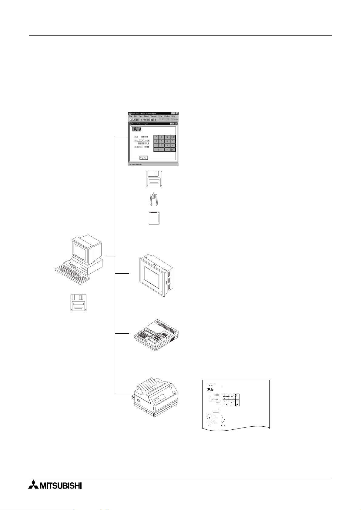
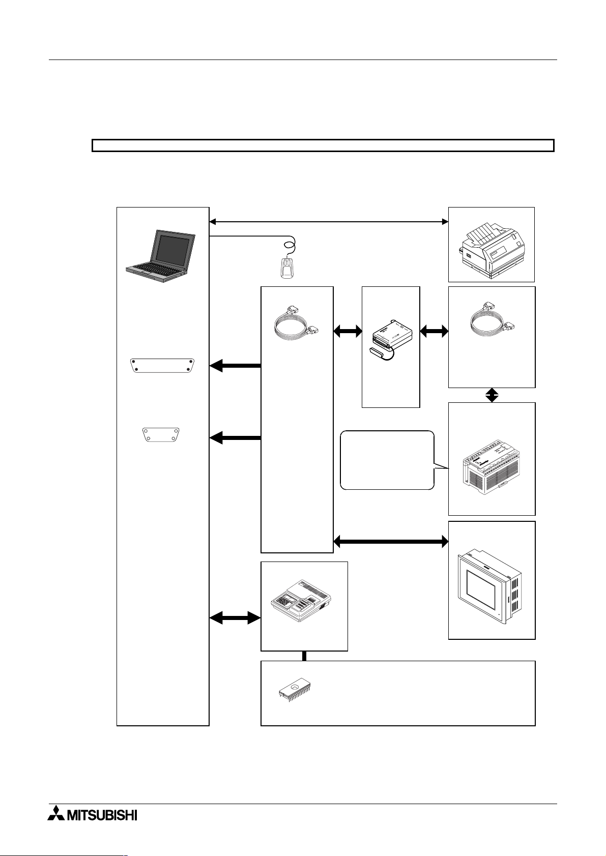
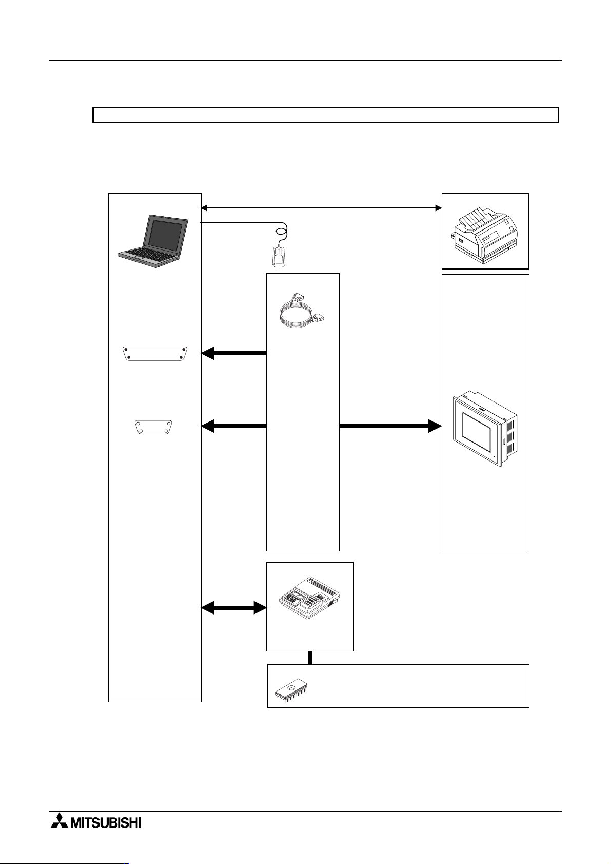
1.1.3 Major features of the software
The software DU/WIN has the diversified convenient functions as follows. The operability is excellent
because the features of the Windows are offered and the graphic interface is provided. Two or more
applications and two or more screen data files can be started up at the same time. You can edit the data while
looking at two or more DU screens at the same time.
Screen edition
Introduction 1
• Two or more screen files and screen displays can
be opened at the same time.
• The DU screen display size can be enlarged. The
position of each component can be adjusted
easily.
• Data can be saved in the storage media
connected to the personal computer such as a
floppy disk or hard disk.
• The drawing software data of the DOS version is
available due to the upper compatibility.
• The basic operations are performed using the
mouse.
• This software is similar to a general Windows
application, so can be easily learned.
• The company logo, symbols, etc. can be created
using the external character creation function.
• The libraries for character examples and graphics
can be created.
SW0PC-FXDU/WIN-E
Data access unit
P
O
W
E
General-purpose ROM writer
Printer
• The screen data can be transferred to the DU.
• The screen data saved in the DU can be read
and edited.
• The FX-25DU-E to the FX-50DU-TKS-E are
applicable.
• The FX-10DU-E is also applicable (However, the
drawing software of the DOS version is not
applicable yet.)
• The screen data can be written to and read from
the EP-ROM memory.
Use appropriate communication software when
transferring the data between a ROM writer.The
DU/WIN software can save the data in the Intel
Hex format offered for transfer between a ROM
writer.
• The graphic (screen data) can be created.
Sampling data
Alarm history
Screen name list, etc.
1-2
Page 17
FX Series Programmable Controllers Introduction 1
1.2 How to read this manual
This paragraph describes the description format, the abbreviations in the text, the key symbols, etc. adopted
in this manual.
1.2.1 Contents described in manual
This manual adopts the following format. Refer to this page for index.
In "9. Related Information", you can utilize the function list and the object list for index. Refer to Section 9
also.
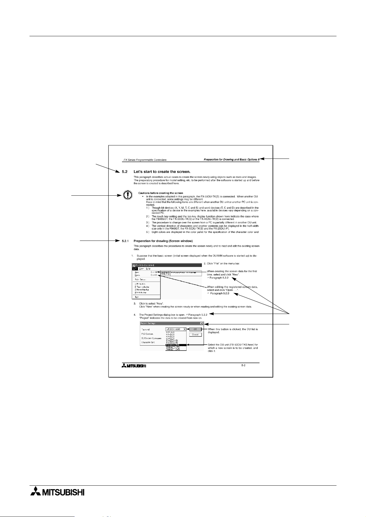
General format of manual
Paragraph title
Detailed explanation
of each paragraph
Note
Notes and cautions
described in main
text above
Subtitle
Section title
Reference page
Screen
1-3
Page 18
FX Series Programmable Controllers
Introduction 1
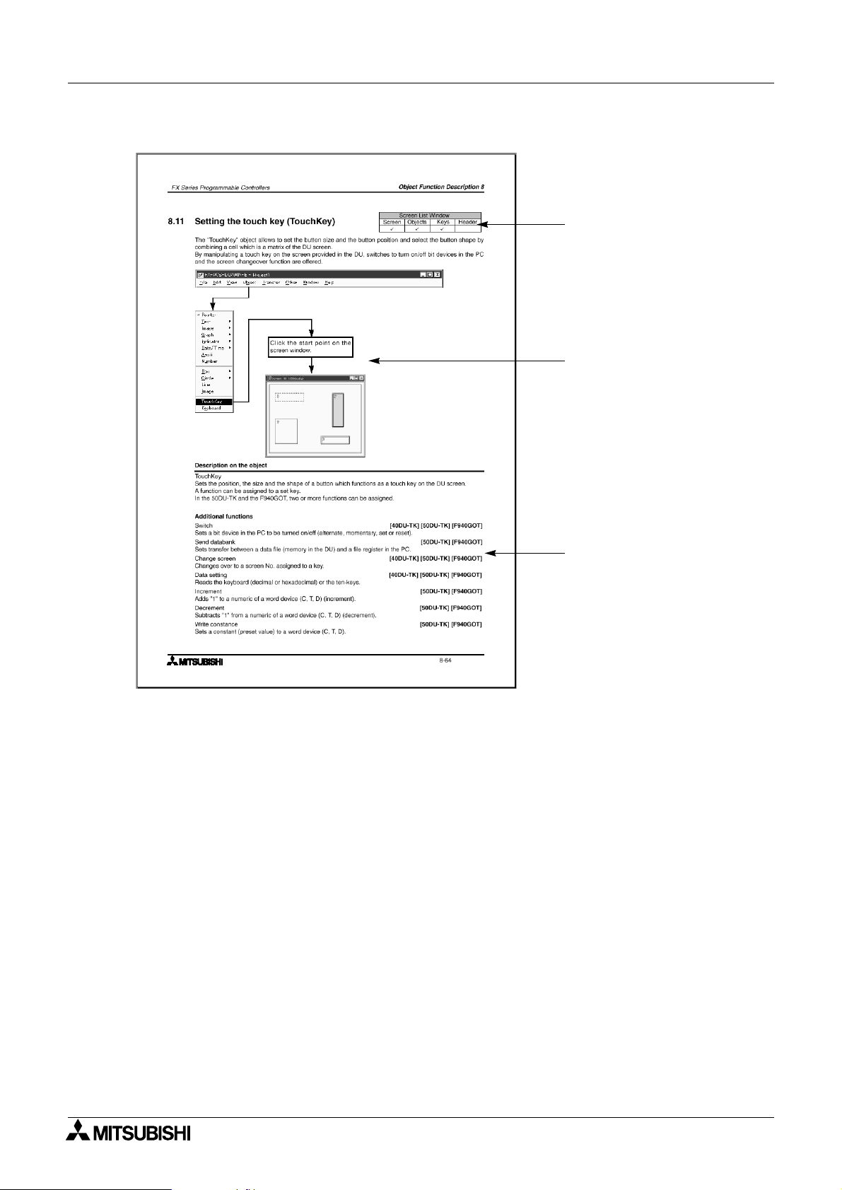
Format of "8. Object Function Description"
Window which can be set
Paragraph 7.1
Operation flow from the tool
bar (The Screen window
indicates an example after an
object is created. The object
dialog box is actually
displayed.)
Applicable models
1-4
Page 19

FX Series Programmable Controllers Introduction 1
1.2.2 Abbreviations in the text
The following terms may be abbreviated in the text in this manual.
• Microsoft Windows®95, 98, NT4.0 and 2000 may be referred to as “Windows”
• The software kit for creating the display screen “FX-PCS-DU/WIN-E (for Windows)” may be referred to
as “software DU/WIN”.
• The general-purpose personal computer PC/AT compatible machine may be referred to as “personal
computer”.
A floppy disk may be referred to as “FD”. A floppy disk drive may be referred to as “FD drive”. Each of
them may be referred to as “disk”.
• The data access unit may be referred to as “DU”. Each DU model may be referred to as follows.
- Data access unit FX-10DU-E - - - - - - - - - - - - - - - - - - - - - - - - - - - - - - - - - 10DU
- Data access unit FX-25DU-E - - - - - - - - - - - - - - - - - - - - - - - - - - - - - - - - - 25DU
- Data access unit FX-30DU-E - - - - - - - - - - - - - - - - - - - - - - - - - - - - - - - - - 30DU
- Data access unit FX-40DU-ES - - - - - - - - - - - - - - - - - - - - - - - - - - - - - - - - 40DU
- Data access unit FX-40DU-TK-E - - - - - - - - - - - - - - - - - - - - - - - - - - - - - - 40DU-TK
- Data access unit FX-50DU-TK-E, FX-50DU-TKS-E - - - - - - - - - - - - - - - - - 50DU-TK
• The graphic operation terminal is referred to as "GOT-F900".
- Graphic operation terminal Model F94#GOT-SWD-E/F94#GOT-LWD-E - - F940GOT
- Graphic operation terminal Model F940WGOT-TWD-E - - - - - - - - - - - - - - - F940WGOT
- Graphic operation terminal Model F930GOT-BWD-E - - - - - - - - - - - - - - - - F930GOT
- Graphic operation terminal Model F930GOT-BBD-K-E - - - - - - - - - - - - - - -F930GOT-K
(The abbreviation notation of the F930GOT in the text is included. Refer to the following graphic
operation terminal if it has the same functions as the F940GOT in the text.)
- Graphic operation terminal Model F920GOT-BBD5-K-E - - - - - - - - - - - - - - F920GOT-K
• The devices of the programmable controller (PC) are abbreviated as follows.
Input: X
Output: Y
Auxiliary relay: M
State: S
Timer: T
Counter: C
Data register: D
The output contacts of X, Y, M, X, T and C are called “bit devices”. T, C and D are called “word
devices”.All of them are called “devices”.
* In this manual, the devices of the FX PC are described. In any PC other than the FX PC, read the
devices described in this manual as the devices in the corresponding PC.
• The liquid crystal screen of the display unit and the notebook personal computer may be referred to as
“CRT”.
• The handy graphic operation terminal is referred to as "handy GOT".
- Handy GOT
Read it as "F940GOT" because its functions are equivalent to those of F94!GOT-SWD/LWD-E.
- Handy GOT F94!GOT-SBD/LBD-H-E - - - - - - - - - - - - - - - - - - - - - - - - - - Handy GOT
• The GOT and the handy GOT may be referred to as "DU".
1-5
Page 20

FX Series Programmable Controllers
Introduction 1
MEMO
1-6
Page 21
FX Series Programmable Controllers
1 Introduction
2 Installation
3 Starting up and Terminating the Program
4
What You Should Know Before Starting Drawing
5 Preparation for Drawing and Basic Operations
6 Menu Bar Functions
7 Common Drawing Operations
8 Object Function Description
9 Related Information
Page 22

FX Series Programmable Controllers
Page 23
FX Series Programmable Controllers Installation 2
2. Installation
This section describes how to install the software FX-PCS-DU/WIN-E.
Make sure to read the connection of each equipment, the operating environments of the personal computer,
the compatibility between files, etc. described in this section before installing the software.
2.1 Software installation procedure
This paragraph describes the procedure to install the software DU/WIN to the personal computer and start it up.
• Checking the operating environments and setting up the software
2.2 Operating environments of the personal computer
Check whether the hardware and the OS (operating
system) of the personal computer are compatible with this
software.
2.3 System configuration
2.4 Installation (setup)
The method to select the cable connecting the personal
computer and the DU is described.
The procedure to execute the file “SETUP.EXE “saved in
the system disk.
2.2 Operating environments of the personal computer
This paragraph describes the system specifications required to use the software DU/WIN.
Table:2.1
Item PC/AT compatible machine
Microsoft Windows 95 English version
Microsoft Windows 98
OS
Computer main body
Required memory
Hard disk capacity Free space of 3 MB or more
Microsoft Windows Millennium Edition English version (Windows Me
Microsoft Windows NT4.0
Microsoft Windows 2000
Microsoft Windows XP
Operation of each OS shall be assured in the personal computer to be used.
Microsoft Windows 95: CPU i486SX or better one
Microsoft Windows 98: CPU i486DX (66 MHz) or better one
Microsoft Windows Me: CPU Pentium 150 MHz or better one
Microsoft Windows NT4.0: CPU i486(25 MHz) or better one
Microsoft Windows 2000: CPU i486(133 MHz) or better one
Microsoft Windows 95: 8 MB or more (12 MB or more is recommended.)
Microsoft Windows 98: 16 MB or more (32 MB or more is recommended.)
Microsoft Windows Me: 32 MB or more
Microsoft Windows NT4.0: 16 MB or more
Windows 2000: 32 MB or more (64 MB or more is recommended.)
*1
English version
*1
(Workstation) English version (Service Pack 3 or later)
*3
English version
*2
)
Floppy disk unit
Display Video display adaptor whose resolution is VGA or better
Interface
Printer
Others Mouse or other pointing device
*1 It is supported in the DU/WIN Ver. 2.20 or later.
*2 It is supported in the DU/WIN Ver. 2.60 or later.
*3 It is supported in the DU/WIN Ver. 2.50 or later.
3.5-inch (2HD) floppy disk drive
A disk formatted as 1.44 MB shall be able to be read.
RS-232C serial interface (COM1 to COM4 shall be able to be changed over.)
Printer interface
Printer in accordance with the OS above
The drawing data in the FX-50DU-TKS-E and the F940GOT-SWD-E is compatible
with a color printer
1 unit
×
2-1
Page 24
FX Series Programmable Controllers
2.3 System configuration
The cable connecting the personal computer and the DU is offered as an option. Select a suitable one as
described below.
10DU, 25DU, 30DU, 40DU, 40DU-TK and 50DU-TK
Select the cable suitable to the shape of the RS-232C interface connector on the personal computer among
1) to 2).
The FX-10DU-E shall be connected to the FX Series PC.
Installation 2
Personal computer
Shape of RS-232C
connector in
personal computer
Dsub 25-pin (female)
!
#
Dsub 9-pin (male)
15
69
"
Mouse
Cable (option)
1)Cable
F2-232CAB
(3m, 9.84ft)
2)Cable
F2-232CAB-1
(3m, 9.84ft)
I/F
(option)
FX-232AW
or
FX-232AWC
The screen data in
the 10DU is required
to be transferred and
written once to the
memory in the PC.
Printer
Cable (option)
FX1S, FX0N, FX1N,
FX2N, FX
2NC
FX-422CAB0
FX, FX
2C
FX-422CAB
Programmable
controller (in 10DU
exclusively)
FX Series PC
ROM writer
PECKER 11 (manufactured by AVAL)
EPROM memory (refer to note below.)
FX-EPROM-512 or equivalent to
$
27C512 (512 kB)
$
FX-EPROM-1M or M27C1001-**F
(1 MB) manufactured by SGS-TOMSON
DU (in any model
other than 10DU)
POWER
[30DU] [40DU]
[40DU-TK]
[50DU-TK]
2-2
Page 25
FX Series Programmable Controllers Installation 2
F920GOT-K, F930GOT(-K), F930GOT, F940GOT, F940WGOT and Handy GOT
Select the cable suitable to the shape of the RS-232C interface connector on the personal computer among
1) to 2).
The cables 2) and are different from those for the DU shown in the previous page. Pay attention to the model
name.
Personal computer
Shape of RS-232C
connector in
personal computer
Dsub 25-pin (female)
!
#
"
Dsub 9-pin (male)
15
69
Mouse
Cable (option)
1)Cable
F
-232CAB -1
2
(3m, 9.84ft)
2)Cable
FX-232CAB-1
(3m, 9.84ft)
Printer
F940WGOT
F940GOT
F930GOT(-K)
F920GOT-K
Handy GOT
Dsub 9-pin to
RS-232C connector on GOT
POWER
ROM writer
PECKER 11 (manufactured by AVAL)
EPROM memory (refer to note below.)
FX-EPROM-4M or M27C4002-**F
$
(4 MB) manufactured by SGS-TOMSON
[F940GOT]
2-3
Page 26
FX Series Programmable Controllers
2.4 Installation (setup)
The following three methods are available to install the software DU/WIN to the Windows.
In this manual, the general method a) is adopted.
a ) Select “Start” and “Save As”, enter the setup file name, then execute installation.
b ) Display the floppy disk file list from the drive offered by “My Computer”, then execute the
SETUP.EXE.
c ) Select “My Computer”, “Control panel” and “Add/Remove Programs”, then execute installation.
It is recommended to make the backup of the system disk before starting installation.
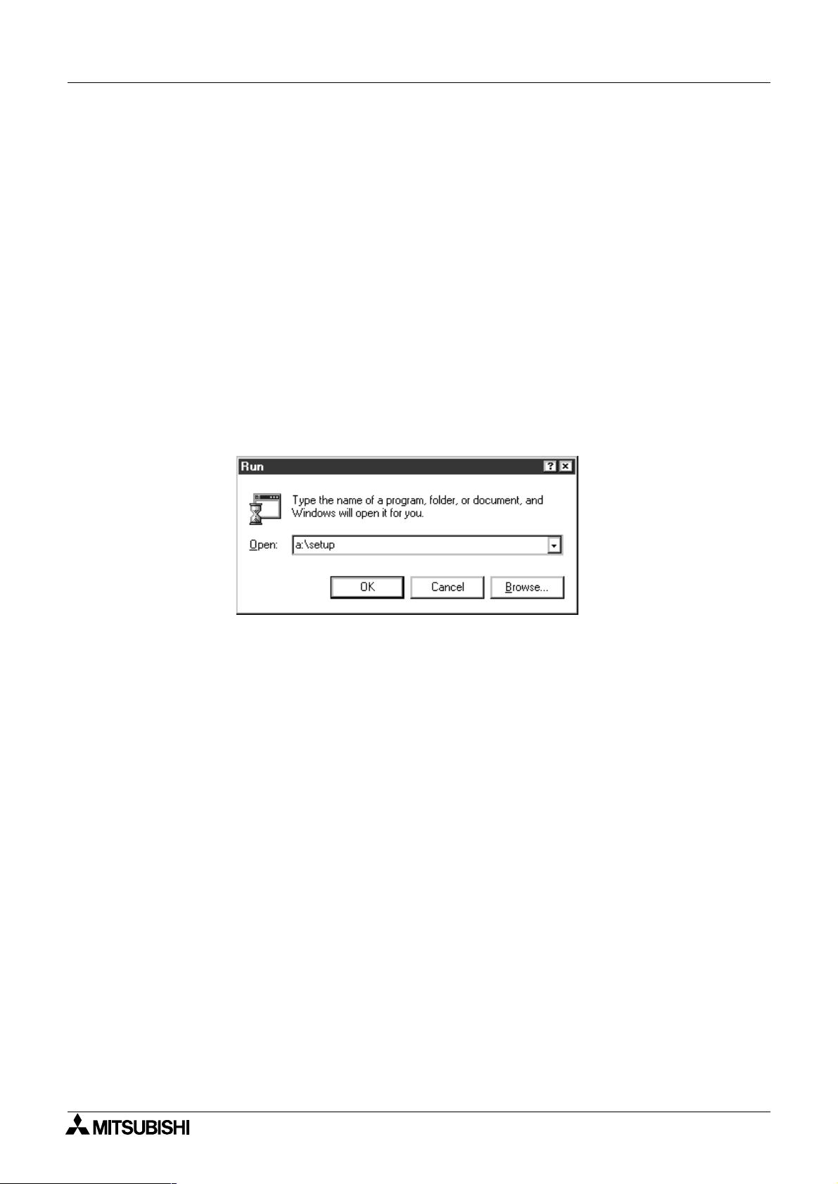
2.4.1 Starting up the setup program
It is supposed that the Windows is running.
1 ) Insert the system disk 1 into the floppy disk drive.
2 ) Click “Start” of the Windows. Place the cursor on “Save As” on the menu, and click the mouse for
execution.
3 ) Enter the drive name, colon (:) and the yen mark (\) in this order. Enter the setup file name “SETUP”.
The drive name varies depending on the model of the personal computer, the drive connected, etc. as
follows.
The first floppy disk drive is fixed to “Drive A”, and the second floppy disk drive is fixed to “Drive B”.
When the floppy disk drive used is “Drive A”, enter “a:\setup”.
Installation 2
4 ) Click the OK button or press the Enter key.
The installer is started up. Perform the operation in accordance with the instruction displayed in the
dialog box.
For example, in the case of “User information”, make sure to enter both the name and the company
name, then click the Next button.
When installation is finished, the FXDU icon is registered in the start menu program.
When setup is completed, proceed to “3. Starting up and Terminating the Program”.
2-4
Page 27
FX Series Programmable Controllers Installation 2
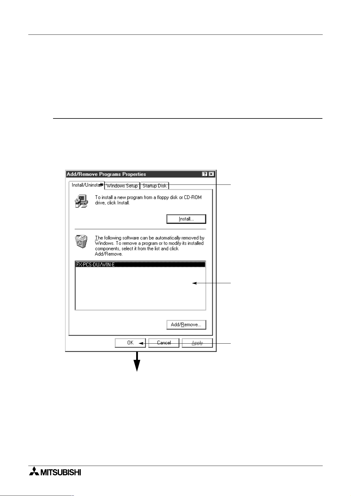
2.5 Deleting the application
The software DU/WIN can be easily deleted from the hard disk of the personal computer using the “Add/
Remove Programs” function of the Windows.
This paragraph describes the deletion procedure.
Make sure to make the backup before starting deletion when the files of screen data, external
character data, comments, etc. are included in the folder.
Deletion procedure
1 ) Double-click the “My Computer” icon.
2 ) Double-click the “Control panel” icon in the “My Computer” folder.
3 ) Double click the “Add/Remove Programs” icon.
The “Add/Remove Programs Property” dialog box is open.
4 ) Select the “Install/Uninstall”.
The list of applications registered in the box is displayed. Select “FX-PCS-DU/WIN-E” in the list.
Click the Details button.
1.Select the “Install/Uninstall”.
Deletion is executed.
2. The application list is displayed
in the box.
Select “FX-PCS-DU/WIN-E”.
3. Click it for execution.
2-5
Page 28
FX Series Programmable Controllers
2.6 Installation information
2.6.1 Installation destination directory
When the software DU/WIN is installed in the initial setting, the system program is written in the following
directory.
C:\Program Files\FX-PCS-DU-WIN-E\
\IMAGES\
Installation 2
System file list
Image library files
Table:2.2 System file list
File name Contents
FXDUWIN.EXE Execution file
FXDUWIN.HLP Help file
FXDUWIN.CNT
*1 Refer to "9.7 Image library data list"
Table:2.3 Image library file list
File name
FRAMEB**.BMP
LAMPLC**.BMP etc.
*1
2-6
Page 29
FX Series Programmable Controllers Installation 2
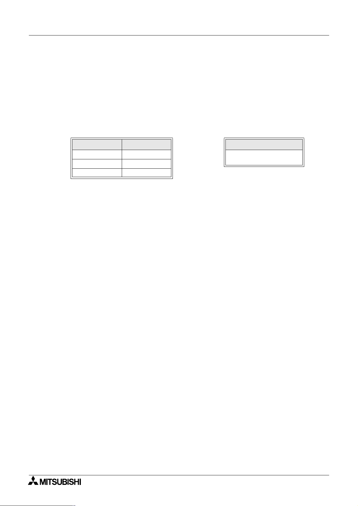
2.6.2 Upper compatibility of the drawing file
Compatibility between DOS version and Window version
A drawing file created using the FX-PCS-DU/AT-EE (DOS version) can be read using the DU/WIN software.
However, have in mind that the screen data which is newly created or edited using the DU/WIN software and
saved in a file (DUP format) cannot be read using the software of the DOS version.
To edit a file using the software of the DOS version, the screen data should be saved in the GDT format.
Though files have been created using the software of the DOS version for external characters and printers
title (document footers in the DU/WIN software), such files cannot be handled by the DU/WIN software.
However, the external character data and the printer title data can be read because they are included in the
screen data.
Files created using the software
of the DOS version
Created using
FX-PCS-DU/AT-EE
Screen data
(including external character
files and printer titles)
Sampling
Alarm history
External character file
Printer title
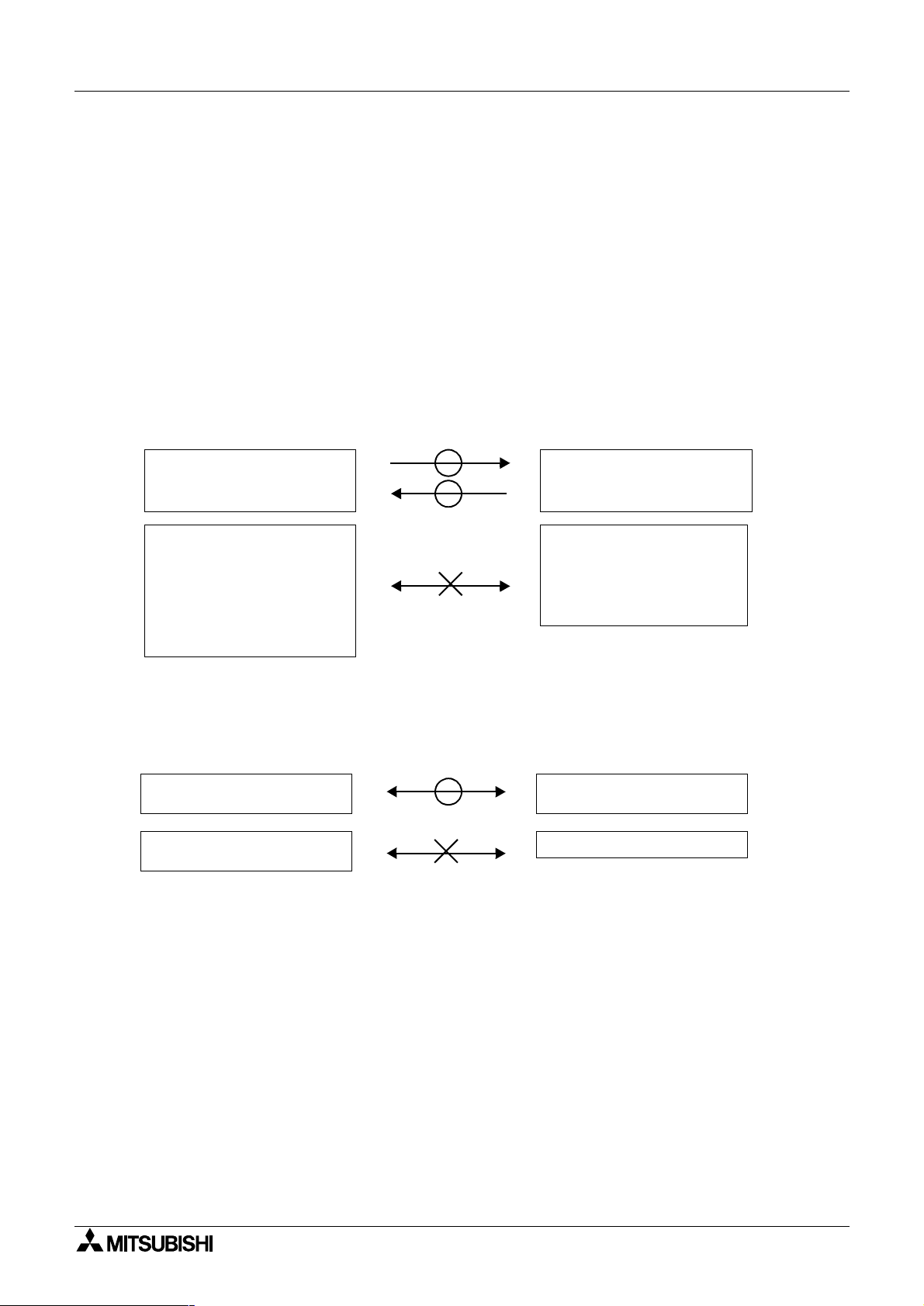
Compatibility between DU/WIN V1.
The F940GOT Series display unit added by version upgrade (to V2.0) of the DU/WIN software cannot be read
by a version former than V2.0. DU files which have been handled by V1.0 can be read.
Ver1.
×
10DU, 25DU, 30DU,
40DU-TK, 50DU-TK
××××
××××
××××
××××
××××
.GDT
.SDF
.HST
.UDL
.PTL
××××
and DU/WIN V2.
Files created using software
DU/WIN
Created using
Screen data
(including external files and
document footers)
Sampling
Alarm history
Alarm count
××××
Ver2.
×
10DU, 25DU, 30DU,
40DU-TK, 50DU-TK
××××
××××
××××
.DUP
××××
.TXT
.TXT
.TXT
Not compatible with F940GOT
Series
Compatibility when the Windows version and the DOS version are used together
When using upgraded objects and added objects of the DU and the F940GOT, make sure to use the
compatible software of the DOS version and the Windows version.
If a file is read by the software of incompatible version, errors will occur in the drawing data saved in the file.
For compatible versions, refer to "9.2 Additional functions and corresponding version of the DU".
F940GOT Series
2-7
Page 30

FX Series Programmable Controllers
Installation 2
MEMO
2-8
Page 31

FX Series Programmable Controllers
1 Introduction
2 Installation
3 Starting up and Terminating the Program
4
What You Should Know Before Starting Drawing
5 Preparation for Drawing and Basic Operations
6 Menu Bar Functions
7 Common Drawing Operations
8 Object Function Description
9 Related Information
Page 32

FX Series Programmable Controllers
Page 33

FX Series Programmable Controllers Starting up and Terminating the Program 3
3. Starting up and Terminating the Program
The software DU/WIN can be started up and terminated using the same procedures as those for a general
application. This section describes these procedures.
This section also describes the buttons and the display contents on the basic screen displayed when the
program is started up.
3.1 Starting up the program
This paragraph describes the procedure to start up icons (programs) created by installation and the DU/WIN
software.
3.1.1 Program type
The following icons are created inside the FX-PCS-DU-WIN-E folder. Each of them can be started up.
(For the operating procedure, refer to the next page.)
DU/WIN software main body
Icon name Description
FX-PCS-DU-WIN-E DU/WIN software main body
Allows to create screens for the DU.
3-1
Page 34

FX Series Programmable Controllers
3.1.2 Starting up the program
In the Windows, diversified general applications can be started up from the menu offered by clicking of the
Start button.
The software DU/WIN is also started up from this menu.
Startup procedure
1 ) Click the Start button, and point the program. The following menu is open.
2 ) Point the folder “FX-PCS-DU-WIN-E”, and click the FX-PCS-DU-WIN-E program.
1)
[Basic screen]
Starting up and Terminating the Program 3
Click here.
2)
Select the function button to be
displayed on the tool bar.
Click "File" on the tool bar.
Creates newly the screen data.
Reads the existing screen data file.
Modifies the printout form for the
printer.
Displays the list of files opened in
the past.
Terminates the software DU/
WIN.
3-2
Page 35

FX Series Programmable Controllers Starting up and Terminating the Program 3
3.2 Screen configuration of the DU/WIN
This paragraph describes how to modify the contents displayed on the screen of the software DU/WIN.
3.2.1 Basic screen
This paragraph describes the configuration of the screen displayed at first when the software DU/WIN is
started up.
The control menu box.
(Displays application icons.)
It allows selection of the
menu bar function.
Tool bar
Some functions on the
menu bar used often are
offered as buttons.
DU/WIN application window
The screen edition
window is displayed.
The comment is displayed.
It maximizes the application.
It minimizes the application.
The DU type set and the
equipment name set are
displayed.
The icons grouped on the tool bar
in accordance with the function
are displayed.
Exit
Refer to “5.Preparation for Drawing and Basic Operations”
3-3
Page 36

FX Series Programmable Controllers
3.3 Terminating the program
The following three methods are available to terminate the software DU/WIN.
This operation is equivalent to the operation in general software of the Windows..
1. Select “File” and “Exit”.
Starting up and Terminating the Program 3
Nothing is written when the
drawing data is not modified.
2. Click the control menu box of the
application window, and select
“Close”.
Unsaved file
(being edited)
Present
When the file name equivalent to that
of the file currently open is present,
the message to confirm overwrite is
displayed.
[Yes]
The file is saved with the current
file name.
[No]
The modification data is destructed, then the
program is terminated.
Not present
DU/WIN is
terminated.
[Cancel]
Execution of termination is aborted, and the
3. Click the termination button
provided in the upper right of the
application window.
When two or more application windows are open
• The software DU/WIN can open and edit two or more screen data files, and start up two or more
applications.
• When terminating the program while two or more applications are started up, make each window
active in turn, and terminate it using either of the methods above.
system returns to the application.
DU/WIN is terminated.
The drawing data file (active window) is
terminated.
3-4
Page 37

FX Series Programmable Controllers
1 Introduction
2 Installation
3 Starting up and Terminating the Program
4
What You Should Know Before Starting Drawing
5 Preparation for Drawing and Basic Operations
6 Menu Bar Functions
7 Common Drawing Operations
8 Object Function Description
9 Related Information
Page 38

FX Series Programmable Controllers
Page 39

FX Series Programmable Controllers What You Should Know Before Starting Drawing 4
4. What You Should Know Before Starting Drawing
This section describes the basic functions and the contents which you should know preliminarily before
creating the screen. Make sure to read this section thoroughly if it is your first time to create the DU screen.
4.1 Name of each object on the screen
This paragraph describes the name of each object and its function on the DU/WIN software screen.
DU/WIN application window
2) Menu bar
10) Tool bar
1) Title bar
3) Project type
display tool
9) Display
object
tool box
4)Screen list
window
5) Status bar
6) Screen window
8)Object
setting
tool box
7) Coordinates
4-1
Page 40

FX Series Programmable Controllers
Description on the object names on the screen
1 ) Title bar
Indicates the window name.
(For example, “FX-PCS-DU/WIN-E” indicates the software name, “Screen 107" indicates the screen No.,
and the following “Fx50du.gat” indicates the screen data file name.)
2 ) Menu bar %Paragraph 6.1
Displays the menu to select the command.
The menu items displayed here vary depending on the active window and the system status.
For example, when the software is started up, “File”, “View” and “Help” exclusively are displayed.
(The screen shown above indicates the case where the screen No. is selected from the screen list and
the screen No. 107 window becomes active.)
3 ) Project type display tool %Paragraph 5.2.2
Displays the DU type and the programmable controller name set on the project setting window.
4 ) Screen list window %Paragraph 5.2.5
Displays the screen No., the screen name and the memory capacity in the list to allow selection of the
screen No. to be displayed.
5 ) Status bar
Displays the message and “7) Coordinates”.
6 ) Screen window
Displays the screen selected on the screen list window as the DU screen image to allow edition.
7 ) Coordinates
Displays the mouse cursor position as the coordinates while the upper left corner of the effective area of
the DU screen image on the active “6) Screen window” is regarded as “0, 0".
8 ) Object setting tool box
Allows to modify the size, the color and the background color of the objects registered on the screen
window.
9 ) Display object tool box
Displays the objects as buttons so that they can be selected during drawing to create the screen.
10 ) Tool bar
The commands often used, the display object tool 9) and the object setting tool 8) can be displayed as
the tool buttons, and can be displayed on the tool bar and the tool box.
What You Should Know Before Starting Drawing 4
4-2
Page 41

FX Series Programmable Controllers What You Should Know Before Starting Drawing 4
4.2 Types of the DU screen and the F940GOT screen
Three types of DU/F940GOT screens are offered; the "common screen" which is always displayed, the "user
screen" which the user can create arbitrarily and the "system screen" which is built in the DU/F940GOT.
Among them, the user can register objects and create the screen for the common screen and the user
screen.
Screen list window of the FX-PCS-DU/WIN-E
Common
screen
User screen
System
screen
The screen above indicates
DU screen types
Common
screen
ABC
User screen
No.0
abc
1
System screen
Sampling
Device
monitor
n
PLC
diagnosis,
etc.
the FX-50DU-TKS-E.
Availability of screen creation
GO GO NG
Types of the DU screen
• Common screen
The registered objects are always displayed, and their functions are valid.
For example, when the user screen No. 0 is displayed in the DU while the character string “ABC” is
registered on the common screen and “abc” is registered on the user screen, “ABC” and “abc” are
displayed.
• User screen
The user can arbitrarily register the objects and create the screen to be displayed in the DU.
In addition, two or more screens can be created, cascaded via the instruction from the programmable
controller, changed over each other and displayed in the DU.
• System screen
It is preliminarily built in the DU.
“Device monitor”, “PC diagnosis”, etc. are offered, and each of them can be displayed as the user screen
so that drawing can be performed efficiently.
For example, by specifying the screen No. 500 by changing over the screen, the device monitor screen is
displayed.
However, some system screens built in the DU cannot be treated as the user screens and their display
contents cannot be modified.
The system screen names are displayed dimly in gray and cannot be selected on the Screen List
window. However, the screen No. of the changeover destination can be confirmed here.
4-3
Page 42

FX Series Programmable Controllers
Setting contents varying depending on the DU type
• On the common screen, the types of objects which can be set vary depending on the DU type.
• On the user screen, the types of objects which can be set and the number of screens vary
depending on the DU type.
They vary also depending on the programmable controller connected.
• On the system screen, the type and the number of screens vary depending on the DU type.
For the details, refer to the operation manual of the DU.
What You Should Know Before Starting Drawing 4
4-4
Page 43

FX Series Programmable Controllers What You Should Know Before Starting Drawing 4
4.3 Objects constituting the screen
The screen consists of objects classified based on the function such as characters, straight lines, rectangles, etc.
The minimum unit element classified is referred to as “object”. Objects are classified as follows.
Object classification
F940GOT (DU)
Display objects
These objects display the contents of registration of
the specified size in the specified position.
Object name: Text, Line, Box, Box (paint-over), Circle,
Circle (paint-over), Date, Time, Image
Data display objects
These objects monitor the contents of devices of the
PC of the specified size in the specified position.
1
Object name: Number*
, Bar Graph*1, Indicator,
Indicator (Text), Library Image, Indicator (Image),
Indicator (Screen), Trend Graph, Character Code,
Library Text, Circular Graph, Panel Meter, Proportional
Bar Graph, Proportional Pie Graph, Trend Graph
Programmable controller
Data is transferred to PC.
Data transfer objects
These objects turn on/off the specified device of the
PC and write the data when the specified input is
given.
Object name: Switch, Touch key, Data file transfer,
Data change, Increment, Decrement, Keyboard,
Screen changeover objects
These objects specify the screen to be
displayed next from the screen currently
displayed and set the changeover
condition.
Object name: Screen changeover
Constant write, Buzzer.
*2
Data file
The data file saves the data to
be transferred by the object
“Data File Transfer”.
Text library
The text library saves the
character strings to be displayed
by the objects “Text” and “Library
Te x t ” .
*1
In addition to the monitor function, the objects “Number”, “Bar Graph”, etc. have the function to modify the
*2
Image library
The image library saves the
graphics to be displayed by the
objects “Image” and “Library
Image”.
*2
display device data.
*2
The data file, the image library and the text library save data and character strings, and are distinguished
from objects. When the related objects are actuated, the corresponding data and character strings are
read.
*3
F940GOT only
Types of objects varying depending on the DU type
• The object names classified above indicate the case where the F940GOT is selected as the DU
model and the FX Series unit is selected as a connected PC. For the details of object names
which can be registered for each DU type, refer to "9.1.2 Object name index and applicable DU
type".
4-5
Page 44

FX Series Programmable Controllers
4.4 Functions of tools
Tools are displayed in the shape of icons buttons so that each function can be executed directly and quickly
without opening the menu. Tools are classified into groups for each function, and displayed when a target
window becomes active (by being selected).
Tools can be displayed in the two status shown below.
Stored in the menu bar
Tools are embedded in the tool bar position in the DU/WIN software, and move accordingly as the window of
the DU/WIN software is moved. When the DU/WIN software is started up, tools are stored in the menu bar.
What You Should Know Before Starting Drawing 4
Standard tools
Object setting tools
Accommodated in the tool box
Each tool is displayed on a window independent from the DU/WIN software.
Even when the window of the DU/WIN software is moved, the tool box position on the desk-top screen is not
changed.
Project type display tool
Object tools DU/WIN software
DU/WIN software
Standard tool box
Object tool box
Object setting tool box
4-6
Page 45

FX Series Programmable Controllers What You Should Know Before Starting Drawing 4
4.4.1 Tool type
The tool types and their functions are roughly described below.
Check the function of each type.
1. Standard tools
They offer the standard functions of the Windows such as creation
of a screen, cut and paste of the object data and printout of data.
2. Project type display tool
3. Object setting tools
4. Display object tools
These tools are displayed when the Screen window becomes active.
5. Object tools
These tools are displayed when the Object List dialog box becomes active.
When a project is created or when "View", "System Settings" and
"Project Setting" are selected on the menu bar, the display unit and
the connected PC selected by the displayed project setting dialog
are displayed.
For each character string, text and character code object, the
character width, the character height and the colors can be
changed.
1 ) The contents selected by the object setting tools are reflected on
dialog boxes related to character objects.
2 ) After character objects are set on the Screen window, a
Objects which are
not displayed on
the screen can be
set here.
6. Key function object tools
Objects which are not displayed
on the screen can be set here.
These tools are displayed when the Key List window becomes active.
4-7
Page 46

FX Series Programmable Controllers
4.4.2 Modifying the display layout of the tool bar
The display position and the size of the tool bar can be arbitrarily modified and the tool bar itself can be
displayed outside the application window in the same way as a general application in the Windows.
The tool bar is classified into groups in accordance with the function. The display layout can be modified by
the unit of group..
What You Should Know Before Starting Drawing 4
Tool bar area
NG GOGO
Point the mouse pointer.
Operating procedure
1 ) Display the tool box.
Move the mouse pointer to an area between the group frame and a button to point the area.
Refer to the figure above, and select carefully an appropriate area to point (= place) the mouse pointer.
2 ) Move the mouse to an arbitrary position while pressing and holding the right or left button on the mouse
(drag).
3 ) Change the tool box size.
When tools are moved to an area outside the tool bar, they are indicated
in the tool box.
To change the tool box size, point the top/bottom/right/left boarder using
the mouse. When " ↔ " or " " is displayed, drag it to realize an
arbitrary size.
Make the buttons enclosed
with the frame into one group.
Button
4 ) Store the tool box to the tool bar.
To store tools accommodated in the tool box to the tool bar, point and double-click any position of the
tool box or drag the tool box and drop it on the tool bar.
4-8
Page 47

FX Series Programmable Controllers What You Should Know Before Starting Drawing 4
4.5 Common change contents in version upgrade of DU/WIN-E
This paragraph describes the contents different from the description in the manual text due to improvement of
the operating procedures and the display contents accompanied by version upgrade of the DU/WIN-E.
→→→→
V 2.2
The operability of the screen creation software is improved.
Objects can be moved by 1 dot at a time using the cursor control keys.
In the conventional version, objects can be moved only through the mouse or coordinate inputs.
In the new version, objects selected on the screen window can be moved by 1 dot at a time.
[
↑
[
↓
[←] key: Moves the selected objects leftward by 1 dot.
[
→→→→
V 2.3
On the tool bar, "View" is changed to "View/Project".
V 2.3
] key: Moves the selected objects upward by 1 dot.
] key: Moves the selected objects downward by 1 dot.
] key: Moves the selected objects rightward by 1 dot.
→→→→
V 2.4
"Project" is added.
4-9
Page 48

FX Series Programmable Controllers
What You Should Know Before Starting Drawing 4
4.6 Before starting screen creation for F920GOT-K
When setting functions or creating screens for the F920GOT-K, refer to the description on the F940GOT in
this manual.
This paragraph describes the difference in functions between the F920GOT-K and the F940GOT.
Applicable model
F920GOT-BBD5-K-E
Description
1 ) How to read this manual
2 ) Functions provided in the F940GOT and deleted in the F920GOT-K
3 ) Difference in specifications between the F920GOT-K and the F940GOT
4 ) Colors displayed in the F920GOT-K and the screen creation software
4.6.1 How to read this manual
When reading this manual, regard "F940GOT" as "F920GOT-K".
The functions are almost similar between the F920GOT-K and the F940GOT.
The functions not provided in the F920GOT-K are described in the next paragraph.
4.6.2 Functions and objects provided in the F940GOT but not provided in the F920GOT-K
Have in mind that the following functions and settings of objects are not provided in the F920GOT-K.
Functions not provided in F920GOT-K
Table:4.1
Tool bar of DU/WIN-E Function Description Reference paragraph
Device Comments Not provided 6.4.4
View/Project
Transfer DU Sampling result cannot be read. 6.5.3
Others Sampled Data Not provided 6.6.3
Deleted objects
Table:4.2
Tool bar of DU/WIN-E Object type Description Reference paragraph
Object
Data Sampler Not provided 6.4.8
System Settings
Graph
Indicator "Output Indicator" cannot be set. 8.4.6
Touch Key Nothing 8.11
Keyboard Nothing 8.12
"Menu Key", "Bar Code Settings"
and "Color Settings" cannot be set.
"Trend Graph", "Proportional Bar
Graph", "Proportional Pie Graph"
and "Line Graph" cannot be set.
6.4.10 7) 8) 10)
8.3.2
8.3.5
8.3.6
4-10
Page 49

FX Series Programmable Controllers What You Should Know Before Starting Drawing 4
4.6.3 Difference in specifications between the F920GOT-K and the F940GOT
As to description on the specifications of the F940GOT, regard the following items as shown below.
Table:4.3
Item F920GOT-K F940GOT
Screen size 128 W × 64 H dots 320 W × 240 H dots
Memory capacity 128 kbyte 512kbyte
Number of characters 8 full-width characters × 4 lines 20 full-width characters × 15 lines
Regard the number of characters as shown above when inputting the objects "Text", "Library Text" and "Ascii"
and the text library.
4.6.4 Colors displayed in the F920GOT-K and the screen creation software
Table:4.4
F920GOT-K DU/WIN-E
White White
Blue Black
4.6.5 Changing the backlight color
The backlight color can be set in the unit of screen.
Select "Screen List" - "Screen Header", then set the backlight color in [Backlight Color].
4-11
Page 50

FX Series Programmable Controllers
What You Should Know Before Starting Drawing 4
4.7 Before starting screen creation for F930GOT(-K)
When setting functions or creating screens for the F930GOT(-K), refer to the description on the F940GOT in
this manual.
This paragraph describes the difference in functions between the F930GOT(-K) and the F940GOT.
Applicable model
F930GOT-BWD-E, F930GOT-BBD-K-E
Description
1 ) How to read this manual
2 ) Functions provided in the F940GOT and deleted in the F930GOT(-K)
3 ) Difference in specifications between the F930GOT(-K) and the F940GOT
4 ) Colors displayed in the F930GOT(-K) and the screen creation software
4.7.1 How to read this manual
When reading this manual, regard "F940GOT" as "F930GOT".
The functions are almost similar between the F930GOT(-K) and the F940GOT.
The functions not provided in the F930GOT(-K) are described in the next paragraph.
4.7.2 Functions provided in the F940GOT but not provided in the F930GOT(-K)
Have in mind that the following functions and settings are not provided in the F930GOT.
Functions not provided in F930GOT
Table:4.5
Tool bar of DU/WIN-E Function Remarks Reference paragraph
Device Comments Not provided 6.4.4
Data Sampler Not provided 6.4.8
View/Project
Transfer DU Sampling result cannot be read. 6.5.3
Others Sampled Data Not provided 6.6.3
System Settings Bar code cannot be set. 6.4.10 8)
Screen List
In the F930GOT, do not set external
keys on the key list window.
4.7.3 Difference in specifications between the F930GOT(-K) and the F940GOT
As to description on the specifications of the F940GOT, regard the following items as shown below.
Table:4.6
Item F930GOT F940GOT
Screen size 240 W × 80 H dots 320 W × 240 H dots
Memory capacity 256kbyte 512kbyte
Number of characters 15 full-width characters × 5 lines 20 full-width characters × 15 lines
Regard the number of characters as shown above when inputting the objects "Text", "Library Text" and "Ascii"
and the text library.
4.7.4 Colors displayed in the F930GOT(-K) and the screen creation software
Table:4.7
F930GOT DU/WIN-E
White White
Blue Black
4-12
Page 51

FX Series Programmable Controllers What You Should Know Before Starting Drawing 4
4.8 Cautions on screen creation in the GOT-F900 Series
This paragraph summarizes cautions on the following objects during screen creation in the GOT-F900 Series.
Have in mind the cautions.
Target models
F940WGOT-TWD-E
F940GOT-SWD-E, F940GOT-LWD-E, F940GOT-SBD-H-E, F940GOT-LBD-H-E
F930GOT-BWD-E, F930GOT-BBD-K-E
Contents
1 ) Cautions on positions in which the "Touch Key", "Number" and "Ascii" objects are arranged
2 ) Cautions on use of the touch key functions and a key code
3 ) Caution on use of "Use High quality" and "Use of 8 × 6 dot font"
4.8.1 Arrangement of "Touch Key", "Number" and "Ascii" objects
Target objects
Touch Key, Number and Ascii
Description
An object can be arranged in an arbitrary position in the unit of dot. The touch panel consists of 20 × 12 cells
each of which consists of 16 × 20 dots, and a cell is the minimum unit which recognizes touching.
If an object occupies more than a half of a cell both in the vertical and horizontal directions, the cell functions
as an effective area.
16 dots
Cell effective
as touch key
Frequent arrangement
Suppose that the character size in the vertical direction is 16 dots (H: x1) in the "Number" or "Ascii" object. If
the object is arranged so that it occupies two cells equally in the vertical direction, the object occupies 8 dots
in each of the upper cell and the lower cell. As the result, each cell is ineffective.
Ineffective
12dots
16
dots
1234
12dots
Touch key
20
dots
20
dots
20 dots
Cell ineffective
as a touch key
16dots
1234
Effective
20dots
Ineffective
4-13
Page 52

FX Series Programmable Controllers
Screen creation procedure
1 ) Use the grid display function of the DU/WIN-E software.
Set the grid to the touch key size, and arrange the object while confirming the cell position.
Make "Grid Adsorb" effective with a check mark, and arrange the object while regarding the upper left
corner of the grid (cell) as the start point.
2 ) Display the "Touch Key", "Number" and "Ascii" objects in larger size.
What You Should Know Before Starting Drawing 4
4-14
Page 53

FX Series Programmable Controllers What You Should Know Before Starting Drawing 4
4.8.2 Key code and function of touch key
Target object
Touch Key
Description
Two or more functions such as "Switch", "Change Screen" and "Data Setting" can be assigned to each touch
key. However, if a key code (except "FFFF" and "FF69") is assigned to a touch key, such functions are
disabled.
Because a key code displays the entry code registration screen (for security) or a system screen, a touch key
to which a key code (except "FFFF" and "FF69") is assigned acts as a screen changeover key.
The key code "FF69" which resets the entry code can be used together with other functions.
Key code examples
Table:4.8
Key code No. Function Function effectiveness
FFFF
FF68
FF69
Indicates that no key code is assigned.
Changes over to the entry code registration screen.
Resets the entry code.
"
"
Any other No.
For the details of key codes, refer to the F940GOT Operation Manual.
Some key codes offer the input function to enter numbers, enter alphabets (ASCII codes), move the cursor,
etc. for the "Number" object, the "Ascii" object, the alarm list and the alarm history.
Key Code
Function list
4-15
Page 54

FX Series Programmable Controllers
What You Should Know Before Starting Drawing 4
4.8.3 High-quality characters and 6
High-quality characters and 6×8-dot font are supported in products produced in March, 2001 (serial No.
13****) or later when the following OS versions are produced. They are not supported (because the font
image data is not added) even if the OS version is upgraded.
OS versions of target models
F940WGOT : Ver. 1.00 or later
F940GOT : Ver. 6.10 or later (including handy GOT)
F930GOT : Ver. 4.10 or later
F920GOT-K : Ver. 1.00 or later
Target objects
High-quality character
Number
The object above is valid when "W" is set to "4" or more and "H" is set to "2" or more in "Size".
6×8-dot font
Text, Library Text, Text Indicator, Label Indicator, Date, Time, Display Status, Alarm History, Ascii, Number
and Touch Key
The objects above are valid when "W" is set to "1" and "H" is set to "0.5" in "Size".
8-dot font
××××
4-16
Page 55

FX Series Programmable Controllers
1 Introduction
2 Installation
3 Starting up and Terminating the Program
4
What You Should Know Before Starting Drawing
5 Preparation for Drawing and Basic Operations
6 Menu Bar Functions
7 Common Drawing Operations
8 Object Function Description
9 Related Information
Page 56

FX Series Programmable Controllers
Page 57

FX Series Programmable Controllers Preparation for Drawing and Basic Options 5
5. Preparation for Drawing and Basic Options
This section describes the flow from startup of the DU/WIN software to the drawing procedure.
5.1 Screen creation procedure
When creating the screen, set the common functions, create the user screen, and set other data upon
necessity.
Start up the DU/WIN. Refer to Paragraph 3.1.
When creating the screen newly for the first time
[File] - [New]
Select the DU type and the PC connected.
Refer to Paragraph 5.2.2.
Set the control devices. Refer to Paragraph 6.4.10.
Set the common functions. Refer to Section 8.
Set the common functions valid
while any user screen is displayed.
• 25DU, 30DU, 40DU
Set the common keys.
• 40DU-TK
Set the common touch keys.
• 50DU-TK, F940(W)GOT,
F930GOT(-K), F920GOT-K
Create the screen using all
the objects on the common
setting screen.
Create the user screen.
Refer to Section 8.
Screen No.0
Create the screen by
setting each object
using the screen
edition function.
Note: The screen No. 0
shall be created in any
case.
When editing the existing screen data file
[File] - [Open]
Select the file from the list, and read it. Refer to
Paragraph 5.2.3.
Create other data. Refer to Section 6.
Create other data upon necessity.
1
n
• Create the library.
Text library (Refer to Paragraph
6.4.2)
Image library (Refer to Paragraph
6.4.3)
• Create the comment. Refer to
Paragraph 6.4.4.
• Create the alarm message. Refer to
Paragraph 6.4.5.
• Create the data file. Refer to
Paragraph 6.4.6.
Save the data often with a short interval. Refer to Paragraph 6.2.1.
Check the data (to confirm that the data set for the screen created is correct). Refer to Paragraph 6.6.1.
Transfer the screen data from the personal computer to the DU.The personal computer transfer
mode shall be preliminarily selected in the DU. Refer to Paragraph 6.5.
Display and check the screen.
Change over to the screen mode in the DU, and display the created screen.
(Some functions built in the DU/F940GOT can be displayed and checked in the test mode.)
5-1
Page 58

FX Series Programmable Controllers
5.2 Let's start to create the screen.
This paragraph describes actual cases to create the screen newly using objects such as texts and images.
The preparatory procedure for model setting, etc. to be performed after the software is started up and before
the screen is created is described here.
Cautions before creating the screen
• In the examples adopted in this paragraph, the 50DU-TK is connected. When another DU unit is
connected, some settings may be different.
Have in mind that the following items are different when another DU unit or another PC unit is
connected.
1 ) Though bit devices (X, Y, M, T, C and S) and word devices (T, C and D) are described in the
specification of a device in the examples here, available devices vary depending on a
connected PC.
2 ) The touch key setting and the ten-key display function shown here indicate the case where
the F940GOT, the 50DU-TK or the 40DU-TK is connected.
3 ) The procedure to change over the screen from a PC is partially different in another DU unit.
4 ) The vertical direction of characters and another contents can be displayed in the half-width
size only in the F940GOT, the 50DU-TK and the 25DU(-P).
5 ) In the color pallet used to specify the character color, the background color, etc., 8 colors are
displayed only when the FX-50DU-TKS-E or the F940GOT-SWD-E is selected.
Preparation for Drawing and Basic Options 5
5.2.1 Preparation for drawing (Screen window)
This paragraph describes the procedures to create the screen newly and to read and edit the existing screen
data.
1. Suppose that the basic screen (initial screen displayed when the DU/WIN software is started up) is
displayed.
3. Click to select "New".
Click "New" when creating the screen newly or when reading and editing the existing screen data.
4. The Project Settings dialog box is open.
"Project" indicates the data to be created from now on.
Paragraph 5.2.2
%
2. Click “File” on the menu bar.
When creating the screen data for the first
time, select and click “New”.
Paragraph 5.2.2
%
When editing the registered screen data,
select and click “Open . . .”.
Paragraph 5.2.3
%
When this button is clicked, the DU
list is displayed.
Select the DU unit (F940GOT-SWD
here) for which a new screen is to be
created, and click it.
5-2
Page 59

FX Series Programmable Controllers Preparation for Drawing and Basic Options 5
5. Select a PC connected to the DU.
6. Click "OK".
7. Select the screen No. to be created.
Open the Screen window using the procedure 1) or 2 ) described below.
1)
Paragraph 5.2.2
%
Paragraph 5.2.5
%
When this button is clicked, the list of
connectable units is displayed.
Select "FX Series", and click it.
2)
In the initial status, the common screen, the 0 screen (No. 0) and the system screens (No. 500 and later) are
displayed in the list.
In the F920GOT-K, the F930GOT(-K) and the F940(W) handy GOT, the system screens start from the No.
1001.
The screen No. 0 is displayed for the first time after the power is turned on. If this screen is not
created, an error occurs.
1 ) To select the screen No. 0
Point the mouse pointer, and double-click it. The DU screen image window is open.
2 ) To add a new screen
Click the “New” button. The “Screen Header” window is open.
Paragraph 5.2.5
%
Point the mouse pointer, and enter the screen
No. to be created from the keyboard.
Click the [OK] button.
5-3
Page 60

FX Series Programmable Controllers
8. The Screen window which allows to set objects is displayed.
Indicates that this is the Screen window.
Now, you can lay out the screen using objects.
The actual operating procedures to create screens using representative objects are described in "5.3 Let’s
display characters" and later paragraphs. Refer to them when using this software for the first time.
Preparation for Drawing and Basic Options 5
Project name (file name)
Indicates the screen No.
The area inside the rectangular frame is
offered as the drawing area.
List of screen creation examples using representative objects
Text....................................... 5.3 Let’s display characters
Touch key (switch)................ 5.4 Let’s turn on output using touch key switch
Number ................................5.5 Let’s display numeric value (T, C, D)
Change screen (by PLC)...... 5.6 Let’s change over screen
5-4
Page 61

FX Series Programmable Controllers Preparation for Drawing and Basic Options 5
5.2.2 Creating the screen data newly [New]
After selecting “New”, select the DU type and the equipment to be connected from each drop-down list box.
The contents set here are saved in the DU/WIN software, and automatically selected when the DU/WIN
software is started up next time.
1) Terminal
Select the DU model name.
2) PLC System
Select the PC or equipment connected to
the DU.
3) System Language
4) Character Set
Select the character font displayed on the screen.
Corresponding DU and setting list
Table:5.1
1)Terminal
FX-10DU
FX-25DU
FX-30DU
FX-40DU
FX-40DU-TK
FX-50DU-TK
FX-50DU-TKS
F940GOT-LWD
F940GOT-SWD
F930GOT-BWD
F930GOT-BWD(V)
F930GOT-BWD(H)
F940WGOT-TWD(V)
F940WGOT-TWD(H)
F920GOT-BBD5-K
MELSEC
-FX
"
"
"
"
"
"
"
"""""""" " "
"""""""" " "
"""""""" " "
"""""""" " "
"""""""" " "
"""""""" " "
"""""""" " "
"""
2) PLC System
MELSEC
-QnA,Q
MELSEC-AOMRON-CFUJI
"
"
"
"
"""
"""
-N
Select the language in which the DU
system menu is to be displayed.
AB
-SLC
500
ABMicro
Logix
SIEMENS
-S7 300
SIEMENS
-S7 200
Generalpurpose
communi-
cation
"
"
5-5
Page 62

FX Series Programmable Controllers
Preparation for Drawing and Basic Options 5
1)Terminal
FX-10DU
FX-25DU
FX-30DU
FX-40DU
FX-40DU-TK
FX-50DU-TK
FX-50DU-TKS
F940GOT-LWD
F940GOT-SWD
F930GOT-BWD
F930GOT-BWD(V)
F930GOT-BWD(H)
F940WGOT-TWD(V)
F940WGOT-TWD(H)
F920GOT-BBD5-K
2) PLC System 3) DU
FREQROL FX-GM
"" " ""
"" " ""
"" " ""
"" " ""
"" " ""
"" " ""
"" " ""
Matsushita-FP
System
Language
4) Character
Set
""
• The mark "-" in the table above indicates the function not available in the selected DU. For such a
function, the drop-down list box name is displayed in gray and cannot be selected.
• When "3) DU System Language" is set to "English", "4) Character Set" can be set to "Japanese", "West
Europe" or "Chinese (Simplified)".
The screen data created in each language can be displayed on the display screen (user screen) in the
font selected in "Character Set".
• The equipment ("2) PLC System" in the table above) connected to the DU may not be available
depending on the DU version.
• For the details, refer to the description on connection to an external equipment in the handy
manual supplied together with the DU.
• For the details of the GOT-F900 Series, refer to the description on connection in the GOT-F900
SERIES GRAPHIC OPERATION TERMINAL HANDY MANUAL (COMMON CONNECTION).
• The following graphic operation terminals are not displayed in "1) DU Type". Instead, select the
corresponding DU type shown below.
Table :5 .2
DU model name 1) Terminal
F930GOT-BBD-K-E F930GOT-BWD
F943GOT-LWD-E F940GOT-LWD
F943GOT-SWD-E F940GOT-SWD
F940GOT-LBD-H-E/F943GOT-LBD-H-E F940GOT-LWD
F940GOT-SBD-H-E/F943GOT-SBD-H-E F940GOT-SWD
When modifying the project setting later
Select "View", "System Settings" and "Project Settings", then modify the setting.
• Restriction in the F940WGOT-TWD (lateral)
In this screen creation software, all screens can be created.
However, setting of division into 2 or 3 portions is not available.
5-6
Page 63

FX Series Programmable Controllers Preparation for Drawing and Basic Options 5
5.2.3 Reading and editing the existing screen data (Open)
When “Open“ is selected, the screen data file list is displayed. Select the file name to be edited.
File read dialog box
Select the directory or drive name to be
displayed in the list.
File list display
[Open]
Executes reading.
[Cancel]
Aborts reading.
File TypeFile Name
Description on the functions of the buttons
[File Name] Enter the file name to be read using the keys or click the file name in the file list, then click
this button.
[File Type] Select the file type in accordance of the save format of the drawing data to be read.
When “All Files (*.*)” is selected, all the files saved in the directory currently selected are
displayed.
Cautions on reading the screen data
When the screen data is read from the GOT-F900 main body or an ITH file, the dialog box to select the A or
QnA Series appears (except DUP and DUA files stored using the DU/WIN-E).
Select the connected PLC Series. If a wrong Series is selected, devices may change.
When a screen data file saved in the conventional version is opened in this version, the question dialog box
shown below appears if the connected PLC Series is A, QnA or Q.
5-7
Page 64

FX Series Programmable Controllers
5.2.4 Readable files
This paragraph describes how to read a file saving the drawing data (GDT format) created by the DOS
version software of the FX-PCS-DU/AT-EE (English version for PC-AT personal computer) or a file saving the
screen data (DUP format) of this software.
By selecting “File” and “Open“, the file list display window is displayed.
By selecting “File Type”, the drawing data in accordance with the file format shown in the table below can be
selected and read.
Readable file formats
Table:5.2
File format (extender) Data type
DUP File saved by the DU/WIN (this software)
DUA File saved in the text format by the DU/WIN (this software)
ITH File saved in the Intel hex format (ROM writer)
GDT File created by the DOS version drawing software
Caution on reading an ITH file
When reading a file saved in the ITH (Intel HEX) format, check whether the project setting (DU type) selected
at the time of save is the GOT Series or the DU series, then select the Series in which the model used for
save is included.
For example, when reading a file of the screen data of the F930GOT saved in the ITH format, select "GOT
(F930GOT)" as the DU type in "New".
Preparation for Drawing and Basic Options 5
Ver2.5〜
Caution on reading a GDT file
A file saved in the GDT format was able to be read only when it was data of the data access unit (DU Series).
From Ver. 2.5, data of the graphic operation terminal (GOT-F900 Series) can be read also (as far as it is
saved using the DU/WIN-E). (Data saved using the DOS version software cannot be read.)
5-8
Page 65

FX Series Programmable Controllers Preparation for Drawing and Basic Options 5
5.2.5 Selecting the screen No. and performing additional deletion (Screen List)
When the screen is newly created or the existing screen data file is read, the screen list window is displayed.
When modifying the screen, point the screen No. in the list to be displayed using the mouse, then double-click it.
Screen list window
Screen No. display
Description on functions of the buttons
[New...] Adds the screen No.
When this button is clicked, the screen header window is displayed. Set the screen No., the
screen name, the background color and the screen protection function to be added.
[Delete] Deletes the screen No. (user screen exclusively) selected in the screen list.
When this button is clicked, the selected screen is deleted.
Pay rigid attention when using this button.
[Header] Modifies the screen No. and the screen name of the existing screen.
Screen name
Paragraph 5.2.6
%
Memory capacity of each
screen
Common screen
Screen No. 0
DU system screen
No.
The system screen No.
may be different or not be
displayed depending on
the DU.
Paragraph 5.2.6
%
[Screen] Displays the screen edition window for the screen No. selected in the screen list to allow
creation and modification of the screen display.
This button functions as if the screen No. is selected using the mouse and doubleclicked.
[Objects] Displays the object list set on the active screen selected.
The objects not displayed on the DU screen can be set by clicking this button to display the
object list window.
The objects in the list can be edited, added or deleted.
By dragging and dropping an object, the order of objects in the list can be modified.
The object displayed at the top in the object list is displayed at the bottom of the screen.
Make sure to create the screen No. 0.
When the power of the DU is turned on, the screens are displayed starting from the user screen
No. 0.
If the screen No. 0 is not present, an error occurs.
This type of error does not occur when the screen data check is performed by selecting “Other”
and “Project Check”.
Paragraph 5.2.7
%
5-9
Page 66

FX Series Programmable Controllers
Preparation for Drawing and Basic Options 5
5.2.6 Adding and changing the screen No. (Screen Header)
When the New or Header button is selected on the Screen List window, the Screen Header window is
displayed and the user can create or change the screen No. entered in "Screen No." 1).
10DU, 25DU, 30DU, 40DU, 40DU-TK and 50DU-TK
For the screen in the 10DU, refer to "8.14 Setting the objects related to the FX-10DU-E".
1)
2)
4 )3)
The functions "Protected" and "Bg" are not offered in the 10DU.
F940GOT
1)
2)
4)
5 )
6)
7)
Description on the input areas
1 ) Screen No.
When the New button is selected, an unused screen No. is automatically assigned.
When the Header button is selected, the screen header of the screen No. selected in the screen list is
displayed, and the user can select another screen No.
2 ) Screen Name
A name can be assigned to each screen. The name assigned here can be used when the screen
changeoverdestination is selected using "Call Screen" 6) or a screen changeover object.
3 ) Protected
When a screen for which "Protected" is set to ON is tried to be displayed by the screen changeover
procedure, a window is displayed to request the input of No. set by selecting "View", "System Settings"
and "Entry Code". When a code entered by the user is correct, the specified screen is displayed.
30DU, 40DU, 40DU-TK and 50DU-TK
"Protected" can be set to ON or OFF.
4 ) Bg
Select the background color of the entire screen.
The background color can be hanged also on the object setting tool screen.
5-10
Page 67

FX Series Programmable Controllers Preparation for Drawing and Basic Options 5
5 ) Security
F940GOT
When a screen for which "Protected" is set to ON is tried to be displayed by the screen changeover
procedure, the specified screen is displayed when its level is equivalent to the level of the security code
set by selecting "View", "System Settings" and "Entry Code".
To change the level, display preliminarily the password input keyboard for level change using the touch
key (to which a key code is set), change the level, then change over to the screen on which the
protection function is set.
Key code FF68
Key code FF69
When "Protected" is set to ON (A check mark is displayed in the ON status.), the level can be set within
the range of 0 to 15.
When the level is set to 0, the protection function is invalid as if "Protected" is set to OFF.
6 ) Back light color
Select the back light of the F920GOT-K between white and red.
(In other GOT-F900 units, the back light color is fixed to gray and cannot be selected.)
7 ) Call Screen
When the set screen is displayed as the base screen (which is specified by the control device "D+0"), the
first to the fourth screens are overlaid.
Control device
Common
screen
D+0
Base
screen
➀
1st
screen
D+1
Screen
➁ ➂
Screen call function
2nd
screen
3rd
screen
D+2
Screen
4th
screen
A screen on which the screen call function is set is not displayed as the screen & nor the screen '.
5-11
Page 68

FX Series Programmable Controllers
5.2.7 Adding, deleting and sorting objects (Object List)
The list of objects set on the selected screen can be displayed.In the list, objects can be edited, added and
deleted.
Objects which are not displayed on the screen can be set by displaying the Object List window.
By dragging and dropping an object, the order of the object in the list can be changed.
An object shown in an upper position in the list is displayed in a lower position on the screen.
Object List window
Screen No. Project (file name)
Object selected on the Display
Object tool box is displayed here.
List of objects currently set
Preparation for Drawing and Basic Options 5
[Insert] Allows to add any object (including undisplayed ones).
For the details, refer to the next page and "7.1 Rule on object selection".
%
[Edit] Allows to change the setting of an object selected in the object list by opening the Object
dialog box.
Instead of selecting this button, a desired object to be changed in the list can be doubleclicked to be selected.
[Delete] Deletes an object selected in the object list.
Pay rigid attention to handling of this button. Immediately when this button is clicked, the
selected object is deleted.
Addition
This paragraph describes the operating procedure to add a new object.
1. Select an object to be added from the tool bar or the object tool box. The selected object is displayed in
the area "New Object Type".
2. Click the "Insert" button. The object dialog box is open.
5-12
Page 69

FX Series Programmable Controllers Preparation for Drawing and Basic Options 5
Deletion and copy
The operating procedure is equivalent to that for objects displayed on the Screen window.
For the details, refer to "6.3.1 Deleting, transferring and copying objects (Screen window)".
Deletion, copy, edition and transfer of two or more objects
The operating procedure to select two or more objects shown in the object list is equivalent to that for objects
displayed on the Screen window.
For the details, refer to "6.3.1 Deleting, transferring and copying objects (Screen window)".
Sorting (transfer) of objects
This paragraph describes the operating procedure to change the object registration order on the Object List
window.
1. Point to select an object to be transferred.
2. Drag it to the transfer destination using the mouse.
At this time, the mouse pointer is changed from arrow-shape into document-shape.
3. Release the mouse button in the object in the transfer destination.
Make sure that the transfer destination is a line on which an object is displayed. The mouse pointer
cannot be moved to a vacant line on which no object is displayed.
The mouse pointer cannot be moved
to this vacant area.
5-13
Page 70

FX Series Programmable Controllers
5.2.8 Setting the security for system screens
The security level can be set for each system screen built in the GOT-F900.
(If the OS version of the GOT-F900 does not support this function or in the conventional specifications, the
security level set for user screens is fixed to 15.)
The security level can be set from the list on the screen list window.
Screen list window
Preparation for Drawing and Basic Options 5
From the list, select a system screen
for which the security level is to be
set.
Click the [Header] button.
Screen header
Only the "Security" field can be set.
Put the "✓" mark to "Protected".
Set the security "Level".
5-14
Page 71

FX Series Programmable Controllers Preparation for Drawing and Basic Options 5
5.3 Let’s display characters
This paragraph describes the procedure to display characters on the display screen.
(0, 0)
Example of created screen
Start point (X: 80, Y: 32)
Characters: Character
Text
Character size: W: ×2, H: ×2
Operating procedure (Display the screen window in advance while referring to Paragraph
1) Left-click "Object" on the tool bar.
Point "Text" using the mouse cursor. When the
submenu appears on the right side, point and
left-click "Text".
Submenu
(To next page)
2) Put the mouse cursor at a desired start point on
the screen window, and right-click it.
The coordinates of the mouse cursor are
displayed as "X:∗∗ Y:∗∗" at the lower right
corner of the DU/WIN-E software window.
(After creating a text, you can move it or
change its size using the Text dialog box or the
mouse.)
5-15
Page 72

FX Series Programmable Controllers
Preparation for Drawing and Basic Options 5
3) The dialog box appears.
4) The cursor is flickering in the text input area.
Paragraph 8.1.1
%
5) Input characters to be displayed.
Example: Character
Input "C", "h", "a", "r", "a", "c", "t", "e" and "r".
(To next page)
6) Set "Character Size" to "W: ×2" and "H: ×2".
5-16
Page 73

FX Series Programmable Controllers Preparation for Drawing and Basic Options 5
7) Click [OK] to close the dialog box.
5-17
Page 74

FX Series Programmable Controllers
Preparation for Drawing and Basic Options 5
5.4 Let’s turn on output using touch key switch
In some DU units, touch keys (switches) can be created at arbitrary size in arbitrary positions. In other DU
units (including the F940GOT), mechanical keys (such as ten-keys) are provided.
This paragraph describes the procedure to set a touch key which turns on the output Y0 of the PLC when
pressed.
Example of created screen
Start point (X: 80, Y: 32)
Touch Key Label: Y0 on/off
Key Type: Single frame (shaded)
Function: Switch
DU Output = Y0
Operation: Momentary
Operating procedure (Display the screen window in advance while referring to Paragraph 5.2.)
1) Left-click "Object" on the tool bar.
Point and left-click "Touch Key".
2) Put the mouse cursor at a desired start point on
the screen window, and left-click it.
The coordinates of the mouse cursor are displayed
as "X:∗∗ Y:∗∗" at the lower right corner of the DU/
WIN-E software window.
(After creating a touch key, you can move it or
change its size using the Touch Key dialog box or
the mouse.)
(To next page)
5-18
Page 75

FX Series Programmable Controllers Preparation for Drawing and Basic Options 5
3) The dialog box appears.
4) To "No.", a serial No. beginning
with "0" is automatically
assigned for identification of
each touch key.
5) In "New Object", select "Switch".
Click the new object display
area if "Switch" displayed there.
Or click the [▼] button to display
the dropdown menu, then select
"Switch" on the menu.
Paragraph 8.11
%
6) Click the [Insert] button.
Next, assign the object selected
in "New Object" to a touch key.
(To next page)
5-19
Page 76

FX Series Programmable Controllers
Preparation for Drawing and Basic Options 5
7) The Switch dialog box appears.
8) Click "Bit Device" to turn on the
radio button (●).
Input the bit device Y0 of the PLC
to turn on.
In "Operation", select "Momentary".
Click the [OK] button to close the
dialog box.
(To next page)
In the displayed current object list,
the switch function is assigned to
the touch key.
9) Input the characters to be
displayed on the touch key.
Example: Y0 on/off
In the 40DU-TK in which the
label function is not provided,
overlay the touch key and the
"Text" object.
5-20
Page 77

FX Series Programmable Controllers Preparation for Drawing and Basic Options 5
10)As the key type, select "shaded
single frame" (the second
symbol from the top).
Click the key type display area if
the shaded single frame is
displayed there.
Or click the [▼] button to display
the dropdown menu, then select
the shaded single frame.
"0" indicates the touch key No.
"∗" (asterisk) indicates that one or
more functions are set.
If no function is set, "∗" is not
displayed.
5-21
Page 78

FX Series Programmable Controllers
5.5 Let’s display numeric value (T, C, D)
This paragraph describes the procedure to display the current value and the preset value of word devices
such as timer (T), counter (C) and data register (D) of the PLC.
Example of created screen
Preparation for Drawing and Basic Options 5
(0, 0)
Start point (X: 80, Y: 32)
Number Word Device: T0
Character Size: W: ×2, H: ×2
Data Size: 16 bits
Displayed value: Preset
Operating procedure (Display the screen window in advance while referring to Paragraph 5.2.)
1) Left-click "Object" on the tool bar.
Point and left-click "Number".
(To next page)
2) Put the mouse cursor at a desired start point on
the screen window, and right-click it.
The coordinates of the mouse cursor are
displayed as "X:∗∗ Y:∗∗" at the lower right corner
of the DU/WIN-E software window.
(After creating a number, you can move it or
change its size using the Number dialog box or
the mouse.)
5-22
Page 79

FX Series Programmable Controllers Preparation for Drawing and Basic Options 5
3) The dialog box appears.
4) Input the word device.
Click the input field.
When the cursor starts to flicker,
input the word device (T0) to be
displayed or changed on the screen.
(To next page)
5) If you would like to change the
numeric value using the ten-keys,
click to check the check box to turn
on "Data Changeable".
6) Set "Displayed value" to "Preset".
Click the displayed value display
area if "Preset" is displayed there.
Or click the [▼] button to display the
dropdown menu, then select "Preset"
on the menu.
Only "Current" is available for a data
register.
Either one between "Current" and
"Preset" can be selected for a timer
and counter.
5-23
Page 80

FX Series Programmable Controllers
Preparation for Drawing and Basic Options 5
7) Input "6" to "Digits".
Click the input area for the number of
all digits. When the cursor starts to
flicker, input "6".
8) Input "2" to "Decimal Point At".
Click the input area for the number of
digits after the decimal point.
When the cursor starts to flicker,
input "2".
Concept of the number of all digits and
the number of digits after the decimal
point
Example:
Number of all digits (Digits) = 7
1234.56
Number of digits after the decimal
point (Decimal Point At) = 2
The decimal point is counted as one
digit in "Digits".
9) Set "Character Size" to "W: ×2" and
"H: ×2".
10)Click [OK] to close the dialog box.
(To next page)
5-24
Page 81

FX Series Programmable Controllers Preparation for Drawing and Basic Options 5
5-25
Page 82

FX Series Programmable Controllers
5.6 Let’s change over screen
You can change over the screen by pressing a touch key or giving a command from a connected equipment
such as PLC.
This paragraph describes the screen changeover setting procedure in the screen creation software.
Screen changeover type
Table:5.3
Typ e Set item Sequence program
1) Touch key "Touch Key" object Not required
2) Connected equipment (PLC)
3) Touch key and connected equipment (PLC)
In the set item, "Change Screen" object (without key specification) is changed to "Change Screen (by PLC)"
object.
The setting procedure for the type 3) is described below.
Example of created screen change
Preparation for Drawing and Basic Options 5
Control device
"Change Screen (by PLC)" object
"Touch Key" object
Control device
"Change Screen (by PLC)" object
Required
Required
S c r e e n N o . 0
( P a r a g r a p h 5 . 6 . 1 )
N e x t S c r e e n
M E N U
T o u c h k e y
T o u c h k e y
S c r e e n N o . 1
( P a r a g r a p h 5 . 6 . 2 )
O P E R A T I N G
P r e v i o u s S c r e e n
S c r e e n N o . 2
( P a r a g r a p h 5 . 6 . 3 )
M A N U A L M O D E
C o m m o n s c r e e n
( P a r a g r a p h 5 . 6 . 5 )
S e t " C h a n g e
S c r e e n ( b y P L C ) " .
F X S e r i e s P L C
C O M X 4
X 2
L X1 3 X 1 5
2 4 +N
X 7
X 3
X 1
IN
O U T
Y 4
Y 6
Y 1 0
Y 2
Y 5
C O M 3
Y 1 1
Y 3
X 1 0 X 1 4 X 1 6
2 4561 30
Y 1 2
Y 1 3Y 1
C o n t r o l d e v i c e ( D + 0 )
( P a r a g r a p h 5 . 6 . 4 )
7
1 61 1
1 4 1 71 510 1 2 1 3
P O W E R
R U N
W r i t e K 2 . ( P a r a g r a p h 5 . 6 . 6 )
B A T T . V
P R O G . E
72 4 5 61 30
C P U . E
1 61 1 1 51 4 1 71 0 1 2 1 3
Y 1 4
Y 1 5
¬
The later paragraphs describe the case in which the touch key changes over the screens Nos. 0 and 1, and
the FX Series PLC changes over to the screen to No. 2 using a sequence program.
List of created screens and object setting
1 ) User screen No. 0 Paragraph 5.6.1
User screen No. 1 Paragraph 5.6.2
User screen No. 2 Paragraph 5.6.3
2 ) Control device (head word device) Paragraph 5.6.4
3 ) "Change Screen (by PLC)" object on common screen Paragraph 5.6.5
4 ) Sequence program Paragraph 5.6.6
5-26
Page 83

FX Series Programmable Controllers Preparation for Drawing and Basic Options 5
5.6.1 Screen No. 0 for screen changeover
This paragraph describes the procedure to set the changeover from the screen No. 0 to the screen No. 1 by
pressing a touch key and display the text "MENU".
Example of created screen
Start point
(0, 0)
Start point (X: 100, Y: 120)
Text Character Size: W: ×4, H: ×2
Touch Key Position: X: 240, Y: 0
Size: W: 80, H: 30
Label: Next Screen
Function: Change Screen
Operating procedure (Display the screen window in advance while referring to Paragraph 5.2.)
1) Left-click "Object" on the tool bar.
Point "Text" using the mouse cursor.
When the submenu appears on the right side,
point and left-click "Text".
Submenu
2) Put the mouse cursor at a desired start point on
the screen window, and right-click it.
The coordinates of the mouse cursor are
displayed as "X:∗∗ Y:∗∗" at the lower right
corner of the DU/WIN-E software window.
(After creating a text, you can move it or
change its size using the Text dialog box or the
mouse.)
3) The dialog box appears.
4) The cursor is flickering in the text input area.
5) Input the text to be displayed.
Example: MENU
Input "M", "E", "N" and "U".
6) Set "Character Size" to "W: ×4", "H: ×2".
7) Click [OK] to close the dialog box.
Setting of text is completed.
Paragraph 8.1.1
%
5-27
Page 84

FX Series Programmable Controllers
Preparation for Drawing and Basic Options 5
1) Left-click "Object" on the tool bar.
Point and left-click "Touch Key".
2) Put the mouse cursor at a desired start point on
the screen window, and left-click it.
The coordinates of the mouse cursor are
displayed as "X:∗∗ Y:∗∗" at the lower right
corner of the DU/WIN-E software window.
(After creating a touch key, you can move it or
change its size using the Touch Key dialog box
or the mouse.)
3) The dialog box appears.
4) To "No.", a serial No. beginning with "0" is
automatically assigned for identification of each
touch key.
(Though you can change the No., the assigned
number is used as it is in this example.)
5) In "New Object", select "Change Screen".
Click the new object display area if "Change
Screen" displayed there.
Or click the [▼] button to display the dropdown
menu, then select "Change Screen" on the
menu.
(To next page)
Paragraph 8.1.1
%
5-28
Page 85

FX Series Programmable Controllers Preparation for Drawing and Basic Options 5
6) Do not set "Condition". Do not check "Bit Device".
(If "Bit Device" is clicked and the radio button is
ON, when the touch key is pressed, the screen
changes over in accordance with the setting of
the bit device of the PLC.)
7) Input "1" as the screen No. to be displayed by
screen changeover.
In the displayed current object list, the change
screen function is assigned to the touch key.
8) Input the characters to be displayed on the
touch key.
Example: Next Screen
9) As the key type, select "shaded single frame"
(the second symbol from the top).
Click the key type display area if the shaded
single frame is displayed there.
Or click the [▼] button to display the dropdown
menu, then select the shaded single frame.
(To next page)
5-29
Page 86

FX Series Programmable Controllers
Preparation for Drawing and Basic Options 5
5-30
Page 87

FX Series Programmable Controllers Preparation for Drawing and Basic Options 5
5.6.2 Screen No. 1 for screen changeover
This paragraph describes the procedure to set the changeover from the screen No. 1 to the screen No. 2 by
pressing a touch key and display the text "OPERATING".
Example of created screen
(0, 0)
Start point (X: 90, Y: 95)
Start point (X: 240, Y: 210)
Text Character Size: W: ×4, H: ×2
Touch Key Position: X: 240, Y: 210
Size: W: 80, H: 30
Label: Back
Function: Change Screen
Operating procedure (Display the screen window in advance while referring to Paragraph 5.2.)
1) Left-click "Object" on the tool bar.
Point "Text" using the mouse cursor.
When the submenu appears on the right side,
point and left-click "Text".
Submenu
2) Put the mouse cursor at a desired start point on
the screen window, and right-click it.
The coordinates of the mouse cursor are
displayed as "X:∗∗ Y:∗∗" at the lower right
corner of the DU/WIN-E software window.
(After creating a text, you can move it or
change its size using the Text dialog box or the
mouse.)
3) The dialog box appears.
4) The cursor is flickering in the text input area.
5) Input the text to be displayed.
Example: MOVING
6) Set "Character Size" to "W: ×4", "H: ×2".
7) Click [OK] to close the dialog box.
Setting of text is completed.
Paragraph 8.1.1
%
5-31
Page 88

FX Series Programmable Controllers
Preparation for Drawing and Basic Options 5
1) Left-click "Object" on the tool bar.
Point and left-click "Touch Key".
2) Put the mouse cursor at a desired start point on
the screen window, and left-click it.
The coordinates of the mouse cursor are
displayed as "X:∗∗ Y:∗∗" at the lower right
corner of the DU/WIN-E software window.
(After creating a touch key, you can move it or
change its size using the Touch Key dialog box
or the mouse.)
3) The dialog box appears.
4) To "No.", a serial No. beginning with "0" is
automatically assigned for identification of each
touch key.
(Though you can change the No., the assigned
number is used as it is in this example.)
5) In "New Object", select "Change Screen".
Click the new object display area if "Change
Screen" displayed there.
Or click the [▼] button to display the dropdown
menu, then select "Change Screen" on the
menu.
(To next page)
Paragraph 8.1.1
%
5-32
Page 89

FX Series Programmable Controllers Preparation for Drawing and Basic Options 5
6) Do not set "Condition". Do not check "Bit Device".
(If "Bit Device" is clicked and the radio button is
ON, when the touch key is pressed, the screen
changes over in accordance with the setting of
the bit device of the PLC.)
7) Input "0" as the screen No. to be displayed by
screen changeover.
In the displayed current object list, the change
screen function is assigned to the touch key.
8) Input the characters to be displayed on the
touch key.
Example: Back
9) As the key type, select "shaded single frame"
(the second symbol from the top).
Click the key type display area if the shaded
single frame is displayed there.
Or click the [▼] button to display the dropdown
menu, then select the shaded single frame.
(To next page)
5-33
Page 90

FX Series Programmable Controllers
Preparation for Drawing and Basic Options 5
5-34
Page 91

FX Series Programmable Controllers Preparation for Drawing and Basic Options 5
5.6.3 Screen No. 2 for screen changeover
This paragraph describes the procedure to display the text "MANUAL MODE" on the destination (screen No.
2) of screen changeover from the FX Series PLC.
Example of created screen
Start point (X: 32, Y: 80)
Text Character Size: W: ×3, H: ×2
Operating procedure (Display the screen window in advance while referring to Paragraph 5.2.)
1) Left-click "Object" on the tool bar.
Point "Text" using the mouse cursor.
When the submenu appears on the right side,
point and left-click "Text".
Submenu
2) Put the mouse cursor at a desired start point on
the screen window, and right-click it.
The coordinates of the mouse cursor are
displayed as "X:∗∗ Y:∗∗" at the lower right
corner of the DU/WIN-E software window.
(After creating a text, you can move it or
change its size using the Text dialog box or the
mouse.)
3) The dialog box appears.
4) The cursor is flickering in the text input area.
5) Input the text to be displayed.
Example: MANUAL MODE
6) Set "Character Size" to "W: ×3", "H: ×2".
7) Click [OK] to close the dialog box.
Setting of text is completed.
Paragraph 8.1.1
%
5-35
Page 92

FX Series Programmable Controllers
5.6.4 Setting of control device
This paragraph describes the procedure to occupy several internal contacts (M) and data registers (D) and
set the head No. of such devices for communication of diversified information between the DU and the PLC.
Functions of control devices
D U
S e t t h e h e a d o f c o n t r o l
d e v i c e s u s i n g t h e
s c r e e n c r e a t i o n s o f t w a r e .
In this example, the control devices are set to M100 and D100 using the DU/WIN-E.
D 1 0 0 , 1 0 1 , 1 0 2
R e a d t h e s c r e e n N o . t o b e
d i s p l a y e d .
D 1 0 3 , 1 0 4 , 1 0 5
W r i t e t h e c u r r e n t l y d i s p l a y e d
s c r e e n N o .
Preparation for Drawing and Basic Options 5
P L C
D 1 0 0 ¬ W r i t e s K 2 .
Control devices used for screen changeover
Table:5.5
Device No. Description of control
D100
D101
D102
D103
D104
D105
Overlay by PLC
If the overlay screens 1 and 2 are not used, write "-1" to the data register.
D 1 0 0 = K 2
Specifies screen to be displayed (base screen) using a program in PLC.
Specifies overlay screen 1.
Specifies overlay screen 2.
Currently displayed screen No. written by DU
Currently overlaying screen 1
Currently overlaying screen 2
D 1 0 1 = K 5
D 1 0 2 = K - 1
S c r e e n d i s p l a y e d i n D U
A B C D E
=
S c r e e n N o . 2
+
S c r e e n N o . 5
+
N o o v e r l a y
In specification using a
sequence program, up
to 3 screens can overlay.
A B C D E
5-36
Page 93

FX Series Programmable Controllers Preparation for Drawing and Basic Options 5
Operating procedure (Display the screen window in advance while referring to Paragraph 5.2.)
1) Left-click "View/Project" on the tool bar.
Point "System Settings" using the mouse cursor.
When the submenu appears on the right side,
point and left-click "Interface Devices".
Submenu
2) The dialog box appears.
3) The cursor is flickering in the input area.
Input a data register (D).
Example: D100
Input "D", "1", "0" and "0".
4) Left-click the input area to flicker the cursor.
Input an internal relay (M).
Example: M100
Input "M", "1", "0" and "0".
5) Click [OK] to close the dialog box.
5-37
Page 94

FX Series Programmable Controllers
5.6.5 Setting of "Change Screen (by PLC)" object
In order to change over the screen in accordance with the data register (D) specified in "Interface Devices",
you should create the "Change Screen (by PLC)" object on the user screen.
The screen to be created varies depending on the case as follows.
a ) When you would like to always change over the screen by a touch key or the PLC
b ) When you would like to always change over the screen by a touch key, but not like to change over the
screen by the PLC on the user screen
This paragraph describes mainly the setting in the case (a).
The setting procedure for the case (b) is supplemented if the procedure is different.
Example of created screen
The "Change Screen (by PLC)" object is not displayed on the user screen.
Operating procedure (Display the screen window in advance while referring to Paragraph 5.2.)
Preparation for Drawing and Basic Options 5
1) If the screen list window is not displayed, left-click "View/Project" (tool bar)-"Screen List".
Screen list window
(To next page)
5-38
Page 95

FX Series Programmable Controllers Preparation for Drawing and Basic Options 5
In the case a)
2) In the screen list, select "Common
Screen" by clicking it.
In the case b)
2) In the screen list, select a desired
screen No. by clicking it.
3) Click the [Objects] button.
Or select "Object" (tool bar)[Indicator]-[Change Screen (by
PLC)].
Proceed to 6) in the next page.
4) The dialog box appears.
5) Left-click "Object" on the tool bar.
Point "Indicator", then point and
left-click "Change Screen".
(To next page)
5-39
Page 96

FX Series Programmable Controllers
Preparation for Drawing and Basic Options 5
6) In "New Object Type" on the screen list window,
"Change Screen (by PLC)" is displayed.
7) Click the [Insert] button.
8) The Change Screen (by PLC) dialog box
appears.
9) You can set the bit device condition for screen
changeover.
In this example, click to turn on the radio button
of "Always Change".
10)You can select the method to refer to the
screen No. for screen changeover.
In this example, click to turn on the radio button
of "PLC data register" so that the word device
of the PLC set in "Interface Devices" in the DU/
WIN-E is referred to.
11)Click [OK] to close the dialog box.
Now, the "Change Screen" object is registered.
5-40
Page 97

FX Series Programmable Controllers Preparation for Drawing and Basic Options 5
5.6.6 Creation of sequence program (reference)
Create the sequence program shown below using a peripheral unit for PLC.
Device assignment table
Table:5.6
D100
Write screen No. to be displayed in sequence.
Screen No. displayed in DU (written by DU)
Control
device
D101 Overlay screen 1
D102 Overlay screen 2
D103
D104 Overlay screen 1
D105 Overlay screen 2
D0
D5 Overlay screen 1
Used as data registers to store screen
D10 Overlay screen 2
M0 to M2
M5 to M7 Overlay screen 1
Used in compare instruction (CMP) to check display screen
M10 to M12 Overlay screen 2
Base screen
Base screen
Base screen
Base screen
Sequence program
M8002
0
M8000
M1
M8000
M6
M8000
M11
D100K0MOVP
D101K-1MOVP
D102K-1MOVP
Turns ON if the displayed
screen does not agree with the
stored screen.
CMP
Turns ON if the displayed
screen does not agree with the
stored screen.
CMP
Turns ON if the displayed
screen does not agree with the
stored screen.
CMP
M0D0D103
D0
D103MOV
D100D103MOV
M5D5D104
D104MOV
D5
D101D104MOV
M10D10D105
D10
D105MOV
D102D105MOV
[Initial program]
Displays the screen No. 0 as the base screen.
Writes "-1" because overlay screens are not used.
This part is not required if overlay
screens are not used.
[Check of screen changeover by touch key]
Program for base screen
• Compares the displayed screen with the stored
screen.
• Stores the displayed screen in D0.
• Transfers the displayed screen to D100 which
specifies the screen to be displayed in the DU.
Program for overlay screen 1
• Compares the displayed screen with the stored
screen.
• Stores the displayed screen in D5.
• Transfers the displayed screen to D101 which
specifies the screen to be displayed in the DU.
Program for overlay screen 2
• Compares the displayed screen with the stored
screen.
• Stores the displayed screen in D10.
• Transfers the displayed screen to D102 which
specifies the screen to be displayed in the DU.
X000
X001
[Screen changeover area in sequence program]
D100K2MOVP
Displays the screen No. 2 when X0 of the PLC is input.
Sets the screen No. to overlay to "??".
D101K??MOVP
5-41
Page 98

FX Series Programmable Controllers
Preparation for Drawing and Basic Options 5
MEMO
5-42
Page 99

FX Series Programmable Controllers
1 Introduction
2 Installation
3 Starting up and Terminating the Program
4
What You Should Know Before Starting Drawing
5 Preparation for Drawing and Basic Operations
6 Menu Bar Functions
7 Common Drawing Operations
8 Object Function Description
9 Related Information
Page 100

FX Series Programmable Controllers
 Loading...