

Page 1

FX-485ADP COMMUNICATION ADAPTER
FX
0N-485ADP COMMUNICATION ADAPTER
USER'S GUIDE
JY992D53201C
This manual contains text, diagrams and explanations which will guide the reader in the correct installation and
operation of the FX and FX
ing to install or use these units.
Further information can be found in the FX PROGRAMMING MANUAL, FX and FX0/FX
manuals.
When the FX
USER'S GUIDE for operation.
0N-485ADP is used with the FX2N series programmable contoller, please see the FX2N-485-BD
0N, 485 communication adapters. It should be read and understood before attempt-
0N series hardware
Page 2
1
INTRODUCTION
The adapter for FX-485ADP RS485 or the adapter for FX0N-485ADP RS485 (both called 485ADP hereinafter)
is designed to link the data between PC and computer by using 485PC-IF.
(1)Data exchange by request from computer
Specified data can be exchanged by sending a request command from the computer to the PC. Except for
few functions (global function, on-demand function), the program for data link is not needed at the PC side.
●
Batch read / write of all devices (word unit, bit unit) of PC is possible. By reading out the content of each
device of the PC, the operating state can be monitored, or the data can be acquired and analyzed. Besides,
by writing data into each device, production control and production direction can be effected.
●
Remote run / stop of PC is possible. A stopped PC can be started and stopped again from the computer,
and therefore the PCs are remote controlled.
●
A batch instruction can be issued to all PCs. When one computer and plural PCs are connected, a specific
device (special auxiliary relay M8126) can be turned on or off from the computer to all PCs on the circuit.
This function is called the global function. This special auxiliary relay M8126 is an exclusive device for
global function.
(2)Data exchange by request from PC
If transmission of emergency data from the PC to the computer is necessary, the PC issues a send request
to interrupt in the computer. This function is called on-demand function, and is enabled only when the
system is composed of one computer and one PC.
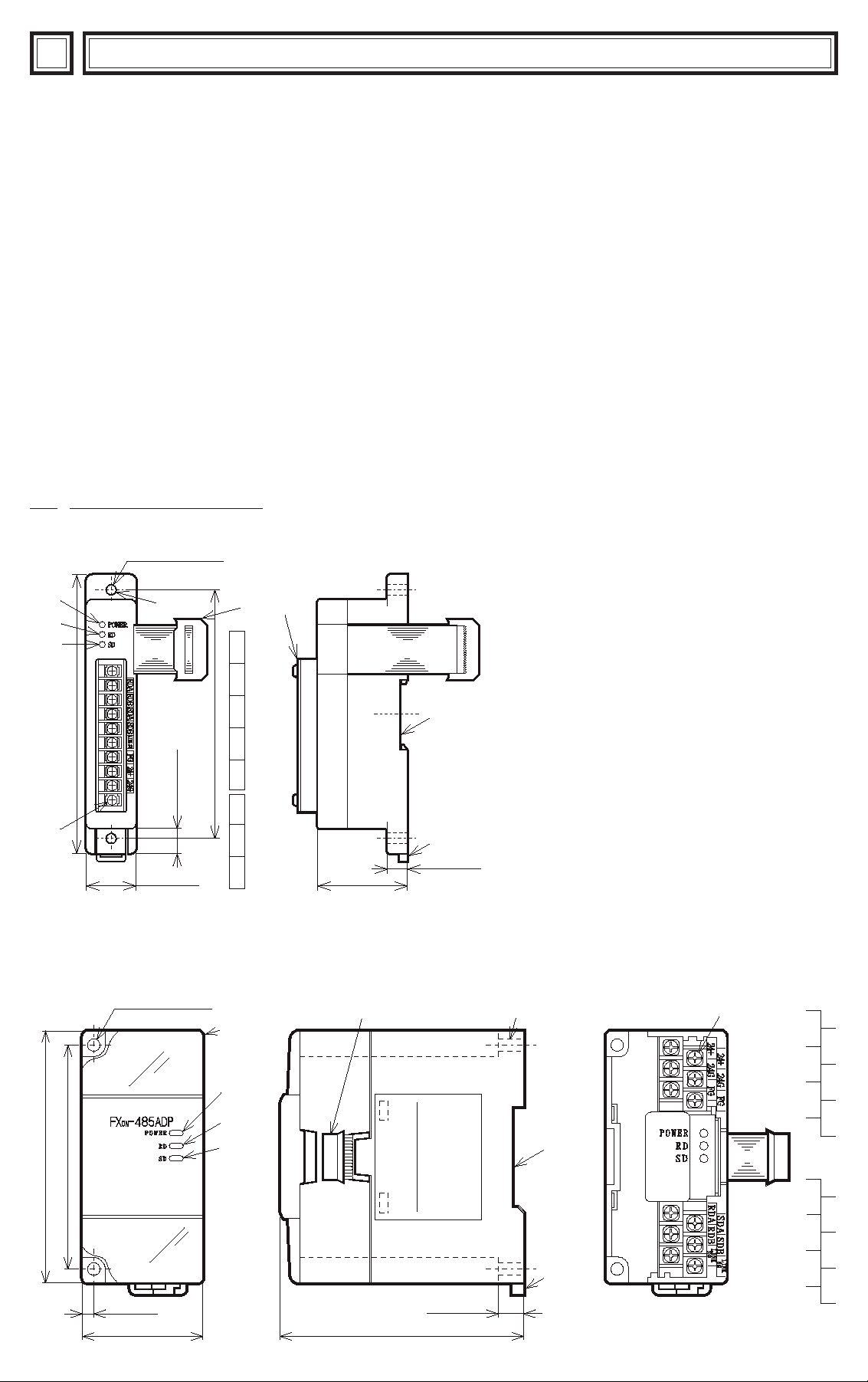
1.1 External dimensions
〈FX-485ADP〉
②
MITSUBISHI
③
④
140(5.51)
FX-485ADP
⑤
〈FX
0N-485ADP〉
2- φ4.5 (0.18)
2- φ5.5(0.22)
Mounting hole
①⑥
RDBRDA
SDBSDA
LINK SG
125(4.92)
FG
12.5(0.49)
25(0.98)
24+
24G
⑩
②
⑦
45(1.77)
⑥
Weight : Approx. 0.3 kg (0.66 lbs) Units : mm (inches)
① Direct mounting hole
lighting while power is correctly
supplied.
lighting while receiving data.
lighting while sending data.
⑧
⑨
10(0.39)
② Power LED ···
③ RD LED ·······
④ SD LED ·······
⑤ Terminal screws (M3 (0.12))
⑥ Extension cable
⑦ Terminal cover
⑧ Groove for mounting DIN rail (DIN rail width :
35 (1.38))
⑨ Hook for mounting DIN rail
⑩ Top cover
Weight : Approx. 0.3 kg (0.66 lbs) Units : mm (inches)
①
⑤
24G24+ FG
24G24+ FG
90(3.54)
80(3.15)
4(0.16)
43(1.69)
③
④
FX0N-485ADP
87(3.43)
9(0.35)
⑧
⑨
485ADP
RDA RDB
SDA SDB
LINK
SG
LINK
SG
Page 3
,,,,
,,,,
,,
,,
,,
,,
,,,,
,,,,
,,
,,
,,
,,
,,
,,
,,
,,
,,,,
,,,,
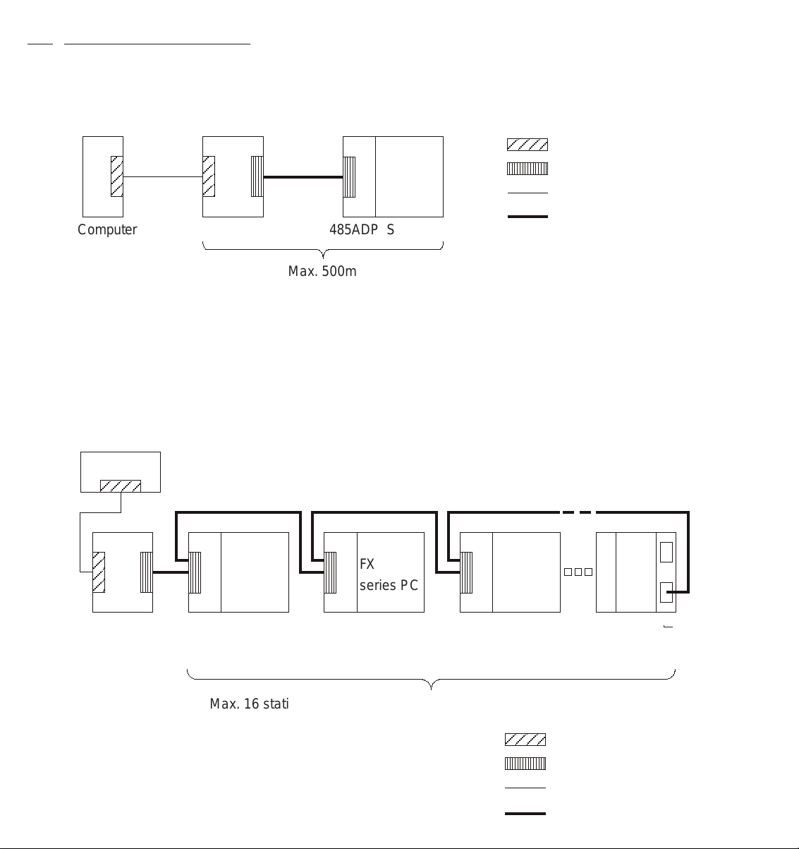
1.2 System configuration
The system configuration of computer and PC is either 1 : 1 or 1 : n, and for communication with the computer,
the RS-485 or RS-422 is used.
(1) Computer and PC by 1 : 1 configuration
: RS-232C interface
FX,FX2C
series PC
: RS-485 interface
: RS-232C cable
Computer 485ADP Station No.0
485PC-IF
Max. 500m
(2) Computer and PC by 1 : n configuration
In this case, the number of link stations is 16 PCs at maximum for one computer, including the FX series
PCs and A series PCs. Such system of data exchange with plural PCs with one computer is called the
multi-drop link system.
Computer
A
: RS-422 or RS-485 cable
FX
series PC
485PC-IF Station
485ADP 485ADP 485ADP Station
No.0
FX
series PC
Station
No.1
FX
series PC
No.2
CPU
series
PC
Station
No.15
↑
Computer
link unit
Max. 16 stations including A series PCs (total extension distance 500m)
: RS-232C interface
: RS-485 interface
: RS-232C cable
: RS-422 or RS-485 cable
Page 4
1.3 Applicable PCs
For setting up the system, the 485ADP can be connected to the following PCs.
FX
0N-485ADP
FX-485ADP
PC series
0N
FX
FX , FX2C
PC version
Ver. 1.20 or later
Ver. 3.30 or later
Exclusive protocol format 1 and format 4 are supported.
Exclusive protocol format 1 and format 4 are supported.
Remarks
As for exclusive protocol formats (1, 4) , see the 485PC-IF manual.
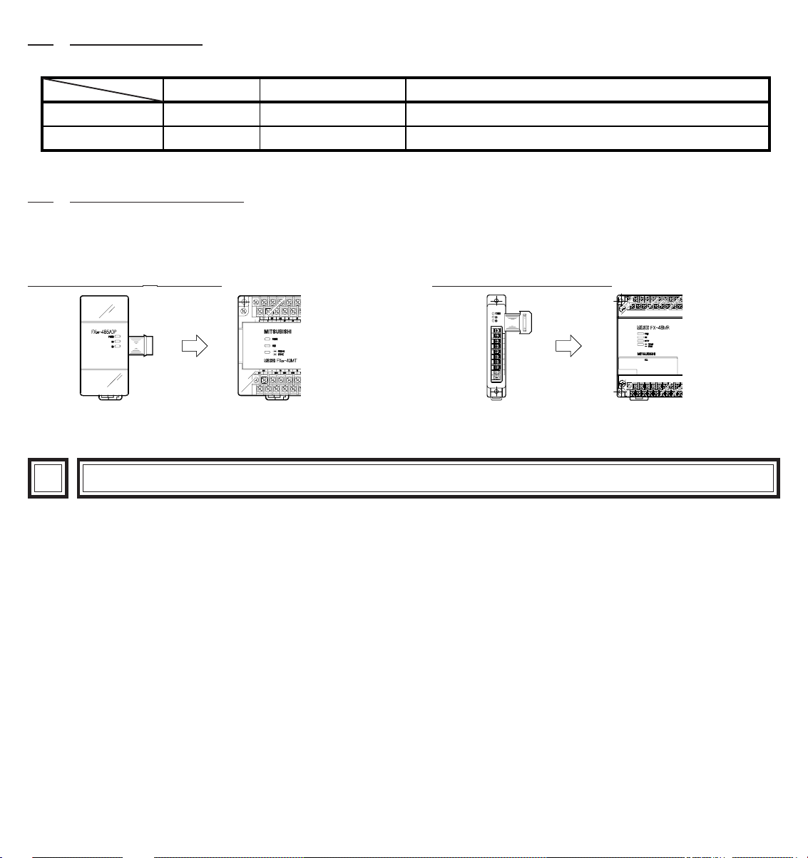
1.4 Connection with PC
For connection with the PC, connect the serial port provided at the left side facing the PC basic unit and the
extension cable of the 485ADP. It must be noted however that only one special adapter (FX-8AV, FX-232ADP,
etc.) such as 485ADP can be connected to the PC.
In the case of FX-485ADPIn the case of FX0N-485ADP
MITSUBISHI
RDA
RDB
SDASDBLINK
SG
FG
24+
24G
FX-485AD P
2
WIRING
The connecting method with the 485PC-IF is available in two-pair wiring and one-pair wiring, which may be
used as follows. As for connection of the 485PC-IF and computer, see the 485PC-IF manual.
●
Two-pair wiring is required when :
① The RS-422 device is incorporated in the system configuration.
② A high speed response is required (message waiting time is desired to be less than 70 ms).
*
③ The on-demand function is used (however, the system configuration must be 1 : 1).
④ Adding to a system already using two-pair wiring.
*See the 485PC-IF manual.
●
One-pair wiring is required when :
① Adding to a system already using one-pair wiring.
② The system configuration is standardized to RS-485 devices, and two-pair wiring is not needed.
Page 5

2.1 Examples of two-pair wiring (for RS-422 circuit)
(1) When connecting one computer and one PC
485PC-IF
Signal name
SDA
SDB
RDA
RDB
LINK SG
Grounding
resistance of
100 Ω or less
Cable connection and signal direction
*1
R
*1
R
FG
DC24V
FX base unit
24V
24G
485PC
Signal name
RDA
*1
R
RDB
SDA
∗1
R
SDB
LINK SG
*2
*3
*3
Application
Reception data
Reception data
Transmission data
Transmission data
Signal ground
Frame ground
Power supply terminal
Power supply terminal
(2) Computer and PCs in 1 : n connection ( n has a maximum value of 16 ).
The terminal lagout shown is diagrammatic only. As for 485ADP, see chapter 1, and as for 485PC-IF,
and computer link unit for A series PC, see the individual manuals.
Computer 485ADP485PC-IF 485ADP
Station
No. 1
SDA
SDB
RDA
RDB
LINK
SG
*2*2
FG
SD
RD
SD
RD
Station
*1
R
SDA
SDB
*1
R
RDA
RDB
LINK
SG
No. 0
SDA
SDB
RDA
RDB
LINK
SG
FG
Computer link unit
of A series PCs
Station
No. 15
SDA
SDB
RDA
RDB
SG
*2
FG
*1
R
*1
R
*1 R is the terminating resistance. Connect the terminating resistance (330Ω) between terminals
SDA and SDB , and terminals RDA and RDB . For details see section 2.3.
*2 Connect terminal FG to earth terminal of the PC main body grounded with resistance of 100
Ω or less. However, as for the computer link unit of the A series PC, see the manual of the computer
link unit.
*3 The 24V DC power requirement can be taker from the service power supply of the PC.
Page 6

2.2 Examples of one-pair wiring (for RS-485 circuit)
(1) When connecting one computer and one PC
485PC-IF
Signal name
SDA
SDB
RDA
RDB
LINK SG
Grounding
resistance of
100 Ω or less
Cable connection and signal direction
*1
R
DC24V
FX base unit
485ADP
Signal name
*1
R
LINK SG
FG
24V
24G
*2
*3
*3
RDA
RDB
SDA
SDB
Application
Reception data
Reception data
Transmission data
Transmission data
Signal ground
Frame ground
Power supply terminal
Power supply terminal
(2) Computer and PCs in 1 : n connection ( n has a maximum value of 16 ).
The terminal lagout shown is diagrammatic only. As for 485ADP, see chapter 1, and as for 485PC-IF, and
computer link unit for A series PC, see the individual manuals.
485ADP485ADP485ADPComputer 485PC-IF
SDA
Station
No. 0
SDA
Station
No. 1
SDA
Station
No. 15
SDA
SD
RD
SD
RD
SDB
*
1
R
RDA
RDB
LINK
SG
SDB
RDA
RDB
LINK
SG
FG
SDB
RDA
RDB
LINK
SG
*2*2
FG
SDB
RDA
RDB
LINK
SG
*2
FG
*1
R
*1 R is the terminating resistance. Connect the terminating resistance (110 Ω) between terminals
RDA and RDB . For details see section 2.3.
*2 Connect terminal FG to earth terminal of the PC main body grounded with resistance of 100
Ω or less. However, as for the computer link unit of the A series PC, see the manual of the computer
link unit.
*3 The 24V DC power requirement can be taker from the service power supply of the PC.
Page 7

2.3 Terminating resistances
The terminating resistances are resistances connected between terminals SDA and SDB, and between terminals
RDA and RDB at both end stations of the circuit (or the interface when an interface such as 485PC-IF is used
at both end stations), when connecting with the RS-485 or RS-422 circuit. For connection examples, see
section 2.1 and 2.2.
Classification of terminating resistances
In this product, two sets of terminal end resistances (330Ω✕2, 110 Ω ✕ 1) are packaged, and the terminating
resistances to be connected differ as shown below depending on the circuit being used.
●
When communicating with the RS-422 circuit, connect the resistances of “330Ω 1/4W ” as the terminating
resistances.
●
When communicating with the RS-485 circuit, connect the resistances of “110 Ω 1/2W ” as the terminating
resistances.
〈330Ω〉
BrownOrange Brown Orange
Two-pair wiring
〈110Ω〉
One-pair wiring
SDA
SDB
RDA
RDB
Terminating resistance
(330Ω)
Terminating resistance
(330Ω)
SDA
SDB
RDA
RDB
Terminating resistance
(110Ω)
2.4 Cautions for wiring
As one of the conditions for exhibiting the function of the 485ADP sufficiently and building up a reliable system,
external wiring resistant to noise is essential. Cautions for external wiring are given below.
(1) In this system, the data is read or written (turned on or off by force) while the PC is operating. Accordingly,
if abnormal data is written into the PC due to effect of noise, the PC may malfunction, leading to machine
trouble or accident, and therefore the following cautions should be strictly observed.
●
Never lay near or bundle together with the main circuit, high voltage line or load line. Or effects of noise or
surge induction may be serious. Keep at least a safe distance of over 100 mm from these lines.
●
Ground the shield wire or shield of shield cable at one point at the PC side. Never ground commonly with
high voltage line.
(2) Terminals screws of terminal block for RS-485 are M3 threaded. Therefore, connect wiring by fitting a
crimped terminal suited to the terminal screws (see below) to the cable.
6.2 mm
(0.24 inches)
or less
M3
threads
6.2 mm
(0.24 inches)
or less
M3
threads
(3) Tightening torque of terminals is 0.5 to 0.8 N·m (5 to 8 kgf·cm). Screw terminals must be secure enough to
prevent a loose connection from causing a malfunction.
Page 8

3
SPECIFICATIONS
Environmental specifications
Operating ambient temperature
Humidity no condensation
Vibration resistance
Shock resistance
Noise immunity
Dielectric withstand voltage
Insulation resistance
Ground
Operating ambience
0 to 55°C, storage temperature -20 to 70°C
35 to 85% RH (No condensation)
Conforming to JIS C 0911. 10 to 55 Hz, 0.5 mm (max. 2G), 2 hr each in 3 axes; however, 0.5G
when mounting DIN rail.
Conforming to JIS C 0912. 10G, 3 times each in 3 axes
Noise voltage 1000V p-p, noise width 1µsec, period 30 to 100 Hz, by noise simulator.
500V AC, 1 min
500V DC, 5 MΩ by Megger
Grounding resistance of 100Ω or less (class 3)
Free from corrosive gases, minimal dust.
Between all terminals in batch and FG terminal
Power source specification and type of isolation
Supply voltage
Current consumption
Type of isolation
5V DC (supplied from PC), 24V DC ±10%
External power supply : 24V DC, max. 50 mA
Internal power supply from PC : 5V DC, max. 30 mA
Power source is isolated by transformer ; PC and communication signal lines are isolated by
photo coupler .
Performance specification
●
Transmission specification * For detail of Special D8120, D8121, and D8129, see the 485PC-IF manual.
Item
Interface
Communication method
Synchronization method
Transfer speed (bps)
Start bit
Data format
Error
detection
Transfer control procedure
Access cycle
Circuit configuration (computer : PC)
ransfer
distance
Station numbers
Time-out judging time
(Special D8129 )
Data bit
Vertical parity bit
Stop bit
Parity check
Sum check
RS-485, RS-422
RS-232C
FX0N
FX, FX2C
Conforming to RS-422 / 485.
Exclusive protocol, half-duplex communication system
Start-stop synchronous system
300,600,1200,2400,4800,9600,19200
1
7 or 8
1 or none
1 or 2
Odd / even / none
Yes / no
Protocol format 1 or format 4
One request is processed at the time of END processing of sequence program. Therefore,
access cycle is one scan time.
1 : 1 or 1 : n (n = 0 to 15, max. 16 stations)
Total extension within 500 m
Within 15 m
0 to 15 (set by Special D8121 )
1 to 255 (10 to 2,550 ms) ; however, setting of “0” hrenders 100 ms.
1 to 3,276 (10 to 32,760 ms) ; however, setting of “0” hrenders 100 ms.
Specifications
The communication format of the PC is set using
special D8120.
*
Page 9

4
COMMAND AND DEVICE RANGE
4.1 Computer commands
Command
Symbol ASCII code
BR
42H,52H
WR
BW
WW
GW
BT
WT
RR
RS
PC
TT
57H,52H
42H,57H
57H,57H
42H,54H
42H,54H
52H,52H
52H,53H
52H,43H
47H,57H
54H,54H
To read out on/off state of bit device in batch in the unit of 1
point.
To read out on/off state of bit device in batch in the unit of
16 points.
To read out numerical data stored in word device in batch in
the unit of 1 point.
To write on/off state into bit device in batch in the unit of 1
point.
To write on/off state into bit device in batch in the unit of 16
points.
To write numerical data into word device in batch in the unit
of 1 bit.
To specify bit device at random in the unit of 1 point, and
set/reset by force.
To specify bit device at random in the unit of 16 points, and
set/reset by force.
To specify word device at random in the unit of 1 point, and
write data by force.
To remote-run the PC.
To remote-stop the PC.
To read out the type name of PC.
To turn on/off global signal (special auxiliary relay M8126 in
FX series) to all PCs connected to computer link.
To transmit the data received from computer directly back
to the computer.
Function
* Counter except for high speed counter, 32-bit counter (C200 to C255).
Objective
device symbol
X,Y,M,S,T,C
X,Y,M,S
T,C,D
X,Y,M,S,T,C
X,Y,M,S
T,C,D
X,Y,M,S,T,C
X,Y,M,S
*
T,C , D
Special
auxiliary
relay M8126
Number of processing points
done by one communication
FX, FX
2CFX0N
54 points
13 words,
208 points
13 points
46 points
10 words,
160 points
11 points
10 points
6 words,
96 points
6 points
256 points
32 words,
512 points
64 points
160 points
10 words,
160 points
64 points
20 points
10 words,
160 points
10 points
1 points 1 points
254 characters25 characters
4.2 PC commands
The command to be effected from the PC is the on-demand command only. This command can be used only
when the system configuration is 1:1. In this on-demand command, the content of the data register specified at
the PC side is transmitted to the computer side from the PC side. The maximum number of points of the data
register that can be transmitted as follows.
PC series
0N
FX
FX , FX2C
Max. number of points
13 words
64 words
4.3 Device range
Device
Input relay
Output relay
Auxiliary relay
State
Special auxiliary relay
Bit device
Timer contact
Counter contact
Timer present value
Counter present value
Data register
File register
Word device
RAM file register
Special data register
( )
X
( )
Y
( )
M
( )
S
( )
M
( )
T
C
( )
( )
T
C
( )
( )
D
( )
D
( )
D
( )
D
Device number range (characters)
FX
0N series PC
X0000 ~ X0177
Y0000 ~ Y0177
M0000 ~ M0511
S0000 ~ S0127
M0000 ~ M8254
TS000 ~ TS063
CS000 ~ CS031
CS235 ~ CS254
TN000 ~ TN063
CN000 ~ CN031
CN235 ~ CN254
D0000 ~ D0255
D1000 ~ D2499
D8000 ~ D8255
FX
, FX2C series PC
X0000 ~ X0337
Y0000 ~ Y0337
M0000 ~ M1535
S0000 ~ S0999
M8000 ~ M8255
TS000 ~ TS255
CS000 ~ CS255
TN000 ~ TN255
CN000 ~ CN255
D0000 ~ D0999
D1000 ~ D1999
D6000 ~ D7999
D8000 ~ D8255
Decimal/Octal
expression
Octal
Decimal
As for timer and counter, it must be noted
that the character symbols differ as follows
between the bit device and word device.
Timer
Counter
Bit device (contact)
TS
CS
Word device (present value)
TN
CN
Page 10

5
In case of trouble, check the following points, and remedy according to the troubleshooting guide in the 485PCIF manual.
(1) Power LED
Lit
Otherwise
(2) As for SD LED, RD LED, check and remedy according to the troubleshooting guide in the 485PC-IF manual.
: The extension cable is normally connected to the PC.
: The extension cable is not connected correctly, or external 24 V DC power supply is not func-
tioning correctly. Check and connect correctly.
DIAGNOSTICS
Page 11

6
START UP PROCEDURE
Prior to start of operation, follow the procedure below. As for detail of procedure, see the 485PC-IF manual.
Determine system configuration
Setting of transfer specification
(1)
(D8120)
Specification of data length
•
Specification of parity
•
Specification of stop bit
•
Specification of transfer speed
•
(baud rate)
Specification of sum check
•
Specification of transfer
•
procedure (exclusive protocol)
Setting of station number (D8120)
(2)
Setting of time-out check time
(3)
(D8129)
Creation of program at computer side
External wiring
······
See section 1.2.
For each item of the communication format e. g., station number, time-
······
out check time, please see the 485PC-IF manual.
When using the FX
0N series PC, be sure to turn on the special auxiliary
relay M8120 because special data registers D8120, D8121, and D8129
are reserved.
When the special auxiliary relay M8120 is in an ON state, it must be
noted that the backed up data registers D254, D255 become general
data registers.
······
Create communication program on the computer by using BASIC or
the similar programming tools.
······
See section 2.1 and 2.2.
Connection of terminal end resistance
Loop test
Creation of sequence program for data
transmission and reception
Operation
See section 2.3.
······
······
Execute loop test, and confirm data exchange.
For details see the 485PC-IF manual.
When using on-demand function or global function, the sequence
······
program for transmission and reception is required at the PC side.
For details see the 485PC-IF manual.
Page 12

Guidelines for the safety of the user and protection of
the FX-485ADP, FX0N-485ADP communication adapter
●
This manual has been written to be used by trained and competent personnel. This is defined by
the European directives for machinery, low voltage and EMC.
●
If in doubt at any stage during the installation of the FX-485ADP, FX0N-485ADP always consult a
professional electical engineer who is qualified and trained to the local and national standards. If in
doubt about the operation or use of the FX-485ADP, FX
Mitsubishi Electric distributor.
●
Under no circumstances will Mitsubishi Electric be liable or responsible for any consequential
damage that may arise as a result of the installation or use of this equipment.
●
All examples and diagrams shown in this manual are intended only as an aid to understanding the
text, not to guarantee operation. Mitsubishi Electric will accept no responsibility for actual use of
the product based on these illustrative examples.
0N-485ADP please consult the nearest
JY992D53201C
Manual number
Manual revision
Data
HEAD OFFICE : MITSUBISHI DENKI BLDG MARUNOUCH TOKYO 100 TELEX : J24532 CABLE MELCO TOKYO
HIMEJI WORKS : 840, CHIYODA CHO, HIMEJI, JAPAN
: JY992D53201
: C
: AUGUST 1997
Effective AUG. 1997
Specifications are subject
to change without notice.
 Loading...