

Mitsubishi FX1N-60MR-ES/UL, FX1N-14MT-ESS/UL, FX1N-14MR-DS, FX1N-14MT-DSS, FX1N-24MR-DS Hardware Manual
...
FX
HARDWARE MANUAL
1N
SERIES PROGRAMMABLE CONTROLLERS

FX1N Series Programmable Controllers
Foreword
• This manual contains text, diagrams and explanations which will guide the reader in the correct installation
and operation of the FX
attempting to install or use the unit.
• Further information can be found in the FX Series Programming Manual II.
1N
Series Programmable Controllers. It should be read and understood before
• If in doubt at any stage of the installation of an FX
professional electrical engineer who is qualified and trained to the local and national standards which apply to
the installation site.
• If in doubt about the operation or use of FX1N Series Programmable Controller please consult the nearest
Mitsubishi Electric distributor.
• This manual is subject to change without notice.
1N
Series Programmable Controller always consult a

FX1N SERIES PROGRAMMING CAUTION
Thank you for buying The Mitsubishi FX1N series controller.
Please note the following.
Notes: Block Move instruction
Applicable PLC: FX1N Ver 1.00-2.10
Applicable instructions: BMOV, BMOVP(FNC15)
If the file register parameter setting and the registers D8000-D8225 are used as the
destination devices for the BMOV(BMOVP) instruction, program steps or file register data may
be lost or damaged. All other data registers can be used safely for BMOV(BMOVP) instruction
destination registers.
Program example
Problem OK
M8002
(S·) (D·) n
BMOV D8140 K2
D D
M8002
(S·) (D·)
DMOV D8140


FX1N Series Programmable Controllers
FX
Series Programmable Controllers
1N
Hardware Manual
Manual number : JY992D89301
Manual revision : L
Date :
May 2006
This manual confers no industrial property rights or any rights of any other kind, nor does it confer any patent
licenses. Mitsubishi Electric Corporation cannot be held responsible for any problems involving industrial
property rights which may occur as a result of using the contents noted in this manual.
i

FX1N Series Programmable Controllers
Guidelines for the safety of the user and protection of the FX1N.
This manual provides information for the installation and use of the FX1N. The manual has
been written to be used by trained and competent personnel. The definition of such a person
or persons is as follows;
a) Any engineer who is responsible for the planning, design and construction of automatic
equipment using the product associated with this manual should be of a competent
nature, (trained and qualified to the local and national standards required to fulfill that
role). These engineers should be fully aware of all aspects of safety with regards to
automated equipment.
b) Any commissioning or service engineer must be of a competent nature, trained and
qualified to the local and national standards required to fulfill that job. These engineers
should also be trained in the use and maintenance of the completed product. This
includes being completely familiar with all associated documentation for the said product.
All maintenance should be carried out in accordance with established safety practices.
c) All operators of the completed equipment (see Note) should be trained to use that
product in a safe manner in compliance to established safety practices. The operators
should also be familiar with documentation which is associated with the operation of the
completed equipment.
Note :
The term ‘completed equipment’ refers to a third party constructed device which
contains or uses the product associated with this manual.
ii

FX1N Series Programmable Controllers
Note’s on the symbols used in this manual
At various times through out this manual certain symbols will be used to highlight points of
information which are intended to ensure the users personal safety and protect the integrity of
the equipment. Whenever any of the following symbols are encountered, its associated note
must be read and understood. Each of the symbols used will now be listed with a brief
description of its meaning.
Hardware warnings
1) Indicates that the identified danger
WILL
2) Indicates that the identified danger could
cause physical and property damage.
POSSIBLY
cause physical and property damage.
3) Indicates a point of further interest or further explanation.
Software warning
1) Indicates special care must be taken when using this element of software.
2) Indicates a special point which the user of the associate software element should be aware
of.
3) Indicates a point of interest or further explanation.
iii

FX1N Series Programmable Controllers
• Under no circumstances will Mitsubishi Electric be liable or responsible for any consequential
damage that may arise as a result of the installation or use of this equipment.
• All examples and diagrams shown in this manual are intended only as an aid to understanding the
text, not to guarantee operation. Mitsubishi Electric will accept no responsibility for actual use of the
product based on these illustrative examples.
• Please contact a Mitsubishi Electric distributor for more information concerning applications in life
critical situations or high reliability.
iv

FX1N Series Programmable Controllers
No
te Concerning
the CE Marking
This document does not guarantee that a mechanical system including this product will comply
with the following standards. Compliance to EMC directive and LVD directive of the entire
mechanical system should be checked by the user / manufacturer.
For more details please contact the local Mitsubishi Electric sales site.
EMC
The following products have shown compliance through direct testing (of the identified
standards below) and design analysis (through the creation of a technical construction file) to
the European Directive for Electromagnetic Compatibility (89/336/EEC) when used as directed
by the appropriate documentation.
Refer to a manual or related material of each product other than the following.
Type : Programmable Controller (Open Type Equipment)
Models : MELSEC FX
from March 1st, 2000 FX
from June 1st, 2000 FX
from December 1st, 2000 FX
1N
series manufactured
1N
-232-BD FX1N-485-BD FX1N-422-BD
FX1N-8AV-BD FX1N-CNV-IF FX1N-5DM
FX1N-EEPROM-8L
1N
-
1N
-
Where
MR-ES/UL
MR-DS FX1N-
indicates:14,24,40,60
MT-DSS
v

FX1N Series Programmable Controllers
from June 1st, 2001 FX1N-4EX-BD FX1N-2EYT-BD FX1N-2AD-BD
from July 1st, 2001 FX
FX
1N
-1DA-BD
1N
-
MT-ESS/UL Where
indicates:14,24,40,60
Models : MELSEC FX
from November 1st, 1995 FX
from February 1st, 1996 FX
from April 1st, 1996 FX
from May 1st, 1996 FX
from July 1st, 1996 Harmonized Products
Models : MELSEC FX
0N
series manufactured
0N
-40ER-ES, FX0N-8EX-ES, FX0N-8EYR-ES,
0N
FX
FX
FX
FX
FX
-8EYT-ESS
0N
-8ER-ES, FX0N-16EX-ES, FX0N-16EYR-ES,
0N
-16EYT-ESS
0N
-8ER-ES/UL, FX0N-16EX-ES/UL,FX0N-16EYR-ES/UL,
0N
-16EYT-ESS/UL
0N
-40ER-DS, FX0N-40ET-DSS
0N
-232ADP, FX0N-485ADP
0N
-40ER-ES/UL, FX0N-8EX-ES/UL,FX0N-8EYR-ES/UL,
FX0N-8EYT-ESS/UL
2NC
series manufactured
from October 1st, 2002 FX
2NC
-232ADP FX
2NC
-485ADP
vi

FX1N Series Programmable Controllers
Standard Remark
EN50081-2:1993 Electromagnetic compatibility
EN61000-6-4:2001 - Generic emission standard
Industrial environment
EN61000-6-2:2001 Electromagnetic compatibility
- Generic immunity standard
Industrial environment
Models : MELSEC FX2N series manufactured
from July 1st, 1997 FX
2N
-
ËË
Where
ER-ES/UL FX2N-
indicates:32,48
ËË
FX2N-16EX-ES/UL FX2N-16EYR-ES/UL
2N
FX
from April 1st, 1998 FX
-16EYT-ESS/UL
2N
-48ER-DS FX2N-48ET-DSS
Compliance with all relevant aspects of the
standard.
(Radiated Emissions and Mains Terminal Voltage
Emissions)
Compliance with all relevant aspects of the
standard.
(RF immunity, Fast Transients, ESD, Conducted,
Surge, Power magnetic fields, Voltage dips and
Voltage interruptions)
ET-ESS/UL
ËË
from August 1st, 1998 FX
from August 1st, 2005 FX
FX
2N
-48ER-UA1/UL
2N
-8ER-ES/UL FX2N-8EX-ES/UL
2N
-8EYR-ES/UL FX2N-8EYT-ESS/UL
vii
FX1N Series Programmable Controllers
For the products shown on the previous page, PLCs manufactured
before March 31st, 2002 are compliant with EN50081-2 (EN61000-6-4) and
EN50082-2
from April 1st, 2002 to April 30th, 2006 are compliant with EN50081-2 (EN61000-6-
4) and EN61131-2:1994+A11:1996+A12:2000
after May 1st, 2006 are compliant with EN61131-2:2003
Standard Remark
EN50081-2:1993 Electromagnetic compatibility
EN61000-6-4 - Generic emission standard
:2001 Industrial environment
EN50082-2:1995 Electromagnetic compatibility
- Generic immunity standard
Industrial environment
EN61131-2:1994 Programmable controllers
/A11:1996 - Equipment requirements and
/A12:2000 tests
EN61131-2:2003 Programmable controllers
- Equipment requirements and
tests
Compliance with all relevant aspects of the standard.
(Radiated Emissions and Mains Terminal Voltage
Emissions)
Compliance with all relevant aspects of the standard.
(RF immunity, Fast Transients, ESD, Conducted,
and Power magnetic fields)
Compliance with all relevant aspects of the standard.
(RF Immunity, Fast Transients, ESD and Damped
oscillatory wave)
Compliance with all relevant aspects of the standard.
(Radeiated Emissions, Mains Terminal Voltage
Emissions, RF immunity, Fast Transients, ESD,
Surge, Voltage drops and interruptions, Conducted
and Power magnetic fields)
viii

FX1N Series Programmable Controllers
Notes when using the FX0N-40ER-ES.
This unit may be used as supplied and will be in compliance with the previously identified
standards / directives.However, it is recommended as an additional precaution to reduce
conducted mains terminal voltage emissions when power sources are shared, that an external
mains filter is used. Mitsubishi have tested and would like to recommend the following filters (or
user selected filters which are manufactured / designed/used in a similar manner to those
identified here):
Filter #1: Manufacturer Filter #2: Manufacturer Filter #3: Manufacturer
Volgen TDK Roxburgh Electronics
Unit - VFB-05B Unit -ZHG2203-11S Unit - DRF1, DRF3 range of filters
For the most effective use of any filtering system the following configuration should be adopted,
always remembering to keep the filter as close to the power input port as possible. For
example only:
Ex.
(3 inches)
75mm
AC mains input
-
FX
0N
☆☆
Various extension blocks
MR-ES/UL FX0N-40ER-ES/UL
ix

FX1N Series Programmable Controllers
LV D
The following products have shown compliance through direct testing (of the identified
standards below) and design analysis (through the creation of a technical construction file) to
the European Directive for Low Voltage (73/23/EEC) when used as directed by the appropriate
documentation.
Refer to a manual or related material of each product other than the following.
Type : Programmable Controller (Open Type Equipment)
Models : MELSEC FX
from June 1st, 2000 FX
from December 1st, 2000 FX
from July 1st, 2001 FX
EN61010-1:2001 Safety requirements for electrical
equipment for measurement,
control, and laboratory use
- General requirements
1N
series manufactured
1N
-
1N
-
1N
-
Where
Standard Remark
MR-ES/UL
MR-DS
MT-ESS/UL
indicates:14,24,40,60
The equipment has been assessed as a
component for fitting in a suitable enclosure
which meets the requirements of
EN61010-1:2001
x

FX1N Series Programmable Controllers
Models : MELSEC FX0N series manufactured
FX
0N
-40ER-ES, FX0N-8EX-ES, FX0N-8EYR-ES,
0N
-8EYT-ESS
0N
-8ER-ES, FX0N-16EX-ES, FX0N-16EYR-ES,
from November 1st, 1995 FX
from February 1st, 1996 FX
FX0N-16EYT-ESS
from April 1st, 1996 FX
0N
-8ER-ES/UL, FX0N-16EX-ES/UL, FX0N-16EYR-ES/UL,
FX0N-16EYT-ESS/UL
from May 1st, 1996 FX
0N
-40ER-DS, FX0N-40ET-DSS
from July 1st, 1996 Harmonized Products
0N
FX
FX
Standard Remark
IEC1010-1:1990 Safety requirements for
/A1:1992 electrical equipment for
/A2:1995 measurement, control,
BSEN61010-1 :1993 * and laboratory use
/A2:1995
-40ER-ES/UL, FX0N-8EX-ES/UL, FX0N-8EYR-ES/UL,
0N
-8EYT-ESS/UL
The equipment has been assessed as a
component for fitting in a suitable enclosure which
meets the requirements of IEC 1010-1:1990,
A1:1992 and A2:1995(BSEN61010-1 :1993 and
A2:1995)
* Compliance to BSEN61010-1 and Amendment2 is claimed through virtue of direct
compliance to IEC1010-1, Amendment 1 and Amendment 2.
xi

FX1N Series Programmable Controllers
Models : MELSEC FX2N series manufactured
from July 1st, 1997 FX
from April 1st, 1998 FX
from August 1st, 1998 FX
from August 1st, 2005 FX
For the products above, PLCs manufactured
before March 31st, 2002 are compliant with IEC1010-1
from April 1st, 2002 to April 30th, 2006 are compliant with EN61131-2:1994+A11:1996+
A12:2000
after May 1st, 2006 are compliant with EN61131-2:2003
Standard Remark
2N
-
ËË
Where
2N
FX
FX
-16EYR-ES/UL
2N
-48ER-DS
2N
-48ER-UA1/UL
2N
-8ER-ES/UL FX2N-8EX-ES/UL
2N
-8EYR-ES/UL FX2N-8EYT-ESS/UL
ER-ES/UL FX2N-
indicates:32,48
ËË
ET-ESS/UL
ËË
IEC1010-1:1990 Safety requirements for
/A1:1992 electrical equipment for
measurement, control, and
laboratory use
- General requirements
EN61131-2:1994 Programmable controllers
/A11:1996 - Equipment requirements and
/A12:2000 tests
EN61131-2:2003 Programmable controllers
- Equipment requirements and
tests
The equipment has been assessed as a component
for fitting in a suitable enclosure which meets the
requirements of IEC 1010-1:1990+A1:1992
The equipment has been assessed as a component
for fitting in a suitable enclosure which meets the
requirements of EN61131-2:1994+A11:1996
+A12:2000
The equipment has been assessed as a component
for fitting in a suitable enclosure which meets the
requirements of EN61131-2:2003
xii
FX1N Series Programmable Controllers
Associated Manuals
The following manuals are recommended as essential reference material for the correct operation of a
FX
series Programmable controller
1N
Manual Name Manual Number Description
FX
Programming Manual II
FX Communication
User’s Manual
1N
FX
-5DM
User’s Manual
FX-10DM-E
User’s Manual
1N
FX
-422-BD
Users Manual
1N
FX
-485-BD
Users Manual
1N
FX
-232-BD
Users Manual
.
JY992D88101
JY992D69901
JY992D84901
JY992D86401
JY992D84101
JY992D84201
JY992D84401
1S
This manual contains instruction explanation about FX
FX
1N
, FX2N and FX
2NC
Series PLC.
,
This manual contains explanation for N:N network,
parallel link, no protocol communication and computer link
This manual contains hardware explanation for
installation, specification and operation.
This manual contains hardware explanation for
installation, specification and operation.
This manual contains hardware explanation for
installation and specification.
This manual contains hardware explanation for
installation and specification.
This manual contains hardware explanation for
installation and specification.
1N
FX
-4EX-BD
Users Manual
1N
FX
-2EYT-BD
Users Manual
JY992D95001
This manual contains explanation for installation,
specification and special auxiliary relay allocation.
This manual contains explanation for installation,
JY992D95201
specification and special auxiliary relay allocation.
xiii

FX1N Series Programmable Controllers
Manual Name Manual Number Description
FX1N-2AD-BD
Users Manual
1N
FX
-1DA-BD
Users Manual
1N
FX
FX
FX
-8AV-BD JY992D84601
1N
-CNV-BD JY992D84701 This manual contains explanation for installation.
0N
-3A
User’s Manual
2N
FX
-5A
User’s Manual
2N
FX
-2DA
User’s Manual
2N
FX
-2AD
User’s Manual
JY992D96201
This manual contains explanation for installation,
specification and special auxiliary relay allocation.
This manual contains explanation for installation,
JY992D96401
specification and special auxiliary relay allocation.
This manual contains hardware explanation for
installation and specification.
This manual contains explanation for wiring, installation,
JY992D49001
specification and BFM allocation.
This manual contains explanation for wiring, installation,
JY997D11401
specification and BFM allocation.
This manual contains explanation for wiring, installation,
JY992D74901
specification and BFM allocation.
This manual contains explanation for wiring, installation,
JY992D74701
specification and BFM allocation.
2N
FX
-4DA
User’s Manual
2N
FX
-4AD
User’s Manual
2N
FX
-4AD-PT
User’s Manual
2N
FX
-4AD-TC
User’s Manual
JY992D65901
This manual contains explanation for wiring, installation,
specification and BFM allocation.
This manual contains explanation for wiring, installation,
JY992D65201
specification and BFM allocation.
This manual contains explanation for wiring, installation,
JY992D65601
specification and BFM allocation.
This manual contains explanation for wiring, installation,
JY992D65501
specification and BFM allocation.
xiv

FX1N Series Programmable Controllers
Manual Name Manual Number Description
FX2N-8AD User’s
Manual
2N
FX
-2LC User’s
Manual
2N
FX
-16LNK-M
MELSEC I/O Link
Master User’s Manual
2N
FX
-16CCL-M
CC-Link System Master
User’s Manual
2N
FX
-32CCL
CC-Link System
Interface User’s Manual
2N
FX
-64CL-M
CC-Link System Master
User’s Manual
JY992D86001
This manual contains explanation for wiring, installation,
specification and BFM allocation.
This manual contains explanation for wiring, installation,
JY992D85801
specification and BFM allocation.
This manual contains explanation for wiring, installation,
JY992D73701
setting, specification and I/O allocation.
This manual contains explanation for wiring, installation,
JY992D93101
specification and BFM allocation.
This manual contains explanation for wiring, installation,
JY992D71801
specification and BFM allocation.
This manual contains explanation for wiring, installation,
JY997D08501
specification and BFM allocation.
2N
FX
-32ASI-M
AS-interface Master
User’s Manual
JY992D76901
This manual contains explanation for wiring, installation,
specification and BFM allocation.
xv

FX1N Series Programmable Controllers
MEMO
xvi

FX1N Series Programmable Controllers
Table of Contents
Guideline ..............................................................................................ii
Associated Manuals .......................................................................... xiii
1. Introduction............................................................................................1-1
1.1 World Specification. ............................................................................................. 1-7
1.2 Model Name ....................................................................................................... 1-8
1.3 Serial Numbers ................................................................................................... 1-9
1.4 Configuration ..................................................................................................... 1-10
1.4.1 Schematic system ................................................................................................... 1-10
1.4.2 Note for Using Expansion Board ............................................................................. 1-13
1.4.3 Input/Output Points and Current Consumption ....................................................... 1-14
1.4.4 Rules of Expansion ................................................................................................. 1-18
1.5 Back up Data ..................................................................................................... 1-20
1.5.1 EEPROM backup ....................................................................................................1-20
1.5.2 Capacitor backup .................................................................................................... 1-20
2. Terminal layouts ....................................................................................2-1
2.1 AC Powered Main Units ...................................................................................... 2-1
2.2 DC Powered Main Units ...................................................................................... 2-4
0N
2.3 FX
2.4 FX2N Extension blocks ....................................................................................... 2-8
, FX2N-8E Extension blocks .......................................................................2-7
xvii

FX1N Series Programmable Controllers
3. Installation Notes...................................................................................3-1
3.1 Product Outline .................................................................................................... 3-2
3.2 FX1N RUN/STOP Control ....................................................................................3-4
3.3 General Specifications......................................................................................... 3-5
3.4 PLC Mounting Arrangements .............................................................................. 3-7
3.5 DIN Rail Mounting ............................................................................................. 3-10
3.6 Direct Mounting ................................................................................................. 3-10
3.7 Termination at Screw Terminals........................................................................ 3-14
3.8 Installing Optional Units ..................................................................................... 3-16
3.8.1 Expansion Boards ................................................................................................... 3-16
1N
3.8.2 FX
3.8.3 Extension I/O module and Special Function module............................................... 3-19
-5DM Display Module...................................................................................... 3-18
4. Power Supply ........................................................................................4-1
4.1 Wiring Techniques ...............................................................................................4-1
4.2 Wiring Cautions ................................................................................................... 4-1
4.3 Power Supply ...................................................................................................... 4-2
4.4 Power Requirements ........................................................................................... 4-3
4.5 Example Wiring ................................................................................................... 4-4
4.5.1 AC Power supply....................................................................................................... 4-4
4.5.2 24V DC Power supply ...............................................................................................4-6
4.5.3 12V DC Power Supply............................................................................................... 4-8
4.6 Service Power supply .......................................................................................... 4-9
4.7 Earthing / Grounding ........................................................................................... 4-9
xviii

FX1N Series Programmable Controllers
5. Inputs.....................................................................................................5-1
5.1 24V DC input Specifications ................................................................................5-1
5.1.1 Typical Wiring ............................................................................................................ 5-2
5.1.2 Input Circuit Connection ............................................................................................ 5-3
5.1.3 Diodes and Inputs Connected in Series .................................................................... 5-4
5.1.4 Resistors and Inputs Connected in Parallel ..............................................................5-4
5.2 AC110V Input Extension Block............................................................................5-5
5.2.1 Input Circuit Connection ............................................................................................ 5-5
5.2.2 Programming Caution ............................................................................................... 5-6
6. Outputs..................................................................................................6-1
6.1 Output Specifications........................................................................................... 6-1
6.2 Relay Output Example......................................................................................... 6-2
6.2.1 Reliability Tests ......................................................................................................... 6-3
6.3 Transistor Output Example..................................................................................6-4
6.3.1 Transistor Output Writing Diagram (Source Type) .................................................... 6-4
6.3.2 Japanese Model Transistor Output (SInk Type)........................................................ 6-4
6.3.3 Response Times ....................................................................................................... 6-5
6.4 Applying Safe Loads............................................................................................6-6
xix

FX1N Series Programmable Controllers
7. Diagnostics............................................................................................7-1
7.1 Preliminary Checks..............................................................................................7-1
7.2 ERROR LED ON (CPU ERROR) ........................................................................7-2
7.3 Common Errors ...................................................................................................7-3
7.4 Maintenance ........................................................................................................ 7-3
7.5 Operation and Error Flags ...................................................................................7-4
7.6 PLC Status Registers .........................................................................................7-5
7.7 Error Registers .................................................................................................... 7-6
7.8 Error Codes ......................................................................................................... 7-7
7.9 Instruction List ..................................................................................................... 7-8
7.10 Device List ........................................................................................................ 7-11
xx

FX1N Series Programmable Controllers
1 INTRODUCTION
2 TERMINAL LAYOUTS
3 INSTALLATION NOTES
4 POWER SUPPLY
5 INPUTS
1
2
3
4
5
6OUTPUTS
7 DIAGNOSTICS
6
7

FX1N Series Programmable Controllers
1 INTRODUCTION
2 TERMINAL LAYOUTS
3 INSTALLATION NOTES
4 POWER SUPPLY
5 INPUTS
6OUTPUTS
7 DIAGNOSTICS

FX1N Series Programmable Controllers
1. Introduction
Introduction 1.
This manual covers hardware installation instructions for the FX1N Series PLC.
1N
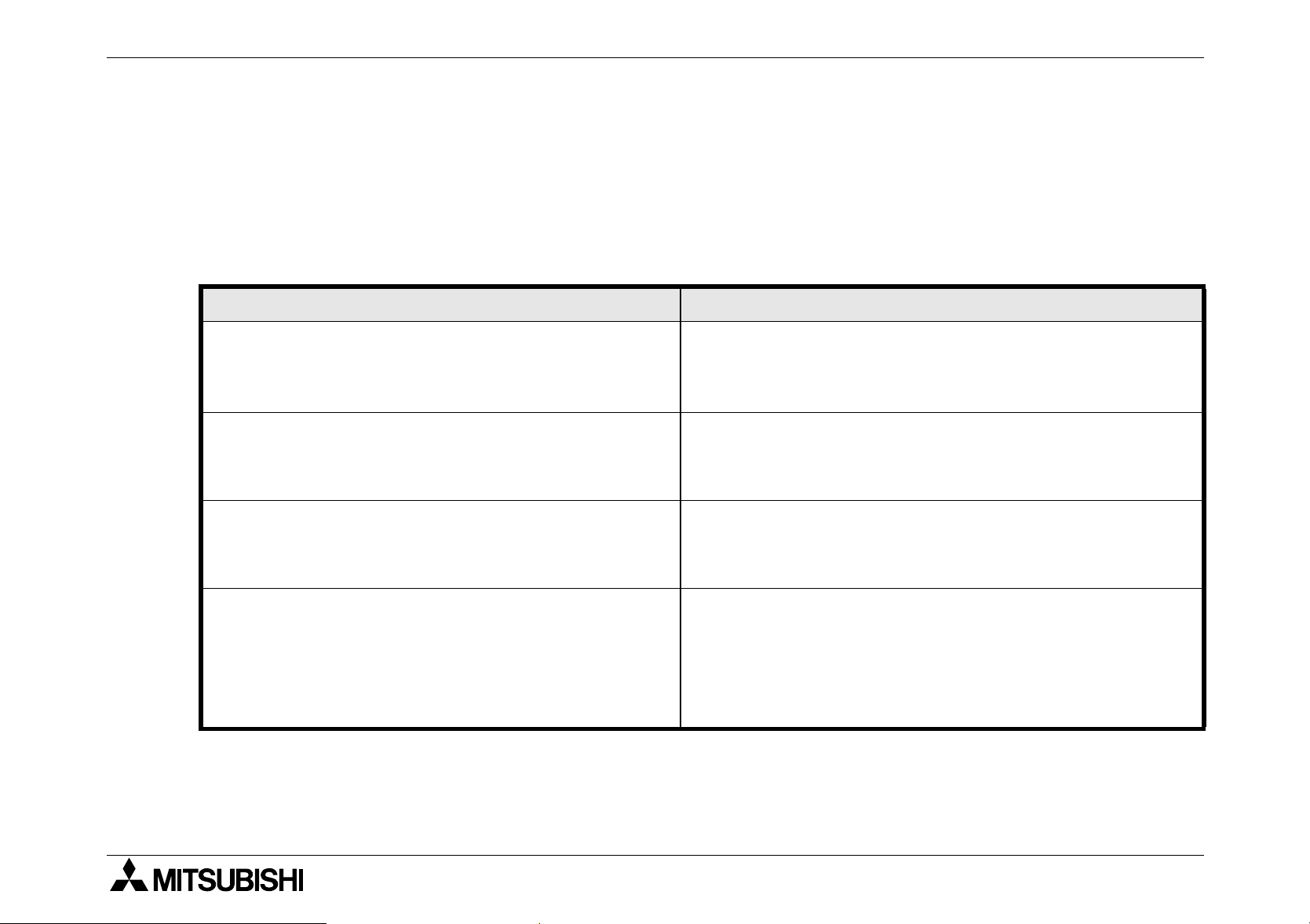
Table 1.1: FX
MODEL
FX1N-14MR-ES/UL
FX1N-14MT-ESS/UL
FX1N-24MR-ES/UL
FX1N-24MT-ESS/UL
FX1N-40MR-ES/UL
FX1N-40MT-ESS/UL
FX1N-60MR-ES/UL
FX1N-60MT-ESS/UL
FX1N-14MR-DS
FX1N-14MT-DSS Transistor
Main Modules
INPUT OUTPUT
QTY TYPE QTY TYPE
8
14
(16)
24 16
36
(40)
8
24V DC
Source
Sink/
6
(8)
10
(16)
24
6
(8)
Relay
Transistor
Relay
Transistor
Relay
Transistor
Relay
Transistor
Relay
POWER
SUPPLY
100-240 VAC
+10%
-15%
50/60Hz
DIMENSIONS
mm (inches)
90
(3.55)
90
(3.55)
130
(5.12)
175
(6.89)
90
(3.55)
90
(3.55)75(2.96)
WEIGHT
kg (lbs)
0.45
(0.99)
0.45
(0.99)
0.65
(1.43)
0.80
(1.76)
0.45
(0.99)
1
2
3
4
5
FX1N-24MR-DS
FX1N-24MT-DSS Transistor
FX1N-40MR-DS
FX1N-40MT-DSS Transistor
FX1N-60MR-DS
FX1N-60MT-DSS Transistor
14
(16)
24 16
36
(40)
24V DC
Sink/
Source
(16)
10
24
Relay
Relay
Relay
12V DC
-15%
to
24V DC
+20%
Note: Occupied points are shown in brackets for input and outputs.
90
(3.55)
130
(5.12)
175
(6.89)
90
(3.55)75(2.96)
1-1
0.45
(0.99)
0.65
(1.43)
0.80
(1.76)
6
7

FX1N Series Programmable Controllers Introduction 1.
Figure 1.1 :Main unit outline
2 - φ4.5 (0.17'')
82 (3.23'')
90 (3.55'')
24V
L
0V
COM0 COM1
X1
S/S
N
Y0
Y1
X0 X2
COM2
X3 X5
Y2
Y3
COM3
X7
COM4
X11
X6
X10
0123
4567
14 15
FX1N-24MR
0123
4567
Y10Y5
Y6
Y7
X4
Y4
POWER
RUN
ERROR
1110
X15
X1
X12
X14
131110 12
IN
OUT
Y11
W - 8 (0.32'')
W
75 (2.96'')
Please see the previous page for each units width measurement.
UNITS: mm (inches)
27.3(1.08")
DIN rail
mounting
slot
27.3(1.08")
8 (0.32'')
1-2
FX1N Series Programmable Controllers Introduction 1.
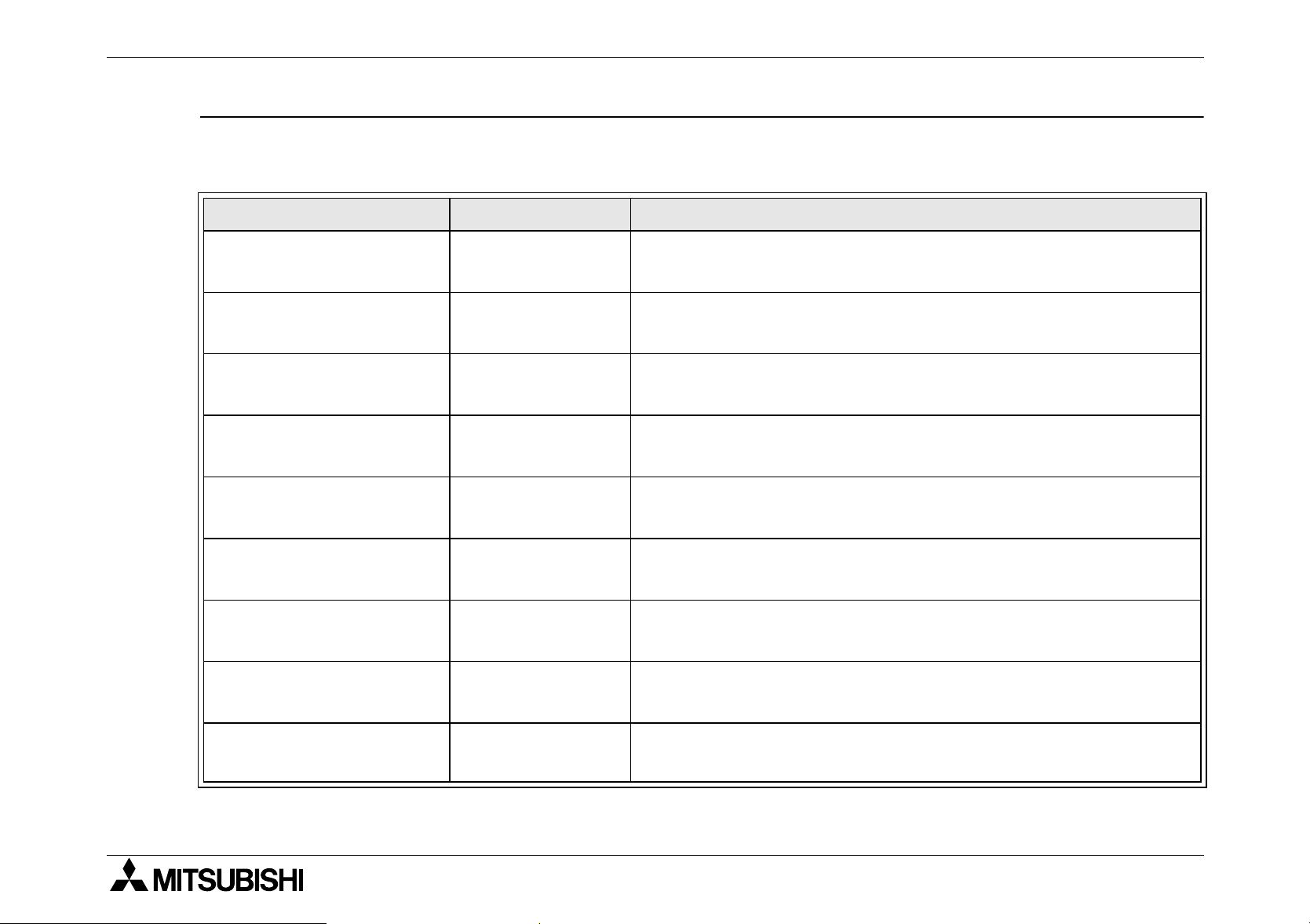
Table 1.2: Powered Extension Units
MODEL
FX0N-40ER-ES/UL
FX0N-40ET-DSS
FX0N-40ER-DS
FX2N-32ER-ES/UL
FX2N-32ET-ESS/UL
FX2N-48ER-ES/UL
FX2N-48ET-ESS/UL
FX2N-48ER-UA1/UL
INPUT OUTPUT
QTY TYPE QTY DEVICE
24
24 16
24V DC
24 16 Relay
16 16 Relay
16 16
24 24 Relay
24 24
24 110VAC 24 Relay
Sink/
Source
16 Relay
Transistor
(Source)
Transistor
(Source)
Transistor
(Source)
POWER
SUPPLY
100-
240VAC
+10%,
-15%
50/60Hz
24VDC
+20%
-15%
100-
240VAC
+10%,
-15%
50/60Hz
100-
240VAC
+10%,
-15%
50/60Hz
DIMENSIONS
mm (inches)
150
(5.91)
90
150
(5.91)
182
(7.17)
220
(8.67)
(3.55)87(3.43)
WEIGHT
kg (lbs)
0.75
(1.65)
0.65
(1.43)
0.85
(1.87)
1.00
(2.2)
1
2
3
4
5
6
1-3
7

FX1N Series Programmable Controllers Introduction 1.
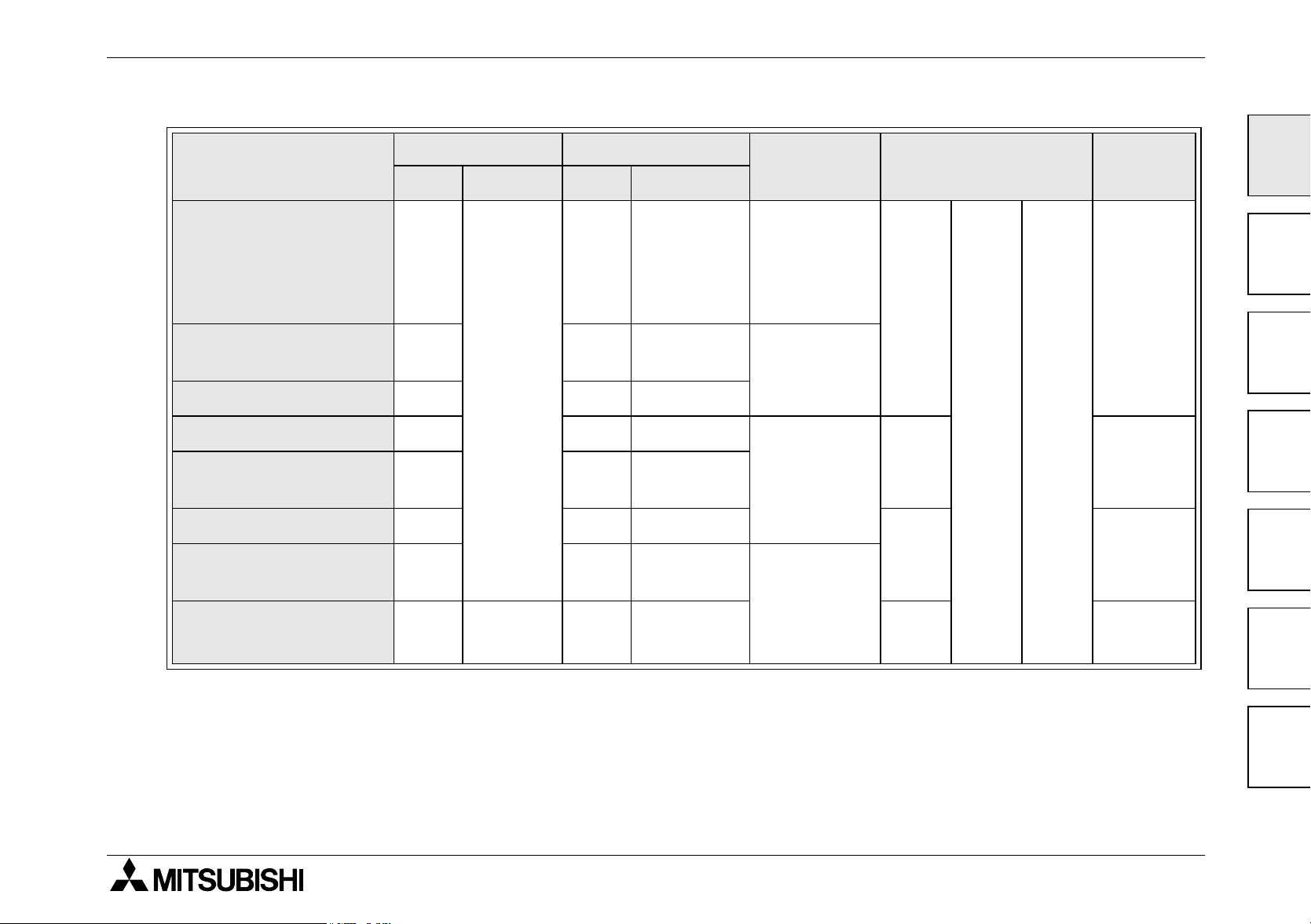
Table 1.3: Extension blocks
MASS
(WEIGHT)
kg (lbs)
MODEL
INPUT OUTPUT
QTY TYPE QTY DEVICE TYPE
DIMENSIONS
mm (inches)
FX0N-8EX-UA1/UL
110V
FX
2N
-8EX-UA1/UL
8
AC
-- -
inputs
FX0N-8EX-ES/UL
FX
2N
-8EX-ES/UL
8
24V DC
-- -
Sink/
FX0N-8ER-ES/UL
2N
FX
-8ER-ES/UL
44
Source
-
Relay
FX0N-8EYR-ES/UL
--8 -
2N
FX
-8EYR-ES/UL
FX0N-8EYT-ESS/UL
- - 8 Transistor Source
2N
FX
-8EYT-ESS/UL
24V DC
FX0N-16EX-ES/UL 16
Sink/
-- -
Source
FX0N-16EYR-ES/UL - - 16 Relay FX0N-16EYT-ESS/UL - - 16 Transistor Source
43
(1.70)
70
(2.76)
0.2
(0.44)
90
(3.55)87(3.43)
0.3
(0.66)
24V DC
FX2N-16EX-ES/UL 16
Sink/
-- -
Source
FX2N-16EYR-ES/UL - - 16 Relay FX2N-16EYT-ESS/UL - - 16 Transistor Source
40
(1.58)90(3.55)87(3.43)
0.3
(0.66)
1-4
 Loading...