


FX1N JAPANESE SPECIFICATION UNITS
HARDWARE MANU AL
JY997D07901A
This manual conta ins safety infor mation, assoc iated manua l listing s, specific ations and ter minal layouts
and wiring for Japanese specification FX
1N
PLC main units.
For complete operation , mounting and programming ins truction s please refer to th e FX1N HANDY
MANUAL (JY992D87501 JAPANESE ONLY) and PROGRAMMING MANUAL.
These manuals should be read and understood before attempting to install or use the unit.
Guidelines for the Safety of the User and Protection of the FX1N PLC
This manual has been wr itten to be used by trained and competent personnel. The definition of such a
person or persons is as follows:
a) Any engineer who i s responsible fo r the planni ng, design and construction of automatic equipm ent using the
product associated with this manual, should be of a competent nature, tr ained and qualified to the local and
national standards. These engineers should be fully aware of all aspects of safety with regards to automated
equipment.
b) Any commissioning or service engi neer must be of a compete nt nature, trained an d qualified to the local and
national standards. These engineers should also be trained in the use and maintenance of the complete
product. This includes being completely familiar with all associa ted documentation for the said product. All
maintenance should be carried out in accordance with established safety practices
c) All operators of th e completed equipment should be trai ned to use that product in a safe and co-ordin ated
manner in compliance to established safety practices. The operators should also be familiar with documentation
which is connected to the actual operation of the completed equipment
Note:
The term ‘completed equipment’ refers to a third par ty constructed device which contains or us es
the product associated with this manual.
Note’s on the Symbols Used in this Manual
At various times through out this manual certain symbols will be used to highlight points of information
which are intended to ensure the users personal safety and protect the integrity of equipment.
1) Indicates that the identified danger could
POSSIBLY
cause physical and property damage.
2) Indicates a point of further interest or further explanation.
• Under no circumstances will Mitsubishi Electric be liable or responsible for any consequential damage
that may arise as a result of the installation or use of this equipment.
• All examples and diagrams shown in this manual are intended only as an aid to understanding the
text, not to guarantee operation. Mitsubish i Electr ic will accep t no respo nsibility for actual us e of the
productbased on these illustrative exam ples.
• Owing to the very great variety in possible application of this equipment, you must satisfy yourself as
to its suitability for your specific applic ation.
Further Information Manual Lists
The following manuals are recomm ende d as essen tial reference m ater ial for the corr ect operat ion of an
FX
1N
series Programmable Controller
Manual name Manual No. Description
FX1N
HANDY MA NUAL
JY992D87501
(JAPANESE ONLY)
Describes contents related to hardware of world
specification FX
1N
series PLCs such as
specifications, wiring and installation.
FX1S, FX1N, FX2N, FX
2NC
PROGRAMMING
MANUAL
JY992D62001
(JAPANESE ONLY)
Programming manual for FX
1S
, FX1N, FX2N and
FX
2NC
series Programmable Logic Controllers
1. Introduction
This manual covers basic hardware details for th e FX1N Series Programmable Logic Controller.
1.1 World Specification
MODEL
INPUT OUTPUT
POWER
SUPPLY
QTY TYPE QTY TYPE
FX1N-24MR
14
(16)
24V DC
SINK
10
(16)
Relay
100-240
VAC
+10%
-15%
50/60Hz
FX
1N
-24MT
Transistor
FX
1N
-40MR
24 16
Relay
FX
1N
-40MT
Transistor
FX1N-60MR
36
(40)
24
Relay
FX
1N
-60MT
Transistor
FX1N-24MR-D
14
(16)
24V DC
SINK
10
(16)
Relay
12V DC
-15%
to
24V DC
+20%
FX
1N
-24MT-D
Transistor
FX1N-40MR-D
24 16
Relay
FX1N-40MT-D
Transistor
FX
1N
-60MR-D
36
(40)
24
Relay
FX
1N
-60MT-D
Transistor
Input - Sink/Source
World Spec models: SINK/SOURCE. Japanese models: ALWAYS SINK
Output - Transisto r
World Spec models: ALWAYS SOURCE . Japanese models: ALWAYS SINK
2. Specifications
The installation of FX1N products has been designed to be safe and easy. When t he products assoc iated
with this manual are used as a system or individually, they must be installed in a suitable enclosure. The
enclosure should be selected and installed in accordance to the local and national standards.
Item Description
Operating Temperature 0 to 55 °C (32 to 131 °F)
Storage Temperature -20 to 70 °C (-4 to 158 °F)
Operating Humidity 35 to 85% Relative Humidity, No condensation
storage Humidity 35 to 90% Relative Humidity, No condensation
Vibration Resistance
- Direct Mounting
Conforms to IEC 68-2-6; 10 - 57 Hz: 0.75 mm Half Amplitude
57 - 150 Hz: 9.8 m/s
Sweep Count for X, Y, Z: 10 times (80 min in each direction)
Vibration Resistance
- DIN rail Mounting
Conforms to IEC 68-2-6; 10 - 57 Hz: 0.035 mm Half Amplitude
57 -150 Hz: 4.9 m/s
Sweep Count for X, Y, Z: 10 times (80 min in each direction)
Shock Resistance
Conforms to IEC 68-2-27: 147m/s2 Acceleration, Action Time: 11ms
3 times in eac h direction X, Y, and Z
Noise Immunity 1000 Vp-p, 1microsecond, 30 - 100 Hz, tested by noise s imulator
Dielectric Withstand
Voltage
AC unit = 1500 V AC > 1 min, tested between all points, terminals and ground
DC unit = 500 V AC > 1 min, tested between all points, terminals and ground.
Insulation Resistance 5 MΩ > at 500 V DC, tested between all points, terminals and ground
Grounding
Grounding resistance 100 Ω or less
Use a cable of at least 0.2mm
2
(AWG24) to ground equipment.
Note that ground cable must not be connected to the s ame ground as power
circuits. Grounding is recommended but if a proper ground cann ot be
provided, the PLC will operate correctly without.
Item Description
Industrial automation
Elincom
Group
EuropeanUnion: www.elinco.eu
Russia: www.elinc.ru

1N
PLC
1N
HANDY
1. Introduction
This manual covers basic hardware details for th e FX1N Series Programmable Logic Controller.
INPUT OUTPUT
QTY TYPE QTY TYPE
14
(16)
24 16
36
(40)
14
(16)
24 16
36
(40)
FX
FX
FX
FX
FX
FX
FX
FX
FX
FX
FX
FX
MODEL
1N
-24MR
1N
-24MT
1N
-40MR
1N
-40MT
1N
-60MR
1N
-60MT
1N
-24MR-D
1N
-24MT-D
1N
-40MR-D
1N
-40MT-D
1N
-60MR-D
1N
-60MT-D
1.1 World Specification
Input - Sink/Source
Output - Transisto r
World Spec models: SINK/SOURCE. Japanese models: ALWAYS SINK
World Spec models: ALWAYS SOURCE . Japanese models: ALWAYS SINK
24V DC
SINK
24V DC
SINK
10
(16)
24
10
(16)
24
Relay
Transistor
Relay
Transistor
Relay
Transistor
Relay
Transistor
Relay
Transistor
Relay
Transistor
POWER
SUPPLY
100-240
VAC
+10%
-15%
50/60Hz
12V DC
-15%
to
24V DC
+20%
DIMENSIONS
mm (inches)
90
(3.6)
90
130
(3.5)
(5.2)
175
(7.0)
90
(3.6)
90
130
(3.5)
(5.2)
175
(7.0)
75
(3.0)
75
(3.0)
WEIGHT
kg (lbs)
0.45
(0.99)
0.65
(1.44)
0.80
(1.77)
0.45
(0.99)
0.65
(1.44)
0.80
(1.77)
2.1 Power Specifications
AC Powered Units FX
Power Supply 100-240V AC +10% -15%, 50-60 Hz
Max. allowable momentary power failure 10ms; If less than 10ms, PLC continues operation
Fuse (size) rating 250V 1A 250V 3.15A (3A)
In-rush current
Power Consumption *1 30W 32W 35W
*1 Includes the input current (7 or 5 mA per point)
DC Powered Units FX
Power S upply 24V DC + 20% - 12V DC -15% (28.8 ~ 10.2 V DC)
Max. allowable momentary power failure 5ms; If less than 5ms, PLC continues operation
Fuse (size) rating 125V 3.15A (3A)
In-rush current
Power Consumption
2.2 Input Specifications
Input voltage 24V DC
Input current 24V DC, 7mA 24V DC, 5mA 24V DC, 5mA
!
Input switching current
Response time 10ms
Variable response time 0-15ms ---
Circuit isolation Photocoupler
Operation indication LED is lit
OFF
ON ! OFF <1.5mA
2. Specifications
The installation of FX1N products has been designed to be safe and easy. When t he products assoc iated
with this manual are used as a system or individually, they must be installed in a suitable enclosure. The
enclosure should be selected and installed in accordance to the local and national standards.
Item Description
Operating Temperature 0 to 55 °C (32 to 131 °F)
Storage Temperature -20 to 70 °C (-4 to 158 °F)
Operating Humidity 35 to 85% Relative Humidity, No condensation
storage Humidity 35 to 90% Relative Humidity, No condensation
Vibration Resistance
- Direct Mounting
Item Description
Vibration Resistance
- DIN rail Mounting
Shock Resistance
1S
, FX1N, FX2N and
Noise Immunity 1000 Vp-p, 1microsecond, 30 - 100 Hz, tested by noise s imulator
Dielectric Withstand
Voltage
Insulation Resistance 5 MΩ > at 500 V DC, tested between all points, terminals and ground
Grounding
Conforms to IEC 68-2-6; 10 - 57 Hz: 0.75 mm Half Amplitude
57 - 150 Hz: 9.8 m/s
2
Acceleration
Sweep Count for X, Y, Z: 10 times (80 min in each direction)
Conforms to IEC 68-2-6; 10 - 57 Hz: 0.035 mm Half Amplitude
57 -150 Hz: 4.9 m/s
2
Acceleration
Sweep Count for X, Y, Z: 10 times (80 min in each direction)
Conforms to IEC 68-2-27: 147m/s
2
Acceleration, Action Time: 11ms
3 times in eac h direction X, Y, and Z
AC unit = 1500 V AC > 1 min, tested between all points, terminals and ground
DC unit = 500 V AC > 1 min, tested between all points, terminals and ground.
Grounding resistance 100 Ω or less
Use a cable of at least 0.2mm
2
(AWG24) to ground equipment.
Note that ground cable must not be connected to the s ame ground as power
circuits. Grounding is recommended but if a proper ground cann ot be
provided, the PLC will operate correctly without.
2.3 Output Specifica tions
Description Relay Output Transistor Output
Switched voltages (resistive load)
Rated current / N points
(resistive load)
Max. Inductive load 80VA, 120/240V AC 12W/24V DC
Max. lamp l oad (tungsten load)
Minimum load
OFF
ON
ON
!
OFF
!
Response
time (approx.)
Circuit isolation By Relay PhotoCoupler
Open circuit current leakage ---------------- 0.1mA/30V DC
Operation indication LED is lit when coil is energized
100W (1.17A/85V AC, 0.4A/
3. Installation Notes
The installation of FX1N products has been designed to be safe and easy. If during the installation of these
products or associated products concern is felt, please contact a professional electrician who is trained to
the local and national standards applicable to the installation site.
1N
FX
Main PLC units can be either directly or DIN rail mou nted. For details of either met hod, and
installation guidelines please refer to the FX
Mounting Cautions
• Units should not be installed in areas subject to the following conditions: excessive or con-
ductive dust, corrosive or flammable gas, moisture or rain, exc essive heat, regular impact
shocks or excessive vibrat ion.
• Take special care not to allow debris to fall inside the unit during installation e.g. cut wires,
shavings etc. Once installation is complete remove the protective paper band, to prevent
overheating.

DIMENSIONS
mm (inches)
WEIGHT
kg (lbs)
90
(3.6)
90
(3.5)
75
(3.0)
0.45
(0.99)
130
(5.2)
0.65
(1.44)
175
(7.0)
0.80
(1.77)
90
(3.6)
90
(3.5)
75
(3.0)
0.45
(0.99)
130
(5.2)
0.65
(1.44)
175
(7.0)
0.80
(1.77)
Acceleration
Acceleration
2.1 Power Specifications
*1 Includes the input current (7 or 5 mA per point)
2.2 Input Specifications
AC Powered Units FX1N-24M FX1N-40M FX1N-60M
Power Supply 100-240V AC +10% -15%, 50-60 Hz
Max. allowable momentary power failure 10ms; If less than 10ms, PLC continues operation
Fuse (size) rating 250V 1A 250V 3.15A (3A)
In-rush current
100V AC - Max. 30A for 5ms
200V AC - Max. 50A for 5ms
Power Consumption *1 30W 32W 35W
DC Powered Units FX1N-24M FX1N-40M FX1N-60M
Power S upply 24V DC + 20% - 12V DC -15% (28.8 ~ 10.2 V DC)
Max. allowable momentary power failure 5ms; If less than 5ms, PLC continues operation
Fuse (size) rating 125V 3.15A (3A)
In-rush current
24V DC - Max. 25A for 1ms
12V DC - Max. 22A for 0.3ms
Power Consumption
15W 18W 20W
FX1N Main unit
FX0N, FX2N Extension
block
X0
!!!!
X7 X10
!!!!
∞
Input voltage 24V DC ±10%
Input current 24V DC, 7mA 24V DC, 5mA 24V DC, 5mA
Input switching current
OFF ! ON >4.5mA >3.5mA >3.5mA
ON ! OFF <1.5mA
Response time 10ms
Variable response time 0-15ms --Circuit isolation Photocoupler
Operation indication LED is lit
2.3 Output Specifica tions
Description Relay Output Transistor Output
Switched voltages (resistive load)
≤
240V AC, ≤ 30V DC 5-30V DC
Rated current / N points
(resistive load)
2A/1 point, 8A/COM 0.5A/1 point, 0.8A/COM
Max. Inductive load 80VA, 120/240V AC 12W/24V DC
Max. lamp l oad (tungsten load)
100W (1.17A/85V AC, 0.4A/
250V AC)
1.5W/24V DC
Minimum load
When supply voltage < 5V
DC allow at least 2mA flow
------------------
Response
time (approx.)
OFF
!
ON
10ms < 0.2ms; < 5µs (Y0,Y1 only)
ON
!
OFF
10ms < 0.2ms (I > 0.2A); <5µs (Y0,Y1 only)
Circuit isolation By Relay PhotoCoupler
Open circuit current leakage ---------------- 0.1mA/30V DC
Operation indication LED is lit when coil is energized
3. Installation Notes
The installation of FX1N products has been designed to be safe and easy. If during the installation of these
products or associated products concern is felt, please contact a professional electrician who is trained to
the local and national standards applicable to the installation site.
FX
1N
Main PLC units can be either directly or DIN rail mou nted. For details of either met hod, and
installation guidelines please refer to the FX
1N
HANDY MANUAL JY992D87501 (JAPANESE ONLY).
Mounting Cautions
• Units should not be installed in areas subject to the following conditions: excessive or conductive dust, corrosive or flammable gas, moisture or rain, exc essive heat, regular impact
shocks or excessive vibrat ion.
• Take special care not to allow debris to fall inside the unit during installation e.g. cut wires,
shavings etc. Once installation is complete remove the protective paper band, to prevent
overheating.

4. T erminal Layouts
The following selection of terminal layouts are taken from the FX1N product range.
Note: All layouts are diagramm at ic and are only intended to aid the creation of wiring diagrams.
4.1 AC Powered Main Units
COM
X1
X0 X4
X5
COM
Y0 Y1 Y2 Y3
X3
X2
24+
X7
X6
Y5
X12
X13X11
X10
X15
X14
Y6 Y10
Y7 Y11
COM0 COM1 COM2 COM3Y4COM4
FX1N-24MR / 24MT
N
L
COM
X1
N X0 X4
FX1N-60MR / 60MT
X5
COM
Y0 Y1 Y2
Y3
X3
X2
24+
COM0 COM1 COM3COM2
L
X7
X6
Y5
COM4
X12
X13X11
X10
X15
X14
Y6Y4 Y14
Y7 Y11
X20
X21X17
X16
X23
X22 X24
X25
X26
X27
Y10 Y12
Y13
COM5
Y16
Y15 Y17
X31
X30 X32
X33
X34
X35
X40
X41
X42
X43
Y20 Y22
Y21 Y23
COM6
Y24 Y26
Y25 Y27
COM7
X36
X37
COM
X1
N X0 X4
FX1N-40MR / 40MT
X5
COM
Y0 Y1 Y2
Y3
X3
X2
24+
COM0 COM1 COM3COM2
L
X7
X6
Y5
COM4
X12
X13X11
X10
X15
X14
Y6Y4 Y14
Y7 Y11
X20
X21X17
X16
X23
X22 X24
X25
X26
X27
Y10 Y12
Y13
COM5
Y16
Y15 Y17
4.2 DC Powered Main Units
COM
X1
X0 X4
FX1N-24MR-D / 24MT-D
X5
COM Y0 Y1 Y2 Y3
X3
X2
24+
COM0 COM1 COM3COM2
X7
X6
Y5
COM4
X12
X13X11
X10
X15
X14
Y6Y4Y10
Y7 Y11
-
+
COM
X1
X0 X4
FX1N-40MR-D / MT-D
X5
COM
Y0 Y1 Y2
Y3
X3
X2
24+
COM0 COM1 COM3COM2
X7
X6
Y5
COM4
X12
X13X11
X10
X15
X14
Y6Y4 Y14
Y7 Y11
X20
X21X17
X16
X23
X22 X24
X25
X26
X27
Y10 Y12
Y13
COM5
Y16
Y15 Y17
-
+
COM
X1
X0 X4
FX1N-60MR-D / MT-D
X5
COM
Y0 Y1 Y2
Y3
X3
X2
24+
COM0 COM1 COM3COM2
X7
X6
Y5
COM4
X12
X13X11
X10
X15
X14
Y6Y4 Y14
Y7 Y11
X20
X21X17
X16
X23
X22 X24
X25
X26
X27
Y10 Y12
Y13
COM5
Y16
Y15 Y17
X31
X30 X32
X33
X34
X35
X40
X41
X42
X43
Y20 Y22
Y21 Y23
COM6
Y24 Y26
Y25 Y27
COM7
X36
X37
-
+
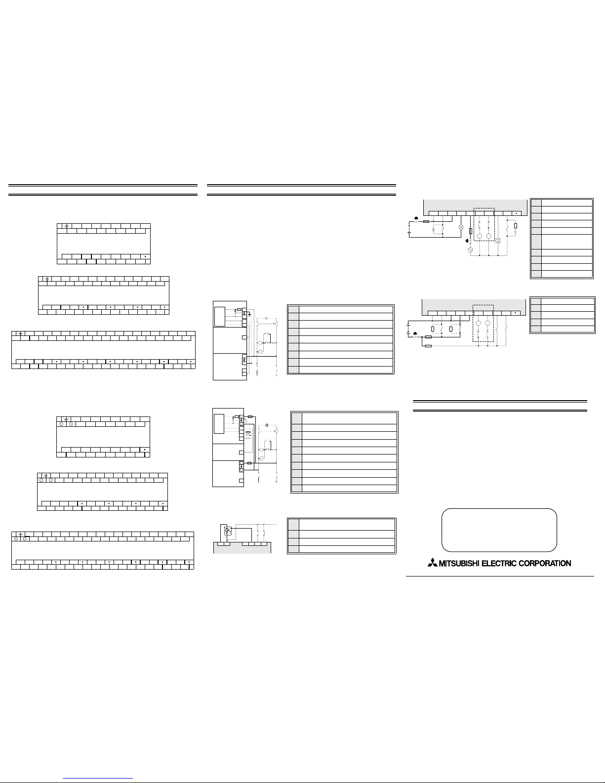
5. Example Wiring
If during the wiring of these products or associated products concern is felt, please contact a professional
electrician who is trained in the local and national standards applicable to the installation site.
Wiring cautions
• Do not run input signals in the same multicore cable as output signals or allow them to
share the same wire.
• Do not lay I/O signal cables ne xt to po wer cables or allow t hem to share the same trunking
duct. Low voltage cables should be reliably separated or insulated with regard to high
voltage cabling.
• Where I/O signal lines are used over an extended distance consideration for voltage drop
and noise interference should be made.
• Always ensure that mounted units and blocks are kept as far as possible from
high-voltage cables, high-volt age equipment and power equipment.
Both Japanese an d World Spec ifica tion Exte nsion blocks/u nits and s pecial functio n blocks can be used
with these main units.
5.1 AC Power Supply
"
Power supply 100-240V AC +10% -15% 50-60Hz
#
Emergency stop
$
Power supply switch
%
Pow er ON pilot indicator
&
Power supply for loads
'
Ground
(
Fuse
)
Main unit
*
Breaker
AC/DC
Converter
Extension block
Extension unit
MC
PL
MC
MC MC
24+
24+
COM
24+
COM
L
N
L
N
#
$
%
"
&
&
'
(
)
*
5.2 DC Power Supply
"
Power supply 12-24V DC +20% -15%
20.4-28.8V DC when using extension unit.
#
Circuit protector or fuse
$
Emergency stop
%
Power supply switch
&
Power ON pilot indicator
'
Power supply for loads
(
Ground
)
Fuse
*
Main unit
+
Breaker
DC/DC
Converter
Extension block
Extension unit
MC
PL
MC
MC MC
24+
24+
COM
COM
-
+
L
N
X000
X001
"
#
#
$
%
&
''
(
)
*
+
#
+
-
+
-
5.3 Input
Note
• W hen using a DC powered unit, the input circuit power supply should be used. If an
external 24V DC supply is used, the FX
1N
will not operate correctly.
• Japanese specification models are ALWAYS SINK input
"
AC Model - Service supply
DC Model - Input circuit power supply
#
NPN Sensor
$
Input Device Contact
%
Main unit
24+ COM
COM
X0 X1 X2
NPN
"
#
$
%
COM0
Y0 Y1 Y2 Y3
COM1 COM2
Y4 Y5
MC1 MC2
MC2 MC1
+
'
COM0
Y0 Y1 Y2 Y3
COM1 COM2
Y4 Y5
MC1 MC2
MC2 MC1
+

X15
COM0
Y0 Y1 Y2 Y3
COM1 COM2
Y4 Y5
MC1 MC2
MC2 MC1
+
'
COM0
Y0 Y1 Y2 Y3
COM1 COM2
Y4 Y5
MC1 MC2
MC2 MC1
+
X14
X23
X22 X24
COM5
X31
X30 X32
Y20 Y22
COM6
Y21 Y23
X25
X26
Y16
Y15 Y17
X33
X34
X27
X35
X37
X36
Y24 Y26
COM7
X41
X40
X42
Y25 Y27
X43
5. Example Wiring
If during the wiring of these products or associated products concern is felt, please contact a professional
electrician who is trained in the local and national standards applicable to the installation site.
Wiring cautions
• Do not run input signals in the same multicore cable as output signals or allow them to
share the same wire.
• Do not lay I/O signal cables ne xt to po wer cables or allow t hem to share the same trunking
duct. Low voltage cables should be reliably separated or insulated with regard to high
voltage cabling.
• Where I/O signal lines are used over an extended distance consideration for voltage drop
and noise interference should be made.
• Always ensure that mounted units and blocks are kept as far as possible from
high-voltage cables, high-volt age equipment and power equipment.
Both Japanese an d World Spec ifica tion Exte nsion blocks/u nits and s pecial functio n blocks can be used
with these main units.
5.1 AC Power Supply
)
AC/DC
Converter
Extension block
Extension unit
(
L
'
N
24+
COM
24+
L
N
24+
COM
"
*
MC
MC
$
#
PL
%
MC MC
&
&
Power supply 100-240V AC +10% -15% 50-60Hz
"
Emergency stop
#
Power supply switch
$
Pow er ON pilot indicator
%
Power supply for loads
&
Ground
'
Fuse
(
Main unit
)
Breaker
*
5.4 Output
&
#
*
&
#
$
$
$
(
&
+
X15
X14
X23
X22 X24
COM5
Y15 Y17
X31
X30 X32
Y20 Y22
COM6
Y21 Y23
X25
Y16
X33
X27
X26
X34
X35
X41
X37
X36
Y24 Y26
COM7
X43
X40
X42
Y25 Y27
5.2 DC Power Supply
*
)
#
+
+
24+
COM
X000
X001
24+
N
COM
(
-
-
#
+
L
-
DC/DC
Converter
Extension block
Extension unit
5.3 Input
#
NPN
24+ COM
COM
"
• W hen using a DC powered unit, the input circuit power supply should be used. If an
external 24V DC supply is used, the FX
• Japanese specification models are ALWAYS SINK input
Note
"
#
+
MC
MC
%
PL
&
MC MC
''
$
X0 X1 X2
%
Additional information
Power supply 12-24V DC +20% -15%
"
20.4-28.8V DC when using extension unit.
Circuit protector or fuse
#
Emergency stop
$
Power supply switch
%
Power ON pilot indicator
$
&
Power supply for loads
'
Ground
(
Fuse
)
Main unit
*
Breaker
+
AC Model - Service supply
"
DC Model - Input circuit power supply
NPN Sensor
#
Input Device Contact
$
Main unit
%
1N
will not operate correctly.
Additional information regarding:
• Product Outline
• World Specification Extension Units / Blocks and Special Function Blocks
• Configuration Schematics
• Current Consumption and Rules of Expansion
• Back up Data procedure and details
• Diagnostic information, Instruction and Device lists
Can be found in the FX
1N
HANDY MANUAL (JY992D87501 JAPA NESE ONLY). It is strongly
recommended that this manual is read and understood before the use or configuration of this
product.
Manual number: JY997D07901
Manual revision: A
Date : November 2002
HEAD OFFICE : MITSUBISHI DENKI BLDG MARUNOUTI TOKYO 100-8310 TELEX : J24532 CABLE MELCO TOKYO
HIMEJI WORKS : 840, CHIYODA CHO, HIMEJI, JAPAN
JY997D07901A

HEAD OFFICE : MITSUBISHI DENKI BLDG MARUNOUTI TOKYO 100-8310 TELEX : J24532 CABLE MELCO TOKYO
HIMEJI WORKS : 840, CHIYODA CHO, HIMEJI, JAPAN
5.4 Output
Typical Relay
"
Do not use this terminal
#
Fuse
$
Surge absorbing Diode
%
External Mechanical Interlock
&
Emergency Stop
'
Noise Suppressor 0.1µF
capacitor + 100-200Ω resistor
Contactor
(
Valve
)
Incandescent Lamp
*
DC Power Supply
+
AC Power Supp ly
COM0
Y0 Y1 Y2 Y3
COM1 COM2
Y4 Y5
MC1 MC2
MC2 MC1
+
"
#
$
%
&
&
'
(
)
*
+
Japanese model Transistor
"
Do not use this terminal
#
Emergency Stop
$
Fuse
%
External Mechani cal Inte r l ock
&
DC Power Supply
COM0
Y0 Y1 Y2 Y3
COM1 COM2
Y4 Y5
MC1 MC2
MC2 MC1
+
"
#
$
$
%
&
Additional information
Additional information regarding:
• Product Outline
• World Specification Extension Units / Blocks and Special Function Blocks
• Configuration Schematics
• Current Consumption and Rules of Expansion
• Back up Data procedure and details
• Diagnostic information, Instruction and Device lists
Can be found in the FX
1N
HANDY MANUAL (JY992D87501 JAPA NESE ONLY). It is strongly
recommended that this manual is read and understood before the use or configuration of this
product.
Manual number: JY997D07901
Manual revision: A
Date : November 2002
JY997D07901A
Effective November 2002
Specifications are subject to
change without notice

FX1N JAPANESE SPECIFICATION UNITS
HARDWARE MANUAL
JY997D07901A
This manual contains safety information , assoc iated m anual listing s, specif ications and ter minal layouts
and wiring for Japanese specification FX
1N
PLC main units.
For complete operation, mounting and programming ins truction s please refer to the F X
1N
HANDY
MANUAL (JY992D87501 JAPAN ESE ONLY) and PROGRAMMING MA NUAL.
These manuals should be read and understood before attempting to install or use the unit.
Guidelines for the Safety of the User and Protection of the FX1N PLC
This manual has been written to be used by trained and competent personnel. The definition of such a
person or persons is as follows:
a) Any engineer who is responsible for the planning, design a nd construction of automatic eq uipment using the
product associated with this manual, should be of a competent nature, trained and qualified to the local and
national standards. These engineers should be fully aware of all aspects of safety with regards to automated
equipment.
b) Any commissioning or service engineer must be of a competent nat ure, train ed and quali fied to the local and
national standards. These engineers should also be trained in the use and maintenance of the complete
product. This includes being completely familiar with all associated documentation for the said product. All
maintenance should be carried out in accordance with established safety practices
c) All operators of the completed equipment should be trained to use that produc t in a safe and co-ordinated
manner in compliance to established safety practices. The operators should also be familiar with documentation
which is connected to the actual operation of the completed equipment
Note:
The term ‘completed equipment’ refers to a third party constructed device which contains or uses
the product associated with this manual.
Note’s on the Symbols Used in this Manual
At various times through out this manual certain symbols will be used to highlight points of information
which are intended to ensure the users personal safety and protect the integrity of equipment.
1) Indicates that the identified danger could
POSSIBLY
cause physical and property damage.
2) Indicates a point of further interest or further explanation.
• Under no circumstances will Mitsubishi Electric be liable or responsible for any consequential damage
that may arise as a result of the installation or use of this equipment.
• All examples and diagrams shown in this manual are intended only as an aid to understanding the
text, not to guarantee operation. Mitsubishi Electric will acc ept no respo nsibili ty for actual use of the
productbased on these illustrative examples.
• Owing to the very great variety in possible application of this equipment, you must satisfy yourself as
to its suitability for your specific application.
Further Information Manual Lists
The following manuals are recommended as esse ntial re ference mater ial for the co rrect ope ration of an
FX
1N
series Programmable Controller
Manual name Manual No. Description
FX
1N
HANDY MANUAL
JY992D87501
(JAPANESE ONLY)
Describes contents related to hardware of world
specification FX
1N
series PLCs such as
specifications, wiring and installation.
FX
1S
, FX1N, FX2N, FX
2NC
PROGRAMMING
MANUAL
JY992D62001
(JAPANESE ONLY)
Programming manual for FX
1S
, FX1N, FX2N and
FX
2NC
series Programmable Logic Controllers
1. Introduction
This manual covers basic hardware details for the FX1N Series Programmable Logic Controller.
1.1 World Specification
MODEL
INPUT OUTPUT
POWER
SUPPLY
DIMENSIONS
mm (inches)
WEIGHT
kg (lbs)
QTY TYPE QTY TYPE
FX
1N
-24MR
14
(16)
24V DC
SINK
10
(16)
Relay
100-240
VAC
+10%
-15%
50/60Hz
90
(3.6)
90
(3.5)
75
(3.0)
0.45
(0.99)
FX
1N
-24MT
Transistor
FX
1N
-40MR
24 16
Relay
130
(5.2)
0.65
(1.44)
FX
1N
-40MT
Transistor
FX
1N
-60MR
36
(40)
24
Relay
175
(7.0)
0.80
(1.77)
FX
1N
-60MT
Transistor
FX
1N
-24MR-D
14
(16)
24V DC
SINK
10
(16)
Relay
12V DC
-15%
to
24V DC
+20%
90
(3.6)
90
(3.5)
75
(3.0)
0.45
(0.99)
FX
1N
-24MT-D
Transistor
FX
1N
-40MR-D
24 16
Relay
130
(5.2)
0.65
(1.44)
FX
1N
-40MT-D
Transistor
FX
1N
-60MR-D
36
(40)
24
Relay
175
(7.0)
0.80
(1.77)
FX
1N
-60MT-D
Transistor
Input - Sink/Source
World Spec models: SINK/SOURCE. Japanese models: ALWAYS SINK
Output - Transistor
World Spec models: ALWAYS SOURCE. Japanese models: ALWAYS SINK
2. Specifications
The installation of FX1N products has been designed to be safe and easy. When the products associated
with this manual are used as a system or individually, they must be installed in a suita ble enclosure. The
enclosure should be selected and installed in accordance to the local and national standards.
Item Description
Operating Temperature 0 to 55 °C (32 to 131 °F)
Storage Temperature -20 to 70 °C (-4 to 158 °F)
Operating Humidity 35 to 85% Relative Humidity, No condensation
storage Humidity 35 to 90% Relative Humidity, No condensation
Vibration Resistance
- Direct Mounting
Conforms to IEC 68-2-6; 10 - 57 Hz: 0.75 mm Half Amplitude
57 - 150 Hz: 9.8 m/s
2
Acceleration
Sweep Count for X, Y, Z: 10 times (80 min in each direction)
Vibration Resistance
- DIN rail Mounting
Conforms to IEC 68-2-6; 10 - 57 Hz: 0.035 mm Half Amplitude
57 -150 Hz: 4.9 m/s
2
Acceleration
Sweep Count for X, Y, Z: 10 times (80 min in each direction)
Shock Resistance
Conforms to IEC 68-2-27: 147m/s
2
Acceleration, Action Time: 11ms
3 times in each direction X, Y, and Z
Noise Immunity 1000 Vp-p, 1microsecond, 30 - 100 Hz, tested by noise simulator
Dielectric Withstand
Voltage
AC unit = 1500 V AC > 1 min, tested between all points, terminals and ground
DC unit = 500 V AC > 1 min, tested between all points, terminals and ground.
Insulation Resistance 5 MΩ > at 500 V DC, tested between all points, terminals and ground
Grounding
Grounding resistance 100 Ω or less
Use a cable of at least 0.2mm
2
(AWG24) to ground equipment.
Note that ground cable must not be connected to the same ground as power
circuits. Grounding is recommend ed but if a proper ground ca nnot be
provided, the PLC will operate correctly without.
Item Description
2.1 Power Specifications
*1 Includes the input current (7 or 5 mA per point)
2.2 Input Specifications
AC Powered Units FX1N-24M FX1N-40M FX1N-60M
Power Supply 100-240V AC +10% -15%, 50-60 Hz
Max. allowable momentary power failure 10ms; If less than 10ms, PLC continues operation
Fuse (size) rating 250V 1A 250V 3.15A (3A)
In-rush current
100V AC - Max. 30A for 5ms
200V AC - Max. 50A for 5ms
Power Consumption *1 30W 32W 35W
DC Powered Units FX1N-24M FX1N-40M FX1N-60M
Power Supply 24V DC + 20% - 12V DC -15% (28.8 ~ 10.2 V DC)
Max. allowable momentary power failure 5ms; If less than 5ms, PLC continues operation
Fuse (size) rating 125V 3.15A (3A)
In-rush current
24V DC - Max. 25A for 1ms
12V DC - Max. 22A for 0.3ms
Power Consumption
15W 18W 20W
FX1N Main unit
FX0N, FX2N Extension
block
X0
!!!!
X7 X10
!!!!
∞
Input voltage 24V DC ±10%
Input current 24V DC, 7mA 24V DC, 5mA 24V DC, 5mA
Input switching current
OFF ! ON >4.5mA >3.5mA >3.5mA
ON ! OFF <1.5mA
Response time 10ms
Variable response time 0-15ms --Circuit isolation Photocoupler
Operation indication LED is lit
2.3 Output Specifications
Description Relay Output Transistor Output
Switched voltages (resistive load)≤ 240V AC, ≤ 30V DC 5-30V DC
Rated current / N points
(resistive load)
2A/1 point, 8A/COM 0.5A/1 point, 0.8A/COM
Max. Inductive load 80VA, 120/240V AC 12W/24V DC
Max. lamp load (tungsten load)
100W (1.17A/85V AC, 0.4A/
250V AC)
1.5W/24V DC
Minimum load
When supply voltage < 5V
DC allow at least 2mA flow
------------------
Response
time (approx.)
OFF
!
ON
10ms < 0.2ms; < 5µs (Y0,Y1 only)
ON
!
OFF
10ms < 0.2ms (I > 0.2A); <5µs (Y0,Y1 only)
Circuit isolation By Relay PhotoCoupler
Open circuit current leakage ---------------- 0.1mA/30V DC
Operation indication LED is lit when coil is energized
3. Installation Notes
The installation of FX1N products has been designed to be safe and easy. If during the installation of these
products or associated products concern is felt, please contact a professional electrician who is trained to
the local and national standards applicable to the installation site.
FX
1N
Main PLC units can be either directly or DIN rail mou nted. For details of either method , and
installation guidelines please refer to the FX
1N
HANDY MANUAL JY992D87501 (JAPANESE ONLY).
Mounting Cautions
• Units should not be installed in areas subject to the following conditions: excessive or conductive dust, corrosive or flammable gas, moisture or rain, excessive heat, regular impact
shocks or excessive vibration.
• Take special care not to allow debris to fall inside the unit during installation e.g. cut wires,
shavings etc. Once installation is complete remove the protective paper band, to prevent
overheating.
HEAD OFFICE : MITSUBISHI DENKI BLDG MARUNOUTI TOKYO 100-8310 TELEX: J24532 CABLE MELCO TOKYO
HIMEJI WORKS : 840, CHIYODA CHO, HIMEJI, JAPAN
4. Terminal Layout s
The following selection of terminal layouts are taken from the FX1N product range.
Note: All layouts are diagrammatic and are only intended to aid the creation of wiring diagrams.
4.1 AC Powered Main Units
COM
X1
X0 X4
X5
COM
Y0 Y1 Y2 Y3
X3
X2
24+
X7
X6Y5X12
X13X11
X10
X15
X14
Y6 Y10
Y7 Y11
COM0 COM1 COM2 COM3Y4COM4
FX1N-24MR / 24MT
N
L
COM
X1
N X0 X4
FX1N-60MR / 60MT
X5
COM
Y0 Y1 Y2
Y3
X3
X2
24+
COM0 COM1 COM3COM2
L
X7
X6
Y5
COM4
X12
X13X11
X10
X15
X14
Y6Y4 Y14
Y7 Y11
X20
X21X17
X16
X23
X22 X24
X25
X26
X27
Y10 Y12
Y13
COM5
Y16
Y15 Y17
X31
X30 X32
X33
X34
X35
X40
X41
X42
X43
Y20 Y22
Y21 Y23
COM6
Y24 Y26
Y25 Y27
COM7
X36
X37
COM
X1
N X0 X4
FX1N-40MR / 40MT
X5
COM
Y0 Y1 Y2
Y3
X3
X2
24+
COM0 COM1 COM3COM2
L
X7
X6
Y5
COM4
X12
X13X11
X10
X15
X14
Y6Y4 Y14
Y7 Y11
X20
X21X17
X16
X23
X22 X24
X25
X26
X27
Y10 Y12
Y13
COM5
Y16
Y15 Y17
4.2 DC Powered Main Units
COM
X1
X0 X4
FX1N-24MR-D / 24MT-D
X5
COM Y0 Y1 Y2 Y3
X3
X2
24+
COM0 COM1 COM3COM2
X7
X6
Y5
COM4
X12
X13X11
X10
X15
X14
Y6Y4Y10
Y7 Y11
-
+
COM
X1
X0 X4
FX1N-40MR-D / MT-D
X5
COM
Y0 Y1 Y2
Y3
X3
X2
24+
COM0 COM1 COM3COM2
X7
X6
Y5
COM4
X12
X13X11
X10
X15
X14
Y6Y4 Y14
Y7 Y11
X20
X21X17
X16
X23
X22 X24
X25
X26
X27
Y10 Y12
Y13
COM5
Y16
Y15 Y17
-
+
COM
X1
X0 X4
FX1N-60MR-D / MT-D
X5
COM
Y0 Y1 Y2
Y3
X3
X2
24+
COM0 COM1 COM3COM2
X7
X6
Y5
COM4
X12
X13X11
X10
X15
X14
Y6Y4 Y14
Y7 Y11
X20
X21X17
X16
X23
X22 X24
X25
X26
X27
Y10 Y12
Y13
COM5
Y16
Y15 Y17
X31
X30 X32
X33
X34
X35
X40
X41
X42
X43
Y20 Y22
Y21 Y23
COM6
Y24 Y26
Y25 Y27
COM7
X36
X37
-
+
5. Example Wiring
If during the wiring of these products or associated products concern is felt, please contact a professional
electrician who is trained in the local and national standards applicable to the installation site.
Wiring cautions
• Do not run input signals in the same multicore cable as output signals or allow them to
share the same wire.
• Do not lay I /O signal cab les next to power cables or allow them to share the same trunking
duct. Low voltage cables should be reliably separated or insulated with regard to high
voltage cabling.
• Where I/O signal lines are used over an extende d distance cons ideration for voltage drop
and noise interference should be made.
• Always ensure that mounted units and blocks are kept as far as possible from
high-voltage cables, high-voltage equipment and power equipment.
Both Japanese and World Specifica tion Exte nsio n blocks/units an d spec ial funct ion blocks can be used
with these main units.
5.1 AC Power Supply
"
Power supply 100-240V AC +10% -15% 50-60Hz
#
Emergency stop
$
Power supply switch
%
Power ON pilot indicator
&
Power supply for loads
'
Ground
(
Fuse
)
Main unit
*
Breaker
AC/DC
Converter
Extension block
Extension unit
MC
PL
MC
MC MC
24+
24+
COM
24+
COM
L
N
L
N
#
$
%
"
&
&
'
(
)
*
5.2 DC Power Supply
"
Power supply 12-24V DC +20% -15%
20.4-28.8V DC when using extension unit.
#
Circuit protector or fuse
$
Emergency stop
%
Power supply switch
&
Power ON pilot indicator
'
Power supply for loads
(
Ground
)
Fuse
*
Main unit
+
Breaker
DC/DC
Converter
Extension block
Extension unit
MC
PL
MC
MC MC
24+
24+
COM
COM
-
+
L
N
X000
X001
"
#
#
$
%
&
''
(
)
*
+
#
+
-
+
-
5.3 Input
Note
• When using a DC powered unit, the input circuit power supply should be used. If an
external 24V DC supply is used, the FX
1N
will not operate correctly.
• Japanese specification models are ALWAYS SINK input
"
AC Model - Service supply
DC Model - Input circuit power supply
#
NPN Sensor
$
Input Device Contact
%
Main unit
24+ COM
COM
X0 X1 X2
NPN
"
#
$
%
5.4 Output
Typical Relay
"
Do not use this terminal
#
Fuse
$
Surge absorbing Dio de
%
External Mechanical Interlock
&
Emergency Stop
'
Noise Suppressor 0.1µF
capacitor + 100-200Ω resistor
Contactor
(
Valve
)
Incandescent Lamp
*
DC Power Supply
+
AC Power Supply
COM0
Y0 Y1 Y2 Y3
COM1 COM2
Y4 Y5
MC1 MC2
MC2 MC1
+
"
#
$
%
&
&
'
(
)
*
+
Japanese model Transisto r
"
Do not use this terminal
#
Emergency Stop
$
Fuse
%
External Mechanical Interlock
&
DC Power Supply
COM0
Y0 Y1 Y2 Y3
COM1 COM2
Y4 Y5
MC1 MC2
MC2 MC1
+
"
#
$
$
%
&
Additional information
Additional information regarding:
• Product Outline
• World Specification Extension Units / Blocks and Special Function Blocks
• Configuration Schematics
• Current Consumption and Rules of Expansion
• Back up Data procedure and details
• Diagnostic information, Instruction and Device lists
Can be found in the FX
1N
HANDY MANUAL (JY992D87501 JAPANESE ONLY). It is strongly
recommended that this manual is read and understood before the use or configuration of this
product.
Manual number: JY997D07901
Manual revision: A
Date : November 2002
JY997D07901A
Effective November 2002
Specifications are subject to
change without notice
 Loading...