

Mitsubishi FX1N-60MR-ES/UL, FX1N-14MT-ESS/UL, FX1N-14MR-DS, FX1N-14MT-DSS, FX1N-24MR-DS Hardware Manual
...
FX
HARDWARE MANUAL
1N
SERIES PROGRAMMABLE CONTROLLERS

FX1N Series Programmable Controllers
Foreword
• This manual contains text, diagrams and explanations which will guide the reader in the correct installation
and operation of the FX
attempting to install or use the unit.
• Further information can be found in the FX Series Programming Manual II.
1N
Series Programmable Controllers. It should be read and understood before
• If in doubt at any stage of the installation of an FX
professional electrical engineer who is qualified and trained to the local and national standards which apply to
the installation site.
• If in doubt about the operation or use of FX1N Series Programmable Controller please consult the nearest
Mitsubishi Electric distributor.
• This manual is subject to change without notice.
1N
Series Programmable Controller always consult a

FX1N SERIES PROGRAMMING CAUTION
Thank you for buying The Mitsubishi FX1N series controller.
Please note the following.
Notes: Block Move instruction
Applicable PLC: FX1N Ver 1.00-2.10
Applicable instructions: BMOV, BMOVP(FNC15)
If the file register parameter setting and the registers D8000-D8225 are used as the
destination devices for the BMOV(BMOVP) instruction, program steps or file register data may
be lost or damaged. All other data registers can be used safely for BMOV(BMOVP) instruction
destination registers.
Program example
Problem OK
M8002
(S·) (D·) n
BMOV D8140 K2
D D
M8002
(S·) (D·)
DMOV D8140


FX1N Series Programmable Controllers
FX
Series Programmable Controllers
1N
Hardware Manual
Manual number : JY992D89301
Manual revision : L
Date :
May 2006
This manual confers no industrial property rights or any rights of any other kind, nor does it confer any patent
licenses. Mitsubishi Electric Corporation cannot be held responsible for any problems involving industrial
property rights which may occur as a result of using the contents noted in this manual.
i

FX1N Series Programmable Controllers
Guidelines for the safety of the user and protection of the FX1N.
This manual provides information for the installation and use of the FX1N. The manual has
been written to be used by trained and competent personnel. The definition of such a person
or persons is as follows;
a) Any engineer who is responsible for the planning, design and construction of automatic
equipment using the product associated with this manual should be of a competent
nature, (trained and qualified to the local and national standards required to fulfill that
role). These engineers should be fully aware of all aspects of safety with regards to
automated equipment.
b) Any commissioning or service engineer must be of a competent nature, trained and
qualified to the local and national standards required to fulfill that job. These engineers
should also be trained in the use and maintenance of the completed product. This
includes being completely familiar with all associated documentation for the said product.
All maintenance should be carried out in accordance with established safety practices.
c) All operators of the completed equipment (see Note) should be trained to use that
product in a safe manner in compliance to established safety practices. The operators
should also be familiar with documentation which is associated with the operation of the
completed equipment.
Note :
The term ‘completed equipment’ refers to a third party constructed device which
contains or uses the product associated with this manual.
ii

FX1N Series Programmable Controllers
Note’s on the symbols used in this manual
At various times through out this manual certain symbols will be used to highlight points of
information which are intended to ensure the users personal safety and protect the integrity of
the equipment. Whenever any of the following symbols are encountered, its associated note
must be read and understood. Each of the symbols used will now be listed with a brief
description of its meaning.
Hardware warnings
1) Indicates that the identified danger
WILL
2) Indicates that the identified danger could
cause physical and property damage.
POSSIBLY
cause physical and property damage.
3) Indicates a point of further interest or further explanation.
Software warning
1) Indicates special care must be taken when using this element of software.
2) Indicates a special point which the user of the associate software element should be aware
of.
3) Indicates a point of interest or further explanation.
iii

FX1N Series Programmable Controllers
• Under no circumstances will Mitsubishi Electric be liable or responsible for any consequential
damage that may arise as a result of the installation or use of this equipment.
• All examples and diagrams shown in this manual are intended only as an aid to understanding the
text, not to guarantee operation. Mitsubishi Electric will accept no responsibility for actual use of the
product based on these illustrative examples.
• Please contact a Mitsubishi Electric distributor for more information concerning applications in life
critical situations or high reliability.
iv

FX1N Series Programmable Controllers
No
te Concerning
the CE Marking
This document does not guarantee that a mechanical system including this product will comply
with the following standards. Compliance to EMC directive and LVD directive of the entire
mechanical system should be checked by the user / manufacturer.
For more details please contact the local Mitsubishi Electric sales site.
EMC
The following products have shown compliance through direct testing (of the identified
standards below) and design analysis (through the creation of a technical construction file) to
the European Directive for Electromagnetic Compatibility (89/336/EEC) when used as directed
by the appropriate documentation.
Refer to a manual or related material of each product other than the following.
Type : Programmable Controller (Open Type Equipment)
Models : MELSEC FX
from March 1st, 2000 FX
from June 1st, 2000 FX
from December 1st, 2000 FX
1N
series manufactured
1N
-232-BD FX1N-485-BD FX1N-422-BD
FX1N-8AV-BD FX1N-CNV-IF FX1N-5DM
FX1N-EEPROM-8L
1N
-
1N
-
Where
MR-ES/UL
MR-DS FX1N-
indicates:14,24,40,60
MT-DSS
v

FX1N Series Programmable Controllers
from June 1st, 2001 FX1N-4EX-BD FX1N-2EYT-BD FX1N-2AD-BD
from July 1st, 2001 FX
FX
1N
-1DA-BD
1N
-
MT-ESS/UL Where
indicates:14,24,40,60
Models : MELSEC FX
from November 1st, 1995 FX
from February 1st, 1996 FX
from April 1st, 1996 FX
from May 1st, 1996 FX
from July 1st, 1996 Harmonized Products
Models : MELSEC FX
0N
series manufactured
0N
-40ER-ES, FX0N-8EX-ES, FX0N-8EYR-ES,
0N
FX
FX
FX
FX
FX
-8EYT-ESS
0N
-8ER-ES, FX0N-16EX-ES, FX0N-16EYR-ES,
0N
-16EYT-ESS
0N
-8ER-ES/UL, FX0N-16EX-ES/UL,FX0N-16EYR-ES/UL,
0N
-16EYT-ESS/UL
0N
-40ER-DS, FX0N-40ET-DSS
0N
-232ADP, FX0N-485ADP
0N
-40ER-ES/UL, FX0N-8EX-ES/UL,FX0N-8EYR-ES/UL,
FX0N-8EYT-ESS/UL
2NC
series manufactured
from October 1st, 2002 FX
2NC
-232ADP FX
2NC
-485ADP
vi

FX1N Series Programmable Controllers
Standard Remark
EN50081-2:1993 Electromagnetic compatibility
EN61000-6-4:2001 - Generic emission standard
Industrial environment
EN61000-6-2:2001 Electromagnetic compatibility
- Generic immunity standard
Industrial environment
Models : MELSEC FX2N series manufactured
from July 1st, 1997 FX
2N
-
ËË
Where
ER-ES/UL FX2N-
indicates:32,48
ËË
FX2N-16EX-ES/UL FX2N-16EYR-ES/UL
2N
FX
from April 1st, 1998 FX
-16EYT-ESS/UL
2N
-48ER-DS FX2N-48ET-DSS
Compliance with all relevant aspects of the
standard.
(Radiated Emissions and Mains Terminal Voltage
Emissions)
Compliance with all relevant aspects of the
standard.
(RF immunity, Fast Transients, ESD, Conducted,
Surge, Power magnetic fields, Voltage dips and
Voltage interruptions)
ET-ESS/UL
ËË
from August 1st, 1998 FX
from August 1st, 2005 FX
FX
2N
-48ER-UA1/UL
2N
-8ER-ES/UL FX2N-8EX-ES/UL
2N
-8EYR-ES/UL FX2N-8EYT-ESS/UL
vii
FX1N Series Programmable Controllers
For the products shown on the previous page, PLCs manufactured
before March 31st, 2002 are compliant with EN50081-2 (EN61000-6-4) and
EN50082-2
from April 1st, 2002 to April 30th, 2006 are compliant with EN50081-2 (EN61000-6-
4) and EN61131-2:1994+A11:1996+A12:2000
after May 1st, 2006 are compliant with EN61131-2:2003
Standard Remark
EN50081-2:1993 Electromagnetic compatibility
EN61000-6-4 - Generic emission standard
:2001 Industrial environment
EN50082-2:1995 Electromagnetic compatibility
- Generic immunity standard
Industrial environment
EN61131-2:1994 Programmable controllers
/A11:1996 - Equipment requirements and
/A12:2000 tests
EN61131-2:2003 Programmable controllers
- Equipment requirements and
tests
Compliance with all relevant aspects of the standard.
(Radiated Emissions and Mains Terminal Voltage
Emissions)
Compliance with all relevant aspects of the standard.
(RF immunity, Fast Transients, ESD, Conducted,
and Power magnetic fields)
Compliance with all relevant aspects of the standard.
(RF Immunity, Fast Transients, ESD and Damped
oscillatory wave)
Compliance with all relevant aspects of the standard.
(Radeiated Emissions, Mains Terminal Voltage
Emissions, RF immunity, Fast Transients, ESD,
Surge, Voltage drops and interruptions, Conducted
and Power magnetic fields)
viii

FX1N Series Programmable Controllers
Notes when using the FX0N-40ER-ES.
This unit may be used as supplied and will be in compliance with the previously identified
standards / directives.However, it is recommended as an additional precaution to reduce
conducted mains terminal voltage emissions when power sources are shared, that an external
mains filter is used. Mitsubishi have tested and would like to recommend the following filters (or
user selected filters which are manufactured / designed/used in a similar manner to those
identified here):
Filter #1: Manufacturer Filter #2: Manufacturer Filter #3: Manufacturer
Volgen TDK Roxburgh Electronics
Unit - VFB-05B Unit -ZHG2203-11S Unit - DRF1, DRF3 range of filters
For the most effective use of any filtering system the following configuration should be adopted,
always remembering to keep the filter as close to the power input port as possible. For
example only:
Ex.
(3 inches)
75mm
AC mains input
-
FX
0N
☆☆
Various extension blocks
MR-ES/UL FX0N-40ER-ES/UL
ix

FX1N Series Programmable Controllers
LV D
The following products have shown compliance through direct testing (of the identified
standards below) and design analysis (through the creation of a technical construction file) to
the European Directive for Low Voltage (73/23/EEC) when used as directed by the appropriate
documentation.
Refer to a manual or related material of each product other than the following.
Type : Programmable Controller (Open Type Equipment)
Models : MELSEC FX
from June 1st, 2000 FX
from December 1st, 2000 FX
from July 1st, 2001 FX
EN61010-1:2001 Safety requirements for electrical
equipment for measurement,
control, and laboratory use
- General requirements
1N
series manufactured
1N
-
1N
-
1N
-
Where
Standard Remark
MR-ES/UL
MR-DS
MT-ESS/UL
indicates:14,24,40,60
The equipment has been assessed as a
component for fitting in a suitable enclosure
which meets the requirements of
EN61010-1:2001
x

FX1N Series Programmable Controllers
Models : MELSEC FX0N series manufactured
FX
0N
-40ER-ES, FX0N-8EX-ES, FX0N-8EYR-ES,
0N
-8EYT-ESS
0N
-8ER-ES, FX0N-16EX-ES, FX0N-16EYR-ES,
from November 1st, 1995 FX
from February 1st, 1996 FX
FX0N-16EYT-ESS
from April 1st, 1996 FX
0N
-8ER-ES/UL, FX0N-16EX-ES/UL, FX0N-16EYR-ES/UL,
FX0N-16EYT-ESS/UL
from May 1st, 1996 FX
0N
-40ER-DS, FX0N-40ET-DSS
from July 1st, 1996 Harmonized Products
0N
FX
FX
Standard Remark
IEC1010-1:1990 Safety requirements for
/A1:1992 electrical equipment for
/A2:1995 measurement, control,
BSEN61010-1 :1993 * and laboratory use
/A2:1995
-40ER-ES/UL, FX0N-8EX-ES/UL, FX0N-8EYR-ES/UL,
0N
-8EYT-ESS/UL
The equipment has been assessed as a
component for fitting in a suitable enclosure which
meets the requirements of IEC 1010-1:1990,
A1:1992 and A2:1995(BSEN61010-1 :1993 and
A2:1995)
* Compliance to BSEN61010-1 and Amendment2 is claimed through virtue of direct
compliance to IEC1010-1, Amendment 1 and Amendment 2.
xi

FX1N Series Programmable Controllers
Models : MELSEC FX2N series manufactured
from July 1st, 1997 FX
from April 1st, 1998 FX
from August 1st, 1998 FX
from August 1st, 2005 FX
For the products above, PLCs manufactured
before March 31st, 2002 are compliant with IEC1010-1
from April 1st, 2002 to April 30th, 2006 are compliant with EN61131-2:1994+A11:1996+
A12:2000
after May 1st, 2006 are compliant with EN61131-2:2003
Standard Remark
2N
-
ËË
Where
2N
FX
FX
-16EYR-ES/UL
2N
-48ER-DS
2N
-48ER-UA1/UL
2N
-8ER-ES/UL FX2N-8EX-ES/UL
2N
-8EYR-ES/UL FX2N-8EYT-ESS/UL
ER-ES/UL FX2N-
indicates:32,48
ËË
ET-ESS/UL
ËË
IEC1010-1:1990 Safety requirements for
/A1:1992 electrical equipment for
measurement, control, and
laboratory use
- General requirements
EN61131-2:1994 Programmable controllers
/A11:1996 - Equipment requirements and
/A12:2000 tests
EN61131-2:2003 Programmable controllers
- Equipment requirements and
tests
The equipment has been assessed as a component
for fitting in a suitable enclosure which meets the
requirements of IEC 1010-1:1990+A1:1992
The equipment has been assessed as a component
for fitting in a suitable enclosure which meets the
requirements of EN61131-2:1994+A11:1996
+A12:2000
The equipment has been assessed as a component
for fitting in a suitable enclosure which meets the
requirements of EN61131-2:2003
xii
FX1N Series Programmable Controllers
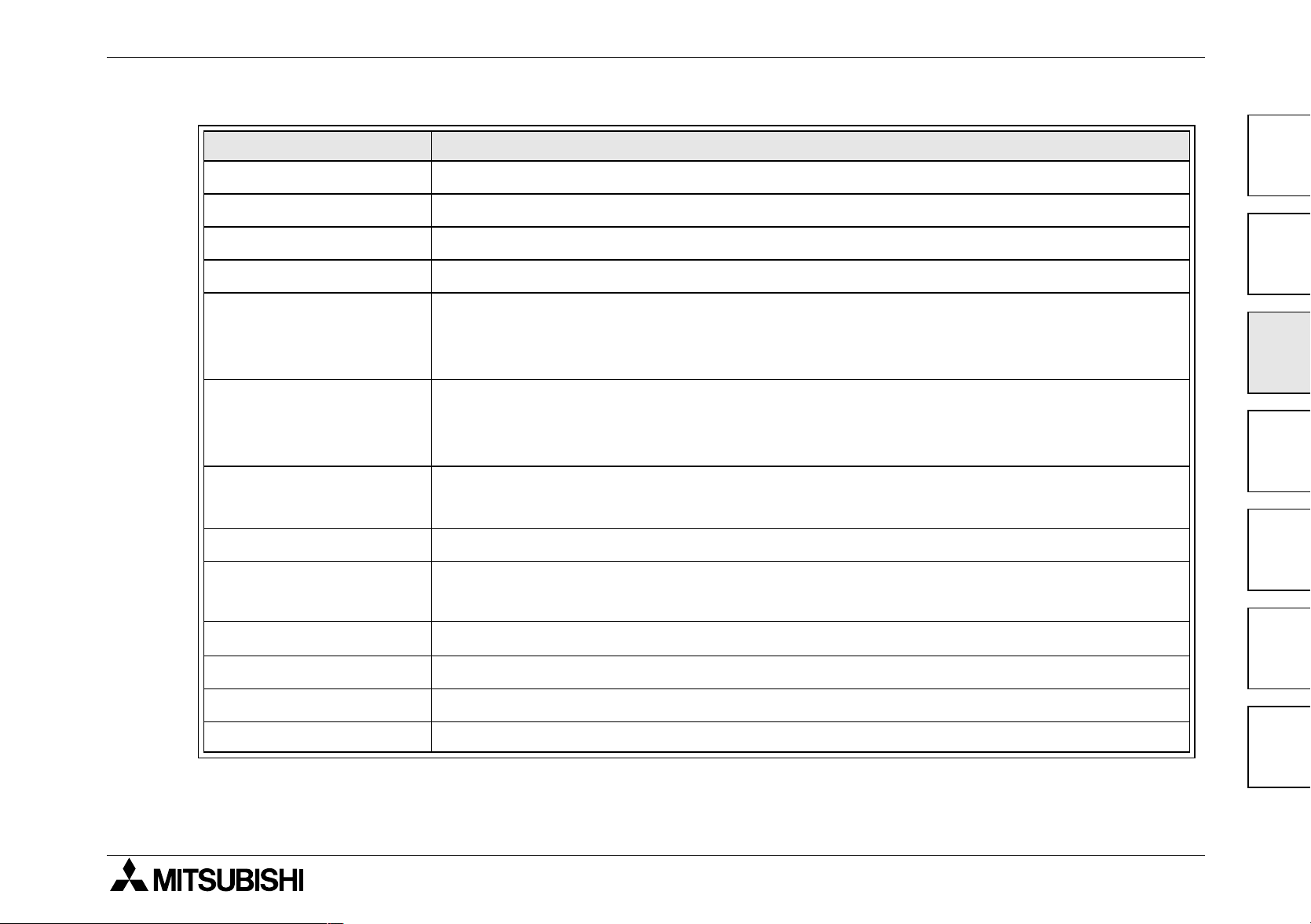
Associated Manuals
The following manuals are recommended as essential reference material for the correct operation of a
FX
series Programmable controller
1N
Manual Name Manual Number Description
FX
Programming Manual II
FX Communication
User’s Manual
1N
FX
-5DM
User’s Manual
FX-10DM-E
User’s Manual
1N
FX
-422-BD
Users Manual
1N
FX
-485-BD
Users Manual
1N
FX
-232-BD
Users Manual
.
JY992D88101
JY992D69901
JY992D84901
JY992D86401
JY992D84101
JY992D84201
JY992D84401
1S
This manual contains instruction explanation about FX
FX
1N
, FX2N and FX
2NC
Series PLC.
,
This manual contains explanation for N:N network,
parallel link, no protocol communication and computer link
This manual contains hardware explanation for
installation, specification and operation.
This manual contains hardware explanation for
installation, specification and operation.
This manual contains hardware explanation for
installation and specification.
This manual contains hardware explanation for
installation and specification.
This manual contains hardware explanation for
installation and specification.
1N
FX
-4EX-BD
Users Manual
1N
FX
-2EYT-BD
Users Manual
JY992D95001
This manual contains explanation for installation,
specification and special auxiliary relay allocation.
This manual contains explanation for installation,
JY992D95201
specification and special auxiliary relay allocation.
xiii

FX1N Series Programmable Controllers
Manual Name Manual Number Description
FX1N-2AD-BD
Users Manual
1N
FX
-1DA-BD
Users Manual
1N
FX
FX
FX
-8AV-BD JY992D84601
1N
-CNV-BD JY992D84701 This manual contains explanation for installation.
0N
-3A
User’s Manual
2N
FX
-5A
User’s Manual
2N
FX
-2DA
User’s Manual
2N
FX
-2AD
User’s Manual
JY992D96201
This manual contains explanation for installation,
specification and special auxiliary relay allocation.
This manual contains explanation for installation,
JY992D96401
specification and special auxiliary relay allocation.
This manual contains hardware explanation for
installation and specification.
This manual contains explanation for wiring, installation,
JY992D49001
specification and BFM allocation.
This manual contains explanation for wiring, installation,
JY997D11401
specification and BFM allocation.
This manual contains explanation for wiring, installation,
JY992D74901
specification and BFM allocation.
This manual contains explanation for wiring, installation,
JY992D74701
specification and BFM allocation.
2N
FX
-4DA
User’s Manual
2N
FX
-4AD
User’s Manual
2N
FX
-4AD-PT
User’s Manual
2N
FX
-4AD-TC
User’s Manual
JY992D65901
This manual contains explanation for wiring, installation,
specification and BFM allocation.
This manual contains explanation for wiring, installation,
JY992D65201
specification and BFM allocation.
This manual contains explanation for wiring, installation,
JY992D65601
specification and BFM allocation.
This manual contains explanation for wiring, installation,
JY992D65501
specification and BFM allocation.
xiv

FX1N Series Programmable Controllers
Manual Name Manual Number Description
FX2N-8AD User’s
Manual
2N
FX
-2LC User’s
Manual
2N
FX
-16LNK-M
MELSEC I/O Link
Master User’s Manual
2N
FX
-16CCL-M
CC-Link System Master
User’s Manual
2N
FX
-32CCL
CC-Link System
Interface User’s Manual
2N
FX
-64CL-M
CC-Link System Master
User’s Manual
JY992D86001
This manual contains explanation for wiring, installation,
specification and BFM allocation.
This manual contains explanation for wiring, installation,
JY992D85801
specification and BFM allocation.
This manual contains explanation for wiring, installation,
JY992D73701
setting, specification and I/O allocation.
This manual contains explanation for wiring, installation,
JY992D93101
specification and BFM allocation.
This manual contains explanation for wiring, installation,
JY992D71801
specification and BFM allocation.
This manual contains explanation for wiring, installation,
JY997D08501
specification and BFM allocation.
2N
FX
-32ASI-M
AS-interface Master
User’s Manual
JY992D76901
This manual contains explanation for wiring, installation,
specification and BFM allocation.
xv

FX1N Series Programmable Controllers
MEMO
xvi

FX1N Series Programmable Controllers
Table of Contents
Guideline ..............................................................................................ii
Associated Manuals .......................................................................... xiii
1. Introduction............................................................................................1-1
1.1 World Specification. ............................................................................................. 1-7
1.2 Model Name ....................................................................................................... 1-8
1.3 Serial Numbers ................................................................................................... 1-9
1.4 Configuration ..................................................................................................... 1-10
1.4.1 Schematic system ................................................................................................... 1-10
1.4.2 Note for Using Expansion Board ............................................................................. 1-13
1.4.3 Input/Output Points and Current Consumption ....................................................... 1-14
1.4.4 Rules of Expansion ................................................................................................. 1-18
1.5 Back up Data ..................................................................................................... 1-20
1.5.1 EEPROM backup ....................................................................................................1-20
1.5.2 Capacitor backup .................................................................................................... 1-20
2. Terminal layouts ....................................................................................2-1
2.1 AC Powered Main Units ...................................................................................... 2-1
2.2 DC Powered Main Units ...................................................................................... 2-4
0N
2.3 FX
2.4 FX2N Extension blocks ....................................................................................... 2-8
, FX2N-8E Extension blocks .......................................................................2-7
xvii

FX1N Series Programmable Controllers
3. Installation Notes...................................................................................3-1
3.1 Product Outline .................................................................................................... 3-2
3.2 FX1N RUN/STOP Control ....................................................................................3-4
3.3 General Specifications......................................................................................... 3-5
3.4 PLC Mounting Arrangements .............................................................................. 3-7
3.5 DIN Rail Mounting ............................................................................................. 3-10
3.6 Direct Mounting ................................................................................................. 3-10
3.7 Termination at Screw Terminals........................................................................ 3-14
3.8 Installing Optional Units ..................................................................................... 3-16
3.8.1 Expansion Boards ................................................................................................... 3-16
1N
3.8.2 FX
3.8.3 Extension I/O module and Special Function module............................................... 3-19
-5DM Display Module...................................................................................... 3-18
4. Power Supply ........................................................................................4-1
4.1 Wiring Techniques ...............................................................................................4-1
4.2 Wiring Cautions ................................................................................................... 4-1
4.3 Power Supply ...................................................................................................... 4-2
4.4 Power Requirements ........................................................................................... 4-3
4.5 Example Wiring ................................................................................................... 4-4
4.5.1 AC Power supply....................................................................................................... 4-4
4.5.2 24V DC Power supply ...............................................................................................4-6
4.5.3 12V DC Power Supply............................................................................................... 4-8
4.6 Service Power supply .......................................................................................... 4-9
4.7 Earthing / Grounding ........................................................................................... 4-9
xviii

FX1N Series Programmable Controllers
5. Inputs.....................................................................................................5-1
5.1 24V DC input Specifications ................................................................................5-1
5.1.1 Typical Wiring ............................................................................................................ 5-2
5.1.2 Input Circuit Connection ............................................................................................ 5-3
5.1.3 Diodes and Inputs Connected in Series .................................................................... 5-4
5.1.4 Resistors and Inputs Connected in Parallel ..............................................................5-4
5.2 AC110V Input Extension Block............................................................................5-5
5.2.1 Input Circuit Connection ............................................................................................ 5-5
5.2.2 Programming Caution ............................................................................................... 5-6
6. Outputs..................................................................................................6-1
6.1 Output Specifications........................................................................................... 6-1
6.2 Relay Output Example......................................................................................... 6-2
6.2.1 Reliability Tests ......................................................................................................... 6-3
6.3 Transistor Output Example..................................................................................6-4
6.3.1 Transistor Output Writing Diagram (Source Type) .................................................... 6-4
6.3.2 Japanese Model Transistor Output (SInk Type)........................................................ 6-4
6.3.3 Response Times ....................................................................................................... 6-5
6.4 Applying Safe Loads............................................................................................6-6
xix

FX1N Series Programmable Controllers
7. Diagnostics............................................................................................7-1
7.1 Preliminary Checks..............................................................................................7-1
7.2 ERROR LED ON (CPU ERROR) ........................................................................7-2
7.3 Common Errors ...................................................................................................7-3
7.4 Maintenance ........................................................................................................ 7-3
7.5 Operation and Error Flags ...................................................................................7-4
7.6 PLC Status Registers .........................................................................................7-5
7.7 Error Registers .................................................................................................... 7-6
7.8 Error Codes ......................................................................................................... 7-7
7.9 Instruction List ..................................................................................................... 7-8
7.10 Device List ........................................................................................................ 7-11
xx

FX1N Series Programmable Controllers
1 INTRODUCTION
2 TERMINAL LAYOUTS
3 INSTALLATION NOTES
4 POWER SUPPLY
5 INPUTS
1
2
3
4
5
6OUTPUTS
7 DIAGNOSTICS
6
7

FX1N Series Programmable Controllers
1 INTRODUCTION
2 TERMINAL LAYOUTS
3 INSTALLATION NOTES
4 POWER SUPPLY
5 INPUTS
6OUTPUTS
7 DIAGNOSTICS

FX1N Series Programmable Controllers
1. Introduction
Introduction 1.
This manual covers hardware installation instructions for the FX1N Series PLC.
1N
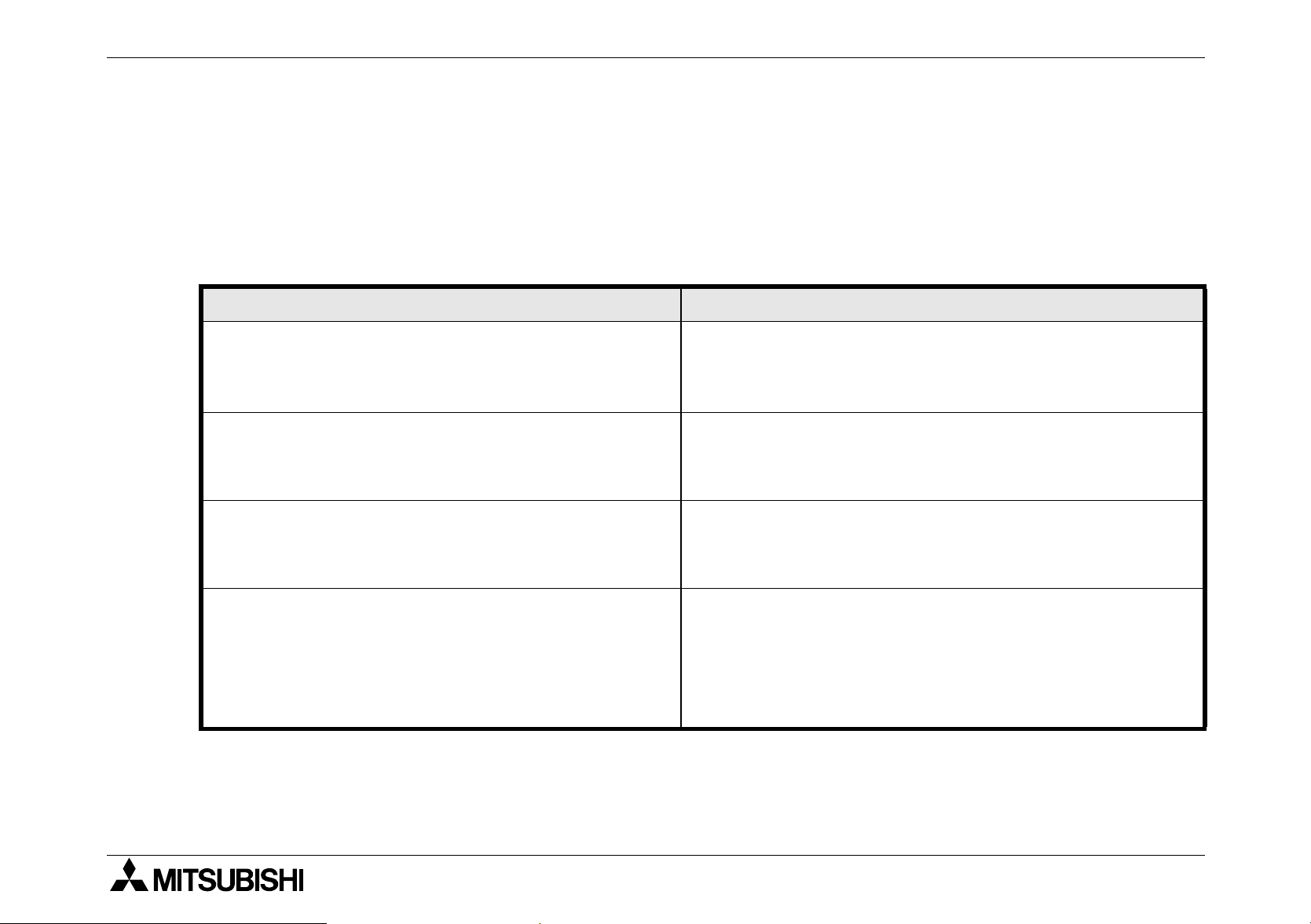
Table 1.1: FX
MODEL
FX1N-14MR-ES/UL
FX1N-14MT-ESS/UL
FX1N-24MR-ES/UL
FX1N-24MT-ESS/UL
FX1N-40MR-ES/UL
FX1N-40MT-ESS/UL
FX1N-60MR-ES/UL
FX1N-60MT-ESS/UL
FX1N-14MR-DS
FX1N-14MT-DSS Transistor
Main Modules
INPUT OUTPUT
QTY TYPE QTY TYPE
8
14
(16)
24 16
36
(40)
8
24V DC
Source
Sink/
6
(8)
10
(16)
24
6
(8)
Relay
Transistor
Relay
Transistor
Relay
Transistor
Relay
Transistor
Relay
POWER
SUPPLY
100-240 VAC
+10%
-15%
50/60Hz
DIMENSIONS
mm (inches)
90
(3.55)
90
(3.55)
130
(5.12)
175
(6.89)
90
(3.55)
90
(3.55)75(2.96)
WEIGHT
kg (lbs)
0.45
(0.99)
0.45
(0.99)
0.65
(1.43)
0.80
(1.76)
0.45
(0.99)
1
2
3
4
5
FX1N-24MR-DS
FX1N-24MT-DSS Transistor
FX1N-40MR-DS
FX1N-40MT-DSS Transistor
FX1N-60MR-DS
FX1N-60MT-DSS Transistor
14
(16)
24 16
36
(40)
24V DC
Sink/
Source
(16)
10
24
Relay
Relay
Relay
12V DC
-15%
to
24V DC
+20%
Note: Occupied points are shown in brackets for input and outputs.
90
(3.55)
130
(5.12)
175
(6.89)
90
(3.55)75(2.96)
1-1
0.45
(0.99)
0.65
(1.43)
0.80
(1.76)
6
7

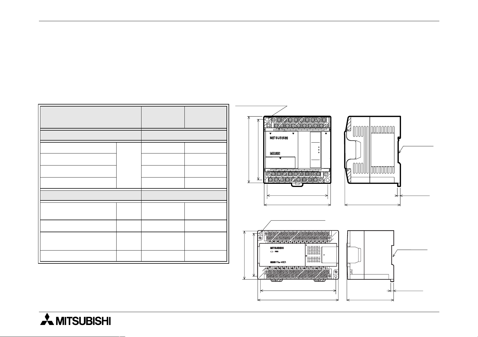
FX1N Series Programmable Controllers Introduction 1.
Figure 1.1 :Main unit outline
2 - φ4.5 (0.17'')
82 (3.23'')
90 (3.55'')
24V
L
0V
COM0 COM1
X1
S/S
N
Y0
Y1
X0 X2
COM2
X3 X5
Y2
Y3
COM3
X7
COM4
X11
X6
X10
0123
4567
14 15
FX1N-24MR
0123
4567
Y10Y5
Y6
Y7
X4
Y4
POWER
RUN
ERROR
1110
X15
X1
X12
X14
131110 12
IN
OUT
Y11
W - 8 (0.32'')
W
75 (2.96'')
Please see the previous page for each units width measurement.
UNITS: mm (inches)
27.3(1.08")
DIN rail
mounting
slot
27.3(1.08")
8 (0.32'')
1-2
FX1N Series Programmable Controllers Introduction 1.
Table 1.2: Powered Extension Units
MODEL
FX0N-40ER-ES/UL
FX0N-40ET-DSS
FX0N-40ER-DS
FX2N-32ER-ES/UL
FX2N-32ET-ESS/UL
FX2N-48ER-ES/UL
FX2N-48ET-ESS/UL
FX2N-48ER-UA1/UL
INPUT OUTPUT
QTY TYPE QTY DEVICE
24
24 16
24V DC
24 16 Relay
16 16 Relay
16 16
24 24 Relay
24 24
24 110VAC 24 Relay
Sink/
Source
16 Relay
Transistor
(Source)
Transistor
(Source)
Transistor
(Source)
POWER
SUPPLY
100-
240VAC
+10%,
-15%
50/60Hz
24VDC
+20%
-15%
100-
240VAC
+10%,
-15%
50/60Hz
100-
240VAC
+10%,
-15%
50/60Hz
DIMENSIONS
mm (inches)
150
(5.91)
90
150
(5.91)
182
(7.17)
220
(8.67)
(3.55)87(3.43)
WEIGHT
kg (lbs)
0.75
(1.65)
0.65
(1.43)
0.85
(1.87)
1.00
(2.2)
1
2
3
4
5
6
1-3
7

FX1N Series Programmable Controllers Introduction 1.
Table 1.3: Extension blocks
MASS
(WEIGHT)
kg (lbs)
MODEL
INPUT OUTPUT
QTY TYPE QTY DEVICE TYPE
DIMENSIONS
mm (inches)
FX0N-8EX-UA1/UL
110V
FX
2N
-8EX-UA1/UL
8
AC
-- -
inputs
FX0N-8EX-ES/UL
FX
2N
-8EX-ES/UL
8
24V DC
-- -
Sink/
FX0N-8ER-ES/UL
2N
FX
-8ER-ES/UL
44
Source
-
Relay
FX0N-8EYR-ES/UL
--8 -
2N
FX
-8EYR-ES/UL
FX0N-8EYT-ESS/UL
- - 8 Transistor Source
2N
FX
-8EYT-ESS/UL
24V DC
FX0N-16EX-ES/UL 16
Sink/
-- -
Source
FX0N-16EYR-ES/UL - - 16 Relay FX0N-16EYT-ESS/UL - - 16 Transistor Source
43
(1.70)
70
(2.76)
0.2
(0.44)
90
(3.55)87(3.43)
0.3
(0.66)
24V DC
FX2N-16EX-ES/UL 16
Sink/
-- -
Source
FX2N-16EYR-ES/UL - - 16 Relay FX2N-16EYT-ESS/UL - - 16 Transistor Source
40
(1.58)90(3.55)87(3.43)
0.3
(0.66)
1-4

FX1N Series Programmable Controllers Introduction 1.
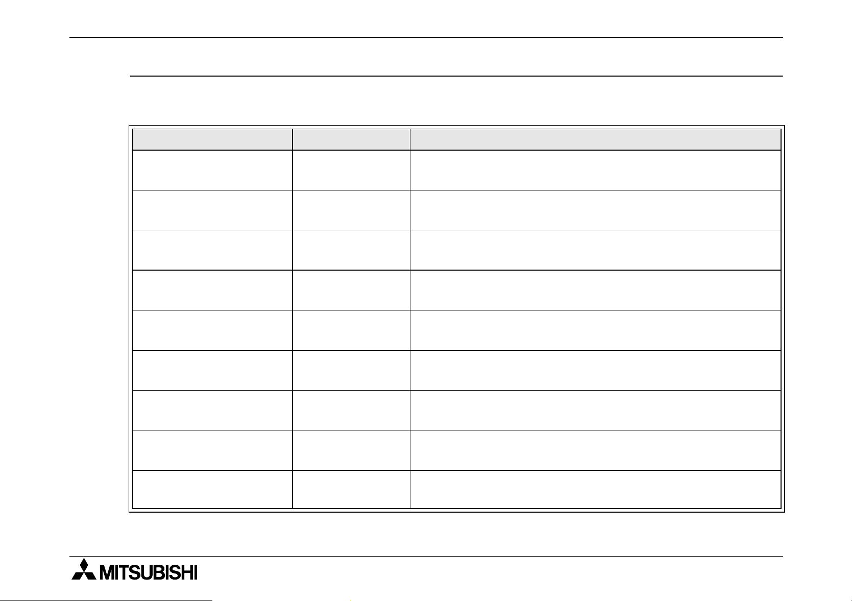
Table 1.4: Special function blocks
MODEL DESCRIPTION
FX0N-3A Analog / Digital converter 43 (1.70)
FX2N-5A Analog / Digital converter 55 (2.17) 0.3 (0.66)
FX2N-2DA Digital to analog converter
43 (1.70) 0.2 (0.44)
FX2N-2AD Analog to digital converter
FX2N-4DA Digital to analog converter
FX2N-4AD Analog to digital converter
55 (2.17)
FX2N-4AD-PT PT 100 probe interface
FX2N-4AD-TC Thermo-couple interface
FX2N-8AD Analog input interface 75 (2.96) 75 (2.96)
FX2N-2LC Temperature Control 55 (2.17)
FX2N-16LNK-M
FX2N-16CCL-M CC-Link master 0.4 (0.88)
MELSEC I/O LINK
Remote I/O system master
43 (1.70)
DIMENSIONS
mm (inches)
87 (3.43)
90 (3.5)
87 (3.43)
MASS
kg (lbs)
0.2 (0.44)
0.3 (0.66)
0.5 (1.1)
(WEIGHT)
1
2
3
4
5
FX2N-32CCL CC-Link interface 0.2 (0.44)
FX2N-64CL-M CC-Link/LT master 0.15 (0.33)
FX2N-32ASI-M AS-interface master 55 (2.17) 0.2 (0.44)
1-5
6
7
FX1N Series Programmable Controllers Introduction 1.
Table 1.5 :Expansion Board and Communication Adapter
MODEL DESCRIPTION DIMENSIONS
FX
-4EX-BD Four point special input
1N
FX
-2EYT-BD Two point special output
1N
-2AD-BD Two channel special analog to digital converter
FX
1N
-1DA-BD One channel special digital to analog converter
FX
1N
-232-BD RS-232C communication interface
FX
1N
-422-BD RS-422 communication interface
FX
1N
-485-BD RS-485 communication interface
FX
1N
-8AV-BD Analog potentionmeter
FX
1N
-CNV-BD Communication adapter connection interface
FX
1N
FX
FX
FX
-232ADP
2NC
-232ADP
0N
-485ADP
2NC
*1
*1
*1
RS-232C commuication adapter
RS-232C commuication adapter
RS-485 commuication adapter
Mounts directly into
top of PLC
19.1
(0.76)
43
(1.70)
19.1
(0.76)
90
(3.55)
85
(3.35)
68
(2.68)
78
(3.08)
MASS (WEIGHT)
kg (lbs)
Mounts directly
into top of PLC
0.1 (0.22)
FX
-485ADP
0N
*1
RS-485 commuication adapter
43
(1.70)
87
(3.43)
0.3 (0.66)
*1 The communication adapter needs to connect via an FX1N-CNV-BD to the FX1N Series
PLC.
1-6

FX1N Series Programmable Controllers Introduction 1.
1.1 World Specification.
Table 1.6: World Specification
Input
Sink / Source
Outputs
Transistor
World spec models : SINK / SOURCE.
Japanese models : ALWAYS SINK.
World spec models : ALWAYS SOURCE.
Japanese models : ALWAYS SINK.
1
2
3
4
5
1-7
6
7
FX1N Series Programmable Controllers Introduction 1.
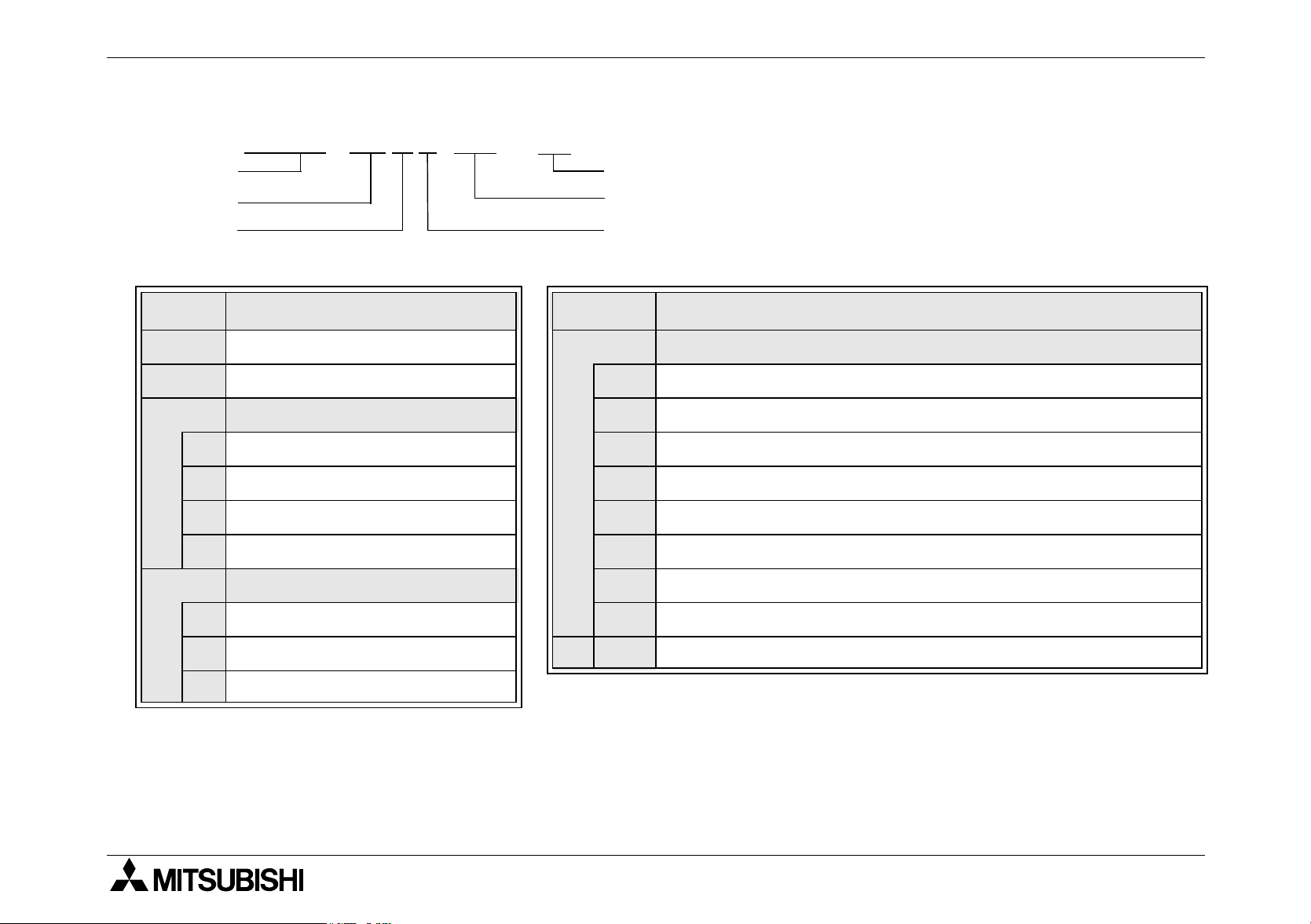
1.2 Model Name
FX
A)
B)
C)
-24MR-DS /
1N
F)
E)
D)
Table 1.7 :Notes on model name
Ref. Description Ref. Description
A)
B)
C)
PLC type: FX
Total number of I / O channels
Unit type
M MPU - main unit DS DC World spec, CE & UL registered.
E Powered extension unit DSS DC World spec, DC source transistor, CE & UL registered.
EX Extension block, input E AC, Japanese spec.
EY Extension block, output ES AC, World spec, CE registered.
Output type
1N
Features
Omit AC, Japanese spec.
D DC Japanese spec.
E)
ESS AC World spec, DC source transistor, CE registered.
D)
RRelay UA1 AC Power Supply, AC inputs, CE registered.
TTransistor
STriac (SSR)
*1. The FX
40ET-DSS and FX
0N-
F)
40ER-DSS FX0N series extension units do not have UL certi-
0N-
UL UL registered
fication.
1-8

FX1N Series Programmable Controllers Introduction 1.
1.3 Serial Numbers
SERIAL NO.: 0 6 3267
1)
e.g.
0=2000
1=2001
Table 1.8 : Notes on serial numbers
1)
2)
3)
2)
1 - 9 = Jan - Sept
X= Oct
Y= Nov
Z= Dec
Production year
Production month
Production serial number
1
3)
2
3
4
5
1-9
6
7

FX1N Series Programmable Controllers Introduction 1.
1.4 Configuration
1.4.1 Schematic system
FX1N-2AD-BD*1 FX1N-1DA-BD
FX1N-4EX-BD*1 FX1N-2EYT-BD
FX1N-232-BD FX1N-422-BD
-485-BD
FX
1N
-8AV-BD
FX
1N
-CNV-BD + FX
FX
1N
-CNV-BD + FX0N-232ADP
FX
1N
-CNV-BD + FX
FX
1N
-CNV-BD + FX0N-485ADP
FX
1N
-232ADP
2NC
-485ADP
2NC
1
FX1N-5DM
-EEPROM-8L
FX
1N
*2
GX Developer
FX-PCS/WIN-E
GX IEC Developer
FX-PCS/AT-EE
MELSEC MEDOC
RS-232C/RS-422 Converter
FX-232AW FX-232AWC
FX-232AWC-H
*1
B
*1
C
D
FX1N-14MR-ES/UL
-24MR-ES/UL
FX
1N
-40MR-ES/UL
FX
1N
-60MR-ES/UL
FX
1N
-14MT-ESS/UL
FX
1N
-24MT-ESS/UL
FX
1
1'
1N
-40MT-ESS/UL
FX
1N
-60MT-ESS/UL
FX
1N
-14MR-DS
FX
1N
-24MR-DS
FX
1N
-40MR-DS
FX
1N
-60MR-DS
FX
1N
-14MT-DSS
FX
1N
-24MT-DSS
FX
1N
-40MT-DSS
FX
1N
-60MT-DSS
FX
1N
1" 2
A
FX2N-32ER-ES/UL
-40ER-ES/UL
FX
0N
-48ER-ES/UL
FX
2N
-32ET-ESS/UL
FX
2N
-48ET-ESS/UL
FX
2N
-40ER-DS
FX
0N
-40ET-DSS
FX
0N
-48ER-UA1/UL
FX
2N
3
GOT-900 Series
FX-10DM-E
FX-10DU-E
*3
H
FX-50DU-TKS-E
E
FX-40DU-TK-ES
FX-40DU-ES
FX-30DU-E
FX-20P-E (-SET0)
F
FX-10P-E
G
FX-25DU-E
FX-20DU-E
H'
FX0N-8EX-UA1/UL
FX0N-8EX-ES/UL
FX0N-8ER-ES/UL
FX0N-8EYR-ES/UL
-8EYT-ESS/UL
FX
0N
FX2N-8EX-UA1/UL
FX2N-8EX-ES/UL
FX2N-8ER-ES/UL
2N
-8EYR-ES/UL
FX
FX2N-8EYT-ESS/UL
K
FX0N-16EX-ES/UL
-16EYR-ES/UL
FX
0N
FX0N-16EYT-ESS/UL
FX2N-16EX-ES/UL
FX2N-16EYR-ES/UL
-16EYT-ESS/UL
FX
2N
FX0N-3A
FX2N-2DA FX2N-2AD
-4DA FX2N-4AD
FX
2N
FX2N-4AD-PT
FX2N-4AD-TC
FX2N-8AD FX2N-5A
-2LC
FX
2N
FX2N-16LNK-M
FX2N-64CL-M
FX2N-16CCL-M
-32CCL
FX
2N
FX2N-32ASI-M
J
I
1-10

FX1N Series Programmable Controllers Introduction 1.
*1 Available for use with FX1N version 2.00 or later.
*2 When using the FX
1N
-EEPROM-8L with an expansion board in group C, only the loader
function (transfer program) can be used. Remove it from the PLC after operating the
loader function and attach the top cover into the PLC.
*3 GOT-F900 Series can connect via an FX
*4 When supplying 24V DC power source to the FX
1N
-232-BD to the FX1N PLC.
1N
main unit, only the FX0N series
powered extension unit (DC power supply type) can connect.
1N
When supplying 12V DC power source to the FX
main unit, the powered extension unit
and special function blocks cannot connect to it.
*5 FX
1N
series PLC cannot connect together with an FX2N-32ASI-M and FX2N-16CCL-M.
An FX2N-32ASI-M module cannot be attached to an FX1N series PLC that is using an
2N
FX
-16CCL-M module. Only one FX2N-32ASI-M module can be connected to the PLC.
1
2
3
4
5
1-11
6
7

FX1N Series Programmable Controllers Introduction 1.
Table 1.9 : Configuration Notes
A
FX
B
FX
C
FX
D
Memory Cassette or Display Module
E
Programming Software
F
RS-232C/RS-422 Converter for PC
G
Dedicated Programming Tools
Series Main Unit
1N
Expansion Boards for Analog I/O
1N
Expansion Boards without Analog I/O
1N
Table 1.10: Connection Ports
1
Left hand side port
Left hand side port + FX
or
Left hand side port + FX
+ FX
2NC
-232ADP
1'
or
Left hand side port + FX
0N
+ FX
-232ADP
1N
1N
1N
-232-BD
-CNV-BD
-CNV-BD
H
H’
I
J
K
1"
2
3
HMI Devices
(GOT-F900/ GOT-A900/ DM/ DU)
<GOT: Graphic Operation Terminal,
DM: Display Module,
DU: Data access Unit>
DU Series
(Discontinued since Sept. 2002)
Powered Extension Units
Extension Blocks
Special Function Blocks
1N
Left hand side port + FX
-422-BD
Programming Port
Extension Bus Port
1-12

FX1N Series Programmable Controllers Introduction 1.
1.4.2 Note for Using Expansion Board
1S
The following conditions cannot be accomplished with an FX
-FX
-FX
-FX-10DM + FX
- Connect two Programming tools (FX-10P-E, FX-20P-E, Programming software, etc.)
- The use of Special function Blocks
1N
-422-BD + FX-2PIF
1N
-5DM + FX1N-422-BD + FX-10DM
1N
-422-BD + FX-10DM
PLC.
Caution
Connect a programming tool (such as an FX-10P-E, FX-20P-E and personal computer) to
either the connector built in to the PLC or the connector on the FX1N-422-BD or FX1N-232BD. If a programming tool is connected to both connectors, the program stored in the PLC
may not match the program stored in the programming tool. If the program is changed or the
set value of timers or counters are changed with this configuration, the program may be partially overwritten and the PLC may malfunction.
1
2
3
4
5
1-13
6
7

FX1N Series Programmable Controllers Introduction 1.
1.4.3 Input/Output Points and Current Consumption
0N
The following tables show the input/output points of various types of FX
and FX2N series
extension blocks, and special function blocks, along with the special function block current
consumption.
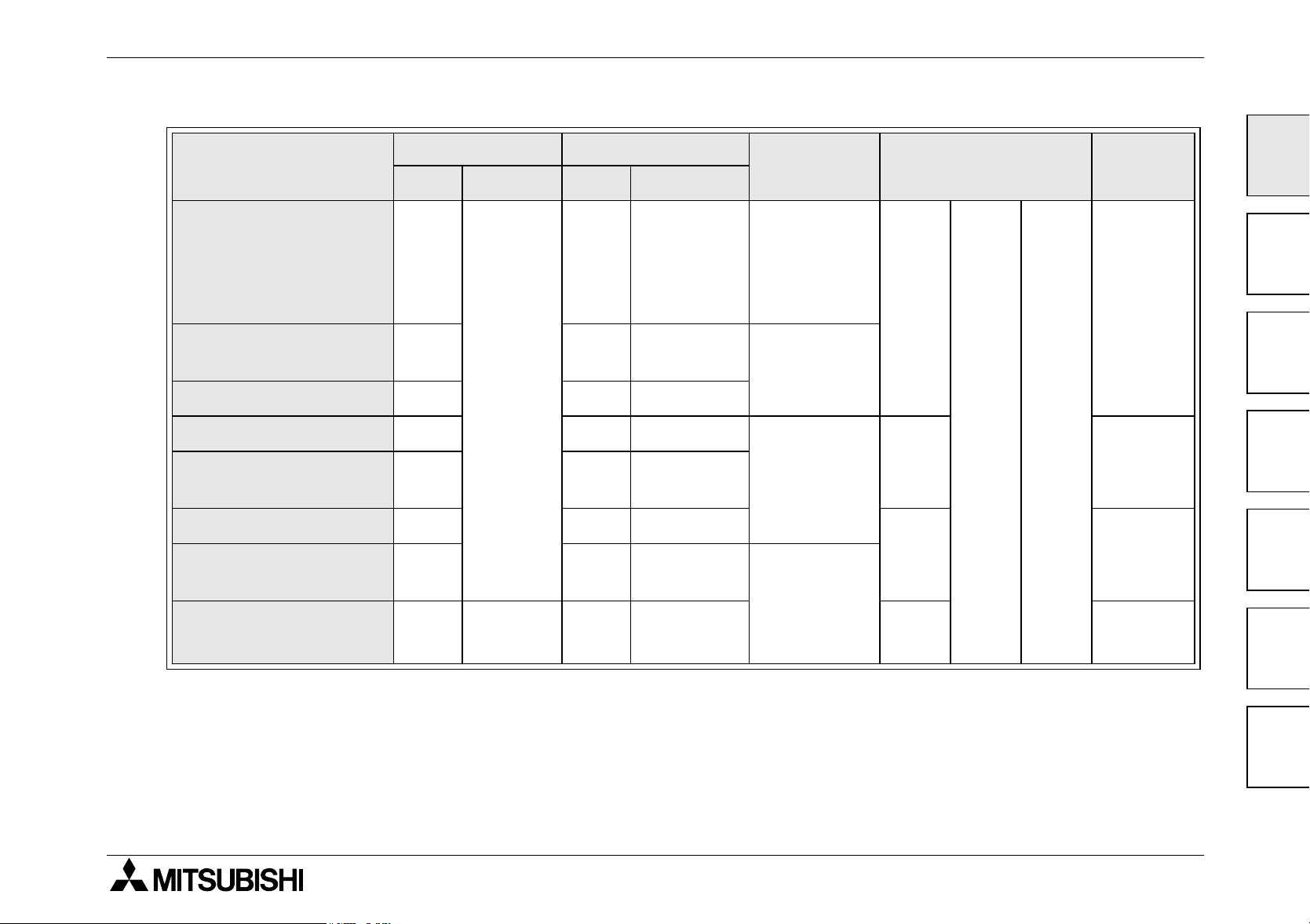
Table 1.11: Extension blocks
FX
FX
FX
FX
FX
FX
FX
FX
MODEL
0N
-8ER-ES/UL
2N
-8ER-ES/UL
0N
-8EX-ES/UL
2N
-8EX-ES/UL
0N
-8EX-UA1/UL
2N
-8EX-UA1/UL
0N
-8EYR-ES/UL
2N
-8EYR-ES/UL
*1 8 points are used for actual input/output, however, this block should occupy 16 input/
output points.
INPUTXOUTPUT
Y
4(8) 4(8)
TOTAL MODEL
*1
16
8-8
8-8
-88
FX0N-8EYT-ESS/UL
2N
FX
FX
FX
FX
FX
FX
FX
-8EYT-ESS/UL
0N
-16EX-ES/UL 16 - 16
0N
-16EYT-ESS/UL - 16 16
0N
-16EYR-ES/UL - 16 16
2N
-16EX-ES/UL 16 - 16
2N
-16EYR-ES/UL - 16 16
2N
-16EYT-ESS/UL - 16 16
INPUTXOUTPUT
Y
TOTAL
-88
1-14

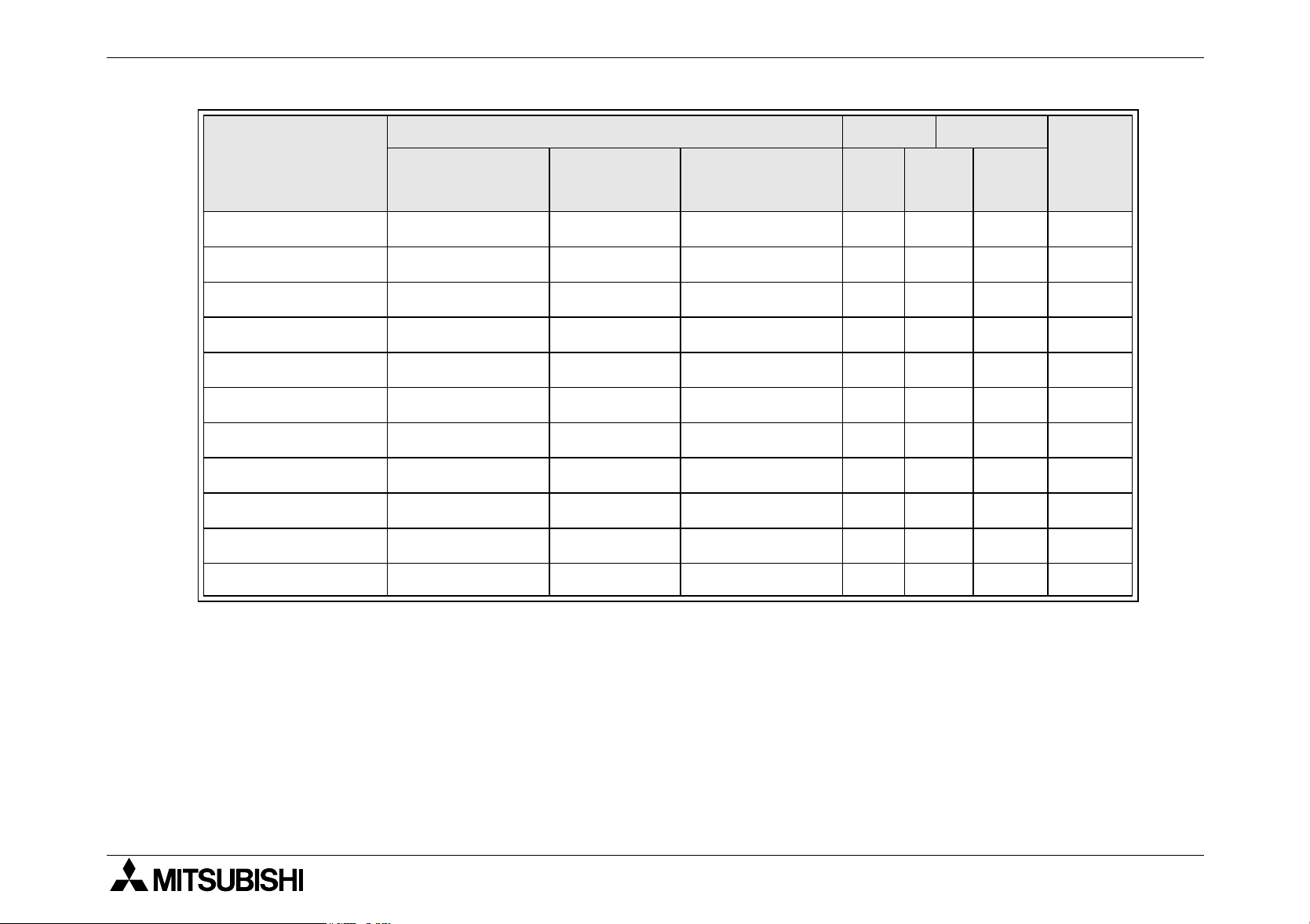
FX1N Series Programmable Controllers Introduction 1.
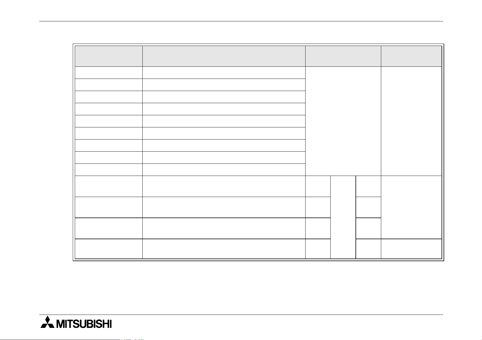
Table 1.12: Special function block/Function adapters/Expansion board
CURRENT CONSUMPTION INPUT OUTPUT
FX
FX
FX
FX
FX
FX
FX
FX
MODEL
0N
-3A 30mA 90mA - - 8 - 8
2N
-5A 70mA - 90mA - 8 - 8
2N
-2DA 30mA 85mA - - 8 - 8
2N
-2AD 20mA 50mA - - 8 - 8
2N
-4AD 30mA - 55mA - 8 - 8
2N
-4DA 30mA - 200mA - 8 - 8
2N
-4AD-PT 30mA - 50mA - 8 - 8
2N
-4AD-TC 30mA - 50mA - 8 - 8
INTERNAL 5V
DC
INTERNAL
24V DC
EXTERNAL
24V DC
X X/Y Y
TOTAL
1
2
3
4
FX
FX
FX
FX
FX
FX
FX
FX
FX
2N
-8AD 50mA - 80mA - 8 - 8
2N
-2LC 70mA - 55mA - 8 - 8
*1
2N
-16CCL-M
2N
-32CCL 130mA - 50mA - 8 - 8
2N
-64CL-M 190mA - 25mA
2N
-16LNK-M 200mA - 90mA *4 *4
2N
-32ASI-M
0N
-232ADP 200mA - - - - - -
0N
-485ADP 30mA - 50mA - - - -
*1
Self supplied - 150mA *2 *2
150mA - 70mA
*3
*5
*3 *3
*6 *6
5
6
7
1-15
FX1N Series Programmable Controllers Introduction 1.
Table 1.12: Special function block/Function adapters/Expansion board
CURRENT CONSUMPTION INPUT OUTPUT
FX
FX
FX
FX
FX
FX
FX
FX
FX
FX
FX
MODEL
2NC
-232ADP 100mA - - - - - -
2NC
-485ADP 150mA - - - - - -
1N
-4EX-BD - - 25mA - - - -
1N
-2EYT-BD - - - - - - -
1N
-2AD-BD - - - - - - -
1N
-1DA-BD-------
1N
-232-BD 20mA - - - - - -
1N
-422-BD 120~220mA - - - - - -
1N
-485-BD 60mA - - - - - -
1N
-8AV-BD - - - - - - -
1N
-CNV-BD-------
INTERNAL 5V
DC
INTERNAL
24V DC
EXTERNAL
24V DC
X X/Y Y
TOTAL
*1 FX1N series PLC cannot connect together with an FX2N-32ASI-M and FX2N-16CCL-M.
An FX2N-32ASI-M module cannot be attached to an FX1N series PLC that is using an
2N
FX
-16CCL-M module. Only one FX2N-32ASI-M module can be connected to the PLC.
1-16

FX1N Series Programmable Controllers Introduction 1.
*2 Maximum number of I/O points per system Connection is allowed as far as the following
condition is satisfied:
(Actual number of I/O points of PLC) + (Number of points occupied by special extension
2N
blocks) + (Number of points occupied by FX
O modules) ≤ 128
Moreover, if connecting two or more FX
connect to the “remote I/O modules” and “remote device modules” but subsequent
modules only connect to “remote device modules”.
*3 For details, refer to FX
*4 The value depends on the switch setting (16, 32, 48, 64, 96 or 128 points).
*5 FX
*6 The I/O control points of both the FX
2N
-32ASI-M must be supplied 70mA (at Typical 30.5V) from the AS-interface power
supply.
points. Therefore, there is a limitation in the number of units (number of slaves) which
can be controlled according to the I/O points recognized by the PLC's CPU (occupation).
Occupation I/O points: Each AS- i slave station occupies 4 CPU I/ O points.
2N
-64CL-M User’s Manual.
2N
-32ASI-M and PLC CPU must not exceed 128
-16CCL-M: 8) + (32 x Number of remote I/
2N
-16CCL-M, the first master module can
1
2
3
4
5
1-17
6
7

FX1N Series Programmable Controllers Introduction 1.
1.4.4 Rules of Expansion
1N
The maximum I/O for an FX
system is 128 I/O points and 8 special function blocks.
The FX1N Series can be expanded as follows when used independently.
- 2 special function blocks
- 1 special function block and up to 16 I/O points
- Up to 32 I/O points
It can also be expanded to 4 special function blocks when used in conjunction with an FX
extension unit (2+2). An AC powered FX1N can be expanded by 8 special function blocks when
used in conjunction with an FX2N extension unit (2+6).
X000~X043 X050~X057
FX0N-232ADP
POWER
RD
SD
Y000
FX0N-232ADP FX1N-60MR-ES/UL FX0N-16EX-ES/UL
X070
X1
COM
X3 X5X4X7X6X11 X15
X0 X2
LN
Y1
Y0
COM
24+
COM0
COM Y0Y1Y2 Y4Y6 Y0Y2 Y4Y6
Y4
Y2
COM2
COM3
COM1
Y5
Y3
Y027
~
X117
~
X1
X5 X7X6X1
COM COM X1
X0 X2X3X4
N X0 X2 X4 X6L
POWER
-40ER
FX
0N
X17
X13 X43
X21
X22
X14 X16
X20
Y14
Y10
Y12
Y11
COM4
Y15
Y13 COM5
X5 X7
X6
IN
01234567
01234567
01234567
OUT
07654321
01234567
Y6
X10
Y7
X0 X2X3X4
X23 X25
Y16
X27
X31
X33
X35
X37
X41
X32
0123
10 11 12 13 14 15 16 17
30 31 32 33
40 41 42 43
0123
Y22
Y23 Y25
X42X12
X34
X36
X40
4567
272524 2620 21 22 23
373534 36
IN
POWER
RUN
ERROR
FX1N-60MR
OUT
4567
1716
14 1510 11 12 13
272624 2520 21 22 23
Y26
Y24
COM7
Y27
FX0N-8EYR
OUT
4765
POWER
3210
X060
24+X1X3X5X7
X0 X2 X4 X6
FX0N-16EX
POWER
60
770IN11223344556
X0X1X2 X4 X6
X3 X5 X7
~
X067
X26
X30
X24
Y20
Y17
Y21
COM6
X7X3 X5
Y7COM0 COM1 COM2 Y3 COM3 Y5 Y7 COM4 Y1 Y3 COM5 Y524+
1N
•FX
series PLC cannot connect together with
an FX2N-32ASI-M and FX2N-16CCL-M.
2N
An FX
-32ASI-M module cannot be attached to
an FX1N series PLC that is using an FX2N16CCL-M module.
2N
Only one FX
-32ASI-M module can be
connected to the PLC.
2N
• If connecting two or more FX
-16CCL-M, the
first master module can connect to the “remote I/
O modules” and “remote device modules” but
subsequent modules only connect to “remote
0N
Y030
Y047
~
FX0N-40ER-ES/UL
Y050
~
Y057
device modules”.
FX0N-8EYR-ES/UL
1-18

FX1N Series Programmable Controllers Introduction 1.
• If a DC powered main unit is used with a power supply of less than 24VDC -15% (20.4V DC
or less), then it
extension units.
It can accommodate a maximum of an additional 32 I/O points.
• If an FX
above, as it utilizes special M coils for its operation and therefore does not contribute to the
maximum 128 I/O point count. Only one special function board can be used at any time.
See section 3.9.1 for more details.
expansion board is being used, it does not alter the rules of expansion outlined
1N
cannot
be fully expanded by using special function blocks or powered
1
2
3
4
5
1-19
6
7

FX1N Series Programmable Controllers Introduction 1.
1.5 Back up Data
1.5.1 EEPROM backup
Data includes the Program, Comment, File Registers (D1000 ~ D7999), and parameter data.
This will be stored as long as the EEPROM is not damaged. Mitsubishi Electric has
guaranteed a life cycle time of 10,000 writes to the EEPROM memory. Users may experience
operational writes to the EEPROM in excess of 10,000; however, due to temperature effects a
quantitative estimation cannot be given.
If the PLC has been powered on for five minutes or more, the following device data will be
saved in the EEPROM at powerdown:
S0 ~ S127, M384 ~ M511, C16 ~ C31, C235 ~ C255, and D128 ~ D255.
1.5.2 Capacitor backup
The capacitor backed memory includes M512 ~ M1535, S128 ~ S999, T246 ~ T255,
C32 ~ C199, C220 ~ C234, D256 ~ D7999 and the RTC.
The capacitor backed memory will retain data for a maximum of 10 days (Ambient
temperature: 25 °C), and requires 30 minutes to recharge upon power up.
1N
Note
: The FX
does not have battery backup, if a system requires backup of more than 10
days (Ambient temperature: 25 °C), a peripheral backup power source must be provided.
1-20
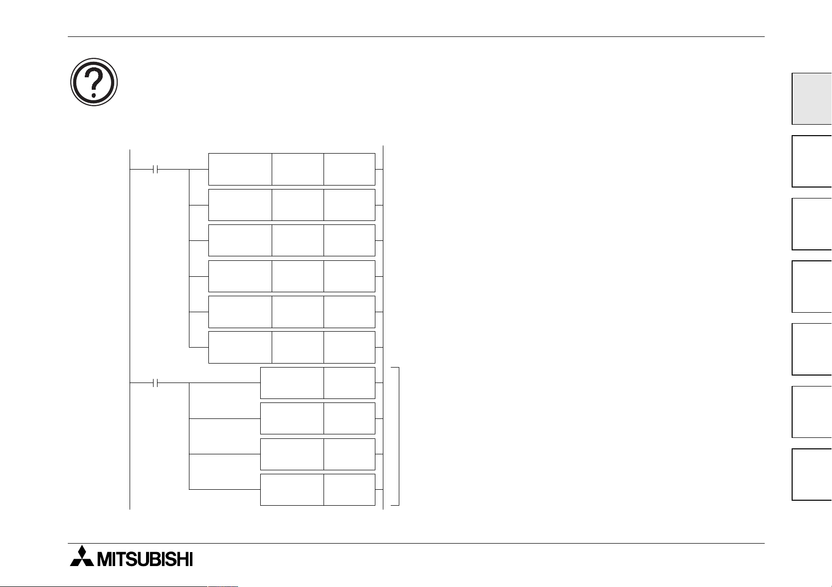
FX1N Series Programmable Controllers Introduction 1.
Warning
If the PLC will be intentionally powered down for a duration exceeding 10days (Ambient
temperature: 25 °C), then please include the following code into the user program as the
supercapcitor backed area of memory will be unfixed.
The device data held by the
M8002
M8001
FNC 40
ZRST
FNC 40
ZRST
FNC 40
ZRST
FNC 40
ZRST
FNC 40
ZRST
FNC 40
ZRST
D256 D7999
M512 M1535
S128 S999
T246 T255
C32 C199
C220 C234
RST T246
supercapcitor will not be reset to 0
as there is NO internal hardware
reset function.
However, initialization method by
the ZRST instruction, for capacitor
backed devices (T246 ~ T255,
C32 ~ C199, C220 ~ C234) can
not be initialized. In order to
initialize the condition of the reset
coil, execute in OFF the RST
instruction of the corresponding
device currently used into the user
program as shown in the example
1
2
3
4
5
RST T247
RST C32
RST C33
The capacitor
backed device
currently used
into the user
program.
program on the left.
6
7
1-21

FX1N Series Programmable Controllers Introduction 1.
MEMO
1-22

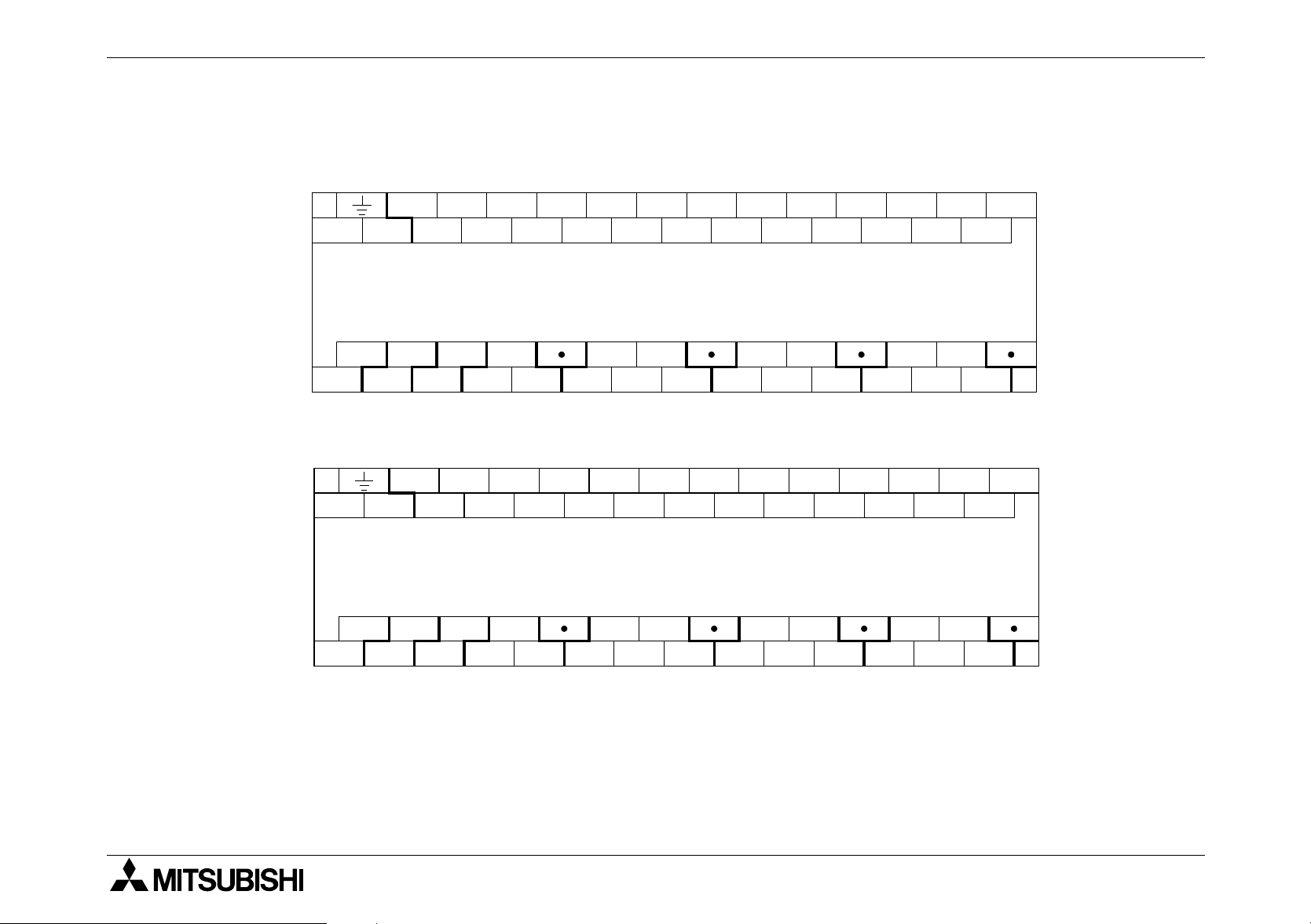
FX1N Series Programmable Controllers
2. Terminal layouts
The following selection of terminal layouts are taken from the FX1N product range.
Note: All layouts are schematic only and are intended to aid the creation of wiring diagrams.
Terminal layouts 2.
1
2.1 AC Powered Main Units
S/S X1
L
N X0 X4
X2
FX1N-14MR-ES/UL
0V Y0 Y1 Y2 Y3
COM0 COM1 COM3COM2
24V
S/S
X0 X4
NL
X1
X3
X2
FX1N-14MT-ESS/UL
X3
X5
X5
X7
X6
Y4
COM4 COM5
X7
X6
Y5
S/S X1
L
N X0 X4
X3
X2
FX1N-24M R-ES/UL
0V Y0 Y1 Y2 Y3
COM0 COM1 COM3COM2
24V
S/S X1
L
X0 X4
N
X3
X2
FX1N-24MT-ESS/UL
X5
X5
X6
X6
X7
Y5
COM4
X7
X10
Y6Y4Y10
X10
X13X11
X12
X12
X14
Y7 Y11
X13X11
X14
2
X15
3
4
5
X15
6
24V
0V
Y0 Y1 Y2 Y3
+V0 +V1 +V3+V2
Y4
+V4 +V5
Y5
0V Y0 Y1 Y2 Y3
24V
Y5
Y6 Y10
Y7 Y11+V0 +V1 +V2 +V3 Y4 +V4
2-1
7
FX1N Series Programmable Controllers Terminal layouts 2.
S/S X1
L
N X0 X4
FX1N-40MR-ES/UL
0V Y0 Y1 Y2
COM0 COM1 COM3COM2
24V
S/S X1
L
X0 X4
N
FX1N-40MT-ESS/UL
0V Y0 Y1 Y2
24V
X2
X2
X3
X3
Y3
X5
X5
X6
X6
X7
X7
X13X11
X10
X12
Y6Y4 Y14
Y5
X10
Y5
Y7 Y11
X12
Y6Y4 Y14
Y7 Y11
X14
COM4
X13X11
X14
X15
X16
X20
Y10 Y12
Y13
X15
X16
Y10 Y12
X21X17
X21X17
X20
Y13
X23
X22 X24
COM5
X22 X24
Y15 Y17
X23
Y15 Y17+V0 +V1 +V2 +V3 +V4 +V5Y3
X25
X26
Y16
X25
Y16
X27
X27
X26
2-2

FX1N Series Programmable Controllers Terminal layouts 2.
1
S/S X1
L
24V
24V
N X0 X4
0V
L
Y0 Y1 Y2
COM0 COM1 COM3COM2
S/S X1
N
0V
Y0 Y1 Y2
+V0 +V1 +V2 +V3 +V4 +V5 +V6 +V7
X3
X2
X5
X7
X6
FX1N-60MR-ES/UL
Y3
X3
X0 X4
X2
X5
X7
X6
FX1N-60MT-ESS/UL
Y3
X13X11
X10
X12
Y6Y4 Y14
Y5
X10
Y7 Y11
X12
Y6Y4 Y14
Y5
Y7 Y11
X14
COM4
X13X11
X14
X15
X16
Y10 Y12
X15
X16
Y10 Y12
X21X17
X20
Y13
X21X17
X20
Y13
X23
X22 X24
COM5
Y15 Y17
X23
X22 X24
Y15 Y17
X25
X26
Y16
X25
Y16
X27
X27
X26
X31
X30 X32
Y20 Y22
COM6
Y21 Y23
X31
X30 X32
Y20 Y22
Y21 Y23
X33
X33
X35
X34
X34
X36
COM7
X35
X36
X37
Y24 Y26
X41
X40
Y25 Y27
X37
Y24 Y26
X41
X40
Y25 Y27
X43
X42
2
3
4
X43
X42
5
6
2-3
7

FX1N Series Programmable Controllers Terminal layouts 2.
2.2 DC Powered Main Units
+
S/S X1
-
X0 X4
X3
X2
FX1N-14MR-DS
0V Y0 Y1 Y2 Y3
COM0 COM1 COM3COM2
24V
+
S/S
-
X1
X0 X4
X3
X2
FX1N-14MT-DSS
0V
24V
Y0 Y1 Y2 Y3
+V0 +V1 +V3+V2
X5
X5
X7
X6
Y4
COM4 COM5
X7
X6
Y4
+V4 +V5
Y5
Y5
S/S X1
-
+
X0 X4
X2
FX1N-24MR-DS
0V Y0 Y1 Y2 Y3
COM0 COM1 COM3COM2
24V
S/S X1
-
+
X0 X4
X2
FX1N-24MT-DSS
0V Y0 Y1 Y2 Y3
24V
X3
X3
X5
X5
X6
X6
X7
X10
Y5
COM4
X7
X10
Y5
X13X11
X12
Y6Y4Y10
Y7 Y11
X13X11
X12
Y6 Y10
Y7 Y11+V0 +V1 +V2 +V3 Y4 +V4
X15
X14
X15
X14
2-4

FX1N Series Programmable Controllers Terminal layouts 2.
1
S/S X1
X0 X4
+
-
FX1N-40MR-DS
0V Y0 Y1 Y2
COM0 COM1 COM3COM2
24V
S/S X1
-
+
X0 X4
FX1N-40MT-DSS
0V Y0 Y1 Y2
24V
X2
X2
X3
X3
Y3
X5
X5
X6
X6
X7
X10
Y5
X7
X10
Y5
X13X11
X12
Y6Y4 Y14
Y7 Y11
X13X11
X12
Y6Y4 Y14
Y7 Y11
X15
X14
Y10 Y12
COM4
X15
X14
Y10 Y12
X16
X16
X21X17
X20
Y13
X21X17
X20
Y13
X23
X22 X24
COM5
X22 X24
Y15 Y17
X23
Y15 Y17+V0 +V1 +V2 +V3 +V4 +V5Y3
X25
Y16
X25
Y16
X27
X26
2
3
4
X27
X26
5
6
2-5
7

FX1N Series Programmable Controllers Terminal layouts 2.
+
24V
+
24V
S/S X1
-
X0 X4
X3
X2
X5
X6
X7
X10
X12
X13X11
X14
X15
X16
X20
X21X17
X22 X24
X23
X25
X26
X27
X30 X32
X31
X33
X35
X34
FX1N-60MR-DS
0V
Y0 Y1 Y2
COM0 COM1 COM3COM2
S/S X1
-
X0 X4
X2
X3
Y3
X5
X7
X6
Y6Y4 Y14
Y5
Y7 Y11
X13X11
X10
X12
Y10 Y12
COM4
X15
X14
X16
Y13
X21X17
X20
COM5
Y15 Y17
X23
X22 X24
Y16
X25
X26
Y20 Y22
COM6
X27
X31
X30 X32
Y21 Y23
X33
X34
X35
FX1N-60MT-DSS
0V
Y0 Y1 Y2
+V0 +V1 +V2 +V3 +V4 +V5 +V6 +V7
Y3
Y6Y4 Y14
Y5
Y7 Y11
Y10 Y12
Y13
Y16
Y15 Y17
Y20 Y22
Y21 Y23
X37
X36
Y24 Y26
COM7
X37
X36
Y24 Y26
X41
X40
X42
Y25 Y27
X41
X40
X42
Y25 Y27
X43
X43
2-6

FX1N Series Programmable Controllers Terminal layouts 2.
2.3 FX0N, FX2N-8E Extension blocks
S/S X1 X3
X0 X2
FX
2N
-8EX-ES/UL
FX
0N
-8EX-ES/UL
FX
2N
-8EYR-ES/UL
X4 X6
X5 X7
S/S X1 X3
X0 X2 X4 X6
Y0 Y2
FX
0N
-8EYR-ES/UL
Y4 Y6
X5 X7
COM1
Y1 Y3
COM2
Y5 Y7
FX
2N
-8EYT-ESS/UL
FX
0N
-8EYT-ESS/UL
+V0 +V1
Y0 Y2
Y1 Y3
Y4 Y6
Y5 Y7
COM1
FX
FX
0N
2N
-8ER-ES/UL
-8ER-ES/UL
Y1 Y3
S/S
X0 X2
X1 X3
COM1
Y0 Y2
Y1 Y3
COM2
Y0 Y2 Y4 Y6
X0 X2
FX
FX
0N
2N
-8EX-UA1/UL
-8EX-UA1/UL
X4 X6
Y5 Y7
COM1
X1 X3
X5 X7
+V0 Y1 Y3
Y0 Y2 Y4 Y6
+V1
1
2
3
4
5
Y5 Y7
FX0N-16EX-ES/UL
X0 X2 X4 X6
X1 X3 X5 X7
FX0N-16EYR -ES/UL
Y0 Y2 Y4 Y6
COM3
Y1 Y3 Y5 Y7
COM4
FX0N-16EYT-E SS/UL
Y0 Y2 Y4 Y6
+V2 Y1 Y3 Y5 Y7+V3
6
7
2-7

FX1N Series Programmable Controllers Terminal layouts 2.
2.4 FX2N Extension blocks
FX
2N
-16EX-ES/UL
S/S
X7
X3X1X0X5 X6X3X1
X5 X7
X4X2X0 X6X4X2
FX
2N
-16EYR-ES/UL
COM1
Y7
Y5 Y7Y3Y1Y0Y5 Y6Y3Y1
Y4Y2Y0 Y6Y4Y2
COM2
FX
2N
-16EYT-ESS/UL
+V0
Y4Y2Y0 Y6Y4Y2
Y7
Y5 Y7Y3Y1Y0Y5 Y6Y3Y1
+V1
2-8

FX1N Series Programmable Controllers
3. Installation Notes
The installation of FX1N products has been designed to be safe and easy. When the products
associated with this manual are used as a system or individually, they must be installed in a
suitable enclosure. The enclosure should be selected and installed in accordance to the local
and national standards.
Installation Notes 3.
1
2
3
4
3-1
5
6
7

FX1N Series Programmable Controllers Installation Notes 3.
3.1 Product Outline
Figure 3.1:Features of the FX
➁
➀
24V
➂
0V
S/S X13
L
N
Y0Y2Y1
COM0
COM1
X0 X2
COM2
X1 X3
COM3
Y3
➃
Y4
X5X4X7X6X11
X10
Y5
Y6
COM4
Y7
0123
4567
14 15
POWER
RUN
ERROR
FX
1N
0123
4567
1110
Y10
➂
➉
➈
X12
-24MR
Y11
1N
X14
131110 12
IN
OUT
➂
PLC
➂
X15
➄
➅
➆
➇
➁
11
15
14
Top cover removed
X1 X3
24V
LN
0V
COM0
Y0Y2Y1
COM1
S/S
X0 X2
COM2
COM3
Y3
Y4
X5X4X7X6X11
X10
Y5
Y6
COM4
Y7
X12
0123
4567
14 15
POWER
RUN
ERROR
FX1N-24MR
0123
4567
1110
Y10
Y11
X13
X15
X14
131110 12
IN
OUT
12
13
3-2

FX1N Series Programmable Controllers Installation Notes 3.
Table 3.1 : Features table
1
2
3
4
5
6
7
8
9
10
11
12
13
Top cover
Direct mounting holes (4.5 mm <0.17"> diameter)
I/O terminal block securing screws
Input terminals (24V DC) and power supply terminals
Input LED status indicators
Expansion port cover
PLC status indicators (POWER, RUN, ERROR)
Output LED status indicators
DIN rail mounting clip
Output terminals and power supply source terminals
Optional equipment connector
Expansion port
Run/Stop switch
1
2
3
4
5
14
15
Programming port
Variable analog potentiometers. Upper pot, D8030 read from VR1. Lower pot D8031
read from VR2
3-3
6
7
FX1N Series Programmable Controllers Installation Notes 3.
3.2 FX1N RUN/STOP Control
RUN or STOP of the FX1N can be controlled by:
The RUN/STOP switch mounted next to the programming port.
n
A standard input (X0 to X17) defined by the system parameters.
o
Remotely from a personal computer or other programming peripheral.
p
Note
:The FX
1N
RUN/STOP switch works in parallel with the RUN-input terminal. Please
refer to the table below.
During remote operation the FX
recently operated control.
E.g. If the RUN/STOP switch is in RUN and a remote STOP is made from a personal
computer the RUN/STOP switch must be switched to STOP then back to RUN to
switch the MPU back to RUN mode.
Figure 3.2:RUN input terminal
RUN
➊
S/S 0V 24V X0
1N
RUN/STOP status is determined by the most
Table 3.2 : RUN/STOP selection
RUN/STOP
SWITCH
✔✔
✔✘
✘✘
RUN INPUT
➊
TERMINAL
FX1N MPU
STATUS
RUN
RUN
STOP
✘✔
RUN
3-4
FX1N Series Programmable Controllers Installation Notes 3.
3.3 General Specifications
Item Description
Operating Temperature 0 to 55 °C (32 to 131 °F)
Storage Temperature -20 to 70 °C (-4 to 158 °F)
Operating Humidity 35 to 85% Relative Humidity, No condensation
storage Humidity 35 to 90% Relative Humidity, No condensation
Vibration Resistance
- Direct Mounting
Vibration Resistance
- DIN rail Mounting
Shock Resistance
Noise Immunity 1000 Vp-p, 1microsecond, 30 - 100 Hz, tested by noise simulator
Dielectric Withstand
Voltage
Conforms to EN 68-2-6; 10 - 57 Hz: 0.075 mm Half Amplitude
2
57 - 150 Hz: 9.8 m/s
Sweep Count for X, Y, Z: 10 times (80 min in each direction)
Conforms to EN 68-2-6; 10 - 57 Hz: 0.035 mm Half Amplitude
57 -150 Hz: 4.9 m/s
Sweep Count for X, Y, Z: 10 times (80 min in each direction)
Conforms to EN 68-2-27: 147m/s
3 times in each direction X, Y, and Z
AC PSU: 1500 V AC > 1 min., tested between each terminal with ground terminal
DC PSU: 500 V AC > 1 min., tested between each terminal with ground terminal
2
Acceleration, Action Time: 11 ms
Acceleration
2
Acceleration
1
2
3
4
5
*1
*1
Insulation Resistance
Ground Grounding resistance 100 Ω or less
Certification UL/cUL (UL508)
EC Directive EMC (EN61000-6-2, EN50081-2), LVD (EN61010-1)
5 MΩ > at 500 V DC, tested between each terminal with ground terminal
*1
*1 Perform dielectric withstand voltage and insulation resistance tests at the stated voltage
between each terminal and the main unit’s ground terminal.
3-5
6
7

FX1N Series Programmable Controllers Installation Notes 3.
Between terminals
Between power supply terminal and ground terminal
Between 24V DC service
power supply connected to
input terminal (24V DC) and
ground terminal
Between input terminal (100V
AC) and ground terminal
Between output terminal
(relay) and ground terminal
Between output terminal (transistor) and ground terminal
Dielectric strength
AC Power Supply Units DC Power Supply Units
1.5kV AC for 1 min
500V AC for 1 min
500V AC for 1 min
1.5kV AC for 1 min
1.5kV AC for 1 min
500V AC for 1 min
Insulation
resistance
5MΩ or
more on
500V DC
Megger
Remarks
−
−
−
−
−
3-6

FX1N Series Programmable Controllers Installation Notes 3.
FX
1N
CPU
Function block
Function block
A
A
A
FX0N,FX
2N
Extension
blocks
A
A
A
> 50mm (1.97 inches)
A
A
3.4 PLC Mounting Arrangements
To prevent a rise in temperature, mount the units to walls. Never mount them to the floor or
1
ceiling of an enclosure.
Below (left)Single row arrangement
Below (right)Double row arrangement using extension cable FX
0N
-65EC
2
(650mm (25.59”); supplied separately).
3
A
1N
FX
CPU
Function block
A
> 50mm (1.97 inches)
A
AA
Function block
4
5
6
7
3-7

FX1N Series Programmable Controllers Installation Notes 3.
Caution
• Units should not be installed in areas subject to the following conditions: excessive or
conductive dust, corrosive gas (salt air, Cl2, H2S, SO2, NO2, etc.) or flammable gas,
moisture or rain, excessive heat, regular impact shocks or excessive vibration.
• Take special care not to allow debris to fall inside the unit during installation e.g. cut
wires, shavings etc. Once installation is complete remove the protective paper band, to
prevent overheating.
• Always ensure that mounted units and blocks are kept as far away as possible from
high-voltage cables, high-voltage equipment and power equipment.
• Do not lay signal cables near high voltage power cabling or cabinet housing along the
same trunking duct. Effects of noise or surge induction may occur. Keep signal cables of
more than 100 mm (3.94") away from these power cables.
• Install necessary power supply cut off precautions to the enclosure of the final system.
Attach a warning label (hazard symbol 417-IEC-5036) concerning electric shock to the
enclosure.
1N
•Use the FX
series PLC with consideration for electrical noise in an environment that
does not exceed conditions provided by EN50081-2 and EN61000-6-2.
• Cut off all phases from the power source before installation or performing wiring work to
avoid electric shock. Incorrect operation can lead to serious damage to the product.
• Cut off all phases from the power source before installing/removing extension or
communication cables to modules to avoid electric shock, incorrect operation or serious
damage to the product.
3-8

FX1N Series Programmable Controllers Installation Notes 3.
• Replace the terminal cover provided, after installation or wiring work is completed, and
before supplying power and operating the unit to avoid electric shock.
• After reading the manual's safety instructions, initiate the operation for making program
changes while the PLC is in RUN mode, forcing ON/OFF and switching RUN/STOP.
• The power supply of the extension units/blocks and the special function units/blocks
1N
should be started at the same time or earlier than the FX
• DO NOT use the “●” terminal in PLC.
• When using an incorrect power source or performing incorrect operation, serious
damage will occur regardless of the level of the voltage and frequency.
• When performing incorrect wiring or operation, serious damage will occur.
• The “L” and “N” terminals are not reversible.
If the “L” and “N” terminals are reversed, the units/blocks may be seriously damaged.
• The “24V” and “0V” terminals are not reversible.
If the “24V” and “0V” terminals are reversed, the units/blocks may be seriously damaged.
• During transportation avoid any impact as the PLC is a precision instrument.
Series main unit.
1
2
3
4
5
It is necessary to check the operation of PLC after transportation, in case of any impact
damage.
• When storing the PLC, conform to the environmental conditions specified by the general
specification.
3-9
6
7
FX1N Series Programmable Controllers Installation Notes 3.
3.5 DIN Rail Mounting
Units can be snap mounted to 35mm (1.37") DIN rail (DIN EN 50022). To release, pull the
spring loaded clips away from the rail and slide the unit up and off.
3.6 Direct Mounting
Table 3.3 :Hole positions
UNIT
A = W-8mm (0.32")
1N
FX
FX
FX
FX
FX
FX
FX
FX
1N
1N
1N
-14M
-24M
-40M
-60M
✩
✩
✩
✩
∅
2-
( → )
B = W-10mm (0.40")
∅
0N
-40E
✩
2N
-32E
✩
2N
-48E
✩
2N
-48ER-UA1/UL 210 8.27
2-
( → )
∅
4-
( → )
mm inches
± 0.2 ± 0.01
82 3.23
82 3.23
122 4.81
167 6.58
140 5.52
140 5.52
172 6.78
2 - φ4.5 (0.17'')
L
82 (3.20'')
90 (3.54'')
Y0
0V
COM0 COM1
24V
2 - φ4.5 (0.17'')
X1
X7
X3 X5
S/S
X4
X0 X2
X6
Y2
Y3
Y4
COM3
COM4
N
Y1
COM2
A
W
X15
X11
X13
X12
X10
X14
0123
4567
131110 12
14 15
IN
POWER
RUN
ERROR
FX1N-24MR
OUT
0123
4567
1110
Y10Y5
Y6
Y11
Y7
DIN rail
mounting
slot
8 (0.31'')
75 (2.95'')
DIN rail
mounting
slot
= 4.5mm (0.17")
∅
90 (3.54'')
80 (3.15'')
B
W
9 (0.36'')
87 (3.43'')
3-10
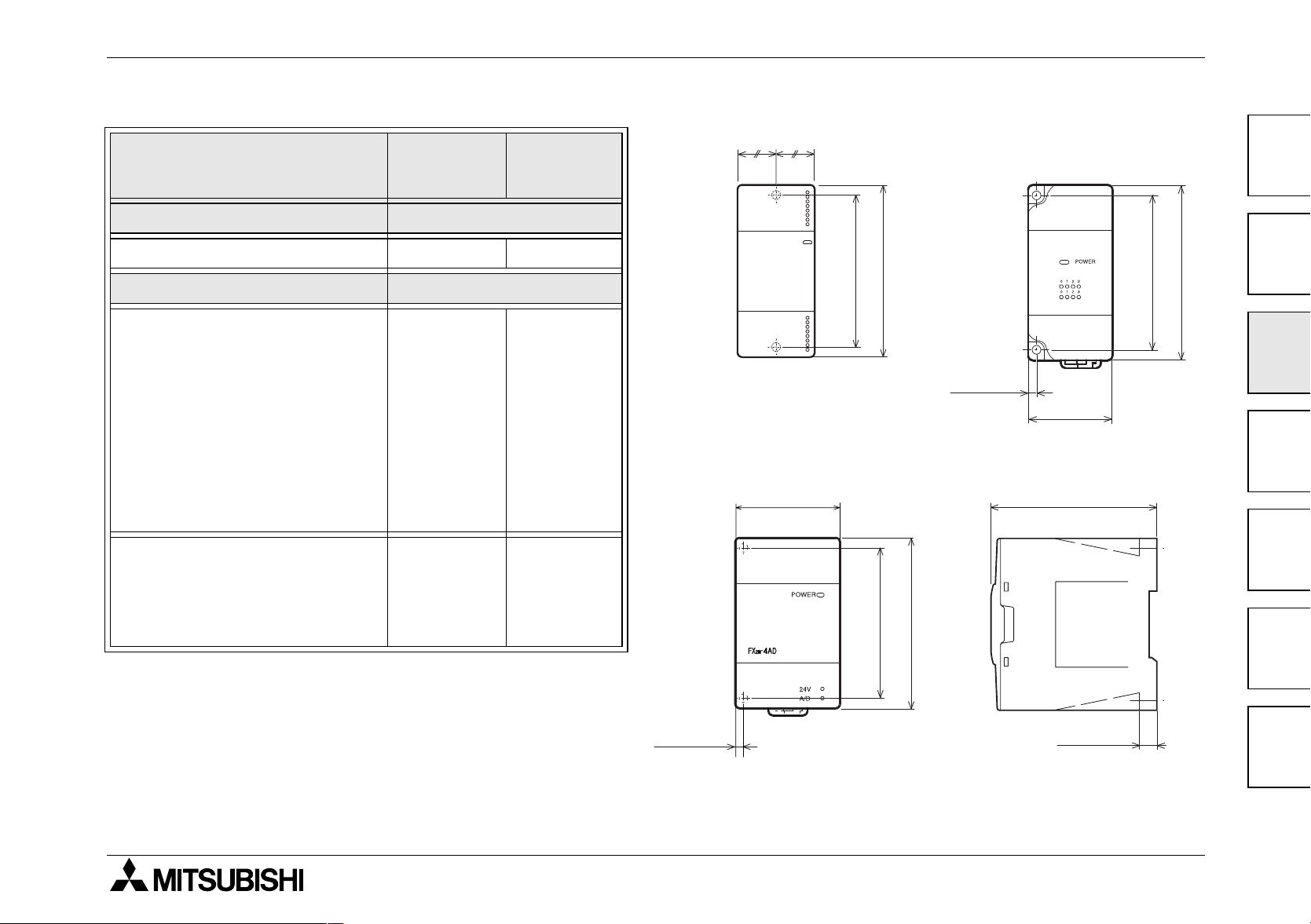
FX1N Series Programmable Controllers Installation Notes 3.
Table 3.3 :Hole positions
FX
FX
FX
FX
FX
FX
FX
FX
FX
FX
FX
FX
FX
UNIT
2N
-16E
✩
0N
-8E✩,
2N
-8E✩,
0N
-3A, FX2N-2AD,
2N
-2DA, FX2N-32CCL,
2N
-16LNK-M,
2N
-64CL-M,
0N
-232ADP,
0N
-485ADP
2N
-4DA, FX2N-4AD
2N
-4AD-PT, FX2N-5A,
2N
-4AD-TC, FX2N-2LC,
2N
-32ASI-M
= 4.5mm (0.17")
∅
mm inches
± 0.2 ± 0.01
C = W/2
20 0.79
D = W
43 1.70
55 2.17
C
FX2N-16EX
D
1
0
IN
1
2
3
4
5
6
7
POWER
FX0N-8ER
2
IN
OUT
80(3.15")
0
IN
1
2
3
4
5
6
7
90(3.55")
80(3.15")
90(3.55")
3
4(0.16")
D
4
87(3.43")
5
80(3.15")
90(3.55")
6
4(0.16")
9(0.36")
7
3-11

FX1N Series Programmable Controllers Installation Notes 3.
Table 3.3 :Hole positions
mm inches
UNIT
± 0.2 ± 0.01
E = W-8mm (0.32")
2N
FX
FX
FX
-8AD 67 2.64
F = W-24.5mm (0.97")
2NC
-232ADP,
65.5 2.58
2NC
-485ADP
= 4.5mm (0.17")
∅
E
W
90(3.55")
98(3.86")
75(2.96")
10
F
W
19.1(0.76")
16.1(0.64")
(0.40")
7(0.28")
74(2.92")
3-12

FX1N Series Programmable Controllers Installation Notes 3.
Table 3.3 :Hole positions
FX
FX
mm inches
UNIT
± 0.2 ± 0.01
G = W-10mm (0.40")
0N
-16E
✩
2N
-16CCL-M 75 2.96
= 4.5mm (0.17")
∅
FX
0N-
16EX-ES
POWER
IN01 234567
01234567
60 2.37
80(3.15")
90(3.55")
W
G
80(3.15")
90(3.55")
1
2
3
87(3.43")
4
5
G
W
9(0.36")
6
7
3-13
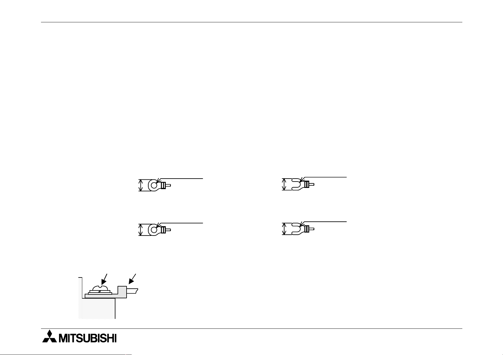
FX1N Series Programmable Controllers Installation Notes 3.
3.7 Termination at Screw Terminals
Terminal screws should be tightened to between 0.5 to 0.8 Nm. Terminal screws must be
secured to prevent a loose connection thus avoiding a malfunction.
The terminal screws for the FX
0N
screws for the FX
-32NT-DP and Terminal Blocks are M3.5. The crimp style terminal (see
Figure 3.3, 3.4, 3.6 and 3.7) is suitable for use with these screws and should be fitted to the
cable for wiring.
When installing 1 or 2 crimp terminals to a terminal, see explanation Figure 3.5 and 3.8.
However, 3 crimp terminals or more should not be installed to a single terminal.
1) Handle the crimp terminal of the following size when 1 wire is used per terminal. Refer to
Figure 3.5 for installation instructions.
Figure 3.3:Crimp Terminal for M3.5 Screws
3.7 (0.15")
6.8 mm (0.27" )
or less
φ
1N
, FX0N, FX2N Series PLCs are M3.0. However, the terminal
3.7 (0.15")
φ
6.8 mm (0.27")
or less
Figure 3.4:Crimp Terminal for M3 Screws
3.2 (0.13")
6.2 mm (0.24" )
or less
φ
6.2 mm (0.24")
or less
Figure 3.5:Installing 1 wire Per a Terminal
Terminal
screw
Terminal
Crimp
terminal
3.2 (0.13")
φ
3-14
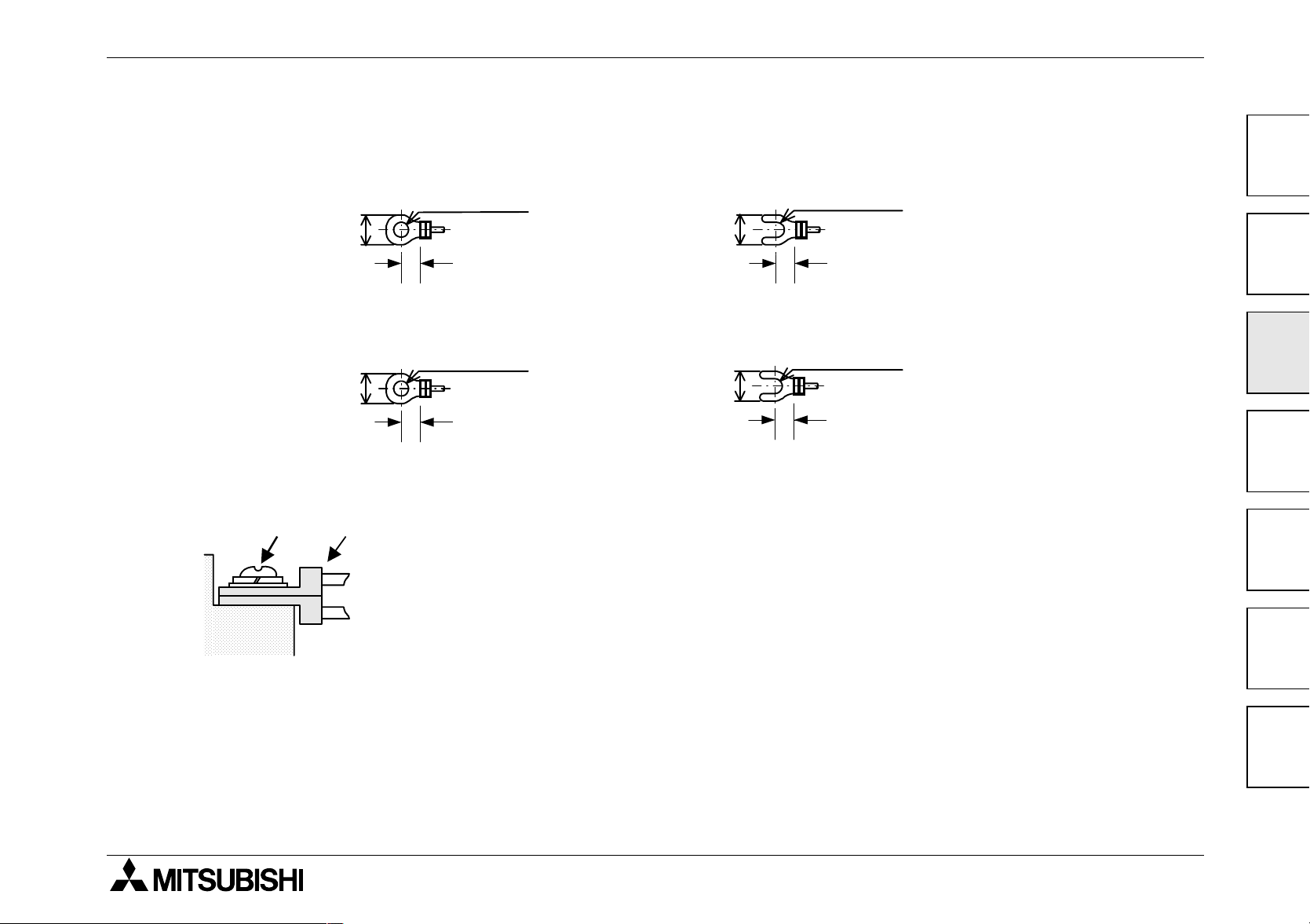
FX1N Series Programmable Controllers Installation Notes 3.
e
2) Handle the crimp terminal of the following size when 2 wires are used per terminal. Refer to
Figure 3.8 for installation instructions.
Figure 3.6:Crimp Terminal for M3.5 Screws
φ
6.8 mm (0.27" )
or less
3.7 (0.15")
6.8 mm (0.27")
or less
6.0 mm or more 6.0 mm or mor
Figure 3.7:Crimp Terminal for M3 Screws
3.2 (0.13")
6.2 mm (0.24" )
or less
φ
6.2 mm (0.24")
or less
6.3 mm or more
Figure 3.8:Installing 2 Wires Per a Terminal
Terminal
screw
Crimp
terminal
φ
3.7 (0.15")
3.2 (0.13")
φ
6.3 mm or more
1
2
3
4
5
Terminal
6
7
3-15

FX1N Series Programmable Controllers Installation Notes 3.
3.8 Installing Optional Units
3.8.1 Expansion Boards
1N
The following is a generic explanation of how to install an expansion board on to the FX
For greater detail, specifications and wiring examples for each optional unit, please see the
relevant product manuals.
MODEL USE WITH FX1N-5DM USE WITH FX1N-EEPROM-8L
1N
FX
FX
-232-BD
1N
-422-BD
✔
✔
PLC.
FX1N-485-BD
FX1N-CNV-BD
FX1N-8AV-BD
FX1N-4EX-BD
FX1N-2EYT-BD
FX1N-2AD-BD
FX1N-1DA-BD
✔
Possible for program upload and
✔
download while the PLC is in the
STOP mode.
✔
✔
✔
✘✘
✘✘
3-16

FX1N Series Programmable Controllers Installation Notes 3.
Always make sure the power is turned off, before installing a special function board. Only one
board can be used at any one time, do not try to stack multiple boards.
D)
A)
C)
D)'
B)
Note
C)
E)
A) Special function or optional equipment board.
B) Optional equipment connector port.
C) M3 screw to secure board.
D) Top cover for board.
E) M3 screw to secure top cover.
Note: Do not remove this screw.
• Remove base unit top cover.
• Plug board A) into connector B).
• Fix board to base unit using screws C).
• Attach top cover for board D) removing section D)’ to expose
connector etc. (if applicable)
• Secure top cover with M3 screw E).
1
2
3
4
5
3-17
6
7

FX1N Series Programmable Controllers Installation Notes 3.
B)
A)
C)
3.8.2 FX1N-5DM Display Module
Always make sure the power is turned off, before installing the 5DM.
A) Top cover for DM
B) Optional equipment connector port.
C) M3 screw to secure top cover.
• Remove the base unit top cover.
• Attach the top cover for DM A), and
secure with screw C) (if 5DM is to be
permanently mounted)
• Plug in the 5DM at connector B)
For further information please refer to the FX
1N
-5DM users manual.
3-18
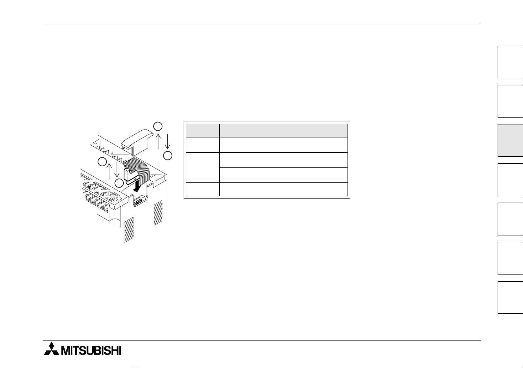
FX1N Series Programmable Controllers Installation Notes 3.
3.8.3 Extension I/O module and Special Function module
Install/remove extension module as shown in the figure below.
Caution
Cut off all phases of power source before installing/removing the extension module.
1
'
2
2
3
Ref. Description
1 Remove the extension bus cover.
2: Install extension cable.
2 or 2'
2': Remove extension cable.
3 Install the extension bus cover.
1
2
3
4
5
3-19
6
7

FX1N Series Programmable Controllers Installation Notes 3.
MEMO
3-20

FX1N Series Programmable Controllers
4. Power Supply
Power Supply 4.
4.1 Wiring Techniques
Wiring for FX1N products has been designed to be safe and easy. If the user is concerned
about the correct installation of these products or associated products, please contact a
professional electrician who is trained to the local and national standards applicable to the
installation site.
4.2 Wiring Cautions
• Do not run input signals in the same multicore cable as output signals or allow them to
share the same wire.
• Do not lay I/O signal cables next to power cables or allow them to share the same trunking
duct. Low voltage cables should be reliably separated or insulated with regard to high
voltage cabling.
1
2
3
4
5
• Where I/O signal lines are used over an extended distance consideration for voltage drop
and noise interference should be made.
4-1
6
7

FX1N Series Programmable Controllers Power Supply 4.
4.3 Power Supply
• When wiring an AC supply, the “Live” cable should be connected to the “L” terminal and the
“Neutral” cable should be connected to the “N” terminal. Do NOT connect the “Live” wire to
the “N” terminal, otherwise, the user may receive a dangerous shock upon powerup.
• When wiring a DC supply the “Live” cable should be connected to the “+” terminal and the
“Neutral” cable should be connected to the “-” terminal. Do NOT connect the “Live” wire to
the “-” terminal, otherwise, the user may receive a dangerous shock upon powerup.
4-2

FX1N Series Programmable Controllers Power Supply 4.
4.4 Power Requirements
Table 4.1 :AC Power Supply Units
FX1N-14M FX1N-24M FX1N-40M FX1N-60M
Power supply 100 - 240V AC +10%, -15%, 50-60Hz
Max. allowable momentary power
failure period
Fuse (size) rating 250V 1A 250V 3.15A (3A)
In-rush current
Power consumption 29W
24V DC Service Supply 400 mA
10ms; if less than 10ms, the PLC will continue operation.
If 10ms or more, the PLC will shut down
100V AC - Max. 30A for 5ms
200V AC - Max. 50A for 5ms
*1
30W
*1
32W
*1
35W
*1 Includes the input current (5 or 7mA per point).
Table 4.2 :DC Power Supply Units
FX1N-14M FX1N-24M FX1N-40M FX1N-60M
Power supply 24V DC +20% ~ 12V DC -15% (28.8 ~ 10.2V DC)
1
2
3
*1
4
5
Max. allowable momentary power
failure period
Fuse (size) rating 125 V 3.15A
In-rush current
Power consumption
*1
5 ms; If less than 5 ms, the PLC will continue operation.
If 5 ms or more, the PLC will shut down
24V DC - Max. 25A for 1ms
12V DC - Max. 22A for 0.3ms
13W 15W 18W 20W
*1 Includes the input current (5 or 7mA per point).
6
7
4-3

FX1N Series Programmable Controllers Power Supply 4.
4.5 Example Wiring
4.5.1 AC Power supply
➓
100-240V
AC
50/60 Hz
➊
➎
➋
➋
24V DC
11
➌➍
MC
12
➐
*1 *1
L 24VN 0V
L 24VN 0V
12
24+ 24-
➑
➏
➏
AC/DC
Converter
➒
24+ 24-
Extension
Block
Powered extention
unit
*1 It is recommended to use the same power source to power the main unit, powered
extension units and special function blocks/units. If two sources are required, follow the
below guidelines:
- Supply power to the powered extension units and special function blocks/units before
or at the same time the main unit is powered.
- The power supplies may be cut the same time after ensuring system safety.
Special
Function
Block/Unit
4-4

FX1N Series Programmable Controllers Power Supply 4.
Grounding resistor 100Ω or less
AC Power supply 100 - 240V AC,
➊
+10% -15%, 50 - 60 Hz
➐
➑
Fuse
1
Circuit protector or Fuse
➋
Emergency stop
➌
Power supply switch DC Power supply 24V DC
➍
Power ON pilot indicator Service Power Supply, 24V DC 400mA
➎
Power supply for loads
➏
Main unit
➒
Breaker
➓
11
12
2
3
4
5
6
4-5
7

FX1N Series Programmable Controllers Power Supply 4.
4.5.2 24V DC Power supply
➓
24V DC
➊
➋
➋
➋
➎
➌➍
MC
*1 *1
➑
➒
➏
➏
*1 It is recommended to use the same power source to power the main unit, powered
extension units and special function blocks/units. If two sources are required, follow the
below guidelines:
- Supply power to the powered extension units and special function blocks/units before
DC/DC
Converter
11
➐
24V 0V
24+ 24-
S/S
Extension
Block
S/S 0V
12
Powered extension unit
(Only connect DC power
supply type for FX
Series)
0N
24+ 24-
Special
Function
Block/Unit
or at the same time the main unit is powered.
- The power supplies may be cut the same time after ensuring system safety.
4-6
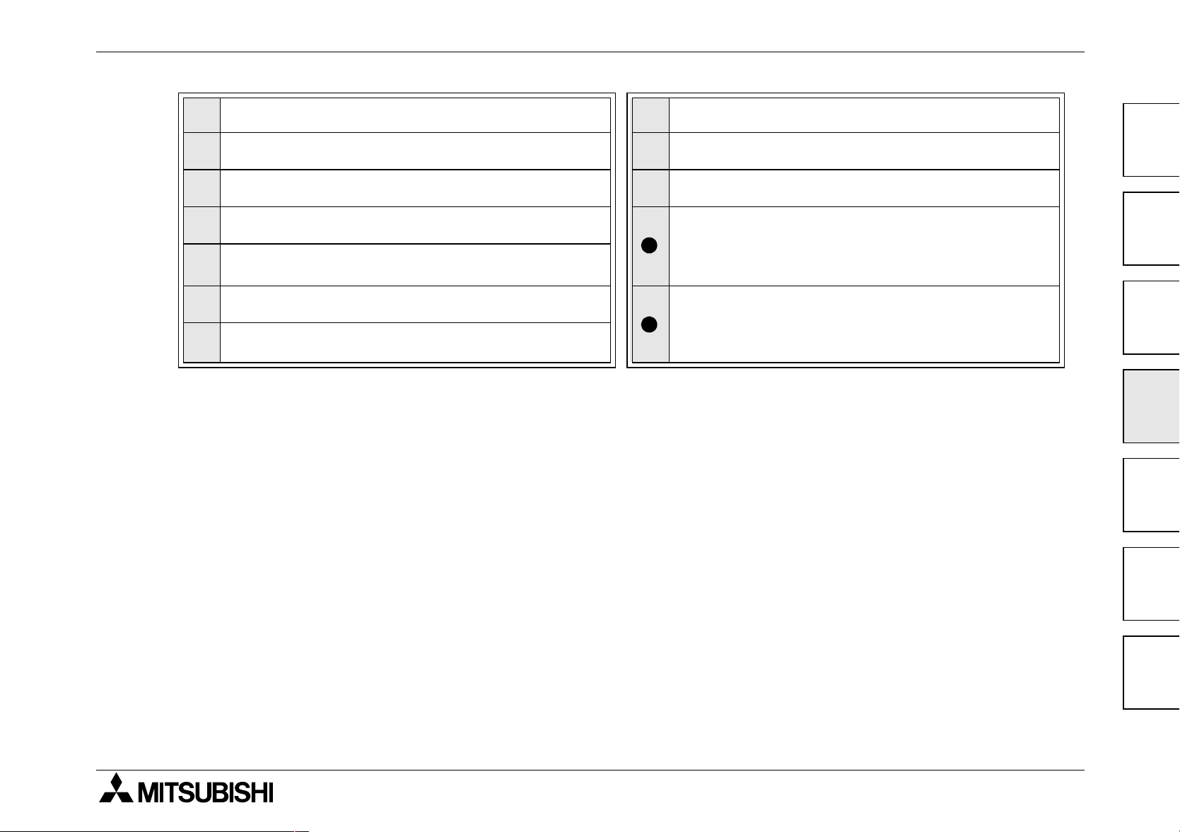
FX1N Series Programmable Controllers Power Supply 4.
DC Power supply, 24V DC, +10% -15%
➊
Circuit protector or Fuse
➋
Emergency stop
➌
Power supply switch
➍
Power ON pilot indicator
➎
Power supply for loads
➏
Grounding resistor 100Ω or less
➐
Fuse
➑
Main unit
➒
Breaker
➓
Power supply for the input circuitry of the
main unit and extension blocks that are
11
connected.
Powered extension unit of 24V DC supply
0N
type for FX
12
(FX
0N
-40ER-DS or FX0N-40ET-DSS)
Series
1
2
3
4
5
4-7
6
7

FX1N Series Programmable Controllers Power Supply 4.
4.5.3 12V DC Power Supply
➓
12V DC
➊
➋
➎
➌➍
MC
➑
➏
DC Power supply, 24V DC, +10% -15%
➊
Circuit protector or Fuse
➋
➏
DC/DC
Converter
➒
11
➐
24V 0V
24+ 24-
S/S
12 12
Extension
Input
Block
Fuse
➑
Main unit
➒
Extension
Output
Block
Emergency stop
➌
Power supply switch
➍
Power ON pilot indicator
➎
Power supply for loads
➏
Grounding resistor 100Ω or less
➐
Breaker
➓
Power Supply for the input circuitry of the
main unit and extension blocks that are
11
connected.
When using a 12V DC power supply,
extension blocks occupying up to 32
12
I/O points are connected.
4-8

FX1N Series Programmable Controllers Power Supply 4.
4.6 Service Power supply
An AC powered FX1N can supply a service current of 24V DC at 400mA when used on its own
and, when used with extension or special function blocks.
A DC powered FX
Additional extension blocks can be powered from the main units power supply.
1N
does not have the capacity to supply a service current. However
4.7 Earthing / Grounding
Use a cable at least 0.2mm2 (AWG24) to ground equipment. Ground resistance must be
less than 100Ω. Note that the ground cable must not be connected to the same ground as
the power circuits.
1
2
3
4
5
4-9
6
7

FX1N Series Programmable Controllers Power Supply 4.
MEMO
4-10
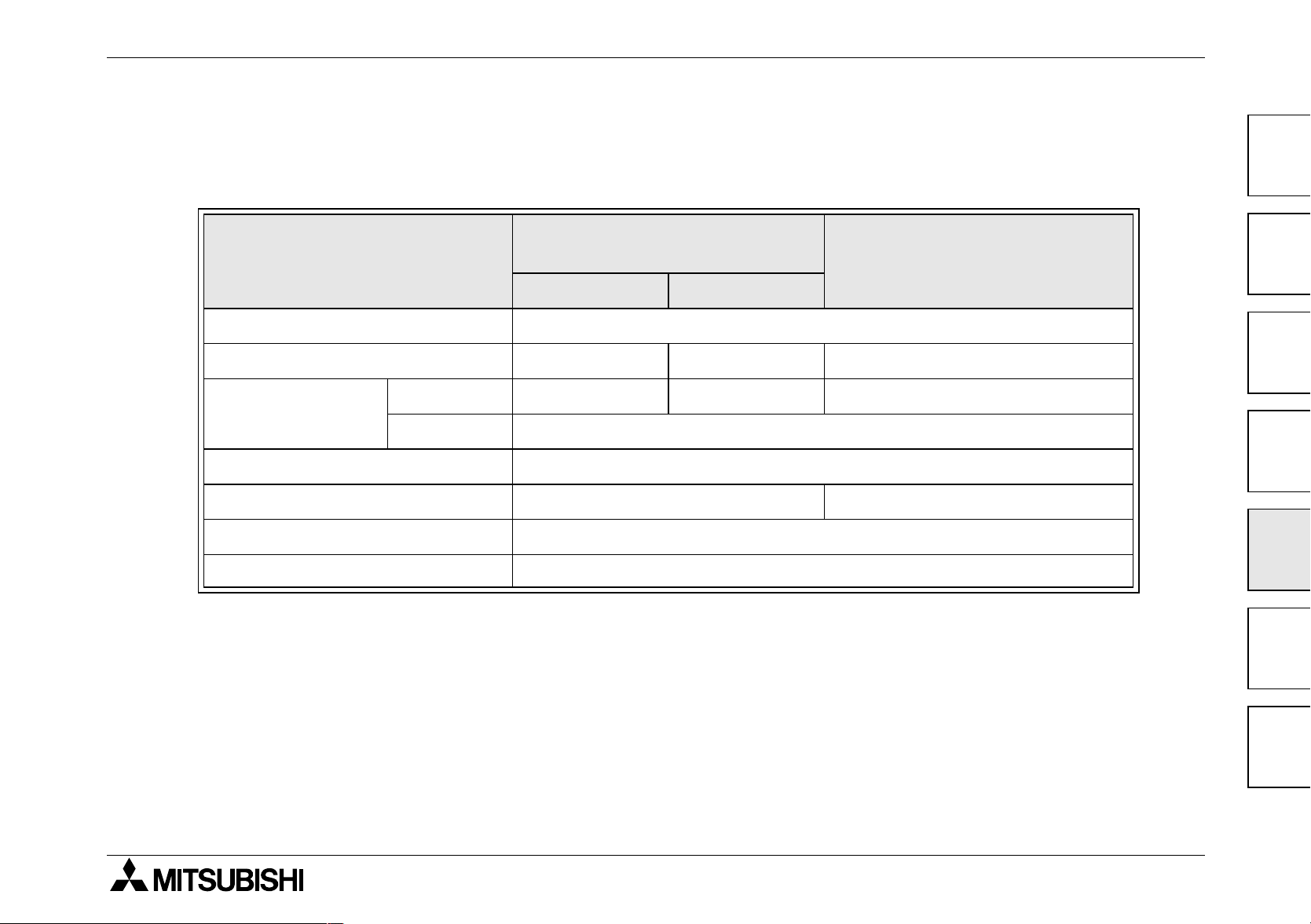
FX1N Series Programmable Controllers
5. Inputs
5.1 24V DC input Specifications
FX1N main unit,
extension block
FX0N, FX2N Extension block
Inputs 5.
1
2
X0 → X7 X10 →
Input voltage 24V DC ±10%
Input current 24V DC, 7mA 24V DC, 5mA 24V DC, 5mA
Input switching
current
Response time 10ms
Variable response time X000-X007 0-15ms ---
Circuit isolation Photocoupler
Operation indication LED is lit
OFF → ON >4.5mA >3.5mA >3.5mA
ON → OFF <1.5mA
∞
3
4
5
6
5-1
7
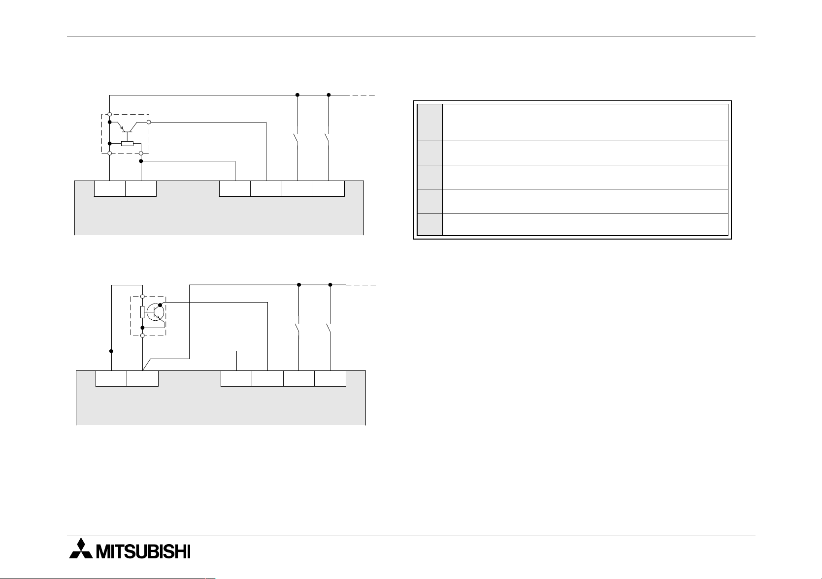
FX1N Series Programmable Controllers Inputs 5.
5.1.1 Typical Wiring
PNP
➋
24V 0V S/S X0 X1 X2
➊
NPN
24V 0V S/S X0 X1 X2
➌
➊
➍
➎
➍
➎
AC model - Service supply
➊
DC model - Input circuit power supply
PNP Sensor
➋
NPN Sensor
➌
Input Device Contact
➍
Main unit
➎
Note
: The input circuit power supply provides a clean
+24VDC supply for the inputs. Hence use an external
+24VDC power supply at your own risk.
The input circuit power supply cannot provide a
service supply to special function blocks (SFB). Use
an external supply to power the SFBs.
When using an AC powered unit, an external 24V DC
supply can be used.
5-2

FX1N Series Programmable Controllers Inputs 5.
24V
X
24V DC
0V
S/S
Sink
(+ve S/S)
5.1.2 Input Circuit Connection
FX
FX
Main and FX0N/FX2N Extension Units
1N
24V
24V DC
X
S/S
0V
and FX0N Extension blocks
2N
Source
(-ve S/S)
Source
Sink
1
2
3
4
5
24V DC
±10%
X
S/S
24V DC
±10%
X
6
S/S
7
5-3

FX1N Series Programmable Controllers Inputs 5.
5.1.3 Diodes and Inputs Connected in Series
Vdrop across the diode Max. 4V
No more than 2 LEDs should be connected in series.
FX
24V
X
S/S
0V
1N
5.1.4 Resistors and Inputs Connected in Parallel
1N
Parallel resistance Rp: FX
= 15kΩ. If resistance Rp is less than the stated value, then add
Rb. See equation 1 for Rb calculation.
1N
Alternatively; Current leakage: FX
= 1.5mA. If the current leakage is greater than the stated
value, then add Rb. See equation 2 for Rb calculation.
Parallel LED
24V
Rp
Eqn 1 :
Rb
≤
4
15 -
Rp
Rp
FX0N, FX
Extension
block
X
S/S
2N
Eqn 2 :
Rb
6
≤
I
- 1.5
Rb
X
S/S
0V
5-4
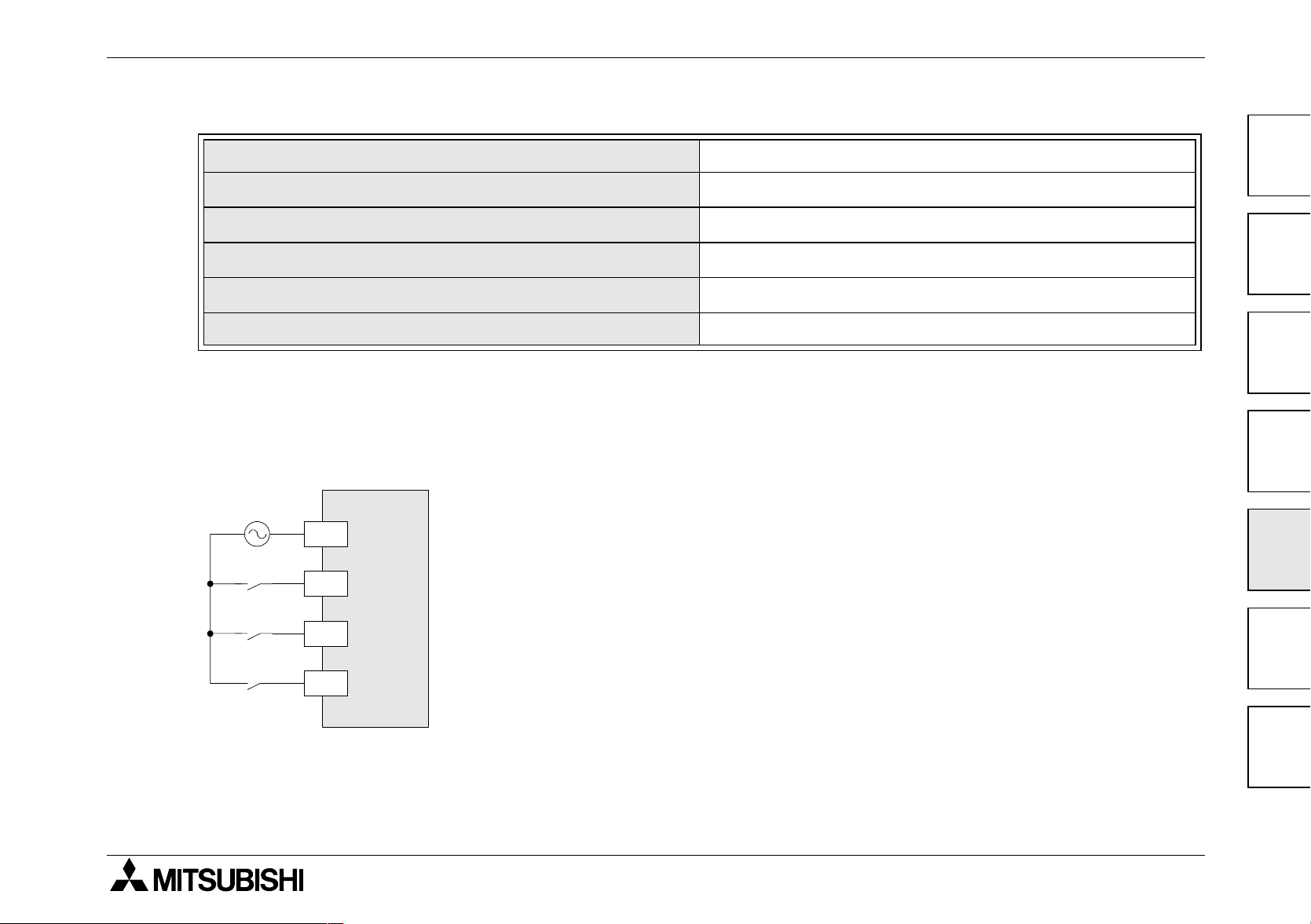
FX1N Series Programmable Controllers Inputs 5.
5.2 AC110V Input Extension Block
Input voltage
Input impedance
Input current
OFF → ON/ON → OFF; input switching current
Response time
Circuit isolation / Operation indication
5.2.1 Input Circuit Connection
FX
FX
85-132 V AC
50/60 Hz
-8EX-UA1/UL
0N
-8EX-UA1/UL
2N
COM1
X0
85-132V AC 50-60Hz
21kΩ/50HZ 18kΩ/60Hz
4.7mA 100V AC/50Hz 6.2mA 110V AC/60Hz
80V 3.8mA/30V 1.7mA
25ms
Photocoupler/LED is lit
1
2
3
4
5
X1
X2
6
7
5-5

FX1N Series Programmable Controllers Inputs 5.
5.2.2 Programming Caution
When using 110V AC units, high speed counter and interrupt routines are not suitable for use
due to the long 'ON/OFF' times. The following instructions are also not suitable.
FNC 52 MTR
FNC 56 SPD
FNC 72 DSW
5-6

FX1N Series Programmable Controllers
6. Outputs
Outputs 6.
6.1 Output Specifications
Description Relay Output Transistor Output
240V AC,
Switched voltages (resistive load)
Rated current / N points (resistive
load)
Max. Inductive load 80VA, 120/240V AC 12W/24V DC
When supply voltage < 5V DC
Minimum load
allow at least 2mA flow
OFF → ON 10ms
Response time
(approx.)
ON → OFF 10ms
Circuit isolation By Relay By Photo Coupler
Open circuit current leakage - 0.1mA/30V DC
≤
30V DC
≤
2A/1 point,
8A/COM
5-30V DC
0.5A/1 point,
0.8A/COM
-
< 0.2ms;
< 5µs (Y000,Y001 only)
< 0.2ms (I > 0.2A);
<5µs (Y000,Y001 only)
1
2
3
4
5
Operation indication LED is lit when coil is energized
Internal device None
Output protection
Outside device
Rated value according to the load.
(Fuse)
6
7
6-1

FX1N Series Programmable Controllers Outputs 6.
6.2 Relay Output Example
Typical Relay
➎
COM0
➋
➒
Y000 COM1 Y001 COM2 Y002 Y003 Y004 Y005
COM3
MC2 MC1
➋
➌
➐
➑
➎
➍
➊
➐
MC2MC1
➏
➓
)
Do not use this terminal
➊
Fuse
➋
Reverse-current protection diode (See section 6.4)
➌
External Mechanical Interlock (See section 6.4)
➍
Emergency Stop
➎
Surge absorber (0.1µF capacitor + 100-120Ω resistor)
➏
(See section 6.4)
Inductive load
➐
Incandescent Lamp
➑
DC Power Supply
➒
AC Power Supply
➓
6-2

FX1N Series Programmable Controllers Outputs 6.
6.2.1 Reliability Tests
The test results in the table below were gathered from a 1 sec ON/OFF test cycle. Please note
that the over current induced by in-rush greatly reduces the relay contact’s service life. The
rated life for an inductive AC load such as a conductor or solenoid valve is 500,000 operations
at 20VA.
1
20VA 35VA 80VA
Load capacity
0.2A/100VAC
0.1A/200VAC
Life of contact (cycles) 3,000,000 1,000,000 200,000
Example load (Mitsubishi contactor) S-K10 ~ S-K95 S-K100 ~ S-K150 S-K180,S-K400
0.35A/100V AC
0.17A/240V AC
0.8A/100V AC
0.4A/240V AC
2
3
4
5
6
6-3
7
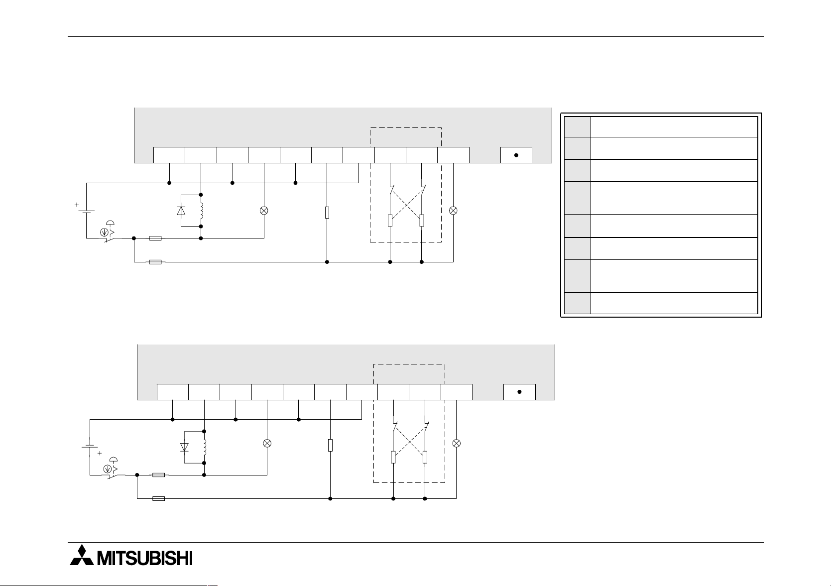
FX1N Series Programmable Controllers Outputs 6.
6.3 Transistor Output Example
6.3.1 Transistor Output Writing Diagram (Source Type)
Do not use this terminal
➊
Emergency Stop
➋
Fuse
➌
External Mechanical
➍
Interlock (See Section 6.4)
DC Power Supply
➎
Incandescent Lamp
➏
Reverse-current protection
➐
diode
Inductive load
➑
➎
➋
+V0 Y000 Y001 Y003+V1 Y002 Y004
+V2 +V3 Y005
MC1 MC2
➑➐ ➏
➍
MC2 MC1
➌
➌
➊
➏
6.3.2 Japanese Model Transistor Output (SInk Type)
COM0
Y000 Y001 Y003
COM1 Y002
COM2 COM3
Y004
MC1 MC2
Y005
➎
➑➐
➍
MC2 MC1
➋
➌
➌
➊
➏➏
6-4

FX1N Series Programmable Controllers Outputs 6.
6.3.3 Response Times
OFF times increase as the load current decreases.
For improved response times use a ‘dummy’ resistor, see the figure below. If a response time
of 0.5 ms or better is required when using ‘light loads’ use a ‘dummy’ resistor and ensure the
signal line has a current greater than 60mA/24V DC
1
Dummy
Load
+V
60 to 200mA
Y
Dummy load Load
5 to 24V
Y000 and Y001 are high speed response
outputs with the following characteristics:
10 - 100mA at 5 - 24V DC, 100kHz maximum
output signal.
If a high speed response is required, a current
of 10 - 100mA must be used.
2
3
4
5
6
6-5
7

FX1N Series Programmable Controllers Outputs 6.
DC (+) DC (-)
PLC output
Inductive load
Reverse-current
protection diode
DC (+) DC (-)
PLC
output
Inductive load
Reverse-current
protection diode
6.4 Applying Safe Loads
Caution for DC Loads
1) Relay output case
This PLC does not have any internal protection
circuitry on the relay outputs. For switching direct
current on inductive loads, a reverse-current
protection diode should be installed in parallel with
the load. The relay contact life decreases
significantly if this is not done.
The reverse-current protection diode needs to
satisfy the following specifications.
- The diode is rated for maximum reverse voltage of 5 to 10+ times the load voltage.
- The forward current is more than the load current.
2)Transistor output case
Transistor outputs use internal zener diode (50V)
as protection circuitry. When driving the inductive
load with transistor output, a reverse-current
protection diode can be installed in parallel with the
load if necessary.
The reverse-current protection diode needs to
satisfy the following specifications.
- The diode is rated for maximum reverse voltage of 5 to 10+ times the load voltage.
- The forward current is more than the load current.
6-6

FX1N Series Programmable Controllers Outputs 6.
OK!!
PLC output
Load
PLC output
Load
NG!!
PLC output
Load
PLC output
Load
Caution for AC Loads
1) Relay output case
This PLC does not have any internal protection
circuitry on the relay outputs. For switching AC on
inductive loads, a surge absorber (0.1µF + “100
to 120Ω”) should be installed in parallel with the
load. The relay contact life decreases significantly
if this is not done.
Besides protecting the internal circuity of the
PLC, a surge absorber decreases the noise
emissions to the load.
Component Side of Loads
The output contact of the PLC should be connected to
components consistently as indicated in the figure
Note: If using another output type, please replace
symbol with appropriate symbol.
100V AC
PLC output
1
100V AC
Inductive load
2
Surge absorber
3
4
5
6
7
6-7

FX1N Series Programmable Controllers Outputs 6.
PLC output
MC1
Forward
operation
MC2 LSF
MC1MC2 LSF
PLC output
Reverse
operation
Mechanical
interlock
Mechanical Interlock
Ensure all loads are applied to the same side of
each PLC output, see previous figures. Loads
which should NEVER simultaneously operate
(e.g. direction control of a motor), because of a
critical safety situation, should not rely on the
PLC’s sequencing alone. Mechanical interlocks
MUST be fitted to all critical safety circuits. (See
proceeding figure.)
Note: If using another output type, please replace
symbol with appropriate symbol.
6-8
 Loading...