

Page 1
PROGRAMMING MANUAL
THE FX SERIES OF PROGR AMM ABLE CONTROLLER
(FX0, F X0S, F X0N, F X , F X
2C, FX2N, FX2NC
)
Page 2

Page 3

FX Series Programmable Controllers
g
g
g
y
g
y
j
FX Series Programmable Controllers
Programming Manual
Manual number : JY992D48301
Manual revision : J
Date : November 1999
Foreword
• This manual contains text, dia
the correct pro
• Before attemptin
understood.
• If in doubt at an
electrical en
which appl
• If in doubt about the operation or use of the PLC please consult the nearest
Mitsubishi Electric distributor.
• This manual is sub
ramming and operation of the PLC.
to install or use the PLC this manual should be read and
stage of the installation of the PLC always consult a professional
ineer who is qualified and trained to the local and national standards
to the installation site.
ect to change without notice.
rams and explanations which will guide the reader in
i
Page 4

FX Series Programmable Controllers
ii
Page 5

y
y
y
g
g
y
y
y
g
y
y
y
y
y
y
g y
y
y y
y
y
FX Series Programmable Controllers
FAX BACK - Combined Programming Manual (J)
Mitsubishi has a worl d wide rep utation fo r its eff orts i n continual l
the frontiers of industrial automation. What is sometimes overlooked b
and attention to detail that is taken with the documentation. However,to continue this process
of improvement, the comments of the Mitsubishi users are alwa
been desi
ward to hearin
Please tick the box of
Fax numbers: Your name....................................................
Mitsubishi Electric.... .....................................................................
America (01) 847-478-2253 Your compan
Australia (02) 638-7072 .....................................................................
German
South Africa (0111) 444-8304 .................... ................................. ................
United Kin
What condition did the manual arrive in?
Will
ned for you,the reader ,t o fill in your comments and fax them back to us. W e look fo r-
from you.
our choice;
(0 21 02) 4 86-1 12 Your location: ...............................................
dom (01707) 278-695
Good
ou be using a folder to store the manual?
developing and pushing back
the user is the care
s welcomed. This page has
..............................................
Minor damage
Yes
Unusable
No
What do
Are the explanations understandable?
Which explanation was most difficult to understand:..................................................................
....................................................................................................................................................
Are there an
If so,which:..................................................................................................................................
What do
If there one thin
....................................................................................................................................................
....................................................................................................................................................
Could
ble please identif
....................................................................................................................................................
....................................................................................................................................................
....................................................................................................................................................
....................................................................................................................................................
Do
....................................................................................................................................................
....................................................................................................................................................
....................................................................................................................................................
....................................................................................................................................................
ou think to the manual presentation?
Yes
diagrams which are not clear?
ou think to the manual layout?
ou would like to see improved,what is it?......................................................
ou find the information you required easily using the index and/or the contents,if possi-
our experience: ...........................................................................................
ou have any comments in general about the Mitsubishi manuals?.....................................
Good
Tid
Not too bad
Yes
Not too bad
Un-friendl
Unusable
No
Un-helpful
Thank
and this manual easy to use.
ou for taking the time to fill out this questionnaire. W e hope you found both the
product
iii
Page 6

FX Series Programmable Controllers
iv
Page 7
FX Series Programmable Controllers
y
y
g
g
y
j
g
y
y
y
g
y
y
y
g
g
g
y
g
Guidelines for the Safety of the User and Protection of the Programmable
Controller (PLC)
This manual provides information for the use of the FX family of PLC’s. The manual has been
written to be used b
persons is as follows;
trained and competent personnel. The definition of such a person or
a) An
engineer who is responsible for the planning, design and construction of automatic
equipment usin
the product associated with this manual should b e of a competent
nature, trained and qua lified to the local an d national standa rds required to fulfill tha t
role. These en
ineers should be fully aware of all aspects of safety with regards to
automated equipment.
b) An
commissioning or service engineer must be of a competent nature, trained and
qualified to the local and national stand ards required to fulfill that
ob. These engineers
should also be trained in the use and maintenance of the completed product. This
includes bein
completely familiar with all associat ed documentation for the said
product. All maintenance should be carried out in acc ordance with established safet
practices.
c) All operators of the completed equipment should be trained to use that product in a safe
and coordinated manner in compliance to established safet
practices. The operators
should also be familiar with documentation which is connected with the actual operation
of the completed equipment.
Note :
the term ‘completed equipment’ refers to a third part
constructed device which
contains or uses the product associated with this manual.
Note’s on the Symbols used in this Manual
At various times throu
information which are intended to ensure the users personal safet
equipment. Whenever an
be read and understood. Each of the s
its meanin
.
h out this manual certain symbols will be used to highlight points of
and protect the integrity of
of the following symbols are encountered its associated note must
mbols used will now be listed with a brief descript ion of
Hardware Warnings
1) Indicates t hat the identified dan
2) Indicates that the identified dan
damage.
3) Indicates a point of further interest or further explanation.
Software Warning s
4) Indicates special care must be taken when usin
5) Indicates a special point which the user of the associate software element should
be aware of.
6) Indicates a point of interest or further explanation.
WILL
er
er could
cause physical and property damage.
POSSIBLY
cause physical and propert
this element of software.
v
Page 8

FX Series Programmable Controllers
vi
Page 9

g
g
g
g
g
g
g
g
g
FX Series Programmable Controllers
Contents
1. Introduction............................................................................................1-1
1.1 Overview..............................................................................................................1-1
1.2 What is a Pro
rammable Controller? ..................................................................1-2
1.3 What do You Need to Pro
1.4 CPU version numbers .........................................................................................1-3
1.4.1 FX0N CPU versions...................................................................................................1-3
1.4.2 FX and FX
2C
1.5 Special considerations for programming equipment ....... .. ... ............... .. ... ...........1-4
1.5.1 FX CPU version 3.07 or later and FX2C ................................................................... 1-4
1.5.2 FX
2N
(C) CPU all versions ........................................................................................1-5
2. Basic Program Instructions ...................................................................2-1
2.1 What is a Program?.... .. ... .. .. .. ... .. .. .... ... .. .. .. .. ... .. .. .. .. ..... .. .. .. ... .. .. .. ... .. .. .... ... .. .. .. .. ...2-1
2.2 Outline of Basic Devices Used in Pro
2.3 How to Read Ladder Lo
2.4 Load, Load Inverse ..............................................................................................2-3
2.5 Out.......................................................................................................................2 -4
2.5.1 Timer and Counter Variations ...................................................................................2-4
2.5.2 Double Coil Desi
2.6 And, And Inverse.................................................................................................2-6
2.7 Or, Or Inverse......................................................................................................2-7
2.8 Load Pulse, Load Trailin
2.9 And Pulse, And Trailin
2.10 Or Pulse, Or Trailin
2.11 Or Block.............................................................................................................2-11
2.12 And Block ..........................................................................................................2-12
2.13 MPS, MRD and MPP......................................... .. .. .. ..........................................2-13
2.14 Master Control and Reset................................................... ...............................2-15
2.15 Set and Reset................. ................................. ................................. .................2-17
2.16 Timer, Counter (Out & Reset)................................... .. .. .. .. .. ...............................2-18
2.16.1 Basic Timers, Retentive Timers And Counters........................................................2-18
2.16.2 Normal 32 bit Counters ...........................................................................................2-19
2.16.3 Hi
2.17 Leading and Trailing Pulse................................................................................2-20
2.18 Inverse...............................................................................................................2-21
2.19 No Operatio n . .. .. ............................... ... .. ............................... .. .. .........................2-22
2.20 End ....... .. ............................................... .. .. ............................... .. ... ............... .. .. .2 -23
h Speed Counters ..............................................................................................2-19
ram a PLC? ..............................................................1-2
CPU versions.......................................................................................1-3
ramming..................................................2-1
ic..................................................................................2-2
nation..... ...... ....... ...... ....... ...... ...... ....... ...... ....... ...... ....... ...... ....... ...2-5
Pulse. .. .. ................ .. .. ............... ... .. .............................2-8
Pulse.............................................................................2-9
Pulse................................................................................2-10
i
Page 10

g
g
g
g
g
g
g
g
g
g
y
y
g
g
y
y
g
g
y
FX Series Programmable Controllers
3. STL Programming.................................................................................3-1
3.1 What is STL, SFC And IEC1131 Part 3?.............................................................3-1
3.2 How STL Operates..............................................................................................3-2
3.2.1 Each step is a program .............................................................................................3-2
3.3 How To Start And End An STL Program.............................................................3-3
3.3.1 Embedded STL programs .........................................................................................3-3
3.3.2 Activatin
3.3.3 Terminatin
3.4 Moving Between STL Steps................................................................................3-5
3.4.1 Using SET to drive an STL coil .................................................................................3-5
3.4.2 Usin
3.5 Rules and Techniques For STL programs...........................................................3-7
3.5.1 Basic Notes On The Behavior Of STL programs.......................................................3-7
3.5.2 Sin
3.6 Restrictions Of Some Instructions When Used With STL..................................3-10
3.7 Usin
3.8 Usin
STL To Select The Most Appropriate Program .......................................3-11
STL To Activate Multiple Flows Simultaneously......................................3-12
3.9 General Rules For Successful STL Branchin
3.10 General Precautions When Usin
3.11 Pro
3.11.1 A Simple STL Flow..................................................................................................3-16
3.11.2 A Selective Branch/ First State Mer
ramming Examples ....................................................................................3-16
3.12 Advanced STL Use............................................................................................3-20
new states.................................................................................................3-3
an STL Program....................................................................................3-4
OUT to drive an STL coil.................... ...... ...... ....... ...... ....... ...... ....... ...... ....... ... 3-6
le Signal Step Control ........................................................................................3-9
..................................................3-14
The FX-PCS/AT-EE Software.....................3-15
e Example Program...................................... .3-18
4. Devices in Detail....................................................................................4-1
4.1 Inputs...................................................................................................................4-1
4.2 Outputs ................................................................................................................4-2
4.3 Auxiliar
4.3.1 General Stable State Auxiliary Relays ......................................................................4-3
4.3.2 Batter
4.3.3 Special Dia
4.3.4 Special Sin
4.4 State Relays ........................................................................................................4-6
4.4.1 General Stable State - State Relays .........................................................................4-6
4.4.2 Batter
4.4.3 STL Step Rela
4.4.4 Annunciator Fla
4.5 Pointers .............................................................................................................4-10
4.6 Interru p t Po in te r s ............. ............... .. ... .............................. ... .. ...........................4-11
4.6.1 Input Interrupts ........................................................................................................4-12
4.6.2 Timer Interrupts.......................................................................................................4-12
4.6.3 Disablin
4.6.4 Counter Interrupts ...................................................................................................4-13
4.7 Constant K.........................................................................................................4-14
4.8 Constant H.........................................................................................................4-14
4.9 Timers................................................................................................................4-15
4.9.1 General timer operation...........................................................................................4-16
4.9.2 Selectable Timers.................................. ............................................. ....... ...... ....... .4-16
4.9.3 Retentive Timers .....................................................................................................4-17
4.9.4 Timers Used in Interrupt and ‘CALL’ Subroutines ...................................................4-18
4.9.5 Timer Accurac
4.10 Counters............................................................................................................4-19
4.10.1 General/ Latched 16bit UP Counters ......................................................................4-20
4.10.2 General/ Latched 32bit Bi-directional Counters.......................................................4-21
Relays....................................... ............................... .............................4-3
Backed/ Latched Auxiliary Relays.................................................................4-4
nostic Auxiliary Relays ...................................... ....... ...... ....... ...... ....... ... 4-5
le Operation Pulse Relays.....................................................................4-5
Backed/ Latched State Relays............... ...... ....... ...... ....... ...... ....... ...... ....... ...4-7
s .......................................................................................................4-8
s .....................................................................................................4-9
Individual Interrupts .................................................................................4-13
.......................................................................................................4-18
ii
Page 11

y
y
y
)
g
y
g
g
y
g
g
g
y
FX Series Programmable Controllers
4.11 High Speed Counters........................................................................................4-22
4.11.1 Basic High Speed Counter Operation .....................................................................4-23
4.11.2 Availabilit
4.11.3 Availabilit
4.11.4 Availabilit
4.11.5 1 Phase Counters - User Start and Reset (C235 - C240) .......................................4-29
4.11.6 1 Phase Counters - Assi
4.11.7 2 Phase Bi-directional Counters (C246 to C250) ....................................................4-31
4.11.8 A/B Phase Counters (C252 to C255) ......................................................................4-32
of High Speed Counters on FX0, FX0S and FX0N PLC’s......................4-24
of High Speed Counters on FX, FX2C PLC’s........................................4-25
of High Speed Counters on FX
4.12 Data Registers...................................................................................................4-33
4.12.1 General Use Registers............................................................................................4-34
4.12.2 Batter
4.12.3 Special Dia
4.12.4 File Re
4.12.5Externall
Backed/ Latched Registers.................... ...... ....... ...... ....... ...... ....... ..............4-35
nostic Registers...................................................................................4-35
isters ..........................................................................................................4-36
Adjusted Registers...................................................................................4-37
4.13 Index Registers............. ... .. .. .. ... .. .. .. ..... .. .. .. .. ... .. .. .. .. ... .... .. .. ... .. .. .. ... .. .. .. ..... .. .. .. .. .4-38
4.13.1 Modifying a Constant...............................................................................................4-39
4.13.2 Misuse of the Modifiers ...........................................................................................4-39
4.13.3 Usin
Multiple Index Registers................................................................................4-39
4.14 Bits, Words, BCD and Hexadecimal..................................................................4-40
4.14.1 Bit Devices, Individual and Grouped .......................................................................4-40
4.14.2 Word Devices..........................................................................................................4-42
4.14.3 Interpretin
4.14.4 Two’s Compliment...................................................................................................4-45
Word Data............................................................................................4-42
4.15 Floating Point And Scientific Notation ...............................................................4-46
4.15.1 Scientific Notation....................................................................................................4-47
4.15.2 Floatin
4.15.3 Summar
Point Format..............................................................................................4-48
Of The Scientific Notation and Floating Point Numbers..........................4-49
2N(C
PLC’s ..........................................4-28
ned Start and Reset (C241 to C245)..............................4-30
iii
Page 12

FX Series Programmable Controllers
5. Applied Instructions...............................................................................5-1
5.1 Program Flow-Functions00 to 09 ........................................................................5-4
5.1.1 CJ (FNC 00) ..............................................................................................................5-5
5.1.2 CALL (FNC 01)..........................................................................................................5-7
5.1.3 SRET (FNC 02).........................................................................................................5-8
5.1.4 IRET, EI, DI (FNC 03, 04, 05) ...................................................................................5-9
5.1.5 FEND (FNC 06).......................................................................................................5-11
5.1.6 WDT (FNC 07) ........................................................................................................5-12
5.1.7 FOR, NEXT (FNC 08, 09) .......................................................................................5-13
5.2 Move And Compare - Functions 10 to 19..........................................................5-16
5.2.1 CMP (FNC 10).........................................................................................................5-17
5.2.2 ZCP (FNC 11) .........................................................................................................5-17
5.2.3 MOV (FNC 12) ........................................................................................................5-18
5.2.4 SMOV (FNC 13)......................................................................................................5-18
5.2.5 CML (FNC 14)................................. ...... ....... ...... ...... ....... ...... ..................................5-19
5.2.6 BMOV (FNC 15) .....................................................................................................5-20
5.2.7 FMOV (FNC 16) ......................................................................................................5-21
5.2.8 XCH (FNC 17).............................................................................. ...... ....... ...... ....... . 5 -21
5.2.9 BCD (FNC18)........................... ............................................. ....... ...... ....... ...... ....... .5-22
5.2.10 BIN (FNC 19) .. ....... .......................................................................................... ....... .5-22
5.3 Arithmetic And Logical Operations -Functions 20 to 29 ....................................5-24
5.3.1 ADD (FNC 20).............................................................................. ...... ....... ...... ....... . 5 -25
5.3.2 SUB (FNC 21) ........................................................................................................5-26
5.3.3 MUL (FNC 22)................................. ...... ....... ...... ...... ....... ...... ....... ...... ....... ..............5-27
5.3.4 DIV (FNC 23).. ....... ...... ........................................................................................... .5-2 8
5.3.5 INC (FNC 24) .........................................................................................................5-29
5.3.6 DEC (FNC 24) ...................................... ............................................. ....... ...... ....... .5-29
5.3.7 WAND (FNC 26)......................................................................................................5-30
5.3.8 WOR (FNC 27)........................................................................................................5-30
5.3.9 WXOR (FNC 28) .....................................................................................................5-31
5.3.10NEG (FNC 29) .........................................................................................................5-31
5.4 Rotation And Shift - Functions 30 to 39.............................................................5-34
5.4.1 ROR (FNC 30).........................................................................................................5-35
5.4.2 ROL (FNC 31) .........................................................................................................5-35
5.4.3 RCR (FNC 32)......................................................................................................... 5-36
5.4.4 RCL (FNC 33) .........................................................................................................5-36
5.4.5 SFTR (FNC 34) .......................................................................................................5-37
5.4.6 SFTL (FNC 35)........................................................................................................5-37
5.4.7 WSFR (FNC 36)......................................................................................................5-38
5.4.8 WSFL (FNC 37).......................................................................................................5-38
5.4.9 SFWR (FNC 38)......................................................................................................5-39
5.4.10 SFRD (FNC 39).......................................................................................................5-40
5.5 Data Operation - Functions 40 to 49 ....................................................... ..........5-42
5.5.1 ZRST (FNC 40) .......................................................................................................5-43
5.5.2 DECO (FNC 41) ......................................................................................................5-43
5.5.3 ENCO (FNC 42) ......................................................................................................5-44
5.5.4 SUM (FNC 43).........................................................................................................5-45
5.5.5 BON (FNC 44).........................................................................................................5-45
5.5.6 MEAN (FNC 45) ......................................................................................................5-46
5.5.7 ANS (FNC 46) .........................................................................................................5-47
5.5.8 ANR (FNC 47).............................................................................. ...... ....... ...... ....... . 5 -47
5.5.9 SQR (FNC 48).........................................................................................................5-48
5.5.10 FLT (FNC 49) ..........................................................................................................5-49
iv
Page 13

FX Series Programmable Controllers
5.6 High Speed Processing - Functions 50 to 59 ....................................................5-52
5.6.1 REF (FNC 50) .........................................................................................................5-53
5.6.2 REFF (FNC 51) .......................................................................................................5-53
5.6.3 MTR (FNC 52)......................................................................................................... 5-54
5.6.4 HSCS (FNC 53).......................................................................................................5-55
5.6.5 HSCR (FNC 54) .......... ....... ............................................. ...... ....... ...... ....... ...... ....... .5-56
5.6.6 HSZ (FNC 55) .........................................................................................................5-57
5.6.7 SPD (FNC 56) .........................................................................................................5-60
5.6.8 PLSY (FNC 57) ..... ...... ....... ...... ....... ...... ....... ...... ...... ....... ........................................5-61
5.6.9 PWM (FNC 58)........................................................................................................5-62
5.6.10 PLSR (FNC 59) .......................................................................................................5-63
5.7 Handy Instructions - Functions 60 to 69............................................................5-66
5.7.1 IST (FNC 60)...........................................................................................................5-67
5.7.2 SER (FNC 61) .........................................................................................................5-69
5.7.3 ABSD (FNC 62).......................................................................................................5-70
5.7.4 INCD (FNC 63)........................................................................................................5-71
5.7.5 TTMR (FNC 64).......................................................................................................5-72
5.7.6 STMR (FNC 65) .......... ....... ...... ....... ...... ....... ...... ............................................. ....... .5-72
5.7.7 ALT (FNC 66)..........................................................................................................5-73
5.7.8 RAMP (FNC 67) ......................................................................................................5-73
5.7.9 ROTC (FNC 68) .......... ....... ...... ....... ............................................. ...... ....... ...... ....... .5-75
5.7.10 SORT (FNC 69).......................................................................................................5-77
5.8 External FX I/O Devices - Functions 70 to 79 ...................................................5-80
5.8.1 TKY (FNC 70)..........................................................................................................5-81
5.8.2 HKY (FNC 71) .........................................................................................................5-82
5.8.3 DSW (FNC 72) ........................................................................................................5-83
5.8.4 SEGD (FNC 73) ......................................................................................................5-84
5.8.5 SEGL (FNC 74).......................................................................................................5-85
5.8.6 ARWS (FNC 75).......... ....... ...... ....... ...... ....... ...... ...... ....... ...... ....... ...........................5-87
5.8.7 ASC (FNC 76) .........................................................................................................5-88
5.8.8 PR (FNC 77)............................................................................................................5-89
5.8.9 FROM (FNC 78)......................................................................................................5-90
5.8.10 TO (FNC 77)............................................................................................................5-91
5.9 External FX Serial Devices - Functions 80 to 89...............................................5-94
5.9.1 RS (FNC 80)............................................................................................................5-96
5.9.2 RUN (FNC 81)......................................................................................................... 5-97
5.9.3 ASCI (FNC 82) ........................................................................................................5-99
5.9.4 HEX (FNC 83) .......................................................................................................5-100
5.9.5 CCD (FNC 84)....................................................................................................... 5-101
5.9.6 VRRD (FNC 85) .......... ....... ...... ....... ...... ....... ...... ............................................. ...... 5-102
5.9.7 VRSD (FNC 86).....................................................................................................5-102
5.9.8 PID (FNC 88).. ....... ...... ....... ...... ....... ...... ....... .........................................................5-103
5.10 External F2 Units - Functions 90 to 99 ............................................................5-111
5.10.1 MNET (FNC 90) .... ...... ............................................. ....... ...... ....... ...... ....... ...... ...... 5-11 2
5.10.2 ANRD (FNC 91) .... ...... ....... ............................................. ...... ....... ...... ....... ...... ...... 5-11 2
5.10.3 ANWR (FNC 92)....................................................................................................5-113
5.10.4 RMST (FNC 93) .... ...... ............................................. ....... ...... ....... ...... ....... ...... ...... 5-11 3
5.10.5 RMMR (FNC 94) ...................................................................................................5-114
5.10.6 RMRD (FNC 95)....................................................................................................5-115
5.10.7 RMMN (FNC 96) ...................................................................................................5-115
5.10.8 BLK (FNC 97)........................................................................................................5-116
5.10.9 MCDE (FNC 98).................................................................................................... 5-117
v
Page 14

g
g
g
g
g
g
FX Series Programmable Controllers
5.11 Floating Point 1 & 2 - Functions 110 to 129 ....................................................5-119
5.11.1 ECMP (FNC 110) ..................................................................................................5-121
5.11.2 EZCP (FNC 111) ...................................................................................................5-121
5.11.3 EBCD (FNC 118)...................................................................................................5-122
5.11.4 EBIN (FNC 119) ....................................................................................................5-122
5.11.5 EADD (FNC 120)...................................................................................................5-123
5.11.6 EAUB (FNC 121)...................................................................................................5-124
5.11.7 EMUL (FNC 122)...................................................................................................5-124
5.11.8 EDIV (FNC 123) ....................................................................................................5-125
5.11.9 ESQR (FNC 127) ..................................................................................................5-125
5.11.10INT (FNC 129) ......................................................................................................5-126
5.12 Trigonometry - FNC 130 to FNC 139 ..............................................................5-128
5.12.1 SIN (FNC 130) ....... ...... ....... ...... .............................................................................5-129
5.12.2 COS (FNC 131).....................................................................................................5-130
5.12.3 TAN (FNC 132) .....................................................................................................5-130
5.13 Data Operations 2 - FNC 140 to FNC 149 ............................................. .........5-132
5.13.1 SWAP (FNC 147) ..................................................................................................5-133
5.14 Real Time Clock Control - FNC 160 to FNC 169.............................................5-136
5.14.1 TCMP (FNC 160) ............................................... ...... ....... ...... ....... ...... ....... ...... ...... 5-13 7
5.14.2 TZCP (FNC 161) ...................................................................................................5-138
5.14.3 TADD (FNC 162)...................................................................................................5-139
5.14.4 TSUB (FNC 163) ...................................................................................................5-140
5.14.5 TRD (FNC 166) .....................................................................................................5-141
5.14.6 TWR (FNC 167) ....................................................................................................5-142
5.15 Gray Codes - FNC 170 to FNC 179 .................... .. .. ........................................5-144
5.15.1 GRY (FNC 170).....................................................................................................5-145
5.15.2 GBIN (FNC 171)....................................................................................................5-145
5.16 Inline Comparisons - FNC 220 to FNC 249.....................................................5-148
5.16.1 LD compare (FNC 224 to 230) .............................................................................. 5-149
5.16.2 AND compare (FNC 232 to 238)...........................................................................5-150
5.16.3 OR compare (FNC 240 to 246) .............................................................................5-151
6. Diagnostic Devices................................................................................6-1
6.1 PLC Status (M8000 to M8009 and D8000 to D8009)..........................................6-2
6.2 Clock Devices (M8010 to M8019 and D8010 to D8019) ...................................6-3
6.3 Operation Fla
6.4 PLC Operation Mode (M8030 to M8039 and D8030 to D8039) .........................6-5
6.5 Step Ladder (STL) Fla
6.6 Interrupt Control Fla
6.7 Error Detection Devices (M8060 to M8069 and D8060 to D6069) .....................6-8
6.8 Link And Special Operation Devices (M8070 to M8099 and D8070 to D8099) ..6-9
6.9 Miscellaneous Devices (M8100 to M8119 and D8100 to D8119) .....................6-10
6.10 Communication Adapter Devices, i.e. 232ADP, 485ADP ................................6-10
6.11 Hi
h Speed Zone Compare Table Comparison Flags . .. .. ................ .. .. ............6-11
6.12 Miscellaneous Devices (M8160 to M8199) .......................................................6-12
6.13 Index Re
6.14 Up/Down Counter Control (M8200 to M8234 and M8200 to D8234) ..... ..........6-14
6.15 Hi
h Speed Counter Control (M8235 to M8255 and D8235 to D8255) ............6-14
6.16 Error Code Tables.............................. ................................. ..............................6-15
s...................................................................................................6-4
s (M8040 to M8049 and D8040 to D8049) ...................6-6
s (M8050 to M8059 and D8050 to D8059) ......................6-7
isters (D8180 to D8199) ................. ................................. .................6-13
vi
Page 15

g
g
y
g
g
g
g
g
g
g
g
g
g
g
g
y
g
g
FX Series Programmable Controllers
7. Execution Times And Instructional Hierarchy........................................7-1
7.1 Basic Instructions ................................................................................................7-1
7.2 Applied Instructions ............................................................................................7-3
7.3 Hierarchical Relationships Of Basic Pro
7.4 Batch Processin
7.5 Summar
of Device Memory Allocations...........................................................7-14
7.6 Limits Of Instruction Usa
7.6.1 Instructions Which Can Only Be Used Once In The Main Program Area ...............7-16
7.6.2 Instructions Which Are Not Suitable For Use With 110V AC Input Units ................7-16
8. PLC Device Tables................................................................................8-1
8.1 Performance Specification Of The FX0 And FX0S ............................................. 8-1
8.2 Performance Specification Of The FX
8.3 Performance Specification Of The FX (CPU versions 2.0 to 3.06) .....................8-4
8.4 Performance Specification Of The FX
(CPU versions from 3.07) And FX
8.5 Performance Specification Of The FX
9. Assigning System Devices....................................................................9-1
9.1 Addressing Extension Modules...........................................................................9-1
9.2 Usin
9.2.1 Using the FX2-24EI With A F-16NP/NT ....................................................................9-3
9.2.2 Usin
9.2.3 Usin
9.2.4 Usin
9.3 Parallel Link Adapters..........................................................................................9-6
9.4 Real Time Clock Function ...................................................................................9-7
9.4.1 Setting the real time clock .........................................................................................9-8
The FX2-24EI With F Series Special Function Blocks .............................. 9-2
the FX2-24EI With A F2-6A.............................................................................9-4
the FX2-24EI With A F2-32RM .......................................................................9-4
the FX2-24EI With A F2-30GM .......................................................................9-5
ram Instruction s .................. .. ............7-12
...............................................................................................7-14
e ...............................................................................7-16
0N
............................................................8-2
2C
(all versions) ......................................8-6
2N(C)
.......................................................8-8
10.Points Of Technique...........................................................................10-1
10.1 Adva nced Programming Points.... ............... ... .. ............... .. ... .............................10-1
10.2 Users of DC Powered FX Units.........................................................................10-1
10.3 Usin
10.3.1 A RUN/STOP push button configuration.................................................................10-2
10.3.2 Remote RUN/STOP control ....................................................................................10-3
10.4 Constant Scan Mode.........................................................................................10-4
10.5 Alternatin
10.6 Usin
10.7 Indexin
10.8 Readin
10.9 Measurin
10.9.1 A 1 msec timer pulse measurement........................................................................10-6
10.9.2 A 0.1 msec timer pulse measurement.....................................................................10-7
10.10Using The Execution Complete Flag, M8029 ...................................................10-7
10.11Creatin
10.12An Example S
10.13Usin
10.14Communication Format...................................................................................10-18
10.14.1Specification of the communication parameters:..................................................10-18
10.14.2Header and Terminator Characters...................................................................... 10-19
10.14.3Timin
10.14.48 bit or 16 bit communications..............................................................................10-23
The Forced RUN/STOP Flags.................................................................10-2
ON/OFF States................................................................................10-4
Battery Backed Devices For Maximum Advantage.................................10-5
Through Multiple Display Data Values................................................10-5
And Manipulating Thumbwheel Data ............... .. .................................10-6
a High Speed Pulse Input.................................. .. .. .. .. ......................10-6
a User Defined MTR Instruction........................................ .................10-8
stem Application Using STL And IST Program Control............10-8
The PWM Instruction For Motor Control...............................................10-15
diagrams for communications:..................................................................10-20
vii
Page 16

g
g
g
FX Series Programmable Controllers
10.15PID Programming Techniques........................................................................10-24
10.15.1Keeping MV within a set range.............................................................................10-24
10.15.2Manual/Automatic chan
10.15.3Usin
10.15.4Other tips for PID pro
the PID alarm signals .............................. ...... ....... ...... ....... ...... ....... ...... ...... 10 -2 5
10.16Additional PID functions..................................................................................10-26
10.16.1Output Value range control (S3+1 b5)..................................................................10-26
10.17Pre-tuning operation ............................................................. ..........................10-27
10.17.1Variable Constants ............................................................................................... 10-27
10.18Example Autotuning Program.........................................................................10-28
11.Index...................................................................................................11-1
11.1 Index..................................................................................................................11-1
11.2 ASCII Character Codes.....................................................................................11-9
11.3 Applied Instruction List ....................................................................................11-10
e over................... ...... ...... ....... ...... ....... ...... ....... ...... ...... 10 -2 4
ramming............................................................................10-25
viii
Page 17
FX Series Programmable Controllers Introduction 1
1 Introduction
2 Basic Program Instructions
3 STL Programming
4 Devices in Detail
5 Applied Instructions
6 Diagnostic Devices
7 Instruction Execution Times
8 PLC Device Tables
9 Assigning System Devices
10 Points of Technique
11 Index
Page 18

FX Series Programmable Controllers Introduction 1
g
g
Chapter Contents
1. Introduction............................................................................................1-1
1.1 Overview..............................................................................................................1-1
1.2 What is a Pro
1.3 What do You Need to Pro
1.4 CPU version numbers .........................................................................................1-3
1.4.1 FX0N CPU versions...................................................................................................1-3
1.4.2 FX and FX
1.5 Special considerations for programming equipment ....... .. ... ............... .. ... ...........1-4
1.5.1 FX CPU version 3.07 or later and FX2C ................................................................... 1-4
1.5.2 FX
2N
rammableCo ntro l le r? ......... .. ... .. .. .. .. ... .. .. .... ... .. .. .. ... .. .. .. .. ... .... .. .. ... 1-2
ram a PC? ................................................................1-2
2C
CPU versions.......................................................................................1-3
CPU all versions .............................................................................................1-5
Page 19
1. Introduction
g
g
g
y
y
y
y
ying
g
g
FX
0(S)
FX
0N
FX FX
(2C)
FX
2N(C)
1.1 Overview
1) Scope of this manual
This manual
0S
, FX
0, FX2N
FX
the PLC hardware and installation, refer to the appropriate manual supplied with the unit.
2) How to use this manual
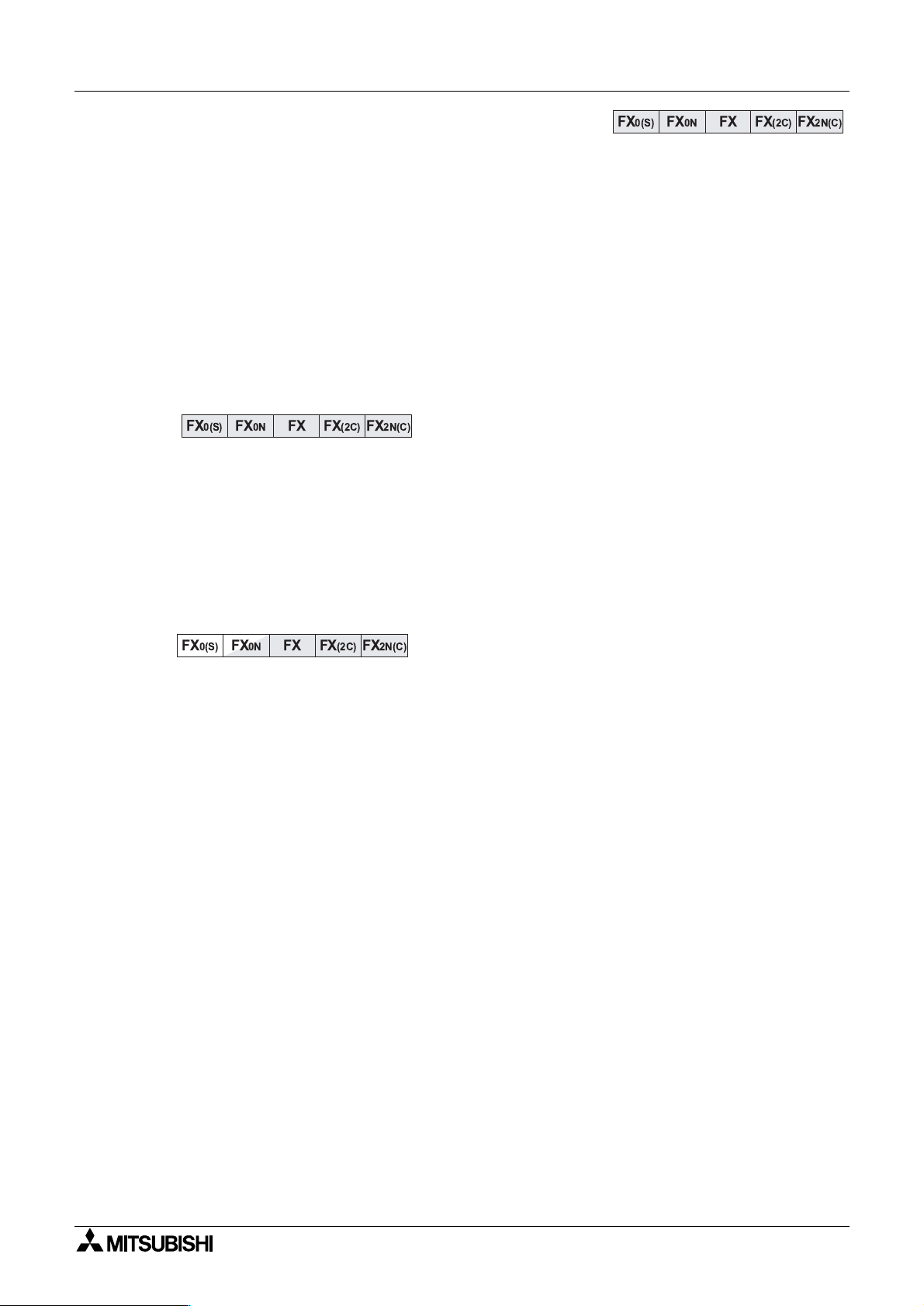
This manual covers all the functions of the hi
Controller (PLC). For this reason, the followin
to show which PLCs that section applies to;
Introduction 1
ives details on all aspects of operation and programming for FX, FX2C, FX0N,
and FX
2NC
programmable controllers (PLCs). For all information relating to
hest specification Programmable (Logic)
indicator is included in relevant section titles
FX
0(S)
- “FX
- “FX
0(S)
0N
FX FX
” - All FX0 and FX0S PLCs
” - All FX0N PLCs
(2C)
FX
0N
- “FX” - All FX and FX
- “FX
- - All FX
- “FX
(2C)
” - All FX and FX2 PLCs (CPU versions 3.07 or later)
2C
PLCs (see page 1-4)
2N(C)
” - All FX2N and FX
FX
2N(C)
2
PLCs (CPU ver 2.30 or earlier)
2NC
Shaded boxes indicate
the applicable PLC t
PLCs
pe
If an indicator box is half shaded, as shown to the
FX
0(S)FX0N
FX FX
(2C)
FX
2N(C)
left, this means that not all the functions described in
the current section appl
to that PLC. The text
explains in further detail or makes an independent
reference.
If there are no indicator boxes then assume the section applies to all PLC t
pes unless
otherwise stated.
3) FX famil
This is a generic term which is often used to describe all Programmable Controllers without
identif
4) CPU version numbers and pro
As Mitsubishi up
individual types or model names.
ramming support
rades each model different versions have different capabilities.
- Please refer to section 1.4 for details about version numbers and capabil it ies.
- Please refer to section 1.5 for details about peripheral support for each model.
1-1
Page 20
1.2 What is a Programmable Controller?
g
y
gg
g
y
g
gy
g
y
g
y
g
g
g
g
y
g
FX
0(S)
FX0N FX FX(2C)
FX2N(C)
FX
0(S)
FX0N FX FX(2C)
FX2N(C)
A Programmable Logic Controller (PLC or programmable controller) is a device that a user can
pro
ram to perform a series or sequence of events. These events are triggered by stimuli
(usuall
counted occur-rences. Once an ev ent tri
or OFF electronic control
will continuall
outputs at the programmed specific times.
called inputs) received at the PLC or through delayed actions such as time delays or
ear or the physical actuation of devices. A programmable controller
‘loop’ through its internal ‘user defined’ program waiting for inputs and givin
Introduction 1
ers, it actuates in the outside world by switching ON
Note on termin o lo
The term pro
control s
‘Pro
rammable Logic Controller ’, ‘PLC’ or ‘programmable controller ’ to de scribe the same
control s
stem under one descriptive na me. Sometimes engineers use the term
stem.
The construction of a pro
element where the pro
Processin
Unit or MPU. Other terms commonly heard to describe this device are ‘base unit’,
:
rammable controller is a generic word used to bring all the elements making the
rammable controller can be broken down into component parts. The
ram is loaded, s tored and pr ocessed is often known as th e Main
‘controller’ and ‘CPU’. The term CPU is a little misleadin
ma
contain local CPU devices. A Main CPU (or more correctly a Main Processing Unit)
controls these local CPUs throu
h a communication network or bus.
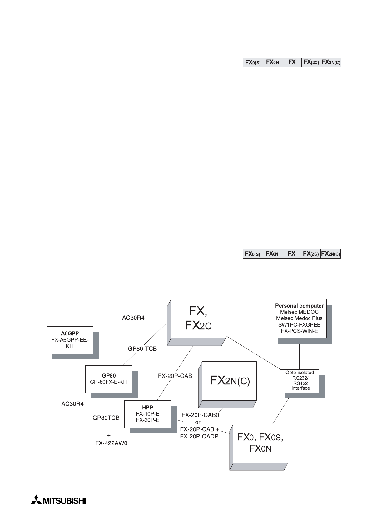
1.3 What do You Need to Program a PLC?
A variety of tools are available to program the Mitsubishi FX family of PLCs. Each of these
tools can use and access the instructions and devices listed in this manual for the identified
PLC.
FX
A6GPP
FX-A6GPP-EE-
KIT
FX,
2C
as todays more advanced products
Personal computer
Melsec MEDOC
Melsec Medoc Plus
SW1PC-FXGPEE
FX-PCS-WIN-E
GP80
GP-80FX-E-KIT
HPP
FX-10P-E
FX-20P-E
FX
2N(C)
Opto-isolated
RS232/
RS422
interface
FX0,FX0S,
FX
0N
1-2
Page 21

1.4 CPU version numbers
g
g
y
g
g
g
g
y
g
g
FX0(S) FX0N FX FX(2C) FX2N(C)
Over time Mitsubishi adds newer and better features to develop and enhance the products.
Because of the nature of PLCs, that can be likened to ‘industrial computers’, chan
sometimes occur within the units main CPU (Central Processin
similar to those experienced b
processor. The followin
functions and features added.
Introduction 1
es
Unit). These changes are
office and home computer users, that is, going to a version up
lists identify the CPU versions that had significant upgrades or new
1.4.1 FX
0N
CPU versions
CPU Ver 1.20
CPU Ver 1.40
1.4.2 FX and FX
CPU Ver 3.07
The followin
features were added:
Software control for protocol 1 and 4 communications with the FX
1:N network.
The followin
Software control for communications usin
features were added:
the FX0N-485ADP, peer to peer
(N:N) network.
2C
CPU versions
The following instructions were added:
ASCI (FNC82), CCD (FNC84), FLT (FNC49), HEX (FNC83), RS (FNC80),
SER (FNC61), SORT (FNC69), SQR (FNC48)
The following instructions were upgraded:
EI (FNC04), BMOV (FNC15), HSCS (FNC53), PLSY (FNC57),
FMOV (FNC16), MEAN (FNC45), ABSD (FNC62), DSW (FNC72),SEGL (74),
PR (FNC 77)
The following device ranges were added:
Input and output devices are independently addressable upto 256 points in
software. Total combined input and output points (hardware or software) is
256.
Auxiliar
Data re
Optional RAM File Re
relays increased to 1536 points (M0-M1535)
isters increased to 1000 points (D0-D999)
isters added, 2000 points (D6000 -D7999)
Pointers increased to 128 points (P0 - P127)
0N
-485ADP,
CPU Ver 3.11
CPU Ver 3.2
CPU Ver 3.30
The following instructions were added:
PID (FNC88)
The following features were added:
Software control for protocol 4 communications with th e FX-485ADP, 1:N
network.
The following features were added:
Software control for protocol 1 communications with th e FX-485ADP, 1:N
network.
The following instructions were phased out (removed):
ANRD (FNC91), ANWR (FNC92), BLK (FNC97), MCDE (FNC98), MNET
(FNC90)
1-3
Page 22
1.5 Special considerations for programming equipment
y
y
ying
y
g
g
g
FX
0(S)
FX0N FX FX(2C)
FX
2N(C)
g
g
y
Introduction 1
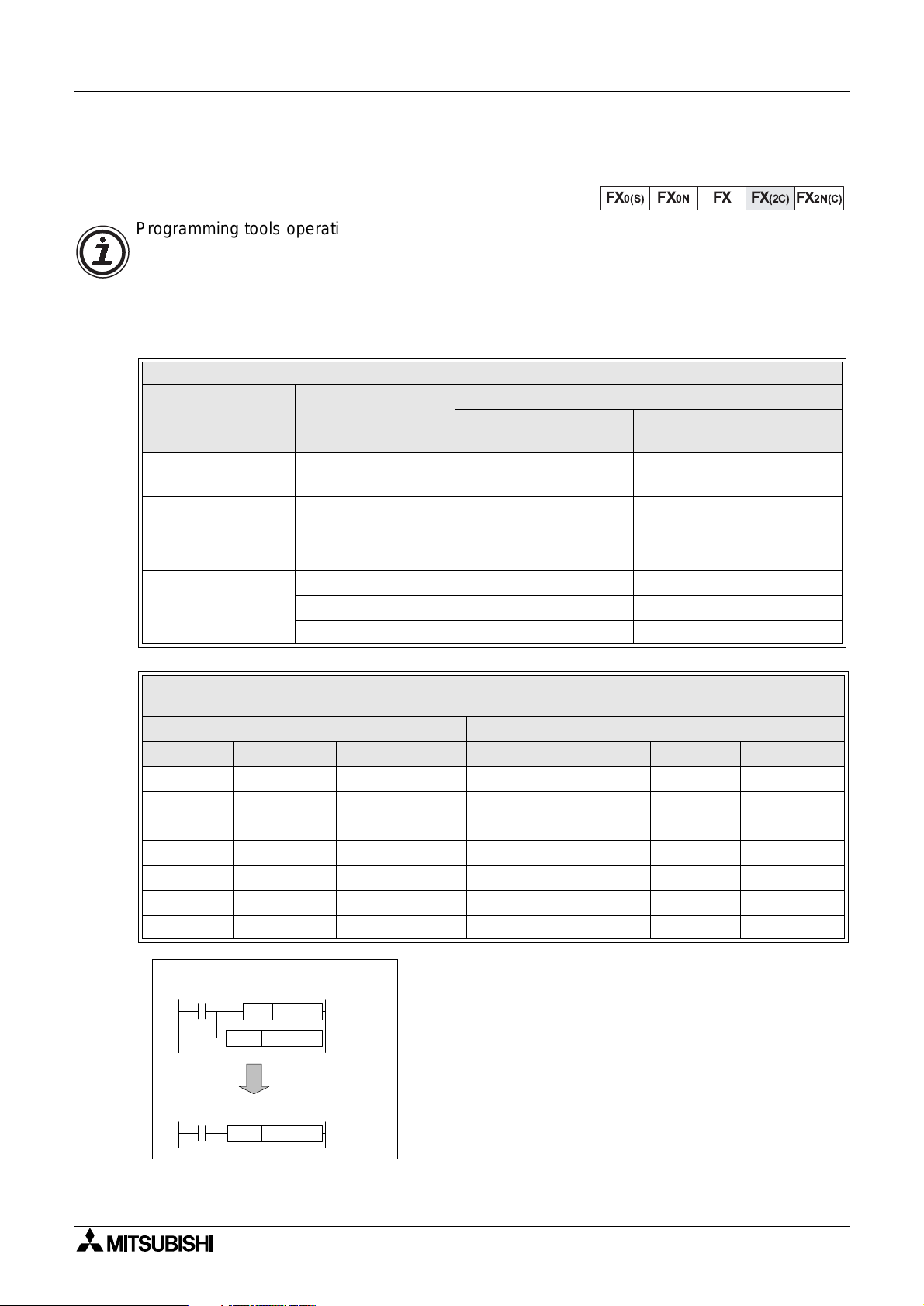
1.5.1 FX CPU version 3.07 or later and FX
Programming tools operating old system software can not access the new featur es added to
the FX CPU from version 3.07 (and available on all FX
certain ‘standard’ applied instructions in conjunction with special auxiliary coils (M coils) can
achieve the same ’effective instruction’ as the new instructions. The followin
which version of peripheral software will work directly with all of the ’new’ features and which
peripheral software versions require use of modified instructions.
Description Model Number
Hand held
pro
rammer (HHP)
HHP cassette FX-20P-MFXA-E V 1.20 from V 2.00
rammin
Pro
software
Data access units
FX-10P-E V 1.10 from V 2.00
FX-PCS/AT-E-KIT V 1.01 from V 2.00
FX-A6GPP-E-KIT V 1.00 from V 2.00
FX-10DU-E V 1.10 from V 2.00
FX-20DU-E V 1.10 from V 2.00
Other DU units from V 1.00
2C
Peripherals Table
System software version which will.......
....require the use of
auxiliary M coils
2C
units). However, programmin
tables identif
....program all instructions
directly
Existing Instruction And Special M Coil Combination To Mimic The Operation Of The
Identified Instruction
Existing FX instruction used to mimic the operation of......
Mnemonic FNC number Modifying M coil Mimicked instruction Mnemonic FNC Number
MOV 12 M8190 Square root SQR 48
MOV 12 M8191 Float FLT 49
RAMP 67 M8193 Data search SER 61
RAMP 67 M8194 RS232 instruction RS 80
FMOV 16 M8196 Hex to ASCII conversion ASCI 82
FMOV 16 M8197 ASCII to Hex conversion HEX 83
FMOV 16 M8195 Sum check CCD 84
Example usage
Using existing FX functions......
SET
M8190
D10
K36
MOV
to mimic......
This format is ver
correctl
.The user must program the ’mimic’ instruction
with the modif
before the instruction to be modified.
important for the instruction to operate
M coil in a SET instruction immediatel
SQR
K36
D10
1-4
Page 23
Introduction 1
y
y
g
g
g
g
g
g
g
g
g
g
g
FX
0(S)
FX0N FX FX(2C)
FX
2N(C)
g
y
g
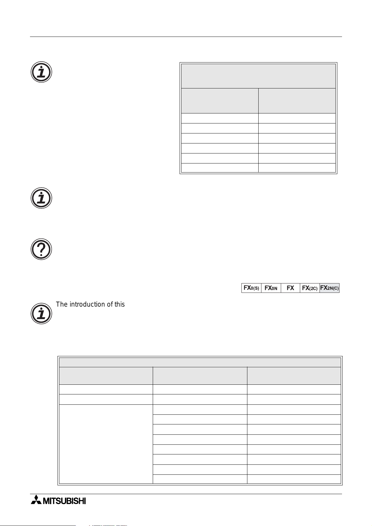
Using the new Interrupt Pointers:
To pro
throu
instruction with older pro
ram new Interrupt Pointer s I010
h I060 in to the HSCS (FNC 53)
rammin
equipment, substitute the followin
special M codes for the appropriate
Interrupt Pointer; see the table ri
ht.
Existing Instruction And Special M Coil
Combination To Mimic The Operation
Of The Identified Interrupt pointer
Existing Auxiliary Coil
used to replace the ident i-
fied Interrupt Pointer
M8181 I010
M8182 I020
M8183 I030
M8184 I040
M8185 I050
M8186 I060
Interrupt Pointer
Using M8198 with the BMOV instruction:
With old software and peripherals, file re
BMOV (FNC 15) instruction. To BMOV data into file re
isters can not be used as a destination device in the
isters with old equipment set special M
coil M8198 on. This switches the source and destination parameters; i.e., the source is then
treated as the destination and the destination becomes the source.
General note:
I
pro
sections, will apply.
1.5.2 FX
The introduction of this CPU provides the FX user with many new devices and instructions. To
use the full features of the FX
pro
However, because of the downward compatibilit
existin
CPU ver 3.30 units.
nore the special programming techniques identified in this section if using updated
ramming software or peripherals; then normal operation, as identifiedin the followin
2N(C)
CPU all versions
2N(C)
units the user must upgrade older software and hardware
ramming tools.
of the FX
programming tools for use with FX
Description Model Number
Hand held programmer (HHP) FX-10P-E from V 3.00
HHP cassette FX-20P-MFXA-E from V 3.00
FX-10DU-E from V 4.00
FX-20DU-E Supports up to FX devices onl
FX-25DU-E from V 2.00
FX-30DU-E from V 3.00
Data access units
FX-40DU-E(S) Supports up to FX devices onl
FX-40DU-TK-ES from V 3.00
FX-50DU-TK(S)-E from V 2.10
F940GOT-SWD(LWD)-E All versions
2N(C)
units up to the equivalent functionality of FX
Peripherals Table
2N(C)
, it is not necessary to upgrade
System software version with
full support for FX
2N(c)
1-5
Page 24

MEMO
Introduction 1
1-6
Page 25
FX Series Programmable Controllers Basic Program Instructions 2
1 Introduction
2 Basic Program Instructions
3 STL Programming
4 Devices in Detail
5 Applied Instructions
6 Diagnostic Devices
7 Instruction Execution Times
8 PLC Device Tables
9 Assigning System Devices
10 Points of Technique
11 Index
Page 26

FX Series Programmable Controllers Basic Program Instructions 2
g
g
g
g
g
g
g
g
Chapter Contents
2. Basic Pro
ram Instructions ...................................................................2-1
2.1 What is a Program?.... .. ... .. .. .. ... .. .. .... ... .. .. .. .. ... .. .. .. .. ..... .. .. .. ... .. .. .. ... .. .. .... ... .. .. .. .. ...2-1
2.2 Outline of Basic Devices Used in Pro
2.3 How to Read Ladder Lo
ic..................................................................................2-2
ramming..................................................2-1
2.4 Load, Load Inverse ..............................................................................................2-3
2.5 Out.......................................................................................................................2 -4
2.5.1 Timer and Counter Variations ...................................................................................2-4
2.5.2 Double Coil Desi
nation..... ...... ....... ...... ....... ...... ...... ....... ...... ....... ...... ....... ...... ....... ...2-5
2.6 And, And Inverse.................................................................................................2-6
2.7 Or, Or Inverse......................................................................................................2-7
2.8 Load Pulse, Load Trailin
2.9 And Pulse, And Trailin
2.10 Or Pulse, Or Trailin
Pulse. .. .. ................ .. .. ............... ... .. .............................2-8
Pulse.............................................................................2-9
Pulse................................................................................2-10
2.11 Or Block.............................................................................................................2-11
2.12 And Block ..........................................................................................................2-12
2.13 MPS, MRD and MPP......................................... .. .. .. ..........................................2-13
2.14 Master Control and Reset................................................... ...............................2-15
2.15 Set and Reset................. ................................. ................................. .................2-17
2.16 Timer, Counter(Out & Reset)................................................... ..........................2-18
2.16.1 Basic Timers, Retentive Timers And Counters........................................................2-18
2.16.2 Normal 32 bit Counters ...........................................................................................2-19
2.16.3 Hi
h Speed Counters ..............................................................................................2-19
2.17 Leading and Trailing Pulse................................................................................2-20
2.18 Inverse...............................................................................................................2-21
2.19 No Operatio n . .. .. ............................... ... .. ............................... .. .. .........................2-22
2.20 End ....... .. ............................................... .. .. ............................... .. ... ............... .. .. .2 -23
Page 27
g
g
g
g
g
y
y
y
y
y
g
g
FX Series Programmable Controllers
2. Basic Program Instructions
2.1 What is a Program?
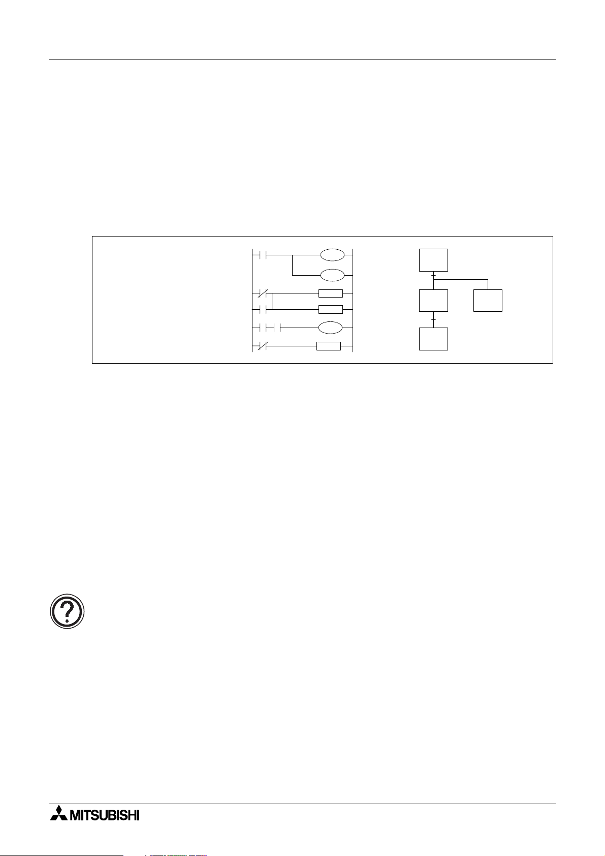
A program is a connected series of instructions written in a language that the PLC can
understand. There are three forms of pro
pro
ramming tools can work in all programming forms. Generally hand held programmin
panels only work with instruction format while most graphic programming tools will work with
both instruction and ladder format. Specialist pro
pro
ramming.
Basic Program Instructions 2
ram format; instruction, ladder and SFC/STL. Not all
ramming software will also allow SFC style
LD
OUT
AND
SET
LD
OUT
X10
Y7
M38
S5
X21
T01
K40
Instruction format Ladder Format SFC Format
2.2 Outline of Basic Devices Used in Programming
There are six basic programming devices. Each device has its own unique use. To enable
quick and eas
- X: This is used to identif
- Y: This is used to identif
- T: This is used to identif
- C: This is used to identif
- M and S: These are used as internal operation fla
identification each device is assigned a single reference letter;
all direct, physical inputs to the PLC.
all direct, physical outputs from the PLC.
a timing device which is contained within the PLC.
a counting device which is contained within the PLC.
s within the PLC.
All of the devices mentioned above are known as ‘bit devices’. This is a descriptive title tellin
the user that these devices only have two states; ON or OFF, 1 or 0.
Detailed device information:
• Chapter 4 contains this information in detail. However, the above is all that is
required for the rest of this chapter.
2-1
Page 28
FX Series Programmable Controllers Basic Program Instructions 2
g
g
y
y
g
g
g
y
y
y
g
g
g
2.3 How to Read Ladder Logic
Ladder logic is very closely associated to basic relay logic. There are both contacts and coils
that can be loaded and driven in different confi
the same.
A coil drives direct outputs of the PLC (ex. a Y device) or drives internal timers, counters or
s (ex. T, C, M and S devices). Each coil has associated contacts. These contacts are
fla
available in both “normall
open” (NO) and “normally closed” (NC) configurations.
urations. However, the basic principle remains
The term “normal(l
)” refers to the status of the contacts when the coil is not energized. Usin
a relay analogy, when the coil is OFF, a NO contact would have no current flow, that is, a load
bein
supplied through a NO contact w ould not o perate. Ho wever, a NC contact w ould allo w
current to flow, hence the connected load would be active.
Activatin
the coil reverses the contact status , that is, the current would flow in a NO contac t
and a NC contact would inhibit the flow.
Ph
sical inputs to the PLC (X devi ces) have n o programmable coil. These devices may only be
used in a contact format (NO and NC t
pes are available).
Example:
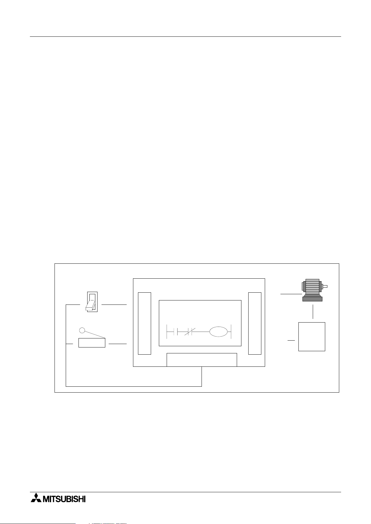
Because of the close rela
association, ladder logic programs can be read as current flowin
from the left ve rtical line to the right vertical line. This current must pass through a series of
contact representations such as X0 and X1 in order to switch the output coil Y0 ON. Therefore,
in the example shown, switchin
X0 ON causes the output Y0 to also switch ON. If however,
the limit switch X1 is activa tes, the output Y0 turns OFF. This is because the con nection
between the left and the ri
Toggle switch
X0
X1
Limit switch
ht vertical lines breaks so there is no current flow.
Programmable Controller
Y0
I
N
P
U
T
PC Program
X0 X1
Y0
DC Power Supply
O
U
T
P
U
COM
T
(Y0)
Motor
AC
Power
Supply
2-2
Page 29
FX Series Programmable Controllers Basic Program Instructions 2
y
g
g
y
y
g
y
y
g
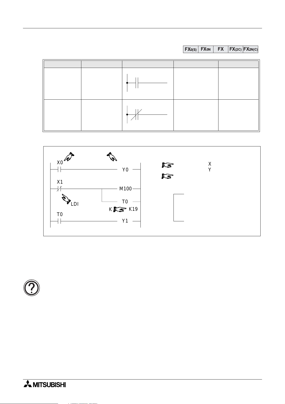
2.4 Load, Load Inverse
Mnemonic Function Format Devices Program steps
Initial lo
LD
(LoaD)
LDI
(LoaD Inverse)
Program example:
X0
X1
T0
operation contact
t
pe NO
(normall
Initial lo
operation contact
t
pe NC
(normall
LDI
ical
open)
ical
closed)
K
Y0
M100
T0
Y1
K19
FX
X, Y, M, S, T, C 1
X, Y, M, S, T, C 1
0
1
2
3
4
7
8
FX0N FX FX(2C)
0(S)
LD
OUT
LDI
OUT
OUT
SP
LD
OUT
X
Y
X
M
T
K
T
Y
100
0
0
1
0
19
0
1
When using hand held
programmers, the space key
needs to be pressed to enable
the constant to be entered.
FX2N(C)
Basic points to remember:
- Connect the LD and LDI instructions directl
- Or use LD and LDI instructions to define a new block of pro
to the left hand bus bar.
ram when using the ORB
and ANB instructions (see later sections).
The OUT instruction:
• For details of the OUT instruction (including basic timer and counter variations)
please see over the followin
page.
2-3
Page 30
FX Series Programmable Controllers Basic Program Instructions 2
y
y
g
g
y
g
y
gg
g
g
y
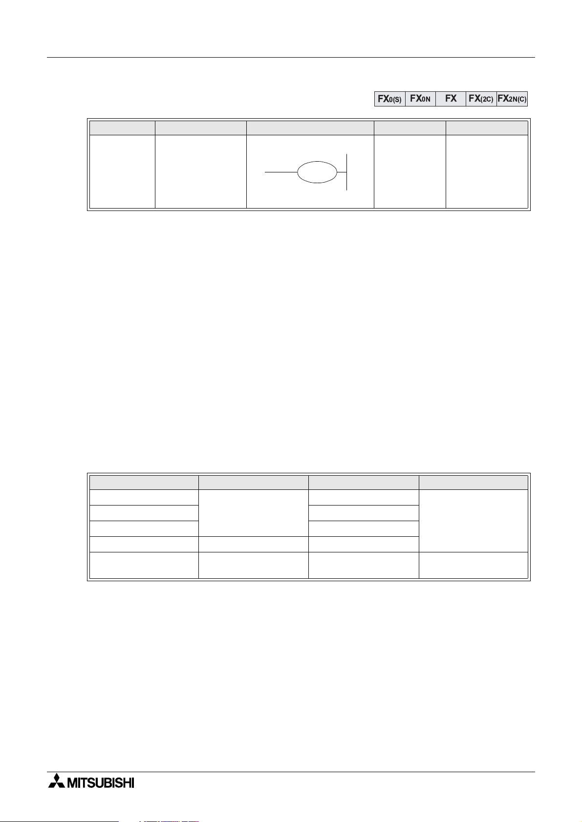
2.5 Out
Mnemonic Function Format Devices Program steps
OUT
(OUT)
Final lo
operation t
drive
Basic points to remember:
- Connect the OUT instruction directl
- It is not possible to use the OUT instruction to drive ‘X’ t
- It is possible to connect multiple OUT instructions in parallel (for example see the
previous pa
2.5.1 Timer and Counter Variations
When confi
uring the OUT instruction for u se as either a timer (T) or counte r (C) a consta nt
must also be entered. The constant is identified b
pa
e; T0 K19).
In the case of a timer, the constant “K” holds the duration data for the timer to operate, i.e. if a
100 msec timer has a constant o f “K100” it will be (100 5 100 msec) 10 s econds before the
timer coil activates.
With counters, the constant identifi es how ma n
before the counter coil activates. For example, a counter with a constant of “8” must be
tri
ered 8 times before the counter coil finally energizes.
The followin
table identifies some basic parameter data for various timers and counters;
ical
pe coil
e; M100/T0 configuration)
FX
Y, M, S, T, C
FX0N FX FX(2C)
0(S)
Y, M:1
S, special M
coils: 2
T:3
C (16 bit): 3
C (32 bit): 5
to the right hand bus bar.
pe input devices.
the letter “K” (for example see previous
times the counter must be pulsed or triggered
FX2N(C)
Timer/Counter Setting constant K Actual setting Program steps
1 msec Timer
10 msec Timer 0.01 to 327.67 sec
100 msec Timer 0.1 to 3276.7 sec
16 bit Counter 1 to 32,767 1 to 32,767
32 bit Counter
1 to 32,767
-2,147,483,648 to
2,147,483,647
0.001 to 32.767 sec
-2,147,483,648 to
2,147,483,647
3
5
2-4
Page 31

FX Series Programmable Controllers Basic Program Instructions 2
g
g
g
g
g
g
g
g
g
g
y
g
y
g
g
g
g
g
g
g
g
g
g
g
2.5.2 Double Coil Designation
X1
1.
Y3
Double or dual coilin
practice. Usin
same device can cause the pro
operation to become unreliable. The example
pro
ram shown opposite identifies a double
is not a recommended
multiple output coils of the
ram
coil situation; there are two Y3 outputs. The
Y3
Y4
followin
sequence of events will occur when
inputs X1 = ON and X2 = OFF;
2.
1.The first Y3 tuns ON because X1 is ON. The
X2
Y3
contacts as sociated with Y3 als o ener
when the coil of output Y 3 ener
izes. Hence,
ize
output Y4 turns ON.
2.The last and most important line in this
pro
ram looks at the status of input X2.
If this is NOT ON then the second Y3 coil does NOT activate. Therefore the status of the Y3
coil updates to reflect this new situation, i.e. it turns OFF. The final outputs are then Y3 = OFF
and Y4 = ON.
Use of dual coils:
•Always check programs for incidents of dual coiling. If there are dual coils the
pro
ram will not operate as expected - possibly resulting in unforeseen physical
The last coil effect:
• In a dual coil designation, the coil operation designated last is the effecti ve coil. That
is, it is the status of the previous coil that dictates the behavior at the current point in
the pro
1
5
: Input ON state NOT reco
: Input ON state reco
: Input OFF state NOT reco
: 1 pro
: Input processin
: Output processin
: A full pro
ram processin
ram.
t secs
4
6
ram scan/operation cycle
nized
4
7
nized
nized
Input durations:
2
3
The ON or OFF duration of the PLC inputs
must be lon
er than the operation cycle
time of the PLC.
Takin
response dela
duration must be lon
the operation c
a 10 msec (standard input filter)
into account, the ON /OFF
er than 20 msec if
cle (scan time) is 10 msec.
Therefore, in this example, input pulses of
more than 25Hz (1sec/(20msec ON +
20msec OFF)) cannot be sensed.
There are applied instructions provided to
handle such hi
h speed input requests.
2-5
Page 32

FX Series Programmable Controllers Basic Program Instructions 2
y
g
g
g
y
y
y
g
g
g
2.6 And, And Inverse
Mnemonic Function Format Devices Program steps
AND
(AND)
ANI
(AND Inverse)
Program example:
X2
Y3
ANI
Serial connection
of NO (normall
open) contacts
Serial connection
of NC (normall
closed) contacts
X0
X3
AND
T1
FX
X, Y, M, S, T, C 1
X, Y, M, S, T, C 1
Y3
M101
FX0N FX FX(2C)
0(S)
LD
0
AND
1
OUT
2
LD
3
ANI
4
OUT
5
6
AND
OUT
7
X
X
Y
Y
X
M
T
Y
FX2N(C)
2
0
3
3
3
101
1
4
Y4
AND
Basic points to remember:
- Use the AND and ANI instructions for serial connec ti on of cont acts. As man
required can be connected in series (see follo win
- The output processin
to a coil, through a contact, after wri ti ng the initial OUT instruction
is called a “follow-on” output (for an example see the pro
on outputs are permitted repeatedl
as long as the output order is correct.
point headed “Peripheral limitati ons” ).
ram above; OUT Y4). Follow-
Peripheral limitations:
• The PLC has no limit to the number of contacts connected in series or in parallel.
However, some pro
or print the pro
line or run
of ladder program to contain up to a maxi mum of 10 contacts and 1 coil.
Also, keep the number of follow-on outputs to a maximum of 24.
ramming panels, screens and pri nters wil l not be able to displ ay
ram if it exceeds the limit of the hardware. It is preferab le for each
contacts as
2-6
Page 33

FX Series Programmable Controllers Basic Program Instructions 2
y
y
g
g
g
2.7 Or, Or Inverse
Mnemonic Function Format Devices Program steps
OR
(OR)
ORI
(OR Inverse)
Program example:
X4
X6
M102
Y5
M103
Parallel
connection of NO
(normall
open)
contacts
Parallel
connection of NC
(normall
closed)
contacts
OR
ORI
X7
X10
Y5
M103
FX
X, Y, M, S, T, C 1
X, Y, M, S, T, C 1
FX0N FX FX(2C)
0(S)
LD
0
OR
1
ORI
2
OUT
3
LDI
4
AND
5
6
OR
ANI
7
8
9OROUT
X
X
M
Y
Y
X
M
X
M
M
FX2N(C)
4
6
102
5
5
7
103
10
110
103
M110
Basic points to remember:
- Use the OR and ORI instructions for parallel connection of contacts. To connect a block
that contains more than one contact connected in series to another circuit block in
parallel, use an ORB instruction.
- Connect one side of the OR/ORI instruction to the left hand bus bar.
Peripheral limitations:
• The PLC has no limit to the number of contacts connected in series or in parallel.
However, some pro
or print the pro
line or run
of ladder program to contain up to a maximum of 10 contacts and 1 coil.
Also keep number of follow-on outputs to a maximum of 24.
ramming panels, screens and printers will not be able to display
ram if it exceeds the limit of the hardware. It is preferab le for each
2-7
Page 34

FX Series Programmable Controllers Basic Program Instructions 2
y
g
g
g
g
g
g
y
g
g
g
y
g
FX
2.8 Load Pulse, Load Trailing Pulse
Mnemonic Function Format Dev ices Program steps
FX
0(S)
FX0N FX FX(2C)
2N(C)
Initial logical
LDP
(LoaDPulse)
operation Risin
edge
X, Y, M, S, T, C 2
pulse
LDF
(LoaD Falling
pulse)
Program example:
X0
X1
X0
Initial logical
operation Fallin
/ trailin
edge
pulse
LDP
LDF
M100
Y0
X, Y, M, S, T, C 2
0LDP X 0
2OR X 1
3 OUT M 100
4LDF X 0
6 OUT Y 0
Basic points to remember:
- Connect the LDP and LDF instructions directl
- Or use LDP and LDF instructions to define a new block of pro
to the left hand bus bar.
ram when using the ORB
and ANB instructions (see later sections).
- LDP is active for one pro
- LDF is active for one pro
ram scan after the associated device switches from OFF to ON.
ram scan after the associated device switches from ON to
OFF.
Single Operation flags M2800 to M3071:
• The pulse operation instructions, when used with auxiliary relays M2800 to M3071,
onl
activate the first instruction encountered in the program scan, after the point in
the pro
remain inactive.
• This is useful for use in STL pro
operation usin
•An
For more details please see pa
ram where the device changes. Any other pulse operation instructions will
rams (see chapter 3) to perform single step
a single device.
other instructions (LD, AND, OR, etc.) will operate as expected.
e 4-5.
2-8
Page 35

FX Series Programmable Controllers Basic Program Instructions 2
g
g
g
g
g
g
g
FX
2.9 And Pulse, And Trailing Pulse
Mnemonic Function Format Dev ices Program steps
FX
0(S)
FX0N FX FX(2C)
2N(C)
ANP
(ANd Pulse)
ANF
(ANd Falling
pulse)
Serial connection
of Risin
pulse
Serial connection
of Fallin
trailin
pulse
Program example:
M40
X1
X0
edge
/
edge
T10
C0
ANP
ANF
M100
Y4
X, Y, M, S, T, C 2
X, Y, M, S, T, C 2
0LD M40
1OR X 1
2 ANP T 10
4 OUT M 100
5LDF X 0
6ANF C 0
8 OUT Y 4
Basic points to remember:
- Use the ANDP and ANDF instructions for the serial connection of pulse contacts .
-Usa
- ANP is active for one pro
e is the same as for AND and ANI; see earlier.
ram scan after the associated device switches from OFF to
ON.
- ANF is active for one pro
ram scan after the associated device switches from ON to
OFF.
Single operation flags M2800 to M3071:
• When used with flags M2800 to M3071 only the first instruction will activate. For
details see pa
e 2-8
2-9
Page 36

FX Series Programmable Controllers Basic Program Instructions 2
g
g
g
g
g
g
g
FX
2.10 Or Pulse, Or Trailing Pulse
Mnemonic Function Format Dev ices Program steps
FX
0(S)
FX0N FX FX(2C)
2N(C)
Parallel
ORP
(OR Pulse)
connection of
Risin
edge
X, Y, M, S, T, C 2
pulse
ORF
(OR Falling
pulse)
Parallel
connection of
Fallin
ed
Program example:
M40
X1
X0
Y7
/ trailing
e pulse
ORP
M24
X1
ORF
SET M50
Y4
X, Y, M, S, T, C 2
0LD M40
1 ORP X 1
3 SET M 50
4LD X 0
5 AND M 24
6LD Y 7
7 ORF X 1
9 ORB
10 OUT Y 4
Basic points to remember:
- Use the ORP and ORF instructions for the parallel connection of pulse contacts.
-Usa
- ORP is active for one pro
e is the same as for OR and ORI; see earlier.
ram scan after the associated device switches from OFF to
ON.
- ORF is active for one pro
ram scan after the associated device switches from ON to
OFF.
Single operation flags M2800 to M3071:
• When used with flags M2800 to M3071 only the first instruction will activate. For
details see pa
e 2-8
2-10
Page 37

FX Series Programmable Controllers Basic Program Instructions 2
y
y
g
g
g
g
g
g
g
2.11 Or Block
Mnemonic Function Format Devices Program steps
ORB
(OR Block)
Program example:
X0 X1
X2 X3
X4 X5
Parallel connection
of multiple contact
circuits
Y6
ORB
ORB
FX
0(S)
N/A 1
Recommended sequential
programming method
0
LD
1
AND
2
LD
3
AND
ORB
4
5
LDI
6
AND
ORB
7
8 OUT
0
X
1
X
2
X
3
X
X
4
X
5
Y
6
FX0N FX FX(2C)
Non-preferred batch
programming method
0
LD
1
AND
2
LD
3
AND
4
LDI
5
AND
6
ORB
ORB
7
8 OUT
FX2N(C)
0
X
1
X
2
X
3
X
X4
X
5
Y6
Basic points to remember:
- An ORB instruction is an independent instruction and is not associated with an
number.
- Use the ORB instruction to connect multi-contact circuits (usuall
the precedin
circuit in parallel. Serial circuit blocks are those in which more than one
serial circuit blocks) to
contact connects in series or the ANB instruction is used.
- To declare the startin
completin
the serial circuit block, connect it to the preceding block in parallel using the
point of the circuit block use a LD or LDI instruction. After
ORB instruction.
Batch processing limitations:
• When using ORB instructions in a batch, use no more than 8 LD and LDI instr uctions
in the definition of the pro
result in a pro
ram error (see the right most program listing).
ram blocks (to be connected in parallel). Ignoring this will
Sequential processing limit at ions :
• There are no limitations to the number of parallel circu it s wh en using an ORB
instruction in the sequential processin
listin
).
configuration (see the left most program
device
2-11
Page 38

FX Series Programmable Controllers Basic Program Instructions 2
y
y
g
g
g
g
g
g
2.12 And Block
Mnemonic Function Format Devices Program steps
ANB
(ANd Block)
Program example:
ANB
X0
X1
X3
Serial connection
of multiple
parallel circuits
LD
X2 X3
X4 X5
X6
Y7
ORB
FX
FX0N FX FX(2C)
0(S)
N/A 1
Recommended sequential
programming method
0
LD
1
OR
2
LD
3
AND
4
LDI
5
AND
6
ORB
7
OR
ANB
8
X
X
X
X
X
X
X
910OR
OUTXY
FX2N(C)
0
1
2
3
4
5
6
3
7
Basic points to remember:
- An ANB instruction is an independent instruction and is not associated with an
number
- Use the ANB instruction to connect multi-contact circuits (usuall
to the precedin
circuit in series. Parall el circuit blocks are those in which more than one
parallel circuit blocks)
contact connects in parallel or the ORB instruction is used.
- To declare the startin
completin
the parallel circuit block, connect it to the preceding block in series using the
point of the circuit block, use a LD or LDI instruction. After
ANB instruction.
Batch processing limitations:
• When using ANB instructions in a batch, use no mor e than 8 LD and L DI i nstruc tions
in the definition of the pro
result in a pro
ram error (see ORB explanation for example).
ram blocks (to be connected in parallel). Ignoring this will
Sequential processing limit at ions :
• It is possible to use as many ANB instructions as necessary to connect a number of
parallel circuit blocks to the precedin
block in series (see the program listing).
device
2-12
Page 39

FX Series Programmable Controllers Basic Program Instructions 2
y
y
y
y
y
y
g
g
g
2.13 MPS, MRD and MPP
Mnemonic Function Format Devices Program steps
Stores the current
MPS
(Point Store)
MRD
(Read)
MPP
(PoP)
Basic points to remember:
- Use these instructions to connect output coils to the left hand side of a contact.
Without these instructions connections can onl
last contact.
- MPS stores the connection point of the ladder circuit so that further coil branches can
recall the value later.
result of the
internal PLC
operations
Reads the current
result of the
internal PLC
operations
Pops (recalls and
removes) the
currentl
result
stored
MPS
MRD
MPP
FX
FX0N FX FX(2C)
0(S)
FX2N(C)
N/A 1
N/A 1
N/A 1
be made to the right hand side of the
- MRD recalls or reads the previousl
stored connection point data and forces the next
contact to connect to it.
- MPP pops (recalls and removes) the stored connection point. First, it connects the next
contact, then it removes the point from the temporar
- For ever
MPS instruction there MUST be a corresponding MPP instruction.
storage area.
- The last contact or coil circuit must connect to an MPP instruction.
-At an
programming step, the number of active MPS-MPP pairs must be no greater than
11.
MPS, MRD and MPP usage:
• When writing a program in ladder format, programming tools automatically add all
MPS, MRD and MPP instructions at the pro
instruction pro
• When writin
ram is viewed, the MPS, MRD and MPP instructions are present.
a program in instruction f ormat, it is entirely down to the user to enter all
relevant MPS, MRD and MPP instructions as required.
ram conversion stage. If the generated
2-13
Page 40

FX Series Programmable Controllers Basic Program Instructions 2
Multiple program examples:
X0 X1
MPS
MRD
MPP
X2
X3
X5
X7
X4
X6
X10
Y0
Y1
Y2
Y3
10
11
0
LD
MPS
1
2
LD
3
OR
4
ANB
5
OUT
6
MRD
7
LD
8
AND
9
LD
AND
0
X
1
X
2
X
Y
0
X
3
4
X
5
X
6
X
ORB
12
13
14
15
16
17
18
19
20
ANB
OUT
MPP
AND
OUT
LD
OR
ANB
OUT
1
Y
7
X
2
Y
X
10
X
11
3
Y
X11
X0 X1
MPS
MPP
MPS
X4 X5
MPP
MPS
MPP
X0 X1 X2 X3 X4
MPS
X2
X3
X6
Y0
Y1
Y2
Y3
Y0
Y1
Y2
Y3
Y4
0
LD
MPS
1
2
AND
MPS
3
4
AND
5
OUT
6
MPP
7
AND
8
OUT
LD
0
MPS
1
AND
2
MPS
3
AND
4
MPS
5
6
AND
MPS
7
AND
8
X
0
X
1
X
2
Y
0
X
3
Y
1
0
X
1
X
2
X
3
X
4
X
MPP
9
10
AND
MPS
11
12
AND
13
OUT
MPP
14
15
AND
16
OUT
OUT
9
MPP
10
11
OUT
MPP
12
OUT
13
MPP
14
OUT
15
MPP
16
17 OUT
4
X
X
5
Y
2
X
6
Y
3
0
Y
1
Y
2
Y
3
Y
4
Y
MPP
2-14
Page 41

FX Series Programmable Controllers Basic Program Instructions 2
g
g
y
y
g
j
2.14 Master Control and Reset
Mnemonic Function Format Devices Program steps
MC
(Master
Control)
MCR
(Master
Control Reset)
Program example:
X0
M100N0
X1
X2
Denotes the start
of a master control
block
Denotes th e end of
a master control
block
M100N0MC
Y0
Y1
MC N
MCR N
FX
FX0N FX FX(2C)
0(S)
Y, M (no special
M coils allowed)
N denotes the
nest level (N0 to
N7)
N denotes the
nest level (N0 to
N7) to be reset.
0
1
4
5
6
7
8
LD
MC
SP
LD
OUT
LD
OUT
MCR
X
N
M
X
Y
X
Y
N
FX2N(C)
3
2
0
0
100
1
0
2
1
0
Note: SP - space key
N0MCR
N - nest level of MC (N0 to N7)
Basic points to remember:
- After the execution of an MC instructi on, the bus l ine (LD, LDI po int) s hif ts to a point af te r
the MC instruction. An MCR instruction returns this to the ori
inal bus line.
- The MC instruction also includes a nest level pointer N. Nest levels are from the ran
N0 to N7 (8 points). The top nest level is ‘0’ and the deepest is ‘7’.
- The MCR instruction resets eac h nest l eve l. When a nes t lev el is re set, it al so resets ALL
deeper nest levels. For example, MCR N5 resets nest levels 5 to 7.
- When input X0=ON, all instructions between the MC and the MCR instruction execute.
- When input X0=OFF, none of the instruction between the MC and MCR instruction
execute; this resets all devices except for retentive timers, counters and devices driven
SET/RST instructions.
b
- The MC instruction can be used as man
number Y and M. Usin
the same device number twice is proces sed as a double coil
times as necessary, by changing the device
(see section 2.5.2). Nest levels can be duplicated but when the nest level resets, ALL
occurrences of that level reset and not
ust the one specified in the local MC.
e
2-15
Page 42

FX Series Programmable Controllers Basic Program Instructions 2
g
g
g
Nested MC program example:
X0
A
M100N0MC
B
C
D
M100N0
M101N1
M102N2
X1
X2
X3
X4
X5
Level N0: Bus line (B) active when X0
is ON.
Y0
M101N1MC
Level N1: Bus line (C) active when
both X0 and X2 are ON.
Y1
M102N2MC
Level N2: Bus line (D) active when
X0,X2 and X4 are ON.
Y2
C
A
B
X6
X7
X10
MCR
MCR
MCR
N2
Y3
N1
Y4
N0
Y5
Level N1: MCRN2 executes and
restores bus line (C). If the MCR had
reset N0 then the ori
would now be active as all master
controls below nest level 0 would reset.
Level N0: MCRN1 executes and
restores bus line (B).
Initial state: MCR N0 ex ecutes and
restores the in it ia l b u s li ne (A) .
Output Y5 turns ON/OFF acco rdin
the ON/OFF state of X10, r e
the ON/OFF status of inputs X0, X2 or
X4.
inal bus bar (A)
to
ardless of
2-16
Page 43

FX Series Programmable Controllers Basic Program Instructions 2
g
g
y
y
g
y
y
g
X0
X1
Y0
2.15 Set and Reset
Mnemonic Function Format Devi ces Program steps
SET
(SET)
RST
(ReSeT)
Program example:
X0
X1
X2
X3
X4
X5
X6
Sets a bit device
permanentl
Resets a bit
device
permanentl
OFF
ON
SET Y0
RST Y0
SET M0
RST M0
SET S0
RST S0
RST D0
SET
RST
FX
Y, M, S
Y, M, S, D, V, Z
(see section
2.16 for timers
and counters
T,C)
FX0N FX FX(2C)
0(S)
0
1
2
3
4
5
6
7
8
9
10
11
12
13
Y,M:1
S, special M
coils:2
D, special D
isters, V and
re
Z:3
LD
SET
LD
RST
LD
SET
LD
RST
LD
SET
LD
RST
LD
RST
X
Y
X
Y
X
M
X
M
X
S
X
S
X
D
FX2N(C)
0
0
1
0
2
0
3
0
4
0
5
0
6
0
Basic points to remember:
- Turnin
Y0 remains ON even after X0 turns OFF.
- Turnin
Y0 remains OFF even after X1 turns
OFF.
- SET and RST instructions can be used
for the same device as man
necessar
However, the last instruction activated
determines the current status.
- It is also possible to use the RST instruction to reset the contents of data devices such
as data re
device.
ON X0 causes Y0 to turn ON.
ON X1 causes Y0 to turn OFF.
times as
.
isters, index registers etc. The effect is similar to moving ‘K0’ into the data
Resetting timers and counters:
• Please see next page.
2-17
Page 44

FX Series Programmable Controllers Basic Program Instructions 2
y
y
g
g
g
y
2.16 Timer, Counter (Out & Reset)
Mnemonic Function Format Devices Program steps
OUT
(OUT)
RST
(ReSeT)
Program example:
X0
X1
T246
X2
X3
X4
Driving timer or
counter coils
Resets timer and
counter, coils
contacts and
current values
RST T246
RST
T246
K1234
Y0
M8200
C200
C200
D0
FX
FX0N FX FX(2C)
0(S)
32 bit
T, C
counters:5
Others: 3
T, C
(see section
RST
2.15 for other
T, C:2
resetable
devices)
2.16.1Basic Timers, Retentive Timers And Counters
These devices can all be reset at an
driving the RST instruction (with the number
of the device to be reset).
On resettin
current value re
, all active contacts, coils and
isters are reset for the
selected device. In the example, T246, a
1msec retentive timer, is activate while X1 is
ON. When the current value of T246 reaches
the preset ‘K’ value, i.e. 1234 , the timer co il for
T246 will be activated. This drives the NO
contact ON. Hence, Y0 is switched ON.
Tur n i n
manner described previousl
ON X0 will reset timer T246 in the
.
Because the T246 contacts are reset, the
output Y0 will be turned OFF.
FX2N(C)
time b
C200
Y1
Retentive timers:
• For more information on retentive timers please see page 4-17.
2-18
Page 45

FX Series Programmable Controllers Basic Program Instructions 2
g
g
y
g
g
g
y
g
g
g
g
g
g
g
g
X10
X11
RST
X12
K/D
C
M8
C
C
Y2
y
g
g
2.16.2 Normal 32 bit Counters
The 32 bit counter C200 counts (up-count, down-count) accordin
M8200. In the example pro
number of OFF ~ ON c
The output contact is set or reset dependin
value equal (in this example) to the contents of data re
required for a 32 bit counter).
The output contact is reset and the current value of the counter is reset to ‘0’ when input X3 is
turned ON.
32 bit counters:
• For more information on 32 bit counters please see page 4-21.
2.16.3 High Speed Counters
Hi
h speed counters have selectable count
directions. The directions are selected b
driving the appropriate special auxiliary M
coil. The example shown to the ri
in the followin
countin
OFF countin
In the example the output contacts of
counter C
count values are reset to “0” when X11 is
turned ON. When X12 is turned ON the
driven counter is enabled. This means it will
be able to start countin
si
counters are assi
please see pa
down takes place. Wh en X10 is
nal (this will not be X12 - high speed
manner; when X10 is ON,
up takes place.
∆∆∆
and its associated current
ned special input signals,
e 4-22).
to the ON/OFF state of
ram shown on the previous page C200 is being used to count the
cles of input X4.
on the direction of the count, upon reaching a
isters D1,D0 (32 bit setting data is
ht works
its assigned input
Availability of devices :
• Not all devices identified he re a re a vailabl e o n all programmable controllers. Ranges
of active devices ma
these devices on the selected PLC before use. For more information on hi
counters please see pa
vary from PLC to PLC. Please check the specific availabi lity of
h speed
e 4-22. For PLC device ranges please see chapter 8.
2-19
Page 46

FX Series Programmable Controllers Basic Program Instructions 2
j
y
g
j
y
g
g
g
y
g
g
2.17 Leading and Trailing Pulse
Mnemonic Function Format Devices Program steps
PLS
(PuLSe)
PLF
(PuLse Falling)
Program example:
X0
M0
X1
M1
Rising edge
pulse
Falling / trailing
ed
e pulse
PLS M0
SET Y0
PLF M1
RST Y0
PLS
PLF
FX
FX0N FX FX(2C)
0(S)
Y, M
(no special M
coils allowed)
Y, M
(no special M
coils allowed)
0
1
3
4
5
6
8
9
LD
PLS
LD
SET
LD
PLF
LD
RST
X
M
M
Y
X
M
M
Y
FX2N(C)
2
2
0
0
0
0
1
1
1
0
Basic points to remember:
- When a PLS instruction is
executed, ob
and M operate for one
operation c
input si
nal has turned ON.
ect devices Y
cle after the drive
X0
X1
M0
- When a PLF instruction is
executed, ob
ect devices Y
and M operate for one
operation c
input si
cle after the drive
nal has turned OFF.
M1
Y0
t msec
- When the PLC status is
ed from RUN to STOP and back to RUN with the input signals still ON, PLS M0 is
chan
operated a
of M0 it would not re-activate. For the batter
ain. However , if an M coil whic h is battery backed (latched) was used instead
backed device to be re-pulsed, its drivin
input (ex. X0) must be switched OFF during the RUN/STOP/RUN sequence before it will
be pulsed once more.
2-20
Page 47

FX Series Programmable Controllers Basic Program Instructions 2
g
g
FX
2.18 Inverse
Mnemonic Function Format Devices Program steps
FX
0(S)
FX0N FX FX(2C)
2N(C)
Invert the current
INV
(Inverse)
result of the
internal PLC
N/A 1
operations
Program example:
X0
PLS M0
M0
SET Y0
X1
PLF M1
M1
RST Y0
Basic points to remember:
- The INV instruction is used to chan
network at the inserted position.
-Usa
e is the same as for AND and ANI; see earlier.
Usages for INV
X
M
M
Y
X
M
M
Y
0
0
0
0
1
1
1
0
LD
0
PLS
1
LD
3
SET
4
LD
5
PLF
6
8
LD
RST
9
e (invert) the logical state of the current ladder
• Use the invert instruction to quickly change the logic of a complex circuit.
It is also useful as an inverse operation for the pulse contact instructions LDP, LDF,
ANP, etc.
2-21
Page 48

FX Series Programmable Controllers Basic Program Instructions 2
g
ging
g
ging
y
g
g
FX
0N
2.19 No Operation
Mnemonic Function Format Devices Program steps
NOP
(No Operation)
No operation or
null step
FX
0(S)
FX FX
N/A N/A 1
(2C)
FX
2N(C)
Basic points to remember:
- Writin
when chan
NOP instructions in the middle of a program minimizes step number changes
or editing a program.
- It is possible to chan
with NOP instructions.
- Chan
circuit considerabl
- After the pro
pro
a LD, LDI, ANB or an ORB instruction with a NOP instruction will change the
; quite possibly resulting in an error being generated.
ram ‘all clear operation’ is executed, all of the instructions currently in the
ram are over written with NOP’s.
e the operation of a circuit by replacing programmed instructions
2-22
Page 49

FX Series Programmable Controllers Basic Program Instructions 2
g
y
g
g
y
g
y
g
g
g
g
g
g
2.20 End
END
(END)
Basic points to remember:
-Placin
- Insertin
- When the END instruction is processed the PCs watchdo
A program scan:
FX
Mnemonic Function Format Devices Program steps
Forces the current
pro
ram scan to
end
END
FX0N FX FX(2C)
0(S)
N/A 1
FX2N(C)
an END instruction in a program forces that program to end the current scan and
carr
out the updating processes for both inputs and outputs.
END instructions in the middle of the program helps program debugging as the
section after the END instruction is disabled and isolated from the area that is bein
checked. Remember to delete the END instructions from the blocks which have alread
been checked.
timer is automaticall
refreshed.
•A program scan is a single processing of the loaded program from start to finish, This
includes updatin
such process to occur is called the scan time. This will be dependent upon pro
len
th and complexity. Immediately the current scan is completed the next scan
be
ins. The whole process is a continuous cycle. Updating of inputs takes place at
the be
inning of each scan while all outputs are updated at the end of the scan.
all inputs, outputs and watchdog timers. The time period for one
ram
2-23
Page 50

FX Series Programmable Controllers Basic Program Instructions 2
MEMO
2-24
Page 51

FX Series Programmable Controllers STL Programming 3
1 Introduction
2 Basic Program Instructions
3 STL Programming
4 Devices in Detail
5 Applied Instructions
6 Diagnostic Devices
7 Instruction Execution Times
8 PLC Device Tables
9 Assigning System Devices
10 Points of Technique
11 Index
Page 52

FX Series Programmable Controllers STL Programming 3
g
g
g
g
g
g
g
g
g
g
g
Chapter Contents
3. STL Pro
ramming.................................................................................3-1
3.1 What is STL, SFC And IEC1131 Part 3?.............................................................3-1
3.2 How STL Operates..............................................................................................3-2
3.2.1 Each step is a program .............................................................................................3-2
3.3 How To Start And End An STL Program.............................................................3-3
3.3.1 Embedded STL programs .........................................................................................3-3
3.3.2 Activatin
3.3.3 Terminatin
new states.................................................................................................3-3
an STL Program....................................................................................3-4
3.4 Moving Between STL Steps................................................................................3-5
3.4.1 Using SET to drive an STL coil .................................................................................3-5
3.4.2 Usin
OUT to drive an STL coil.................... ...... ...... ....... ...... ....... ...... ....... ...... ....... ... 3-6
3.5 Rules and Techniques For STL programs...........................................................3-7
3.5.1 Basic Notes On The Behavior Of STL programs.......................................................3-7
3.5.2 Sin
le Signal Step Control ........................................................................................3-9
3.6 Restrictions Of Some Instructions When Used With STL..................................3-10
3.7 Usin
3.8 Usin
3.9 General Rules For Successful STL Branchin
3.10 General Precautions When Usin
3.11 Pro
3.11.1 A Simple STL Flow..................................................................................................3-16
3.11.2 A Selective Branch/ First State Mer
STL To Select The Most Appropriate Program .......................................3-11
STL To Activate Multiple Flows Simultaneously......................................3-12
..................................................3-14
The FX-PCS/AT-EE Software.....................3-15
ramming Examples ....................................................................................3-16
e Example Program...................................... .3-18
3.12 Advanced STL Use............................................................................................3-20
Page 53

g
y
y
y
y
y
y
g
g
y
g
y
g
g
g
g
y
y
y sy
g
y
g
y
FX Series Programmable Controllers
STL Programming 3
3. STL Programming
This chapter differs from the rest of the contents in this manual as it has been written with a
trainin
ears, is still misunderstood and misrepresented. We at Mitsubishi would like to take this
opportunit
important as ladder st
3.1 What is STL, SFC And IEC1131 Part 3?
The following explanation is very brief but is designed to quickly outline the differences and
similarities between STL, SFC and IEC1131 part 3.
In recent
st
have prompted the creation of IEC1131 part 3.
The IEC1131 SFC standard has been desi
language. The idea being that a program written to IEC1131 SFC standards on one
manufacturers PLC can be easil
PLC.
STL pro
members. The abbreviation STL actually means STep Ladder programming.
STL pro
the most powerful pro
the pro
same manner as SFC. This is not a coincidence as this pro
developed deliberatel
One of the ke
into a PLC in 3 formats. These are:
aspect in mind. STL/SFC programming, although having been available for man
to try to correct this oversight as we see STL/SFC programming becoming as
le programming.
ears Sequential Function Chart (or SFC) style programming (including other similar
les such as Grafcet and Funktionplan) have become very popular through out Europe and
transferred (converted) for use on a second manufacturers
ramming is one of the basic programming instructions included in all FX PLC famil
ramming is a very simple concept to understand yet can provide the user with one of
ramming techniques possible. The key to STL lies i n its a bility to allow
rammer to create an operational program which ‘flows’ and works i n almost ex actly the
to achieve an easy to program and monitor system.
differences to Mitsubishi’s STL programming system is that it ca n be e ntered
FX
FX0N FX FX(2C)
0(S)
FX2N(C)
ned to become an interchangeable programmin
ramming technique has been
Ι
) Instruction - a word/mnemonic entr
ΙΙ
) Ladder - a
ΙΙΙ
)SFC - a flow chart st
Examples of these pro
raphical program construction method using a relay logic symbols
le of STL program entry (similar to SFC)
ramming methods can be seen on page 2-1.
stem
General note:
• IEC1131-3: 03.1993 Programmable controllers; part 3: programming languages.
The above standard is technicall
EN61131-3: 07.1993
identical to the ‘Euro-Norm’
3-1
Page 54

FX Series Programmable Controllers STL Programming 3
g
y
g
g
g
y
g
y
g
y
g
g
y
g
g
y
g
y
j
y
g
y
g
y
j
g
M8002
X0
X1
S 0
S 26
X0
X1
X15
S 22
S 27
T0
T7
3.2 How STL Operates
As previously mentioned, STL is a system which
allows the user to write a pro
in much the same wa
seen in the dia
ram opposite.
STL derives its stren
pro
ram into smaller more manageable parts.
as a flow chart, this can be
th by organizing a larger
Each of these parts can be referred to as either a
state or a step. To help identif
iven a unique identification number. These
numbers are taken from the state rela
(see pa
e 4-6 for more details).
ram which functions
the states, each is
devices
3.2.1 Each step is a program
Each state is complete l
envisa
pro
e this, is that each state is a separate program and the user puts each of those
rams together in the order that they require to perform their task. Immediately this means
that states can be reused man
AND cuts down on the number of pro
A Look Inside an STL
On initial in spect ion the S TL pro
what is reall
When a sin
happening the STL state needs to be put ‘under a microscope’ so to speak.
le state is examined in more detail, the sub-program can be viewed.
With the exception of the STL instru ction, it will be
immediatel
seen that the STL sub-program looks
ust like ordinary programming.
The STL instruction is shown as a ‘fat’ normall
open contact.
All pro
active when the associated state coil is active.
The transition condition is also written usin
standard programming.
This idea re-enforces the concept that STL is reall
ramming after an STL instruction is onl
a method of sequencing a series of events or as
mentioned earlier ‘of
pro
rams together’.
isolated from all other states within the whole program. A good way to
times and in different orders. This saves on programming time
ramming errors encountered.
ram looks as if it is a rather basic flow diagram. But to find out
2
S 22
T0
1
2
STL
S 22
T0
oining lots of smaller
Y22
K20
T0
SET S 27
1
3-2
Page 55

FX Series Programmable Controllers STL Programming 3
g
g
y
y
y
g
g
g
g
g
g
g
ying
g
g
y
j
g
g
M8002
X0
X1
S 0
S 26
X0
X1
X15
S 22
S 27
K20
K20
T0
T7
Y22
T0
Y27
T7
Y20
Y26
y
y
y
y
y
LD
OUT
LD
SET
STL
OUT
LDI
OUT
RET
LD
OUT
RST
X000
Y004
X002
S009
S009
Y010
X003
Y006
X005
Y007
M080
Normal Ladder Program
Embedded STL Program
STL
S 22
SET S 27
T0
Y22
T0
K20
STL
S 27
Combined SFC Ladder representation
Sometimes STL pro
and internal sub-pro
rams will be written in hard copy as a combination of both flow diagram
ram. (example shown below).
Identification of contact states
• Please note the following convention
is used:
Normall
Normall
Open contact
Closed contact
Common alternatives are ‘a’ and ‘b’
identifiers for Normall
Normall
Closed states or often a line
Open,
drawn over the top of the Normall
Closed contact name is used, e.g.
X000.
3.3 How To Start And End An STL Program
Before any complex programming can be undertaken the basics of how to start and more
importantl
3.3.1 Embedded STL programs
An STL st
entirel
pro
ram. In fact it might be very difficult to do
so. Instead small or even lar
pro
pro
completed the pro
processin
the next STL pro
identif
pro
ram is very important.
how to finish an STL program need to be examined.
le program does not have to
replace a standard ladder logic
e section of STL
ram can be entered at any point in a
ram. Once the STL task has been
ram must go back to
standard program instructions until
ram block. Therefore,
the start and end of an STL
3.3.2 Activating new states
Once an STL step has been selected, how is it used and how is the pro
This is not so difficult, if it is considered that for an STL step to be active its associated state
coil must be ON. He nce, to start an ST L sequence all that has to be don e is to drive the
relevant state ON.
There are man
state, for example the initial state coils could
be pulsed, SET or
instruction. However, within Mitsubishi’s STL
pro
ramming language an STL coil which is
SET has a different meanin
included in an OUT instruction.
Note: For normal STL ope ration it is rec ommended th at the states are s elected using the
SET instruction. To activate an STL step its state coil is SET ON.
different methods to drive a
ust included in an OUT
than one that is
ram ‘driven’?
3-3
Page 56

FX Series Programmable Controllers STL Programming 3
g
gg
g
y
y
g
g
g
g
g
y
g
g
y
g
g
STL
S005
M8002
SET S005
X001
X000
X012
X013
Y000
Y011
Y014
STL
S005
M8002
SET S005
X001
X000
X012
X013
Y000
Y011
Y014
RET
g
g
Initial Steps
For an STL pro
ram which is to be activated
on the initial power up of the P LC, a tri
similar to that shown oppos ite could b e used,
i.e. usin
M8002 to drive the setting of the
initial state.
The STL step started in this manner is often
referred to as the initial step. Similarl
step activated first for an
STL sequence is
also called the initial step.
3.3.3 Terminating an STL Program
Once an STL pro
lowin
instructions as being part of that STL program. This means that when a second pro-
ram has been started the programmable controllers CPU wi ll process all fol-
ram scan is started the normal instructions at the beginning of the program are considered to
be within the STL pro
pro
ramming error and disable the programmable controllers operation.
This scenario ma
STL pro
ram must return control to the ladder program after STL operation is complete. This
ram. This is obviously incorrect and the CPU will proceed to identify a
seem a little strange but it does make sense when it is considered that the
means the last step in an STL pro
Returning to Standard Ladder
This is achieved b
placing a RET or RETurn
instruction as the last instruction in the last
STL step of an STL pro
ram block.
This instruction then returns pro
trol to the ladder sequence.
er
, the
ram needs to be identified in some way.
ramming con-
Note: The RET instruction can be used to separate STL programs into sections, with stan-
dard ladder between ea ch STL pro
instruction is used to indicate the end of a complete STL pro
ram. For display of STL in SF C style format the RET
ram.
3-4
Page 57

FX Series Programmable Controllers STL Programming 3
y
g
g
g
y
g
g
g
g
g
y
g
g
X000
SET S021
S040
S020
RST S022
S020
S030
X000
ZRST S21 S28
y
g
3.4 Moving Between STL Steps
To activate an ST L step the user must first drive the state coil. Setting the coil has alread
been identified as a way to start an STL program, i.e. drive an initial state. It was also noted
that usin
instruction. These difference will now be explained:
3.4.1 Using SET to drive an STL coil
• SET is used to drive an STL state coil to make the step active. Once the current STL step
activates a second fo llowin
used to activate a state the resettin
an OUT statement to driving a state coil has a different meaning to the SET
step, the source STL c oil is reset. Hence, alth ough SET is
is automatic.
However, if an STL state is driven b
series of standard ladder lo
i.e. not a precedin
standard pro
ramming rules apply.
ic instructions,
STL state, then
a
In the example shown o pposite S20 is not
reset even after S30 or S21 have been
driven. In addition, if S20 is turn ed OFF,
S30 will also stop operatin
. This is
because S20 has not been used as an STL
state. The first instruction involvin
the
status of S20 is a standard LoaD instruction and NOT an STL instruction.
Note:
If a user wishes to forcibl
STL step, usin
the RST or ZRST (FNC
reset an
40) instructions would perform this task.
• SET is used to drive an immediatel
following STL step which typically will have a larger
STL state number than the current step.
• SET is used to drive STL states which occur within the enclosed STL pro
ram flow, i.e.
SET is not used to activate a state which appears in an unconnected, second STL flow
dia
ram.
3-5
Page 58

FX Series Programmable Controllers STL Programming 3
g
j
j
g
y
g
g
g
gg
g
S 0
S 22
S 20
S 21
OUT
S 23
S 0
S 20
S 21
S 23
S 22
OUT
Partial
repeat
Program
jump
S 0
S 20
S 21
S 23
S 22
OUT
S 1
S 40
S 41
S 44
S 43
S 42
STL
flow 1
STL
flow 2
g
y
3.4.2 Using OUT to drive an STL coil
This has the same operational features as usin
SET. However, there is one major function
which SET is not used. This is to make what is termed ‘distant
OUT is used for loops and jumps
If a user wishes to ‘
i.e.
o back to a state which has already been
ump’ back up a program,
processed, the OUT instruction would be used
with the appropriate STL state number.
Alternativel
lar
e ‘jump’ forwards skipping a whole section
of STL pro
the user may wish to make a
rammed states.
Out is used for distant jumps
If a step in one STL pro
to tri
pro
er a step in a second, separate STL
ram flow the OUT instruction would be
ram flow was required
used.
umps’.
Note:
Althou
displa
of STL in SFC like structured format.
h it is possible to use SET for jumps and loops use of OUT is needed for
3-6
Page 59

FX Series Programmable Controllers STL Programming 3
g
g
g
g
g
g
g
g
g
STL
S005
Y000
Y011
Y014
RET
X001
X000
X012
X013
1
y
g
g
y
M111
S 30
S 31
S 32
M111
M112
g
g
g
3.5 Rules and Techniques For STL programs
It can be seen that there are a lot of advantages to using STL style programming but there are
a few points a user must be aware of when writin
These are hi
hlighted in this section.
3.5.1 Basic Notes On The Behavior Of STL programs
the STL sub-programs.
• When an STL state becomes active its pro
The contents of the pro
standard ladder pro
ram can contain all of the programming items and features of a
ram, i.e. LoaD, AND OR, OUT, ReSeT etc., as well as applied
ram is processed until the next step is triggered.
instructions .
• When writin
the sub-program of an STL state, the first vertical ‘bus bar’ after the STL
instruction can be considered in a simi lar manner as the l eft hand bus b ar of a standar d ladder pro
ram.
Each STL step makes its own b us bar. This
means that a user, cannot use an MPS
instruction directl
after the STL instruction
(see ), i.e. There needs to be at least a
sin
le contact before the MPS instruction.
Note:
Usin
instructions immediatel
out coils and even applied
after an STL
instruction is permitted.
• In normal pro
of a coil in separate STL pro
ramming using dual coils is not an acceptable technique. However repetition
ram blocks is allowed.
This is because the user can tak e advantage of the STL’s
unique feature of isolatin
all STL steps except the active
STL steps.
This means in practice that there will be no conflict between
dual coils. The example o pposite shows M111 used twice in a
sin
le STL flow.
Caution:
The same coil should NOT be pro
rammed in steps
that will be active at the same time as th is will result in the
same problem as other dual coils.
3-7
Page 60

FX Series Programmable Controllers STL Programming 3
T001
S 30
S 31
T001
S 32
K20
T001
K50
T001
Y11
S 30
S 31
Y10
Y10
Y11
y
g
g
g
y
g
y
g
y
g
• When an STL step transfers control to the next STL
step there is a period (one scan) while both steps
are active. This can cause problems with dual coils;
particularl
timers.
If timers are dual coiled care must be taken to
ensure that the timer operation is completed durin
the active STL step.
If the same timer is used in consec utive steps then it
is possible that the timer coil is never deactivated
and the contacts of the timer will not be reset
leadin
to incorrect timer operation.
The example opposite identifies an unacceptable
use of timer T001. When control passes from S30 to
S31 T001 is not reset because its coil is still ON in
the new step.
Note:
As a step towards ensurin
the correct operation of the dual timers the
should not be used in consecutive STL steps.
Followin
this simple rule will ensure each timer will be reset correctly before its next
operation.
• As already mentioned, during the transfer between
steps, the current and the selected steps will be
simultaneousl
could be thou
active for one program scan. This
ht of as a hand over or handshaking
period.
This means that if a user has two ou tput s contai ned
in consecutive steps which must NOT be active
simultaneousl
example of this would be the drive si
they must be interlocked. A good
nals to select
a motors rotation direction. In the example Y11 and
Y10 are shown interlocked with each other.
3-8
Page 61

FX Series Programmable Controllers STL Programming 3
g
g
y
y
g
g
g
g
g
g
y
g
g
g
y
FX
0(S)
FX0N FX FX(2C)
FX2N(C)
M1PLS
M0
S 30
S 31
M2PLS
M1
M2
M0
M0
FX
0(S)
FX0N FX FX(2C)
FX
2N(C)
g
3.5.2 Single Signal Step Control
Transferrin
methods the user can pro
between active STL steps can be con trolled by a single signal. There are two
ram to achieve this result.
Method 1 - Using locking devices
In this example it is necessar
must onl
pulse ON. This is to prevent the STL programs from running through.
The example shown below identifies the
to program separate locking devices, and the controlling signal
eneral program required for this method.
- S30 is activated when M0 is first pulsed ON.
- The operation of M1 prevents the sequence
from continuin
because although M0 is ON,
the transfer requirements, need M0 to be ON
and M1 to be OFF.
- After one scan the pulsed M0 and the ‘lock’
device M1 are reset.
- On the next pulse of M0 the STL step will
transfer pro
ram control from S31 to the next
step in a similar manner. This time usin
the ‘lock’ device because dual coils in
successive steps is not allowed.
- The reason for the use of the ‘lock’ devices M1
and M2 is beca use of th e hands hakin
when both states involved in the transfer of
pro
ram control are ON for 1 program scan. Without the ‘locks’ it would be pos sible to
immediatel
skip through all of the STL states in one go!
M2 as
period
Method 2 - Special Single Pulse Flags
the pulse contacts (LDP, LDF, ANP, etc.) and a special range of M devices (M2800 to
Usin
M3071) the FX2N(C) PLC’s achieves the same result as method 1. The special feature of
these devices prevents run throu
h of the states, as only the first occurrence of the LDP
instruction will activate.
The example pro
- Assume S50 is alread
- When X01 activates M2800, this in turn
activates the LDP M2800 instruction in
S50 and the flow moves on to step
S51.
- The LDP M2800 instruction in the
ram below shows the necessary instructions.
active.
X001
LAD0
M2800
M2800
M2800
Do not use the
step control
device in a
pulse contact
within the main
ram body.
pro
transition part of S51 does not execute
because this is the second occurrence
of M2800 in a pulse contact.
- When X01 next activates M2800, the
LDP instruction in S51 is the first
M2800
M2800
S 50
S 51
M2800
SET S51
M2800
SET Snn
occurrence because S50 is now
inactive. Thus, control passes to the
next step in the same manner.
3-9
Page 62

FX Series Programmable Controllers STL Programming 3
g
g
g
ging
g
g
y
g
g
g
g
y
g
g
y
j
3.6 Restrictions Of Some Instructions When Used With STL
Although STL can operate with most basic and app lied i nstruc tions ther e are a f ew excepti ons.
As a
instruction restrictions are l isted in the table below.
eneral rule STL and MC-MC R programming formats should not be combined. Ot her
Basic Instructions
LD, LDI, AND,
Operational State
ANI, OR,ORI,
NOP, OUT,
SET, RST,
PLS,PLF
ANB, ORB,
MPS,MRD,
MPP
MC, MCR
Initial and
Branch-
in
and
mer
states
eneral
states
Output
processin
Transfer
processin
STL
STL
STL
STL
STL
S**SET
S**SET
S**SET
Restrictions on using applied instructions
• Most applied instructions can be used within STL programs. Attention must be paid to
the wa
STL isolates each non-active step. It is recommended that when appli ed
instructions are used thei r operation i s completed befor e the active STL step transf ers to
the next step.
Other restrictions are as follows:
- FOR - NEXT structures can not contain STL pro
- Subroutines and interrupts can not contain STL pro
-STL pro
ram blocks can not be written after an FEND instruction.
ram blocks.
ram blocks.
- FOR - NEXT instructions are allo wed within an STL pro
ram with a nesting of up to 4
levels.
For more details please see the operational compatibilit
pa
es 7-12,7-13.
listed in the two tables on
Using ‘jump’ operations with STL
• Although it is possible to use the program jump operations (CJ instruction) within STL
pro
ram flows, this causes additional and often unnecessary program flow
complications. To ensure eas
that users do not write
ump instructions into their STL programs.
maintenance and quick error finding it is recommended
3-10
Page 63

FX Series Programmable Controllers STL Programming 3
y
g
y
y
g
g
g
y
g
y
g
j
y
ging
g
FX
0(S)
FX0N FX FX(2C)
FX2N(C)
3.7 Using STL To Select The Most Appropriate Program
So far STL has been consid ered as a simple flow charting programming language. One of
STL’s exceptional features is the abilit
modes. For example certain machines require a selection of ‘manual’ and ‘automatic’ modes,
other machines ma
need the ability to select the operation or manufacturing processes
required to produce products ‘A’, ‘B’, ‘C’, or ‘D’. STL achieves this b
branches to ori
operatin
mode, and because each operating mode should act individually, i.e. there should be
inate from one STL state. Each branch is then programmed as an individual
no other modes active; the selection of the pro
t
pe of program construction is called “Selective Branch Programming”. An exam ple
instruction pro
how each branch is SET b
X0
ram can be seen below, (this is the sub-program for STL state S20 only) notice
a different contact.
S 20
Y0
X1 X2
S 21 S 31 S 41
to create programs which can have several operatin
allowing multiple program
ram branch must be mutually exclusive. This
S
STL
OUT
LD
SET
LD
SET
LD
SET
20
Y
0
0
X
S
21
X
1
S
31
X
2
S
41
A pro
but it would be more useful if it could be used with a method to re
ramming construction to split the program flow between dif ferent branches is very useful
oin a set of individual
branches.
STL
S 29
Y10
S 39 S 49
Y11
Y12
OUTSY2910
LD
X10
X11 X12
SETXS1050
STL
OUTSY3911
LD
S 50
SETXS1150
STL
OUTSY4912
LD
SETXS1250
This t
state (in the example S29, S39 or S49) to complete its operation will cause the mer
pe of STL program construction is called a “First State Merge” simply because the first
state
(S50) to be activated. It should be noticed how each of the final STL states on the different
pro
ram branches call the same “joining” STL state.
3-11
Page 64

FX Series Programmable Controllers STL Programming 3
g
y
g
g
FX
0(S)
FX0N FX FX(2C)
FX2N(C)
Limits on the number of branches
• Please see page 3-14 for general notes on programming STL branches.
Notes on using the FX-PCS/AT-EE software
• Please see page 3-15 for precautions when using the FX-PCS-AT/EE software.
3.8 Using STL To Activate Multiple Flows Simultaneously
In the previous branching technique, it was seen how a single flow could be selected from a
roup. The following methods des cribe how a group of individual flows can be activated
simultaneousl
tasks at once, e.
In the example below when state S20 is active and X 0 is then switc hed ON, states S 21, S31
and S41 are ALL SET ON as the next states. Hence, three separate, individual, branch flows
are ‘set in motion’ from a sin
‘Parallel Branch’. To aid a quick visual distinction, parallel bran ches are marked with ho rizontal,
parallel lines.
S 20
X0
S 21 S 31 S 41
. Applications could include vending machines which have to perform several
. boiling water , adding different taste ingredients (coffee, tea, milk, sugar) etc.
le branch point. This programming technique is often called a
Y0
STL
OUT
LD
SET
SET
SET
S
20
Y
0
0
X
S
21
31
S
41
S
3-12
Page 65

FX Series Programmable Controllers STL Programming 3
g
j
g
g
g
g
gg
ging
g
g
g
g
When a group of branch flows are activated, the user will often either;
a) ‘Race’ each flow a
activate a
b) The STL flow will not continue until ALL branch flows have completed there tasks.
This is called a ‘Multiple State Mer
An explanation of Multiple State Mer
In the example below, states S29, S39 and S49 must all be active. If the instruction list is
viewed it can be seen that each of the states has its own operatin
that also additional STL instructions have been linked to
basic AND instruction). Before state S50 can be activated the tri
active, in this example these are X10, X11 and X12. Once all states and inpu t conditions are
made the mer
used in the settin
oining function (“First State Merge” described in the previous section) OR
or joining state can be SET ON. As is the general case, all of the states
procedure are reset automatically.
ainst its counter parts. The flow which completes fastest would then
e”.
e now follows below.
/processing instructions but
ether (in a similar concept as the
er conditions must also be
STL
S 29
X10
X11
Y10
S 39 S 49Y11 Y12
OUTSY2910
STL
OUTSY3911
X12
S 50
STL
OUTSY4912
S
STL
S
STL
S
STL
X
LD
X
AND
X
AND
S
SET
Because more than one state is bein
described as a parallel mer
reco
nition.
e), a set of horizontal parallel lines are used to aid a quick visual
simultaneously joined with further states (s ome times
Limits on the number of branches
• Please see page 3-14 for general notes on programming STL branches.
Notes on using the FX-PCS/AT-EE software
• Please see page 3-15 for precautions when using the FX-PCS-AT/EE software.
29
39
49
10
11
12
50
3-13
Page 66

FX Series Programmable Controllers STL Programming 3
g
g
g
g
g
g
g
3.9 General Rules For Successful STL Branching
For each branch point 8 further branc hes may be programmed. There are no limits to the number of states contained i n a sin
to branch to 8 branch flows which in turn could each branch to a further 8 branch flows etc. If
the pro
rammable controllers program is read/written using instruction or ladder formats the
above rules are acceptable. However, users of the FX-PCS/AT-EE pro
are utilizin
automatic STL pro
When usin
the STL programming feature are con strained by further restrictions to enable
ram conversions (please see page 3-15 for more details).
branches, different types of branching /merging cannot be mixed at the same
branch point. The item marked with a ‘S’ are transfer condit ion which are not permitted.
le STL flow . Hence, the poss ibility exists for a single initial state
ramming package who
The followin
X0 X1 X2
X3 X4
X0 X1 X2
X3 X4
branch configurations/modifications are recommended:
S 100
S 30 S 40S 20
S 60S 50
S 30 S 40S 20
Dummy state
S 60S 50
S
STL
X
LD
SET
S
STL
S
X
LD
S
SET
STL
S
LD
X
S
SET
STL
S
LD
S
AND
X
S
SET
LD
S
AND
X
SET
S
Rewrite as
(S100)(S100)
In Instruction
format...
20
0
100
30
1
100
40
2
100
100
100
3
50
100
4
60
X0
X0
S 101
(S101)
STL
STL
STL
LD
SET
STL
LD
SET
SET
S 60S 50
Dummy
state
S 60S 50
S
S
S
X
S
S
S
S
S
S 40S 30S 20
Rewrite as
S 40S 30S 20
In Instruction
format...
20
30
40
0
101
101
101
50
60
X0 X1
X0 X1
STL
LD
SET
STL
LD
SET
STL
LD
SET
SET
S 30S 20 S 30S 20
S 50S 40
S 30S 20
Dummy
state
(S102)
S 50S 40
S
20
X
0
S
102
S
30
X
1
S
102
S
102
S
102
S
40
S
50
X0
X0
(S103)
X1
S 103S 102
STL
STL
LD
SET
STL
LD
AND
SET
LD
AND
SET
X2X1
(S103)
X2
S
S
X
S
S
S
X
S
S
X
S
S 50S 40
S 30S 20
Dummy
state
S 50S 40
20
30
0
103
103
103
1
40
103
2
50
3-14
Page 67

FX Series Programmable Controllers STL Programming 3
g
y
g
g
ging
g
g
g
g
y
g
g
FX
0(S)
FX0N FX FX(2C)
FX2N(C)
Further recommended program changes:
S 20
X0
S 21
S 22
S 29
X4
S 23
X5
S 24
X6
X1
X2
X3
X7
Program violation!
X10
X11
X12
X13
X17
S 25
S 26
X14
X15
X16
Rewrite as...
S 27
S 28
Rewrite as...
S 20
X0 X0 X10 X10
X1
X2
X3
X7 X7 X17 X17
X0
X2
X6
X4
S 21
X5
S 22
X6
S 29
S 20
S 21
X3
S 22
S 29
S 23
S 24
S 23
S 24
X11
S 25
X12
S 26
X13
X1
S 25
X4
S 26
X7
X14
S 27
X15
S 28
X16
S 27
X5
S 28
3.10 General Precautions When Using The FX-PCS/AT-EE Software
This software has the abil ity to program in SFC flow diagrams. As part of this ability it can read
and convert existin
programmed using the FX-PCS/AT-EE software. As an aid to allowing this automatic SFC flow
eneration the following rules and points should be noted:
1) When an STL flow is started it should be initialized with one of the state devices from the
e S0 to S9.
ran
2) Branch selection or mer
This was demonstrated on pa
S31 which was specified before S41 . The mer
manner , S29 proceeded S39 which proceeded S49.
3) The total number of branches which can be pro
are limited to a maximum of 16 circuits for an STL flow. Each branch point is limited to a
maximum of 8 branchin
equal the restriction. These rest rict ions ar e to ensure th at t he user can alwa
flow dia
ram on the computer running the FX-PCS-AT/ EE software and that when it is
needed, the STL pro
STL programs back into SFC flows ev en if they were never originall
should always be written sequentially moving from left to right.
e 3-11, i.e. on the selective branch S21 was specified before
flows. This means two branch points both of 8 branch fl ows would
ram flow can be printed out clearly.
STL
LD
SET
SET
LD
SET
SET
X
0
S
21
S
23
X
1
S
25
S
27
STL
LD
SET
STL
STL
LD
SET
22SSTL
24
S
6
X
29
S
26
S
28
S
7
X
29
S
20
S
e states were programmed in a similar
rammed with the STL programming mode
s view the STL
3-15
Page 68

FX Series Programmable Controllers STL Programming 3
g
g
y
g
g
y
g
y
g
g
g
g
y
y
g
g
M8002
ZRST S21 S25
3.11 Programming Examples
3.11.1 A Simple STL Flow
Y12
Start button
X0
Ore dischange point
This simple example is an excerpt from a semi-aut omatic loadi n
This example pro
powered from OFF to ON. This is achieved b
ram has a built in, initialization ro utine which occu rs only when the PLC is
FX
FX0N FX FX(2C)
0(S)
Loading hopper
Y10
Y11
Ore truck
Y13
X2 X1
-unloading ore truck program.
using the special auxiliary relay M8002.
FX2N(C)
This activates a Zone ReSeT (ZRST is applied
instruction 40) instruction which ensures all of
the operational STL states within the pro
are reset. The pro
ram example opposite
ram
shows an M8002/ZRST example.
The push button X0 acts as a start button and a mode selection button. The STL state S0 is
initialized with the ZRST instruction. The s
stem waits until inputs X0 and X2 are given and Y
13 is not active. In the scenario this m eans the ore truck is positioned at the ore disch ar
point, i.e. above the position sensor X2. The ore truck is not currentl
the si
been
nal to open the trucks unloading doors (Y13) is not active and the start button (X0) has
iven. Once all of the points have been met the program steps on to state S21.
On this state the ore cart is moved (Y10) and positioned (X1) at the loadin
button (X0) is pressed durin
where the ore truck is immediatel
load. This repeat mode must be selected on ever
Once at the loadin
point the program steps onto state S22. Th is state opens the hoppers
this stage the ore cart will be set int o a repeat mode (M2 i s reset )
returned to the loading hopper after discharging its current
return to the loading station.
discharging its load, i.e.
hopper. If the start
doors (Y11) and fills the truck with ore. After a timed dur ation, state S23 is ac tivated an d the
truck returns (Y12) to the dischar
e point (X2).
e
3-16
Page 69

FX Series Programmable Controllers STL Programming 3
g
y
g
g
g
g
g
Once at the discharge point the truck opens its b ottom doors (Y13). After a timed d uration in
which the truck empties its contents, the pro
selected on the last c
cle, i.e. M2 is reset. If M2 was reset (in state S21) the program ‘jumps’ to
step S21 and the ore truck is returned for immediate refillin
the pro
button is
This is a simple pro
ram cycles back to STL state S0 where the ore truck will wait until the start push
iven.
ram and is by no means complete but it identif ies the way a series of tasks
ram checks to see if the repeat mode was
. If M2 is n o t re s e t, i.e. it is ac t iv e ,
have been mapped to an STL flow.
S 0
X0
X2
Y13
S 21
X1
S 22
T1
S 23
X2
S 24
T2
M2 M2
S 25
M2
8002
M
LD
SET
ZRST
STL
LD
AND
ANI
SET
STL
OUT
LD
RST
0
S
40
21
S
25
S
0
S
0
X
2
X
13
Y
21
S
21
S
10
Y
0
X
2
M
X0
LD
SET
STL
OUT
OUT
K
LD
SET
STL
OUT
LD
SET
STL
OUT
Y10
RST
Y11
Y12
Y13
SET
1
X
22
S
22
S
11
Y
1
T
70
1
T
23
S
23
S
12
Y
2
X
24
S
24
S
13
Y
T1
T2
M2
M2
OUT
LD
ANI
SET
LD
AND
OUT
STL
SET
LD
OUT
RET
END
K70
K50
K
M8002
ZRST
STL
S 0
STL
S 21
STL
S 22
STL
S 23
STL
S 24
STL
2
T
50
T
M
25
S
T
M
S
25
S
M
M
21
S
S 25
2
2
2
2
0
2
2
X2X0 Y13
X0
X1
T1
X2
T2
T2
M2
M2
M2
SET S 0
S 25
S 21
SET S 21
Y10
RST M 2
SET S 22
Y11
T1
SET S 23
Y12
SET S 24
Y13
T2
SET S 25
S 0
SET M 2
S 21
RET
END
K70
K50
Identification of normally closed contacts
This example has used the line convention to identify normally closed contacts, for further
variations and different methods used to perform this task please see the information note
pa
e 3-3.
3-17
Page 70

FX Series Programmable Controllers STL Programming 3
g
g
g
y
g
g
y
g
g
g
g
g
g
g
g
y
3.11.2 A Selective Branch/ First State Merge Example Program
The followin
bearin
s from a mixed ‘source pool’ i n to individual storage buckets containing only one type of
ball bearin
Y3
Y4
example depicts an automatic sorting robot. The robot sorts two sizes of ball
.
X12 Y7
X4 X5
Y2
Y0
X1
X3
X2
Y1
X0
The sequence of ph
sical events (from in it ia l po wer On) are:
1) The pickup arm is moved to its zero-point when the start button (X12) is pressed. When the
pickup arm reaches the zero-point the zero-point lamp (Y7) is lit.
2) The pickup arm is lowered (Y0) until a ball is collected (Y1). If the lower limit switch (X2) is
made a small ball bearin
means a lar
e ball bearing has been collected. Note, a proximity switch (X0) within th e
‘source pool’ identifies the availabi lit
3) Dependin
on the collected ball, the pickup arm retracts (output Y2 is operated until X3 is
received) and moves to the ri
indicatin
4) The pro
the container required for storage.
ram continues by lowering the pickup arm (Y0) until the lower limit switch (X2) is
has been collected; cons equently no lower limit switch signal
of ball bearings.
ht (Y3) where it will stop at the limit switch (X4 or X5)
reached.
5) The collected ball bein
is released (Y1 is reset).
6) The pickup arm is retracted (Y2) once more.
7) The pickup arm is traversed back (Y4) to the zero-point (X1).
Points to note
• The Selective Branch is used to choose the delivery program for either small ball
bearin
or S27 has been executed) the two independent pro
S30.
s or large ball bearings. Once the destination has been reache d (i.e. step S24
ram flows are rejoined at step
• The example pro
retrieved the start button (X12) must be pressed to initiate the c
ram shown works on a single cycle, i.e. every time a ball is to be
cle.
3-18
Page 71

FX Series Programmable Controllers STL Programming 3
Full STL flow diagram/program.
X12
Y7
T0
X2
T1
X3
X4
S 0
Start
Zero-point arrival
S 21
Lower limit = small ball
S 22
S 23
Upper limit reached
X4 X5
S 24
Move to small ball bucket
Y0
K20
T0
SET Y1
K10
T1
Y2
Y3
This example uses the dot notation to identify
normally open and normally closed contacts.
Normally open contacts
Normally closed contacts
Lower pickup arm
T0
X2
Collect ball
T1
Raise
pickup arm
X3
X5
Lower limit = large ball
S 25
S 26
Upper limit reached
S 27
Move to large ball bucket
SET Y1
T1
Y2
Y3
K10
Collect
ball
Raise
pickup arm
S 30
X2
T2
X3
X1
Lower limit reached
S 31
S 32 Y2
Upper limit reached
X1
S 33 Y4
Zero-point reached
Y0
RST Y1
K10
T2
Lower pickup arm
Release ball
Raise pickup arm
Return to zero-point
3-19
Page 72

FX Series Programmable Controllers STL Programming 3
g
y
g
g
g
g
3.12 Advanced STL Use
STL programming can be enhanced by using the Initial State Applied Instruction. This
instruction has a mnemonic abbrevi ation of IST and a sp ecial f uncti on number of 6 0. When t he
IST instruction is used an automatic assi
coils) is made. The IST instruction provides the user with a pre-formatted wa
multi-mode pro
ram. The modes available are:
a) Automatic:
nment of state relays, special auxiliary relays (M
of creating a
-Sin
-Sin
le step
le cycle
- Continuous
b) Manual:
- Operator controlled
- Zero return
More details on this instruction can be found on pa
e 5-67.
3-20
Page 73

FX Series Programmable Controllers Devices in Detail 4
1 Introduction
2 Basic Program Instructions
3 STL Programming
4 Devices in Detail
5 Applied Instructions
6 Diagnostic Devices
7 Instruction Execution Times
8 PLC Device Tables
9 Assigning System Devices
10 Points of Technique
11 Index
Page 74

FX Series Programmable Controllers Devices in Detail 4
y
y
g
g
y
y
g
g
y
y
y
y
g
y
g
g
y
g
g
g
y
Chapter Contents
4. Devices in Detail....................................................................................4-1
4.1 Inputs...................................................................................................................4-1
4.2 Outputs ................................................................................................................4-2
4.3 Auxiliar
4.3.1 General Stable State Auxiliary Relays ......................................................................4-3
4.3.2 Batter
4.3.3 Special Dia
4.3.4 Special Sin
4.4 State Relays ........................................................................................................4-6
4.4.1 General Stable State - State Relays .........................................................................4-6
4.4.2 Batter
4.4.3 STL Step Rela
4.4.4 Annunciator Fla
4.5 Pointers .............................................................................................................4-10
4.6 Interru p t Po in te r s ............. ............... .. ... .............................. ... .. ...........................4-11
4.6.1 Input Interrupts ........................................................................................................4-12
4.6.2 Timer Interrupts.......................................................................................................4-12
4.6.3 Disablin
4.6.4 Counter Interrupts ...................................................................................................4-13
4.7 Constant K.........................................................................................................4-14
4.8 Constant H.........................................................................................................4-14
4.9 Timers................................................................................................................4-15
4.9.1 General timer operation...........................................................................................4-16
4.9.2 Selectable Timers.................................. ............................................. ....... ...... ....... .4-16
4.9.3 Retentive Timers .....................................................................................................4-17
4.9.4 Timers Used in Interrupt and ‘CALL’ Subroutines ...................................................4-18
4.9.5 Timer Accurac
4.10 Counters............................................................................................................4-19
4.10.1 General/ Latched 16bit UP Counters ......................................................................4-20
4.10.2 General/ Latched 32bit Bi-directional Counters.......................................................4-21
4.11 High Speed Counters........................................................................................4-22
4.11.1 Basic High Speed Counter Operation .....................................................................4-23
4.11.2 Availabilit
4.11.3 Availabilit
4.11.4 Availabilit
4.11.5 1 Phase Counters - User Start and Reset (C235 - C240) .......................................4-29
4.11.6 1 Phase Counters - Assi
4.11.7 2 Phase Bi-directional Counters (C246 to C250) ....................................................4-31
4.11.8 A/B Phase Counters (C252 to C255) ......................................................................4-32
4.12 Data Registers...................................................................................................4-33
4.12.1 General Use Registers............................................................................................4-34
4.12.2 Batter
4.12.3 Special Dia
4.12.4 File Re
4.12.5 Externall
4.13 Index Registers............. ... .. .. .. ... .. .. .. ..... .. .. .. .. ... .. .. .. .. ... .... .. .. ... .. .. .. ... .. .. .. ..... .. .. .. .. .4-38
4.13.1 Modifying a Constant...............................................................................................4-39
4.13.2 Misuse of the Modifiers ...........................................................................................4-39
4.13.3 Usin
4.14 Bits, Words, BCD and Hexadecimal..................................................................4-40
4.14.1 Bit Devices, Individual and Grouped .......................................................................4-40
4.14.2 Word Devices..........................................................................................................4-42
4.14.3 Interpretin
4.14.4 Two’s Compliment...................................................................................................4-45
4.15 Floating Point And Scientific Notation ...............................................................4-46
4.15.1 Scientific Notation....................................................................................................4-47
4.15.2 Floatin
4.15.3 Summar
Relays....................................... ............................... .............................4-3
Backed/ Latched Auxiliary Relays.................................................................4-4
nostic Auxiliary Relays ...................................... ....... ...... ....... ...... ....... ... 4-5
le Operation Pulse Relays.....................................................................4-5
Backed/ Latched State Relays............... ...... ....... ...... ....... ...... ....... ...... ....... ...4-7
s .......................................................................................................4-8
s .....................................................................................................4-9
Individual Interrupts .................................................................................4-13
.......................................................................................................4-18
of High Speed Counters on FX0, FX0S and FX0N PCs.........................4-24
of High Speed Counters on FX, FX2C PCs...........................................4-25
of High Speed Counters on FX2N PCs..................................................4-28
ned Start and Reset (C246 to C250)..............................4-30
Backed/ Latched Registers.................... ...... ....... ...... ....... ...... ....... ..............4-35
nostic Registers...................................................................................4-35
isters ..........................................................................................................4-36
Adjusted Registers .. ....... ...... ....... ...... ...... ....... ...... ....... ...........................4-37
Multiple Index Registers................................................................................4-39
Word Data............................................................................................4-42
Point Format..............................................................................................4-48
Of The Scientific Notation and Floating Point Numbers..........................4-49
Page 75

y
y
FX Series Programmable Controllers
Devices in Detail 4
4. Devices in Detail
4.1 Inputs
Device Mnemonic:
Purpose:
Alias:
Representation of ph
I/P
Inp
(X) Input
Input contact
Available forms:
Devices numbered in:
Further uses:
Example device usage:
X
NO () and NC () contacts onl
(see example device usage for references)
None
sical inputs to the programmable controller (PL C)
Octal, i.e. X0 to X7, X10 to X17
X0
FX
X1
FX0N FX FX(2C)
0(S)
FX2N(C)
Y10
21
Available devices:
• Please see the information point on page 4-2, Outputs. Alternatively refer to the
relevant tables for the selected PLC in chapter 8.
Configuration details:
• Please see chapter 9
4-1
Page 76

FX Series Programmable Controllers Devices in Detail 4
y
y
g
j
y
g
4.2 Outputs
Device Mnemonic:
Purpose:
Alias:
Available forms:
Devices numbered in:
Further uses:
Example device usage:
O/P
Otp
Out (Y)
Output (Y)
Output (coil/ rela
Y
Representation of ph
/ contact)
NO () and NC contacts and output coils ()
(see example device usa
Octal, i.e. Y0 to Y7, Y10 to Y17
None
FX
FX0N FX FX(2C)
0(S)
sical outputs from the programmable controller
e for references)
X0
X1
Y10
FX2N(C)
Y10
2
1
Available devices:
Maximum number of
inputs
Set by selected base unit 30
84 Max. input config’(40)
(60) 64 Max. output confi
128 128 256
256 (addressable in
software)
FX
FX
FX
PLC
FX
FX
(2C
2N(C)
0(S)
0N
)
• Please note, these are all the absolute maximums which are available. The values are
ect to variations caused by unit selection. For configuration details please see
sub
chapter 9.
• For more information about the device availabilit
chapter 8.
Maximum number of
outputs
256 (addressable in
software)
for individual PLC’s, please see
Absolute total
available I/O
’
256 (T otal addressed in
software/hardware)
128
4-2
Page 77

FX Series Programmable Controllers Devices in Detail 4
g
g
y
y
g
y
y
g
y
y
g
y
y
y
y
y
y
y
y
X0
X1
1
M507
2
M507
4.3 Auxiliary Relays
Device Mnemonic:
Purpose:
Alias:
Available forms:
Devices numbered in:
Further uses:
Example device usage:
Internal pro
Auxiliar
(coil/ relay/ contact/ flag)
M (coil/ rela
M (bit) device
General stable state auxiliar
Batter
Special dia
FX
M
rammable controller status fla
/ contact /flag)
NO () and NC contacts and output coils ()
(see example device usa
e for references)
Decimal, i.e. M0 to M9, M10 to M19
relays - see page 4-3
backed/ latched auxiliary relays - see page 4-4
nostic auxiliary relays - see page 4-5
FX0N FX FX(2C)
0(S)
FX2N(C)
4.3.1 General Stable State Auxiliary Relays
• A number of auxiliar
relays are used in the PLC. The coils of these relays are driven b
device contacts in the PLC in the same manner that the output relays are driven in the
pro
ram.
All auxiliar
relays have a number of electronic NO and NC contacts which can be used b
the PLC as required. Note that these contacts can not directly drive an external load. Onl
output relays can be used to do this.
Available devices:
PLC FX0(S) FX0N FX FX(2C) FX2N(C)
General auxiliar
relays
Batter
backed/
latched rela
Total available 512
• For more information about device availabilit
For device availabilit
496
(M0 - 495)
s16(M496 - 511)
when using an FX fitted with an FX2-40AW/AP please see page 9-6.
384
(M0 - 383)
128
(M384 - 511)
512
500
(M0 - 499)
524
(M500 -
1023)
1024
500
(M0 - 499)
(M0 - 499)
1036
(M500 -
1535)
1536 3072
500
2572
(M500 -
3071)
for individual PLC’s, please see chapter 8.
4-3
Page 78

FX Series Programmable Controllers Devices in Detail 4
y
y
y
g
y
y
X0
SET M507
RST M507
X1
y
y
g
4.3.2 Battery Backed/ Latched Auxiliary Relays
There are a number of batter
backed or latched relays whose status is retained in batter
backed or EEPROM memory. If a power failure should occu r all output and general purpose
rela
s are switched off. When operation is resumed the previous status of these relays is
restored.
The circuit shown on pa
e 4-3 is an example of a self retaining circuit. Relay M507 is activated
when X0 is turned ON. If X0 is turned OFF after the activation of M507, the ON status of M507
is self retained, i.e. the NO contact M507 drives the coil M507.
However, M507 is reset (turned OFF) when the input X1 is turned ON, i.e. the NC con tact is
broken.
A SET and RST (reset) instruction can be use d to retain the status of a rela
momentaril
.
being activated
External loads:
• Auxiliary relays are provided with countless number of NO contact points and NC
contact points. These are fr eel
contacts cannot be used to directl
driven throu
h the use of direct (Y) outputs.
available for use through out a PLC program. These
drive external loads. All external loads should be
4-4
Page 79

FX Series Programmable Controllers Devices in Detail 4
y
g
g
y by
y
g
y
g
y
g
y
g
FX
0(S)
FX0N FX FX(2C)
FX
2N(C)
g
y
4.3.3 Special Diagnostic Auxiliary Relays
A PLC has a number of s pecial auxiliar
are classified into the fo llowin
a) Usin
contacts of special auxiliary relays
two types.
- Coils are driven automaticall
used b
a user defined program.
Examples: M8000: RUN monitor (ON durin
M8002: Initial pulse (Turned ON momentaril
relays. These relays all have specific functions and
the PLC. Only the contacts of these coils may be
run)
when PLC starts)
M8012: 100 msec clock pulse
b) Drivin
coils of special auxiliary relays
- A PLC executes a predetermined specific operation when these coils are driven b
user.
Examples: M8033: All output statuses are retained when PLC operation is stopped
M8034: All outputs are disabled
M8039: The PLC operates under constant scan mode
Available devices:
• Not all PLC’s share the same range, quantity or operational meaning of diagnostic
auxiliar
PLC specific dia
relays. Please check the availability and function before using any device.
nostic ranges and meanings are available in chapter 6.
the
4.3.4 Special Single Operation Pulse Relays
When used with the pulse contacts LDP, LDF, etc., M devices in the range M2800 to M3072
have a special meanin
. With these devices, only the next pulse contact instruction after the
device coil is activated.
1
LDP
2
LDP
3
LDP
4
LD
M0
X0
M0
M0
M0
SET M50
M0
SET M51
SET M52
SET M53
Turning ON X0 causes M0 to turn ON.
• Contacts , and are pulse contacts and activate for 1 scan.
• Contact is a normal LD contact and
activates while M0 is ON.
5
LDP
6
LDP
7
LDP
8
LD
M2800 to M3072M0 to M2799
M2800
X0
M2800
M2800
M2800
Turnin
SET M50
M2800
SET M51
SET M52
SET M53
ON X0 causes M2800 to turn ON.
• Contact is a pulse contact and activates for 1 scan.
• Contacts and are pulse contacts
of the same M device as contact .
Contact has alread
operated, so
contact and do not operate.
• Contact is a normal LD contact and
activates while M2800 is ON.
4-5
Page 80

FX Series Programmable Controllers Devices in Detail 4
g
g
y
y
y
g
g
y
y
y
g
y
y
y
y
y
4.4 State Relays
Device Mnemonic:
Purpose:
Alias:
Available forms:
Devices numbered in:
Further uses:
Example device usage:
Internal pro
State (coil/ rela
S (coil/ rela
STL step (coil/ rela
Annunciator fla
S
rammable controller status fla
/ contact/ flag)
/ contact /flag)
/ contact /flag)
NO (
(see example device usa
) and NC contacts and output coils ( )
e for references)
Decimal, i.e. S0 to S9, S10 to S19
General stable state - state rela
Batter
STL step rela
Annunciator fla
backed/ latched state relays - see page 4-7
s - see page 4-8
s - see page 4-9
FX
0(S)
s - see page 4-6
X0
X1
S20
FX0N FX FX(2C)
S20
FX2N(C)
4.4.1 General Stable State - State Relays
A number of state rela
s are used in the PLC. The coils of these relays are driven by device
contacts in the PLC in the same manner that the output rela
All state rela
s have a number of electronic NO and NC contacts which can be used by the
PLC as required. Note that thes e contacts canno t directl
rela
s can be used to do this.
Available devices:
• Please see the information point on page 4-7 ‘Battery backed/ latched state relays’,
or see the relevant tables for the selected PLC in chapte r 8.
2
1
s are driven in the program.
drive an external load. Only output
4-6
Page 81

FX Series Programmable Controllers Devices in Detail 4
y
y
y
y
y
g
4.4.2 Battery Backed/ Latched State Relays
There are a number of batter
backed or latched relays whose status is retained in batter
backed or EEPROM memory. If a power failure should occu r all output and general purpose
rela
s are switched off. When operation is resumed the previous status of these relays is
restored.
Available devices:
PLC FX
General state relays
Battery backed/
latched relays
Total available
0(S)
64
(S0 - 63)
N/A
64 128 1000
• For more information about device availability for individual PLC’s, see chapter 8.
0N
FX
N/A
128
(S0 - 127)
FX FX
(S0 - 499)
(S500 - 999)
(2C)
500
500
FX
2N(C)
External loads:
• State relays are provided with countless number of NO contact points and NC contact
points, and are freel
cannot be used to directl
throu
h the use of direct (ex. Y) outputs.
available for use through out a PLC program. These contacts
drive external loads. All external loads should be driven
4-7
Page 82

FX Series Programmable Controllers Devices in Detail 4
y
g
y
g
g
y
g
y
g
g
4.4.3 STL Step Relays
States (S) are ver
pro
ramming step by step process control. They are
used in combination with the basic instruction STL.
When all STL st
le programming is used certain states
have a pre-defined operation. The step identified as
in the fi
ure opposite is called an ‘ini tial state’ . All oth er
state steps are then used to build up the full STL
function plan. It should be remembered that even
thou
h remaining state steps are used in an STL
format, the
still retain their general or latched
operation status. The ran
specified in the information point of the previous
important devices when
e of available devices is as
1
S2
X0
S20
X1
S21
X2
S22
section.
X3
Assigned states:
• When the applied instruction IST (Initial STate function 60) is used, the following state
devices are automaticall
users pro
ram:
S0 : Manual operation initial state
S1 : Zero return initial state
S2 : Automatic operation initial state
S10 to S19 : Allocated for the creation of the zero return pro
assigned operations which cannot be changed directly by a
ram sequence
Y0
Y1
Y2
Monitoring STL programs:
• To monitor the dynamic-active states within an STL program, special auxiliary relay
M8047 must be driven ON.
STL/SFC programming:
• For more information on STL/SFC style programming, please see chapter 3.
IST instruction:
• For more information on the IST instruction please see page 5-67.
4-8
Page 83

FX Series Programmable Controllers Devices in Detail 4
g
g
g
g
y
g
y
g
y
y
y
g
g
g
y
y
y
y
y
y
y
g
y
g
FX
0(S)
FX0N FX FX(2C)
FX2N(C)
M8000
Y0 X0
S900K10T0ANS
X1 X2
S901K20T1ANS
X3 X4
S902K100T2ANS
FNC46
FNC46
FNC46
M8048
X5
ANR (P)
FNC47
Y10
M8049
4.4.4 Annunciator Flags
Some state fla
s can be used as outputs for external diagnosis (called annunciation) when
certain applied instructions ar e used. These instructions are;
ANS function 46: ANnunciator Set - see pa
ANR function 47: ANnunciator Reset - see pa
When the annunciator function is used the con troll ed state f la
(100 points). B
programming an external diagnosis circuit as shown below, and monitorin
e 5-47
e 5-47
s are in the range S900 to S999
special data register D8049, the lowest activated state from the annunciator range will be
displa
Each of the states can be assi
associated state is driven ON. If more than one fault occurs simultaneousl
number will be displa
ed.
ned to signify an error or fault condition. As a fault occurs the
, the lowest faul t
ed. When the active fault is cleared the next lowest fault will then be
processed.
This means that for a correctl
prioritized diagnostic system the most dangerous or damagin
faults should activate the lowest state flags, from the annunciator range. All state flags used for
the annunciator function fall in the ran
Monitorin
is enabled by driving special auxiliar
e of battery backed/ latched state registers.
relay M8049 ON.
State S900 is activated if input X0 is not driven
within one second after the output Y0 has been
turned ON.
State S901 is activated when both inputs X1 and
X2 are OFF for more than two seconds.
If the c
than ten seconds, and input X3 sta
cle time of the controlled machine is less
s ON, state
S902 will be set ON if X4 is not activated within
this machine c
If an
state from S900 to S999 is activated, i.e.
ON, special auxiliar
cle time.
relay M8048 is activated to
turn on failure indicator output Y10.
The states activated b
dia
nosis detection program, are turned OFF b
the users error / failure
activating input X5. Each time X5 is activated, the
active annunciator s tates are r eset in asc endin
order of state numbers.
4-9
Page 84

FX Series Programmable Controllers Devices in Detail 4
g
g
g
j
g
g
j
4.5 Pointers
Device Mnemonic:
Purpose:
Available forms:
Devices numbered in:
Further uses:
Example device usage:
X20
FX
FX0N FX FX(2C)
0(S)
P
ram flow control
Pro
Alias: Pointer
Pro
ram pointer
P
Label: appears on the left of the left hand bus bar when the pro
viewed in ladder mode.
Decimal, i.e. P0 to P9, P10 to P19
Can be used with conditional
- see pa
e 5-5 and item on the example device usage diagram.
ump statements (CJ function 00)
Can be used with call statements (CALL function 01 -not available on FX0 and
FX0N PLC’s)
- see pa
e 5-7 and item on the example device usage diagram
X20
CALL P1
CJ P0
FX2N(C)
ram is
2
1
FEND
P0
P1
SRET
Available devices:
0(S)
•FX
•FX
, FX0N and FX PLC’s have 64 pointers; available from the range of P0 to P63.
(2C)
and FX
2N(C)
PLC’s have 128 pointers; available from the range of P0 to P127.
Jumping to the end of the program:
• When using conditional jump instructions (CJ, function 00) the program end can be
umped to automatically by using the pointer P63 within the CJ instruction. Labelling the
END instruction with P63 is not required.
Device availability:
• For more information about device availability for individual PLC’s, please see chapter 8.
4-10
Page 85

FX Series Programmable Controllers Devices in Detail 4
g
g
g
g
g sy
gg
g
g
g
g
g
g
g
g
I101
IRET
FEND
1
END
4.6 Interrupt Pointers
Device Mnemonic:
Purpose:
Alias:
Available forms:
Devices numbered in:
Further uses:
Example device usage:
Interrupt pro
Interrupt
h speed interrupt
Hi
I
Input interrupts - see pa
Timer interrupts - see pa
Disablin
Counter interrupts - see pa
FX
FX0N FX FX(2C)
0(S)
I
ram marker
Label: appears on the left of the left hand bus bar when the pro
viewed in ladder mode
(see ¿ in the example device usa
Special numberin
tri
ering method
stem based on interrupt device used and input
e diagram).
e 4-12
e 4-12
interrupts - see page 4-13
e 4-13
FX2N(C)
ram is
Additional applied instructions:
• Interrupts are made up of an interrupt device, an interr upt pointer and various usage of
three, dedicated interrupt applied instructions;
- IRET function 03: interrupt return - see pa
- EI function 04: enable interrupt - see pa
- DI function 05: disable interrupt - see pa
e 5-9
e 5-9
e 5-9
Nested levels:
• While an interrupt is proces sing all other interrupts are disabled. To achieve nested inter-
rupts the EI-DI instruction must be pro
rammed within an interrupt routine.
Interrupts can be nested for two levels.
Pointer position:
• Interrupt pointers may only be used after an FEND instruction (first end instruct ion, func-
tion 06).
4-11
Page 86

FX Series Programmable Controllers Devices in Detail 4
g
g
g
y
y
g
g
gg
gg
y
FX
0(S)
FX0N FX FX(2C)
FX2N(C)
y
4.6.1 Input Interrupts
Identification of interrupt pointer number:
I 0
0: interrupt tri
1: interrupt tri
Input number; each input number can onl
0(S)
FX
and FX0N have 4 points (0 to 3 which map to X0 to X3)
ered on trailing/ falling edge of input signal
ered on leading/ rising edge of input signal
be used once.
Other units have 6 points (0 to 5 which map to X0 to X5)
Example: I001
The sequence pr o
leadin
or rising edge of the input signal X0. The program sequence returns from the
interruption pro
rammed after the label (indicated by the I001 pointer) is executed on the
ram when an IRET instruction is encountered.
Rules of use:
• The following points must be followed for an interrupt to operate;
- Interrupt pointers cannot have the same number in the ‘100’s’ position, i.e. I100 and
I101 are not allowed.
- The input used for the interrupt device must not coincide with inputs alread
for use b
other high speed instructions within the user program.
allocated
4.6.2 Timer Interrupts
Identification of interrupt pointer number:
I
Example: I610
The sequence pro
intervals of 10msec. The pro
IRET instruction is encountered.
Rules of use:
• The following points must be followed for an interrupt to operate;
- Interrupt pointers cannot have the same number in the ‘100’s’ position, i.e. I610 and
I650 are not allowed.
10 to 99 msec: the interrupt is repeatedl
triggered at intervals of the
specified time.
Timer interrupt number 3 points (6 to 8)
rammed after the label (indicated by the I610 pointer) is executed at
ram sequence returns from the interruption program when an
4-12
Page 87

FX Series Programmable Controllers Devices in Detail 4
y
y
y
y
g
g
y
g
g
FX0(S)
FX0N FX FX(2C) FX2N(C)
g
y
4.6.3 Disabling Individual Interrupts
Individual interrupt devices can be temporaril
associated spe cial aux iliar
chapter 6. However for all PLC t
I0.
Driving special auxiliary relays:
• Never drive a special auxiliary coil without first che cking its use. Not all PLC’s assign the
same use to the same auxiliar
Disabling high speed counter interrupts
• These interrupts can only be disabled as a single group by driving M8059 ON.
Further details about counter interrupts can be found in the followin
4.6.4 Counter Interrupts
Identification of interrupt pointer number:
I 0 0
or permanently disabled by driving an
relay. The relevant coils ar e identified in th e tables of dev ices in
pes the head address is M80 50, this will disable interrupt
coils.
section.
Counter interrupt number 6 poin ts (1 to 6). Counter interrupts can be
entered as the outpu t devices fo r Hi
53). To disable the Counter Interrupts Special Auxiliar
h Speed Counter Set (HSCS, FNC
Relay M8059 must
be set ON.
Example:
M8000
DHSCS
K100
C255
I030
The sequence pro
(indicated b
the I030 pointer) is executed once
the value of Hi
rammed after the label
h Speed Counter C255
reaches/equals the preset limit of K100
identified in the example HSCS.
Additional notes:
• Please see the following pages for more details on the HSSC applied instruction.
-Hi
h Speed Counter Set, HSCS FNC 53 - see page 5-55
4-13
Page 88

FX Series Programmable Controllers Devices in Detail 4
g
g
y
g
g
y
4.7 Constant K
Device Mnemonic:
Purpose:
Alias:
Identification of constant decimal values
Constant
K (value/ constant)
K
Available forms:
Devices numbered in:
Further uses:
Example device usage:
4.8 Constant H
FX
FX0N FX FX(2C)
0(S)
K
Numeric data value, when used for 16bit data, values can be select ed from
the ran
For 32bit data, values from the ran
e -32,768 to +32,767
e -2,147,483,648 to + 2,147,483,647
can be used.
N/A. This device is a method of local instruction data entr
There is no limit to the number of times it can be used.
K values can be used with timers, counters and applied instructi ons
N/A
FX
FX0N FX FX(2C)
0(S)
FX2N(C)
.
FX2N(C)
Device Mnemonic:
Purpose:
Alias:
Identification of constant hexadecimal values
Constant
H
H (value/ constant)
Hex (value/ constant)
H
Available forms:
Alpha-numeric data value, i.e. 0 to 9 and A to F (base 16).
When used for 16bit data, values can be selected from the ran
FFFF.
For 32bit data, values from the ran
Devices numbered in:
Further uses:
Hex values can be used with applied instructions
Example device usage:
e 0 to FFFFFFFF can be used.
N/A. This device is a method of local instruction data entr
There is no limit to the number of times it can be used.
N/A
e 0 to
.
4-14
Page 89

FX Series Programmable Controllers Devices in Detail 4
y
g
g
g
X0
T20
K123
4.9 Timers
Device Mnemonic:
Purpose:
Alias:
Available forms:
Devices numbered in:
Further uses:
Example device usage:
T
Timed durations
Timer(s)
T
A driven coil sets internal PLC contacts (NO and NC contacts available).
Various timer resolutions are possible, from 1 to 100 msec, but availabilit
and quantity vary from PLC to PLC. The following variations are also
available:Selectable timer resolu tions - see pa
Retentive timers - see pa
Timers used in interrupt and ‘CALL’ subroutines - see pa
None
e 4-17
Decimal, i.e T0 to T9, T10 to T19.
FX
e 4-16
FX0N FX FX(2C)
0(S)
FX2N(C)
e 4-18
Available devices:
Timer Resolution FX
100 msec
10 msec
1 msec
Retentive 1 msec
Retentive 100 msec
\
Selectable timers taken from the main range of 100 msec timers, see page 4-16.
0(S)
56
(T0 - 55)
\
24
(T32 - 55)
N/A
N/A N/A
N/A N/A
0N
FX
63
(T0 - 62)
\
31
(T32 - 62)
1
(T63)
FX FX
(T0 - 199)
(T200 - 245)
(T246 - 249)
(T250 - 255)
(2C)
200
46
N/A
4
6
Timer accuracy:
• See page 4-18.
FX
2N(C)
4-15
Page 90

FX Series Programmable Controllers Devices in Detail 4
y
y
y
y
y by
g
g
y
g
y
j
FX
0(S)
FX0N FX FX(2C)
FX2N(C)
4.9.1 General timer operation
Timers operate b
activated when the count data reaches the value set b
elapsed time, for a timers operation c
timer resolution, i.e.
A 10 msec timer with a present value of 567 has actuall
Timers can either be set directly by using the constant K to s pecify the maximum duration or
indirectl
re
isters which are battery backed/ latched are usually used; this ensures no loss of data
durin
power down situations. If however, the voltage of the battery used to perform the batter
using the data stored in a data register (ex. D). For the indirect setting, data
backed service, reduces excessively, timer malfunctions may occur.
4.9.2 Selectable Timers
On certain pro
rammable controllers, d riving a special auxiliary coil redefines approximatel
half of the 100 msec timers as 10 msec resolution timers. The following PLC’s and timers are
sub
ect to this type of selection.
0
-FX
, FX0S driving M8028 ON, timers T32 to 55 (24 points) are changed to 10 msec
resolution.
counting clock pulses (1, 10 and 100 msec). Th e timer output contact is
the constant K. The overall duration or
cle, is calculated by multiplying the present value by the
been operating for:
567× 10 msec
567× 0.01 sec = 5.67 seconds
0N
-FX
driving M8028 ON, timers T32 to 62 (31 poin ts) are changed to 10 msec resolution.
Driving special auxiliary coils:
• Please check the definition of special auxiliary coils before using them.
Not all PLC’s associate the same action to the same device.
4-16
Page 91

FX Series Programmable Controllers Devices in Detail 4
y
g
FX
0(S)
FX0N FX FX(2C)
FX2N(C)
4.9.3 Retentive Timers
A retentive timer has the abilit
to retain the currently reached present value even after the
drive contact has been remove d. This means that w hen the drive contac t is re-established a
retentive timer will continue from where it last reached.
Because the retentive timer is not rese t when the drive contac t is removed, a force d reset must
be used. The followin
Non-retentive timer operation
X0
T20
diagram shows this in a graphical format.
Retentive timer operation
X1
T20
K123
T250
T250
K345
Y0 Y1
X2
T250RST
X0
Present value
1.23 s
t1 t2
X1
Present value
t1 + t2 = 34.5s
Y0
Y1
X2
Using timers in interrupt or ‘CALL’ subroutines:
• Please see page 4-18.
Available devices:
• Please see the information table on page 4-15.
4-17
Page 92

FX Series Programmable Controllers Devices in Detail 4
g
y
y
y
g
g
g
g
g
y
FX
0(S)
FX0N FX FX(2C)
FX2N(C)
X10
T0
T0
Y10
X10
T0
Y10
T0
4.9.4 Timers Used in Interru pt and ‘CALL’ Subroutines
If timers T192 to T199 and T246 to T249 are used in a CALL subroutine or an inte rruption
routine, the timin
action is updated at the point when an END instruction is executed. The
output contact is activated when a coil instruction or an END instruction is processed once the
timers current value has reached the preset (maximum duration) value.
Timers other than those specified above cannot function correctl
within the specified
circumstances.
When an interrupt timer (1 msec re solution) is used in an interrupt routine or within a ‘CALL’
subroutine, the output contact is activated when the first coil instruction of that timer is
executed after the timer has reached its preset (maxim um duration) value.
4.9.5 Timer Accuracy
Timer accurac
can be affected by the program configuration. That is to say, if a timer contact
is used before its associated coil, then the timer accurac
The followin
However, an avera
formulas give maximum and minimum errors for certain situations.
e expected error would be approximately;
1.5 × The program scan time
Condition 1:
The timer contact appears after the timer coil.
Maximum timin
error:
2 × Scan time + The input filter time
Minimum timing error:
Input filter time - The timer resolut ion
Condition 2:
The timer contact appear s before the timer coil.
is reduced.
Maximum timin
error:
Minimum timing error:
Internal timer accuracy:
• The actual accuracy of the timing elements within the PLC hardware is;
± 10 pulses per million pulses. This means that if a 100 msec timer is used to time a sin-
le day, at the end of that day the timer will be within 0.8 seconds of the true 24 hours or
86,400 seconds. The timer would have processed approximat el
pulses.
3 × Scan time + The input filter time
Input filter time- The timer resolution
864,000; 100 msec
4-18
Page 93

FX Series Programmable Controllers Devices in Detail 4
y
g
g
g
y
y
X1
K345
X2
C12
RST
C12
FX
4.10 Counters
FX
0(S)FX0N
FX FX
(2C)
2N(C)
Device Mnemonic:
Purpose:
Alias:
Event driven dela
Counter(s)
C
C
Available forms:
A driven coil sets internal PLC contacts (NO and NC contacts available).
Various counter resolutions are possible in cludin
General/latched 16bit up counters - see pa
General/latched 32bit bi-directional counters - see pa
(The availabilit
check availabilit
Devices numbered in:
Further uses:
None
Example device usage:
s
;
e 4-20
e 4-21
and use of all these counters is PLC specific - please
before use)
Decimal, i.e C0 to C9, C10 to C19
Available devices:
Counter Resolution FX
General 16bit up
counter
Latched 16bit up
counter
General 32bit
bi-directional counter
Latched 32bit
bi-directional counter
(C0 - 13)
(C14 - 15)16(C16 - 31)
0(S)
14
2
N/A N/A
N/A N/A
0N
FX
16
(C0 - 15)
High speed counters:
• For high speed counters please see page 4-22.
Setting ranges for counters:
• 16bit counters: -32,768 to +32,767
• 32bit counters: -2,147,483,648 to +2,147,483,647
FX FX
(C0 - 99)
(C100 - 199)
(C200 - 219)
(C220 - 234)
(2C)
100
100
20
15
FX
2N(C)
4-19
Page 94

FX Series Programmable Controllers Devices in Detail 4
y
g
g
y
y
y by
g
g
g
g
g
y
y
y
g
y
4.10.1 General/ Latched 16bit UP Counters
The current value of the counter increases
each time coil C0 is turned ON b
X11. The
output contact is activated when the coil is
turned ON for the te nth time (see dia
After this, the counter data remains unchan
ram).
ed
when X11 is turned ON. The counter current
value is reset to ‘0’ (zero) when the RST
instruction is executed b
turning ON X10 in
the example. The output cont act Y0 is also
reset at the same time.
Counters can be set directl
or indirectl
re
ister (ex. D). In an i ndirect setting, the
desi
nation of D10 for example, which
using data stored in a data
using constant K
contains the value “123” has the same effect
as a settin
If a value
written to a current value re
of “K123”.
reater than the counter setting is
ister, the counter
counts up when the next input is turned ON.
This is true for all t
Generall
, the count input frequency should be
around several c
pes of counters.
cles per second.
X10
X11
X10
X11
Y0
C0
C0RST
C0
K10
Y0
10
9
8
7
6
5
4
3
2
1
0
Battery backed/latched counters:
• Counters which are battery backed/ latched are able to retain their status information,
even after the PLC has been powered down. This means on re-powerin
counters can immediatel
resume from where they were at the time of the original PLC
up, the latched
power down.
Available devices:
• Please see the information table on page 4-19.
4-20
Page 95

FX Series Programmable Controllers Devices in Detail 4
y
y
y
y
ging
y
g
g
g
y
FX
0(S)
FX0N FX FX(2C)
FX2N(C)
g
g
g
4.10.2 General/ Latched 32bit Bi-directional Counters
The counter shown in the example below, activates when its coil is driven, i.e. the C200 coil is
driven. On ever
occasion the input X14 is turned from OFF to ON the current value or current
count of C200 is incremented.
-7
-7
-8
Up countin
-3
-4
-5
-6
X12
X13
X14
0
C200
M8200
C200RST
C200
K-5
Y1
Up countin
X12
X13
X14
Counters
present
value
If output is already
Y1
turned ON
1
0
Down countin
5
4
4
3
2
3
2
1
0
-1
-2
-3
-4
-5
-6
The output coil of C200 is set ON when the current value increases from “-6” to “-5”. However,
if the counters value decreases from “-5” to “-6” the counter coil will re set. The counters cur rent
value increases or decreases independentl
counter counts be
-2,147,483,648. Similarl
chan
to +2,147,483,647. This type of counting technique is typical for “ring counters”. The
ond +2,147,483,647 the current value will automatically change to
, counting below -2,147,483,648 will result in the current value
current value of the active counter can be rest to "0" (zero) b
coil; in the example pro
The countin
direction is designated with special auxiliary relays M8200 to M8234.
ram by switching the input X13 ON which drives the RST instruction.
of the output contact state (ON/OFF). Yet, if a
forcibly resetting the counter
Battery backed/ latched counters:
• Counters which are battery backed/ latched are able to retain their status information,
even after the PLC has been powered down. This means on re-powerin
counters can immediatel
resume from where they were at the time of the original PLC
up, the latched
power down.
Available devices:
• Please see the information table on page 4-19.
Selecting the counting direction:
•If M8
the counter is an up counter when M8
for C
is turned ON, the counter will be a down counter. Conversely,
is OFF.
4-21
Page 96

FX Series Programmable Controllers Devices in Detail 4
g
g
y
y
y
g
g
g
g
g
4.11 High Speed Counters
Device Mnemonic:
Purpose:
Alias:
Hi
Counter (s)
C
h speed counter (s)
Hi
Phase counters
Available forms:
Devices numbered in:
C
h speed event driven delays
A driven coil sets internal PLC contacts (NO and NC contacts available).
There are various t
and function vary from PLC to PLC. Please check the following sections for
device availabilit
The followin
1 phase counters (user start and reset) - see pa
1 phase counters (assi
2 phase bi-directional counters - see pa
A/B phase counters - see pa
pes of high speed counter available but the quantit
;
0
,FX0S and FX0N - see page 4-24
FX
FX, FX
2C
, FX
2N(C)
- see page 4-25
sections refer to counter types;
ned start and reset) - see page 4-30
Decimal, i.e C235 to C255
e 4-32
FX
0(S)
e 4-31
FX0N FX FX(2C)
e 4-29
FX2N(C)
Further uses:
Example device usage:
None
For examples on each of the available forms please see the relevant
sections.
Basic high speed counter operation:
• For information on basic high speed counters please see page 4-23.
4-22
Page 97

FX Series Programmable Controllers Devices in Detail 4
g
g
y
g
y
g
y
g
gg
y
g
g
g
g
g
g
g
g
y
g
g
g
y
y
X20
K4789
X20
D4
C235
C236
4.11.1 Basic High Speed Counter Operation
Althou
ran
counter , it cannot be used for an
h counters C235 to C255 (21 points) are all high speed counters, they share the same
e of high speed inputs. Therefore, if an input is already being used by a high speed
other high speed counters or for any other purpose, i.e as an
interrupt input.
The selection of hi
h speed counters are not free , they are directly dependent on the type of
counter required and which inputs are availabl e.
Available counter t
pes;
a) 1 phase with user start/reset: C235 to C240
b) 1 phase with assi
ned start/reset: C241 to C245
c) 2 phase bi-directional: C246 to C250
d) A/B phase t
pe: C251 to C255
Please note ALL of these counters are 32bit devices.
Hi
h speed counters operate by the principle of interrupts. This means they are event
tri
ered and inde pendent of cycle time. The coil of the selected counter should be driv en
continuousl
hi
h speed processes must not coincide with them.
to indicate that this counter and its associated inputs are reserved and that other
Example:
When X20 is ON, hi
h speed counter C235 is
selected. The counter C235 corresponds to
count input X0. X20 is NOT the coun ted
si
nal. This is the continuous drive mentioned
earlier . X0 does not have to be included in the
pro
ram. The input assignment is hardware
related and cannot be chan
ed by the user.
When X20 is OFF, coil C235 is turned OFF and coil C236 is turned ON. Counter C236 has an
ned input of X1, again the input X20 is NOT the counted input.
assi
The assi
nment of counters and input devices is dependent upon the PLC selected. This is
explained in the relevant, later sect ions.
Driving high speed counter coils:
• The counted inputs are NOT used to
drive the hi
This is because the counter coils
need to be continuousl
to reserve the associated hi
inputs.
Therefore, a normal non-hi
drive contact should be used to driv e
the hi
Ideall
compulsor
h speed counter coils.
X0
C235
driven ON
h speed
h speed
X1
K4789
C236
D4
h speed counter coil.
the special auxiliary contact M8000 should be used. However, this is not
.
4-23
Page 98

FX Series Programmable Controllers Devices in Detail 4
g
y
y
g
y
g
FX
0(S)
FX0N FX FX(2C)
FX2N(C)
4.11.2 Availabi lity of High Speed Counters on
0
, FX0S and FX0N PLC’s
FX
The followin
0S
FX
and the FX0N;
I
N
P
U
T
X0
X1
X2
X3
:
Ke
device table outlines the range of available high speed counters on both the FX0,
1 Phase counter
user start/reset
C235 C236 C237 C238 C241 C242 C244 C246 C247 C249 C251 C252 C254
U/D U/D U/D U U U A A A
U/D R RDDDBBB
U/D U/D RR RR
U/D R S S S
U
- up counter input
R
- reset counter (input)
A
- A phase counter input
C235
C236
- Counter is backed up /latched on both FX
- Counter is backed up /latched on FX0N onl
1 Phase counter
assigned
start/reset
D
S
B
2 Phase counter
bi-directional
- down counter input
- start counter (input)
- B phase counter input
0
, FX0S and FX
A/B Phase counter
0N
(FX0, FX0S has no backup/latch on this device)
Input assignment:
• Different types of counters can be used at the same time but their inputs must not coincide. Inputs X0 to X3 cannot be used for more than one counter. For example, if C251 is
used the followin
C247, C249, C252, C254, I0, I1.
counters and instructions cannot be used; C235, C236, C241, C244,
Counter speeds and operational rules:
Sum of the
speeds of the
active 1 phase
counters
≤
5kHz 2 kHz 1
≤
14kHz 2 kHz 1
Max. 2 phase
counting
speed
Max. number of
2 phase
counters
0S
Max. 1 phase
counting
speed
5kHz
7kHz
Unit
type
FX0,
FX
FX
0N
• All inputs identified are 5 kHz inputs.
•Onl
•A hi
one 2 phase or A/B phase counter should be operated at any one time.
h speed counter specified in an applied instruction may not be modified by V or Z
indexes.
Calculating the maximum combined counting speed on FX0S:
This is calculated as follows:
(2 phase counter speed x number of counted edges)
(the sum of the speeds of the active 1 phase counters).
Max. combined
sum of 1 and 2
phase counting
speeds
1 phase and 2
phase counters
cannot be mixed
≤
14kHz see
note below
4-24
Page 99

FX Series Programmable Controllers Devices in Detail 4
g
y
g
y
g
FX0(S)
FX0N FX FX(2C) FX2N(C)
4.11.3 Availabi lity of High Speed Counters
on FX, FX
2C
PLC’s
The followin
2C
FX
.
I
N
P
U
T
X0
X1
p
X2
X3
1 Phase counter
user start/reset
C235 C236 C237 C238 C239 C240 C241 C242 C243 C244 C245 C246 C247 C248 C249 C250 C251 C252 C253 C254 C255
U/D U/D U/D U U U A A A
U/D R RDDDBBB
U/D U/D U/D R R R R
X4
p
X5
p
X6
device table outlines the range of available high speed counters on both the FX,
1 Phase counter
assigned
start/reset
U/D R S R U S U A A
U/D U/D D D B B
U/D R RR RR
SSS
2 Phase counter
bi-directional
A/B Phase counter
X7
SSS
Ke
:
C235
U
- up counter input
R
- reset counter (input)
A
- A phase counter input
- Counter is backed up / latched
D
- down counter input
S
- start counter (input)
B
- B phase counter input
Input assignment:
• X6 and X7 are also high speed inputs, but function only as start signals. They cannot be
used as the counted inputs for hi
• Different t
pes of counters can be used at the same time but their inputs must not coincide. For example, if counter C247 is used, then the followin
cannot be used;
C235, C236, C237, C241, C242, C244, C245, C246, C249, C251, C252, C254, I0,
I1, I2.
• The inputs marked are 7 kHz inputs, while those marked are 10 kHz inputs.
h speed counters.
counters and instructions
4-25
Page 100

FX Series Programmable Controllers Devices in Detail 4
y
g
g
g
g
y
y
Counter speeds:
• The maximum counting speed is dependent on the type, quantity of counters and on
how man
approximate maximum countin
high speed counter instructions are being used. The following tables give the
speed for each identified case.
• Please take care when usin
treated as if it was a sin
countin
speeds are calculated.
1 Phase Counters
Counter
input
X0, X2, X3
(10 kHz inputs)
X0 to X5
(When X0, X2
and X3 are n ot
used exclu-
sively)
Number
of
counters
110 7 5
210 4
36.6 2.5
1754
23.5 2.5
3
4
6
A/B Phase Counters
the speed instruction (SPD, FNC 56). This instruction is
le phase counter. This must be accounted for when the sum
Frequency in kHz
No execution of high
speed instructions
2.5
Execution of
(D)HSCS/R
(1 to 6 instructions)
2
1.55
Execution of (D)HSZ
(1 to 2 instructions)
2.5
1.5
Frequency in kHz
Execution of
(D)HSCS/R
(1 to 6 instructions)
Counter
input
C251 - C255
Number
of
counters
1
21.51.5
No execution of high
speed instructions
2
A/B Phase Counters Used with Either a 1 or 2 Phase Counter
The frequenc
of the A/B phase counter must be kept below 1 kHz. The maximum frequenc
of the 1, 2 phase counter is listed in the following table:
Frequency in kHz
Execution of
(D)HSCS/R
(1 to 6 instructions)
Counter
input
With 1 A/B
phase counter
at 1 kHz
Number
of
counters
1543
24
42 1
No execution of high
speed instructions
Execution of (D)HSZ
(1 to 2 instructions)
22
Execution of (D)HSZ
(1 to 2 instructions)
2
133
4-26
 Loading...