

Mitsubishi Electric Corporation Semiconductor Group FU-68PDF-520M89B, FU-68PDF-520M88B, FU-68PDF-520M87B, FU-68PDF-520M86B, FU-68PDF-520M84B Datasheet
...
FU-68PDF-V520MxxB
1.55 mm DFB-LD MODULE WITH POLARIZATION MAINTAINING FIBER PIGTAIL
(WAVELENGTH SELECTED, BIAS CIRCUIT INTEGRATED, DIGITAL APPLICATION)
DESCRIPTION
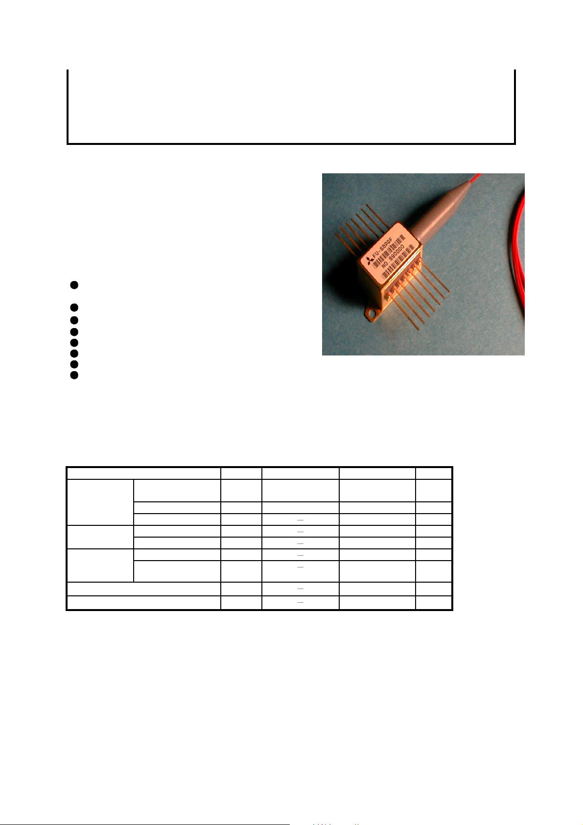
Module t ype FU-68PDF-V520MxxB is a 1.55mm DF B LD module with polarization maintaining optical fiber.
This module is suitable to a CW light source for
external modulator for use in 2.5Gb/s and 10Gb/s
digital optical communication systems.
This module is prepared in accordance with ITU-T
recommendation wavelength channel plan for D enseWDM transmission.
FEATURES
Multi quantum wells (MQW) DFB Laser Diode
module
Input impedance is 25W
Emission wavelength is in 1.55mm band
Polarization maintaining optical fiber pig-tail
Built-in optical isolator
Built-in thermal electric cooler
Butterfly package
With photodiode for optical output monitor
MITSUBISHI (OPTICAL DEVICES)
APPLICATION
High speed transmission systems (~10Gb/s)
Dense-WDM systems
ABSOLUTE MAXIMUM RATINGS (Tld=Tset)
Parameter Symbol Conditions Rating Unit
Laser diode
electric cooler
(Note)
Operating case temperature Tc -20 ~ 70
Storage temperature Tstg -40 ~ 85
Note) Even if the thermo-electric cooler (TEC) is operated within the rated conditions, uncontrolled current loading
or operation without heatsink may easily damage the module by exceeding the storage temperature range.
Thermistor resistance should be properly monitored by the feedback circuit during TEC operation to avoid
the catastrophic damage.
Optical output
power
Forward current If CW 150 mA
Reverse voltage Vrl
Reverse voltage Vrd 20 VPhotodiode
Forward current Ifd
Cooler current Ipe 1.3 AThermoCooler voltage Vpe
Pf CW 24 mW
2V
2mA
3.1 V
°C
°C
MITSUBISHI (OPTICAL DEVICES)
FU-68PDF-V520MxxB
1.55 mm DFB-LD MODULE WITH POLARIZATION MAINTAINING FIBER PIGTAIL
(WAVELENGTH SELECTED, BIAS CIRCUIT INTEGRATED, DIGITAL APPLICATION)
ELECTRICAL/OPTICAL CHARACTERISTICS (Tld=Tset, Tc=25°C unless otherwise noted)
Parameter Symbol Test Conditions Limits Unit
Min. Typ. Max.
Threshold current Ith CW - 10 25 mA
Operating current Iop CW, Pf=20mW - - 130 mA
Operating voltage Vop CW, Pf=20mW - - 2 V
Input impedance Zin Pf=20mW - 25 -
Light-emission central
wavelength
Central wavelength drift with
case temp.
Laser operating temperature Tset - 15 - 35 °C
Spectral line width
Side mode suppression ratio Sr CW, Pf=20mW 33 40 - dB
Cutoff frequency
(-1.5dB optical)
Polarization extinction ratio Ex CW, Pf=20mW 20 25 - dB
Relative intensity noise Nr CW, Pf=20mW,
Tracking error
(Note 2)
Differential efficiency
Monitor current Imon CW, Pf=20mW, Vrd=5V 0.2 - 4 mA
Dark current (PD) Id
Capacitance (PD) Ct Vrd=5V, f=1MHz - - 10 pF
Note 1) See Table 1.
Note 2) Er=max|10´log(Pf / Pf@25°C)|
lc
Dlc/DTc Tc=-20~70°C
Df
fc Pf=20mW 2 - - GHz
Er
h
CW, Pf=20mW (Note 1) nm
-1 - 0
CW, Pf=20mW - - 20 MHz
- -155 -145 dB/Hz
0.5~3GHz
Tc=-20~70°C,
APC, ATC
CW, Pf=20mW 0.15 - - mW/
Tc=25°C35--Optical isolation Iso
Tc=-20~70°C
Vrd=5V, Tc=-20~70°C
- - 0.5 dB
23 - -
- - 0.1
pm/°C
W
mA
dB
mA
 Loading...