

Mitsubishi Electric Corporation Semiconductor Group FU-645SDF-1M1B, FU-645PDF-W1M2C, FU-645PDF-W1M1B, FU-645PDF-V1M2C, FU-645PDF-V1M1B Datasheet
...
TZ7-01-111A (1/6)
May 25, 2001
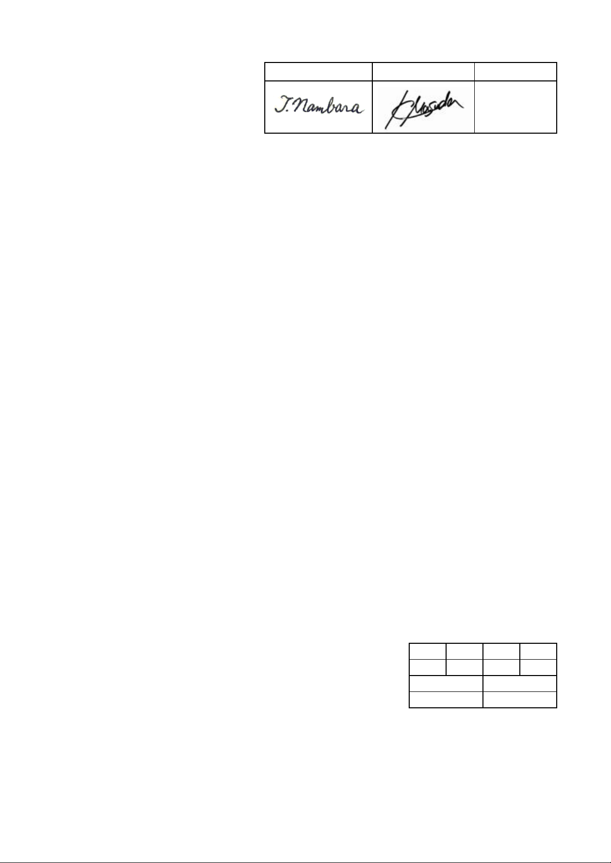
Approved Approved Charged
H.Koyanagi
Specification of uncooled DFB-LD module
Module type: FU-645SDF-x1Mxx
( Mitsubishi standard product )
A B C D
x
Date Approved
26.May.’01 T.Nambara
MITSUBISHI ELECTRIC CORPORATION
* Mitsubishi Electric Corp. reserves the right to change product design and specification without notice.
1.55 µm UNCOOLED DFB-LD MODULE WITH SINGLEMODE FIBER PIGTAIL
(BIAS CIRCUIT INTEGRATED, DIGITAL APPLICATION)
DESCRIPTION
Module type FU-645SDF-x1Mxx is a 1.55µm
Uncooled DFB-LD module with single-mode optical
fiber.
This module is suitable to a light source for use in
2.5Gb/s digital optical communication systems.
FEATURES
λ
l
/4 shifted Multi quantum wells (MQW) DFB
Laser Diode module
l Input impedance is 25
l Emission wavelength is in 1.55µm band
l High-speed response
l Built-in optical isolator
l Built-in thermistor and bias T
l 8-pin Mini-DIL package with Gull wing leads
l With photodiode for optical output monitor
Ω
TZ7-01-111A (2/6)
MITSUBISHI (OPTICAL DEVICES)
FU-645SDF-x1Mxx
APPLICATION
High speed transmission systems (~2.5Gb/s)
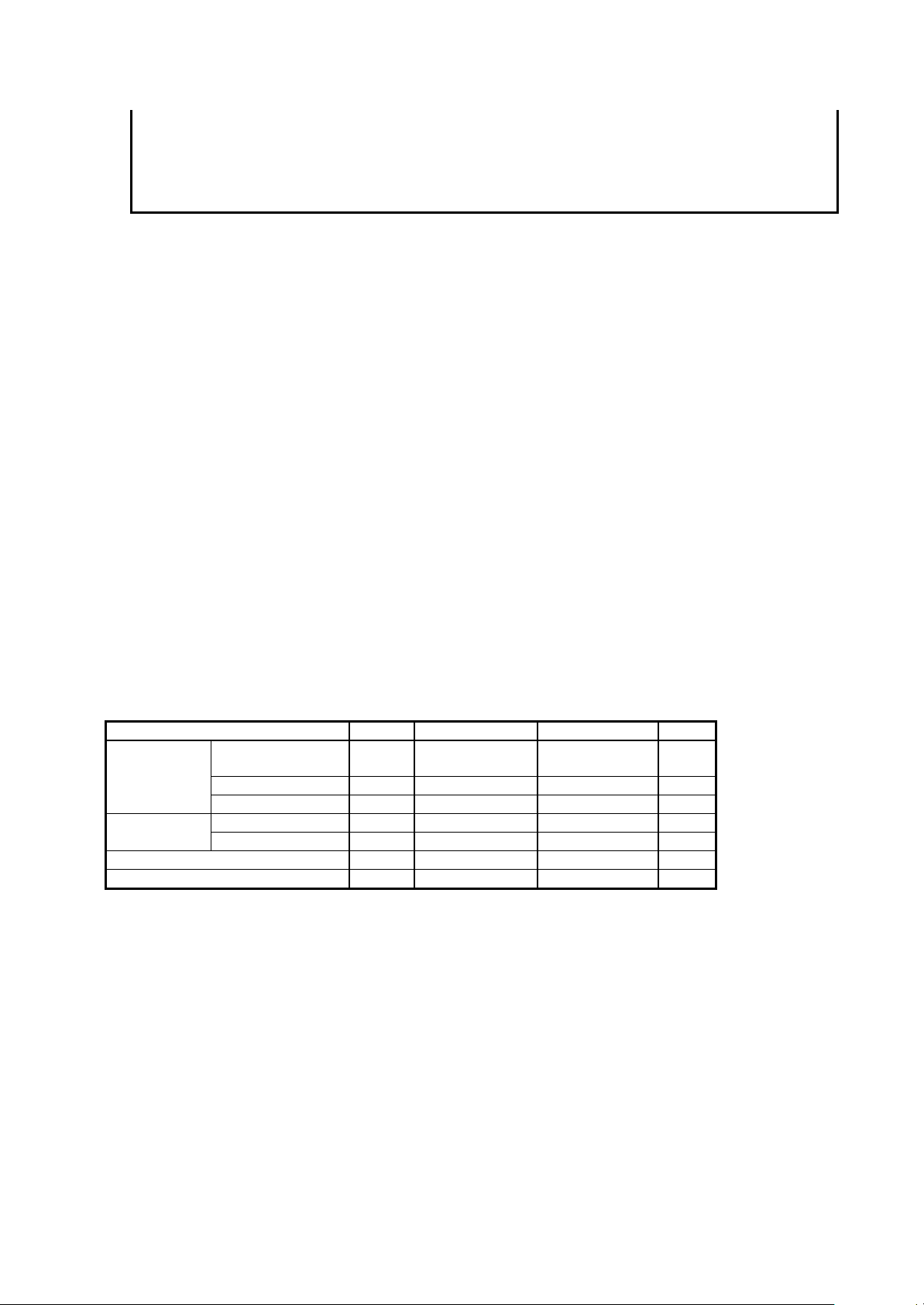
ABSOLUTE MAXIMUM RATINGS (Tc=25°C)
Parameter Symbol Conditions Rating Unit
Laser diode
Operating case temperature Tc - -5 ~ +70
Storage temperature Tstg - -40 ~ +85
Optical output
power
Forward current If CW 100 mA
Reverse voltage Vrl - 2 V
Reverse voltage Vrd - 20 VPhotodiode
Forward current Ifd - 2 mA
Pf CW 6 mW
°
C
°
C

TZ7-01-111A (3/6)
MITSUBISHI (OPTICAL DEVICES)
FU-645SDF-x1Mxx
1.55 µm UNCOOLED DFB-LD MODULE WITH SINGLEMODE FIBER PIGTAIL
(BIAS CIRCUIT INTEGRATED, DIGITAL APPLICATION)
ELECTRICAL/OPTICAL CHARACTERISTICS (Tc=-5~70°C, unless otherwise noted)
LimitsParameter Symbol Test Conditions
Min. Typ. Max.
CW, Tc=25°C - 10 25Threshold current Ith
CW 2 - 40
Optical output power
at threshold current
Input impedance Zin - - 25 Optical output power from
fiber end
Light-emission central
wavelength
Wavelength temperature
coefficient
Spectral width
Side mode suppression ratio Sr (Note1) 30 45 - dB
Cutoff frequency
(-1.5dB optical)
Rise and fall time (10~90%) tr, tf (Note1) - 125 150 psec
Dispersion penalty Pp (Note1), +1800ps/nm disp. - - 2 dB
Relative intensity noise Nr CW, Pf=1mW, f=1GHz - -150 -140 dB/Hz
Tracking error (Note 2) Er CW, APC(Imon=const.) - 0.5 1.25 dB
Monitor current Imon CW, Pf=1mW, Vrd=5V 0.05 - 1 mA
Optical isolation Iso - 20 - - dB
Dark current (PD) Id Vrd=5V - - 0.1
Capacitance (PD) Ct Vrd=5V, f=1MHz - - 10 pF
Thermistor resistance Rth Tc=25°C 9.5 10 10.5 k
B constant of Rth B - - 3950 - K
Note 1) 2.48832Gb/s NRZ, 223-1, Pf_ave=1mW, Extinction ratio 10dB, optical return loss from the line should be
greater than 24dB in order to ensure the specified performance.
Note 2) Er=max|10×log(Pf / Pf@25°C)|
Pth CW, Ibias=Ith - - 50
CW, Pf=2mW , Tc=25°C - 40 70Operating current Iop
CW, Pf=2mW , Tc=70°C - 60 90
CW, Pf=2mW , Tc=25°C - 1.2 1.5Operating voltage Vop
CW, Pf=2mW , Tc=70°C - 1.6 1.8
Pf CW, nominal - 2 - mW
λ
c CW, Pf=1mW 1530 1550 1570 nm
λ
ct - - 0.10 0.12 nm/°C
∆λ
fc Pf=1mW 3.5 - - GHz
η
(Note1), -20dB - - 0.4 nm
CW, Tc=25°C 0.06 - 0.1Differential efficiency
CW 0.036 - 0.15
Unit
mA
µ
W
mA
V
Ω
mW/
mA
µ
A
Ω
FIBER PIGTAIL SPECIFICATIONS
Parameter Limits Unit
Type SM Mode field diameter 10±1
Cladding diameter 125±2
Secondary coating outer diameter 0.9±0.1 mm
Connector See Table 1. Optical return loss of connector 40 (min) dB
µ
m
µ
m

1.55 µm UNCOOLED DFB-LD MODULE WITH SINGLEMODE FIBER PIGTAIL
(BIAS CIRCUIT INTEGRATED, DIGITAL APPLICATION)
DOCUMENTATION
• Threshold current (Ith) at Tc=25, 70°C
• Operating current (Iop) at Tc=25, 70°C
• Operating voltage (Vop) at Tc=25°C
• Light-emission central wavelength (λc) at Tc=25°C
• Monitor current (Imon) at Tc=25°C
• Optical output power from fiber end (Pf)
Table 1.
Type number Connector type L (Note 3)
FU-645SDF-1M1B None (Note 4) FU-645PDF-V1M1B FC/PC 28.4
FU-645PDF-W1M1B SC/PC 34.5
FU-645SDF-1M2C None (Note 4) FU-645PDF-V1M2C FC/PC 28.4
FU-645PDF-W1M2C SC/PC 34.5
Note 3) ‘L’ is defined in OUTLINE DIAGRAMs.
Note 4) There are some cases where a connector for testing is shipped with the product.
Then the fiber length not including the connector is more than 1000mm.
TZ7-01-111A (4/6)
MITSUBISHI (OPTICAL DEVICES)
FU-645SDF-x1Mxx

TZ7-01-111A (5/6)
PIN
MITSUBISHI (OPTICAL DEVICES)
FU-645SDF-x1Mxx
1.55 µm UNCOOLED DFB-LD MODULE WITH SINGLEMODE FIBER PIGTAIL
(BIAS CIRCUIT INTEGRATED, DIGITAL APPLICATION)
(1)
(Unit : mm)
4 3 2 1
PD
LD
19Ω
8765
Pin No.
←
Thermistor
TOP VIEW
FU-645SDF -x1M1B
FUNCTION
1 THERMISTOR
2 THERMISTER
3 LD BIAS, CATHODE
4 PD CATHODE
5 PD ANODE
6 LD ANODE
7 LD RF, CATHODE
8 LD ANODE

TZ7-01-111A (6/6)
PIN
MITSUBISHI (OPTICAL DEVICES)
FU-645SDF-x1Mxx
1.55 µm UNCOOLED DFB-LD MODULE WITH SINGLEMODE FIBER PIGTAIL
(BIAS CIRCUIT INTEGRATED, DIGITAL APPLICATION)
(2)
(Unit : mm)
4 3 2 1
PD
LD
19Ω
8765
Pin No.
←
Thermistor
TOP VIEW
FU-645SDF -x1M2C
FUNCTION
1 THERMISTOR
2 THERMISTER
3 LD BIAS, CATHODE
4 PD CATHODE
5 PD ANODE
6 LD ANODE
7 LD RF, CATHODE
8 LD ANODE
 Loading...