

Mitsubishi Electric Corporation Semiconductor Group FU-632SEA-6M91A, FU-632SEA-6M89A, FU-632SEA-6M87A, FU-632SEA-6M85A, FU-632SEA-6M83A Datasheet
...
MITSUBISHI (OPTICAL DEVICES)
FU-632SEA-3MxxA/FU-632SEA-6MxxA
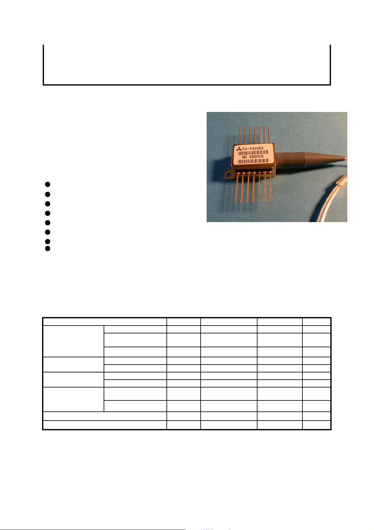
1.55 mm EAM/DFB-LD MODULE WITH SINGLEMODE FIBER PIGTAIL(WDM)
DESCRIPTION
Module type FU-632SEA-6MxxA is an electroaborption m odulator integrated w ith 1.55mm DF B-L D
module with single mode optical fiber.
This module is suitable to a light source in 2.5Gb/s
digital optical communication systems where the
distance is shorter than 640km.
This module is prepared in accordance with ITU-T
recommendation wavelength channel plan for D enseWDM transmission.
FEATURES
Input impedance is 50W
Integrated Electroabsorption Modulator(EAM)
Distributed feedback (DFB) Laser Diode
Emission wavelength is the 1.55mm band
Single-mode optical fiber pig-tail
Built-in optical isolator
Built-in thermal electric cooler
Butterfly package
APPLICATION
2.5Gbps,6400ps/nm WDM application
2.5Gbps,12800ps/nm WDM application
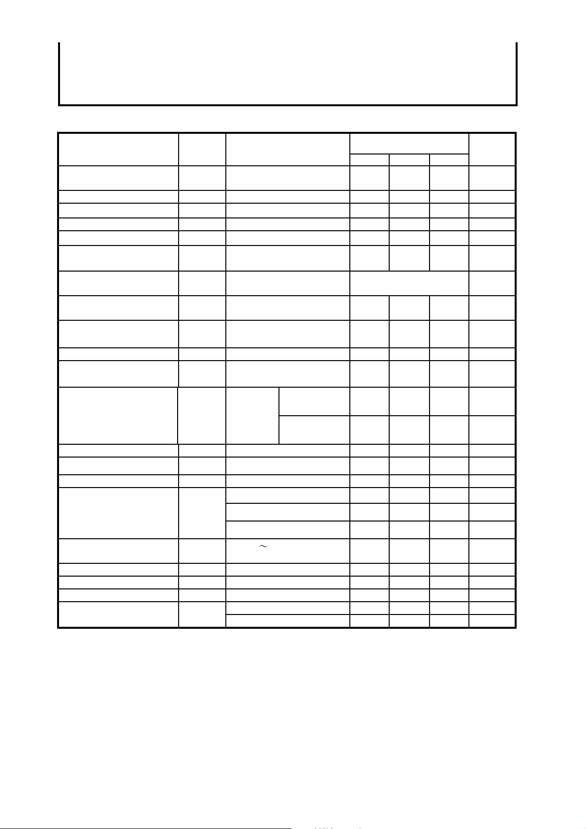
ABSOLUTE MAXIMUM RATINGS (Tld=Tset)
Parameter Symbol Conditions Rating Unit
Laser diode
monitoring
cooler(Note 1)
Operating case temperature Tc - -20 to 70
Storage temperature Tstg - -40 to 85
Note 1. Even if the thermoelectric cooler(TEC) is operated within the rated conditions, uncontrolled current
loading or operation without heat sink may easily damage the module by exceeding the storage
temperature range. Thermistor resist ance should be properly monitored by the feedback circuit during
TEC operation to avoid the catastrophic damage.
Optical output power Pf CW 6 mW
Forward current If CW 200 mA
Reverse voltage Vrl CW 2 V
Reverse voltage Vrm - 5 VModulator
Forward voltage Vfm - 1 V
Reverse voltage Vrd - 20 VPhotodiode for
Forward current Ifd - 2 mA
Current Ipe - 1.5 AThermoelectric
Voltage Vpe - 3 V
°C
°C
MITSUBISHI (OPTICAL DEVICES)
FU-632SEA-3MxxA/FU-632SEA-6MxxA
1.55 mm EAM/DFB-LD MODULE WITH SINGLEMODE FIBER PIGTAIL(WDM)
ELECTRICAL/OPTICAL CHARACTERISTICS (Tld=Tset, Tc=25°C unless otherwise noted)
Parameter Symbol Test Conditions Limits Unit
Min. Typ. Max.
Laser operating
Temperature
Threshold current Ith CW,Vm=0V 5 - 30 mA
Operating current Iop CW,Vm=0V 50 60 100 mA
Operating voltage Vop CW,Vm=0V,If=Iop - - 1.7 V
Input impedance Zin If=Iop - 50 - W
Optical output power from
fiber end
Light emission central
spectral wavelength
Center wavelength drift with
case temperature
Side mode suppression
ratio
Spectral width Dl (Note3,5) - 3 10 MHz
Relative intensity noise RIN CW,Vm=0V,If=Iop,2.5GHz - -155 -140 dB/Hz
Tset CW, If=Iop 15 - 35 °C
Pf CW,Vm=0V,If=Iop 1.2 - - mW
lc CW,Vm=0V,If=Iop,
Tld=Tset
Dlc/DTc CW,Vm=0V,APC
Tld=Tset ,Tc=-20~70°C
Sr (Note3,5) 35 40 - dB
see Table 1. nm
-1 - 0 pm/°C
-3MxxA series
@6400ps/nm
-6MxxA series
@12800ps/nm
Extinction ratio Ex (Note3,5) 11 - - dB
Rise/Fall time tr/tf (Note3,5),10-90% - - 120 ps
Cutoff frequency fc If=Iop,Vm=-1V 3.5 - - GHz
RF return loss S11
Tracking error Er Tc=-20 70°C,APC,
Monitor current Imon CW,If=Iop,Vm=0V 0.05 - 1.0 mA
Dark current(PD) Id Vrd=5V,Tld=25°C - - 0.1 mA
Capacitance(PD) Ct Vrd=5V,Tld=25°C,f=1MHz - 10 - pF
Note 2. Vm is EAM bias level at CW condition, Vpp and Voff are EAM amplitude and EAM high level offset
voltage respectively at modulated condition.
3. 2.48832Gb/s,NRZ,PRBS2
4. 2.48832Gb/s,NRZ,PRBS2
for FU-632SEA-3MxxA series, or dispersion=12800ps/nm for FU-632SEA-6MxxA series.
5. Optical return loss of the connectors should be greater than 40dB in order to get specified performance.
6. Er=MAX|10´log(Pf(Tc)/Pf(25°C))|
23
23
If=Iop,Vm=-1V,0~2GHz 10 - - dB
If=Iop,Vm=-1V,2~3GHz 7 - - dB
If=Iop,Vm=-1V,3~5GHz 3 - - dB
ATC (Note6)
Tc=25°C35--dBOptical isolation Iso
Tc=-20~70°C23--dB
-1,If=Iop,Vpp=2.5V,Voff=-0.2V,Tld=Tset, Back to back.
-1,If=Iop,Vpp=2.5V,Voff=-0.2V,Tld=Tset, dispersion=6400ps/nm
- - 1.0 dBPower penalty Pp (Note4,5)
- - 1.0 dB
- 0.3 0.5 dB
 Loading...