


FT SERIES
FT5000 Handbook

APRICOT FT S
With up to four Pentium ®II Xeon™ processors
ERIES
FT5000 HANDBOOK

Intel and “Pentium®II Xeon” are registered trademarks of Intel Corporation.
Microsoft, MS-DOS, Windows®95, Windows®98 and Windows®NT are registered trademarks of Microsoft
Corporation in the US and other countries.
Other trademarks mentioned within this document and not listed above are the properties of their respective
owners.
Information contained in this document is subject to change without notice and does not represent a
commitment on the part of Apricot Computers Limited. Any software described in this manual is furnished
under a license agreement. The software may be used or copied only in accordance with the terms of this
agreement. It is against the law to copy any disk supplied for any purpose other than the purchaser’s
personal use.
No part of this manual may be reproduced or transmitted in any form or by any means electronic or
mechanical including photocopying and recording, for any purpose, without the express written permission
of the publishers.
Copyright © Apricot Computers Limited 1998. All rights reserved.
Published by:
Apricot Computers Limited
3500 Parkside
Birmingham Business Park
Birmingham, England
B37 7YS
http://www.mitsubishi-computers.com
Printed in the United Kingdom

CONTENTS
Safety and Regulatory notices
General i
Maintenance and Transporting ii
Standards and Legalities iii
Contents
Power connection
1 Introduction
Physical specifications 1/1
Feature summary 1/2
Environmental specification 1/2
Front controls and indicators 1/3
Back controls and features 1/4
Expanded side view 1/5
Peripherals 1/6
Power supply 1/6
System security 1/7
2 Working inside your system
Tools and supplies needed 2/1
Before you remove any cover 2/1
Warnings and cautions 2/1
iii
Access cover 2/2
Subchassis and electronics bay 2/3
Add-in boards 2/4
Installing a peripheral in a front bay 2/5
Fans 2/7
3 Exchanging SCSI drives
SCSI hard disk drives 3/1
Hot-swapping a SCSI hard drive 3/2
Drive cabling considerations 3/4
Drive cabling considerations 3/9
FT5000 HANDBOOK i

Contents
4 Power supplies
Tools and supplies needed 4/1
Before you remove any cover 4/1
Warnings and cautions 4/1
General specification 4/2
Power supply indicators 4/2
Replacing a power supply 4/3
5 Mainboard
Mainboard features 5/1
Connector and component locations 5/2
Jumpers 5/3
Before carrying out any work in the system 5/4
General procedure for all jumper settings 5/5
Processors 5/6
Voltage regulator modules 5/10
Memory 5/11
Removing the memory module 5/12
Removing and installing DIMMs 5/14
Replacing the backup battery 5/16
Add-in board slots 5/17
SCSI and IDE controllers 5/18
6 I/O addresses, interrupts etc.
System I/O addresses 6/1
Memory map 6/3
Interrupts 6/3
7 Configuration software and utilities
Utilities and hot keys 7/1
Power On Self Test (POST) 7/2
Using BIOS Setup 7/2
Setup menus 7/4
Using the system setup utility 7/13
Emergency management port console 7/22
FRU and SDR load utility 7/32
Upgrading the BIOS 7/35
Using the firmware update utility 7/38
ii FT5000 HANDBOOK

Installing video drivers 7/38
Using the SCSI utility 7/38
8 Problem solving
Initial system startup 8/1
After the system has been running correctly 8/2
Specific problems and corrective actions problems 8/4
Error and informational messages 8/7
POST error codes and messages 8/10
Appendix Rack mounting the FT5000
Safety guidelines A/1
Additional precautions for rack mounting A/2
Changing from pedestal to rack A/3
Prepare the slide assemblies A/4
Contents
Prepare the server A/5
Prepare the equipment rack A/7
Install the server in the rack A/9
Equipment log and configuration record
Two pages to note down important system information and configuration details.
FT5000 HANDBOOK iii

SAFETY AND REGULATORY NOTICES
General
Avoid personal injury
To avoid personal injury when unpacking the server, use a mechanical assist unit to lift it off the shipping pallet. The
minimum server configuration weighs 38 kg; the maximum weighs 45 kg.
Do not attempt to lift or move the server by the handles on the power supplies.
Use a hand-truck or other mechanical assist unit to move the server from one location to another, or to raise it into
position for rack mounting.
Electrical
The computer uses a safety ground and must be earthed.
The system unit AC power cord is its ‘disconnect device’. Ensure that the system unit is positioned close to the AC power
outlet and that the plug is easily accessible.
The power cord packed with the computer complies with the safety standards applicable in the country in which it is first
sold. Use only this power cord. Do not substitute a power cord from any other equipment.
To prevent fire and electric shock, do not expose any part of the computer to rain or moisture. Turn off the computer and
unplug all power cords before moving or cleaning the system unit, or removing the system unit top cover.
Battery
This product contains a lithium battery.
Do not use a metal or other conductive implement to remove the battery. If a short-circuit is made between its positive and
negative terminals the battery may explode.
Replace a discharged battery with one of the same type; another type may explode or ignite. Follow any instructions
contained in this handbook to replace the battery. Dispose of a discharged battery promptly and in accordance with the
battery manufacturer’s recommended instructions. Do not recharge, disassemble or incinerate the discharged battery. Keep
away from children.
Laser products
Any CD-ROM drive fitted in this system is classified as a CLASS 1 LASER PRODUCT according to IEC825 Radiation
Safety of Laser Products (Equipment Classification: Requirements and User's Guide). The CLASS 1 LASER PRODUCT label
is located on the underside of the system unit.
The CD-ROM drive contains a laser system which is harmful to the eyes if exposed. Do not attempt to disassemble the
CD-ROM drive; if a fault occurs, call an authorised maintainer.
Use the CD-ROM drive only as described in this manual. Failure to do so may result in exposure to hazardous radiation.
Anti-static precautions
WARNING
Static electricity can cause permanent damage to electronic components. You should be aware of this risk, and take
precautions against the discharge of static electricity into the computer.
The computer is at risk from static discharge while the top cover is off. This is because the electronic components of the
motherboard are exposed. Memory modules, expansion cards and replacement processors are examples of electrostatic
sensitive devices (ESSDs).
All work that involves removing the cover must be done in an area completely free of static electricity. We recommend
using a Special Handling Area (SHA) as defined by EN 100015-1: 1992. This means that working surfaces, floor coverings
and chairs must be connected to a common earth reference point, and you should wear an earthed wrist strap and anti-static
clothing. It is also a good idea to use an ionizer or humidifier to remove static from the air.
When installing any upgrade, be sure you understand what the installation procedure involves before you start. This will
enable you to plan your work, and so minimise the amount of time that sensitive components are exposed.
Do not remove the system unit cover, nor the anti-static bag or wrapping of any upgrade, until you need to.
Handle static-sensitive items with extreme care. Hold expansion cards and add-on components only by their edges,
avoiding their electrical contacts. Never touch the components or electrical contacts on the motherboard or on expansion
cards. In general, do not handle static-sensitive items unnecessarily.
Keep all conductive material, and food and drink, away from your work area and the open computer.
FT5000 HANDBOOK i

SAFETY & REGULATORY NOTICES
Thermalcote bonding compound
The thermal bonding compound used between the system processor and its heat sink can cause skin irritation and stain
clothing. Avoid prolonged or repeated contact with skin. Wash thoroughly with soap and water after handling. Avoid
contact with eyes and inhalation of fumes. Do not ingest.
Ergonomic
When positioning the system unit, monitor and keyboard, take into account any local or national regulations relating to
ergonomic requirements.
Maintenance
Switch off and disconnect all cables before attempting to clean the computer.
Do not use sprays, solvents or abrasives that might damage the system unit surface. Do not use cleaning fluids or sprays near
air vents, ports, or the diskette and CD-ROM drives.
Occasionally wipe the system unit with a soft, slightly damp, lint-free cloth.
Occasionally wipe over the air vents on the rear and sides of the system unit. Dust and fluff can block the vents and limit
the airflow.
Occasionally clean the diskette and CD-ROM drives using a proprietary head cleaner.
Occasionally wipe the monitor with a soft, slightly damp, lint-free cloth.
It is best to use anti-static glass cleaner on the monitor screen, but do not spray glass cleaner directly onto the screen; it
could run down inside the case and damage the circuitry.
Transporting
Use common sense when handling the computer; hard disks in particular can be damaged if the computer is dropped or
handled roughly. As a precaution, back up the contents of the hard disks to tape or diskettes before moving the computer.
Switch off and disconnect all cables before attempting to move the computer, particularly do not try to move the computer
while it is plugged into the AC power supply.
When lifting and carrying the computer, use the metal sides of the system unit and never attempt to lift the system unit
with a monitor still on top.
If you need to transport the computer any great distance, use the original packing materials.
If you are planning to use the computer in another country, it may not be suitable, check with your supplier, particularly on
the availability of the correct AC power cords.
NOTE
Any existing maintenance or warranty agreement may not be supportable in another country. The system may have to be returned
to the supplier.
ii FT5000 HANDBOOK

Legalities
E
N
L
125V
250V
This equipment complies with the relevant clauses of the following European Directives (and all subsequent amendments):
Low Voltage Directive 73/23/EEC
EMC Directive 89/336/EEC
Telecommunications Directive 91/263/EEC
CE Marking Directive 93/68/EEC
IMPORTANT
This system, when supplied, complies with the CE Marking Directive and its strict legal requirements. Use only parts tested
and approved by Mitsubishi Electric PC Division. All expansion cards, drives and peripherals should carry the CE mark.
Standards
Safety
This product complies with the European safety standard EN60950 which will, when applicable, include the national
deviations for the country in which it is sold.
Electro-magnetic Compatibility (EMC)
This product complies with the following European EMC standards:
Emissions EN50022 Class A
Immunity EN50082-1
This product also complies with the following International EMC standards:
VCCI Class A (Japan)
SAFETY & REGULATORY NOTICES
Notes
All interconnecting cables (for example, signal and communication cables) should be less than 2 metres in length. If cable
extensions are used, ensure adequate earth connections are provided and screened cables are used.
If any metal casework components are removed, during upgrade work for example, ensure that all metal parts are correctly
re-assembled and all internal and external screws are re-fitted and correctly tightened.
Power Connection
Typical AC plugs
250V
E
L N
250V
E
N L
BS1363A SHUCO NEMA 5-15P SRAF 1962/DB16/87 ASE 1011
U. K. Austria Belgium Taiwan Denmark Switzerland
Finland France Thailand
Italy Germany Japan
Sweden Norway USA
Holland Canada
Checking the AC power supply
When this product is delivered, it is ready for the commercial AC power supply generally available in the country in which
it is first sold. It has been set for the correct voltage range, and is supplied with an AC power cord and plug which comply
with the relevant safety standards.
Before using the product in a country other than that in which it was originally sold, you must check the voltage and
frequency of that country’s AC power supply, and the type of power cord required there. Check the power rating labels on
the rear of the computer’s system unit and its monitor to ensure that they are compatible with the AC power supply.
250V
L
N
E
FT5000 HANDBOOK iii

SAFETY & REGULATORY NOTICES
The computer can function within two alternative AC power supply ranges:
AC power supply (voltage and frequency)
100 - 120 Volt AC, 50 - 60 Hz
200 - 240 Volt AC, 50 - 60 Hz
The voltage setting of the monitor must always be the same as the voltage setting of the system unit. See the User’s Guide that
accompanies the monitor or consult your supplier to find out how to change the voltage setting.
CAUTION
It is imperative that the computer is set to the correct voltage range before use. If not, the machine may be irreparably
damaged.
Connecting to the AC power supply
IMPORTANT
Any peripheral equipment that requires an AC power cord must be earthed.
Use the following guidance to connect the components together. It is important that you take each step in the order
indicated.
1. Before connecting any components, ensure that the AC power supply is switched off or disconnected, and that the
system unit, the monitor, and any peripherals are turned off.
2. Connect the component signal cables to their respective ports on the system unit: keyboard, mouse, monitor, audio
(where appropriate) and any other peripherals.
Where appropriate, connect the computer to the network.
3. Connect the component power cords: system unit, monitor to system, plus any other peripherals to nearby, grounded
AC power outlets. (Never substitute a power cord from any other appliance). Then switch on or connect the AC
power supply.
4. Turn on the system unit first, then the monitor, then other peripherals.
WARNING
The Handbook contains procedures which require opening of the system unit. Ensure all cables (including modem and network
cables) are disconnected before the system unit is opened
Power Cable Connections - UK ONLY
This equipment is supplied with an AC power cord that has a non-removable moulded plug.
Always replace the fuse with one of the same type and rating which is BSI or ASTA approved to BS1362. Always refit the
fuse cover, never use the plug with the fuse cover omitted.
External Speakers (where supplied)
Always switch off or disconnect the AC supply before disconnecting any of the speaker leads, whether audio or power.
Disconnect the AC supply from the speaker power unit when not in use for any period of time.
To prevent the risk of electric shock, do not remove speaker covers.
Connecting the speaker power cord to any other cords or joining cords together can cause fire and risk of electric shock.
.
iv FT5000 HANDBOOK
1 SYSTEM INTRODUCTION
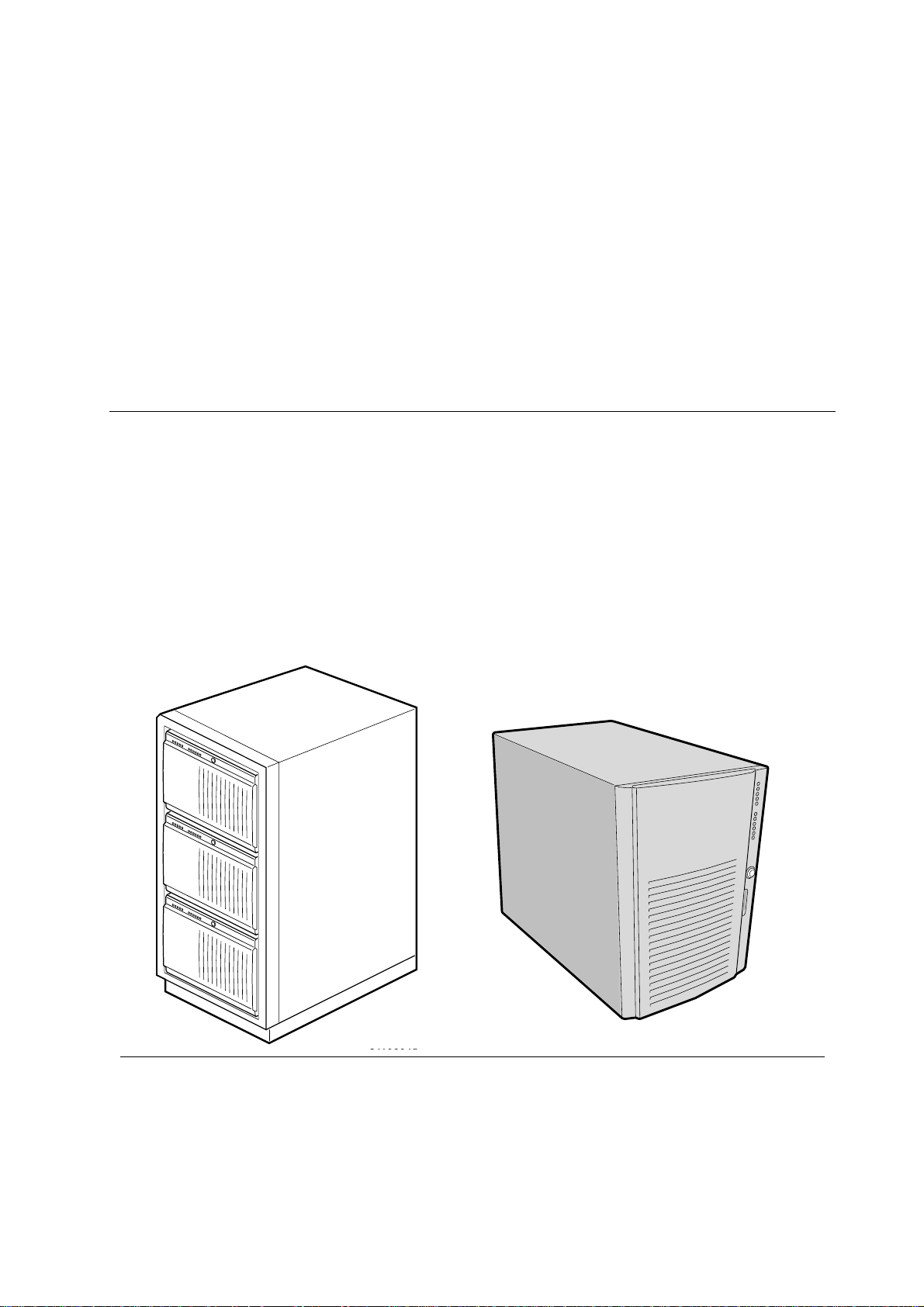
The FT5000 server is designed to either stand upright (pedestal mode) or be mounted in a rack
(rack mode). Figures below show examples of these configurations. Before operation, you must
configure the server for one of the two modes. (As standard the FT5000 is fitted with the pedestal
mountings, but a separate rack mounting kit is available).
If you require a rack mounting kit and have not already purchased one, contact your Mitsubishi
Electric supplier for details. For installation in an equipment rack, see the ‘FT5000 Rack
Mounting Guide’ booklet for full information.
Server physical specifications
Specification Pedestal Mode Rack Mode
Height 48.26 cm (19 inches) 7u
Width 31.12 cm (12.25 inches) 19 inch rack
Depth 63.5 cm (25 inches) 63.5 cm (25 inches)
Weight 38.25 kg minimum configuration
45 kg maximum configuration
Required front clearance 25 cm (inlet airflow <35 °C / 95 °F) 25 cm (inlet airflow <35 °C / 95 °F)
Required rear clearance 25 cm (no airflow restriction) 25 cm (no airflow restriction)
Required side clearance None, but side clearance required for service N/A
38.25 kg minimum configuration
45 kg maximum configuration
Typical rack with three servers Single server in pedestal mode
FT5000 HANDBOOK 1/1
OM08000

System introduction
Chassis feature summary
Feature Description
Controls All main system controls are behind a lockable front door which can be protected within
the system overall security ( see the information later in this chapter and in the
‘Configuration’ chapter).
All removable media drives, (Floppy diskette drive, CD-ROM drive etc.) are also behind
this door).
Drives Installed:
1.44 MB diskette drive, accessible from front subchassis.
Expansion capacity:
Two 5.25-inch-wide bays that are externally accessible, designed to hold halfheight standard removable media devices; the bays can be converted into a single
full-height bay.
Hard disk drives A front opening hard disk drive bay can accommodate up to 6 standard 3.5 inch single-
ended SCSI hard drives. They can be hot-swapped in the event of drive failure.
The whole drive bay can be padlocked to help prevent unauthorised access. The locked
door is then behind the system door which can be protected within the system overall
security (see the information later in this chapter and in the ‘Configuration’ chapter).
Expansion slot covers
Mainboard
Power supply
Cooling
Up to eight slot covers can be used; every slot opening that does not have an add-in board
installed must have a slot cover installed.
Form-factor, 40.5 cm 33 cm, ATX I/O.
Up to three 400-watt power supplies with integrated cooling fans and detachable AC
power cords.
Up to 11 fans provide cooling and airflow: three system fans inside the chassis (and three
more needed only for redundant cooling), one fan for each power supply (up to three),
and two fans for cooling hard drives.
Environmental specification
Temperature
Nonoperating
Operating
Humidity
Nonoperating
Operating wet bulb
Shock
Operating
Packaged
Acoustic noise < 47 dBA with one power supply at 28 °C +/- 2 °C
Electrostatic discharge (ESD)
AC Input Power
100 - 120 VAC
200 - 240 VAC
–40° to 70 °C
10° to 35 °C; derated 0.5 °C for every 305 m
Altitude to 3000m max; maximum rate of change = 10°C per hour
95% relative humidity (noncondensing) at 30 °C
Not to exceed 33 °C (with diskette drive or hard disk drive)
2.0 g, 11 msec, 1/2 sine
Operational after 30-inch free fall (cosmetic damage might occur)
< 50 dBA with two power supplies at 28 °C +/- 2 °C
< 55 dBA with three power supplies at 28 °C +/- 2 °C
Tested to 20 kilovolts (kV) per Intel environmental test specifications; no
component damage
100 - 120 VAC, 7.6 A, 50 - 60 Hz
200 - 240 VAC, 3.8 A, 50 - 60 Hz
1/2 FT5000 HANDBOOK

Chassis front controls and indicators
L
System introduction
ABC
D
E
F
G
H
I
J
K
A. External drive bays; CD-ROM drive shown installed
B. Diskette drive
C. Power On/Off button (holding down this button for more than four seconds causes a power-button
override to the PIIX4E when you release the button)
D. Sleep/Service button (holding down this button for LESS THAN four seconds enters sleep mode, which
requires an ACPI-compliant OS; holding it down for MORE THAN four seconds enters service mode,
which powers down the electronics bay but leaves hot-swap and peripheral bays running)
E. Reset button
F. Front panel LEDs (Top to bottom: top five are power on, disk bay power on, HDU activity, fan failure,
power supply failure; bottom six are hard-drive activity LEDs, labeled 0-5)
G. NMI button
H. System security lock
I. EMI shield lock
J. Internal drive bays
K. Metal EMI shield
L. Expansion drive bay
FT5000 HANDBOOK 1/3

System introduction
Chassis back controls and features
A
C
E
B
H
I
L
D
J
F
K
G
A. Parallel port
B. VGA monitor connector
C. Serial port A, COM1
D. Serial port B, COM2 (extended via ribbon cable from back panel to baseboard)
E. Mouse connector
F. Keyboard connector
G. Universal serial bus connector
H. Expansion slot covers (six slot connectors provided on baseboard)
I. Power supply bay
J. AC input power connector
K. Power supply fan
L. Power supply LED
M. Power supply failure LED (LED not lit means failure)
M
1/4 FT5000 HANDBOOK
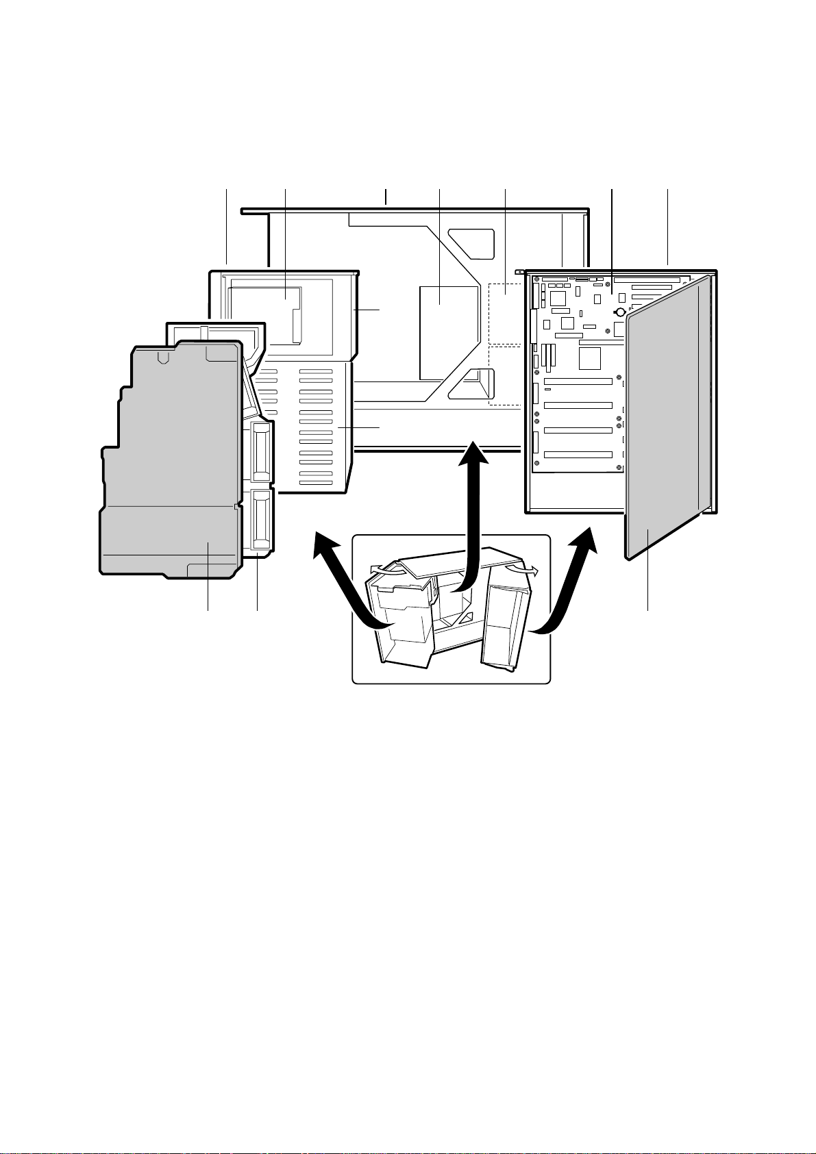
Expanded side view
System introduction
A
B
C
H
I
D
E F
G
A. Front swing-out subchassis
B. Diskette drive
C. Main chassis
D. Power backplane
E. Power supply(s)
F. Mainboard
G. Lift-out electronics bay
H. Removable media device bay
I. SCSI hard drive bay
J. Foam cover
K. Foam fan housing
L. Foam fan housing cover
JL K
FT5000 HANDBOOK 1/5

System introduction
Peripherals
3.5-inch diskette drive
The 3.5-inch diskette drive in the 3.5-inch peripheral bay supports 720 KB, and 1.44 MB media.
The drive is externally accessible from the front of the system.
Internal 3.5-inch hard drive bays
The chassis contains one bay for two 3.5-inch-wide (1" high or 1-5/8" high) LVDS SCSI hard
drives with internal cabling. An optional hot-swap-capable backplane can accommodate six
3.5-inch-wide (1" high) or three 3.5-inch (1-7/8" high) hard drives, which are accessed from the
lower front of the system.
As part of the hot-swap implementation, a drive carrier is required. The drives are mounted in the
carrier with four fasteners and the carrier snaps into the chassis. Carriers with heatsinks are
available for high-power drives that require extra cooling.
A single metal EMI shield and plastic door cover the drive bays. A hot-docking bay is provided for
drives that are 3.5 inches wide and 1 inch high. Drives can consume up to 22 watts of power and
must be specified to run at a maximum ambient temperature of 55 C.
The system was designed to allow the user to install a Redundant Array of Independent Disks
(RAID). A software implementation with onboard SCSI or an add-in board can be used to set up
RAID applications.
External bays for 5.25-inch removable media devices
The chassis has two 5.25-inch half-height bays that are accessible from the front of the system.
These bays are intended to provide space for tape backup or other removable devices.
You can convert the 5.25-inch bays to a single full-height bay. It is recommend that you do NOT
install hard drives in these bays as they cannot be properly cooled or shielded. A hard drive
generates EMI and is therefore more susceptible to damage in this location.
Power supplies
The chassis can be configured with one, two, or three 400-watt power supplies, each designed to
minimise EMI and RFI. Each supply operates within the following voltage ranges and is rated as
follows:
100 - 120 VAC at 50 - 60 Hz; 7.6 A maximum
200 - 240 VAC at 50 - 60 Hz; 3.8 A maximum
The DC output voltages of each power supply are as follows:
+3.3 V at 36 A max
+5 V at 24 A max (total combined output of +3.3 V and +5.5 V not to exceed 195 W)
+12 V at 18.0 A with 19.0 A <10ms peak
+24 V at 50mA
-12 V at 0.5 A
+5 V standby 1.5 A
Power is routed through the power cable to the 20-pin main connectors on the baseboard.
Remote sensing signals are provided through the cable to the 14-pin auxiliary connector on the
baseboard.
1/6 FT5000 HANDBOOK

System security
To help prevent unauthorised entry or use of the system, the system includes a three-position key
lock/switch to permit selected access to drive bays (position is communicated to BMC). The
system also includes server management software that monitors the chassis intrusion switch.
Mechanical locks and monitoring
The system includes a chassis intrusion switch. When the access cover is opened, the switch
transmits an alarm signal to the mainboard, where server management software processes the
signal. The system can be programmed to respond to an intrusion by powering down or by locking
the keyboard, (for example).
Software locks via the SSU or BIOS Setup
The SSU provides a number of security features to prevent unauthorised or accidental access to the
system. Once the security measures are enabled, access to the system is allowed only after the user
enters the correct password(s). For example, the SSU allows you to:
Enable the keyboard lockout timer so the server requires a password to reactivate the
keyboard and mouse after a specified time-out period of 1 to 120 minutes
Set and enable administrator and user passwords
System introduction
Set secure mode to prevent keyboard or mouse input and to prevent use of the front panel
reset and power switches
Activate a hot-key combination to enter secure mode quickly
Disable writing to the diskette drive when secure mode is set
Using passwords
If you set and enable a user password but not an administrator password, enter the user password
to boot the system and run the SSU.
If you set and enable both a user and an administrator password:
Enter either one to boot the server and enable the keyboard and mouse
Enter the administrator password to access the SSU or BIOS Setup to change the system
configuration
Secure mode
Configure and enable the secure boot mode by using the SSU. When secure mode is in effect, you:
Can boot the system and the OS will run, but you must enter the user password to use the
keyboard or mouse
Cannot turn off system power or reset the system from the front panel switches
Secure mode has no effect on functions enabled via the Server Manager Module or power control
via the real-time clock (RTC).
Taking the system out of secure mode does not change the state of system power. That is, if you
press and release the power switch while secure mode is in effect, the system will not power off
when secure mode is later removed. However, if the front panel power switch remains depressed
when secure mode is removed, the system will power off.
FT5000 HANDBOOK 1/7

System introduction
Software security features
Feature Description
Put the system into secure boot
mode
Disable writing to diskette In secure mode, the system will not boot from or write to a diskette unless a password is
Disable the power and reset
buttons
Set a time-out period so that
keyboard and mouse input are
not accepted
Also, screen can be blanked
and writes to diskette can be
inhibited
Control access to using the
SSU: set administrator
password
Control access to the system
other than SSU: set user
password
Boot without keyboard
Specify the boot sequence The sequence you specify in the ‘Boot device priority submenu’ (see the ‘Configuration’
How to enter secure mode:
Setting and enabling passwords automatically puts the system into secure mode.
If you set a hot-key combination (through the SSU or Setup), you can secure the system
simply by pressing the key combination. This means you do not have to wait for the
inactivity time-out period.
When the system is in secure mode:
The system can boot and run the OS, but mouse and keyboard input is not accepted until
the user password is entered.
At boot time, if a CD is detected in the CD-ROM drive or a diskette in drive A, the system
prompts for a password. When the password is entered, the system boots from CD or
diskette and disables the secure mode.
If you have not yet installed a CD-ROM drive, if there is no CD in the drive or diskette in
drive A, the system boots from drive C and automatically goes into secure mode. All
enabled secure mode features go into effect at boot time.
To leave secure mode:
Enter the correct password(s).
entered. To set these features, see the information given in the ‘Configuration’ chapter.
If this protection feature is enabled by the SSU, the power and reset buttons are disabled
when in secure mode.
You can specify and enable an inactivity time-out period of from 1 to 120 minutes. If no
keyboard or mouse action occurs for the specified period, attempted keyboard and mouse
input will not be accepted. To set this feature, see the information given in the
‘Configuration’ chapter.
If video blanking is enabled, the monitor display will go blank until the correct password(s)
is entered. To set this feature, see the information given in the ‘Configuration’ chapter.
To control access to setting or changing the system configuration, set an administrator
password and enable it through Setup or the SSU.
If both the administrator and user passwords are enabled, either can be used to boot the
system or enable the keyboard and/or mouse, but only the administrator password allows
changes to Setup and the SSU.
Once set, passwords can be disabled by setting the password to a null string or by changing
the Clear Password jumper. See the information given in the ‘Configuration’ chapter; or, to
change a jumper, see the information given in the ‘Mainboard’ chapter.
To control access to using the system, set a user password and enable Password on Boot
through Setup or the SSU.
Once set, passwords can be disabled by setting the password to a null string or by changing
the Clear Password jumper. See the information given in the ‘Configuration’ chapter; or, to
change a jumper, see, the information given in the ‘Mainboard’ chapter.
The system can boot with or without a keyboard. Before the system boots during POST,
BIOS automatically detects and tests the keyboard, if present, and displays a message. No
entry exists in the SSU for enabling or disabling a keyboard.
Do not plug in a keyboard while power is applied to the system.
chapter) determines the boot order. If secure mode is enabled (user password is set), you will
be prompted for a password before the system boots fully. If secure mode is enabled and the
‘Secure mode boot’ option is also enabled, (see ‘Security menu’ in the ‘Configuration’
chapter) the system boots fully but requires a password before accepting any keyboard or
mouse input.
1/8 FT5000 HANDBOOK

2 WORKING INSIDE THE SYSTEM
Tools and supplies needed
Phillips (cross-head) screwdriver (#1 and #2 bit).
Small flat-bladed screwdriver.
Jumper removal tool or needle-nosed pliers.
Antistatic wrist strap and conductive foam pad (recommended).
Pen or pencil.
Equipment log: as you integrate new parts into the system, add information about them
to your equipment log, at the back of the handbook. Record the model and serial number
of the system, all installed options, and any other pertinent information specific to the
system. You will need this information when running the SSU.
Safety: before you remove the access cover
Before removing the access cover at any time to work inside the system, observe these safety
guidelines.
1. Turn off and disconnect all peripheral devices connected to the system.
2. Turn off the system by using the push-button on/off power switch on the front of the system.
3. Unplug the AC power cords from the system or wall outlet.
4. Use full antistatic precautions as given in the Safety & Regulatory Notices at the front of this
handbook.
Warnings and cautions
These warnings and cautions apply whenever you remove the access cover of the system or remove
any components from it. Only an authorised engineer or other suitably qualified technical person
should attempt to integrate and configure the system.
System power on/off
system AC power. To remove power from system, you must unplug the AC power cords
from the wall outlet or the system.
Hazardous conditions, power supply
present inside the power supply. There are no user-serviceable parts inside it.
ESD and handling boards
sensitive to ESD. Hold boards only by their edges. Do not remove boards from their
protective wrapper until you are ready to put it straight into the system.
Cooling and airflow
before turning on the system. Operating it without the cover in place may damage system
components.
Avoid personal injury: To avoid personal injury when unpacking the server, use a
mechanical assist unit to lift it off the shipping pallet. The minimum server configuration
weighs 38 kg; the maximum weighs 45 kg.
: The on/off button on the front panel DOES NOT turn off the
: Hazardous voltage, current, and energy levels are
: Always handle boards carefully. They can be extremely
: For proper cooling and airflow, always install the chassis access cover
Do not attempt to lift or move the server by the handles on the power supplies.
Use a hand-truck or other mechanical assist unit to move the server from one location to
another, or to raise it into position for rack mounting.
FT5000 HANDBOOK 2/1

Working inside the system
Access cover
Removing the access cover
You need to remove the system access cover, and in some cases the front bezel, to reach
components inside the system. Facing the front of the system, the access cover is on the right side
for pedestal-mounted (tower) servers, and on the top for rack-mounted servers.
1. Observe the precautions as given in Safety & Regulatory Notices at the front of this
handbook.
1. Turn off and disconnect all peripheral devices connected to the system.
2. Turn off the system by using the power on/off switch on the front panel AND unplug all AC
power cords.
3. Remove and save the two screws from the back of the access cover; you will need them later
to reattach the cover.
4. Place the fingertips of your right hand under the built-in handle on the back of the cover. A
rounded, rectangular depression in the front middle of the access cover serves as another
handle.
5. Using an even pull, slide the cover backward, about 2 to 3cm, until it stops.
6. Pull the entire cover outward, straight away from the chassis, to disengage the rows of tabs
from the notches in the top and bottom edges of the chassis. Set the cover aside.
Installing the access cover
1. Before replacing the access cover, check that you have not left loose tools or parts inside the
system.
2. Check that cables, add-in boards, and other components are properly installed.
3. Position the cover over the chassis so that the rows of tabs align with slots in the chassis.
Slide the cover toward the front of the system until the tabs on the cover firmly engage in the
chassis.
4. Attach the cover to the chassis with the two screws you removed earlier, and tighten them
firmly.
5. Connect all external cables and the power cords to the system.
2/2 FT5000 HANDBOOK

Subchassis and electronics bay
The chassis is comprised of three parts: the main chassis, a swing-out subchassis at the front, and a
swing-out subchassis, called the electronics bay, at the rear. To access components in some
instances, you must swing away and/or completely remove the subchassis and electronics bay.
1. Observe the precautions as given in Safety & Regulatory Notices at the front of this
handbook.
2. Turn off and disconnect all peripheral devices connected to the system.
3. Turn off the system power by using the power on/off switch on the front panel AND unplug
all AC power cords.
4. Remove and save the two screws from the back of the access cover; you will need them later
to reattach the cover.
5. Remove the access cover.
6. Loosen screws on the top and bottom edges of the chassis (A) in the illustration below. These
screws attach the front subchassis and the electronics bay to the main chassis.
WWAARRNNIINNGG
You must disconnect all cabling to the electronics bay before rotating/removing the bay. Failure to
do so can result in serious damage to system components. The location of the main connectors in the
electronics bay is marked as D in the illustration below.
Working inside the system
7. Rotate the front subchassis left, away from the main chassis, until it stops (B).
8. Disconnect all cabling to the electronics bay (D).
9. Using the vertical edge of the electronics bay as a handle, rotate the bay right, away from the
main chassis, until it stops (C).
10. If necessary, completely remove the subchassis and electronics bay: rotate the bays outward
until the two pins that function as hinges for the bays slide out of their slots.
A
B
C
D
FT5000 HANDBOOK 2/3

Working inside the system
Add-in boards
Installing an add-in board
1. Remove access cover as detailed in the previous section.
2. Remove add-in board from its protective wrapper. Be careful not to touch the components or
gold edge connectors. Place board component-side up on an antistatic surface.
3. Record the serial number of the add-in board in your equipment log.
4. Set jumpers or switches according to the manufacturer’s instructions.
5. Remove and save the expansion slot cover from the chosen slot.
6. Hold the add-in board by its top edge or upper corners. Firmly press it into an expansion slot
on the baseboard. The tapered foot of the board retaining bracket must fit into the mating
slot in the expansion slot frame.
7. Slide the notch at the top of the retention bracket into its receptacle on the frame, which is
above and perpendicular to the top expansion slot.
8. Reinstall the access cover using the original screws.
B
A
C
A. ISA slot (USE HALF-LENGTH BOARD ONLY)
B. Six PCI slots (top to bottom in figure = PCI B3, B2, B1, B0, A3, and A2)
C. PCI slot A1
2/4 FT5000 HANDBOOK

Installing a 5.25-inch peripheral in the front bay
The system already has a CD-ROM drive installed, but you can add other devices, such as a tape
drive. It is recommend that you do NOT install hard drives in these bays as they cannot be
properly cooled or shielded. A hard drive generates EMI and is therefore more susceptible to
damage in this location.
CCAAUUTTIIOONNSS
Only single-ended SCSI devices supported: The internal SCSI interface in this system supports
only single-ended SCSI devices. Connecting differential SCSI drive types to this interface can result
in electrical damage to the baseboard and peripherals.
NNOOTTEESS
Save the filler panels and EMI shields: System EMI integrity and cooling are both protected by
having drives installed in the bays or filler panels and EMI shields covering the bays. When you
install a drive, save the panel and shield to reinstall in case you should later remove the drive and
not reinstall one in the same bay.
Bus termination when installing SCSI devices: It is important that your cabling and
connections meet the SCSI bus specification. Otherwise, the bus could be unreliable and
data corruption could occur or devices might not work at all. The SCSI bus needs to be
terminated at the end of the cable; this is usually provided by the last SCSI device on the
cable
Working inside the system
1. Observe the precautions as given in Safety & Regulatory Notices at the front of this
handbook.
2. Open the front bezel by rotating its right side out and to the left.
3. Push the tab (A) on the left side of the EMI metal shield to the right to disengage it from the
chassis. Save the shield.
A
4. Remove the drive from its protective wrapper, and place it on an antistatic surface.
FT5000 HANDBOOK 2/5

Working inside the system
5. Record the drive model and serial numbers in your equipment log at the rear of the
handbook.
6. Set any jumpers or switches on the drive according to the drive manufacturer’s instructions.
7. Using two screws of the appropriate size and length (not supplied), attach each plastic slide
rail with its metal grounding plate to the drive.
D
B
A
C
A. Tape drive or other removable media device
B. Tab on slide rail
C. Screws (4)
D. Slide rails (2)
8. Position the drive so the plastic slide rails engage in the bay guide rails. Push the drive into
the bay until the slide rails lock in place.
9. Connect a power cable to the drive. The connectors are keyed and can be inserted in only one
way.
10. Connect a signal cable to the drive. The connectors are keyed and can be inserted in only one
way.
SCSI drive: Attach connectors on the cable to the SCSI device or devices you are
installing.
IDE drive: The baseboard has one IDE connector.
11. Close the front bezel.
2/6 FT5000 HANDBOOK

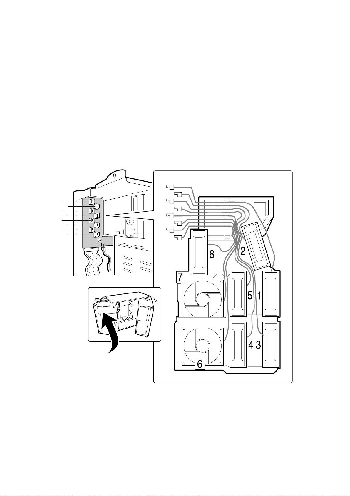
Fans
The FT5000 server contains five removable chassis fans (and can accept up to three more) to cool
the boards and removable media drives. These chassis fans connect to the front panel board and
are enclosed in a removable foam assembly. The integrated power supply fan(s) provides more
cooling and airflow.
Removing the system fan assembly
Working inside the system
1. Observe the precautions as given in Safety & Regulatory Notices at the front of this
handbook.
2. Remove the access cover as previously detailed.
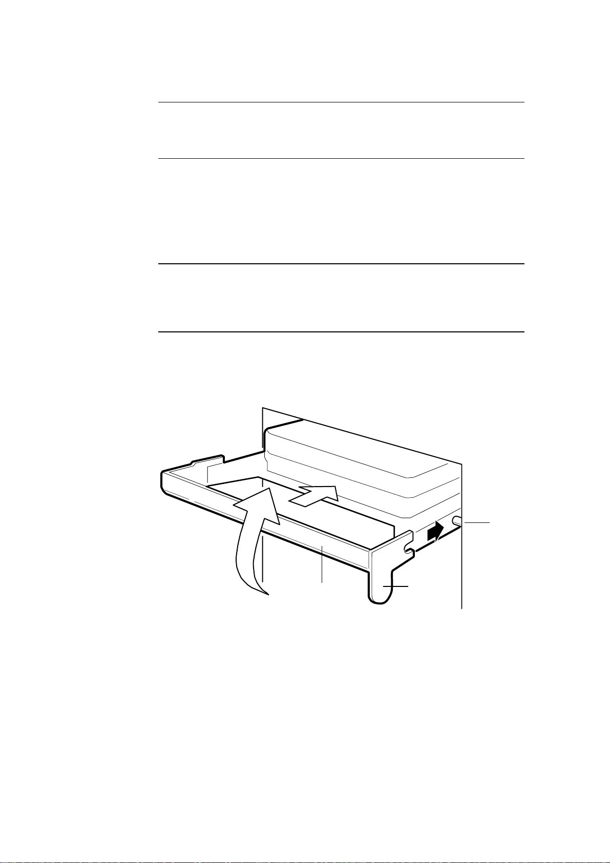
3. Remove the foam cover from the front subchassis by pulling it straight out as above. For
better access to the individual fan cables on the front panel board, carefully rotate the right
edge of the foam fan assembly outward into the opening where the foam cover was.
4. Label and disconnect the individual fan cables from the front panel board. For fan cabling
considerations, see page.
5. Remove the fan assembly from the chassis.
Removing an individual system fan
NNOOTTEE
Correct airflow direction: The side of each fan is embossed with directional arrows indicating
airflow direction. Always note the direction of the arrows on a fan before removing it. Contact
your Mitsubishi dealer for suitable replacement fans.
1. Observe the precautions as given in Safety & Regulatory Notices at the front of this
handbook.
2. Remove the access cover as previously detailed.
FT5000 HANDBOOK 2/7
Working inside the system
3. Remove the foam cover from the front subchassis by pulling it straight out as shown above.
Be careful not to break the foam.
4. For better access to the individual fan cables on the front panel board, carefully rotate the
right edge of the foam fan assembly outward into the opening where the foam cover was.
5. Label and disconnect the desired fan cable from the front panel board. Be sure to note the
position of the cable where it is held in place in the foam fan assembly.
6. Remove the fan cable from the foam assembly, being careful not to break the foam.
7. Remove the fan from the foam assembly. All systems fans sit differently in the assembly, but
in general, each fan can slide in and out of the foam in only one way.
The two installed fans nearest the 5.25-inch drive bays (fans 6 and 7 below) are separated by a
square piece of foam (the piece with a crescent-shaped hole) that extends perpendicularly from the
front of the fans, it is the rectangle between the round faces of fans 6 and 7). You must remove this
piece to access the two fans it separates (pull it straight out).
1
2
3
4
5
6
7
8
1
1
2
3
4
5
6
7
8
2/8 FT5000 HANDBOOK
3 EXCHANGING SCSI HARD DRIVES
SCSI hard disk drives
The system supports a variety of single-ended SCSI devices. As shipped, the system might
contain only one hard disk drive. Contact your Mitsubishi Electric dealer for a list of
approved and compatible single-ended SCSI devices.
WWAARRNNIINNGG
The single-ended SCSI backplane requires installing single-ended SCSI devices in your
system. Installing differential SCSI drive types can result in electrical damage to the
baseboard and the peripherals.
CCAAUUTTIIOONN
Electrostatic discharge (ESD) and ESD protection: ESD can damage disk drives, add-in
boards, and other components. This server can withstand normal levels of environmental
ESD while you are hot-swapping SCSI hard disk drives. However, we recommend doing all
procedures in this manual only at an ESD-protected workstation. If one is not available,
you can provide some ESD protection by wearing an antistatic wrist strap attached to
chassis ground of the server—an unpainted metal surface—when handling any components.
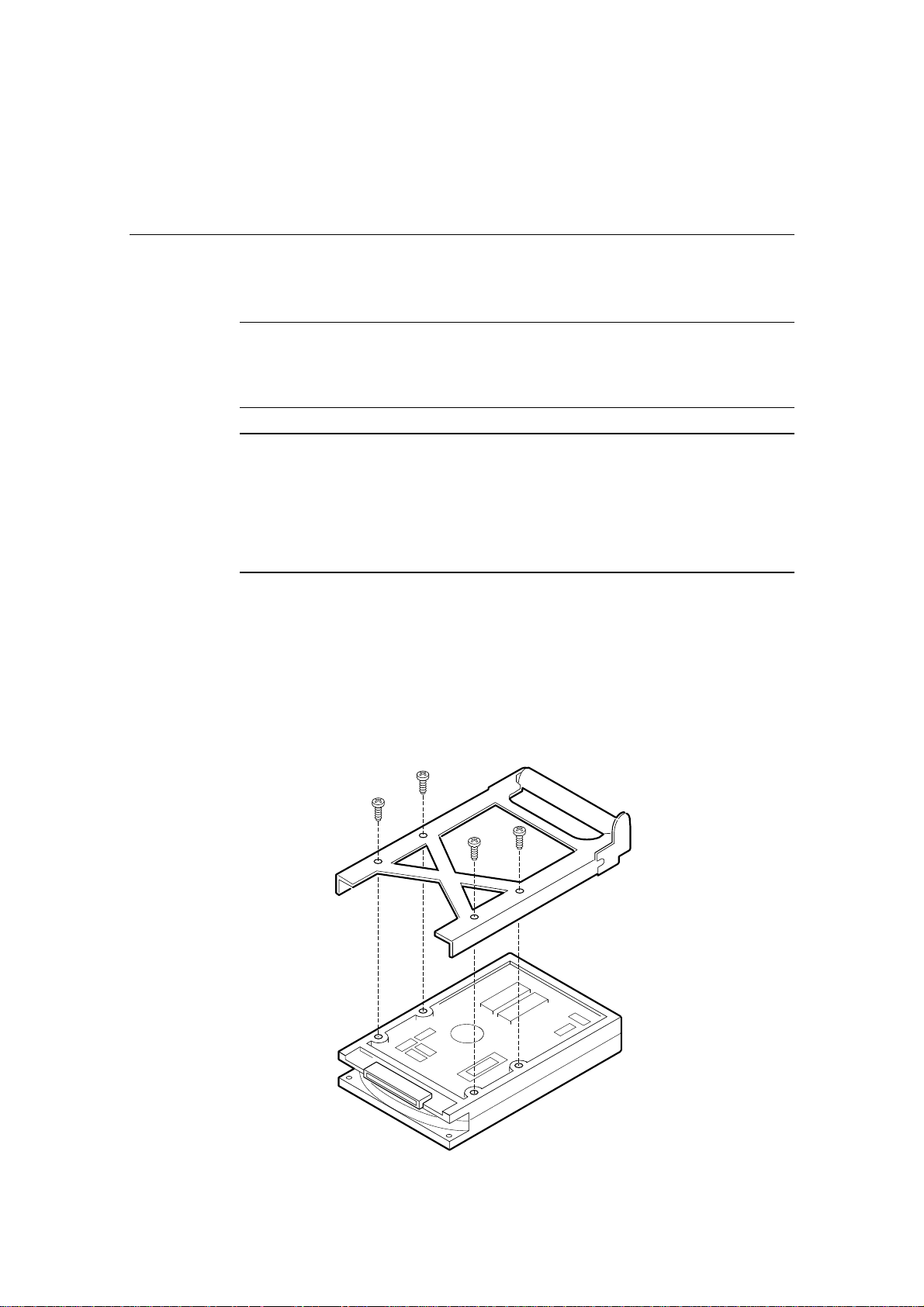
Mounting a SCSI hard disk drive in a plastic carrier
1. Remove the 3.5-inch hard drive from its wrapper and place it on an antistatic surface.
2. Record the drive model and serial number in your equipment log
3. Orient the drive so the connector is near the top surface of the drive, then place the
plastic carrier on top of the drive.
4. Using four screws of the correct size and length (not supplied), attach the carrier to
the drive.
FT5000 HANDBOOK 3/1

Exchanging SCSI hard drives
Hot-swapping a SCSI hard disk drive
CCAAUUTTIIOONN
It is vital that you remember the exact cable and connector arrangement of your hard disks,
particularly if you are using a RAID (Redundant Array of Independent Disks) configuration. If
you fail to restore the arrangement so that all cables, plugs and disks are as they were originally,
you risk losing all the data on your hard disks.
A bank of six yellow LEDs on the front panel monitors the drive status of each drive in the
upper and lower hot-docking bays. Each LED corresponds directly to a drive, so that the
upper-most LED reflects activity in the upper-most drive. The six LEDs and corresponding
drives are numbered (top to bottom) ‘zero’ to ‘five’. When a yellow LED is on
continuously, it is okay to hot-swap (replace) a bad drive with a good one. You DO NOT
need to shut the system down to hot-swap a drive.
1. Open the front bezel by rotating its right side out and to the left.
2. If you installed a padlock on the metal door to the bays, unlock the padlock and
remove it.
3. Loosen the plastic latch securing the metal door to the chassis, and open the door.
4. Check the bank of yellow LEDs on the front panel to determine which drive is bad.
5. Press the rounded tab on the right of the carrier to the left (toward the center of the
drive—(B) in illustration below, while gently pulling straight down on the carrier
handle (A). This disengages the latch that secures the carrier to the chassis.
6. Grasp the plastic carrier handle and pull it toward you to disengage the drive
connector from the backplane connector.
A
B
A. Carrier handle (pull straight down to disengage carrier and bay from backplane connector)
B. Tab on carrier handle (push left to unlock carrier)
7. Carefully slide the bad drive forward out of the bay. Place the drive on an antistatic
surface.
8. Position the new plastic carrier and drive assembly so that it engages the bay guide
rails.
3/2 FT5000 HANDBOOK
Exchanging SCSI hard drives
CCAAUUTTIIOONN
It may be wise to keep a separate written record in the log sheet, at the rear of this book, of
which trays are fitted with drives, along with their specification. Update this record with
any changes or additions.
9. Gently push the drive into the bay. To engage the latch, the carrier handle should be
approximately at a 45 angle from the vertical front of the chassis. As you push the
drive into the bay, the two rounded notches in the carrier handle (B) in illustration
below, slide onto the two round pegs inside the drive bay (A). When they engage,
push the handle straight up (C) to lock the notches onto the pegs and press the
rounded tab on the right of the carrier to the left until it clears the edge of the bay and
snaps into place.
NNOOTTEE
Since the hard disk drives for your Mitsubishi server are exclusively SCSI drives, it is
important to note that the SCSI connector on the backplane of the drive module contains
the device address. This means that, for a given connector, any disk drive that is fitted to
that connector will have the same SCSI address.
10. Close the metal door, and secure it to the chassis with the plastic latch.
11. For security and to prevent unauthorised access to the bays, insert a padlock through
the metal loop protruding through the door.
12. Close the front bezel.
A
C
A. Round peg inside drive bay
B. Round notches on carrier handle (must fit over pegs in drive bay)
C. Carrier handle
B
FT5000 HANDBOOK 3/3

Exchanging SCSI hard drives
Drive cabling considerations
This section summarises device cabling requirements and constraints. The number of
devices you can install depends on:
The number supported by the bus
The number of physical drive bays available
The height of drives in the internal bays (1-inch or 1.6-inch high)
The combination of SCSI and IDE devices
SCSI Requirements
One narrow and two wide SCSI cables are standard in the system.
All SCSI devices must be unterminated except the peripheral at the end of the SCSI cable.
Hard drives usually provide an active termination, while CD-ROM drives do not. Because
we recommend putting hard drives only in the internal bays, this means that you should
route the SCSI cable so that the last device on the cable is a hard drive in the internal bay.
3/4 FT5000 HANDBOOK
 Loading...