

FT2200
System Guide
NATIONAL
ACCREDITATION
OF CERTIFICATION
BODIES

FT2200
System Guide

Intel is a registered trademark of Intel Corporation.
Pentium Pro is a trademark of Intel Corporation.
Other brand and product names are trademarks and/or registered trademarks of their
respective holders.
Information contained in this document is subject to change without notice and does not
represent a commitment on the part of Apricot Computers Limited. The software
described in this manual is furnished under a license agreement. The software may be
used or copied only in accordance with the terms of this agreement.
It is against the law to copy any disk supplied for any other purpose than the purchaser’s
personal use.
All rights reserved; no use or disclosure without written consent.
Copyright © 1996
Published by:
Apricot Computers Limited
3500 Parkside
Birmingham Business Park
B37 7YS
http://www.apricot.co.uk
Printed in the United Kingdom
Part no. 15760431 Rev 01
ii

IMPORTANT SAFETY
INSTRUCTIONS
1. Read these instructions carefully. Save these instructions for
future reference.
2. Follow all warnings and instructions marked on the product.
3. Unplug this product from the wall outlet before cleaning. Do not
use liquid cleaners or aerosol cleaners. Use a damp cloth for
cleaning.
4. Do not use this product near water.
5. Do not place this product on an unstable cart, stand, or table.
The product may fall, causing serious damage to the product.
6. Slots and openings in the cabinet and the back or bottom are
provided for ventilation; to ensure reliable operation of the
product and to protect it from overheating, these openings must
not be blocked or covered. The openings should never be
blocked by placing the product on a bed, sofa, rug, or other
similar surface. This product should never be placed near or over
a radiator or heat register, or in a built-in installation unless
proper ventilation is provided.
7. This product should be operated from the type of power indicated
on the marking label. If you are not sure of the type of power
available, consult your dealer or local power company.
8. This product is equipped with a 3-wire grounding-type plug, a
plug having a third (grounding) pin. This plug will only fit into a
grounding-type power outlet. This is a safety feature. If you are
unable to insert the plug into the outlet, contact your electrician to
replace your obsolete outlet. Do not defeat the purpose of the
grounding-type plug.
iii

9. Do not allow anything to rest on the power cord. Do not locate
this product where persons will walk on the cord.
10. If an extension cord is used with this product, make sure that the
total ampere rating of the equipment plugged into the extension
cord does not exceed the extension cord ampere rating. Also,
make sure that the total rating of all products plugged into the
wall outlet does not exceed 15 amperes.
11. Never push objects of any kind into this product through cabinet
slots as they may touch dangerous voltage points or short out
parts that could result in a fire or electric shock. Never spill liquid
of any kind on the product.
12. Do not attempt to service this product yourself, as opening or
removing covers may expose you to dangerous voltage points or
other risks. Refer all servicing to qualified service personnel.
13. Unplug this product from the wall outlet and refer servicing to
qualified service personnel under the following conditions:
a. When the power cord or plug is damaged or frayed
b. If liquid has been spilled into the product
c. If the product has been exposed to rain or water
d. If the product does not operate normally when the operating
instructions are followed. Adjust only those controls that are
covered by the operating instructions since improper
adjustment of other controls may result in damage and will
often require extensive work by a qualified technician to
restore the product to normal condition.
e. If the product has been dropped or the cabinet has been
damaged
f. If the product exhibits a distinct change in performance,
indicating a need for service
iv

14. Use only the proper type of power supply cord set (provided in
your keyboard/manual accessories box) for this unit. It should be
a detachable type: UL listed/CSA certified, type SVT/SJT, rated
6A 125V minimum, VDE approved or its equivalent. Maximum
length is 15 feet (4.6 meters).
15. The computer uses a safety ground and must be earthed.
The system unit AC power cord is its ‘disconnect device’. Ensure
that the system unit is positioned close to the AC power outlet
and that the plug is easily accessible. The power cord packed
with the computer complies with the safety standards applicable
in the country in which it is first sold. Use only this power cord. Do
not substitute a power cord from any other equipment.
To prevent fire and electric shock, do not expose any part of the
computer to rain or moisture and turn off the computer and
unplug all power cords before moving or cleaning the system unit,
or removing the system top cover.
16. Any CD-ROM drive fitted in this system is classified as a CLASS
1 LASER PRODUCT according to IEC825 Radiation Safety of
Laser Products (Equipment Classification: Requirements and
User's Guide). The CLASS 1 LASER PRODUCT label is located
on the rear of the system unit.
It will be in high visibility colours and bear the details shown
above.
Use the CD-ROM drive only as described in this manual. Failure
to do so may result in exposure to hazardous radiation.
17. When positioning the system unit, monitor and keyboard, take
into account any local or national regulations relating to
ergonomic requirements.
v

18. This product complies with the European safety standard
EN60950 and when applicable, will include the national
deviations for the country in which it is sold.
19. This product complies with the following European EMC
standards:
Emissions EN55022 Class A
Immunity EN50082 Level 1
This product also complies with the following International EMC
standards:
VCCI level 1 (Japan)
The applicable standards for the country of sale will be shown on
the label fixed to the rear of the system.
20. All interconnecting cables (e.g. Microphone, headphone and
speaker) and communication cables should be less than 2
metres in length. If cable extensions are used, ensure adequate
earth connections are provided and screened cables are used.
21. This equipment complies with the relevant clauses of following
European Directives:
Low voltage Directive 73/23/EEC
EMC Directive 89/336/EEC
CE marking Directive 93/668/EEC
Caution: This system has been tested to comply with CE marking
and its strict legal requirements. Use only Apricot tested and
approved parts. Failure to do so may result in invalidating both
the compliance and your warranty. All expansion cards must
carry CE approvals.
vi

22. Power connection information
Typical AC plugs:
250V
E
L N
250V
E
N L
125V
N
E
L
BS1363A SHUCO NEMA 5-15P
United Kingdom Austria Belgium Taiwan
Finland France Thailand
Germany Holland USA
Italy Norway Canada
Sweden
Procedure:
Note: Any ancillary equipment using an AC power supply cable
should be earthed.
The power supplies in the computer and the monitor are correct
for the country in which the system is first sold. Do not alter any
switch settings on the rear of the system. If you wish to use the
computer in another country it may not be suitable, contact your
supplier or an authorised Apricot dealer.
• Before connecting up any parts of the system, ensure that
the AC supply is switched off or disconnected.
• First connect up the keyboard, mouse, monitor signal cable,
and audio cables as appropriate.
vii

• Connect up all AC cables. (System to supply, system to
monitor, all related peripherals.) Then switch on or connect
the AC supply.
• Switch on the monitor first, then the computer followed by
the peripherals, such as printer or speakers.
• If the monitor AC lead is connected to the computer AC
outlet, when you come to switch off, the computer
power button will switch off the monitor at the same
time.
23. Power Cable Connections - UK ONLY
This equipment is supplied with an AC power lead that has a non-
removable moulded plug.
Always replace the fuse with one of the same type and rating
which is BSA or ASTA approved to BS1362. Always refit the fuse
cover, never use the plug with the fuse cover omitted.
24. German Acoustic Noise Regulation: Sound power level is less
than 70 dB(A) according to DIN 45635 Part 19 (ISO 7779).
Die Deutsche Akoustische Lärm-Regulierung: Der Grad der
Klangstärke ist weniger als 70 dB (A) je nach DIN 45635 Teil 19
(ISO 7779).
viii

About this Manual
Purpose
This system guide aims to give you all the necessary information to
enable you to set up and operate the system.
Manual Structure
This system guide consists of five chapters.
Chapter 1 System Introduction
This chapter generally describes the system’s unique features
and powerful architecture. It includes a brief introduction of the
new generation Intel Pentium Pro CPU that forms the heart of
the system.
Chapter 2 Setting Up the System
This chapter helps you get started. It illustrates how to prepare
the system for installation, connect the cables, and startup the
system.
Chapter 3 System Configuration
This chapter describes the six major system components that
include the system housing, system board, memory board, front
panel board, disk-array backplane boards, and power supply.
Chapter 4 BIOS Utility
This chapter explains the BIOS parameter functions. It tells
how to configure the system by setting the parameters.
Chapter 5 Diagnostics and Utilities
This chapter describes how to use the EISA Configuration
Utility.
ix
Conventions
The following are the conventions used in this manual:
Text entered by user
Screen messages
a, e, s
, etc. Represent the actual keys that you
Represents text input by the user.
Denotes actual messages that
appear onscreen.
have to press on the keyboard.
NOTE
Gives bits and pieces of additional
information related to the current
topic.
WARNING
Alerts you to any damage that
might result from doing or not doing
specific actions.
CAUTION
Gives precautionary measures to
avoid possible hardware or
software problems.
IMPORTANT
Reminds you to do specific actions
relevant to the accomplishment of
procedures.
TIP
Tells how to accomplish a
procedure with minimum steps
through little shortcuts.
x

Table of Contents
Chapter 1 System Introduction
1.1 Features.....................................................................1-1
1.1.1 Intel Pentium Pro Microprocessor...............1-1
1.1.2 System Architecture....................................1-3
1.1.3 SCSI Disk Array..........................................1-5
1.2 External Configuration................................................1-6
1.2.1 Front Panel..................................................1-6
1.2.2 Rear Panel..................................................1-8
Chapter 2 Setting Up the System
2.1 Pre-installation Requirements....................................2-1
2.1.1 Selecting a Site...........................................2-1
2.1.2 Checking the Package Contents.................2-2
2.1.3 Transporting the System.............................2-3
2.1.4 Positioning the System Unit........................2-4
2.2 Basic Connections.....................................................2-6
2.2.1 Keyboard.....................................................2-6
2.2.2 Mouse.........................................................2-7
2.2.3 VGA Monitor................................................2-8
2.2.4 Printer..........................................................2-9
2.2.5 Power Cables............................................2-10
2.3 System Startup.........................................................2-11
2.3.1 Turning On the System Power..................2-11
2.4 Power-on Problems..................................................2-13
xi

Chapter 3 System Configuration
3.1 System Housing........................................................ 3-1
3.1.1 Internal Structure........................................ 3-2
3.1.2 Opening the Housing Panels...................... 3-3
3.1.3 ESD Precautions........................................ 3-6
3.1.4 Installing External Devices......................... 3-6
3.1.5 Installing a Hot-swappable SCSI Drive.....3-11
3.1.6 Installing an Expansion Board.................. 3-16
3.2 System Board.......................................................... 3-18
3.2.1 Layout....................................................... 3-18
3.2.2 Jumpers and Connectors......................... 3-19
3.2.3 Installing a Pentium Pro CPU................... 3-24
3.3 Memory Board......................................................... 3-26
3.3.1 Layout....................................................... 3-26
3.3.2 Rules for Adding Memory......................... 3-26
3.3.3 Memory Configurations............................ 3-27
3.3.4 Installing a SIMM...................................... 3-28
3.3.5 Removing a SIMM.................................... 3-29
3.3.6 Installing the Memory Board..................... 3-30
3.3.7 Reconfiguring the System........................ 3-32
3.4 SCSI Disk Array Backplane Board.......................... 3-33
3.4.1 Features................................................... 3-33
3.4.2 Layout....................................................... 3-34
3.4.3 Jumper Settings ....................................... 3-35
3.4.4 SCSI Hard Disk ID Feature...................... 3-36
3.4.5 Channel Configuration.............................. 3-37
xii

Chapter 4 BIOS Utility
4.1 Entering Setup...........................................................4-2
4.2 Basic System Configuration.......................................4-3
4.2.1 Date and Time.............................................4-4
4.2.2 Diskette Drives............................................4-5
4.2.3 Hard Disk Drives.........................................4-6
4.2.4 System Memory..........................................4-7
4.2.5 Math Coprocessor.......................................4-7
4.2.6 Video Display..............................................4-8
4.2.7 Communication Settings.............................4-8
4.2.8 Enhanced IDE Features..............................4-9
4.2.9 Num Lock After Boot...................................4-9
4.2.10 Memory Test.............................................4-10
4.2.11 Auto Configuration Mode ..........................4-10
4.2.12 Fast Boot Mode.........................................4-10
4.3 Advanced System Configuration..............................4-11
4.3.1 Shadow RAM............................................4-12
4.3.2 L1 and L2 Cache (CPU Cache) ................4-12
4.3.3 Memory at 15MB-16MB............................4-13
4.4 System Security Setup.............................................4-14
4.4.1 Disk Drive Control.....................................4-14
4.4.2 Onboard Communication Ports.................4-16
4.4.3 Onboard PS/2 Mouse (IRQ12)..................4-18
4.4.4 Setup Password........................................4-19
4.4.5 Power On Password .................................4-20
xiii

4.5 PCI System Configuration....................................... 4-21
4.5.1 PCI IRQ Setting........................................ 4-21
4.5.2 VGA Palette Snoop.................................. 4-22
4.5.3 Onboard SCSI.......................................... 4-22
4.6 Non-PnP ISA Card Configuration............................ 4-23
4.6.1 IRQ/DMA.................................................. 4-25
4.6.2 Expansion ROM Region........................... 4-25
4.6.3 I/O Region................................................ 4-25
4.6.4 Local Memory Region .............................. 4-25
4.7 Load Setup Default Settings.................................... 4-26
4.8 Leaving Setup......................................................... 4-27
Chapter 5 Diagnostics and Utilities
5.1 EISA Configuration Utility v3.0.................................. 5-1
5.1.1 Functions.................................................... 5-1
5.1.2 Making Menu Selections............................ 5-2
5.1.3 Getting Help ............................................... 5-3
5.1.4 Program Menus.......................................... 5-4
5.1.5 Configuring Your Computer for the
First Time ................................................... 5-6
5.1.6 Adding or Removing Boards .................... 5-10
5.1.7 Viewing or Editing Configuration Details.. 5-12
5.2 Remote Diagnostic Management............................ 5-15
xiv

List of Figures
1-1 Pentium Pro CPU Architecture...................................1-2
1-2 System Architecture ...................................................1-3
1-3 Front Panel.................................................................1-6
1-4 Rear Panel..................................................................1-8
2-1 Transporting the System ............................................2-3
2-2 Feet Positioning for a Standalone System .................2-4
2-3 Feet Positioning for a System Standing Against a
Wall............................................................................2-5
2-4 Connecting a Keyboard..............................................2-6
2-5 Connecting a Mouse...................................................2-7
2-6 Connecting a VGA Monitor.........................................2-8
2-7 Connecting a Printer...................................................2-9
2-8 Power Cables...........................................................2-10
2-9 Opening the Upper Front Panel................................2-11
2-10 System Power On.....................................................2-12
3-1 System Housing .........................................................3-1
3-2 System Internal Components.....................................3-2
3-3 Opening the Upper Front Panel..................................3-3
3-4 Opening the Lower Front Panel..................................3-4
3-5 Opening the Left Panel...............................................3-5
3-6 Removing the Upper Front Panel...............................3-7
3-7 Attaching a 3.5-inch Diskette Drive on the Frame......3-8
3-8 Installing a 3.5-inch Diskette Drive.............................3-8
xv

List of Figures (continued)
3-9 Attaching the Metal Guides to a CD-ROM Drive ....... 3-9
3-10 Installing a 5.25-inch External Device...................... 3-10
3-11 Unlocking the Drive Tray Switch.............................. 3-11
3-12 Pulling Out a Hot-swap Drive Tray.......................... 3-12
3-13 Connecting the Drive Cables (Wide SCSI Drive)..... 3-13
3-14 Connecting the Drive Cables
(Narrow SCSI Drive)................................................ 3-13
3-15 Installing a Hot-swap Drive Tray.............................. 3-14
3-16 Locking the Drive Tray Switch................................. 3-15
3-17 Removing a Bracket Cover...................................... 3-16
3-18 Installing an Expansion Board................................. 3-17
3-19 System Board Layout.............................................. 3-18
3-20 Jumper and Connector Locations............................ 3-19
3-21 VRM Settings for CPU1 (3.3V for 200 MHz)............ 3-21
3-22 VRM Settings for CPU2 (3.3V for 200 MHz)............ 3-21
3-23 Clock Frequency Ratio Setting (CN15).................... 3-23
3-24 Attaching the Heat Sink to the CPU......................... 3-24
3-25 Installing a Pentium Pro CPU.................................. 3-25
3-26 Memory Board Layout............................................. 3-26
3-27 Installing a SIMM..................................................... 3-28
3-28 Removing a SIMM................................................... 3-29
3-29 Inserting the Memory Board.................................... 3-30
3-30 Attaching the Board Holding Clamp......................... 3-31
3-31 SCSI Disk Array Backplane Board.......................... 3-34
3-32 Jumper Settings....................................................... 3-35
xvi

List of Figures (continued)
3-33 Single-Channel Configuration...................................3-37
3-34 Dual-Channel Configuration.....................................3-39
5-1 ECU Main Menu.........................................................5-3
5-2 Steps in Configuring Your Computer..........................5-4
5-3 Maintain Configuration Diskette..................................5-5
5-4 Important EISA Configuration Information..................5-6
5-5 Examine Switches or Print Report..............................5-7
5-6 Save and Exit .............................................................5-9
5-7 Add or Remove Boards............................................5-11
5-8 View or Edit Details ..................................................5-13
List of Tables
1-1 LED Indicator Description...........................................1-7
3-1 Jumper Settings........................................................3-20
3-2 Voltage Identification Codes.....................................3-22
3-3 Connector Functions ................................................3-23
3-4 Memory Configurations ............................................3-27
3-5 SCSI ID Settings.......................................................3-36
4-1 Drive Control Settings...............................................4-15
4-2 Serial Port 1 Settings................................................4-16
4-3 Serial Port 2 Settings................................................4-16
4-4 Parallel Port Settings................................................4-17
4-5 Parallel Port Operation Mode Settings.....................4-18
5-1 Keyboard Function Keys ............................................5-2
xvii

xviii

&& KK DSDSWWHUHU
System Introduction
1.1 Features
This powerful 64-bit dual-processor system is loaded with a host of
new and innovative features. It offers a new standard for flexible
productivity ideal for local area networks and multiuser server
environments.
1.1.1 Intel Pentium Pro Microprocessor
The Intel Pentium Pro CPU is the heart of the system. Designed to
work with the Orion chipset composed of a PCI bridge and memory
controller, the Pentium Pro running at up to 200 MHz carries a new
generation of power not present in its predecessors.
The system board has two CPU sockets to accommodate up to two
Intel Pentium Pro CPUs for a dual-processor configuration. This
configuration doubles efficiency and reliability thereby upgrading
overall system performance. The Pentium Pro supports a wide range
of applications running under operating systems such as DOS,
Windows, WindowsNT, OS/2, UNIX, and NetWare.
The CPU also incorporates the first-level (L1) and second-level (L2)
caches, the advanced peripheral interrupt controller (APIC), and the
system bus controller. Figure 1-1 shows the CPU architecture.
System Introduction 1-1
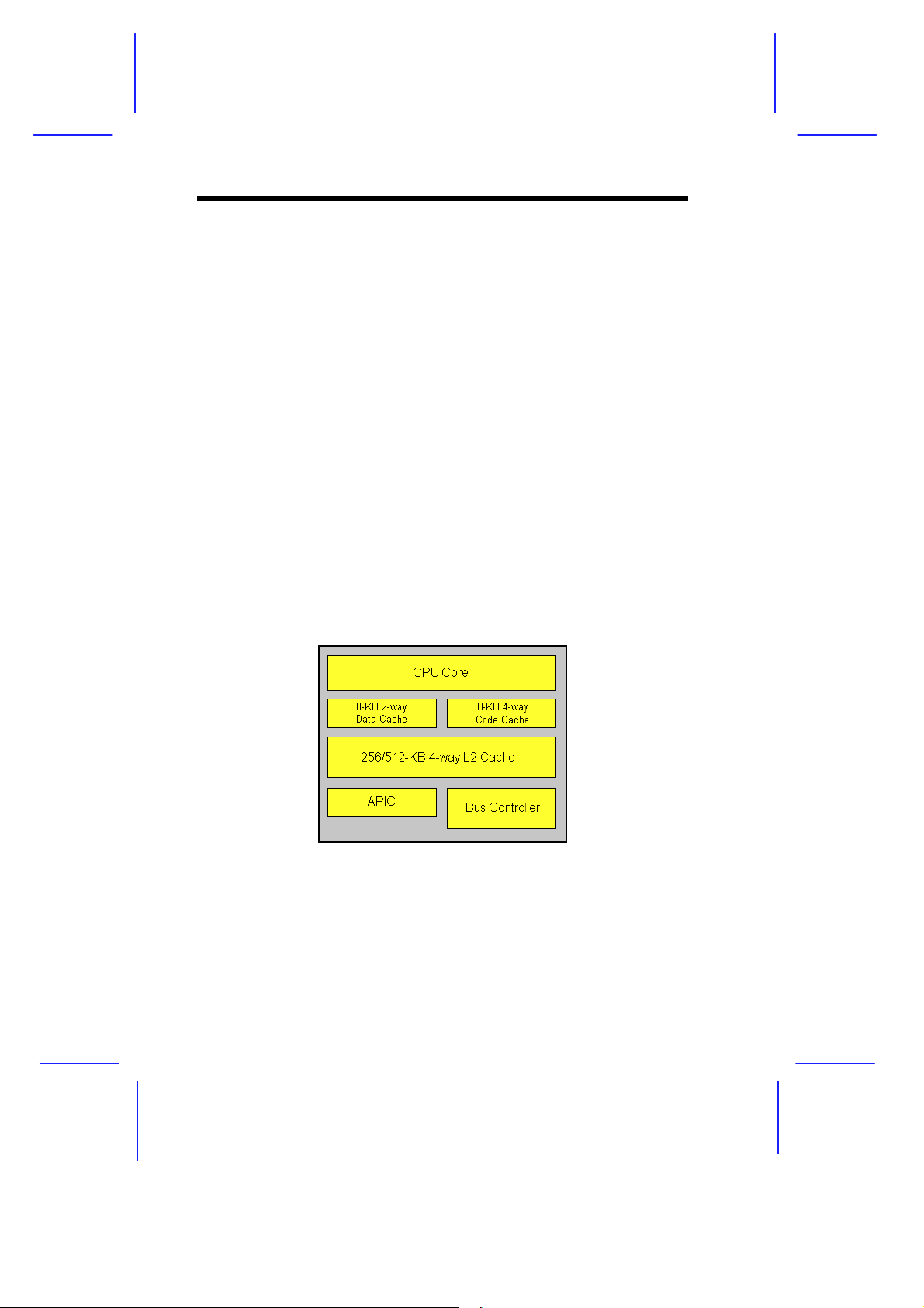
First-level and Second-level Cache
The Pentium Pro has a 16-KB first-level and 256/512-KB second-level
cache. These caches produce a high hit rate that reduces the
processor’s external memory bandwidth requirements.
Advanced Peripheral Interrupt Controller (APIC)
The APIC unit inside the CPU along with the I/O APIC unit facilitate
multiprocessor interrupt management. The APIC works with multiple
I/O subsystems where each subsystem have its own interrupts that
help minimize centralized system overhead.
Bus Controller
The bus controller integrated in the Pentium Pro CPU controls the
system bus to make it perform its functions efficiently. It ensures that
the bus serves as a reliable interconnection between one or two
CPUs, I/O bridge, and memory controllers.
Pentium Pro CPU Architecture
Figure 1-1 Pentium Pro CPU Architecture
1-2 System Guide
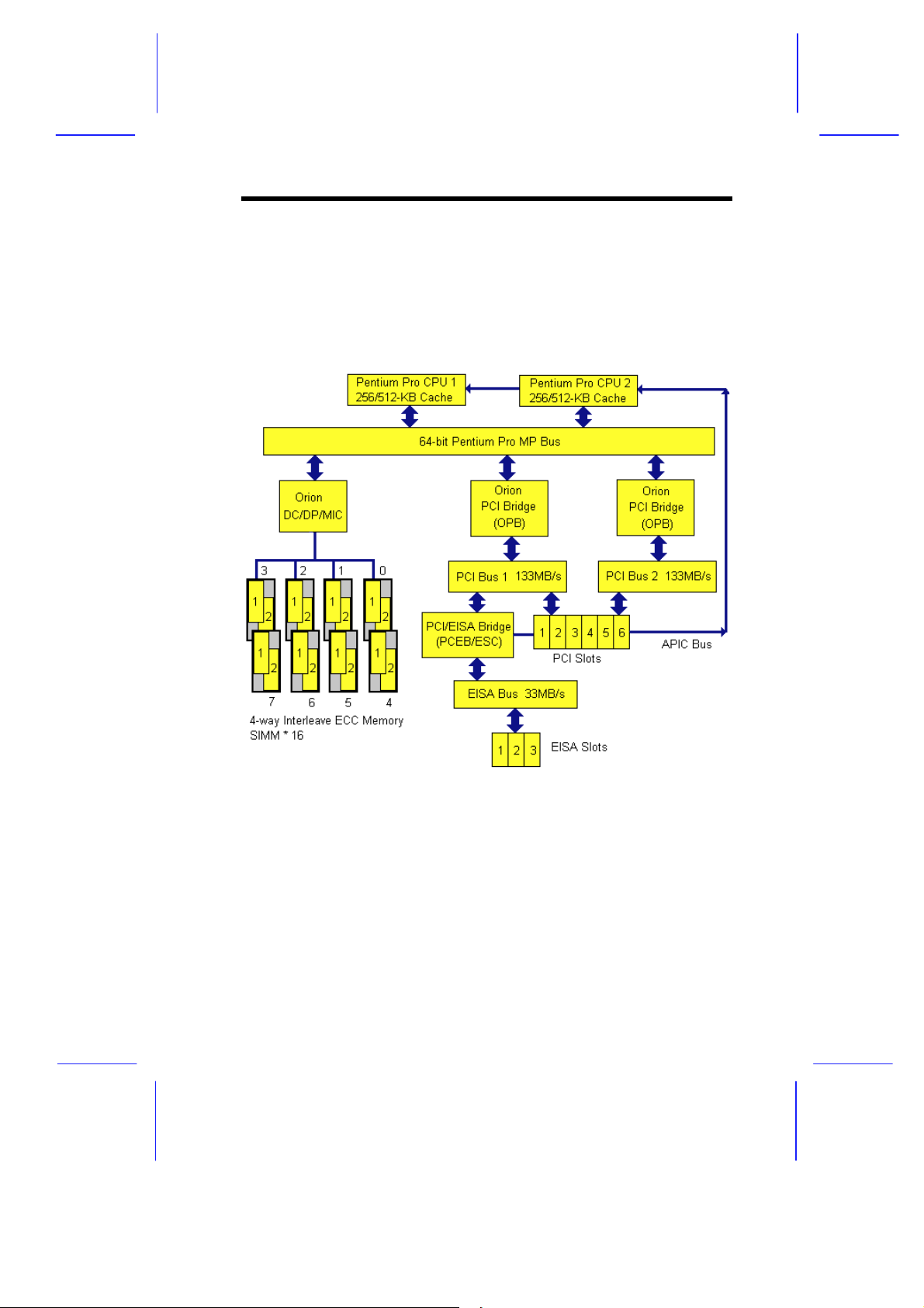
1.1.2 System Architecture
The system bus, PCI buses, EISA bus, Orion PCI bridge (OPB), Orion
memory controller (OMC), PCI/EISA Bridge (PCEB), and EISA system
controller (ESC) comprise the basic system architecture.
Figure 1-2 System Architecture
System Introduction 1-3

System Bus
The system bus is the CPU’s major connection to all the system
devices, primarily the PCI and EISA bridges, and the memory
controllers. It can handle as many as eight outstanding transactions
at a time through the transaction pipelining feature in which
consecutive tasks from the CPU are queued in and transported to the
designated devices on a first-in first-out basis. Pipelining allows for
transaction overlapping in different phases as the CPU does not have
to wait for each transaction to complete before it issues the next
transaction. This produces significant improvement on overall system
performance.
The bus architecture supports a number of features that ensure high
reliability. It has an 8-bit error correction code (ECC) that protects the
data lines and a 2-bit parity code that protects the address lines.
The bus uses the gunning transceiver logic (GTL+), a synchronous
latched bus protocol that simplifies timing constraints. This protocol
supports higher frequency system designs but requires a low voltage
that reduces electromagnetic interference (EMI) resulting to a lower
power consumption.
PCI and EISA Buses
The system supports two PCI buses created by the two PCI bridge
chipsets (OPB). The PCI buses serve as the links between the PCI
bridges and the PCI devices onboard.
The EISA bus connects the EISA devices to the other system devices
through the PCI/EISA bridge (PCEB) and the EISA system
controller (ESC). The use of the PCEB and ESC maintains
compatibility with the EISA environment.
1-4 System Guide

Orion PCI Bridge
The Orion PCI bridge (OPB) is a low-cost I/O subsystem solution for
high-performance systems. The OPB translates transactions between
the system bus and the PCI buses using 32-byte buffers for inbound
and outbound postings. The use of two OPBs in the system creates
an architecture that allows faster data transfers.
Orion Memory Controller
The Orion memory controller (OMC) acts as an interface between the
system bus and the system memory. It consists of the DRAM
control (DC) chip and the data path (DP) chip. The OMC relates to
the DRAM array through four memory interface controller (MIC) chips.
The OMC supports 256-bit 4-way memory interleaving resulting to a
more efficient memory traffic management.
1.1.3 SCSI Disk Array
The system supports an array of eight hot-swappable disk drive trays
through an 8-slot SCSI backplane board. The trays accommodate
wide and narrow SCSI hard disks. With the AIC-7880 SCSI controller
onboard, the transfer rate reaches up to 40 MB per second for ultra
SCSI and 20 MB per second for wide SCSI.
System Introduction 1-5
1.2 External Configuration
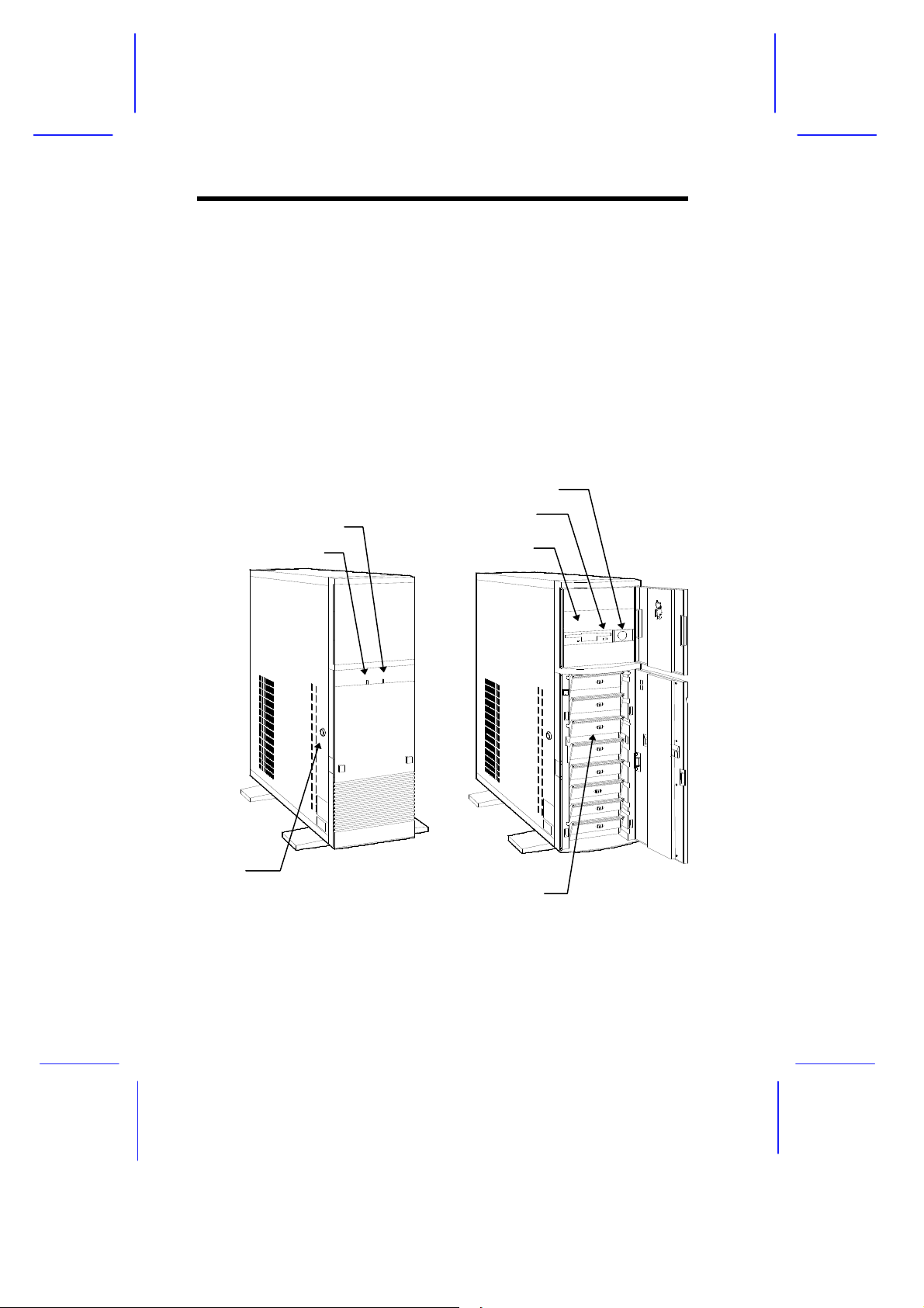
1.2.1 Front Panel
The system front panel is divided into two sections. The upper front
panel consists of the diskette/CD-ROM/tape drive bays, power switch,
LED indicators, and an embedded reset switch.
The lower part contains the externally accessible hard disk drive bays
with eight drive trays for narrow or wide SCSI disk drives. (The basic
system may only have a 3.5-inch diskette drive and a CD-ROM drive
and no SCSI hard disks installed.)
Power Switch
Power LED
Hard Disk Drive LED
3.5-inch Drive
5.25-inch Drive Bay
Keylock
SCSI Hard Disk Drive Trays
Figure 1-3 Front Panel
1-6 System Guide
Front Panel Features
CD-ROM Drive
The basic system comes with a CD-ROM drive already installed.
3.5-inch Diskette Drive
A 3.5-inch diskette drive also comes with the basic system.
5.25-inch Drive Bays
Two empty 5.25-inch drive bays allow installation of additional
devices.
Power Switch
The power switch allows you to turn the system power on or off.
Keylock
The system housing comes with mechanical security lock on the left
panel preventing unauthorized access to the internal components.
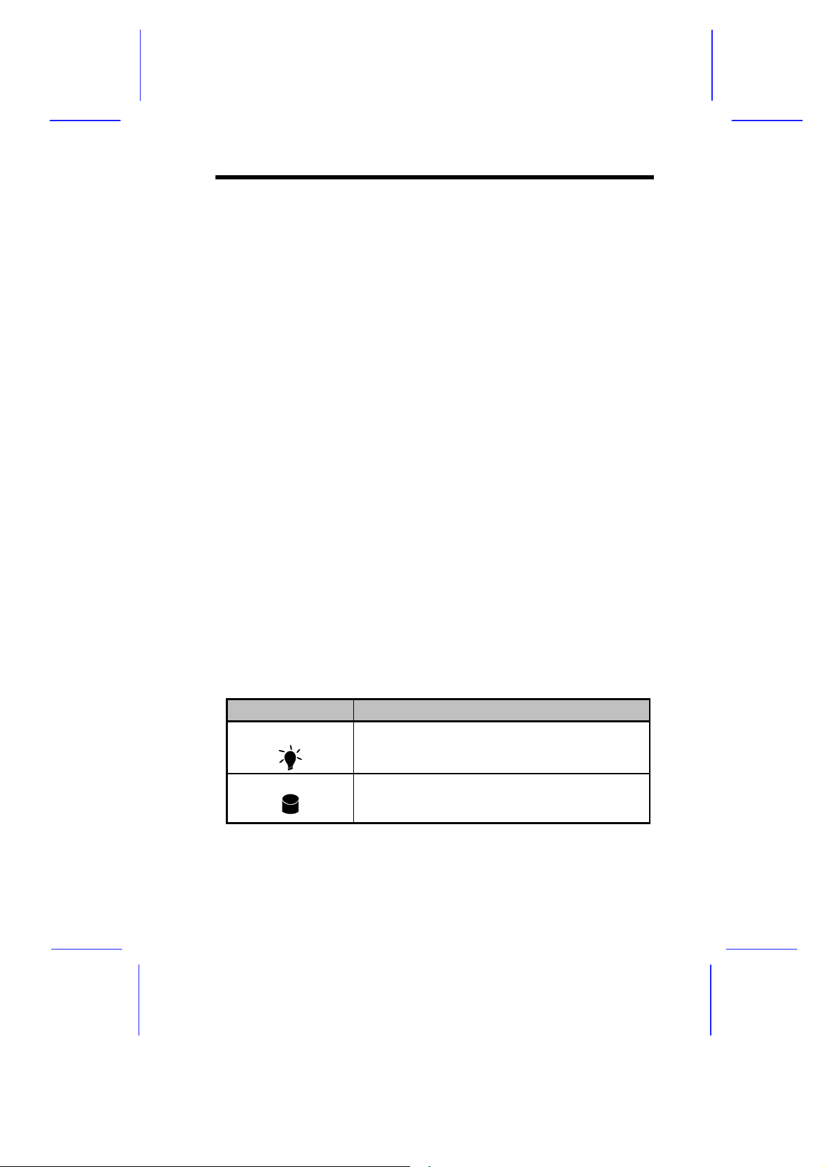
LED Indicators
Table 1-1 LED Indicator Description
LED Icons Description
Power Status Indicates that power is on. All the power supply
modules are in good condition and the system is
running on AC power.
Hard Disk Busy Indicates that at least one of the hard disks is
currently accessing.
System Introduction 1-7
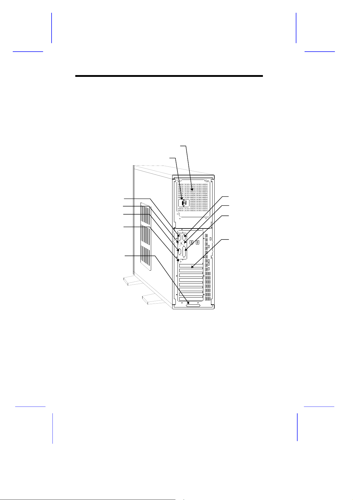
1.2.2 Rear Panel
The rear panel includes the connectors for the keyboard, mouse, VGA
monitor, printer, and serial devices. Beside the connectors are the
monitor and power sockets. On the lower section are the slot
openings for expansion boards.
Power Supply
Power Socket
COM2
Keyboard Port
Video Port
Keyboard Port
(reserved)
SCSI Expansion Slot
Figure 1-4 Rear Panel
COM1
Mouse Port
Parallel Port
Expansion Slots
1-8 System Guide

&& KK DSDSWWHUHU
Setting Up the System
This chapter tells how to install and set up the system. It gives
instructions on how to select a site for the system, prepare the system
for use, connect basic peripherals, and start up the system.
2.1 Pre-installation Requirements
2.1.1 Selecting a Site
Before unpacking and installing the system, select a suitable site for
the system for maximum efficiency. The system is suitable to set up
in an office environment.
Consider the following factors when choosing a site for the system:
•
Near a grounded power outlet
•
Clean and dust-free
•
Sturdy surface free from vibration
•
Well-ventilated and away from sources of heat
•
Secluded from electromagnetic fields produced by electrical
devices such as air conditioners, radio and TV transmitters, etc.
Setting Up the System 2-1

2.1.2 Checking the Package Contents
Check the following items from the package:
•
System Unit
•
System Guide
•
EISA Configuration Utility
•
VGA Manual and Driver Kit
•
SCSI Manuals and Driver Kit
If any of the above items is damaged or missing, contact your dealer
immediately.
Save the boxes and packing materials for future use.
2-2 System Guide
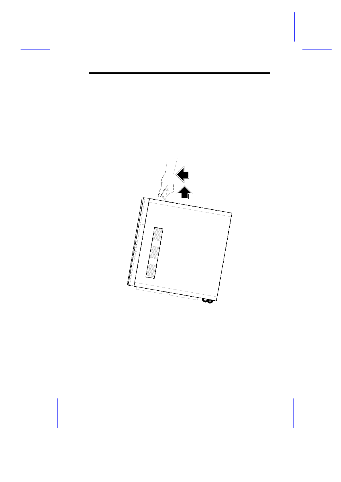
2.1.3 Transporting the System
The system housing has a handle on top and two wheels behind the
feet to facilitate moving to short distances.
When transporting the system, pull out the handle, at the same time
lifting the unit front a few inches from the ground. Slide the unit
forward with the wheels supporting the rear.
Figure 2-1 Transporting the System
Setting Up the System 2-3
 Loading...