


MITSUBISHI ELECTRI
C
C
FR-F700
Inverter
Instruction Manual
Art. no.: 166461
13 06 2013
Version F
FR-F740 EC
FR-F746 EC
MITSUBISHI ELECTRI
INDUSTRIAL AUTOMATION
Version check


Instruction Manual
Inverter FR-F700 EC
Art. no.: 166461
Version Changes / Additions / Corrections
A 04/2005 pdp First Edition
B 07/2005 pdp Section 3.8.1 Revision of the section "Note on selecting a suitable power
supply ELCB"
C 03/2006 pdp General
Section 2.4.3
D 08/2010 akl General Adaption of document version numbers (english, german)
E 10/2010 akl General
Section 7.2
General
Extension of the capacity classes by the inverters
FR-F740-02600 to 12120
Addition of the inverters FR-F746-00023 to 01160 with
IP54 protection rating
New parameter 299
Addition of a heatsink protrusion attachment
Additions:
• Voltage/current input switch
• Additional explanation to "Causes and corrective actions"
• DC feeding operation permission signal (X70), DC feeding
cancel signal (X71), PID integral value reset signal (X72)
• PID deviation limit signal (Y48), Pulse output of output power
signal (Y79), DC feeding signal (Y85)
New setting values:
• Pr. 29 "Acceleration/deceleration pattern selection" setting
value "6"
• Pr. 30 "Regenerative function selection" setting values "10",
"11", "20", "21"
• Pr. 59 "Remote function selection" setting values "11", "12",
"13"
• Pr. 128 "PID action selection" setting values "110", "111", "120",
"121"
• Pr. 167 "Output current detection operation selection" setting
values "10", "11"
• Pr. 261 "Power failure stop selection" setting values "21", "22"
• Pr. 495 "Remote output selection" setting values "10", "11"
Section 7.6
New parameters:
• Pr. 522 "Output stop frequency"
• Pr. 539 "Modbus-RTU communication check time interval"
• Pr. 653 "Speed smoothing control"
• Pr. 654 "Speed smoothing cutoff frequency"
• Pr. 553 "PID deviation limit", Pr. 554 "PID signal operation
selection", C42 (Pr. 934) "PID display bias coefficient",
C43 (Pr. 934) "PID display bias analog value", C44 (Pr. 935)
"PID display gain coefficient", C45 (Pr. 935) "PID display gain
analog value"
• Pr. 799 "Pulse increment setting for output power"
Partial changes
• Pr. 153 "Zero current detection time" setting range "0 to 10s"
• Check first when you have a trouble

Instruction Manual
Inverter FR-F700 EC
Art. no.: 166461
Version Changes / Additions / Corrections
F 06/2013 akl General New parameters:
• Pr. 147, Pr. 296, Pr. 297, Pr. 390, Pr. 414, Pr. 415, Pr. 498,
Pr. 502, Pr. 505 to Pr. 515, Pr. 561, Pr. 665, Pr. 726 to Pr. 729,
Pr. 753 to Pr. 769, Pr. 774 to Pr. 779, Pr. 826 to Pr. 865, Pr. 870,
Pr. 986, Pr. 997, Pr. 999
New setting values:
• Pr. 30, Pr. 52, Pr. 54, Pr. 128, Pr. 158, Pr. 178 to Pr. 189,
Pr. 190 to Pr. 196, Pr. 331, Pr. 332, Pr. 549, Pr. 573
Additions:
• Option connector 2
• Easy operation mode setting
• Function enhancement of Mitsubishi inverter protocol/
Modbus-RTU protocol communication
• BACnet MS/TP protocol
• PLC function
• Initial value change list
• Protective functions (LOCD, E.2, E.OP2, E.PCH, E.LCI)
• Dimensions of DC reactors FFR-HEL-H-E

P
Thank you for choosing this Mitsubishi inverter.
This instruction manual provides instructions for advanced use of the FR-F700 series inverters.
Incorrect handling might cause an unexpected fault. Before using the inverter, always read this
instruction manual to use the equipment to its optimum.
Safety instructions
Do not attempt to install, operate, maintain or inspect the inverter until you have read through
this instruction manual carefully and can use the equipment correctly. Do not use the inverter until you have a full knowledge of the equipment, safety information and instructions. In this instruction manual, the safety instruction levels are classified into "WARNING" and "CAUTION".
WARNING:
Assumes that incorrect handling may cause hazardous conditions, resulting in death
or severe injury.
E
CAUTION:
Assumes that incorrect handling may cause hazardous conditions, resulting in medium or slight injury, or may cause physical damage only.
Note that even the CAUTION level may lead to a serious consequence according to conditions.
Please follow strictly the instructions of both levels because they are important to personnel
safety.
FR-F700 EC I

MITSUBISHI ELECTRIC
P
Electric shock prevention
WARNING:
● While power is on or when the inverter is running, do not open the front cover.
Otherwise you may get an electric shock.
● Do not run the inverter with the front cover removed. Otherwise, you may access
the exposed high-voltage terminals or the charging part of the circuitry and get an
electric shock.
● Even if power is off, do not remove the front cover except for wiring or periodic
inspection. You may access the charged inverter circuits and get an electric shock.
● Before starting wiring or inspection, check to make sure that the operation panel
indicator is off, wait for at least 10 minutes after the power supply has been switched
off, and check that there are no residual voltage using a tester or the like. The
capacitor is charged with high voltage for some time after power off and it is
dangerous.
● This inverter must be earthed. Earthing must conform to the requirements of
national and local safety regulations and electrical codes. (JIS, NEC section 250,
IEC 536 class 1 and other applicable standards)
● Any person who is involved in the wiring or inspection of this equipment should
be fully competent to do the work.
● Always install the inverter before wiring. Otherwise, you may get an electric shock
or be injured.
● If your application requires by installation standards an RCD (residual current
device) as up stream protection please select according to DIN VDE 0100-530 as
following:
Single phase inverter type A or B
Three phase inverter only type B.
● Perform setting dial and key operations with dry hands to prevent an electric shock.
Otherwise you may get an electric shock. Perform setting dial and key operations
with dry hands to prevent an electric shock. Otherwise you may get an electric
shock.
● Do not subject the cables to scratches, excessive stress, heavy loads or pinching.
Otherwise you may get an electric shock.
● Do not replace the cooling fan while power is on. It is dangerous to replace the
cooling fan while power is on.
● Do no
t touch the printed circuit board or handle the cables with wet hands. You may get
an electric shock.
II

E
E
Fire prevention
CAUTION:
● Install the inverter on a nonflammable wall without holes (so that nobody can touch
the inverter heatsink on the rear side, etc.). Mounting it to or near combustible
material can cause a fire.
● If the inverter has become faulty, switch off the inverter power. A continuous flow
of large current could cause a fire.
● Do not connect a resistor directly to the DC terminals P/+, N/–. This could cause a
fire and destroy the inverter. The surface temperature of braking resistors can far
exceed 100°C for brief periods. Make sure that there is adequate protection against
accidental contact and a safe distance is maintained to other units and system
parts.
Injury prevention
CAUTION:
● Apply only the voltage specified in the instruction manual to each terminal. Otherwise, burst, damage, etc. may occur.
● Ensure that the cables are connected to the correct terminals. Otherwise, burst,
damage, etc. may occur.
● Always make sure that polarity is correct to prevent damage, etc. Otherwise, burst,
damage, etc. may occur.
● While power is on or for some time after power-off, do not touch the inverter as it
is hot and you may get burnt.
FR-F700 EC III
MITSUBISHI ELECTRIC
E
Additional instructions
Also note the following points to prevent an accidental failure, injury, electric shock, etc.
Transportation and installation
CAUTION:
● When carrying products, use correct lifting gear to prevent injury.
● Do not stack the inverter boxes higher than the number recommended.
● Ensure that installation position and material can withstand the weight of the
inverter. Install according to the information in the instruction manual.
● Do not install or operate the inverter if it is damaged or has parts missing. This can
result in breakdowns.
● When carrying the inverter, do not hold it by the front cover or setting dial; it may
fall off or fail.
● Do not stand or rest heavy objects on the product.
● Check the inverter mounting orientation is correct.
● Prevent other conductive bodies such as screws and metal fragments or other
flammable substance such as oil from entering the inverter.
● As the inverter is a precision instrument, do not drop or subject it to impact.
● Use the inverter under the following environmental conditions. Otherwise, the
inverter may be damaged
E
Operating Condition FR-F740 FR-F746
Ambient temperature
Ambient humidity 90% RH or less (non-condensing)
Storage temperature −20°C to +65°C
Atmosphere Indoors (free from corrosive gas, flammable gas, oil mist, dust and dirt)
Altitude
Vibration
Temperature applicable for a short time, e.g. in transit.
2.9m/s² or less for the 04320 or more.
Wiring
CAUTION:
● Do not install assemblies or components (e. g. power factor correction capacitors)
on the inverter output side, which are not approved from Mitsubishi.
● The direction of rotation of the motor corresponds to the direction of rotation
commands (STF/STR) only if the phase sequence (U, V, W) is maintained.
−10°C to +40/+50°C (non-freezing) −10°C to +30/+40°C (non-freezing)
The maximum temperature depends on the setting of Pr. 570.
Maximum 1000m above sea level for standard operation. After that derate by 3% for
every extra 500m up to 2500m (91%)
5.9m²
or less at 10 to 55Hz (directions of X, Y, Z axes)
IV

P
Operation
WARNING:
● When you have chosen the retry function, stay away from the equipment as it will
restart suddenly after an alarm stop.
● Since pressing STOP/RESET key may not stop output depending on the function
setting status, provide a circuit and switch separately to make an emergency stop
(power off, mechanical brake operation for emergency stop, etc.).
● Make sure that the start signal is off before resetting the inverter alarm. A failure
to do so may restart the motor suddenly.
● The inverter can be started and stopped via the serial port communications link or
the field bus. However, please note that depending on the settings of the
communications parameters it may not be possible to stop the system via these
connections if there is an error in the communications system or the data line. In
configurations like this it is thus essential to install additional safety hardware that
makes it possible to stop the system in an emergency (e.g. controller inhibit via
control signal, external motor contactor etc). Clear and unambiguous warnings
about this must be posted on site for the operating and service staff.
● The load used should be a three-phase induction motor only. Connection of any
other electrical equipment to the inverter output may damage the inverter as well
as the equipment.
● Do not modify the equipment.
● Do not perform parts removal which is not instructed in this manual. Doing so may
lead to fault or damage of the inverter.
FR-F700 EC V

MITSUBISHI ELECTRIC
E
CAUTION:
● The electronic thermal relay function does not guarantee protection of the motor
from overheating. It is recommended to install both an external thermal and PTC
thermistor for overheat protection.
● Do not use a magnetic contactor on the inverter input for frequent starting/stopping
of the inverter. Otherwise, the life of the inverter decreases.
● Use a noise filter to reduce the effect of electromagnetic interference and follow
the accepted EMC procedures for proper installation of frequency inverters. Otherwise nearby electronic equipment may be affected.
● Take appropriate measures regarding harmonics. Otherwise this can endanger
compensation systems or overload generators.
● Use a motor designed for inverter operation. (The stress for motor windings is
bigger than in line power supply).
● When parameter clear or all clear is performed, set again the required parameters
before starting operations. Each parameter returns to the initial value.
● The inverter can be easily set for high-speed operation. Before changing its setting,
fully examine the performances of the motor and machine.
● The DC braking function of the frequency inverter is not designed to continuously
hold a load. Use an electro-mechanical holding brake on the motor for this purpose.
● Before running an inverter which had been stored for a long period, always perform
inspection and test operation.
● For prevention of damage due to static electricity, touch nearby metal before
touching this product to eliminate static electricity from your body.
E
E
Diagnosis and settings
CAUTION:
● Before starting operation, confirm and adjust the parameters. A failure to do so
may cause some machines to make unexpected motions.
Emergency stop
CAUTION:
● Provide a safety backup such as an emergency brake which will prevent the
machine and equipment from hazardous conditions if the inverter fails.
● When the breaker on the inverter primary side trips, check for the wiring fault (short
circuit), damage to internal parts of the inverter, etc. Identify the cause of the trip,
then remove the cause and power on the breaker.
● When the protective function is activated (i. e. the frequency inverter switches off
with an error message), take the corresponding corrective action as described in
the inverter manual, then reset the inverter, and resume operation.
VI

E
E
Maintenance, inspection and parts replacement
CAUTION:
● Do not carry out a megger (insulation resistance) test on the control circuit of the
inverter. It will cause a failure.
Disposing the inverter
CAUTION:
● Treat as industrial waste.
General instructions
Many of the diagrams and drawings in instruction manuals show the inverter without a cover, or
partially open. Never run the inverter in this status. Always replace the cover and follow this instruction manual when operating the inverter.
FR-F700 EC VII

MITSUBISHI ELECTRIC
Symbols used in the manual
Use of instructions
Instructions concerning important information are marked separately and are displayed as follows:
NOTE Text of instruction
Use of examples
Examples are marked separately and are displayed as follows:
Example 쑴 Example text 쑶
Use of numbering in the figures
Numbering within the figures is displayed by white numbers within black circles and is explained
in a table following it using the same number, e.g.:
Use of handling instructions
Handling instructions are steps that must be carried out in their exact sequence during startup,
operation, maintenance and similar operations.
They are numbered consecutively (black numbers in white circles):
Tex t.
Tex t.
Tex t.
Use of footnotes in tables
Instructions in tables are explained in footnotes underneath the tables (in superscript). There is
a footnote character at the appropriate position in the table (in superscript).
If there are several footnotes for one table then these are numbered consecutively underneath
the table (black numbers in white circle, in superscript):
Te xt
Te xt
Te xt
VIII

Contents
1 Product checking and part identification
1.1 Inverter type . . . . . . . . . . . . . . . . . . . . . . . . . . . . . . . . . . . . . . . . . . . . . . . . . . . . . . . . 1-1
1.2 Description of the case. . . . . . . . . . . . . . . . . . . . . . . . . . . . . . . . . . . . . . . . . . . . . . . . 1-2
1.2.1 Accessory . . . . . . . . . . . . . . . . . . . . . . . . . . . . . . . . . . . . . . . . . . . . . . . . . . . 1-3
2 Installation
2.1 Removal and reinstallation of the operation panel . . . . . . . . . . . . . . . . . . . . . . . . . . . 2-1
2.2 Removal and reinstallation of the front cover. . . . . . . . . . . . . . . . . . . . . . . . . . . . . . . 2-2
2.2.1 FR-F740-00023 to 00620-EC . . . . . . . . . . . . . . . . . . . . . . . . . . . . . . . . . . . . 2-2
2.2.2 FR-F740-00770 to 12120-EC . . . . . . . . . . . . . . . . . . . . . . . . . . . . . . . . . . . . 2-3
2.2.3 FR-F746-00023 to 01160-EC . . . . . . . . . . . . . . . . . . . . . . . . . . . . . . . . . . . . 2-5
2.3 Mounting . . . . . . . . . . . . . . . . . . . . . . . . . . . . . . . . . . . . . . . . . . . . . . . . . . . . . . . . . . 2-6
2.4 Enclosure design . . . . . . . . . . . . . . . . . . . . . . . . . . . . . . . . . . . . . . . . . . . . . . . . . . . . 2-7
2.4.1 Inverter installation environment . . . . . . . . . . . . . . . . . . . . . . . . . . . . . . . . . . 2-7
2.4.2 Inverter placement . . . . . . . . . . . . . . . . . . . . . . . . . . . . . . . . . . . . . . . . . . . 2-11
2.4.3 Heatsink protrusion attachment (FR-A7CN) . . . . . . . . . . . . . . . . . . . . . . . . 2-13
Contents
3 Wiring
3.1 Inverter and peripheral devices . . . . . . . . . . . . . . . . . . . . . . . . . . . . . . . . . . . . . . . . . 3-1
3.1.1 Peripheral devices . . . . . . . . . . . . . . . . . . . . . . . . . . . . . . . . . . . . . . . . . . . . 3-3
3.2 Terminal connection diagram . . . . . . . . . . . . . . . . . . . . . . . . . . . . . . . . . . . . . . . . . . . 3-5
3.3 Main circuit connection. . . . . . . . . . . . . . . . . . . . . . . . . . . . . . . . . . . . . . . . . . . . . . . . 3-7
3.3.1 Specification of main circuit terminal. . . . . . . . . . . . . . . . . . . . . . . . . . . . . . . 3-7
3.3.2 Terminal layout and wiring . . . . . . . . . . . . . . . . . . . . . . . . . . . . . . . . . . . . . . 3-8
3.4 Control circuit specifications. . . . . . . . . . . . . . . . . . . . . . . . . . . . . . . . . . . . . . . . . . . 3-16
3.4.1 Control circuit terminals . . . . . . . . . . . . . . . . . . . . . . . . . . . . . . . . . . . . . . . 3-21
3.4.2 Wiring instructions . . . . . . . . . . . . . . . . . . . . . . . . . . . . . . . . . . . . . . . . . . . 3-23
3.4.3 Separate power supply for the control circuit . . . . . . . . . . . . . . . . . . . . . . . 3-24
3.4.4 Changing the control logic . . . . . . . . . . . . . . . . . . . . . . . . . . . . . . . . . . . . . 3-27
3.5 Connecting the operation panel/parameter unit using a connection cable . . . . . . . 3-30
3.6 RS485 terminal block . . . . . . . . . . . . . . . . . . . . . . . . . . . . . . . . . . . . . . . . . . . . . . . . 3-31
3.6.1 Communication operation . . . . . . . . . . . . . . . . . . . . . . . . . . . . . . . . . . . . . . 3-32
3.7 Connection of stand-alone option units . . . . . . . . . . . . . . . . . . . . . . . . . . . . . . . . . . 3-33
3.7.1 Magnetic contactors (MC). . . . . . . . . . . . . . . . . . . . . . . . . . . . . . . . . . . . . . 3-33
3.7.2 Connection of a brake unit (FR-BU/MT-BU5) . . . . . . . . . . . . . . . . . . . . . . . 3-35
3.7.3 Connection of the high power factor converter (FR-HC, MT-HC) . . . . . . . . 3-38
3.7.4 Connection of the power regeneration common converter FR-CV
(01160 or less) . . . . . . . . . . . . . . . . . . . . . . . . . . . . . . . . . . . . . . . . . . . . . . 3-40
3.7.5 Connection of power regeneration converter (MT-RC) (01800 or more) . . 3-41
3.7.6 Connection of the power improving DC reactor . . . . . . . . . . . . . . . . . . . . . 3-42
3.7.7 Installation of a reactor . . . . . . . . . . . . . . . . . . . . . . . . . . . . . . . . . . . . . . . . 3-43
FR-F700 EC IX

Contents
3.8 Electromagnetic compatibility (EMC) . . . . . . . . . . . . . . . . . . . . . . . . . . . . . . . . . . . . 3-44
3.8.1 Leakage currents and countermeasures . . . . . . . . . . . . . . . . . . . . . . . . . . 3-44
3.8.2 Inverter-generated noises and their reduction techniques . . . . . . . . . . . . . 3-49
3.8.3 EMC filter . . . . . . . . . . . . . . . . . . . . . . . . . . . . . . . . . . . . . . . . . . . . . . . . . . 3-52
3.8.4 Power supply harmonics. . . . . . . . . . . . . . . . . . . . . . . . . . . . . . . . . . . . . . . 3-53
3.8.5 Inverter-driven 400V class motor . . . . . . . . . . . . . . . . . . . . . . . . . . . . . . . . 3-54
4 Operation
4.1 Precautions for use of the inverter . . . . . . . . . . . . . . . . . . . . . . . . . . . . . . . . . . . . . . . 4-1
4.2 Drive the motor. . . . . . . . . . . . . . . . . . . . . . . . . . . . . . . . . . . . . . . . . . . . . . . . . . . . . . 4-4
4.3 Operation panel FR-DU07 . . . . . . . . . . . . . . . . . . . . . . . . . . . . . . . . . . . . . . . . . . . . . 4-5
4.3.1 Parts of the operation panel . . . . . . . . . . . . . . . . . . . . . . . . . . . . . . . . . . . . . 4-5
4.3.2 Basic operation (factory setting) . . . . . . . . . . . . . . . . . . . . . . . . . . . . . . . . . . 4-7
4.3.3 Easy operation mode setting (easy setting mode) . . . . . . . . . . . . . . . . . . . . 4-8
4.3.4 Operation lock. . . . . . . . . . . . . . . . . . . . . . . . . . . . . . . . . . . . . . . . . . . . . . . 4-10
4.3.5 Monitoring of output current and output voltage . . . . . . . . . . . . . . . . . . . . . 4-12
4.3.6 First priority monitor . . . . . . . . . . . . . . . . . . . . . . . . . . . . . . . . . . . . . . . . . . 4-12
4.3.7 Digital dial push . . . . . . . . . . . . . . . . . . . . . . . . . . . . . . . . . . . . . . . . . . . . . 4-12
4.3.8 Change the parameter setting value. . . . . . . . . . . . . . . . . . . . . . . . . . . . . . 4-13
4.4 Overheat protection of the motor by the inverter . . . . . . . . . . . . . . . . . . . . . . . . . . . 4-15
4.5 PU operation mode . . . . . . . . . . . . . . . . . . . . . . . . . . . . . . . . . . . . . . . . . . . . . . . . . 4-17
4.5.1 Set the set frequency to operate. . . . . . . . . . . . . . . . . . . . . . . . . . . . . . . . . 4-18
4.5.2 Use the digital dial like a potentiometer to perform operation. . . . . . . . . . . 4-19
4.5.3 Use switches to give the frequency command (multi-speed setting) . . . . . 4-20
4.5.4 Perform frequency setting by analog voltage input. . . . . . . . . . . . . . . . . . . 4-23
4.5.5 Perform frequency setting by analog current input . . . . . . . . . . . . . . . . . . . 4-25
4.6 External operation . . . . . . . . . . . . . . . . . . . . . . . . . . . . . . . . . . . . . . . . . . . . . . . . . . 4-27
4.6.1 Use the set frequency set by the operation panel (Pr. 79 = 3) . . . . . . . . . . 4-27
4.6.2 Use switches to give a start command and a frequency command
(multi-speed setting) (Pr. 4 to Pr. 6) . . . . . . . . . . . . . . . . . . . . . . . . . . . . . . 4-29
4.6.3 Perform frequency setting by analog voltage input. . . . . . . . . . . . . . . . . . . 4-32
4.6.4 Change the frequency (50Hz) of the maximum value of potentiometer
(at 5V) . . . . . . . . . . . . . . . . . . . . . . . . . . . . . . . . . . . . . . . . . . . . . . . . . . . . . 4-35
4.6.5 Perform frequency setting by analog current input . . . . . . . . . . . . . . . . . . . 4-36
4.6.6 Change the frequency (50Hz) of the maximum value of potentiometer
(at 20mA) . . . . . . . . . . . . . . . . . . . . . . . . . . . . . . . . . . . . . . . . . . . . . . . . . . 4-38
5 Basic settings
5.1 Simple mode parameter list . . . . . . . . . . . . . . . . . . . . . . . . . . . . . . . . . . . . . . . . . . . . 5-1
5.2 Increase the starting torque (Pr. 0) . . . . . . . . . . . . . . . . . . . . . . . . . . . . . . . . . . . . . . 5-3
5.3 Limit the maximum and minimum output frequency (Pr. 1, Pr. 2) . . . . . . . . . . . . . . . 5-5
5.4 When the rated motor frequency is 60Hz (Pr. 3) . . . . . . . . . . . . . . . . . . . . . . . . . . . . 5-7
5.5 Change the acceleration/deceleration time (Pr. 7, Pr. 8) . . . . . . . . . . . . . . . . . . . . . . 5-8
5.6 Energy saving operation (Pr. 60) . . . . . . . . . . . . . . . . . . . . . . . . . . . . . . . . . . . . . . . 5-10
5.7 Operation mode (Pr. 79) . . . . . . . . . . . . . . . . . . . . . . . . . . . . . . . . . . . . . . . . . . . . . 5-12
5.8 Parameter clear . . . . . . . . . . . . . . . . . . . . . . . . . . . . . . . . . . . . . . . . . . . . . . . . . . . . 5-13
5.9 All parameter clear . . . . . . . . . . . . . . . . . . . . . . . . . . . . . . . . . . . . . . . . . . . . . . . . . . 5-14
X
MITSUBISHI ELECTRIC

5.10 Parameter copy and parameter verification . . . . . . . . . . . . . . . . . . . . . . . . . . . . . . . 5-15
5.10.1 Parameter copy . . . . . . . . . . . . . . . . . . . . . . . . . . . . . . . . . . . . . . . . . . . . . 5-16
5.10.2 Parameter verification. . . . . . . . . . . . . . . . . . . . . . . . . . . . . . . . . . . . . . . . . 5-18
5.11 Initial value change list . . . . . . . . . . . . . . . . . . . . . . . . . . . . . . . . . . . . . . . . . . . . . . . 5-19
6 Parameter
6.1 Parameter overview . . . . . . . . . . . . . . . . . . . . . . . . . . . . . . . . . . . . . . . . . . . . . . . . . . 6-1
6.2 Motor torque. . . . . . . . . . . . . . . . . . . . . . . . . . . . . . . . . . . . . . . . . . . . . . . . . . . . . . . 6-39
6.2.1 Manual torque boost (Pr. 0, Pr. 46) . . . . . . . . . . . . . . . . . . . . . . . . . . . . . . 6-39
6.2.2 Simple magnetic flux vector control (Pr. 80, Pr. 90) . . . . . . . . . . . . . . . . . . 6-42
6.2.3 Slip compensation (Pr. 245 to Pr. 247) . . . . . . . . . . . . . . . . . . . . . . . . . . . . 6-43
6.2.4 Stall prevention operation (Pr. 22, Pr. 23, Pr. 48, Pr. 49, Pr. 66, Pr. 148,
Pr. 149, Pr. 154, Pr. 156, Pr. 157) . . . . . . . . . . . . . . . . . . . . . . . . . . . . . . . 6-44
6.2.5 Multiple rating (LD = Light Duty, SLD = Super Light Duty) (Pr. 570) . . . . . 6-53
6.3 Limit the output frequency . . . . . . . . . . . . . . . . . . . . . . . . . . . . . . . . . . . . . . . . . . . . 6-54
6.3.1 Maximum and minimum frequency (Pr. 1, Pr. 2, Pr. 18). . . . . . . . . . . . . . . 6-54
6.3.2 Avoid mechanical resonance points (Frequency jump)
(Pr. 31 to Pr. 36) . . . . . . . . . . . . . . . . . . . . . . . . . . . . . . . . . . . . . . . . . . . . . 6-56
6.4 Set V/f pattern . . . . . . . . . . . . . . . . . . . . . . . . . . . . . . . . . . . . . . . . . . . . . . . . . . . . . 6-58
6.4.1 Base frequency, voltage (Pr. 3, Pr. 19, Pr. 47) . . . . . . . . . . . . . . . . . . . . . . 6-58
6.4.2 Load pattern selection (Pr. 14) . . . . . . . . . . . . . . . . . . . . . . . . . . . . . . . . . . 6-60
6.4.3 Adjustable 5 points V/f (Pr. 71, Pr. 100 to Pr. 109) . . . . . . . . . . . . . . . . . . . 6-61
6.5 Frequency setting by external terminals . . . . . . . . . . . . . . . . . . . . . . . . . . . . . . . . . 6-63
6.5.1 Multi-speed setting operation
(Pr. 4 to Pr. 6, Pr. 24 to Pr. 27, Pr. 232 to Pr. 239) . . . . . . . . . . . . . . . . . . . 6-63
6.5.2 Jog operation (Pr. 15, Pr. 16) . . . . . . . . . . . . . . . . . . . . . . . . . . . . . . . . . . . 6-66
6.5.3 Input compensation of multi-speed and remote setting (Pr. 28) . . . . . . . . . 6-70
6.5.4 Remote setting function (Pr. 59) . . . . . . . . . . . . . . . . . . . . . . . . . . . . . . . . . 6-71
6.6 Acceleration and deceleration . . . . . . . . . . . . . . . . . . . . . . . . . . . . . . . . . . . . . . . . . 6-75
6.6.1 Acceleration and deceleration time
(Pr. 7, Pr. 8, Pr. 20, Pr. 21, Pr. 44, Pr. 45, Pr. 147) . . . . . . . . . . . . . . . . . . 6-75
6.6.2 Starting frequency and start-time hold function (Pr. 13, Pr. 571) . . . . . . . . 6-79
6.6.3 Acceleration and deceleration pattern (Pr. 29, Pr. 140 to Pr. 143) . . . . . . . 6-81
6.7 Selection and protection of a motor . . . . . . . . . . . . . . . . . . . . . . . . . . . . . . . . . . . . . 6-85
6.7.1 Motor protection from overheat (Electronic thermal relay function)
(Pr. 9, Pr. 51, Pr. 561, Pr. 986) . . . . . . . . . . . . . . . . . . . . . . . . . . . . . . . . . . 6-85
6.7.2 Applied motor (Pr. 71). . . . . . . . . . . . . . . . . . . . . . . . . . . . . . . . . . . . . . . . . 6-93
6.8 Motor brake and stop operation . . . . . . . . . . . . . . . . . . . . . . . . . . . . . . . . . . . . . . . . 6-94
6.8.1 DC injection brake (Pr. 10 to Pr. 12) . . . . . . . . . . . . . . . . . . . . . . . . . . . . . . 6-94
6.8.2 Selection of a regenerative brake and DC feeding (Pr. 30, Pr. 70). . . . . . . 6-97
6.8.3 Stop selection (Pr. 250) . . . . . . . . . . . . . . . . . . . . . . . . . . . . . . . . . . . . . . 6-105
6.8.4 Output stop function (Pr. 522). . . . . . . . . . . . . . . . . . . . . . . . . . . . . . . . . . 6-107
Contents
FR-F700 EC XI

Contents
6.9 Function assignment of external terminals. . . . . . . . . . . . . . . . . . . . . . . . . . . . . . . 6-109
6.9.1 Input terminal function selection (Pr. 178 to Pr. 189) . . . . . . . . . . . . . . . . 6-109
6.9.2 Inverter output shutoff signal (MRS signal, Pr. 17) . . . . . . . . . . . . . . . . . . 6-112
6.9.3 Operation condition selection of second function selection signal
(Terminal RT, Pr. 155) . . . . . . . . . . . . . . . . . . . . . . . . . . . . . . . . . . . . . . . 6-114
6.9.4 Start signal selection (Terminal STF, STR, STOP, Pr. 250) . . . . . . . . . . . 6-116
6.9.5 Output terminal function selection (Pr. 190 to Pr. 196) . . . . . . . . . . . . . . . 6-120
6.9.6 Detection of output frequency
(SU, FU, FU2, Pr. 41 to Pr. 43, Pr. 50, Pr. 870) . . . . . . . . . . . . . . . . . . . . 6-127
6.9.7 Output current detection function
(Y12, Y13, Pr. 150 to Pr. 153, Pr. 166, Pr. 167) . . . . . . . . . . . . . . . . . . . . 6-130
6.9.8 Remote output function (REM, Pr. 495 to Pr. 497) . . . . . . . . . . . . . . . . . . 6-133
6.9.9 Pulse train output of output power (Y79 signal, Pr. 799) . . . . . . . . . . . . . 6-135
6.10 Monitor display and monitor output signals . . . . . . . . . . . . . . . . . . . . . . . . . . . . . . 6-136
6.10.1 Speed display and speed setting (Pr. 37, Pr. 144, Pr. 505) . . . . . . . . . . . 6-136
6.10.2 DU/PU monitor display selection (Pr. 52, Pr. 54, Pr. 158, Pr. 170,
Pr. 171, Pr. 268, Pr. 563, Pr. 564, Pr. 891). . . . . . . . . . . . . . . . . . . . . . . . 6-138
6.10.3 CA, AM terminal function selection (Pr. 55, Pr. 56, Pr. 867, Pr. 869) . . . . 6-146
6.10.4 Terminal CA, AM calibration
[C0 (Pr. 900), C1 (Pr. 901), C8 (Pr. 930) to C11 (Pr. 931)]. . . . . . . . . . . . 6-148
6.11 Operation selection at power failure. . . . . . . . . . . . . . . . . . . . . . . . . . . . . . . . . . . . 6-153
6.11.1 Automatic restart (Pr. 57, Pr. 58, Pr. 162 to Pr. 165, Pr. 299, Pr. 611). . . 6-153
6.11.2 Power failure signal (Y67 signal) . . . . . . . . . . . . . . . . . . . . . . . . . . . . . . . 6-161
6.11.3 Power failure-time deceleration-to-stop function (Pr. 261 to Pr. 266). . . . 6-162
6.12 Operation setting at alarm occurrence . . . . . . . . . . . . . . . . . . . . . . . . . . . . . . . . . . 6-169
6.12.1 Retry function (Pr. 65, Pr. 67 to Pr. 69). . . . . . . . . . . . . . . . . . . . . . . . . . . 6-169
6.12.2 Alarm code output selection (Pr. 76). . . . . . . . . . . . . . . . . . . . . . . . . . . . . 6-173
6.12.3 Input/output phase loss protection selection (Pr. 251, Pr. 872) . . . . . . . . 6-175
6.13 Energy saving operation and energy saving monitor . . . . . . . . . . . . . . . . . . . . . . . 6-176
6.13.1 Energy saving control and optimum excitation control (Pr. 60). . . . . . . . . 6-176
6.13.2 Energy saving monitor (Pr. 52, Pr. 54, Pr. 158, Pr. 891 to Pr. 899) . . . . . 6-178
6.14 Motor noise, noise reduction . . . . . . . . . . . . . . . . . . . . . . . . . . . . . . . . . . . . . . . . . 6-185
6.14.1 PWM carrier frequency and Soft-PWM control
(Pr. 72, Pr. 240, Pr. 260). . . . . . . . . . . . . . . . . . . . . . . . . . . . . . . . . . . . . . 6-185
6.14.2 Speed smoothing control (Pr. 653, Pr. 654) . . . . . . . . . . . . . . . . . . . . . . . 6-187
6.15 Frequency setting by analog input (terminals 1, 2 and 4) . . . . . . . . . . . . . . . . . . . 6-188
6.15.1 Analog input selection (Pr. 73, Pr. 267) . . . . . . . . . . . . . . . . . . . . . . . . . . 6-188
6.15.2 Analog input compensation (Pr. 73, Pr. 242, Pr. 243, Pr. 252, Pr. 253) . . 6-195
6.15.3 Input filter time constant (Pr. 74). . . . . . . . . . . . . . . . . . . . . . . . . . . . . . . . 6-198
6.15.4 Bias and gain of frequency setting voltage (current)
[Pr. 125, Pr. 126, Pr. 241, C2 (Pr. 902) to C7 (Pr. 905)] . . . . . . . . . . . . . . 6-199
6.15.5 4mA input check of current input (Pr. 573, Pr. 777, Pr. 778) . . . . . . . . . . 6-207
6.16 Misoperation prevention and parameter setting restriction . . . . . . . . . . . . . . . . . . 6-213
6.16.1 Reset selection/disconnected PU detection/PU stop selection (Pr. 75) . . 6-213
6.16.2 Parameter write selection (Pr. 77) . . . . . . . . . . . . . . . . . . . . . . . . . . . . . . 6-218
6.16.3 Reverse rotation prevention selection (Pr. 78) . . . . . . . . . . . . . . . . . . . . . 6-220
6.16.4 User groups (Pr. 160, Pr. 172 to Pr. 174) . . . . . . . . . . . . . . . . . . . . . . . . . 6-221
6.16.5 Password function (Pr. 296, Pr. 297) . . . . . . . . . . . . . . . . . . . . . . . . . . . . 6-224
XII
MITSUBISHI ELECTRIC

6.17 Selection of operation mode and operation location . . . . . . . . . . . . . . . . . . . . . . . 6-229
6.17.1 Operation mode selection (Pr. 79) . . . . . . . . . . . . . . . . . . . . . . . . . . . . . . 6-229
6.17.2 Operation mode at power on (Pr. 79, Pr. 340) . . . . . . . . . . . . . . . . . . . . . 6-242
6.17.3 Operation command source and speed command source during
communication operation (Pr. 338, Pr. 339, Pr. 550, Pr. 551) . . . . . . . . . 6-244
6.18 Communication operation and setting . . . . . . . . . . . . . . . . . . . . . . . . . . . . . . . . . . 6-252
6.18.1 PU connector . . . . . . . . . . . . . . . . . . . . . . . . . . . . . . . . . . . . . . . . . . . . . . 6-253
6.18.2 RS485 terminals . . . . . . . . . . . . . . . . . . . . . . . . . . . . . . . . . . . . . . . . . . . . 6-256
6.18.3 Initial settings and specifications of RS485 communication
(Pr. 117 to Pr. 124, Pr. 331 to Pr. 337, Pr. 341, Pr. 502, Pr. 549, Pr. 779)
6.18.4 Communication E²PROM write selection (Pr. 342). . . . . . . . . . . . . . . . . . 6-264
6.18.5 Operation selection at communication error (Pr. 502, Pr. 779). . . . . . . . . 6-264
6.18.6 Mitsubishi inverter protocol (computer link communication) . . . . . . . . . . . 6-268
6.18.7 Modbus-RTU communication
(Pr. 331, Pr. 332, Pr. 334, Pr. 343, Pr. 502, Pr. 539, Pr. 549, Pr. 779). . . 6-289
6.18.8 BACnet MS/TP protocol (Pr. 52, Pr. 774 to Pr. 776, Pr. 331, Pr. 332,
Pr. 390, Pr. 549, Pr. 726 to Pr. 729) . . . . . . . . . . . . . . . . . . . . . . . . . . . . . 6-310
6.18.9 Protocol Implementation Conformance Statement – PICS. . . . . . . . . . . . 6-326
6.18.10 Operation by PLC function
(Pr. 414, Pr. 415, Pr. 498, Pr. 506 to Pr. 515, Pr. 826 to Pr. 865) . . . . . . 6-327
6.19 PID control . . . . . . . . . . . . . . . . . . . . . . . . . . . . . . . . . . . . . . . . . . . . . . . . . . . . . . . 6-328
6.19.1 PID control (Pr. 127 to Pr. 134, Pr. 553, Pr. 554, Pr. 575 to Pr. 577) . . . . 6-328
6.19.2 Bias and gain calibration for PID displayed value
[Pr. 241, Pr. 759, C42 (Pr. 934) to C45 (Pr. 935)]. . . . . . . . . . . . . . . . . . . 6-346
6.19.3 Pre-charge function (Pr. 760 to Pr. 769) . . . . . . . . . . . . . . . . . . . . . . . . . . 6-350
6.19.4 Second PID function (Pr. 753 to Pr. 758, Pr. 765 to Pr. 769) . . . . . . . . . . 6-358
6.19.5 Advanced PID function (pump function) (Pr. 554, Pr. 575 to Pr. 591) . . . 6-361
6.20 Special operation . . . . . . . . . . . . . . . . . . . . . . . . . . . . . . . . . . . . . . . . . . . . . . . . . . 6-375
6.20.1 Commercial power supply-inverter switchover function
(Pr. 57, Pr. 58, Pr. 135 to Pr. 139, Pr. 159) . . . . . . . . . . . . . . . . . . . . . . . 6-375
6.20.2 Traverse function (Pr. 592 to Pr. 597). . . . . . . . . . . . . . . . . . . . . . . . . . . . 6-383
6.20.3 Regeneration avoidance function (Pr. 665, Pr. 882 to Pr. 886) . . . . . . . . 6-386
6.21 Useful functions . . . . . . . . . . . . . . . . . . . . . . . . . . . . . . . . . . . . . . . . . . . . . . . . . . . 6-389
6.21.1 Cooling fan operation selection (Pr. 244) . . . . . . . . . . . . . . . . . . . . . . . . . 6-389
6.21.2 Display of the life of the inverter parts (Pr. 255 to Pr. 259). . . . . . . . . . . . 6-390
6.21.3 Maintenance timer alarm (Pr. 503, Pr. 504) . . . . . . . . . . . . . . . . . . . . . . . 6-394
6.21.4 Current average value monitor signal (Pr. 555 to Pr. 557) . . . . . . . . . . . . 6-395
6.21.5 Free parameters (Pr. 888, Pr. 889). . . . . . . . . . . . . . . . . . . . . . . . . . . . . . 6-399
6.21.6 Initiating a fault (Pr. 997). . . . . . . . . . . . . . . . . . . . . . . . . . . . . . . . . . . . . . 6-400
6.21.7 Setting multiple parameters as a batch (Pr. 999) . . . . . . . . . . . . . . . . . . . 6-402
6.22 Setting of parameter unit and operation panel . . . . . . . . . . . . . . . . . . . . . . . . . . . . 6-408
6.22.1 PU display language selection (Pr. 145). . . . . . . . . . . . . . . . . . . . . . . . . . 6-408
6.22.2 Operation panel frequency setting/key lock operation selection
(Pr. 161) . . . . . . . . . . . . . . . . . . . . . . . . . . . . . . . . . . . . . . . . . . . . . . . . . . 6-409
6.22.3 Buzzer control (Pr. 990) . . . . . . . . . . . . . . . . . . . . . . . . . . . . . . . . . . . . . . 6-409
6.22.4 PU contrast adjustment (Pr. 991) . . . . . . . . . . . . . . . . . . . . . . . . . . . . . . . 6-410
. . 6-261
Contents
FR-F700 EC XIII

Contents
6.23 Setting of FR-PU07-01. . . . . . . . . . . . . . . . . . . . . . . . . . . . . . . . . . . . . . . . . . . . . . 6-411
6.23.1 PID display bias/gain setting menu. . . . . . . . . . . . . . . . . . . . . . . . . . . . . . 6-412
6.23.2 Unit selection for the PID parameter/PID monitored items (Pr. 759) . . . . 6-413
6.23.3 PID set point direct setting menu . . . . . . . . . . . . . . . . . . . . . . . . . . . . . . . 6-415
6.23.4 3-line monitor selection (Pr. 774 to Pr.776) . . . . . . . . . . . . . . . . . . . . . . . 6-416
7 Troubleshooting
7.1 List of alarm display . . . . . . . . . . . . . . . . . . . . . . . . . . . . . . . . . . . . . . . . . . . . . . . . . . 7-2
7.2 Causes and corrective actions. . . . . . . . . . . . . . . . . . . . . . . . . . . . . . . . . . . . . . . . . . 7-4
7.3 Reset method of protective function. . . . . . . . . . . . . . . . . . . . . . . . . . . . . . . . . . . . . 7-23
7.4 LED display . . . . . . . . . . . . . . . . . . . . . . . . . . . . . . . . . . . . . . . . . . . . . . . . . . . . . . . 7-25
7.5 Check and clear of the alarm history . . . . . . . . . . . . . . . . . . . . . . . . . . . . . . . . . . . . 7-26
7.6 Check first when you have troubles . . . . . . . . . . . . . . . . . . . . . . . . . . . . . . . . . . . . . 7-28
7.6.1 Motor does not start . . . . . . . . . . . . . . . . . . . . . . . . . . . . . . . . . . . . . . . . . . 7-28
7.6.2 Motor or machine is making abnormal acoustic noise . . . . . . . . . . . . . . . . 7-30
7.6.3 Inverter generates abnormal noise . . . . . . . . . . . . . . . . . . . . . . . . . . . . . . . 7-30
7.6.4 Motor generates heat abnormally . . . . . . . . . . . . . . . . . . . . . . . . . . . . . . . . 7-30
7.6.5 Motor rotates in the opposite direction . . . . . . . . . . . . . . . . . . . . . . . . . . . . 7-31
7.6.6 Speed greatly differs from the setting . . . . . . . . . . . . . . . . . . . . . . . . . . . . . 7-31
7.6.7 Acceleration/deceleration is not smooth . . . . . . . . . . . . . . . . . . . . . . . . . . . 7-31
7.6.8 Speed varies during operation . . . . . . . . . . . . . . . . . . . . . . . . . . . . . . . . . . 7-32
7.6.9 Operation mode is not changed properly . . . . . . . . . . . . . . . . . . . . . . . . . . 7-32
7.6.10 Operation panel (FR-DU07) display is not operating . . . . . . . . . . . . . . . . . 7-33
7.6.11 Motor current is too large . . . . . . . . . . . . . . . . . . . . . . . . . . . . . . . . . . . . . . 7-33
7.6.12 Speed does not accelerate . . . . . . . . . . . . . . . . . . . . . . . . . . . . . . . . . . . . . 7-34
7.6.13 Unable to write parameter setting . . . . . . . . . . . . . . . . . . . . . . . . . . . . . . . . 7-35
7.6.14 Power lamp is not lit . . . . . . . . . . . . . . . . . . . . . . . . . . . . . . . . . . . . . . . . . . 7-35
7.7 Meters and measuring methods. . . . . . . . . . . . . . . . . . . . . . . . . . . . . . . . . . . . . . . . 7-36
7.7.1 Measurement of powers . . . . . . . . . . . . . . . . . . . . . . . . . . . . . . . . . . . . . . . 7-37
7.7.2 Measurement of voltages and use of PT . . . . . . . . . . . . . . . . . . . . . . . . . . 7-38
7.7.3 Measurement of currents . . . . . . . . . . . . . . . . . . . . . . . . . . . . . . . . . . . . . . 7-38
7.7.4 Use of CT and transducer. . . . . . . . . . . . . . . . . . . . . . . . . . . . . . . . . . . . . . 7-39
7.7.5 Measurement of inverter input power factor . . . . . . . . . . . . . . . . . . . . . . . . 7-39
7.7.6 Measurement of converter output voltage
(across terminals P/+ and N/–) . . . . . . . . . . . . . . . . . . . . . . . . . . . . . . . . . . 7-39
XIV
MITSUBISHI ELECTRIC

8 Maintenance and inspection
8.1 Inspection. . . . . . . . . . . . . . . . . . . . . . . . . . . . . . . . . . . . . . . . . . . . . . . . . . . . . . . . . .8-1
8.1.1 Daily inspection. . . . . . . . . . . . . . . . . . . . . . . . . . . . . . . . . . . . . . . . . . . . . . . 8-1
8.1.2 Periodic inspection . . . . . . . . . . . . . . . . . . . . . . . . . . . . . . . . . . . . . . . . . . . . 8-1
8.1.3 Daily and periodic inspection . . . . . . . . . . . . . . . . . . . . . . . . . . . . . . . . . . . . 8-2
8.1.4 Display of the life of the inverter parts. . . . . . . . . . . . . . . . . . . . . . . . . . . . . . 8-4
8.1.5 Checking the inverter and converter modules . . . . . . . . . . . . . . . . . . . . . . . 8-7
8.1.6 Cleaning . . . . . . . . . . . . . . . . . . . . . . . . . . . . . . . . . . . . . . . . . . . . . . . . . . . . 8-8
8.1.7 Replacement of parts . . . . . . . . . . . . . . . . . . . . . . . . . . . . . . . . . . . . . . . . . . 8-8
8.1.8 Inverter replacement. . . . . . . . . . . . . . . . . . . . . . . . . . . . . . . . . . . . . . . . . . 8-16
8.2 Measurements on the main circuit . . . . . . . . . . . . . . . . . . . . . . . . . . . . . . . . . . . . . . 8-17
8.2.1 Insulation resistance test using megger . . . . . . . . . . . . . . . . . . . . . . . . . . . 8-17
8.2.2 Pressure test. . . . . . . . . . . . . . . . . . . . . . . . . . . . . . . . . . . . . . . . . . . . . . . . 8-17
8.2.3 Measurement of voltages and currents. . . . . . . . . . . . . . . . . . . . . . . . . . . . 8-18
A Appendix
A.1 Specifications FR-F740-00023 to -01160 . . . . . . . . . . . . . . . . . . . . . . . . . . . . . . . . . A-1
A.2 Specifications FR-F740-01800 to -12120 . . . . . . . . . . . . . . . . . . . . . . . . . . . . . . . . . A-2
A.3 Specifications FR-F746-00023 to -01160 . . . . . . . . . . . . . . . . . . . . . . . . . . . . . . . . . A-3
A.4 Common specifications . . . . . . . . . . . . . . . . . . . . . . . . . . . . . . . . . . . . . . . . . . . . . . . A-4
A.5 Outline dimension drawings . . . . . . . . . . . . . . . . . . . . . . . . . . . . . . . . . . . . . . . . . . . A-6
A.5.1 FR-F740-00023 to -00126 . . . . . . . . . . . . . . . . . . . . . . . . . . . . . . . . . . . . . . A-6
A.5.2 FR-F740-00170 to -00380 . . . . . . . . . . . . . . . . . . . . . . . . . . . . . . . . . . . . . . A-7
A.5.3 FR-F740-00470 and -00620 . . . . . . . . . . . . . . . . . . . . . . . . . . . . . . . . . . . . A-8
A.5.4 FR-F740-00770 to -01160 . . . . . . . . . . . . . . . . . . . . . . . . . . . . . . . . . . . . . . A-9
A.5.5 FR-F740-01800 . . . . . . . . . . . . . . . . . . . . . . . . . . . . . . . . . . . . . . . . . . . . . A-10
A.5.6 FR-F740-02160 to -03610 . . . . . . . . . . . . . . . . . . . . . . . . . . . . . . . . . . . . . A-11
A.5.7 FR-F740-04320 to -06830 . . . . . . . . . . . . . . . . . . . . . . . . . . . . . . . . . . . . . A-12
A.5.8 FR-F740-07700 and -08660 . . . . . . . . . . . . . . . . . . . . . . . . . . . . . . . . . . . A-13
A.5.9 FR-F740-09620 to -12120 . . . . . . . . . . . . . . . . . . . . . . . . . . . . . . . . . . . . . A-14
A.5.10 FR-F746-00023 to -00126 . . . . . . . . . . . . . . . . . . . . . . . . . . . . . . . . . . . . . A-15
A.5.11 FR-F746-00170 and -00250 . . . . . . . . . . . . . . . . . . . . . . . . . . . . . . . . . . . A-15
A.5.12 FR-F746-00310 and -00380 . . . . . . . . . . . . . . . . . . . . . . . . . . . . . . . . . . . A-16
A.5.13 FR-F746-00470 and -00620 . . . . . . . . . . . . . . . . . . . . . . . . . . . . . . . . . . . A-16
A.5.14 FR-F746-00770 . . . . . . . . . . . . . . . . . . . . . . . . . . . . . . . . . . . . . . . . . . . . . A-17
A.5.15 FR-F746-00930 and -01160 . . . . . . . . . . . . . . . . . . . . . . . . . . . . . . . . . . . A-17
A.5.16 DC reactors . . . . . . . . . . . . . . . . . . . . . . . . . . . . . . . . . . . . . . . . . . . . . . . . A-18
A.5.17 Panel cutting for the heatsink protrusion attachment . . . . . . . . . . . . . . . . . A-20
A.5.18 Operation panel FR-DU07 . . . . . . . . . . . . . . . . . . . . . . . . . . . . . . . . . . . . . A-21
A.5.19 Parameter unit FR-PU07 . . . . . . . . . . . . . . . . . . . . . . . . . . . . . . . . . . . . . . A-21
A.6 Parameter list with instruction codes . . . . . . . . . . . . . . . . . . . . . . . . . . . . . . . . . . . . A-22
A.7 Specification change . . . . . . . . . . . . . . . . . . . . . . . . . . . . . . . . . . . . . . . . . . . . . . . . A-41
A.7.1 SERIAL number check . . . . . . . . . . . . . . . . . . . . . . . . . . . . . . . . . . . . . . . A-41
Contents
FR-F700 EC XV

Contents
XVI
MITSUBISHI ELECTRIC
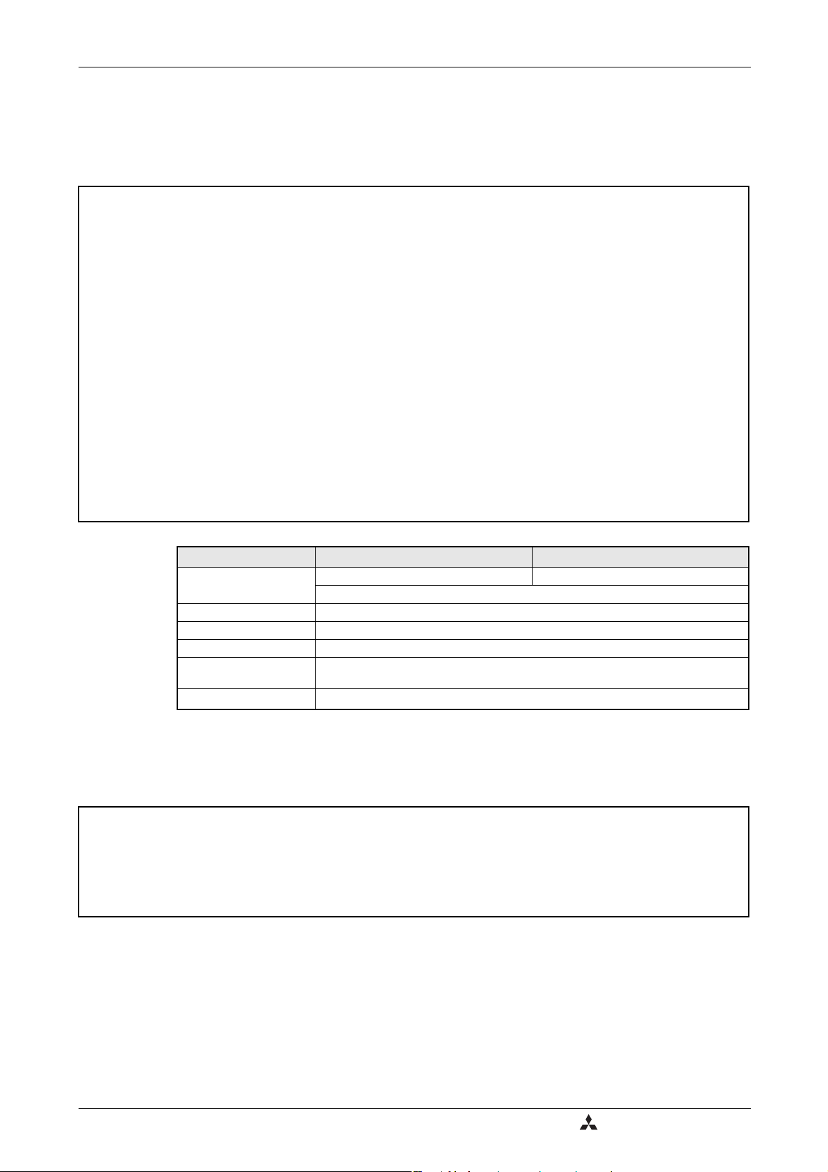
Product checking and part identification Inverter type
Symbol Voltage Class
F740
Three-phase
400V class
Symbol Type num ber
00023
to
12120
5-digit display
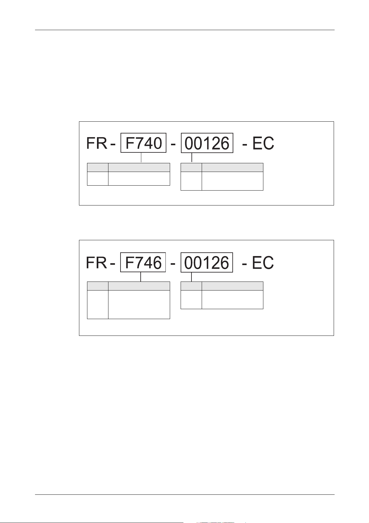
Symbol Voltage Class
F746
Three-phase
400V class
waterproof structure IP54
(standard IEC 60529: 2001)
specification
Symbol Type num ber
00023
to
01160
5-digit display
1 Product checking and part identification
Unpack the inverter and check the capacity plate on the front cover and the rating plate on the
inverter side face to ensure that the product agrees with your order and the inverter is intact.
1.1 Inverter type
I001331E
Fig. 1-1: Inverter Type FR-F740 EC
Fig. 1-2: Inverter type FR-F746 EC
I001393E
FR-F700 EC 1 - 1
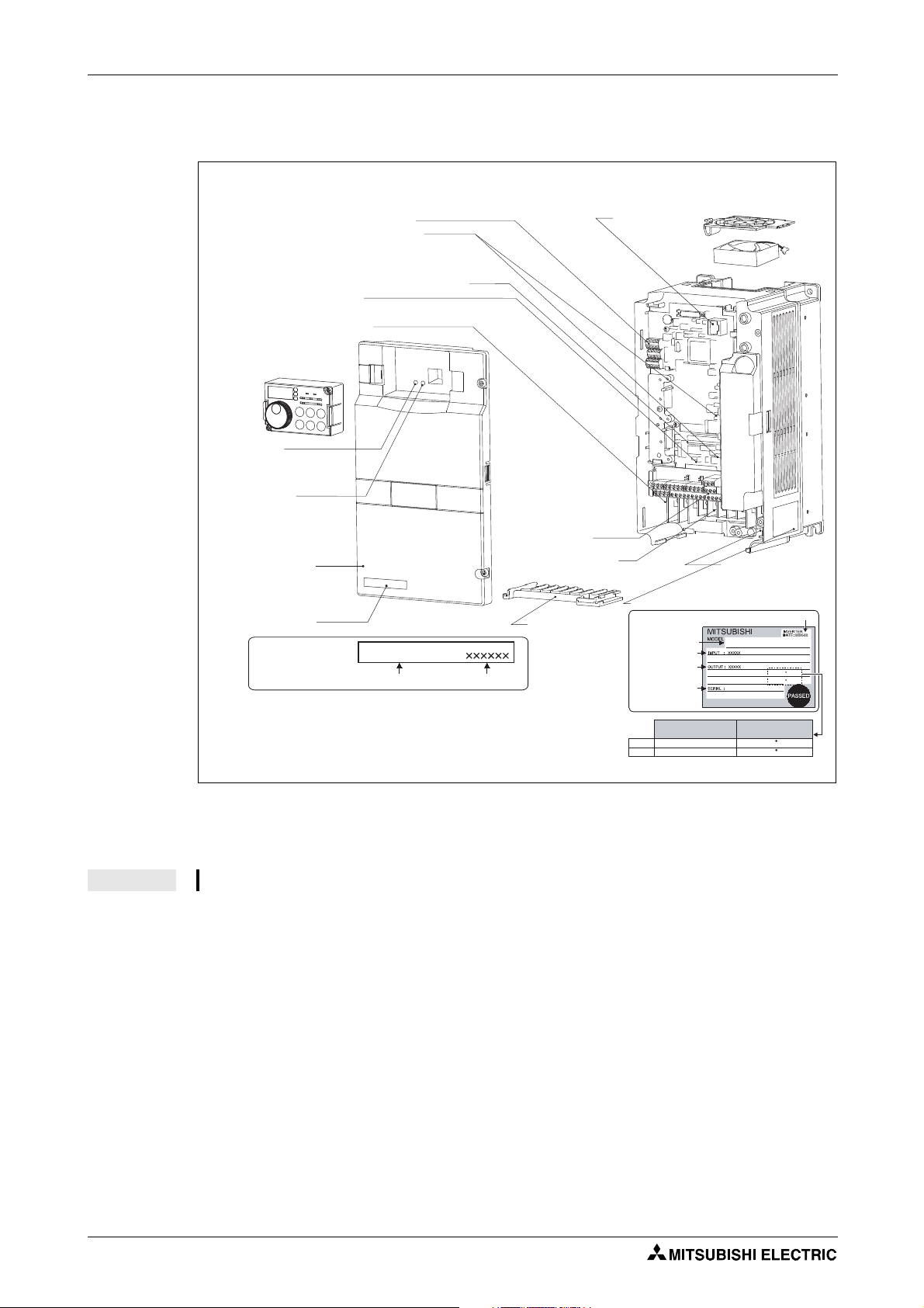
Description of the case Product checking and part identification
Capacity plate
Capacity plate
Front cover
Overload current
rating
Ambient
temperature
Inverter type
Inverter type Serial number
RS485 terminal
PU connector
(refer to section 3.5)
Rating plate
Comb shaped
wiring cover
(refer to section 2.3)
Control c ircuit
terminal block
(refer to section 3.4)
Main circuit terminal
block (refer to section
3.3)
CHARGE lamp
Lit when power is
supplied to the main
circuit.
POWER lamp
Lit when the control circuit
(R1/L11, S1/L21) is supplied
with power.
ALARM lamp
Lit when the inverter
is in the alarm status
(major fault)
(refer to chapter 7)
Connector with/without EMC filter
(refer to section 3.8.3)
AU/PTC-switchover
(refer to section 3.4)
Connector for plug-in option connection
(Refer to the instruction manual of options)
There are two connection connectors, called
connector 1 and connector 2 from the top.
Cooling fan
(refer to section 8.1.7)
Operation panel FR-DU07
(refer to section 4.3)
Output rating
Voltage/current input switch
(refer to section 3.2)
Input rating
Serial number
Production year-month
1.2 Description of the case
NOTE For removal and reinstallation of covers, refer to section 2.2.
FR-F740-00126-EC
Fig. 1-3: Appearance and Structure
FR-F740-00126-EC
LD 120% 60s, 150% 3s 50 C
SLD 110% 60s, 120% 3s 40 C
LD (50 C) XXA
SLD (40 C) XXA
I000990E_F
1 - 2
Product checking and part identification Description of the case
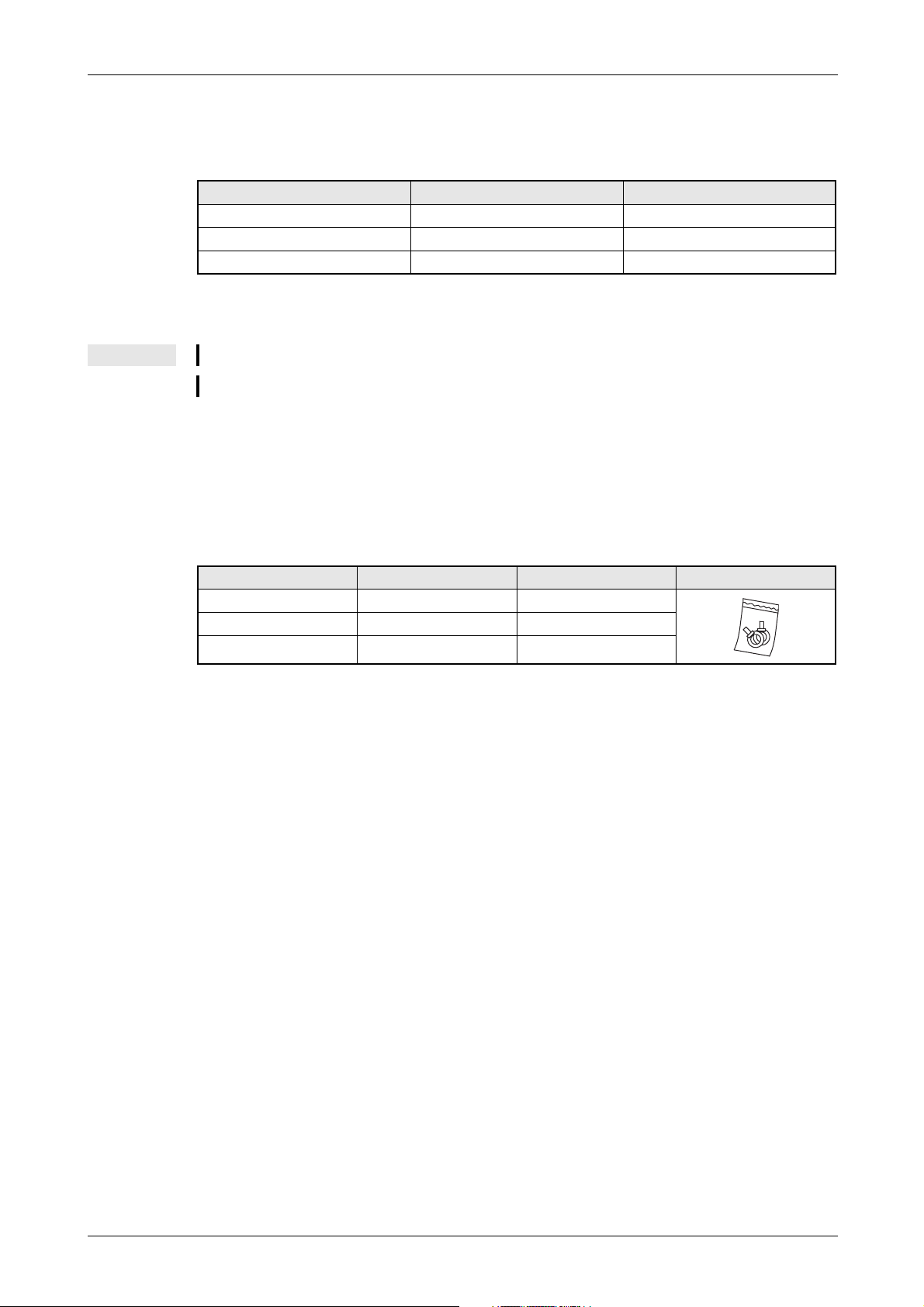
1.2.1 Accessory
Fan cover fixing screws
Capacity Screw Size[mm] Number
00083/00126 M3 × 35 1
00170 to 00380 M4 × 40 2
00470/00620 M4 × 50 1
Tab. 1-1: Fan cover fixing screws
NOTES The fan cover fixing screws are not delivered with models 00620 or less.
For removal and reinstallation of the cooling fans, refer to section 8.1.7.
DC reactor
For models 01800 or more the supplied DC reactor has to be installed.
Eyebolts
Eyebolts for hanging the inverter are delivered with the models 00770 to 06830.
Capacity Eyebolt size Number
00770 M8 2
00930 to 03610 M10 2
04320 to 06830 M12 2
Tab. 1-2: Size of the delivered eyebolts
FR-F700 EC 1 - 3

Description of the case Product checking and part identification
1 - 4
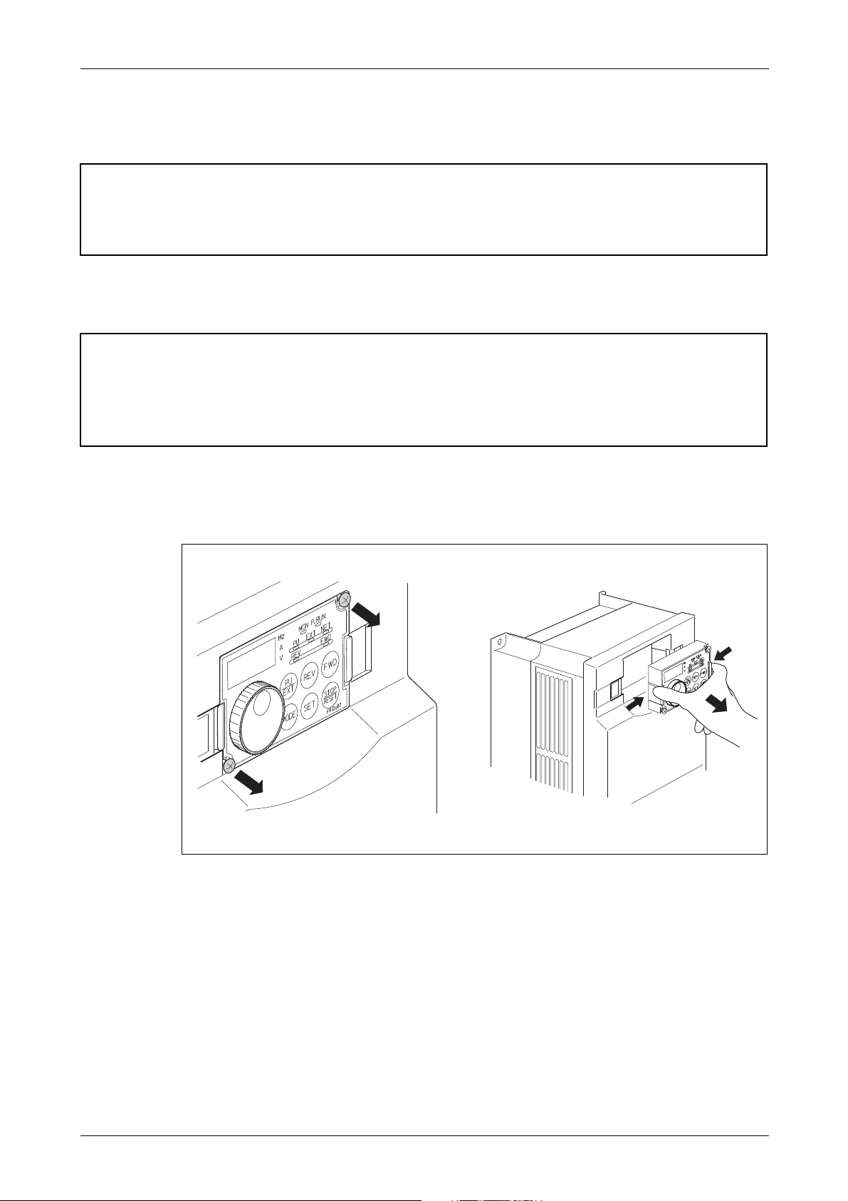
Installation Removal and reinstallation of the operation panel
Loosen the screws
Remove operation panel
2 Installation
CAUTION:
Check that packing is not removed at removal or reinstallation of a cover. If packing
E
2.1 Removal and reinstallation of the operation panel
E
is removed, contact the sales representative. If the inverter is used with packing
removed, the inverter does not conform to IP54.
CAUTION:
● If the operation panel of the inverter FR-F746 is removed from the front cover, the
inverter does not conform to IP54.
● The operation panel (FR-DU07) is designed to IP54 specifications. Do not install
the FR-DU07 mounted on the FR-F740 EC.
Loosen the two screws on the operation panel. (These screws cannot be removed.)
Push the left and right hooks of the operation panel and pull the operation panel toward you
to remove.
I000991E
Fig. 2-1: Removal and reinstallation of the operation panel
When reinstalling the operation panel, insert it straight to reinstall securely and tighten the
FR-F700 EC 2 - 1
fixed screws of the operation panel.
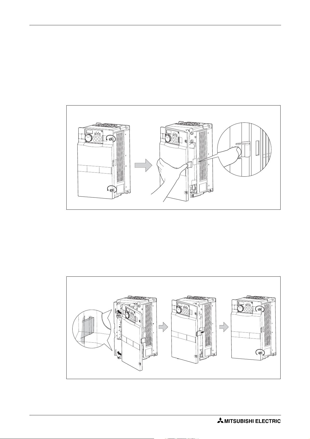
Removal and reinstallation of the front cover Installation
Loosen the screws
Remove front cover
Installation hook
Insert hooks into the sockets Press front cover against
the inverter
Tighten the installation
screws
2.2 Removal and reinstallation of the front cover
2.2.1 FR-F740-00023 to 00620-EC
Removal
Loosen the installation screws of the front cover.
Pull the front cover toward you to remove by pushing an installation hook using left fixed
hooks as supports.
Fig. 2-2: Removal of the front cover
Reinstallation
Insert the two fixed hooks on the left side of the front cover into the sockets of the inverter.
Using the fixed hooks as supports, securely press the front cover against the inverter.
(Although installation can be done with the operation panel mounted, make sure that a
connector is securely fixed.)
Tighten the installation screws and fix the front cover.
I000992E
2 - 2
I000993E
Fig. 2-3: Reinstallation of the front cover
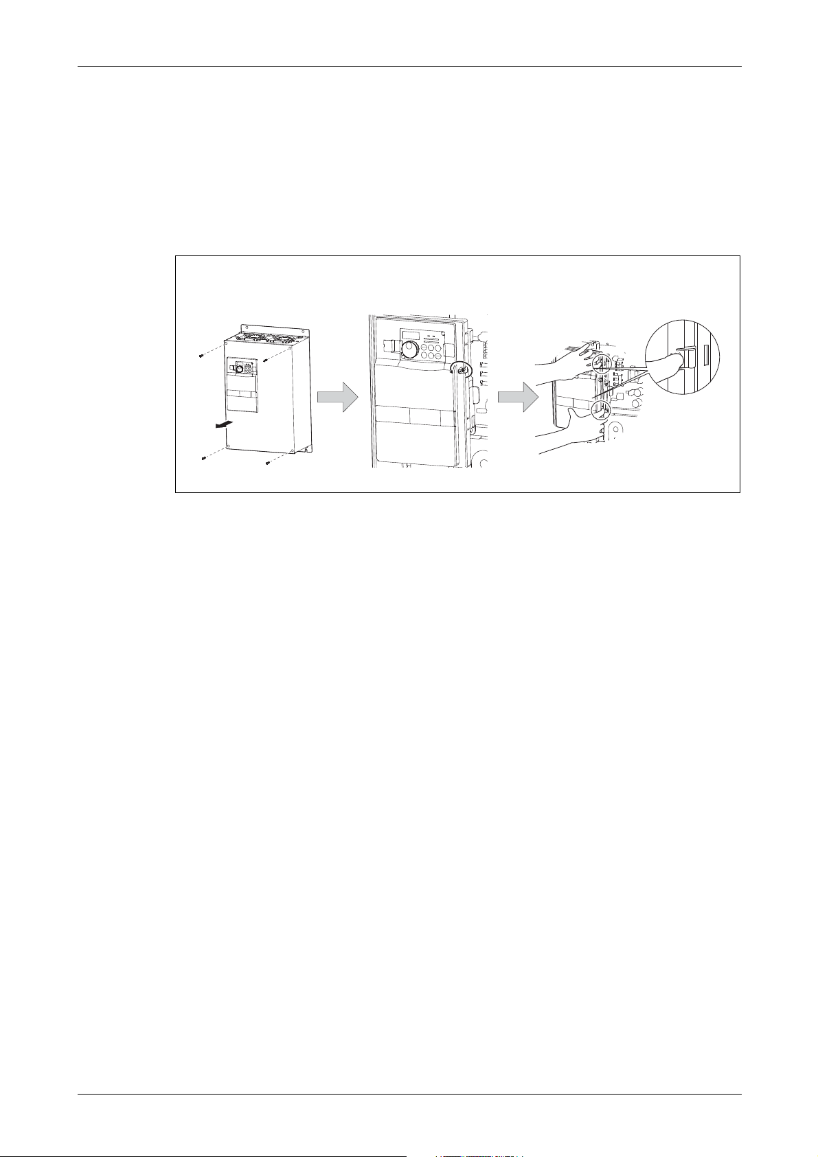
Installation Removal and reinstallation of the front cover
Loosen the screw of front
cover 1
Remove front cover
Installation hook
Cover 1
Cover 2
Loosen the screw of front
cover 2
2.2.2 FR-F740-00770 to 12120-EC
Removal
Loosen the installation screws of the front cover 1.
Loosen the installation screws of the front cover 2.
Pull the front cover 2 toward you to remove by pushing an installation hook on the right side
using left fixed hooks as supports.
Fig. 2-4: Removal of the front cover
I000994E
FR-F700 EC 2 - 3
Removal and reinstallation of the front cover Installation
Insert hooks into the sockets
Press front cover 2 against the inverter
Fix front cover 2 with the
installation screws
Fix front cover 1 with the
installation screws
Reinstallation
Insert the two fixed hooks on the left side of the front cover 2 into the sockets of the inverter.
Using the fixed hooks as supports, securely press the front cover 2 against the inverter.
(Although installation can be done with the operation panel mounted, make sure that a
connector is securely fixed.)
Fix the front cover 2 with the installation screws.
Fix the front cover 1 with the installation screws.
Fig. 2-5: Reinstallation of the front cover
NOTES For the FR-F740-04320 or more, the front cover 1 is separated into two parts.
Fully make sure that the front cover has been reinstalled securely. Always tighten the installation screws of the front cover.
The same serial number is printed on the capacity plate of the front cover and the rating
plate of the inverter. Before reinstalling the front cover, check the serial numbers to ensure
that the cover removed is reinstalled to the inverter from where it was removed.
I000995E
2 - 4
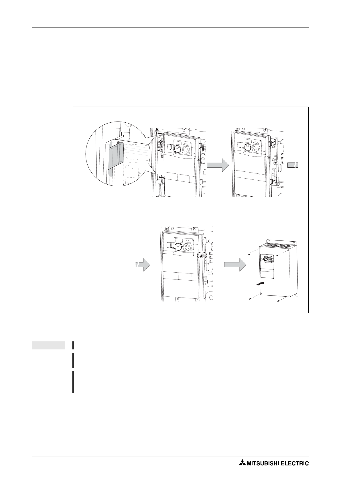
Installation Removal and reinstallation of the front cover
Metal chain
Removal/installation
hook
Connection cable
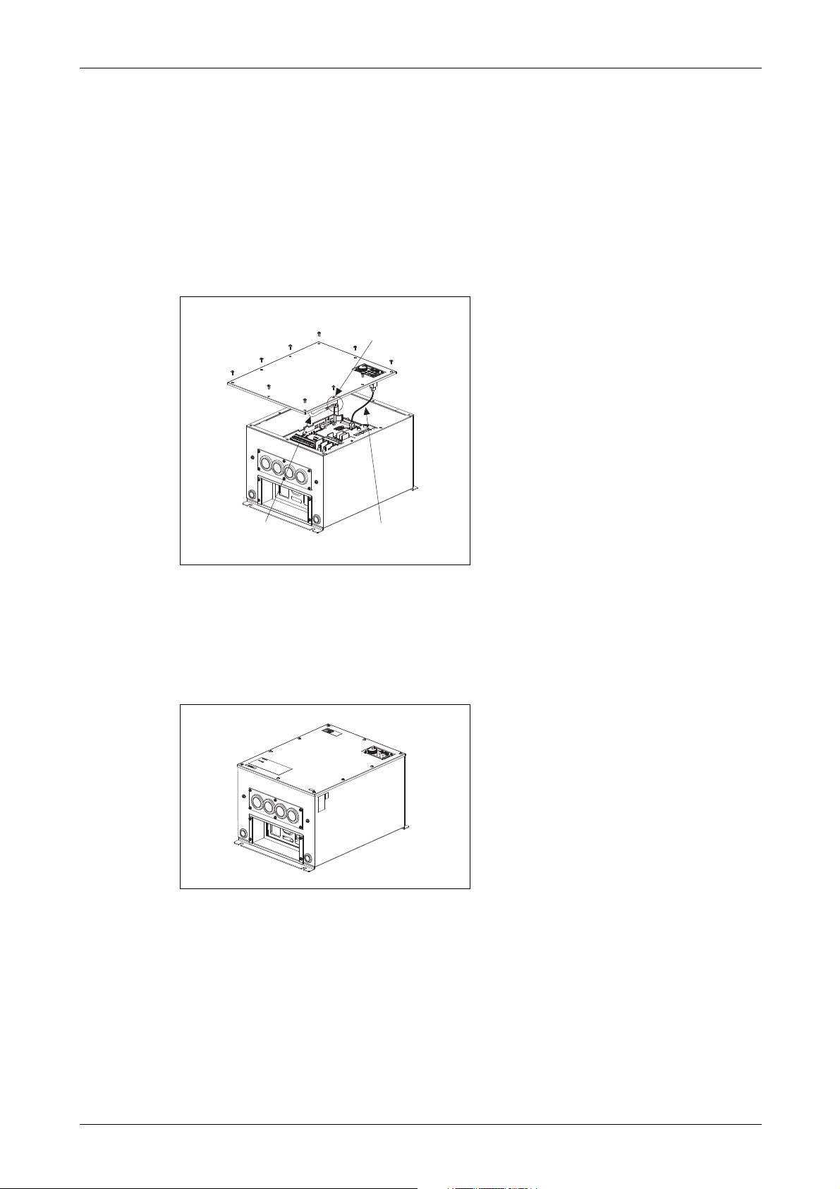
2.2.3 FR-F746-00023 to 01160-EC
Removal
Loosen the installation screw of the front cover.
Since the metal chain is mounted to the front cover, remove the front cover slowly.
Remove the connection cable from the PU connector.
Remove the hook of metal chain end from the inverter.
Remove the front cover.
Fig. 2-6:
Removal of the front cover
I001394E
Reinstallation
Install the hook of metal chain end to the inverter.
Connect the connection cable to the PU connector.
Fix the front cover using the installation screws securely. When installing the front cover,
be careful not to pinch the connection cable or the metal chain.
Fig. 2-7:
Reinstallation of the front cover
I001395E
FR-F700 EC 2 - 5
Mounting Installation
00023 to 00620 CAUTION:
When encasing multiple inverters, follow the
instructions on page 2-11.
00770 to 12120
R
e
f
e
r
t
o
F
i
g
.
2
-
1
0
Fix six positions for the FR-F740-04320
to 08660 and fix eight positions for the
FR-F740-09620 to 12120.
Direct sunlight Vibration (≥ 5,9 m/s²)
(≥ 2.9m/s² for the 04320 or more)
High temperature,
high humidity
Horizontal placement
Vertical mounting
(When installing two or more
inverters, install them in
parallel.)
Transportation by holding
the front cover
Oil mist, flammable gas,
corrosive gas, fluff, dust, etc.
Mounting to combustible
material
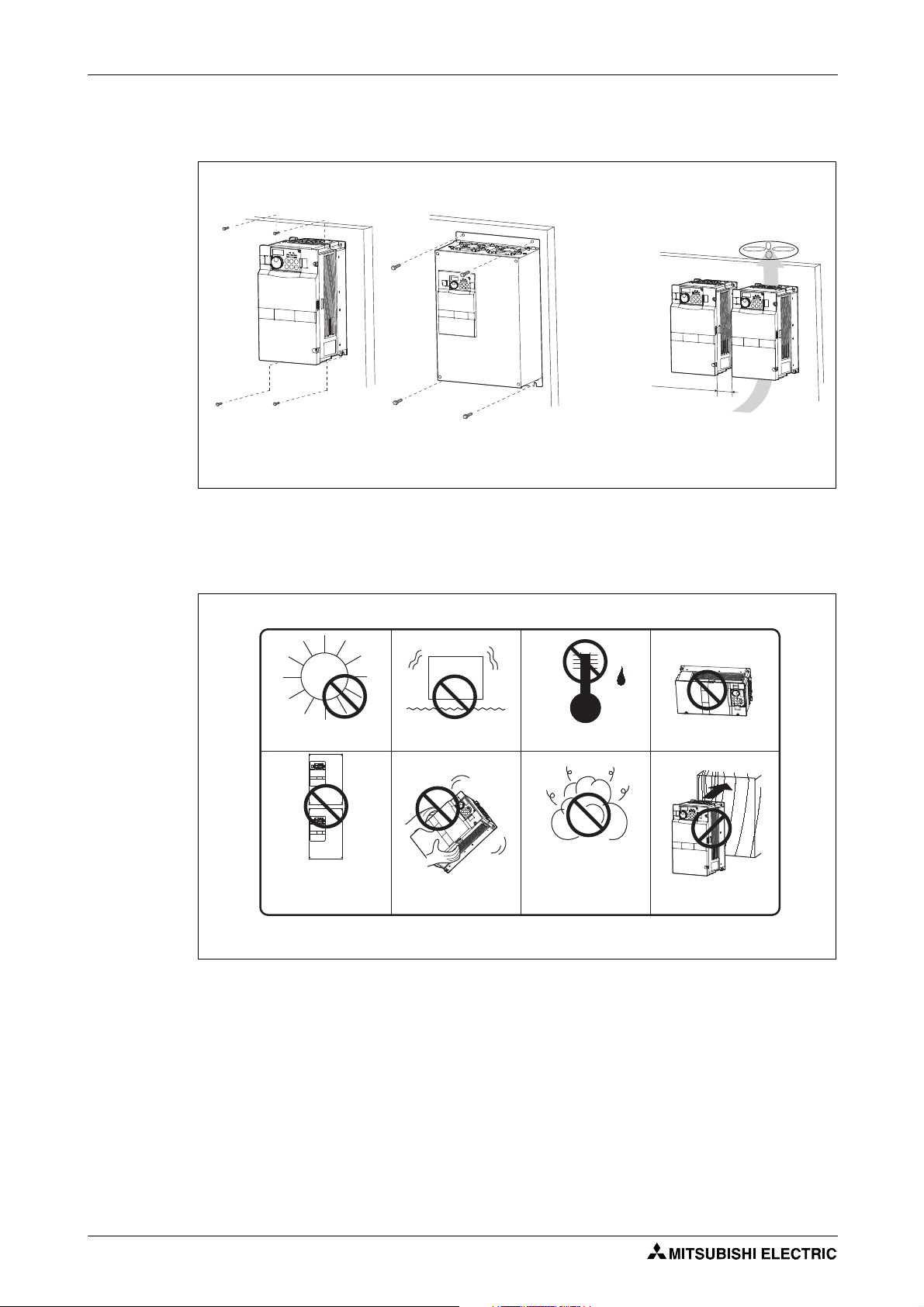
2.3 Mounting
I000997E
Fig. 2-8: Installation on the panel
The inverter consists of precision mechanical and electronic parts. Never install or handle it in
any of the following conditions as doing so could cause an operation fault or failure.
I000998E
Fig. 2-9: Conditions, that could cause an operation fault or failure
2 - 6

Installation Enclosure design
2.4 Enclosure design
When an inverter enclosure is to be designed and manufactured, heat generated by contained
equipment, etc., the environment of an operating place, and others must be fully considered to
determine the enclosure structure, size and equipment layout. The inverter unit uses many
semiconductor devices. To ensure higher reliability and long period of operation, operate the inverter in the ambient environment that completely satisfies the equipment specifications.
2.4.1 Inverter installation environment
As the inverter installation environment should satisfy the standard specifications indicated in
the following table, operation in any place that does not meet these conditions not only deteriorates the performance and life of the inverter, but also causes a failure. Refer to the following
points and take adequate measures.
Item FR-F740 FR-F746
Ambient
temperature
Ambient humidity 90% RH or less (non-condensing)
Atmosphere Free from corrosive and explosive gases, dust and dirt
Maximum altitude 1000m or less
Vibration 5.9m/s² or less (2.9m/s² or less for the 04320 or more)
150 % overload
capacity
120 % overload
capacity (Initial setting)
−10 °C to +50°C
(non-freezing)
−10 °C to +40°C
(non-freezing)
at 10 to 55Hz (directions of X, Y, Z axes)
−10°C to +40°C
(non-freezing)
−10°C to +30°C
(non-freezing)
Tab. 2-1: Environmental standard specifications of inverter
Temperature
The permissible ambient temperature of the inverter FR-F740 is between −10 and +50°C (when
LD is set) or −10 and +40°C (when SLD is set) and of the inverter FR-F746 is between −10 and
+40°C (when LD is set) or −10 and +30°C (when SLD is set). Always operate the inverter within
this temperature range. Operation outside this range will considerably shorten the service lives
of the semiconductors, parts, capacitors and others. Take the following measures so that the
ambient temperature of the inverter falls within the specified range.
● Measures against high temperature
– Use a forced ventilation system or similar cooling system. (Refer to page 2-10.)
– Install the enclosure in an air-conditioned electrical chamber.
– Block direct sunlight.
– Provide a shield or similar plate to avoid direct exposure to the radiated heat and wind
of a heat source.
– Ventilate the area around the enclosure well.
● Measures against low temperature
– Provide a space heater in the enclosure.
– Do not power off the inverter. (Keep the start signal of the inverter off.)
● Sudden temperature changes
– Select an installation place where temperature does not change suddenly.
– Avoid installing the inverter near the air outlet of an air conditioner.
– If temperature changes are caused by opening/closing of a door, install the inverter away
from the door.
FR-F700 EC 2 - 7

Enclosure design Installation
Humidity
Normally operate the inverter within the 45 to 90% range of the ambient humidity. Too high humidity will pose problems of reduced insulation and metal corrosion. On the other hand, too low
humidity may produce a spatial electrical breakdown. The insulation distance specified in
JEM1103 "Control Equipment Insulator" is defined as humidity 45 to 85%.
● Measures against high humidity
– Make the enclosure enclosed, and provide it with a hygroscopic agent.
– Take dry air into the enclosure from outside.
– Provide a space heater in the enclosure.
● Measures against low humidity
What is important in fitting or inspection of the unit in this status is to discharge your body
(static electricity) beforehand and keep your body from contact with the parts and patterns,
besides blowing air of proper humidity into the enclosure from outside.
● Measures against condensation
Condensation may occur if frequent operation stops change the in-enclosure temperature
suddenly or if the outside air temperature changes suddenly. Condensation causes such
faults as reduced insulation and corrosion.
– Take the measures against high humidity.
– Do not power off the inverter. (Keep the start signal of the inverter off.)
Dust, dirt, oil mist
Dust and dirt will cause such faults as poor contact of contact points, reduced insulation or reduced cooling effect due to moisture absorption of accumulated dust and dirt, and in-enclosure
temperature rise due to clogged filter.
In the atmosphere where conductive powder floats, dust and dirt will cause such faults as malfunction, deteriorated insulation and short circuit in a short time.
Since oil mist will cause similar conditions, it is necessary to take adequate measures.
● Measures against dust, dirt, oil mist
– Place in a totally enclosed enclosure.
Take measures if the in-enclosure temperature rises. (Refer to page 2-10.)
– Purge air.
Pump clean air from outside to make the in-enclosure pressure higher than the outsideair pressure.
Corrosive gas, salt damage
If the inverter is exposed to corrosive gas or to salt near a beach, the printed board patterns and
parts will corrode or the relays and switches will result in poor contact. In such places, take the
measures against dust, dirt, oil mist.
2 - 8

Installation Enclosure design
Explosive, flammable gases
As the inverter is non-explosion proof, it must be contained in an explosion proof enclosure.
In places where explosion may be caused by explosive gas, dust or dirt, an enclosure cannot be
used unless it structurally complies with the guidelines and has passed the specified tests. This
makes the enclosure itself expensive (including the test charges).
The best way is to avoid installation in such places and install the inverter in a non-hazardous
place.
Highland
Use the inverter at the altitude of within 1000m.
If it is used at a higher place, it is likely that thin air will reduce the cooling effect and low air pressure will deteriorate dielectric strength.
Vibration, impact
The vibration resistance of the inverter is up to 5.9m/s² (2.9m/s² for the 04320 or more) at 10 to
55Hz frequency and 1mm amplitude for the directions of X, Y, Z axes.
Vibration or impact, if less than the specified value, applied for a long time may make the mechanism loose or cause poor contact to the connectors.
Especially when impact is imposed repeatedly, caution must be taken as the part pins are likely
to break.
● Countermeasures
– Provide the enclosure with rubber vibration isolators.
– Strengthen the structure to prevent the enclosure from resonance.
– Install the enclosure away from sources of vibration.
FR-F700 EC 2 - 9

Enclosure design Installation
heatsink
heat pipe
Cooling system types for inverter enclosure
From the enclosure that contains the inverter, the heat of the inverter and other equipment
(transformers, lamps, resistors, etc.) and the incoming heat such as direct sunlight must be dissipated to keep the in-enclosure temperature lower than the permissible temperatures of the inenclosure equipment including the inverter.
The cooling systems are classified as follows in terms of the cooling calculation method.
● Cooling by natural heat dissipation from the enclosure surface (Totally enclosed type)
● Cooling by heat sink (Aluminium fin, etc.)
● Cooling by ventilation (Forced ventilation type, pipe ventilation type)
● Cooling by heat exchanger or cooler (Heat pipe, cooler, etc.)
Cooling System Enclosure Structure Comment
Natural
cooling
Natural ventilation
(Enclosed, open type)
I001000E
Natural ventilation
(Totally enclosed
type)
Low in cost and generally used, but the enclosure
size increases as the inverter capacity increases.
For relatively small capacities.
Being a totally enclosed type, the most appropriate
for hostile environment having dust, dirt, oil mist,
etc. The enclosure size increases depending on the
inverter capacity.
I001001E
Forced
cooling
Heatsink cooling
I001002E
Forced ventilation
I001003E
Heat pipe
I001004E
Having restrictions on the heatsink mounting position and area, and designed for relative small
capacities.
For general indoor installation. Appropriate for
enclosure downsizing and cost reduction, and often
used.
Totally enclosed type for enclosure downsizing.
Tab. 2-2: Cooling system types for inverter enclosure
2 - 10

Installation Enclosure design
Ambient temperature and humidity Clearances (side) Clearances (front)
Leave enough clearances and take
cooling measures.
Inverter
Measurement
position
5cm
5cm
5cm
01160 or less
01800 or more
≥ 10cm
≥ 5cm
≥ 5cm
≥ 10cm
≥ 20cm
≥ 10cm≥ 10cm
≥ 20cm
1cm or more for 00083 or less
≥ 5cm
Measurement
position
Inverter
LD/SLD
Temperature [°C]
FR-F740 FR-F746
150 % −10 to +50 −10 to +40
120 % −10 to +40 −10 to +30
Ambient
humidity:
90%
Initial setting
1cm or more for 00083 or less
2.4.2 Inverter placement
Clearances around the inverter
Always observe the specified minimum clearances to ensure good heat dissipation and adequate accessibility of the frequency inverter for servicing.
I001005E
Fig. 2-10: Clearances
NOTES
NOTE
For replacing the cooling fan of the 04320 or more, 30cm of space is necessary in front of
the inverter. Refer to section 8.1.7 for fan replacement.
Since the fan cover of the inverter FR-F746 is fixed with screws, leave enough clearances
so that the screws can be removed with a driver and such.
It is not necessary to leave spaces on both sides of the inverter FR-F746.
Inverter mounting orientation
Mount the inverter on a wall as specified. Do not mount it horizontally or any other way.
Above the inverter
Heat is blown up from inside the inverter by the small fan built in the unit. Any equipment placed
above the inverter should be heat resistant.
The ambient temperature should be 50°C or less for the inverter FR-F740 and 40°C or less
for the inverter FR-F746 at a distance of 5cm from the centre bottom of the inverter.
FR-F700 EC 2 - 11

Enclosure design Installation
a) Horizontal arrangement b) Vertical arrangement
Inverter
InverterInverter
Inverter Inverter Inverter
Guide
Guide
Guide
Enclosure Enclosure
Good example!
Inverter
Inverter
Bad example!
Arrangement of multiple inverters
When multiple inverters are placed in the same enclosure, generally arrange them horizontally
as shown in the figure (a). When it is inevitable to arrange them vertically to minimize space, take
such measures as to provide guides since heat from the bottom inverters can increase the temperatures in the top inverters, causing inverter failures.
I001006E
Fig. 2-11: Arrangement of multiple inverters
NOTE When mounting multiple inverters, fully take caution not to make the ambient temperature of
the inverter higher than the permissible value by providing ventilation and increasing the
enclosure size.
Placement of ventilation fan and inverter
Heat generated in the inverter is blown up from the bottom of the unit as warm air by the cooling
fan. When installing a ventilation fan for that heat, determine the place of ventilation fan installation after fully considering an air flow. (Air passes through areas of low resistance. Make an airway and airflow plates to expose the inverter to cool air.)
Fig. 2-12: Placement of ventilation fan and inverter
2 - 12
I001007E

Installation Enclosure design
Upper installation
frame
Lower installation
frame
Shift
Shift
Upper installation
frame (rear side)
Lower installation
frame (rear side)
Removal
Removal
2.4.3 Heatsink protrusion attachment (FR-A7CN)
When encasing the inverter in an enclosure, the generated heat amount in an enclosure can be
greatly reduced by installing the heatsink portion of the inverter outside the enclosure. When installing the inverter in a compact enclosure, etc., this installation method is recommended.
For the FR-F740-00023 to 03610, a heatsink can be protruded outside the enclosure using a
heatsink protrusion attachment (FR-A7CN). For a panel cut dimension drawing and an installation procedure of the heatsink protrusion attachment (FR-A7CN) to the inverter, refer to a
manual of "heatsink protrusion attachment".
For the panel cut dimensions of the inverters FR-F740-04320 and more refer to Fig. A-18 in the
appendix. The heatsink protrusion attachment is not required for external cooling of these inverters.
Shift and removal of a rear side installation frame
● FR-F740-05470 to 06830
One installation frame is attached to each of the upper and lower part of the inverter. Change
the position of the rear side installation frame on the upper and lower side of the inverter to
the frontside as shown below. When changing the installation frames, make sure that the
installation orientation is correct.
Fig. 2-13:
Shifting the rear side installation frame
(05470 to 06830)
● FR-F740-04320, 04810, 07700 or more
Two installation frames each are attached to the upper and lower part of the inverter. Remove
the rear side installation frame on the upper and lower side of the inverter as shown below.
Fig. 2-14:
Removing the rear side installation frame
(04320, 04810, 07700 or more)
I001381E
FR-F700 EC 2 - 13
I001382E

Enclosure design Installation
Enclosure
Installation
frame
Cooling
wind
Exhausted air
Inverter
Inside the
enclosure
Dimension of the
outside of the
enclosure
Finger guard
Enclosure
* For the FR-F740-05470 or more, there are
finger guards behind the enclosure. Therefore,
the thickness of the panel should be less than
10mm and also do not place anything around
finger guards to avoid contact with the finger
guards.
Inverter Type D1 [mm]
FR-F740-04320, 04810 185
FR-F740-05470 to 12120 184
Installation of the inverter
Push the inverter heatsink portion outside the enclosure and fix the enclosure and inverter with
upper and lower installation frame.
E
I001383E
Fig. 2-15: Installation of the inverter
CAUTION:
● Having a cooling fan, the cooling section which comes out of the enclosure can
not be used in the environment of waterdrops, oil, mist, dust, etc.
● Be careful not to drop screws, dust etc. into the inverter and cooling fan section.
2 - 14

Wiring Inverter and peripheral devices
3-phase AC power supply
Use within the permissible power
supply specifications of the inverter.
(Refer to Appendix A.)
Moulded case circuit breaker (MCCB)
or earth leakage circuit breaker (ELB),
fuse
The breaker must be selected carefully
since an in-rush current flows in the
inverter at power on.
(Refer to section 3.1.1.)
Reactor (FR-BAL-B, FFR-HEL-(H)-E)
Reactors (option) should be used when power harmonics measures are taken, the power
factor is to be improved or the inverter is installed near a large power supply system
(1000kVA or more). The inverter may be damaged if you do not use reactors.
Select the reactor according to the model. For the 01160 or less, remove the jumpers
across terminals P/+ and P1 to connect to the DC reactor. (Refer to section 3.7.6.)
For the 01160 or less: FFR-HEL-(H)-E
For the 01800 or more, a DC reactor is supplied. Always install the reactor.
AC reactor
(FR-BAL-B)
DC reactor
(FFR-HEL-(H)-E)
High power factor
converter
(FR-HC , MT-HC )
Power supply harmonics can
be greatly suppressed.
Install this as required.
Power regeneration
common converter
(FR-CV )
Power regeneration
converter (MT-RC )
Greater braking capability
is obtained.
Install this as required.
Resistor unit
(FR-BR , MT-BR5 )
The regenerative braking
capability of the inverter can
be exhibited fully.
Install this as required.
Brake unit
(FR-BU , MT-BU5 )
Compatible with the 01160 or less.
Compatible with the 01800 or more.
Magnetic contactor (MC)
Install the magnetic contactor to ensure
safety. Do not use this magnetic con tactor
to start and stop the inverter.
Doing so will cause the inverter life to be
shortened.
(Refer to section 3.1.1.)
PLC
RS485 terminal block
The inverter can be connected
with a computer such as a PLC
and with GOT (Human Machine
Interface– HMI). It supports
Mitsubishi inverter protocol,
Modbus-RTU (binary) protocol
and BACnet MS/TP protocol.
Inverter (FR-F700 EC)
The life of the inverter is
influenced by ambient
temperature. The ambient
temperature should be as low as
possible within the permissible
range. Especially when mounting
the inverter inside an enclosure,
take cautions of the ambient
temperature.
(Refer to section 2.4.2.)
Wrong wiring might lead to
damage of the inverter. The
control signal lines must be kept
fully away from the main circuit to
protect them from noise.
(Refer to section 3.2.)
Refer to section 3.8.3 for the builtin EMC filter.
Output filter
(optional)
Earth
Earth
Devices connected to the output
Do not install a power factor correction capacitor,
surge suppressor, arrester or radio noise filter on
the output side of the inverter.
When installing a moulded case circuit breaker on
the output side of the inverter, contact each
manufacturer for selection of the moulded case
circuit breaker.
Earth
To prevent an electric shock, always earth the
motor and inverter.
FFR-DT = Output filter
FFR-SI = Sine wave filter
EMC filter
(FFR-CS / FFR-MSH)
(optional)
Install this as required.
HMI
Motor
3 Wiring
3.1 Inverter and peripheral devices
Fig. 3-1: System configuration overview
FR-F700 EC 3 - 1
I001008E_F

Inverter and peripheral devices Wiring
NOTES Do not install a power factor correction capacitor or surge suppressor on the inverter output
side. This will cause the inverter to trip or the capacitor and surge suppressor to be damaged. If any of the above devices are connected, immediately remove them.
Electromagnetic Compatibility
Operation of the frequency inverter can cause electromagnetic interference in the input and
output that can be propagated by cable (via the power input lines), by wireless radiation to
nearby equipment (e.g. AM radios) or via data and signal lines.
Activate the integrated EMC filter (and an additional optional filter if present) to reduce air
propagated interference on the input side of the inverter. Use AC or DC reactors to reduce
line propagated noise (harmonics). Use shielded motor power lines to reduce output noise
(refer also to section 3.8 "Electromagnetic Compatibility").
Refer to the instruction manual of each option and peripheral devices for details of peripheral devices.
3 - 2

Wiring Inverter and peripheral devices
3.1.1 Peripheral devices
Check the motor capacity of the inverter you purchased. Appropriate peripheral devices must be
selected according to the capacity. Refer to the following list and prepare appropriate peripheral
devices:
Input side
Magnetic Contactor
Reactor connection
Motor
Output
[kW]
Applicable Inverter
Typ e
Breaker selection
Reactor connection With commercial
Without With Without With
power-supply
operation
0.75 FR-F740/746-00023-EC NF32 xx 3P 6 A NF32 xx 3P 4 A NF32 xx 3P 6 A S-N10 S-N10
1.5 FR-F740/746-00038-EC NF32 xx 3P 10 A NF32 xx 3P 6 A NF32 xx 3P 10 A S-N10 S-N10
2.2 FR-F740/746-00052-EC NF32 xx 3P 10 A NF32 xx 3P 10 A NF32 xx 3P 10 A S-N10 S-N10
3.7 FR-F740/746-00083-EC NF32 xx 3P 16 A NF32 xx 3P 10 A NF32 xx 3P 16 A S-N10 S-N10
5.5 FR-F740/746-00126-EC NF32 xx 3P 20 A NF32 xx 3P 16 A NF32 xx 3P 20 A S-N20 S-N11
7.5 FR-F740/746-00170-EC NF32 xx 3P 32 A NF32 xx 3P 25 A NF32 xx 3P 32 A S-N20 S-N20
11 FR-F740/746-00250-EC NF63 xx 3P 40 A NF32 xx 3P 32 A NF63 xx 3P 40 A S-N20 S-N20
15 FR-F740/746-00310-EC NF63 xx 3P 50 A NF63 xx 3P 40 A NF63 xx 3P 50 A S-N25 S-N21
18.5 FR-F740/746-00380-EC NF63 xx 3P 63 A NF63 xx 3P 50 A NF63 xx 3P 63 A S-N35 S-N25
22 FR-F740/746-00470-EC NF125 xx 3P 100 A NF63 xx 3P 63 A NF125 xx 3P 100 A S-N35 S-N25
30 FR-F740/746-00620-EC NF125 xx 3P 100 A NF125 xx 3P 100 A NF125 xx 3P 100 A S-N50 S-N35
37 FR-F740/746-00770-EC NF125 xx 3P 125 A NF125 xx 3P 100 A NF125 xx 3P 125 A S-N65 S-N50
45 FR-F740/746-00930-EC NF160 xx 3P 163 A NF125 xx 3P 125 A NF160 xx 3P 163 A S-N80 S-N65
55 FR-F740/746-01160-EC NF250 xx 3P 250 A NF160 xx 3P 163 A NF250 xx 3P 250 A S-N80 S-N80
75
FR-F740-01800-EC
90
FR-F740-01800-EC
110
FR-F740-02160-EC
132
FR-F740-02600-EC
160
FR-F740-03250-EC
185
FR-F740-03610-EC
220
FR-F740-04320-EC
250
FR-F740-04810-EC
280
FR-F740-05470-EC
315
FR-F740-06100-EC
355
FR-F740-6830-EC
400
FR-F740-07700-EC
450
FR-F740-08660-EC
500
FR-F740-09620-EC
560
FR-F740-10940-EC
630
FR-F740-12120-EC
— NF250 xx 3P 250 A NF250 xx 3P 400 A — S-N95
— NF250 xx 3P 250 A NF250 xx 3P 400 A — S-N150
— NF250 xx 3P 250 A NF400 xx 3P 400 A — S-N180
— NF400 xx 3P 400 A NF400 xx 3P 400 A — S-N220
— NF400 xx 3P 400 A NF630 xx 3P 500 A — S-N300
— NF400 xx 3P 400 A NF630 xx 3P 500 A — S-N300
— NF630 xx 3P 500 A NF630 xx 3P 600 A — S-N400
— NF630 xx 3P 600 A NF630 xx 3P 600 A — S-N600
— NF630 xx 3P 600 A NF800 xx 3P 800 A — S-N600
— NF800 xx 3P 700 A NF800 xx 3P 800 A — S-N600
— NF800 xx 3P 800 A NF800 xx 3P 800 A — S-N600
— NF1000 xx 3P 900 A NF1000 xx 3P 1000 A — S-N800
— NF1000 xx 3P 1000 A NF1000 xx 3P 1000 A —
1000 A
Rated
current
— NF1250 xx 3P 1200 A NF1250 xx 3P 1200 A —
1000 A
Rated
current
1200 A
— NF1600 xx 3P 1500 A NF1600 xx 3P 1600 A —
— AE2000-SS 3P 2000 A AE2000-SS 3P 2000 A —
Rated
current
1400 A
Rated
current
Tab. 3-1: Breakers and contactors
FR-F700 EC 3 - 3

Inverter and peripheral devices Wiring
M
3~
M
3~
F700
MCCB F700
MCCB
Selections for use of the Mitsubishi 4-pole standard motor with power supply voltage of
400V AC 50Hz.
Select the MCCB according to the inverter power supply capacity. Install one MCCB per
inverter.
Fig. 3-2:
Installation of the breakers
I001332E
Magnetic contactor is selected based on the AC-1 class. The electrical durability of magnetic
contactor is 500,000 times. When the magnetic contactor is used for emergency stop during
motor driving, the electrical durability is 25 times.
If using an MC for emergency stop during motor driving, select an MC regarding the inverter
input side current as JEM1038-AC-3 class rated current. When using an MC on the inverter
output side for commercial-power supply operation switching using a general purpose motor,
select an MC regarding the motor rated current as JEM1038-AC-3 class rated current.
When the breaker on the inverter primary side trips, check for the wiring fault (short circuit),
damage to internal parts of the inverter, etc. Identify the cause of the trip, then remove the
cause and power on the breaker.
The supplied DC reactor has to be installed.
3 - 4

Wiring Terminal connection diagram
MCCB
R/L1
S/L2
T/L3
R1/L11
S1/L21
PC
10E(+10V)
10(+5V)
2
3
1
1
4
C1
B1
A1
U
V
W
AM
5
*1
MC
C2
B2
A2
AU
PTC
TXD+
TXD-
RXD+
RXD-
SG
SINK
SOURCE
*3
STF
STR
STOP
RH
RM
RL
JOG
RT
MRS
RES
AU
CS
SD
RUN
SU
IPF
OL
FU
SE
ON
OFF
VCC
(+)
(-)
2
*
4
5
(+)
(-)
*
4
GND
*
4
(-)
(+)
PR*7
PX*7
*5
5V
*2
ON
4
2
OFF
*4
CN8
*6
24V
N/-
P/+
P1
(-)
(+)
CA
Source Logic
Main circuit terminal
Control circuit terminal
Jumper
Jumper
Jumper
*
1DC reactor
Remove the jumper for the 01160
or less if a DC reactor is
connected. The DC reactor
supplied with the 01800 or more
should be connected to these
terminals.
Earth
*6 A CN8 (for MT-BU5)
connector is provided with
the 01800 or more.
Motor
*2 To supply power to the control circuit
separately, remove the jumper
across R1/L11 and S1/L21.
3-phase AC
power supply
EMC filter
ON/OFF
connector
Main circuit
Control circuit
Terminal functions vary
with the input terminal
assignment set in
Pr. 178 to Pr. 189.
Control input signals (No voltage input allowed)
Forward rotation
start
Reverse rotation
start
Start self-holding
selection
High speed
Middle speed
Low speed
Multi-speed
selection
Jog mode
Second function selection
Output stop
Reset
Terminal 4 input selection
(Current input selection)
Selection of automatic restart after
instantaneous power failure
Contact input common (sink*)
*3 AU terminal can be
used as PTC input
terminal.
24V DC power supply/max. 100mA load current
Contact input common (source*)
*(Common for external power supply transistor)
Frequency setting signal (analog)
Auxiliary
input
Ter mina l 4
input
(Current
input)
0 to 5V DC
Voltage/current
input switch
4 to 20mA DC
0 to 10V DC
4 to 20mA DC
0 to ±5V DC
0 to 5V DC
0 to 10V DC
PU
connector
Connector
for plug-in option
connection
Option connector 2
Terminating
resistor
*4 Terminal input specifications
can be changed by analog
input specifications switchover
(Pr. 73, Pr. 267). Set the
voltage/current input switch in
the OFF position to select
voltage input (0 to 5V/0 to 10V)
and ON to select current input
(0 to 20mA). Terminal 10 and
terminal 2 are used as PTC
input terminal (Pr. 561).
*5 It is recommended to use 2W,
1kΩ when the frequency
setting signal is changed
frequently.
Relay output 1
(Alarm output)
Relay output 2
Running
Instantaneous
power failure
Up to frequency
Overload
Terminal functions vary
with the output terminal
assignment set in
Pr. 195 and Pr. 196.
Terminal functions vary
with the output terminal
assignment set in Pr. 190
to Pr. 194.
Frequency detection
Open collector output common
Sink/source common
Analog current output
(0 to 20mA DC)
Analog signal output
(0 to 10V DC)
RS485 terminals
Data transmission
Data reception
(Permissible load
current 100 mA)
Frequency setting
potentiometer
½W, 1k
Ω
M
3~
Earth
*7 Do not use PR and PX terminals.
Please do not remove the jumper
connected to terminal PR and PX.
Earth
Resistor unit
(Option)
Brake unit
(Option)
Inrush current
limit circuit
Relay output
0 to ±10V DC
Analog common
Option connector 1
3.2 Terminal connection diagram
Fig. 3-3: Terminal connection diagram of the inverter
FR-F700 EC 3 - 5
I002090E_F

Terminal connection diagram Wiring
NOTES
To prevent a malfunction due to noise, keep the signal cables more than 10cm away from
the power cables.
After wiring, wire offcuts must not be left in the inverter.
Wire offcuts can cause an alarm, failure or malfunction. Always keep the inverter clean.
When drilling mounting holes in an enclosure etc., take care not to allow chips and other foreign matter to enter the inverter.
Set the voltage/current input switch correctly. Operation with a wrong setting may cause a
fault, failure or malfunction.
3 - 6

Wiring Main circuit connection
3.3 Main circuit connection
3.3.1 Specification of main circuit terminal
Ter min al Name Description
L1, L2, L3 AC power input Connect to the commercial power supply
U, V, W Inverter output Voltage ouput of the inverter
L11, L21 Power supply for
control circuit
P/+, N/− Brake unit connection Connect the brake unit (FR-BU, BU and MT-BU5), power regeneration com-
P/+, P1 DC reactor
connection
PR, PX Please do not remove or use terminals PR and PX or the jumper connected.
PE For earthing the inverter chassis. Must be earthed.
(380–500V AC, 50/60Hz)
Keep these terminals open when using the high power factor converter
(FR-HC, MT-HC) or power regeneration common converter (FR-CV).
(3 ~, 0V–power supply voltage, 0.5–400 Hz)
Connected to the AC power supply terminals L1 and L2. To retain the alarm
display and alarm output or when using the high power factor converter
(FR-C, MT-HC) or power regeneration common converter (FR-CV), remove
the jumpers from terminals L1-L11 and L2-L21 and apply external power to
these terminals.
mon converter (FR-CV), high power factor converter (FR-HC and MT-HC) or
power regeneration converter (MT-RC).
For the 01160 or less, remove the jumper across terminals P/+ and P1 and
connect the optional DC reactor.
Be sure to connect the DC reactor supplied with the 01800 or more.
When a DC reactor is not connected for the 01160 or less, the jumper across
terminals P/+ and P1 should not be removed.
Tab. 3-2: Specification of main circuit terminal
FR-F700 EC 3 - 7

Main circuit connection Wiring
Jumper
Jumper
Screw size M4
L1 L2 L3
M
3~
Screw size M4
CHARGE lamp
Motor
Power supply
Jumper
Jumper
Screw size M4
L1 L2 L3
CHARGE lamp
M
3~
Motor
Screw size M4
Power supply
Jumper
Jumper
Screw size M4
L1
M
3~
Screw size M5
CHARGE lamp
Motor
L2 L3
Power supply
Screw size M5
Jumper
Jumper
Screw size M4
M
3~
Screw size M6
CHARGE lamp
Motor
L1 L2 L3
Powe r s upp ly
Screw size M6
Jumper
Jumper
Screw size
00770: M6
00930, 01160: M8
L1
M
3~
Screw size M4
CHARGE lamp
Motor
L2 L3
Powe r s upply
Screw size
00770: M6
00930, 01160: M8
Jumper
L1
M
3~
Screw size M4
CHARGE lamp
Motor
L2 L3
Power su ppl y
Screw size M10
Screw size
01800: M8
02160, 02600: M10
DC reactor
Screw size
01800: M8, 02160: M10
Screw size
01800: M8,
02160, 02600: M10
3.3.2 Terminal layout and wiring
FR-F740/746-00023 to 00126-EC FR-F740/746-00170 and 00250-EC
I001010E I001011E
FR-F740/746-00310 and 00380-EC FR-F740/746-00470 and 00620-EC
3 - 8
FR-F740/746-00770 to 01160-EC FR-F740-01800 and 02600-EC
Tab. 3-3: Terminal layout and wiring (1)
I001012E I001013E
I001014E
I001015E

Wiring Main circuit connection
Jumper
Screw size M4
L1
M
3~
Screw size M10
CHARGE lamp
Motor
L2 L3
Power suppl y
Screw size M12
(for option)
DC reactor
Screw size
M10
Jumper
Screw size M4
L1
M
3~
Screw size M12
CHARGE lamp
Motor
L2 L3
Power suppl y
Screw size M12
(for option)
DC reactor
Screw size
M10
Jumper
Screw size M4
L1
M
3~
Screw size M12
CHARGE lamp
Motor
L2 L3
Power supply
Screw size M10
DC reactor
FR-F740-03250 and 03610-EC FR-F740-04320 and 04810-EC
I001343E I001344E
FR-F740-05470 to 12120-EC
E
—
I001345E
Tab. 3-3: Terminal layout and wiring (2)
CAUTION:
● The power supply cables must be connected to R/L1, S/L2, T/L3. Never connect the
power cable to the U, V, W of the inverter. Doing so will damage the inverter. (Phase
sequence needs not to be matched.)
● Connect the motor to U, V, W. At this time, turning on the forward rotation switch
(signal) rotates the motor in the counter clockwise direction when viewed from the
motor shaft.
FR-F700 EC 3 - 9

Main circuit connection Wiring
Connection to the conductors
When wiring the inverter main circuit conductor of the 05470 or more, tighten a nut from the right
side of the conductor. When wiring two wires, place wires on both sides of the conductor. (Refer
to the drawing below.) For wiring, use bolts (nuts) provided with the inverter.
Fig. 3-4:
Connection to the conductors
I001346E
Wiring cover
The frequency inverters FR-F740-00470 and 00620 are equipped with a combed shaped wiring
cover. For the hook of the wiring cover, cut off the necessary parts using a pair of long-nose
pliers etc.
NOTE
3 - 10
I000999E
Fig. 3-5: Combed shaped wiring cover
Cut off the same numbers of lugs as wires. If you cut off unnecessary parts and no wires are
connected, the protective structure (JEM 1030) of the inverter becomes open type (IP00).
Cable bushing FR-F746
Remove the rubber bushing and use the cable gland (equivalent for SKINTOP ST-M series,
locknuts GMP-GL-M series and gaskets GMP series, LAPP) so that cable wiring satisfies IP54.
For a hole in which the cable is not led, the rubber bush may be used without replacing.

Wiring Main circuit connection
Cables and wiring length
Select the recommended cable size to ensure that a voltage drop will be 2% max.
If the wiring distance is long between the inverter and motor, a main circuit cable voltage drop
will cause the motor torque to decrease especially at the output of a low frequency.
The following table indicates a selection example for the wiring length of 20m.
400V class
(when input power supply is 440V based on a rated current for 110% overload for 1 minute)
Earth
cable
gauge
Cable Size
AWG
L1, L2,
L3
U, V, W
PVC, etc. [mm²]
L1, L2,
U, V, W
L3
Earth
cable
gauge
Applicable Inverter
Type
FR-F740/746-00023 to
00083-EC
FR-F740/746-00126-EC M4 1.5 2-4 2-4 2 2 3.5 3.5 12 14 2.5 2.5 4
FR-F740/746-00170-EC M4 1.5 5.5-4 5.5-4 3.5 3.5 3.5 3.5 12 12 4 4 4
FR-F740/746-00250-EC M4 1.5 5.5-4 5.5-4 5.5 5.5 5.5 8 10 10 6 6 10
FR-F740/746-00310-ECM52.58-58-5888888101010
FR-F740/746-00380-EC M5 2.5 14-5 8-5 14 8 14 14 6 8 16 10 16
FR-F740/746-00470-EC M6 4.4 14-6 14-6 14 14 22 14 6 6 16 16 16
FR-F740/746-00620-EC M6 4.4 22-6 22-6 22 22 22 14 4 4 25 25 16
FR-F740/746-00770-EC M6 4.4 22-6 22-6 22 22 22 14 4 4 25 25 16
FR-F740/746-00930-EC M8 7.8 38-8 38-8 38 38 38 22 1 2 50 50 25
FR-F740/746-01160-EC M8 7.8 60-8 60-8 60 60 60 22 1/0 1/0 50 50 25
FR-F740-01800-EC M8 (M10) 7.8 60-8 60-8 60 60 60 38 1/0 1/0 50 50 25
FR-F740-02160-EC M10 14.7 100-10 100-10 80 80 80 38 3/0 3/0 70 70 35
FR-F740-02600-EC M10 14.7 100-10 100-10 100 100 100 38 4/0 4/0 95 95 50
FR-F740-03250-EC M10 (M12) 14.7 150-10 150-10 125 125 100 38 250 250 120 120 70
FR-F740-03610-EC M10 (M12) 14.7 150-10 150-10 150 150 150 38 300 300 150 150 95
FR-F740-04320-EC M12 (M10) 24.5 100-12 100-12 2 × 100 2 × 100 2 × 100 38 2 × 4/0 2 × 4/0 2 × 95 2 × 95 95
FR-F740-04810-EC M12 (M10) 24.5 100-12 100-12 2 × 100 2 × 100 2 × 100 38 2 × 4/0 2 × 4/0 2 × 95 2 × 95 95
FR-F740-05470-EC M12 (M10) 46 150-12 150-12 2 × 125 2 × 125 2 × 125 38 2 × 250 2 × 250 2 × 120 2 × 120 120
FR-F740-06100-EC M12 (M10) 46 150-12 150-12 2 × 150 2 × 150 2 × 125 60 2 × 300 2 × 300 2 × 150 2 × 150 150
FR-F740-06830-EC M12 (M10) 46 200-12 200-12 2 × 200 2 × 200 2 × 150 60 2 × 350 2 × 350 2 × 185 2 × 185 2 × 95
FR-F740-07700-EC M12 (M10) 46 C2-200 C2-200 2 × 200 2 × 200 2 × 200 60 2 × 400 2 × 400 2 × 185 2 × 185 2 × 95
FR-F740-08660-EC M12 (M10) 46 C2-250 C2-250 2 × 250 2 × 250 2 × 250 60 2 × 500 2 × 500 2 × 240 2 × 240 2 × 120
FR-F740-09620-EC M12 (M10) 46 C2-250 C2-250 2 × 250 2 × 250 2 × 250 100 2 × 500 2 × 500 2 × 240 2 × 240 2 × 120
FR-F740-10940-EC M12 (M10) 46 C2-200 C2-200 3 × 200 3 × 200 3 × 200 100 3 × 350 3 × 350 3 × 185 3 × 185 2 × 150
FR-F740-12120-EC M12 (M10) 46 C2-200 C2-200 3 × 200 3 × 200 3 × 200 100 3 × 400 3 × 400 3 × 185 3 × 185 2 × 150
Ter mi nal
Screw
Size
Tighten-
ing
Torque
[Nm]
M41.52-42-4222214142.52.52.5
Crimping
Terminal
L1, L2,
L3
U, V, W
L1, L2,
L3
HIV, etc. [mm²]
U, V, W P/+, P1
Tab. 3-4: Cable size
FR-F700 EC 3 - 11

Main circuit connection Wiring
Line voltage drop [V]
3 wire resistance [Ω]× wiring distance [m]× current [A]×
1000
---------------------------------------------------------------------------------------------------------------------------------------------------------- -=
For the 01160 or less, the recommended cable size is that of the HIV cable (600V class 2
vinyl-insulated cable) with continuous maximum permissible temperature of 75°C. Assumes
that the ambient temperature is 50°C or less and the wiring distance is 20m or less.
For the 01800 or more, the recommended cable size is that of LMFC (heat resistant flexible
cross-linked polyethylene insulated cable) with continuous maximum permissible temperature of 95°C. Assumes that the ambient temperature is 50°C or less and wiring is performed
in an enclosure.
For the 00930 or less, the recommended cable size is that of the THHW cable with
continuous maximum permissible temperature of 75°C. Assumes that the ambient temperature is 40°C or less and the wiring distance is 20m or less.
For the 01160 or more, the recommended cable size is that of THHN cable with continuous
maximum permissible temperature of 90°C. Assumes that the ambient temperature is 40°C
or less and wiring is performed in an enclosure.
For the 00930 or less, the recommended cable size is that of the PVC cable with continuous
maximum permissible temperature of 70°C. Assumes that the ambient temperature is 40°C
or less and the wiring distance is 20m or less.
For the 01160 or more, the recommended cable size is that of XLPE cable with continuous
maximum permissible temperature of 90°C. Assumes that the ambient temperature is 40°C
or less and wiring is performed in an enclosure.
The terminal screw size indicates the terminal size for R/L1, S/L2, T/L3, U, V, W, P/+, N/–,
P1 and a screw for earthing.
A screw for P/+, N/–, and P1 of the 01800 is indicated in brackets.
A screw for P/+ terminal for option connection of the 03250 and 03610 is indicated in
brackets.
A screw for earthing (grounding) of the 04320 or more is indicated in brackets.
E
The line voltage drop can be calculated by the following expression:
Use a larger diameter cable when the wiring distance is long or when it is desired to decrease
the voltage drop (torque reduction) in the low speed range.
CAUTION:
● Tighten the terminal screw to the specified torque. A screw that has been tightened
too loosely can cause a short circuit or malfunction. A screw that has been
tightened too tightly can cause a short circuit or malfunction due to the unit
breakage.
● Use crimping terminals with insulation sleeve to wire the power supply and motor.
3 - 12

Wiring Main circuit connection
(I) Independent earthing
(best solution)
(II) Common earthing
(good solution)
(III) Common earthing
(not allowed)
Inverter Other
equipment
Inverter Other
equipment
Inverter Other
equipment
Notes on earthing
Leakage currents flow in the inverter or the EMC filter respectively. To prevent an electric shock,
the inverter, input filter and motor must be earthed. (This inverter must be earthed. Earthing
must conform to the requirements of national and local safety regulations and electrical codes.
(JIS, NEC section 250, IEC 536 class 1 and other applicable standards)).
Use the dedicated earth terminal to earth the inverter. (Do not use the screw in the casing, chassis, etc.)
Use the thickest possible earth cable. Use the cable whose size is equal to or greater than that
indicated in Tab. 3-4, and minimize the cable length. The earthing point should be as near as
possible to the inverter.
Always earth the motor and inverter
● Purpose of earthing
Generally, an electrical apparatus has an earth terminal, which must be connected to the
ground before use.
An electrical circuit is usually insulated by an insulating material and encased. However, it
is impossible to manufacture an insulating material that can shut off a leakage current
completely, and actually, a slight current flow into the case. The purpose of earthing the case
of an electrical apparatus is to prevent operator from getting an electric shock from this
leakage current when touching it.
To avoid the influence of external noises, this earthing is important to audio equipment,
sensors, computers and other apparatuses that handle low-level signals or operate very fast.
● Earthing methods and earthing work
As described previously, earthing is roughly classified into an electrical shock prevention
type and a noise affected malfunction prevention type. Therefore, these two types should
be discriminated clearly, and the following work must be done to prevent the leakage current
having the inverter's high frequency components from entering the malfunction prevention
type earthing:
– Where possible, use independent earthing for the inverter. If independent earthing (I) is
impossible, use joint earthing (II) where the inverter is connected with the other equipment at an earthing point. Joint earthing as in (III) must be avoided as the inverter is
connected with the other equipment by a common earth cable.
Also a leakage current including many high frequency components flows in the earth
cables of the inverter and inverter-driven motor. Therefore, they must use the independent earthing method and be separated from the earthing of equipment sensitive to the
aforementioned noises.
In a tall building, it will be a good policy to use the noise malfunction prevention type
earthing with steel frames and carry out electric shock prevention type earthing in the
independent earthing method.
– This inverter must be earthed. Earthing must conform to the requirements of national
and local safety regulations and electrical codes. (JIS, NEC section 250, IEC 536 class
1 and other applicable standards).
– Use the thickest possible earth cable. The earth cable should be of not less than the size
indicated in Tab. 3-4.
– The grounding point should be as near as possible to the inverter, and the ground wire
length should be as short as possible.
– Run the earth cable as far away as possible from the I/O wiring of equipment sensitive
to noises and run them in parallel in the minimum distance.
FR-F700 EC 3 - 13
Fig. 3-6: Earthing the drive
I001016E

Main circuit connection Wiring
≤ 500m
300m
300m
300m + 300m = 600m
Total wiring length
The maximum possible length of the motor cables depends on the capacity of the inverter and
the selected carrier frequency. The cables should never be longer than the maximum permissible length.
The lengths in the following table are for unshielded cables. When shielded cables are use divide the values listed in the table by 2. Note that the values are for the total wiring length – if you
connect more than one motor in parallel you must add the lengths of the individual motor cables.
Pr. 72 "PWM frequency selection" setting (carrier frequency) 00023 00038 ≥ 00052
≤ 2 (2kHz) 300m 500m 500m
3 (3kHz), 4 (4kHz) 200m 300m 500m
5 (5kHz) to 9 (9kHz) 100m
≥ 10 (10kHz) 50m
Tab. 3-5: Total wiring length
NOTE For the 01800 or more, the setting range of Pr. 72 PWM frequency selection is "0" to "6".
Fig. 3-7:
Total wiring length (00052 or more)
I001017E
Note that the motor windings are subjected to significantly higher loads when the motor is operated by inverter than with normal mains operation. In the PWM type inverter, a surge voltage
attributable to wiring constants is generated at the motor terminals. Especially for a 400 V class
motor, the surge voltage may deteriorate the insulation. The motors must be approved for inverter operation by the manufacturer (refer also to section 3.8.5).
When the 400V class motor is driven by the inverter, consider the following measures:
● Use a "400V class inverter-driven insulation-enhanced motor" and set frequency in Pr. 72
"PWM frequency selection" according to wiring length.
3 - 14
Wiring Length
≤ 50m 50m to 100m ≥ 100m
Parameter 72 ≤ 15 (14.5kHz) ≤ 9 (9kHz) ≤ 4 (4kHz)
Tab. 3-6: Selection of carrier frequency according to wiring length

Wiring Main circuit connection
● To suppress the surge voltage at the inverter output, connect an output filter. Please contact
your Mitsubishi dealer for more details.
NOTES Especially for long-distance wiring, the inverter may be affected by a charging current
caused by the stray capacitances of the wiring, leading to a malfunction of the overcurrent
protective function or fast response current limit function, or a malfunction or fault of the
equipment connected on the inverter output side.
If fast-response current limit malfunctions, disable this function. Refer to section 6.2.4 for
details of Pr. 156 "Stall prevention operation selection".
Refer to section 6.14.1 for details of Pr. 72 "PWM frequency selection". When using the
optional sine wave filter for the 01800 or more, set Pr. 72 to "25" (25kHz).
FR-F700 EC 3 - 15

Control circuit specifications Wiring
3.4 Control circuit specifications
The functions of the terminals highlighted in grey can be adjusted with parameters 178 to 196
"Input/Output terminal function assignment" (refer to section 6.9). The listed settings show the
default configuration as shipped, which you can restore by resetting to the factory defaults.
Input signals
Ter min al Name Description
STF
STR
STOP
RH, RM, RL
JOG
RT
MRS Output stop
RES Reset
Contact input
AU
CS
SD
Forward rotation
start
Reverse rotation
start
Start self holding
selection
Multi-speed
selection
Jog mode
selection
Second
function
Ter m in a l 4
input selection
PTC input
Selection of
automatic
restart after
instantaneous
power failure
External transistor
common, contact
input common
(sink)
Turn on the STF signal to
start forward rotation and
turn it off to stop.
Turn on the STR signal to
start reverse rotation and
turn it off to stop.
Turn on the STOP signal to self-hold the start
signal.
Multi-speed can be selected according to the
combination of RH, RM and RL signals.
Turn on the JOG signal to select Jog operation
(initial setting) and turn on the start signal to
start Jog operation.
Turn on the RT signal to select second
function.
When the second function such as "second
torque boost" and "second V/F (base frequency)" are set, turning on the RT signal
selects these functions.
Turn on the MRS signal (20ms or more) to stop
the inverter output.
Use to shut off the inverter output when stopping the motor by electromagnetic brake.
Used to reset alarm output provided when protective function is activated.
Turn on the RES signal for more than 0.1s,
then turn it off.
Initial setting is for reset always. By setting
Pr. 75, reset can be set to enabled only at an
inverter alarm occurrence. Recover about 1s
after reset is cancelled.
Terminal 4 is made valid only when the AU signal is turned on. (The frequency setting signal
can be set between 4 and 20mA DC.)
Turning the AU signal on makes terminal 2
(voltage input) invalid.
AU terminal is used as PTC input terminal
(thermal protection of the motor). When using
it as PTC input terminal, set the AU/PTC
switch to PTC and assign the PTC function to
the AU input terminal.
When the CS signal is left on, the inverter
restarts automatically at power restoration.
Note that restart setting is necessary for this
operation. In the initial setting, a restart is
disabled. (Refer to Pr. 57 in section 6.11.)
A determined control function is activated, if
the corresponding terminal is connected to the
terminal SD (sink logic). The SD terminal is
isolated from the digital circuits via opto couplers.
The terminal is isolated from the reference
potential of the analog circuit (terminal 5).
Common reference potential (0V) for 24V DC/
0.1A output (PC terminal).
When the STF
and STR signals
are turned on
simultaneously,
the stop command is given.
Rated
Specifications
Input
resistance:
4,7kΩ
Voltage at
opening:
21 to 27V DC
Contacts at
short-circuited:
4 to 6mA DC
——
Refer to
Page
6-109
6-109
6-109
6-109
6-109
6-109
6-109
6-109
6-188
6-89
6-109
3 - 16
Tab. 3-7: Input signals (1)

Wiring Control circuit specifications
Voltage/current
input switch
Switch 1
Switch 2
Ter min al Name Description
24V DC/0.1A output
With negative logic and control via open col-
lector transistors (e.g. a PLC) the positive pole
24V DC
power supply,
PC
contact input
common
Contact input
(source)
of an external power source must be con-
nected to the PC terminal. With positive logic
the PC terminal is used as a common refer-
ence for the control inputs. This means that
when positive logic is selected (default setting
of the EC units) the corresponding control
function is activated by connecting its terminal
to the PC terminal.
10E
(Output volt-
age 10V DC)
10
(Output volt-
age 5V DC)
Frequency setting
power supply
When connecting the frequency setting poten-
tiometer at an initial status, connect it to termi-
nal 10.
Change the input specifications with Pr. 73
when connecting it to terminal
(Refer to section 6.15.2.)
Recommended potentiometer:
1 kΩ, 2 W linear, multi turn potentiometer
Inputting 0 to 5V DC (or 0 to 10V, 0/4 to 20mA)
provides the maximum output frequency at 5V
(10V, 20mA) and makes input and output pro-
2
Frequency setting
(voltage)
portional. Use Pr.73 to switch from among input
0 to 5V DC (initial setting), 0 to 10V DC, and 0/4
to 20mA.
Set the voltage/current input switch in the ON
position to select current input (0/4 to 20mA).
Inputting 0/4 to 20mA DC (or 0 to 5V, 0 to 10V)
provides the maximum output frequency at
20mA (5V, 10V) makes input and output pro-
portional. This input signal is valid only when
4
Frequency setting
(current)
the AU signal is on (terminal 2 input is invalid).
Use Pr. 267 to switch between the input 0/4 to
20mA (initial value) and 0 to 5V DC, 0 to 10V DC.
Set the voltage/current input switch in the OFF
Frequency setting
position
10V).
10E.
to select voltage input (0 to 5V/0 to
Rated
Specifications
Power supply
voltage range:
19.2 to
28.8V DC
Current consumption:
100mA
10V DC ± 0.4V,
Permissible
load current
10mA
5,2V DC ± 0.2V,
Permissible
load current
10mA
Voltage input:
Input resistance:
10kΩ ± 1kΩ
Maximum
permissible
voltage:
20V DC
Current input:
Input resistance:
245Ω ± 5Ω
(while power is on)
Maximum
permissible
current: 30mA
(while power is off)
Refer to
Page
3-28
6-188
6-188
6-188
6-188
2
4
1
auxiliary
0–±5 (10)V DC
Frequency setting
Frequency setting
5
common and
analog outputs
10
PTC thermistor
2
input
PTC thermistor
Tab. 3-7: Input signals (2)
Inputting 0 to ±5V DC or 0 to ±10V DC adds
this signal to terminal 2 or 4 frequency setting
signal. Use Pr. 73 to switch between the input 0
to ±5V DC and 0 to ±10V DC (initial setting).
Terminal 5 provides the common reference
potential (0V) for all analog set point values
and for the analog output signals CA (current)
and AM (voltage). The terminal is isolated from
the digital circuit’s reference potential (SD).
This terminal should not be grounded. If local
regulations require grounding of the reference
potential note that this can propagate any
noise in the ground potential to the control
electronics, thus increasing sensitivity to inter-
ference.
For connecting PTC thermistor output (thermal
motor protection).
When PTC thermistor protection is valid
(Pr. 561 ≠ 9999) terminal 2 is not available for
frequency setting.
Input resistance:
10kΩ ± 1kΩ
Maximum
6-188
permissible
voltage:
±20V DC
— 6-188
PTC thermistor resistance:
500Ω–30kΩ
6-85
(Set by Pr. 561)
FR-F700 EC 3 - 17

Control circuit specifications Wiring
Set Pr. 73, Pr. 267, and a voltage/current input switch correctly, then input an analog signal
in accordance with the setting.
Applying a voltage signal with voltage/current input switch on (current input is selected) or
a current signal with switch off (voltage input is selected) could cause component damage
of the inverter or analog circuit of signal output devices. (For details, refer to section 6.15.1.)
3 - 18

Wiring Control circuit specifications
B1
C1
A1
Output signals
Ter min al Name Description
A1, B1, C1
Relay
A2, B2, C2 Relay output 2 6-120
RUN Inverter running
SU Up to frequency
Open collector
OL Overload alarm
IPF
FU
SE
Relay output 1
(alarm output)
Instantaneous
power failure
Frequency
detection
Open collector
output common
The alarm is output via relay contacts. The
block diagram shows the normal operation and
voltage free status. If the protective function is
activated, the relay picks up.
Switched low when the inverter output frequency is equal to or higher than the starting
frequency (initial value 0.5Hz).
Switched high during stop or DC injection
brake operation.
The SU output supports a
monitoring of frequency setting value and frequency
current value. The output is
switched low, once the frequency current value (output frequency of the
inverter) approaches the
frequency setting value
(determined by the setting
value signal) within a preset
range of tolerance (Pr. 41).
Switched high during acceleration/deceleration and at
a stop.
The OL is switched low, if
the output current of the
inverter exceeds the current limit preset in Pr. 22
and the stall prevention is
activated. If the output current of the inverter falls
below the current limit preset in Pr. 22, the signal at
the OL output is switched
high.
The output is switched low
for a temporary power failure within a range of
15ms ≤ tIPF ≤ 100ms or for
under voltage.
The output is switched low
once the output frequency
exceeds a value preset in
Pr. 42 (or 43). Otherwise the
FU output is switched high.
Reference potential for the signals RUN, SU,
OL, IPF, and FU. This terminal is isolated from
the reference potential of the control circuit SD.
Alarm code
(4 bit) (Refer to
section 6.12.2)
Rated
Specifications
Contact
capacity:
230V/0.3A AC
(Power
factor: 0.4)
or
30V/0.3A DC.
Permissible
load:
24V DC, 0.1A
(A voltage drop
is 3.4V maximum when the
signal is on.)
——
Refer to
Page
6-120
6-120
6-120
6-120
6-120
6-120
Tab. 3-8: Output signals (1)
FR-F700 EC 3 - 19

Control circuit specifications Wiring
Ter min al Name Description
Analog output
CA
AM
Analog current
output
Analog voltage
output
Select one e.g. output frequency from monitor items.
The output signal is proportional to the magnitude of
the corresponding monitoring item.
Not output during inverter
reset.
To set a full-scale value for
monitoring the output frequency and the output current, set Pr. 55 and Pr. 56.
Tab. 3-8: Output signals (2)
Communication
Ter min al Name Description
— PU connector
TXD+
RS485
TXD−
RXD+
RXD−
RS485 terminal
SG Earth
Inverter transmission
terminal
Inverter reception
terminal
Rated
Specifications
Load
impedance:
200Ω–450Ω
Output signal:
0–20mA
Output item:
Output frequency
(initial setting)
With the PU connector, communication can be made
through RS485. (For connection on a 1:1 basis only)
Conforming standard: EIA-485 (RS485)
Transmission format: Multidrop
Communication speed: 4800 to 38400bps
Overall length: 500m
With the RS485 terminal, communication can be
made through RS485.
Conforming standard: EIA-485 (RS485)
Transmission format: Multidrop link
Communication speed: 300 to 38400bps
Overall length: 500m
Output signal:
0–10V DC
Permissible
load current:
1 mA
(load
impedance:
≥ 10kΩ)
Resolution:
8 bit
Refer to
Page
6-146
6-146
Refer to
Page
6-253
6-256
Tab. 3-9: Communication signals
3 - 20

Wiring Control circuit specifications
6mm
3.4.1 Control circuit terminals
I001018E
Fig. 3-8: Terminal layout
Wiring method
Remove about 6mm of the cable insulation. Wire the stripped cable after twisting it to prevent
it from becoming loose. In addition, do not solder it.
Fig. 3-9:
Preparation of the cable
E
I001326E
Loosen the terminal screw and insert the cable into the terminal.
Item Description
Screw size M3
Tightening torque 0.5Nm–0.6Nm
Cable size 0.3mm²–0.75mm²
Screwdriver
Tab. 3-10: Connection to the terminals
CAUTION:
Tighten the cable fixing screws within the specified torque range. Undertightening can
cause cable disconnection or malfunction. Overtightening can cause a short circuit
or malfunction due to damage to the screw or unit.
Flat blade screw driver
Edge thickness: 0.4mm × 2.5mm
FR-F700 EC 3 - 21

Control circuit specifications Wiring
PC
STF, etc.
Inverter
Common terminals of the control circuits PC, 5, SE
Terminals PC, 5, and SE are all common terminals (0V) for I/O signals and are isolated from
each other. Avoid connecting the terminal PC and 5 and the terminal SE and 5.
Terminal PC is a common terminal for the contact input terminals (STF, STR, STOP, RH, RM,
RL, JOG, RT, MRS, RES, AU, CS).
The open collector circuit is isolated from the internal control circuit by photocoupler.
Terminal 5 is a common terminal for frequency setting signal (terminal 2, 1 or 4), analog current
output terminal (CA) and analog output terminal AM. It should be protected from external noise
using a shielded or twisted cable.
Terminal SE is a common terminal for the open collector output terminal (RUN, SU, OL, IPF, FU).
The contact input circuit is isolated from the internal control circuit by photocoupler.
Signal inputs by contactless switches
The contacted input terminals of the inverter (STF, STR, STOP, RH, RM, RL, JOG, RT, MRS,
RES, AU, CS) can be controlled using a transistor instead of a contacted switch as shown below.
Fig. 3-10:
External signal input using transistor
I001220E
3 - 22

Wiring Control circuit specifications
Micro signal contacts Twin contacts
Wiring
Make cuts along the lines inside with a cutter
knife and such.
Rubber bush
(view from the inside)
3.4.2 Wiring instructions
● Use shielded or twisted cables for connection to the control circuit terminals and run them
away from the main and power circuits (including the 230V relay sequence circuit).
● Use two or more parallel micro-signal contacts or twin contacts to prevent a contact faults
when using contact inputs since the control circuit input signals are micro-currents.
Fig. 3-11:
Contacts
I001021E
● Do not apply a voltage to the contact input terminals (e.g. STF) of the control circuit.
● Always apply a voltage to the alarm output terminals (A, B, C) via a relay coil, lamp, etc.
● It is recommended to use the cables of 0.75mm² gauge for connection to the control circuit
terminals.
● If the cable gauge used is 1.25mm² or more, the front cover may be lifted when there are
many cables running or the cables are run improperly, resulting in an operation panel contact
fault.
● The wiring length should be 30m maximum.
Wiring of the control circuit of the 01800 or more
For wiring of the control circuit of the 01800 or more, separate away from wiring of the main circuit. Make cuts in rubber bush of the inverter side and lead wires.
I001022E
Fig. 3-12: Wiring of the control circuit of the 01800 or more
FR-F700 EC 3 - 23

Control circuit specifications Wiring
Inverter
Remove jumpers!
Main circuit terminals
3.4.3 Separate power supply for the control circuit
In an alarm condition the frequency inverter’s integrated alarm relay only remains active as long
as there is a mains power supply on terminals R/L1, S/L2 and T/L3. If you want the alarm signal
to remain active after the frequency inverter has been switched off a separate power supply for
the control circuit is required, which should be connected as shown in the circuit diagram below.
Remove the shortening jumpers from the terminal block and connect the 380–500V AC, 50/
60Hz mains power supply to terminals R1/L11 and S1/L21. The control circuit power consumption on L11/L21 is 60VA for 00380 or less and 80VA for 00470 to 02160.
Fig. 3-13:
Power supply for control and main circuit
I001023E
FR-F740/746-00023 to 00126-EC
Loosen the upper screws and then the lower screws .
Remove the jumpers .
Connect the separate power supply cable for the control circuit to the lower terminals R1/L11
and S1/L21.
I001024E
Fig. 3-14: Detailed view of the terminals
3 - 24

Wiring Control circuit specifications
Main circuit terminals
Power supply terminal block
for the control circuit
Power supply terminal block
for the control circuit
Main power supply
FR-F740/746-00170 to 00250-EC
Loosen the upper screws and then the lower screws .
Remove the jumpers .
Connect the separate power supply cable for the control circuit to the upper terminals
R1/L11 and S1/L21.
I001025E
Fig. 3-15: Detailed view of the terminals
FR-F740-00310 to 12120-EC and FR-F746-00310 to 01160-EC
Loosen the upper screws and then the lower screws .
Remove the jumpers .
Connect the separate power supply cable for the control circuit to the upper terminals
R1/L11 and S1/L21.
I001026E
Fig. 3-16: Detailed view of the terminals
CAUTION:
Never connect the power cable to the terminals in the lower stand. Doing so will
E
damage the inverter.
FR-F700 EC 3 - 25

Control circuit specifications Wiring
Powe r supply
terminal block for the
control circuit
00310, 00380 00470, 00620 00770 to 12120
Position of the power supply terminal block for the control circuit
I001027E
Fig. 3-17: Position of the power supply terminal block for the control circuit
CAUTION:
● Do not turn off the control power (terminals R1/L11 and S1/L21) with the main circuit
E
power (R/L1, S/L2, T/L3) on. Doing so may damage the inverter.
●
Be sure to use the inverter with the jumpers across terminals R/L1-R1/L11 and S/L2S1/L21 removed when supplying power from other sources. The inverter may be
damaged if you do not remove the jumper.
●
The voltage should be the same as that of the main control circuit when the control
circuit power is supplied from other than the primary side of the MC.
●
The power capacity is 60VA or more for 00380 or 80VA or more for 00470 to 12120
when separate power is supplied from R1/L11, S1/L21.
●
When the power supply used with the control circuit is different from the one used
with the main circuit, make up a circuit which will switch off the main circuit power
supply terminals R/L1, S/L2, T/L3 when the control circuit power supply terminals
R1/L11, S1/L21 are switched off.
3 - 26

Wiring Control circuit specifications
3.4.4 Changing the control logic
The input signals are set to source logic (SOURCE) when shipped from the factory.
To change the control logic, the jumper connector on the control circuit terminal block must be
moved to the other position.
(The output signals may be used in either the sink or source logic independent of the jumper connector position.)
Fig. 3-18:
Changing the control logic
NOTE Turn off the inverter power before switching a jumper connector.
I001028E
FR-F700 EC 3 - 27

Control circuit specifications Wiring
RUN
RUN
Current flow concerning the input/output
signals when sink logic is selected
Current flow concerning the input/output
signals when source logic is selected
Current
Current
SINK
SOURCE
FR-F700
DC input (sink type)
Example: AX40
DC input (source type)
Example: AX80
FR-F700
Current Current
Sink logic and source logic
● In sink logic, a signal switches on when a current flows from the corresponding signal input
terminal. Terminal SD is common to the contact input signals. Terminal SE is common to
the open collector output signals.
● In source logic, a signal switches on when a current flows into the corresponding signal input
terminal. Terminal PC is common to the contact input signals. Terminal SE is common to
the open collector output signals.
Fig. 3-19:
Changing the control logic
I001029E
3 - 28

Wiring Control circuit specifications
AY40 Inverter
Current
AY80 Inverter
Current
Using an external power supply
● Sink logic type
Use terminal PC as a common terminal to prevent a malfunction caused by undesirable
current. (Do not connect terminal SD of the inverter with terminal 0V of the external power
supply. When using terminals PC-SD as a 24V DC power supply, do not install a power
supply in parallel in the outside of the inverter. Doing so may cause a malfunction due to
undesirable current.)
Fig. 3-20:
Using an external power supply in connection
with the outputs of a PLC
● Source logic type
When using an external power supply for transistor output, use terminal SD as a common
to prevent misoperation caused by undesirable current.
Fig. 3-21:
Using an external power supply in connection
with the outputs of a PLC
I001030E
I001031E
FR-F700 EC 3 - 29

Connecting the operation panel/parameter unit using a connection cable Wiring
Connection cable
FR-A5 CBL
Operation panel
FR-DU07
Operation panel connection connector
FR-ADP (option)
Para met er u nit
FR-PU07
3.5 Connecting the operation panel/parameter unit using a connection cable
With a connection cable (FR-A5CBL), you can connect the operation panel (FR-DU07) or the
parameter unit (FR-PU07) to the inverter. For mounting the operation panel (FR-DU07), the optional connector (FR-ADP) is required. This remote connection with the inverter makes it possible to mount the operation panel/parameter unit on the enclosure surface and operate the internal frequency inverter from there.
Securely insert one end of connection cable until the stoppers are fixed.
S
TF
FWD
P
U
Fig. 3-22:
Connecting the operation panel/parameter unit using a connection cable
NOTES Overall wiring length when the operation panel is connected: 20m.
Using the PU connector, the frequency inverter can be connected to a RS485 interface of a
personal computer, etc. (refer to section 6.18).
I001032E_F
3 - 30

Wiring RS485 terminal block
Terminating resistor switch
Factory-set to "OPEN".
Set only the terminating resistor switch of the remotest
inverter to the "100Ω" position.
3.6 RS485 terminal block
Specification Description
Conforming standard EIA-485 (RS485)
Transmission format Multidrop link
Communication speed Max. 38400bps
Overall length 500m
Connection cable Twisted pair cable (4 pairs)
(76800bps for BACnet MS/TP protocol)
Tab. 3-11:
Specifications of the RS485 terminal block
I001033E
Fig. 3-23:
RS485 terminal block
FR-F700 EC 3 - 31

RS485 terminal block Wiring
(32 inverters maximum
are connectable)
PLC
Multidrop link
Inver ter Inve rte r Inve rter
3.6.1 Communication operation
Using the PU connector or RS485 terminal, you can perform communication operation from a
personal computer etc. When the PU connector is connected with a personal, FA or other computer by a communication cable, a user program can run and monitor the inverter or read and
write to parameters.
For the Mitsubishi inverter protocol (computer link operation), communication can be performed
with the PU connector and RS485 terminal. For the Mod bus RTU protocol and BACnet MS/TP
protocol, communication can be performed with the RS485 terminal. (Refer to section 6.18.)
Fig. 3-24:
I001034E
RS485 terminal block of the frequency inverter
3 - 32

Wiring Connection of stand-alone option units
3.7 Connection of stand-alone option units
The inverter accepts a variety of stand-alone option units as required.
CAUTION:
Incorrect connection will cause inverter damage or accident. Connect and operate the
E
3.7.1 Magnetic contactors (MC)
option unit carefully in accordance with the corresponding option unit manual.
Inverter input side magnetic contactor (MC)
On the inverter input side, it is recommended to provide an MC for the following purposes:
● To release the inverter from the power supply when the inverter's protective function is
activated or when the drive is not functioning (e.g. emergency operation).
● To prevent any accident due to an automatic restart at restoration of power after an inverter
stop made by a power failure.
● To separate the inverter from the power supply to ensure safe maintenance and inspection
work.
If using an MC for emergency stop during motor driving, select an MC regarding the inverter input side current as JEM1038-AC-3 class rated current.
NOTE Since repeated inrush currents at power on will shorten the life of the converter circuit
(switching life is about 1,000,000 times.), frequent starts and stops of the MC must be
avoided. Always use the start signal (ON/OFF of STF and STR signals) to start/stop the
inverter.
FR-F700 EC 3 - 33

Connection of stand-alone option units Wiring
Power
supply
Inverter
To the
motor
Operation preparation
OFF ON
Stop
Start-/Stop-
Operation
Example 쑴
As shown below, always use the start signal (ON or OFF across terminals STF or STR-PC)
to make a start or stop. (Refer to section 6.9.4.)
I001035E
Fig. 3-25:
When the power supply is 400V class, install a step-down transformer.
Connect the power supply terminals R1/L11, S1/L21 of the control circuit to the primary side
Start and stop of the inverter
of the MC to hold an alarm signal when the inverter's protective circuit is activated. At this
time, remove jumpers across terminals R/L1-R1/L11 and S/L2-S1/L21. (Refer to section
3.4.3.)
쑶
Handling of the inverter output side magnetic contactor
Switch the magnetic contactor between the inverter and motor only when both the inverter and
motor are at a stop. When the magnetic contactor is turned on while the inverter is operating,
overcurrent protection of the inverter and such will activate. When an MC is provided to switch
to a commercial power supply, for example, it is recommended to use commercial power supplyinverter switch over operation Pr. 135 to Pr. 139.
3 - 34

Wiring Connection of stand-alone option units
ON
3-phase AC
power supply
OFF
Inverter
≤ 5m
3.7.2 Connection of a brake unit (FR-BU/MT-BU5)
When connecting a brake unit to improve the brake capability at deceleration, make connection
as shown below.
Connection with the brake unit FR-BU (01160 or less)
E
I001036E
Fig. 3-26:
Connect the inverter terminals (P/+, N/−) and brake unit terminals so that their terminal
signals match with each other. (Incorrect connection will damage the inverter.)
If the control contacts are only specified for 230V control power you must install a transformer
when using a 400V power supply.
The wiring distance between the inverter, brake unit and resistor unit should be within 5m.
If twisted wires are used, the distance should be within 10m.
CAUTION:
If the transistors in the brake unit should become faulty, the resistor can be unusually
hot, causing a fire. Therefore, install a magnetic contactor on the inverters input side
to configure a circuit so that a current is shut off in case of fault.
Connection with the brake unit FR-BU
FR-F700 EC 3 - 35

Connection of stand-alone option units Wiring
ON
3-phase AC
power supply
OFF
Inverter
≤ 5m
Brake unit
MT-BU5
Resistor unit
MT-BR5
Connection with the brake unit MT-BU5 (01800 or more)
After making sure that the wiring is correct, set "1" in Pr. 30 "Regenerative function selection".
(Refer to section 6.8.2)
I001347E
E
Fig. 3-27:
If the control contacts are only specified for 230V control power you must install a transformer
Connection with the brake unit MT-BU5
when using a 400V power supply.
The wiring distance between the inverter, brake unit and resistor unit should be within 5m.
If twisted wires are used, the distance should be within 10m.
CAUTION:
●
Install the brake unit in a place where a cooling air reaches the brake unit heatsink
and within a distance of the cable supplied with the brake unit reaches the inverter.
●
For wiring of the brake unit and inverter, use an accessory cable supplied with the
brake unit. Connect the main circuit cable to the inverter terminals P/+ and N/
connect the control circuit cable to the CN8 connector inside by making cuts in the
rubber bush at the top of the inverter for leading the cable.
●
The brake unit which uses multiple resistor units has terminals equal to the number
of resistor units. Connect one resistor unit to one pair of terminal (P, PR).
−
and
3 - 36

Wiring Connection of stand-alone option units
Rubber bushes
Make cuts in
rubber bush
Insert the connector until
you hear a click sound.
CN8 connector
Wire clamp
Inserting the CN8 connector
Make cuts in the rubber bush for leading the CN8 connector cable with a nipper or cutter knife.
I001348E
Fig. 3-28:
Rubber bush
Insert a connector on the MT-BU5 side through a rubber bush to connect to a connector on
the inverter side.
I001349E
Fig. 3-29:
Connection of the CN8 connector
Clamp the CN8 connector cable on the inverter side with a wire clamp securely.
FR-F700 EC 3 - 37

Connection of stand-alone option units Wiring
3-phase AC
power supply
Inverter
High power factor converter
Reactor 1
External box
Reactor 2
3.7.3 Connection of the high power factor converter (FR-HC, MT-HC)
When connecting the high power factor converter (FR-HC) to suppress power harmonics, perform wiring securely as shown below.
CAUTION:
Perform wiring of the high power factor converter (FR-HC) securely as shown below.
E
Incorrect connection will damage the high power factor converter and inverter.
After making sure that the wiring is correct, set "2" in Pr. 30 "Regenerative function selection"
(Refer to section 6.8.2.)
Connection with the FR-HC (01160 or less)
NOTES
I001350E
Fig. 3-30:
Remove the jumpers across the inverter terminals R/L1-R1/L11, S/L2-S1/L21, and connect
Connection of the high power factor converter FR-HC
the control circuit power supply to the R1/L11 and S1/L21 terminals. Always keep the power
input terminals R/L1, S/L2, T/L3 open. Incorrect connection will damage the inverter. (E.OPT
(option alarm) will occur. (Refer to page 7-16.)
Opposite polarity of terminals N/−, P/+ will damage the inverter.
Do not insert the MCCB between terminals P/+-N/− (P/+-P/+, N/−-N/−).
Use Pr. 178 to Pr. 189 "input terminal function selection" to assign the terminals used for
the X10 (X11) signal. (Refer to section 6.9.1.)
For communication where the start command is sent only once, e.g. RS485 communication
operation, use the X11 signal when making setting to hold the mode at occurrence of an
instantaneous power failure. (Refer to section 6.8.2.)
Be sure to connect terminal RDY of the FR-HC to the X10 signal or MRS signal assigned
terminal of the inverter, and connect terminal SE of the FR-HC to terminal SD of the inverter.
Without proper connecting, FR-HC will be damaged.
The voltage phases of terminals R/L1, S/L2, T/L3 and terminals R4, S4, T4 must be
matched.
Use sink logic when the FR-HC is connected. The FR-HC cannot be connected when
source logic (factory setting) is selected.
3 - 38

Wiring Connection of stand-alone option units
3-phase AC
power supply
Inverter
Insulated transformer
Connection with the MT-HC (01800 or more)
I001351E
NOTES
Fig. 3-31:
Remove the jumper across terminals R-R1, S-S1 of the inverter, and connect the control
Connection with the MT-HC
circuit power supply to the R1 and S1 terminals. The power input terminals R/L1, S/L2, T/L3
must be open. Incorrect connection will damage the inverter. (E.OPT (option alarm) will
occur. (Refer to page 7-16.)
Do not insert the MCCB between terminals P/+-N/− (P/+-P/+, N/−-N/−). Opposite polarity of
terminals N/–, P/+ will damage the inverter.
Use Pr. 178 to Pr. 189 "Input terminal function selection" to assign the terminals used for
the X10 (X11) signal. (Refer to section 6.9.1.)
For communication where the start command is sent only once, e.g. RS485 communication
operation, use the X11 signal when making setting to hold the mode at occurrence of an
instantaneous power failure. (Refer to section 6.8.2.)
Connect the power supply to terminals R1 and S1 of the MT-HC via an insulated transformer.
Be sure to connect terminal RDY of the MT-HC to the X10 signal or MRS signal assigned
terminal of the inverter, and connect terminal SE of the MT-HC to terminal SD of the inverter.
Without proper connecting, MT-HC will be damaged.
Use sink logic when the MT-HC is connected. The MT-HC cannot be connected when
source logic (factory setting) is selected.
The voltage phases of terminals R/L1, S/L2, T/L3 and terminals R4, S4, T4 must be
matched.
When connecting the inverter to the MT-HC, do not connect the DC reactor provided to the
inverter.
FR-F700 EC 3 - 39

Connection of stand-alone option units Wiring
M
3~
3-phase AC
power supply
Inverter
Dedicated stand-alone
reactor FR-CVL
Power regeneration
common converter FR-CV
3.7.4 Connection of the power regeneration common converter FR-CV (01160 or less)
When connecting the power regeneration common converter (FR-CV), make connection so that
the inverter terminals (P/+, N/−) and the terminal symbols of the power regeneration common
converter (FR-CV) are the same.
After making sure that the wiring is correct, set "2" in Pr. 30 "Regenerative function selection".
(Refer to section 6.8.2).
NOTES
I001039E
Fig. 3-32:
Remove the jumpers across the inverter terminals R/L1-R1/L11, S/L2-S1/L21, and connect
Connection of the power regeneration common converter FR-CV
the control circuit power supply to the R1/L11 and S1/L21 terminals. Always keep the power
input terminals R/L1, S/L2, T/L3 open. Incorrect connection will damage the inverter. (E.OPT
(option alarm) will occur. (Refer to page 7-16.)
Opposite polarity of terminals N/−, P/+ will damage the inverter.
Do not insert the MCCB between terminals P/+-N/− (P/L+-P/+, N/L−-N/−).
Assign the terminal for X10 signal using any of Pr. 178 to Pr. 189 "Input terminal function
selection". (Refer to section 6.9.1.)
Be sure to connect the power supply and terminals R/L11, S/L21, T/MC1. Operating the
inverter without connecting them will damage the power regeneration common converter.
Be sure to connect terminal RDYB of the FR-CV to the X10 signal or MRS signal assigned
terminal of the inverter, and connect terminal SE of the FR-CV to terminal SD of the inverter.
Without proper connecting, FR-CV will be damaged.
The voltage phases of terminals R/L11, S/L21, T/MC1 and terminals R2/L1, S2/L2, T2/L3
must be matched.
Use sink logic when the FR-CV is connected. The FR-CV cannot be connected when source
logic (factory setting) is selected.
3 - 40

Wiring Connection of stand-alone option units
3-phase AC
power supply
Inverter
Reset signal
Alarm signal
Ready signal
3.7.5 Connection of power regeneration converter (MT-RC) (01800 or more)
When connecting a power regeneration converter (MT-RC), perform wiring securely as shown
below.
CAUTION:
Perform wiring of the power regeneration converter (MT-RC) securely as shown below.
E
Incorrect connection will damage the power regeneration converter and inverter.
After connecting securely, set "1" in Pr. 30 "Regenerative function selection" and "0" in Pr. 70
"Special regenerative brake duty".
Fig. 3-33:
NOTE
FR-F700 EC 3 - 41
Refer to the MT-RC manual for precautions for connecting the power coordination reactor
and others.
Connection of the power regeneration converter MT-RC
I001352E

Connection of stand-alone option units Wiring
Remove the
jumper.
DC reactor
3.7.6 Connection of the power improving DC reactor
When using the DC reactor, connect it between terminals P1 and P/+. In this case, the jumper
connected across terminals P1 and P/+ must be removed. Otherwise, the reactor will not exhibit
its performance.
For the 01160 or less the optional DC reactor can be connected as required. For the 01800 or
more a DC reactor is supplied and has to be installed.
Fig. 3-34:
Connection of a DC reactor
I001040E_F
NOTES The wiring distance should be within 5m.
The size of the cables used should be equal to or larger than that of the power supply cables
(R/L1, S/L2, T/L3).
For inverters ≥ 01800 the supplied DC reactor has to be installed to the mentioned terminals.
3 - 42

Wiring Connection of stand-alone option units
R
S
T
Z
Y
X
U
V
W
P1
R/L1
S/L2
T/L3
P/+
5000
5300
4000
3000
2000
1000
110165 247 330 420 550 [kVA]
[kVA]
Powe r
supply
AC reactor
(FR-BAL-B)
DC reactor
Power transformer
rated capacity
M
3~
Inverter capacity
3.7.7 Installation of a reactor
When the inverter is connected near a large-capacity power transformer (1000kVA or more) or
when a power capacitor is to be switched over, an excessive peak current may flow in the power
input circuit, damaging the converter circuit. To prevent this, always install an AC reactor
(FR-BAL-B).
I001046E_F
NOTES
Fig. 3-35:
The installation of an AC reactor is required in this capacity range.
When connecting the FFR-HEL-(H)-E to the 01160 or less, remove the jumper across
Installation of a reactor
terminals P/+ and P1. For the 01800 or more, a DC reactor is supplied. Always install the
reactor.
The wiring length between the DC reactor and inverter should be 5m maximum and minimized.
Use the same wire size as that of the power supply wire (R/L1, S/L2, T/L3). (Refer to page 3-11).
FR-F700 EC 3 - 43

Electromagnetic compatibility (EMC) Wiring
3.8 Electromagnetic compatibility (EMC)
3.8.1 Leakage currents and countermeasures
Mains filters, shielded motor cables, the motor, and the inverter itself cause stationary and variable leakage currents to PE. Since its value depends on the capacitances, carrier frequency,
etc., low acoustic noise operation at the increased carrier frequency of the inverter will increase
the leakage current. Therefore, take the following measures. Select the earth leakage breaker
according to its rated sensitivity current, independent of the carrier frequency setting.
To-earth (ground) leakage currents
Leakage currents may flow not only into the inverter's own line but also into the other lines
through the earth (ground) cable, etc. These leakage currents may operate earth (ground) leakage circuit breakers and earth leakage relays unnecessarily.
● Countermeasures
– If the carrier frequency setting is high, decrease the Pr. 72 "PWM frequency selection"
setting. Note that motor noise increases. Selecting Pr. 240 "Soft-PWM operation selection" makes the sound inoffensive.
– By using earth leakage circuit breakers designed for harmonic and surge suppression
in the inverter's own line and other line, operation can be performed with the carrier
frequency kept high (with low noise).
● To-earth leakage currents
– Take caution as long wiring will increase the leakage current. Decreasing the carrier
frequency of the inverter reduces the leakage current.
– Increasing the motor capacity increases the leakage current.
– Shielded motor cables significantly increase the leakage current to PE (approx. double
the value generated with unshielded motor cables of the same length).
Line-to-line leakage currents
Harmonics of leakage currents flowing in static capacities between the inverter output cables
may operate the external thermal relay unnecessarily. When the wiring length is long (50m or
more) for the 400V class small-capacity model (FR-F700-00170 or less), the external thermal
relay is likely to operate unnecessarily because the ratio of the leakage current to the rated motor
current increases.
Example 쑴 Line-to-line leakage current data example
Dedicated motor: SF-JR 4P
Carrier frequency: 14.5kHz
Used wire: 2.0mm², 4 cores, cab tyre cable
Motor Capacity [kW] Rated Motor Current [A]
0.4 1.1 620 1000
0.75 1.9 680 1060
1.5 3.5 740 1120
2.2 4.1 800 1180
3.7 6.4 880 1260
5.5 9.7 980 1360
7.5 12.8 1070 1450
Leakage Currents [mA]
Wiring length 50m Wiring length 100m
3 - 44
Tab. 3-12:
Line-to-line leakage current data example
쑶

Wiring Electromagnetic compatibility (EMC)
Powe r
supply
Inverter
Line-to-line
leakage currents
path
Line-to-line static
capacitances
M
3~
Thermal
relay
I001043E
Fig. 3-36:
Line-to-line leakage currents
● Countermeasures
– Use Pr. 9 "Electronic thermal O/L relay".
– If the carrier frequency setting is high, decrease the Pr. 72 "PWM frequency selection"
setting. Note that motor noise increases. Selecting Pr. 240 "Soft-PWM operation selec-
tion" makes the sound inoffensive. To ensure that the motor is protected against line-to-
line leakage currents, it is recommended to use a temperature sensor (e.g. PTC element)
to directly detect motor temperature.
● Selecting a power supply circuit breaker:
You can also use a circuit breaker (MCCB) to protect the power supply lines against short
circuits and overloads. However, note that this does not protect the inverter (rectifiers, IGBT).
Select the capacity of the circuit breaker on the basis of the cross-sectional area of the power
supply lines. To calculate the required mains current trip point you need to know the power
required by the inverter (refer to rated input capacity in appendix A, specifications) and the
mains supply voltage. Select a circuit breaker with a trip point that is slightly higher than
calculated, particularly in the case of breakers with electromagnetic tripping, since the trip
characteristics are strongly influenced by the harmonics in the power supply line.
The earth leakage breaker must be either a Mitsubishi earth leakage breaker (ELB, for
harmonics and surges) or an ELB with breaker designed for harmonic and surge suppression that is approved for use with frequency inverters.
FR-F700 EC 3 - 45

Electromagnetic compatibility (EMC) Wiring
Example of leakage current per 1km
during the commercial power supply
operation when the CV cable is
routed in metal conduit
(Three-phase three-wire delta
connection 400V/60Hz)
Leakage current example of 3-phase
induction motor during the
commercial power supply operation
(Totally-enclosed fan-cooled type
motor 400V/60Hz)
Power supply size [mm²] Motor capacity [kW]
Leakage current [mA]
Leakage current [mA]
Note on selecting a suitable power supply ELCB
If your application requires by installation standards an RCD (residual current device) as up
stream protection please select according to DIN VDE 0100-530 as following:
Single phase inverter type A or B
Three phase inverter only type B
Additionally, when selecting a residual current device (RCD), leakage current caused by the
mains filter, the length of the shielded motor cable and the carrier frequency must be taken into
consideration.
When connecting AC current using switches without a step function, brief asymmetrical loads
may result in unwanted triggering of the residual current device (RCD). It is recommendable
here to use a Type B residual current device (RCD) with delayed actuation or to switch on all
three phases simultaneously using a main contactor.
Calculate the trip current sensitivity of the ELB as follows:
● Breaker designed for harmonic and surge suppression:
IΔn ≥ 10 × (Ig1 + Ign + Igi + lg2 + lgm)
● Standard breaker:
IΔn ≥ 10 × [Ig1 + Ign + Igi + 3 × (Ig2 + lgm)]
Ig1, Ig2: Leakage currents in wire path during commercial power supply operation
Ign: Leakage current of inverter input side noise filter
Igm: Leakage current of motor during commercial power supply operation
Igi: Leakage current of inverter unit
NOTE For star connection, the amount of leakage current is 1/3.
Fig. 3-37:
Leakage currents
3 - 46
I001044E

Wiring Electromagnetic compatibility (EMC)
3
Inverter
M
3~
3~, 400V, 2kW
ELB
5.5mm² × 5m
5.5mm² × 60m
Ig1 Ign
Igi
Ig2 Igm
Noise filter
(optional)
1
3
---
66×
5 m
1000 m
--------------------
× 0.11=
1
3
---
66×
60m
1000m
------------------
× 1.32=
Example 쑴
Breaker Designed for Harmonic
and Surge Suppression
Leakage current Ig1 [mA]
Leakage current Ign [mA] 0 (without additional noise filter)
Leakage current Igi [mA] 1 (with additional noise filter)
Leakage current Ig2 [mA]
Motor leakage current Igm [mA] 0.36
Total leakage current [mA] 2.79 6.15
Rated sensivity current [mA] 30 100
Tab. 3-13:
Refer to section 3.8.3 for the presence/absence of the built-in EMC filter.
Estimation of the permanent flowing leakage current
Refer to the following table for the leakage current of the inverter
Standard Breaker
Inverter leakage current (with and without EMC filter)
Input power conditions (400V class: 440V/60Hz, power supply unbalance within 3%)
Built-in EMC Filter
Phase grounding
Volt a g e [ V]
400 30 1
ON [mA] OFF [mA]
.
Earth-neutral system
400 1 1
Tab. 3-14:
Inverter leakage current (with and without built-in EMC filter)
쑶
FR-F700 EC 3 - 47

Electromagnetic compatibility (EMC) Wiring
NOTES The frequency inverter monitors its own output for ground faults up to a frequency of 120Hz.
However, it is important to understand that this feature only protects the inverter itself. It cannot be used to provide protection against shock hazards for personnel.
In the connection earthed-neutral system, the sensitivity current is purified against an earth
fault in the inverter output side. Earthing must conform to the requirements of national and
local safety regulations and electrical codes. (JIS, NEC section 250, IEC 536 class 1 and
other applicable standards)
When the breaker is installed on the output side of the inverter, it may be unnecessarily
operated by harmonics even if the effective value is less than the rating. In this case, do not
install the breaker since the eddy current and hysteresis loss will increase, leading to temperature rise.
The following models are standard breakers: BV-C1, BC-V, NVB, NV-L, NV-G2N, NV-G3NA
and NV-2F earth leakage relay (except NV-ZHA), NV with AA neutral wire open-phase protection.
The other models are designed for harmonic and surge suppression: NV-C/NV-S/MN series,
NV30-FA, NV50-FA, BV-C2, earth leakage alarm breaker (NF-Z), NV-ZHA, NV-H.
3 - 48

Wiring Electromagnetic compatibility (EMC)
3.8.2 Inverter-generated noises and their reduction techniques
Some noises enter the inverter to malfunction it and others are radiated by the inverter to malfunction peripheral devices. Though the inverter is designed to be insusceptible to noises, it handles low-level signals, so it requires the following basic techniques. Also, since the inverter
chops outputs at high carrier frequency, that could generate noises. If these noises cause peripheral devices to malfunction, measures should be taken to suppress noises.
These techniques differ slightly depending on noise propagation paths.
● Basic techniques
– Do not run the power cables (I/O cables) and signal cables of the inverter in parallel with
each other and do not bundle them.
– Use twisted pair shielded cables for the detector connection and control signal cables.
Earth the shield.
– Earth the inverter, motor, etc. at one point.
● Techniques to reduce noises that enter and malfunction the inverter
When devices that generate many noises (which use magnetic contactors, magnetic brakes,
many relays, for example) are installed near the inverter and the inverter may be malfunctioned by noises, the following measures must be taken:
– Provide surge suppressors for devices that generate many noises to suppress noises.
– Fit data line filters to signal cables.
– Earth the shields of the detector connection and control signal cables with cable clamp
metal.
● Techniques to reduce noises that are radiated by the inverter to malfunction peripheral
devices
Inverter-generated noises are largely classified into:
– those radiated by the cables connected to the inverter and inverter main circuits (I/O),
– those electromagnetically and electrostatically induced to the signal cables of the
peripheral devices close to the main circuit power supply,
– and those transmitted through the power supply cables.
FR-F700 EC 3 - 49

Electromagnetic compatibility (EMC) Wiring
Inverter
generated noise
Air propagated
noise
Noise directly radiated
from inverter
Noise radiated from
power supply cable
Noise radiated from
motor connection cable
Electromagnetic
induction noise
Electrostatic
induction noise
Electrical path
propagated noise
Noise propagated
through power supply
cable
Ground wire by
leakage current
... Path
... Path
... Path
... Path
... Path
... Path
... Path
Instrument
Receiver
Inverter
Telephone
Sensor
power
supply
Sensor
M
3~
Motor
I001048E
Fig. 3-38:
Fig. 3-39:
Noise propagation
I001049E
Noise paths
3 - 50

Wiring Electromagnetic compatibility (EMC)
Inverter
Enclosure
Inverter
power
supply
Sensor
M
3~
Motor
Control
power supply
Do not earth
enclosure directly.
Do not earth control cable.
Do not earth shield
but connect it to signal common cable.
Use a twisted pair shielded cable
EMC filter
Use a shielded motor
power cable.
Install an output filter after you
consulted MITSUBISHI.
Decrease carrier
frequency.
Separate the inverter, power line,
and sensor circuit by more than 30cm.
(at least 10cm)
Powe r
supply for
sensor
Noise
Propagation Path
Measures
When devices that handle low-level signals and are liable to malfunction due to noises, e.g.
instruments, receivers and sensors, are contained in the enclosure that contains the inverter
or when their signal cables are run near the inverter, the devices may be malfunctioned by airpropagated noises. The following measures must be taken:
앫
Install easily affected devices as far away as possible from the inverter.
앫
Run easily affected signal cables as far away as possible from the inverter and its I/O
cables.
앫
Do not run the signal cables and power cables (inverter I/O cables) in parallel with each
other and do not bundle them.
앫
Use the inverter with the ON/OFF connector of the EMC filter set to ON.
(Refer to section 3.8.3.)
앫
Inserting a filter (dU/dt, sine wave filter) into the output suppresses the radiation noise from
the cables.
앫
Use shield cables as signal cables and power cables and run them in individual metal
conduits to produce further effects.
When the signal cables are run in parallel with or bundled with the power cables, magnetic and
static induction noises may be propagated to the signal cables to malfunction the devices and
the following measures must be taken:
앫
Install easily affected devices as far away as possible from the inverter.
앫
Run easily affected signal cables as far away as possible from the I/O cables of the inverter.
앫
Do not run the signal cables and power cables (inverter I/O cables) in parallel with each
other and do not bundle them.
앫
Use shield cables as signal cables and power cables and run them in individual metal
conduits to produce further effects.
When the power supplies of the peripheral devices are connected to the power supply of the
inverter in the same line, inverter-generated noises may flow back through the power supply
cables to malfunction the devices and the following measures must be taken:
앫
Use the inverter with the ON/OFF connector of the EMC filter set to ON.
(Refer to section 3.8.3.)
앫
Use additional (optional) noise filters as required.
앫
Install output filters to the power cables of the inverter after you consulted MITSUBISHI.
When a closed loop circuit is formed by connecting the peripheral device wiring to the inverter,
leakage currents may flow through the earth cable of the inverter to malfunction the device. In
such a case, disconnection of the earth cable of the device may cause the device to operate
properly.
Tab. 3-15:
Fig. 3-40:
FR-F700 EC 3 - 51
Noise and Countermeasures
Noise reduction examples
I001050E

Electromagnetic compatibility (EMC) Wiring
00023 to 00126 00170, 00250 00310 to 12120
EMC filter OFF EMC filter ON
(initial setting)
EMC filter OFF
Connector
with/without
EMC filter
EMC filter OFF EMC filter ON
(initial setting)
00023 to 00126 00170, 00250 00310, 00380 00470, 00620 00770 to 12120
EMC filter ON
(initial setting)
EMC filter
OF/OFF connector
(Side view)
Disengage connector fixing tab With tab disengaged,
pull off connector straight.
3.8.3 EMC filter
The inverter is equipped with a built-in EMC filter. Effective for reduction of air-propagated noise
on the input side of the inverter. The EMC filter is factory-set to enable (ON). To disable it, fit the
EMC filter ON/OFF connector to the OFF position. The filter must be deactivated when the inverter is used in networks with an isolated neutral (IT networks).
Fig. 3-41:
Built-in EMC filter
How to disconnect the connector
After confirming that the power supply is off, remove the front cover. (For the front cover
removal method, refer to section 2.2).
When disconnecting the connector, push the fixing tab and pull the connector straight without
pulling the cable or forcibly pulling the connector with the tab fixed. When installing the
connector, also engage the fixing tab securely.
If it is difficult to disconnect the connector, use a pair of long-nose pliers, etc.
Fig. 3-42:
Activating the built-in EMC filter
I001052E
I001053E
NOTES Fit the connector to either ON or OFF.
Enabling (turning ON) the EMC filter increases leakage current (refer to page 3-46).
P
WARNING:
While power is on or when the inverter is running, do not open the front cover.
Otherwise you may get an electric shock.
3 - 52

Wiring Electromagnetic compatibility (EMC)
Power
supply
AC reactor
(FR-BAL-B)
DC reactor
(FFR-HEL-(H)-E)
M
3~
Inverter
Do not insert power
factor improving capacitor
3.8.4 Power supply harmonics
The inverter may generate power supply harmonics from its converter circuit to affect the power
generator, power capacitor etc. Power supply harmonics are different from noise and leakage
currents in source, frequency band and transmission path. Take the following countermeasure
suppression techniques.
Item Harmonics Noise
Frequency
Environment To electric channel, power impedance To-space, distance, wiring path
Quantitative understanding Theoretical calculation possible Random occurrence, quantitative
Generated amount Nearly proportional to load capacity Depending on the current fluctuation
Affected equipment immunity Specified in standard per equipment Different depending on maker's
Suppression example Provide reactor Increase distance
Maximum 50 (≤ 3kHz)
Several 10kHz to 1GHz
grasping difficult
ratio (larger as switching is faster)
equipment specifications
Tab. 3-16:
Differences between harmonics and noises
● Measures
The harmonic current generated from the inverter to the input side differs according to
various conditions such as the wiring impedance, whether a reactor is used or not, and
output frequency and output current on the load side.
For the output frequency and output current, we understand that they should be calculated
in the conditions under the rated load at the maximum
Fig. 3-43:
Reduction of power supply harmonics
operating frequency
.
I001051E
CAUTION:
The power factor improving capacitor and surge suppressor on the inverter output
E
side may be overheated or damaged by the harmonic components of the inverter
output. Also, since an excessive current flows in the inverter to activate over current
protection, do not provide a capacitor and surge suppressor on the inverter output
side when the motor is driven by the inverter. For power factor improvement, install
a reactor on the inverter input side or in the DC circuit.
FR-F700 EC 3 - 53

Electromagnetic compatibility (EMC) Wiring
3.8.5 Inverter-driven 400V class motor
In the PWM type inverter, a surge voltage attributable to wiring constants is generated at the motor terminals. Especially for a 400V class motor, the surge voltage may deteriorate the insulation. When the 400V class motor is driven by the inverter, consider the following measures:
● Rectifying the motor insulation and limiting the PWM carrier frequency according to the
wiring length. For the 400V class motor, use an insulation-enhanced motor.
– Specify the "400V class inverter-driven insulation-enhanced motor".
– For the dedicated motor such as the constant-torque motor and low-vibration motor, use
the "inverter-driven, dedicated motor".
– Set Pr. 72 "PWM frequency selection" as indicated below according to the wiring length.
Wiring length
≤ 50m 50m to 100m ≥ 100m
Parameter 72 ≤ 15 (14.5kHz) ≤ 9 (9kHz) ≤ 4 (4kHz)
Tab. 3-17:
Setting of Pr. 72 according to the wiring length
● Limiting the voltage rise speed of the frequency inverter output voltage (dU/dT):
If the motor requires a rise speed of 500V/µs or less you must install a filter in the output of
the inverter. Please contact your Mitsubishi dealer for more details.
NOTE For details of Pr. 72 "PWM frequency selection", refer to section 6.14.
3 - 54

Operation Precautions for use of the inverter
4 Operation
4.1 Precautions for use of the inverter
The FR-F700 series is a highly reliable product, but incorrect peripheral circuit making or operation/handling method may shorten the product life or damage the product.
Before starting operation, always recheck the following items.
● Use crimping terminals with insulation sleeve to wire the power supply and motor.
● Application of power to the output terminals (U, V, W) of the inverter will damage the inverter.
Never perform such wiring.
● After wiring, wire offcuts must not be left in the inverter.
Wire offcuts can cause an alarm, failure or malfunction. Always keep the inverter clean.
When drilling mounting holes in a control box etc., take care not to allow chips and other
foreign matter to enter the inverter.
● Use cables of the size to make a voltage drop 2% maximum.
If the wiring distance is long between the inverter and motor, a main circuit cable voltage
drop will cause the motor torque to decrease especially at the output of a low frequency.
(Refer to page 3-11 for the recommended cable sizes.)
● The overall wiring length should be within the prescribed length.
Especially for long distance wiring, the fast-response current limit function may be reduced
or the equipment connected to the inverter output side may malfunction or become faulty
under the influence of a charging current due to the stray capacity of the wiring. Therefore,
note the overall wiring length. (Refer to page 3-14.)
● Electromagnetic Compatibility
Operation of the frequency inverter can cause electromagnetic interference in the input and
output that can be propagated by cable (via the power input lines), by wireless radiation to
nearby equipment (e.g. AM radios) or via data and signal lines.
Activate the integrated EMC filter (and an additional optional filter if present) to reduce air
propagated interference on the input side of the inverter. Use AC or DC reactors to reduce
line propagated noise (harmonics). Use shielded motor power lines to reduce output noise
(refer also to section 3.8 "Electromagnetic Compatibility").
● Do not install a power factor correction capacitor, surge suppressor or radio noise filter on
the inverter output side. This will cause the inverter to trip or the capacitor and surge
suppressor to be damaged. If any of the above devices is installed, immediately remove it.
● Before starting wiring or other work after the inverter is operated, wait for at least 10 minutes
after the power supply has been switched off, and check that there are no residual voltage
using a tester or the like. The capacitor is charged with high voltage for some time after
power off and it is dangerous.
FR-F700 EC 4 - 1

Precautions for use of the inverter Operation
Powe r
supply
Undesirable current
M
3~
● A short circuit or earth fault on the inverter output side may damage the inverter modules.
– Fully check the insulation resistance of the circuit prior to inverter operation since
repeated short circuits caused by peripheral circuit inadequacy or an earth fault caused
by wiring inadequacy or reduced motor insulation resistance may damage the inverter
modules.
– Fully check the to-earth insulation and inter-phase insulation of the inverter output side
before power-on.
Especially for an old motor or use in hostile atmosphere, securely check the motor
insulation resistance etc.
● Do not use the inverter input side magnetic contactor to start/stop the inverter.
Since repeated inrush currents at power on will shorten the life of the converter circuit
(switching life is about 1,000,000 times), frequent starts and stops of the MC must be
avoided. Always use the start signal (ON/OFF of STF and STR signals) to start/stop the
inverter.
● Do not apply a voltage higher than the permissible voltage to the inverter I/O signal circuits.
Contact to the inverter I/O signal circuits or opposite polarity may damage the I/O devices.
Especially check the wiring to prevent the speed setting potentiometer from being connected
incorrectly to short terminals 10E (10, respectively) and 5.
● Provide electrical and mechanical interlocks for MC1 and MC2 which are used for commercial power supply-inverter switch-over.
When the wiring is incorrect or if there is a commercial power supply-inverter switch-over
circuit as shown below, the inverter will be damaged by leakage current from the power
supply due to arcs generated at the time of switch-over or chattering caused by a sequence
error.
Fig. 4-1:
Mechanical interlocks for MC1 and MC2
I001042E
● If the machine must not be restarted when power is restored after a power failure, provide
a magnetic contactor in the inverter's input side and also make up a sequence which will
not switch on the start signal.
If the start signal (start switch) remains on after a power failure, the inverter will automatically
restart as soon as the power is restored.
● Inverter input side magnetic contactor (MC)
On the inverter input side, connect an MC for the following purposes (also refer to section
3.1.1):
– To release the inverter from the power supply when a fault occurs or when the drive is
not functioning (e.g. emergency stop operation). For example, MC avoids overheat or
burnout of the brake resistor when heat capacity of the resistor is insufficient or brake
regenerative transistor is damaged with short while connecting an optional brake resistor.
– To prevent any accident due to an automatic restart at restoration of power after an
inverter stop made by a power failure.
4 - 2
– To separate the inverter from the power supply to ensure safe maintenance and
inspection work. If using an MC for emergency stop during operation, select an MC
regarding the inverter input side current as JEM1038-AC-3 class rated current.

Operation Precautions for use of the inverter
● Handling of inverter output side magnetic contactor
Switch the magnetic contactor between the inverter and motor only when both the inverter
and motor are at a stop. When the magnetic contactor is turned ON while the inverter is
operating, overcurrent protection of the inverter and such will activate. When an MC is
provided for switching to the commercial power supply, for example, switch it ON/OFF after
the inverter and motor have stopped.
● When the motor speed is unstable, due to change in the frequency setting signal caused by
electromagnetic noises from the inverter, take the following measures when applying the
motor speed by the analog signal:
– Do not run the signal cables and power cables (inverter I/O cables) in parallel with each
other and do not bundle them.
– Run signal cables as far away as possible from power cables (inverter I/O cables).
– Use shield cables as signal cables.
– Install a ferrite core on the signal cable (Example: ZCAT3035-1330 TDK).
● Instructions for overload operation
When performing operation of frequent start/stop of the inverter, increase/decrease in the
temperature of the transistor element of the inverter may repeat due to a continuous flow of
large current, shortening the life from thermal fatigue. Since thermal fatigue is related to the
amount of current, the life can be increased by reducing bound current, starting current, etc.
Decreasing current may increase the life. However, decreasing current will result in insufficient torque and the inverter may not start. Therefore, increase the inverter capacity to have
enough allowance for current.
● Make sure that the specifications and rating match the system requirements.
FR-F700 EC 4 - 3

Drive the motor Operation
Step of operation
Installation/mounting
Wiring of the power
supply and motor
System examination
How
to give a start
command?
Start command using the PU connector and RS485
terminal of the inverter and plug-in option
(Communication).
(Refer to section 3.6.1)
Start command with FWD/REV
on the operation panel (PU).
How to
give a frequency
command?
Connect a switch, relay, etc. to the
control circuit term inal block of the
inverter to give a start command.
(External)
How to
give a frequency
command?
Set from the PU
(FR-DU07/FR-PU04/
FR-PU07).
(PU) (External) (External) (External)
Change frequency with
ON/OFF switches
connected to terminals
(multi-speed setting).
Perform frequency
setting by a current
output device
(Connection across
terminals 4-5).
Perform frequency
setting by a voltage
output device
(Connection across
terminals 2-5).
(Refer to page 4-17) (Refer to page 4-20) (Refer to page 4-25) (Refer to page 4-23)
Set from the PU
(FR-DU07/FR-PU04/
FR-PU07).
(PU) (External) (External) (External)
Change frequency with
ON/OFF switches
connected to terminals
(multi-speed setting).
Perform frequency
setting by a current
output device
(Connection across
terminals 4-5).
Perform frequency
setting by a voltage
output device
(Connection across
terminals 2-5).
(Refer to page 4-27) (Refer to page 4-29) (Refer to page 4-36) (Refer to page 4-32)
4.2 Drive the motor
The inverter needs frequency command and start command. Refer to the flow chart below to
perform setting.
Fig. 4-2:
Steps of operation
Check the following items before powering on the inverter:
● Check that the inverter is installed correctly in a correct place. (Refer to section 2.3.)
NOTES
● Check that wiring is correct. (Refer to section 3.2.)
● Check that no load is connected to the motor.
When protecting the motor from overheat by the inverter, set Pr. 9 "Electronic thermal O/L
relay". (Refer to section 4.4.)
When the rated frequency of the motor is 60Hz, set Pr. 3 "Base frequency". (Refer to
section 5.4.)
I001054E
4 - 4

Operation Operation panel FR-DU07
LED-Display
4-digit 7-segment display for operational values, parameter numbers, etc.
(For selecting a monitoring item set
Pr. 52 and Pr. 774 to Pr. 776.)
Unit indication
LED to indicate the current unit
앫
Frequency (flickers when the set
frequency monitor is displayed)
앫
Current
앫
Vol tage
Operation mode indication
LED to indicate the operation mode
앫
PU operation mode (PU)
앫
External operation mode (EXT)
앫
At power-ON in the initial setting
(EXT)
앫
Network operation mode (NET)
앫
EXT/PU combined operation mode
1 or 2 (PU and EXT)
PLC function indication
LED to indicate that the PLC function
is active
Monitor indication
LED to indicate monitoring mode.
Rotation direction indication
LED to indicate the operation mode
앫
Forward rotation (FWD)
앫
Reverse rotation (REV)
앫
Forward/reverse operation (ON)
앫
Flickering when the frequency
command is not given even if the
forward/reverse command is given.
앫
Flickers when the frequency
command is lower than the starting
frequency
앫
Flickers when the MRS signal is
being input
4.3 Operation panel FR-DU07
4.3.1 Parts of the operation panel
Fig. 4-3:
Parts of the operation panel FR-DU07
FR-F700 EC 4 - 5
I001055E

Operation panel FR-DU07 Operation
Running
frequency
Output
current
Output
voltage
Key Function Description
Used to change the frequency setting and parameter values.
Push the setting dial to display the following items:
앫
Digital dial
Rotation direction Run command forward rotation
Rotation direction Run command reverse rotation
The set frequency currently set
앫
The present setting during calibration
앫
Last 8 fault history numbers in the faults history mode
Tab. 4-1:
Stop operation
Write settings
Mode switchover
Operation mode switchover
Keys of the operation panel
Alarms can be reset.
(Malfunctions of the inverter can be acknowledged.)
If pressed during operation, monitor changes as below:
Energy saving monitor is displayed when the energy saving
monitor of Pr. 52 is set.
Use to change the setting mode.
Pressing the "MODE" and "PU/EXT" keys simultaneously changes
the operation mode.
Holding the "MODE" key for 2 seconds or more locks the operation
panel.
Used to switch between the PU and external operation mode. When
using the external operation mode (operation using a separately
connected frequency setting potentiometer and start signal), press
this key to light up the EXT indication. (Change the Pr. 79 value to
use the combined mode.)
PU: PU operation mode
EXT: External operation mode
Used to cancel the PU stop also.
4 - 6

Operation Operation panel FR-DU07
Operation mode switch over
At powering on (external operation mode)
Monitor/frequency settingParameter settingAlarm history
PU Jog operation mode
(Refer to page 4-17.)
PU operation mode
(output frequency monitor)
Value change
Example
and frequency flicker
Frequency setting has been
written and completed!
Output current monitor Output voltage monitor
Parameter setting mode
Display the
current setting
Example
Parameter and a setting value
flicker alternately.
Parameter clear Parameter all clear Alarm clear
Parameter write is completed!
The operation for displaying the alam history is explained in section 7.5.
The past eight alams can be displayed.
(The latest alarm is ended by ".".)
When no alarm history exists, is displayed.
Parameter copyInitial value change listAutomatic parameter setting
While a fault is displayed:
• The display shifts as follows by pressing :
Output frequency at the fault → Output current → Output voltage → Energization time.
(After Energization time, it goes back to a fault display.)
• Pressing the setting dial shows the fault is at which number of the history.
SET
4.3.2 Basic operation (factory setting)
Fig. 4-4:
FR-F700 EC 4 - 7
Overview of the basic functions of the operation panel FR-DU07
I001060E_F

Operation panel FR-DU07 Operation
Screen at powering on
The monitor display appears.
Press PU/EXT and MODE for 0.5s.
Turn the digital dial, until "3" appears.
(Refer to the table on the next page for
other settings.)
Press SET to set.
Operation Display
"EXT" flickering
Flicker ... Parameter setting complete!
The monitor display appears after 3 s.
4.3.3 Easy operation mode setting (easy setting mode)
A frequency inverter can be controlled alone via the parameter unit, through external signals
(switch, SPC outputs, external setpoint sources, etc.) or through a combination of external signals and inputs to the parameter unit. The choice of operation mode is done by setting parameter 79. (Refer to section 5.7.)
Setting of Pr. 79 "Operation mode selection" according to combination of the start command and
speed command can be easily made.
In the following example the parameter is set to the value "3" so that the motor is started by signals to the STF and STR terminals and the speed can be adjusted using the digital dial on the
operation panel.
Fig. 4-5:
NOTES If MODE is pressed before pressing SET, the easy setting mode is terminated and the dis-
play goes back to the monitor display.
If the easy setting mode is terminated while Pr. 79 = "0" (initial setting), the operation mode
switches between the PU operation mode and the External operation mode. Check the operation mode.
Reset can be made with STOP/RESET.
I002325E, I002326E
One can immediately change parameter 79 by simultaneously pressing the PU/EXT
and MODE keys.
4 - 8
 Loading...