

Mitsubishi FR-F720-75K, FR-F740-55K, FR-F720P-55K, FR-F720P-75K, FR-F740P-55K Instruction Manual
...
INVERTER
Plug-in option
PRE-OPERATION INSTRUCTIONS
1
FR-A7NF
INSTRUCTION MANUAL
FL remote
function
communication
INSTALLATION
WIRING
INVERTER SETTING
FL REMOTE COMMUNICATION
FUNCTION
CYCLIC TRANSMISSION
MESSAGE TRANSMISSON
DESCRIPTION AND CORRECTIVE
ACTION OF FAULT INDICATION
TROUBLESHOOTING
2
3
4
5
6
7
8
9
Thank you for choosing this Mitsubishi Inverter plug-in option.
This Instruction Manual gives handling information and
precautions for use of this equipment. Incorrect handling might
cause an unexpected fault. Before using the equipment, please
read this manual carefully to use the equipment to its optimum.
Please forward this manual to the end user.
This section is specifically about
safety matters
Do not attempt to install, operate, maintain or inspect this
product until you have read through this Instruction Manual and
appended documents carefully and can use the equipment
correctly. Do not use this product until you have a full
knowledge of the equipment, safety information and
instructions.
In this Instruction Manual, the safety instruction levels are
classified into "WARNING" and "CAUTION".
Incorrect handling may cause
WARNING
CAUTION
The level may even lead to a serious
consequence according to conditions. Both instruction levels
must be followed because these are important to personal
safety.
CAUTION
hazardous conditions, resulting in
death or severe injury.
Incorrect handling may cause
hazardous conditions, resulting in
medium or slight injury, or may cause
only material damage.
SAFETY INSTRUCTIONS
1. Electric Shock Prevention
WARNING
• While power is ON or when the inverter is running, do not
open the front cover. You may get an electric shock.
• Do not run the inverter with the front cover or wiring cover
removed. Otherwise, you may accidentally touch the exposed
high-voltage terminals and charging part and get an electric
shock.
• Even if power is OFF, do not remove the front cover except for
wiring or periodic inspection. You may accidentally touch the
charged inverter circuits and get an electric shock.
• Before wiring or inspection, power must be switched OFF. To
confirm that, LED indication of the operation panel must be
checked. (It must be OFF.) Any person who is involved in
wiring or inspection shall wait for at least 10 minutes after the
power supply has been switched OFF and check that there
are no residual voltage using a tester or the like. The
capacitor is charged with high voltage for some time after
power OFF, and it is dangerous.
• Any person who is involved in wiring or inspection of this
equipment shall be fully competent to do the work.
• The plug-in option must be installed before wiring. Otherwise,
you may get an electric shock or be injured.
• Do not touch the plug-in option or handle the cables with wet
hands. Otherwise you may get an electric shock.
• Do not subject the cables to scratches, excessive stress,
heavy loads or pinching. Otherwise you may get an electric
shock.
A-1
2. Injury Prevention
3) Usage
CAUTION
• The voltage applied to each terminal must be the ones
specified in the Instruction Manual. Otherwise burst, damage,
etc. may occur.
• The cables must be connected to the correct terminals.
Otherwise burst, damage, etc. may occur.
• Polarity must be correct. Otherwise burst, damage, etc. may
occur.
• While power is ON or for some time after power-OFF, do not
touch the inverter as they will be extremely hot. Doing so can
cause burns.
3. Additional Instructions
Also the following points must be noted to prevent an accidental
failure, injury, electric shock, etc.
1) Transportation and mounting
CAUTION
• Do not install or operate the plug-in option if it is damaged or
has parts missing.
• Do not stand or rest heavy objects on the product.
• The mounting orientation must be correct.
• Foreign conductive objects must be prevented from entering
the inverter. That includes screws and metal fragments or
other flammable substances such as oil.
2) Trial run
CAUTION
• Before starting operation, each parameter must be confirmed
and adjusted. A failure to do so may cause some machines to
make unexpected motions.
WARNING
• Do not modify the equipment.
• Do not perform parts removal which is not instructed in this
manual. Doing so may lead to fault or damage of the inverter.
CAUTION
• Static electricity in your body must be discharged before you
touch the product. Otherwise the product may be damaged.
4) Maintenance, inspection and parts replacement
CAUTION
• Do not test the equipment with a megger (measure insulation
resistance).
5) Disposal
CAUTION
• This inverter plug-in option must be treated as industrial
waste.
6) General instruction
Many of the diagrams and drawings in this Instruction Manual
show the inverter without a cover or partially open for
explanation. Never operate the inverter in this manner. The
cover must be reinstalled and the instructions in the inverter
manual must be followed when operating the inverter.
A-2

— CONTENTS —
1 PRE-OPERATION INSTRUCTIONS 1
1.1 Inverter model ....................................................................................................................................1
1.2 Unpacking and product confirmation ..............................................................................................2
1.2.1 Product confirmation.......................................................................................................................................2
1.2.2 SERIAL number check ...................................................................................................................................3
1.3 Parts ....................................................................................................................................................7
1.4 LED status ..........................................................................................................................................8
1.4.1 Device status LED (DEV), remote status LED (RMT) ....................................................................................9
1.4.2 Transmitting (TX)/receiving (RX) LED ..........................................................................................................10
1.4.3 Communication set status LED (CHG).........................................................................................................10
1.5 Specifications...................................................................................................................................11
1.5.1 Inverter option specifications........................................................................................................................11
1.5.2 Communication specifications......................................................................................................................11
2 INSTALLATION 12
2.1 Pre-installation instructions ...........................................................................................................12
2.2 Installation of the communication option LED display cover .....................................................13
2.3 Installation procedure .....................................................................................................................14
2.4 Node address setting ......................................................................................................................16
3 WIRING 17
3.1 Connection to network ....................................................................................................................17
3.2 Cable specifications ........................................................................................................................18
3.3 Precautions for system configuration ...........................................................................................18
I

3.4 Wiring................................................................................................................................................19
4 INVERTER SETTING 21
4.1 Parameter list ...................................................................................................................................21
4.2 Operation mode setting...................................................................................................................24
4.2.1 Operation mode indication............................................................................................................................24
4.2.2 Operation mode switchover method.............................................................................................................25
4.3 Selection of control source for the Network operation mode .....................................................30
4.4 Operation at communication error occurrence ............................................................................32
4.4.1 Operation selection at communication error occurrence (Pr. 501, Pr. 502) .................................................32
4.4.2 Fault and measures......................................................................................................................................34
4.5 Inverter reset ....................................................................................................................................36
4.6 Frequency and speed conversion specifications.........................................................................37
5 FL REMOTE COMMUNICATION FUNCTION 38
5.1 Functions..........................................................................................................................................38
5.1.1 Output from the inverter to the network........................................................................................................38
5.1.2 Input to the inverter from the network...........................................................................................................39
5.2 Types of data communication ........................................................................................................40
6 CYCLIC TRANSMISSION 41
6.1 Common memory ............................................................................................................................42
6.1.1 Common memory area 1..............................................................................................................................44
6.1.2 Common memory area 2..............................................................................................................................45
6.2 Output data (master to inverter) .....................................................................................................48
6.2.1 Control input command ................................................................................................................................49
6.2.2 Set frequency ...............................................................................................................................................51
II

6.3 Input data (inverter to master) ........................................................................................................52
6.3.1 Inverter status monitor..................................................................................................................................53
6.3.2 Fault code.....................................................................................................................................................55
6.3.3 Life/warning ..................................................................................................................................................55
6.3.4 Output frequency monitor.............................................................................................................................57
6.3.5 Output current monitor..................................................................................................................................57
7 MESSAGE TRANSMISSON 58
7.1 Error response at word block read/write .......................................................................................61
7.2 Word block read/write .....................................................................................................................62
7.2.1 Virtual address space of word block read/write............................................................................................63
7.2.2 Product information ......................................................................................................................................64
7.2.3 Operation mode............................................................................................................................................66
7.2.4 Inverter status...............................................................................................................................................67
7.2.5 Set frequency ...............................................................................................................................................68
7.2.6 Inverter monitor ............................................................................................................................................69
7.2.7 Parameter.....................................................................................................................................................72
7.2.8 Calibration parameters .................................................................................................................................74
7.2.9 Fault record ..................................................................................................................................................76
7.3 Network parameter read ..................................................................................................................82
7.4 Log data read ...................................................................................................................................85
7.5 Log data clear...................................................................................................................................88
7.6 Profile read .......................................................................................................................................89
7.7 Message loopback ...........................................................................................................................93
8 DESCRIPTION AND CORRECTIVE ACTION OF FAULT INDICATION 94
9 TROUBLESHOOTING 95
III

1 PRE-OPERATION INSTRUCTIONS
1.1 Inverter model
The inverter model, 55K and 75K stated in this Instruction Manual differs according to each -NA, -EC, CH(T) versions. Refer to the following correspondence table for each inverter model. (Refer to the Instruction
Manual of each inverter for the inverter model.)
For example, "for the 75K or higher" indicates "for the FR-A740-01440-NA or higher" in the case of FRA740 of NA version.
NA EC CH
FR-F720(P)-55K FR-F720-02330-NA ⎯⎯
F700
A700
FR-F720(P)-75K FR-F720-03160-NA ⎯⎯
FR-F740(P)-55K FR-F740-01160-NA FR-F740-01160-EC FR-F740-55K-CH(T)
FR-F740(P)-75K FR-F740-01800-NA FR-F740-01800-EC FR-F740-S75K-CH(T)
FR-A720-55K FR-A720-02150-NA ⎯⎯
FR-A720-75K FR-A720-02880-NA ⎯⎯
FR-A740-55K FR-A740-01100-NA FR-A740-01800-EC FR-A740-55K-CHT
FR-A740-75K FR-A740-01440-NA FR-A740-02160-EC FR-A740-75K-CHT
1
1
PRE-OPERATION INSTRUCTIONS
1.2 Unpacking and product confirmation
Take the plug-in option out of the package, check the product name, and confirm that the product is as you
ordered and intact.
This product is a plug-in option for the FR-A700/F700(P) series inverter.
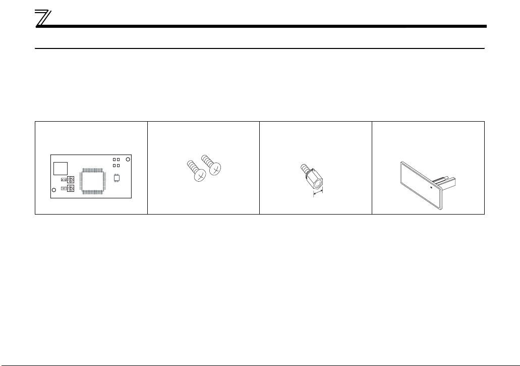
1.2.1 Product confirmation
Check the enclosed items.
Plug-in option
.........................................1
Mounting screw (M3 × 6mm)
............ 2 (Refer to page 14.)
Hex-head screw for option
mounting (5.5mm)
............. 1 (Refer to page 14.)
5.5mm
Communication option LED
display cover
............ 1 (Refer to page 13.)
2
PRE-OPERATION INSTRUCTIONS
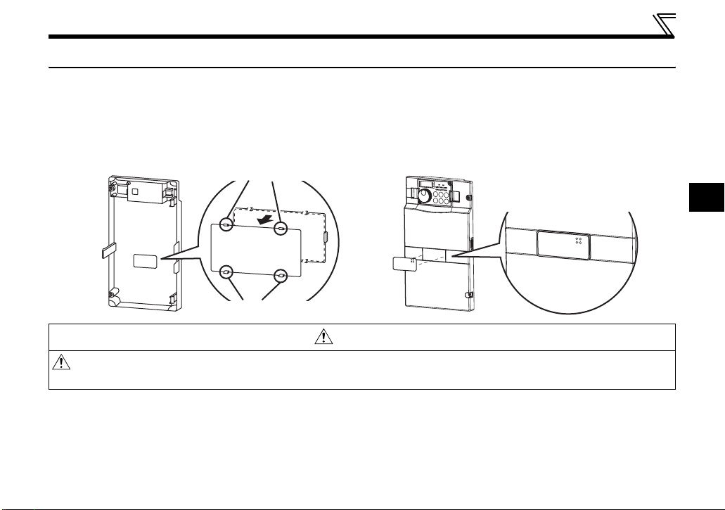
1.2.2 SERIAL number check
The plug-in option is compatible with the inverter having the following SERIAL number or later.
Check the SERIAL number indicated on the inverter rating plate or package.
z SERIAL number check
Refer to the inverter manual for the location of the rating plate.
Rating plate example
Symbol Year Month Control number
The SERIAL consists of one symbol, two characters indicating production year and month, and six characters indicating control number.
The last digit of the production year is indicated as the Year, and the Month is indicated by 1 to 9, X (October), Y (November), or Z (December.)
(1) PU/NET operation switchover (X65 signal) specification
The inverters with the following SERIAL are operated in the PU/NET operation switchover (X65 signal)
specification when connected with FR-A7NF.
z FR-A700 series
FR-A720-(-NA),
FR-A740FR-CA70-EC, FR-CA70-ECT
z FR-F700 series Japanese specification
FR-F720-0.75K to 110K,
FR-F740-0.75K to 560K
Regardless of their SERIAL numbers, all FR-F700P series inverters are operated with the PU operation interlock
(X12 signal) specification.
{ { {{{{{{
TC{{{A{{{G{{ TC number
Model SERIAL number
(-NA)(-EC)(-CHT),
Model SERIAL number
7X{{{{{{ to
03{{{{{{
91{{{{{{ or later
SERIAL
1
3

PRE-OPERATION INSTRUCTIONS
z FR-F700 series NA specification
Model SERIAL number
FR-F720-00046 to 04750-NA,
FR-F740-00023 to 12120-NA
z FR-F700 series EC specification
Model SERIAL number
FR-F740-00023 to 00620-EC,
FR-CF70-EC, FR-CF70-ECT
z FR-F700 series CHT specification
Model SERIAL number
FR-F740-0.75K to 55K-CHT,
FR-F740-S75K to S630K-CHT
91{{{{{{ or later
95{{{{{{ or later
93{{{{{{ or later
4
PRE-OPERATION INSTRUCTIONS
(2) PU operation interlock (X12 signal) specification
The FR-F700P series and the inverters with the following TC and SERIAL numbers are operated in the PU
operation interlock (X12 signal) specification when connected with FR-A7NF.
z FR-A700 series Japanese and NA specification
Model SERIAL number
FR-A720- (-NA)
FR-A740-
(-NA)
04{{{{{{
z FR-A700 series EC specification
Model TC number SERIAL number
FR-A740-00023 to 00052-EC
FR-A740-00083/00126-EC
FR-A740-00170/00250-EC
FR-A740-00310/00380-EC
FR-A740-00470/00620-EC
FR-CA70-EC
(Control unit)
FR-CA70-ECT
(Control unit)
TC{{{A{{{G7{ C0{{{{{{{ or later
TC{{{A{{{G8{ A0{{{{{{{ or later
TC{{{A{{{G7{ C0{{{{{{{ or later
TC{{{A{{{G8{ B0{{{{{{{ or later
TC{{{A{{{G7{ Y0{{{{{{{ or later
TC{{{A{{{G8{ Z0{{{{{{{ or later
TC{{{A{{{G7{ Z0{{{{{{{ or later
TC{{{A{{{G8{ B0{{{{{{{ or later
TC{{{A{{{G7{ Y0{{{{{{{ or later
TC{{{A{{{G8{ Z0{{{{{{{ or later
TC{{{A{{{G7{ V0{{
TC{{{A{{{G8{ E0{{{{{{{ or later
TC{{{A{{{G7{ S0{{{{{{{ or later
TC{{{A{{{G8{ E0{{{{{{{ or later
{{{{{ or later
1
5

PRE-OPERATION INSTRUCTIONS
z FR-A700 series CHT specification
Model TC number SERIAL number
FR-A740-0.4K to 1.5K-CHT
FR-A740-2.2K/3.7K-CHT
FR-A740-5.5K/7.5K-CHT
FR-A740-11K/15K-CHT
FR-A740-18.5/22K-CHT
FR-A740-30K to 45K-CHT
FR-A740-55K-CHT
FR-A740-75K/90K-CHT
FR-A740-110K-CHT
FR-A740-132K-CHT
FR-A740-160K/185K-CHT TC{{{A{{{G7{ W0{{{{{{{ or later
FR-A740-220K to 280K-CHT TC{{{A{{{G7{ V0{{
FR-A740-315K/355K-CHT TC{{{A{{{G7{ U0{{{{{{{ or later
FR-A740-400K to 500K-CHT TC{{{A{{{G7{ R0{{{{{{{ or later
TC{{{A{{{G7{ A0{{{{{{{ or later
TC{{{A{{{G8{ Y0{{{{{{{ or later
TC{{{A{{{G7{ A0{{{{{{{ or later
TC{{{A{{{G8{ Z0{{{{{{{ or later
TC{{{A{{{G7{ W0{{{{{{{ or later
TC{{{A{{{G8{ X0{{{{{{{ or later
TC{{{A{{{G7{ X0{{{{{{{ or later
TC{{{A{{{G8{ Z0{{{{{{{ or later
TC{{{A{{{G7{ W0{{{{{{{ or later
TC{{{A{{{G8{ X0{{{{{{{ or later
TC{{{A{{{G7{ X0{{
TC{{{A{{{G8{ V0{{{{{{{ or later
TC{{{A{{{G7{ W0{{{{{{{ or later
TC{{{A{{{G8{ V0{{{{{{{ or later
TC{{{A{{{G7{ V0{{{{{{{ or later
TC{{{A{{{G8{ F0{{{{{{{ or later
TC{{{A{{{G7{ X0{{{{{{{ or later
TC{{{A{{{G8{ G0{{{{{{{ or later
TC{{{A{{{G7{ W0{{{{{{{ or later
TC{{{A{{{G8{ G0{{{{{{{ or later
{{{{{ or later
{{{{{ or later
6
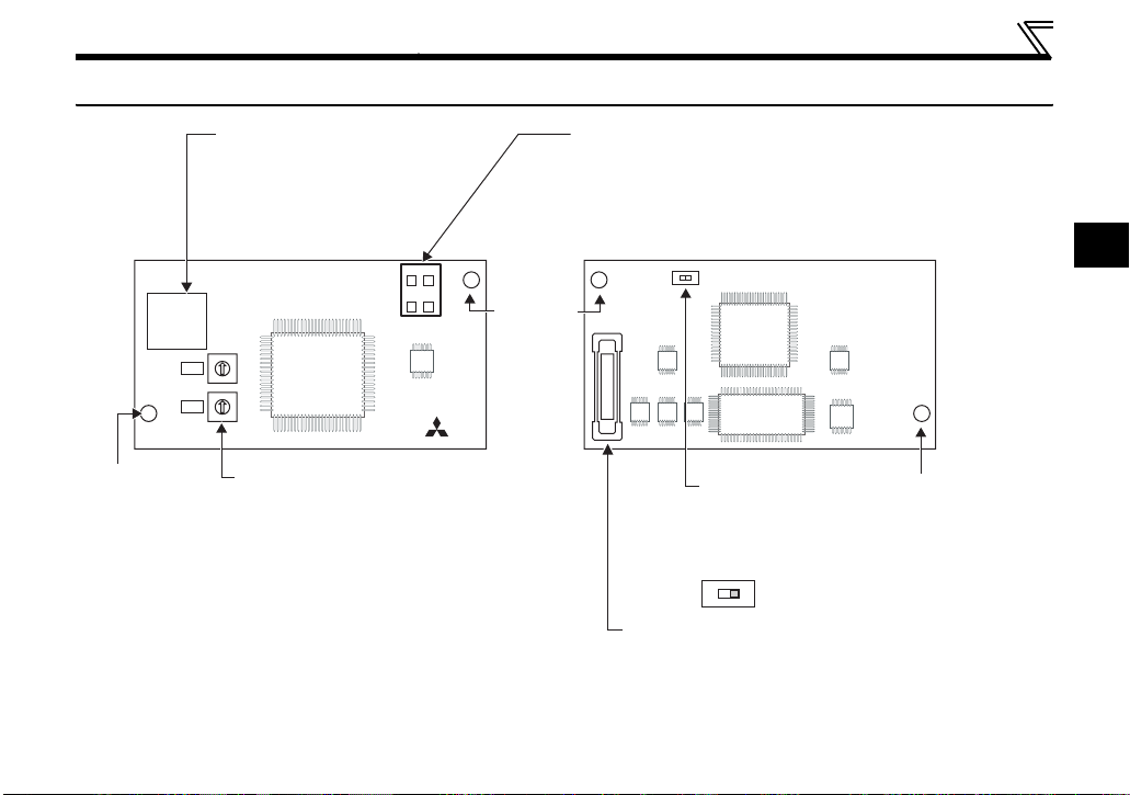
1.3 Parts
PRE-OPERATION INSTRUCTIONS
FR-A7NF
Mounting
hole
Connector for communication
Connect to the network by
connecting a FL-net dedicated
LED (operation status indication)
Lit/flicker/OFF of the LED indicate inverter
operation status.
cable.
Front view Rear view
D1 D2
SW2
0
1
9
2
8
3
X10
7
4
6
5
0
1
9
2
8
3
X1
7
4
6
5
SW1
Node address switch
Set the node address.
(Refer to page 16)
D3 D4
Mounting
hole
Connector
Connect to the inverter option connector.
(Refer to page 8)
SW3
Switch for manufacturer
setting
Do not change from
initially-set status (OFF).
SW3
N
2
L
O
1
Mounting
hole
7
PRE-OPERATION INSTRUCTIONS
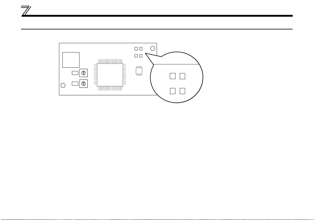
D1 D2
S
D3 D4
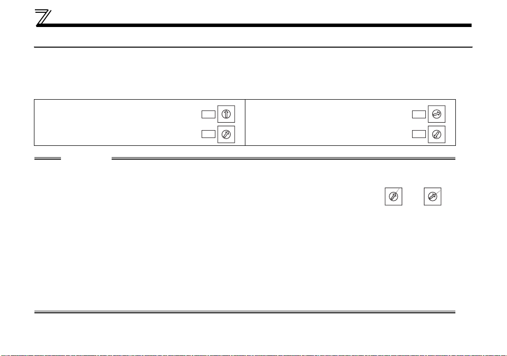
1.4 LED status
Each LED indicates the operating status of the option unit and network according to the indication status.
D1 D2
D3 D4
SW2
0
1
9
2
8
3
X10
7
4
6
5
0
1
9
2
8
3
X1
7
4
6
5
SW1
FR-A7NF
D1: Communication set status LED (CHG)
D2: Device status LED (DEV)
D3: Reception/transmission LED (TX/RX)
D4: Remote status LED (RMT)
8

PRE-OPERATION INSTRUCTIONS
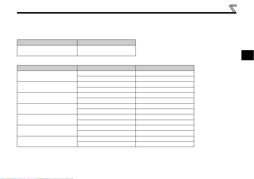
1.4.1 Device status LED (DEV), remote status LED (RMT)
LED Status
DEV RMT
Node Status Description
Power is OFF The inverter power is OFF.
· Node address is out of range (other than 1 to 64).
· Optional board fault
· When mounted to the inverter which is not compatible with
Hardware fault
FL remote network is not connected
FL remote network at a remote stop
FL remote network
during remote connection
processing
Master is not present When the master is disconnected from FL remote network.
FL remote network
during remote operation
Own node is disconnected When the own node is disconnected from FL remote network.
the FR-A7NF (Refer to page 3 for the inverter which is
compatible with the FR-A7NF)
· When a contact fault occurs in an option connector between
the inverter and communication option.
Although hardware is normal, it is not connected to the FL
remote network.
It is correctly set to connect to the FL remote network and
waiting for remote I/O control.
Although remote I/O control started, initial processing is in
progress.
During remote I/O control
1
9
PRE-OPERATION INSTRUCTIONS
LED Status
DEV RMT
Node Status Description
Setting error
Duplicate node When node address is duplicate with other node address
Although it is connected to the FL remote, setting error is found.
(When the slave is not the one the master is expected.)
:OFF, : red is lit, : green is lit, :red is flickering, : green is flickering,
: red and green are alternately flickering
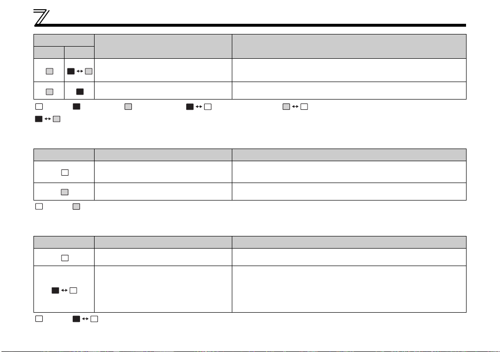
1.4.2 Transmitting (TX)/receiving (RX) LED
LED Status Node Status Description
Not transmitting (TX)/not receiving
(RX)
Transmitting (TX)/receiving (RX) Flickers at high speed during continuous transmitting/receiving
———
:OFF, : green is lit
1.4.3 Communication set status LED (CHG)
LED Status Node Status Description
Communication setting is not changed
Communication setting is changed
:OFF, : red is flickering
The red LED flickers when the applied setting and the node
address switch setting differ. The setting value of the node
address switch is applied by re-powering ON the inverter in this
status, then communication setting status LED turns OFF.
———
10

PRE-OPERATION INSTRUCTIONS
1.5 Specifications
1.5.1 Inverter option specifications
Power supply Supplied from the inverter
Typ e Inverter plug-in option (can be mounted/dismounted to/from the inverter front face)
FL-net dedicated cable Refer to page 18
1.5.2 Communication specifications
Maximum number of
connectable inverters
Communication speed Auto negotiation (auto detection) (10Mbps/100Mbps)
Topology
Communication
distance
Electrical interface Conforms to IEEE802.3u (conforms to CSMA/CD)
Transmission protocol FL remote
Node address setting
I/O points Input 64 points, output 64 points
64 units maximum
· Star (connection with a hub in the center)
· Star bus (connection with multiple hubs)
· Between node ⇔ hub: 100m maximum (Node indicate master and inverters.)
· Between hubs: 100m maximum
· Overall length: 2000m maximum
Can be set with node address switch (Refer to page 16).
The setting is applied to IP address as well.
(192.168.250.node address)
1
11
2 INSTALLATION
2.1 Pre-installation instructions
Make sure that the input power of the inverter is OFF.
CAUTION
With input power ON, do not install or remove the plug-in option. Otherwise, the inverter and
plug-in option may be damaged.
Static electricity in your body must be discharged before you touch the product. Otherwise the
product may be damaged.
12
INSTALLATION
2.2 Installation of the communication option LED display cover
Mount the cover for displaying the operation status indication LED for the communication option on the
inverter front cover.
1)
Cut off hooks on the rear of the inverter front
cover with nipper, etc. and open a window for
fitting the LED display cover.
Cut off with a nipper, etc.
2)
Fit the communication option LED display
cover to the front of the inverter front cover
and push it into until fixed with hooks.
Fit it so that the position of
lenses is in the upper-right
of the LED display cover.
Fitting drawing
Cut off with a nipper, etc.
CAUTION
Take caution not to hurt your hand and such with portions left by cutting hooks of the rear of
the front cover.
2
13
INSTALLATION
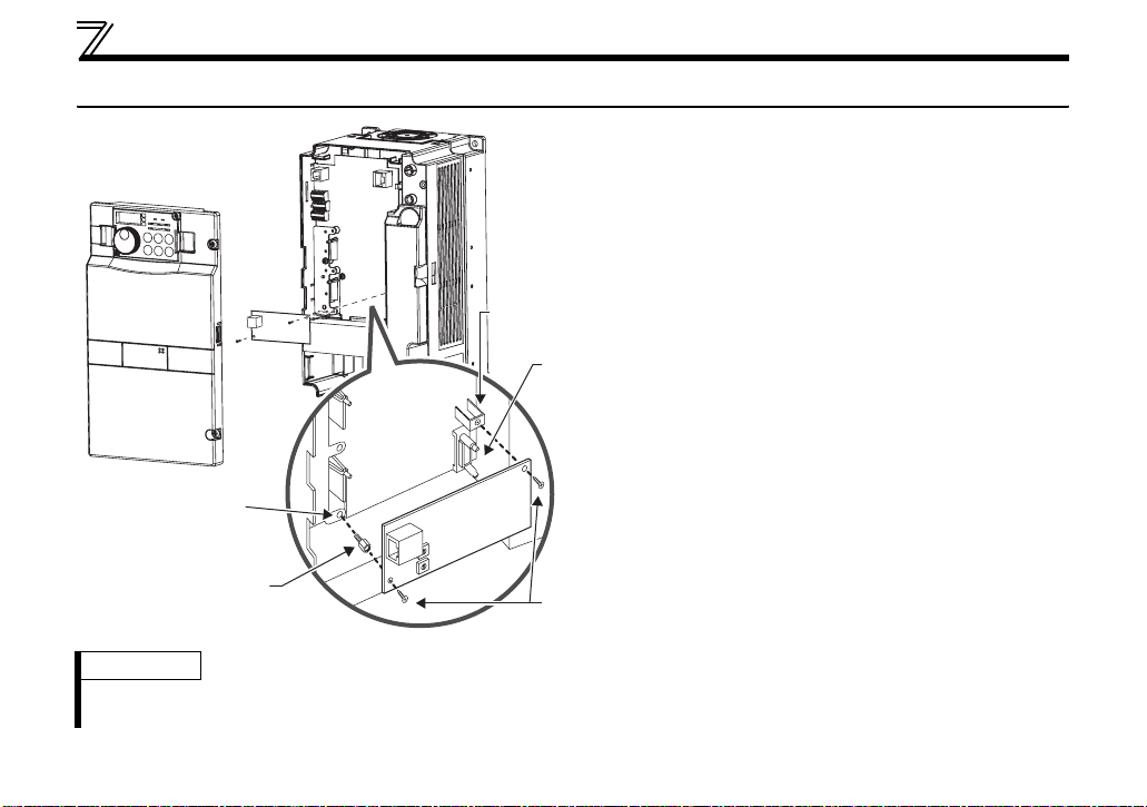
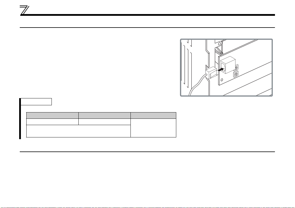
2.3 Installation procedure
1) Remove the inverter front cover.
1)
2) Mount the hex-head screw for option
mounting into the inverter screw hole
(on earth plate) (size 5.5mm, tightening
torque 0.56Nxm to 0.75Nxm).
Screw hole for
option mounting
Inverter side
option
connector
3) Securely fit the connector of the plug-in
option to the inverter connector along
the guides.
4) Securely fix the both right and left sides
of the plug-in option to the inverter with
the accessory mounting screws.
(Tightening torque 0.33Nxm to
0.40Nxm)
If the screw holes do not line up, the
connector may not have been plugged
securely. Check for loose plugging.
Screw hole for
option mounting
(on earth plate)
Hex-head screw
for option mounting
2)
3)
1
2
0
3
9
4
8
5
7
6
1
2
0
3
9
4
8
5
7
6
4)
Mounting
screws
REMARKS
• Remove a plug-in option after removing two screws on both left and right sides.
(The plug-in option is easily removed if the control circuit terminal block is removed before.)
14
INSTALLATION
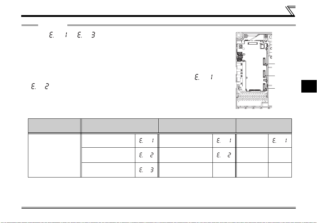
CAUTION
• One of " to " (option fault) appears when the inverter cannot rec-
ognize the option because it is improperly mounted, etc. One of the faults also
appears when an incompatible option is mounted to the inverter. Different indication will appear according to the mounted position (connector 1, 2, or 3).
• For an inverter having several option connectors, use the bottom connector to
mount the option.
If it is connected to a connector other than the bottom connector, " " or
" " (option fault) will appear and its operation will be disabled. Different
indication will appear according to the mounted position (connector 1 or 2).
• The number of option connectors differs by the model. The table below shows
how the fault indication differs according to the number of connectors and their
positions.
Number of option
connectors
Mounting position
and fault indication
3 2 1
Connector 1
(top connector)
Connector 2
(middle connector)
Connector 3
(bottom connector)
Connector 1
(top connector)
Connector 2
(bottom connector)
⎯⎯⎯⎯
Example of FR-A700
Connector 1
⎯⎯
(Refer to Chapter 1 of the inverter's Instruction Manual for the number of option connectors.
• Take caution not to drop a hex-head screw for option mounting or mounting screw during mounting and
removal.
• Pull out the option straight to remove. Otherwise, the connector may be damaged.
Connector 1
Connector 2
Connector 3
2
15
INSTALLATION
2.4 Node address setting
Set the node address between "1 to 64" using node address switches on the FR-A7NF (Refer to page 7).
The setting is applied when the power turns OFF once, then ON again.
Set the arrow (×) of the corresponding switches to the number to set a desired address.
z Setting example
Node address 1:
Set the "×" of X10(SW1) to "0" and the
X10
"×" of X1(SW2) to "1".
X1
CAUTION
• Set the node address switch to the switch number position correctly. If the switch
is set between numbers, normal data communication can not be established.
• If the node address switch is set to a value other than "1 to 64", it is invalid due to outside of setting
range. In this case, DEV LED of the option is lit red and E.OPT appears on the operation panel of the
inverter.
• You cannot set the same node address to other devices on the network. (Doing so disables proper
communication.)
• Set the inverter node address before switching ON the inverter and do not change the setting while
power is ON. Otherwise you may get an electric shock.
• Changes in the node address setting are applied only at the next power-ON. Therefore, if the node
address setting is changed, make sure to power OFF and ON the inverter power.
Node address 26:
0
1
9
2
8
3
7
4
Set the "×" of X10(SW1) to "2" and the
6
5
"×" of X1(SW2) to "6".
0
1
9
2
8
3
7
4
6
5
Good
example
0
1
9
2
8
3
7
4
6
5
X10
X1
Bad
example
9
8
7
6
0
1
9
2
8
3
7
4
6
5
0
1
9
2
8
3
7
4
6
5
0
1
2
3
4
5
16
3 WIRING
3.1 Connection to network
(1) Be sure to check the following before connecting the inverter to the network.
· Check that the FR-A7NF is correctly mounted to the inverter. (Refer to page 14)
· Check that the correct node address is set. (Refer to page 16)
· Check that the FL-net dedicated cable is correctly connected to the FR-A7NF. (Refer to page 18)
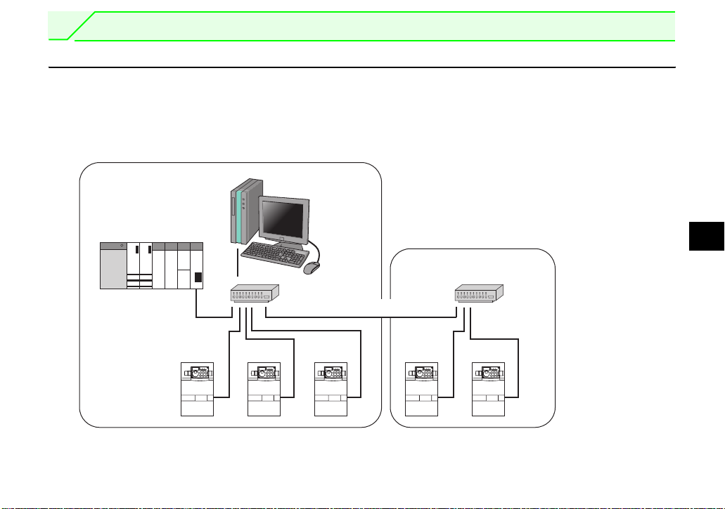
(2) System configuration
Segment 1
Master
100m maximum)
(
Personal computer
Segment 2
Hub
Cascade connection (100m maximum)
Inverter Inverter Inverter Inverter Inverter
Overall length: 2000m maximum
3
Hub
17
WIRING
3.2 Cable specifications
Connect the FR-A7NF option unit to the FL remote network using the FL-net dedicated cable below.
Cables : TPCC5 or more (Twisted Pair Communication Cable
for LAN Category 5)
For the shape, use STP (Shielded Twisted Pair)
(according to the 100BASE-TX(IEEE802.3u)
standard)
Maximum wiring length:100m maximum between hub and inverter.
(according to the 100BASE-TX
(IEEE802.3u) standard)
REMARKS
y FL-net dedicated cable...recommended product (as of July 2011)
Typ e Cable Length (m) Maker
FLG-S-{{{ 1m to 100m
(Example: when the cable length is 1m)
FLG-S-010
Shinwa Co., Ltd.
3.3 Precautions for system configuration
Enough safety measures are necessary when installing the FL-net dedicated cable and connecting to the
FL remote network.
Consult the network provider and network administrator (person in charge of network planning and IP
address management) including terminal treatment of connection cable, construction of trunk cable, etc.
We are not responsible for system troubles from connecting to the FL remote network.
18
WIRING
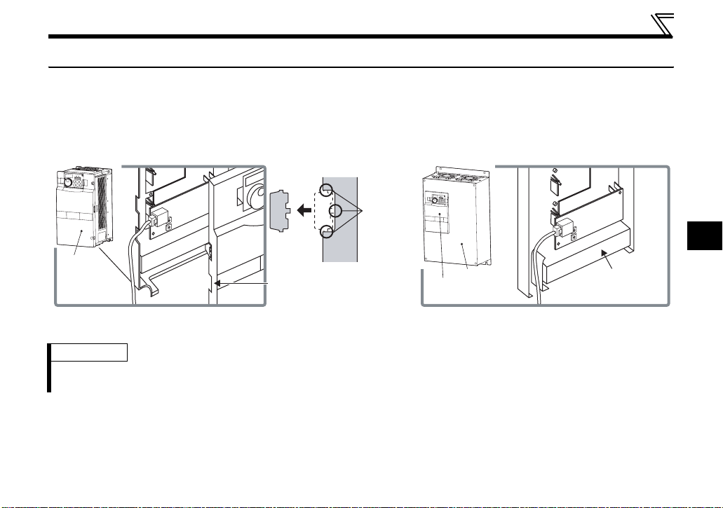
3.4 Wiring
For wiring of the inverter which has one front cover, route wires between the control circuit terminal block
and front cover. If cables can not be routed between the control circuit terminal block and front cover (about
7mm), remove a hook of the front cover and use a space become available.
For wiring of the inverter which has front cover 1 and 2, use the space on the left side of the control circuit
terminal block.
Cut off
1
2
0
3
9
4
8
5
7
6
1
2
0
3
9
4
8
5
7
6
Front cover
Cut off a hook on the inverter
front cover side surface.
(Cut off so that no portion is left.)
Inverter which has one front cover Inverter which has front cover 1 and 2
REMARKS
⋅ When the hook of the inverter front cover is cut off for wiring, the protective structure (JEM1030) changes to open
type (IP00).
with a
nipper,
etc.
Front cover 1
Front cover 2
1
2
0
3
9
4
8
5
7
6
1
2
0
3
9
4
8
5
7
6
Control circuit
terminal block
3
19
WIRING
C
AUTION
Do not connect the parameter unit (FR-PU07, etc.) to the FR-A7NF communication connector.
Doing so will damage the option.
When performing wiring using the space between the inverter front cover and control circuit
terminal block, take care not to subject the cable to stress.
After wiring, wire offcuts must not be left in the inverter. They may cause an error, failure or
malfunction.
20

4 INVERTER SETTING
4.1 Parameter list
zThe following parameters are used for the communication option (FR-A7NF)
Parameter
Number
37 Speed display 0, 1 to 9998 1 0 37
144 Speed setting switchover
501
*
* Parameters which can be displayed when the plug-in option (FR-A7NF) is mounted.
Communication error occurrence
count display
Name Setting Range
0, 2, 4, 6, 8, 10, 102,
104, 106, 108, 110
01032
Minimum
Setting
Increments
1437
Initial
Value
Refer to
Page
4
21

INVERTER SETTING
zParameters whose functions are always the same
When the FR-A7NF is mounted to the inverter, following parameter functions are always the same.
(Changed setting is invalid even if the setting value is changed.)
Parameter
Number
79 Operation mode selection
180 RL terminal function selection 0 Low-speed operation command
181 RM terminal function selection 1 Middle-speed operation command
182 RH terminal function selection 2 High-speed operation command
183 RT terminal function selection 3 Second function selection
184 AU terminal function selection 9999 — (no function)
185 JOG terminal function selection 9999 — (no function)
186 CS terminal function selection 9999 — (no function)
187 MRS terminal function selection 24 Output stop
188 STOP terminal function selection 9999 — (no function)
189 RES terminal function selection
190 RUN terminal function selection 0 Inverter running
191 SU terminal function selection 1 Up to frequency
192 IPF terminal function selection 2 Instantaneous power failure/undervoltage
193 OL terminal function selection 3 Overload alarm
194 FU terminal function selection 4 Output frequency detection
195 ABC1 terminal function selection 99 Fault output
196 ABC2 terminal function selection 9999 — (no function)
338
339
Communication operation
command source
Communication speed command
source
Name Setting
*3 Network operation mode 25
0
7
*4 PU operation interlock 25
*3 PU/NET operation switchover
65
12 *4 PU operation interlock
0 Operation command source communication 30
0 Speed command source communication 30
Function
Refer
to Page
— *2
— *2
— *2
— *2
— *2
— *2
— *2
— *2
— *2
— *2
— *2
— *2
— *2
— *2
— *2
— *2
— *2
— *2
22

INVERTER SETTING
Parameter
Number
340
342
500 *1
502 *1
550
551
*1 Parameters which can be displayed when the plug-in option (FR-A7NF) is mounted.
*2 Refer to the inverter manual for details.
*3 This setting is for the inverters with the PU/NET operation switchover (X65 signal) specification.
*4 This setting is for the inverters with the PU operation interlock (X12 signal) specification. (Refer to page 5)
The X12 signal is valid only when it is input via FL remote communication. (Refer to page 50) (It is invalid when input
from a control circuit terminal of the inverter.)
Communication startup mode
selection
Communication EEPROM write
selection
Communication error execution
waiting time
Stop mode selection at
communication error
NET mode operation command
source selection
PU mode operation command
source selection
Name Setting
10
0
0
1
9999
2
Function
Started in Network operation mode. Operation
mode can be changed between the PU
operation mode and Network operation mode
from the operation panel.
Parameter values written by communication are
written to the EEPROM and RAM.
There is no waiting time since the communication
line fault occurrence until communication error
(0s). Note that actual time depends on the
detection time on FL remote network.
The inverter decelerates to stop at
communication fault occurrence, when provide
a fault output.
Automatic communication option recognition
Normally, control source of the RS-485 terminal
is valid. When a communication option is
mounted, the control source of the
communication option is valid.
Selects the PU connector as the PU operation
mode operation source.
(Refer to page 3)
Refer
to Page
25
— *2
— *2
33
4
— *2
— *2
23

INVERTER SETTING
4.2 Operation mode setting
Powering ON the inverter with the communication option (FR-A7NF) mounted starts the inverter in Network
operation mode.
(1) Network operation [NET] ... Controls the inverter with instructions from the network via the
communication option.
Functions of Pr.79 and Pr.340 are always the same when the FR-A7NF is
mounted.
(2) PU operation [PU].............. Controls the inverter from the key of the operation panel (FR-DU07)
mounted on the inverter or parameter unit (FR-PU07/FR-PU04).
(3) External operation [EXT] ...Controls the inverter by switching ON/OFF external signals connected to
the control circuit terminals of the inverter.
(The operation mode can not be changed to External operation mode when
the FR-A7NF is mounted.)
4.2.1 Operation mode indication
FR-DU07
Operation mode indication
(The inverter operates according to the LED lit mode.)
PU: PU operation mode
EXT: External operation mode
NET: Network operation mode *2
*1 The operation mode can not be changed to External operation mode when the FR-A7NF is mounted.
*2 "NET" is displayed when the FR-A7NF is mounted.
*1
24
 Loading...