

INVERTER
FR-F700P
INSTRUCTION MANUAL (Applied)
FR-F720P-0.75K to 110K
FR-F740P-0.75K to 560K
OUTLINE
WIRING
PRECAUTIONS FOR USE
OF THE INVERTER
PARAMETERS
PROTECTIVE FUNCTIONS
1
2
3
4
5
PRECAUTIONS FOR
MAINTENANCE AND INSPECTION
SPECIFICATIONS
6
7
Thank you for choosing this Mitsubishi Inverter.
This Instruction Manual (Applied) provides instructions for advanced use of the FR-F700P series inverters.
Incorrect handling might cause an unexpected fault. Before using the inverter, always read this Instruction Manual and the Instruction Manual
(Basic) [IB-0600411ENG] packed with the product carefully to use the equipment to its optimum.
This section is specifically about safety matters
Do not attempt to install, operate, maintain or inspect the inverter
until you have read through Instruction Manual (Basic) and
appended documents carefully and can use the equipment
correctly. Do not use the inverter until you have a full knowledge of
the equipment, safety information and instructions. In this
Instruction Manual, the safety instruction levels are classified into
"WARNING" and "CAUTION".
WARNING
CAUTION
Incorrect handling may cause hazardous
conditions, resulting in death or severe injury.
Incorrect handling may cause hazardous
conditions, resulting in medium or slight
injury, or may cause only material damage.
CAUTION
The level may even lead to a serious consequence
according to conditions. Both instruction levels must be followed
because these are important to personal safety.
1.Electric Shock Prevention
WARNING
• While power is ON or when the inverter is running, do not open
the front cover. Otherwise you may get an electric shock.
• Do not run the inverter with the front cover or wiring cover removed.
Otherwise you may access the exposed high-voltage terminals or
the charging part of the circuitry and get an electric shock.
• Even if power is OFF, do not remove the front cover except for
wiring or periodic inspection. You may accidentally touch the
charged inverter circuits and get an electric shock.
• Before wiring, inspection or switching EMC filter ON/OFF
connector, power must be switched OFF. To confirm that, LED
indication of the operation panel must be checked. (It must be
OFF.) Any person who is involved in wiring, inspection or
switching EMC filter ON/OFF connector shall wait for at least 10
minutes after the power supply has been switched OFF and
check that there are no residual voltage using a tester or the like.
The capacitor is charged with high voltage for some time after
power OFF, and it is dangerous.
• This inverter must be earthed (grounded). Earthing (grounding)
must conform to the requirements of national and local safety
regulations and electrical code (NEC section 250, IEC 536 class
1 and other applicable standards). A neutral-point earthed
(grounded) power supply for 400V class inverter in compliance
with EN standard must be used.
• Any person who is involved in wiring or inspection of this
equipment shall be fully competent to do the work.
• The inverter must be installed before wiring. Otherwise you may
get an electric shock or be injured.
• Setting dial and key operations must be performed with dry
hands to prevent an electric shock. Otherwise you may get an
electric shock.
• Do not subject the cables to scratches, excessive stress, heavy
loads or pinching. Otherwise you may get an electric shock.
• Do not replace the cooling fan while power is ON. It is
dangerous to replace the cooling fan while power is ON.
• Do not touch the printed circuit board or handle the cables with
wet hands. Otherwise you may get an electric shock.
• When measuring the main circuit capacitor capacity (Pr. 259 Main
circuit capacitor life measuring = "1"), the DC voltage is applied to
the motor for 1s at powering OFF. Never touch the motor terminal,
etc. right after powering OFF to prevent an electric shock.
• IPM motor is a synchronous motor with high-performance
magnets embedded in the rotor. Motor terminals hold highvoltage while the motor is running even after the inverter power
is turned OFF. Before wiring or inspection, the motor must be
confirmed to be stopped. When the motor is driven by the load in
applications such as fan and blower, a low-voltage manual
contactor must be connected at the inverter's output side, and
wiring and inspection must be performed while the contactor is
open. Otherwise you may get an electric shock.
2. Fire Prevention
CAUTION
• Inverter must be installed on a nonflammable wall without holes
(so that nobody touches the inverter heatsink on the rear side,
etc.). Mounting it to or near flammable material can cause a fire.
• If the inverter has become faulty, the inverter power must be
switched OFF. A continuous flow of large current could cause a
fire.
• Do not connect a resistor directly to the DC terminals P/+ and N/
-. Doing so could cause a fire.
3. Injury Prevention
CAUTION
• The voltage applied to each terminal must be the ones specified
in the Instruction Manual. Otherwise burst, damage, etc. may
occur.
• The cables must be connected to the correct terminals.
Otherwise burst, damage, etc. may occur.
• Polarity must be correct. Otherwise burst, damage, etc. may
occur.
• While power is ON or for some time after power-OFF, do not
touch the inverter since the inverter will be extremely hot. Doing
so can cause burns.
4. Additional Instructions
Also the following points must be noted to prevent an accidental failure, injury,
electric shock, etc.
(1) Transportation and installation
CAUTION
• The product must be transported in correct method that
corresponds to the weight. Failure to do so may lead to injuries.
• Do not stack the boxes containing inverters higher than the
number recommended.
• The product must be installed to the position where withstands
the weight of the product according to the information in the
Instruction Manual.
• Do not install or operate the inverter if it is damaged or has parts
missing. This can result in breakdowns.
• When carrying the inverter, do not hold it by the front cover or
setting dial; it may fall off or fail.
• Do not stand or rest heavy objects on the product.
• The inverter mounting orientation must be correct.
• Foreign conductive objects must be prevented from entering the
inverter. That includes screws and metal fragments or other
flammable substance such as oil.
• As the inverter is a precision instrument, do not drop or subject it
to impact.
• The inverter must be used under the following environment:
Otherwise the inverter may be damaged.
Surrounding air
temperature
Ambient humidity 90% RH or less (non-condensing)
Storage temperature -20°C to +65°C
Atmosphere
Environment
Altitude, vibration
*1 Temperature applicable for a short time, e.g. in transit.
*2 2.9m/s
2
or less for the 185K or higher.
-10°C to +50°C (non-freezing)
Indoors (free from corrosive gas, flammable
gas, oil mist, dust and dirt)
Maximum 1000m above sea level for
standard operation. 5.9m/s
to 55Hz (directions of X, Y, Z axes)
*1
2
*2 or less at 10
A-1
(2) Wiring
• Do not install a power factor correction capacitor, surge
suppressor or capacitor type filter on the inverter output side.
These devices on the inverter output side may be overheated or
burn out.
• The connection orientation of the output cables U, V, W to the
motor affects the rotation direction of the motor.
• IPM motor terminals (U, V, W) hold high-voltage while the IPM
motor is running even after the power is turned OFF. Before
wiring, the IPM motor must be confirmed to be stopped.
Otherwise you may get an electric shock.
• Never connect an IPM motor to the commercial power supply.
Applying the commercial power supply to input terminals (U,V,
W) of an IPM motor will burn the IPM motor. The IPM motor must
be connected with the output terminals (U, V, W) of the inverter.
(3) Test operation and adjustment
• Before starting operation, each parameter must be confirmed
and adjusted. A failure to do so may cause some machines to
make unexpected motions.
(4) Operation
• The IPM motor capacity must be same with the inverter capacity.
(The 0.75K inverter can be used with a one-rank lower MM-EF
motor.)
• Do not use multiple IPM motors with one inverter.
• Any person must stay away from the equipment when the retry
function is set as it will restart suddenly after trip.
• Since pressing key may not stop output depending on the
function setting status, separate circuit and switch that make an
emergency stop (power OFF, mechanical brake operation for
emergency stop, etc.) must be provided.
• OFF status of the start signal must be confirmed before resetting
the inverter fault. Resetting inverter alarm with the start signal
ON restarts the motor suddenly.
• Do not use an IPM motor in an application where a motor is
driven by its load and runs at a speed higher than the maximum
motor speed.
• A dedicated IPM motor must be used under IPM motor control.
Do not use a synchronous motor, induction motor, or
synchronous induction motor under IPM motor control.
• The inverter must be used for three-phase induction motors or
the dedicated IPM motor.
Connection of any other electrical equipment to the inverter
output may damage the equipment.
• Do not modify the equipment.
• Do not perform parts removal which is not instructed in this
manual. Doing so may lead to fault or damage of the inverter.
CAUTION
CAUTION
WARNING
CAUTION
• The electronic thermal relay function does not guarantee
protection of the motor from overheating. It is recommended to
install both an external thermal and PTC thermistor for overheat
protection.
• Do not use a magnetic contactor on the inverter input for
frequent starting/stopping of the inverter. Otherwise the life of
the inverter decreases.
• The effect of electromagnetic interference must be reduced by
using a noise filter or by other means. Otherwise nearby
electronic equipment may be affected.
• Appropriate measures must be taken to suppress harmonics.
Otherwise power supply harmonics from the inverter may heat/
damage the power factor correction capacitor and generator.
• When driving a 400V class motor by the inverter, the motor must
be an insulation-enhanced motor or measures must be taken to
suppress surge voltage. Surge voltage attributable to the wiring
constants may occur at the motor terminals, deteriorating the
insulation of the motor.
• When parameter clear or all parameter clear is performed, the
required parameters must be set again before starting
operations because all parameters return to the initial value.
• The inverter can be easily set for high-speed operation. Before
changing its setting, the performances of the motor and machine
must be fully examined.
• Stop status cannot be hold by the inverter's brake function. In
addition to the inverter's brake function, a holding device must
be installed to ensure safety.
• Before running an inverter which had been stored for a long
period, inspection and test operation must be performed.
• For prevention of damage due to static electricity, nearby metal
must be touched before touching this product to eliminate static
electricity from your body.
• Do not connect an IPM motor under the general-purpose motor
control settings (initial settings). Do not use a general-purpose
motor under the IPM motor control settings. Doing so will cause
a failure.
• In the system with an IPM motor, the inverter power must be
turned ON before closing the contacts of the contactor at the
output side.
(5) Emergency stop
• A safety backup such as an emergency brake must be provided
to prevent hazardous condition to the machine and equipment in
case of inverter failure.
• When the breaker on the inverter input side trips, the wiring must
be checked for fault (short circuit), and internal parts of the
inverter for a damage, etc. The cause of the trip must be
identified and removed before turning ON the power of the
breaker.
• When any protective function is activated, appropriate corrective
action must be taken, and the inverter must be reset before
resuming operation.
CAUTION
A-2
(6) Maintenance, inspection and parts replacement
CAUTION
• Do not carry out a megger (insulation resistance) test on the
control circuit of the inverter. It will cause a failure.
(7) Disposing of the inverter
CAUTION
• The inverter must be treated as industrial waste.
General instructions
Many of the diagrams and drawings in this Instruction Manual
show the inverter without a cover or partially open for explanation.
Never operate the inverter in this manner. The cover must be
always reinstalled and the instruction in this Instruction Manual
must be followed when operating the inverter.
For more details on a dedicated IPM motor, refer to the Instruction
Manual of the dedicated IPM motor.

CONTENTS
1 OUTLINE 1
1.1 Product checking and parts identification ........................................................2
1.2 Inverter and peripheral devices..........................................................................3
1.2.1 Peripheral devices ..................................................................................................................... 4
1.3 Method of removal and reinstallation of the front cover.................................. 6
1.4 Installation of the inverter and enclosure design ............................................. 8
1.4.1 Inverter installation environment................................................................................................ 8
1.4.2 Cooling system for inverter enclosure ..................................................................................... 10
1.4.3 Inverter placement ................................................................................................................... 10
2 WIRING 13
2.1 Wiring.................................................................................................................. 14
2.1.1 Terminal connection diagram .................................................................................................. 14
2.1.2 EMC filter................................................................................................................................. 15
2.2 Main circuit terminal specifications ................................................................. 16
2.2.1 Specification of main circuit terminal ....................................................................................... 16
2.2.2 Terminal arrangement of the main circuit terminal, power supply and the motor wiring ......... 16
2.2.3 Cables and wiring length ......................................................................................................... 20
2.2.4 When connecting the control circuit and the main circuit separately to the power supply....... 24
CONTENTS
2.3 Control circuit specifications ........................................................................... 26
2.3.1 Control circuit terminals ........................................................................................................... 26
2.3.2 Changing the control logic ....................................................................................................... 29
2.3.3 Control circuit terminal layout .................................................................................................. 31
2.3.4 Wiring instructions ................................................................................................................... 31
2.3.5 Mounting the operation panel (FR-DU07) on the enclosure surface ....................................... 32
2.3.6 RS-485 terminal block ............................................................................................................. 33
2.3.7 Communication operation........................................................................................................ 33
2.4 Connection of stand-alone option units .......................................................... 34
2.4.1 Connection of the brake unit (FR-BU2) ................................................................................... 34
2.4.2 Connection of the brake unit (FR-BU/MT-BU5)....................................................................... 36
2.4.3 Connection of the brake unit (BU type) ................................................................................... 38
2.4.4 Connection of the high power factor converter (FR-HC/MT-HC)............................................. 38
2.4.5 Connection of the power regeneration common converter (FR-CV) (55K or lower) ................ 40
2.4.6 Connection of the power regeneration converter (MT-RC) (75K or higher) ............................ 41
2.4.7 Connection of the power factor improving DC reactor (FR-HEL) ............................................ 42
3 PRECAUTIONS FOR USE OF THE INVERTER 43
3.1 EMC and leakage currents................................................................................44
I

3.1.1 Leakage currents and countermeasures ................................................................................. 44
3.1.2 EMC measures........................................................................................................................ 46
3.1.3 Power supply harmonics ......................................................................................................... 48
3.1.4 Harmonic suppression guideline .............................................................................................49
3.2 Installation of a reactor .....................................................................................52
3.3 Power-OFF and magnetic contactor (MC) .......................................................52
3.4 Inverter-driven 400V class motor ..................................................................... 53
3.5 Precautions for use of the inverter .................................................................. 54
3.6 Failsafe of the system which uses the inverter .............................................. 56
4 PARAMETERS 59
4.1 Operation panel (FR-DU07) ............................................................................... 60
4.1.1 Component of the operation panel (FR-DU07)........................................................................ 60
4.1.2 Basic operation (factory setting) .............................................................................................. 61
4.1.3 Easy operation mode setting (easy setting mode) .................................................................. 62
4.1.4 Changing the parameter setting value..................................................................................... 63
4.1.5 Displaying the set frequency ................................................................................................... 63
4.2 Parameter list ..................................................................................................... 64
4.2.1 Parameter list .......................................................................................................................... 64
4.3 IPM motor control <IPM>.................................................................................. 77
4.3.1 Setting procedure of IPM motor control <IPM> ...................................................................... 77
4.3.2 Initializing the parameters required to drive an IPM motor (Pr.998) <IPM> ........................... 80
4.3.3 IPM motor test operation (Pr.800) <IPM> ............................................................................... 82
4.3.4 Adjusting the speed control gain (Pr.820, Pr.821) <IPM> ...................................................... 84
4.4 Adjustment of the output torque (current) of the motor ............................... 87
4.4.1 Manual torque boost (Pr. 0, Pr. 46) <V/F> ............................................................................. 87
4.4.2 Simple magnetic flux vector control (Pr.80, Pr.90) <S MFVC> .............................................. 89
4.4.3 Slip compensation (Pr. 245 to Pr. 247) <V/F><S MFVC> ...................................................... 90
4.4.4 Stall prevention operation
(Pr. 22, Pr. 23, Pr. 48, Pr. 49, Pr. 66, Pr. 148, Pr. 149, Pr. 154, Pr. 156, Pr. 157) ................. 91
4.5 Limiting the output frequency ......................................................................... 96
4.5.1 Maximum/minimum frequency (Pr. 1, Pr. 2, Pr. 18) ............................................................... 96
4.5.2 Avoiding mechanical resonance points (Frequency jump) (Pr. 31 to Pr. 36) ......................... 97
4.6 V/F pattern ......................................................................................................... 98
4.6.1 Base frequency, voltage (Pr. 3, Pr. 19, Pr. 47) <V/F><S MFVC> .......................................... 98
4.6.2 Load pattern selection (Pr. 14) <V/F> .................................................................................. 100
4.6.3 Adjustable 5 points V/F (Pr. 71, Pr. 100 to Pr. 109) <V/F>................................................... 101
4.7 Frequency setting by external terminals ...................................................... 102
II

4.7.1 Multi-speed setting operation (Pr. 4 to Pr. 6, Pr. 24 to Pr. 27, Pr. 232 to Pr. 239) ............... 102
4.7.2 Jog operation (Pr. 15, Pr. 16) ............................................................................................... 104
4.7.3 Input compensation of multi-speed and remote setting (Pr. 28) ........................................... 106
4.7.4 Remote setting function (Pr. 59) ........................................................................................... 106
4.8 Setting of acceleration/deceleration time and
acceleration/deceleration pattern.................................................................. 109
4.8.1 Setting of the acceleration and deceleration time (Pr.7, Pr.8, Pr.20, Pr.21,
Pr.44, Pr.45, Pr.147, Pr.791, Pr.792) ................................................................................... 109
4.8.2 Starting frequency and start-time hold function (Pr.13, Pr.571) <V/F><S MFVC> ............... 113
4.8.3 Minimum motor rotation frequency (Pr.13) <IPM> ............................................................... 114
4.8.4 Acceleration/deceleration pattern (Pr.29, Pr.140 to Pr.143)................................................. 115
4.9 Selection and protection of a motor ............................................................. 117
4.9.1 Motor protection from overheat (Electronic thermal relay function) (Pr. 9, Pr. 51) ............... 117
4.9.2 Applied motor (Pr. 71) .......................................................................................................... 122
4.10 Motor brake and stop operation.................................................................... 123
4.10.1 DC injection brake of general-purpose motor control (Pr. 10 to Pr. 12) <V/F><S MFVC> ... 123
4.10.2 DC injection brake of IPM motor control (Pr.10, Pr.11) <IPM>............................................. 124
4.10.3 Selection of a regenerative brake and DC feeding (Pr. 30, Pr. 70) ...................................... 125
4.10.4 Stop selection (Pr. 250) ........................................................................................................ 130
4.10.5 Output stop function (Pr.522) ............................................................................................... 131
4.11 Function assignment of external terminal and control ............................... 133
4.11.1 Input terminal function selection (Pr. 178 to Pr. 189) ........................................................... 133
4.11.2 Inverter output shutoff signal (MRS signal, Pr. 17) ............................................................... 136
4.11.3 Condition selection of function validity by the second function selection signal (RT)
(RT signal, Pr. 155) .............................................................................................................. 137
4.11.4 Start signal selection (STF, STR, STOP signal, Pr. 250) ..................................................... 138
4.11.5 Output terminal function selection (Pr. 190 to Pr. 196)......................................................... 140
4.11.6 Detection of output frequency (SU, FU, FU2 signal, Pr. 41 to Pr. 43, Pr. 50,
Pr. 870)................................................................................................................................. 144
4.11.7 Output current detection function
(Y12 signal, Y13 signal, Pr. 150 to Pr. 153, Pr. 166, Pr. 167) .............................................. 146
4.11.8 Remote output function (REM signal, Pr. 495 to Pr. 497) .................................................... 148
4.11.9 Pulse train output of output power (Y79 signal, Pr. 799) ...................................................... 149
CONTENTS
4.12 Monitor display and monitor output signal .................................................. 150
4.12.1 Speed display and speed setting (Pr. 37, Pr. 144, Pr. 505) ................................................. 150
4.12.2 DU/PU monitor display selection
(Pr. 52, Pr. 54, Pr. 158, Pr. 170, Pr. 171, Pr. 268, Pr. 563, Pr. 564, Pr. 891) ....................... 152
4.12.3 FM, AM terminal function selection (Pr.55, Pr.56, Pr.867) ................................................... 157
4.12.4 Terminal FM, AM calibration
(Calibration parameter C0 (Pr. 900), C1 (Pr. 901)) .............................................................. 159
4.12.5 How to calibrate the terminal FM when using the operation panel (FR-DU07) ..................... 161
4.13 Operation selection at power failure and instantaneous power failure..... 162
III

4.13.1 Automatic restart after instantaneous power failure/flying start under general-purpose motor
control (Pr. 57, Pr. 58, Pr. 162 to Pr. 165, Pr. 299, Pr. 611) <V/F><S MFVC> .................... 162
4.13.2 Automatic restart after instantaneous power failure/flying start under IPM
motor control (Pr. 57, Pr. 162, Pr. 611) <IPM> ..................................................................... 166
4.13.3 Power failure signal (Y67 signal) .......................................................................................... 168
4.13.4 Power failure-time deceleration-to-stop function (Pr. 261 to Pr. 266 ).................................. 169
4.14 Operation setting at fault occurrence ........................................................... 172
4.14.1 Retry function (Pr. 65, Pr. 67 to Pr. 69) ................................................................................ 172
4.14.2 Fault code output selection (Pr.76)....................................................................................... 174
4.14.3 Input/output phase loss protection selection (Pr. 251, Pr. 872) ............................................ 175
4.15 Energy saving operation and energy saving monitor ................................. 176
4.15.1 Energy saving control and Optimum excitation control (Pr. 60) <V/F>................................. 176
4.15.2 Energy saving monitor (Pr. 891 to Pr. 899) .......................................................................... 177
4.16 Motor noise, EMI measures, mechanical resonance................................... 182
4.16.1 Carrier frequency and Soft-PWM selection under general-purpose motor
control (Pr. 72, Pr. 240, Pr. 260) <V/F><S MFVC> .............................................................. 182
4.16.2 Carrier frequency and Soft-PWM selection under IPM motor control
(Pr.72, Pr.240, Pr.260) <IPM> .............................................................................................. 183
4.16.3 Speed smoothing control (Pr. 653, Pr. 654) <V/F><S MFVC>............................................. 184
4.17 Frequency setting by analog input (terminal 1, 2, 4) ................................... 185
4.17.1 Analog input selection (Pr. 73, Pr. 267) ................................................................................ 185
4.17.2 Setting the frequency by analog input (voltage input) .......................................................... 189
4.17.3 Analog input compensation (Pr. 73, Pr. 242, Pr. 243, Pr. 252, Pr. 253) ............................... 191
4.17.4 Response level of analog input and noise elimination (Pr. 74)............................................. 192
4.17.5 Bias and gain of frequency setting voltage (current)
(Pr. 125, Pr. 126, Pr. 241, C2(Pr. 902) to C7(Pr. 905)) ........................................................ 193
4.17.6 Frequency setting signal (current) bias/gain adjustment method ......................................... 195
4.18 Misoperation prevention and parameter setting restriction ....................... 198
4.18.1 Reset selection/disconnected PU detection/PU stop selection (Pr. 75) ............................... 198
4.18.2 Parameter write selection (Pr. 77) ........................................................................................ 200
4.18.3 Reverse rotation prevention selection (Pr. 78) ..................................................................... 201
4.18.4 Display of applied parameters and user group function (Pr. 160, Pr. 172 to Pr. 174) .......... 201
4.18.5 Password function (Pr. 296, Pr. 297).................................................................................... 203
4.19 Selection of operation mode and operation location .................................. 206
4.19.1 Operation mode selection (Pr. 79)........................................................................................ 206
4.19.2 Setting the set frequency to operate (example: performing operation at 30Hz) ................... 214
4.19.3 Setting the frequency by the operation panel (Pr. 79 = 3) .................................................... 215
4.19.4 Setting the frequency by analog input (voltage input) .......................................................... 217
4.19.5 Operation mode at power-ON (Pr. 79, Pr. 340).................................................................... 218
4.19.6 Start command source and speed command source during
communication operation (Pr. 338, Pr. 339, Pr. 550, Pr. 551).............................................. 219
4.20 Communication operation and setting ......................................................... 224
IV

4.20.1 Wiring and configuration of PU connector ............................................................................ 224
4.20.2 Wiring and configuration of RS-485 terminals ...................................................................... 226
4.20.3 Initial settings and specifications of RS-485 communication
(Pr. 117 to Pr. 124, Pr. 331 to Pr. 337, Pr. 341, Pr. 549)...................................................... 229
4.20.4 Communication EEPROM write selection (Pr. 342) ............................................................. 230
4.20.5 Operation selection at communication error (Pr.502, Pr.779) .............................................. 231
4.20.6 Mitsubishi inverter protocol (computer link communication) ................................................. 234
4.20.7 Modbus-RTU communication specifications
(Pr. 331, Pr. 332, Pr. 334, Pr. 343, Pr. 539, Pr. 549, Pr. 779) .............................................. 247
4.21 Special operation and frequency control ..................................................... 261
4.21.1 PID control (Pr. 127 to Pr. 134, Pr. 241, Pr. 553, Pr. 554, Pr. 575 to Pr. 577,
C42 (Pr. 934) to C45 (Pr. 935)) ............................................................................................ 261
4.21.2 Bypass-inverter switchover function (pr. 57, Pr. 58, Pr. 135 to Pr. 139, Pr. 159)
<V/F><S MFVC> .................................................................................................................. 274
4.21.3 Regeneration avoidance function (Pr. 665, Pr. 882 to Pr. 886)............................................ 279
4.22 Useful functions.............................................................................................. 281
4.22.1 Cooling fan operation selection (Pr. 244) ............................................................................. 281
4.22.2 Display of the life of the inverter parts (Pr. 255 to Pr .259)................................................... 282
4.22.3 Maintenance timer alarm (Pr. 503, Pr. 504) ......................................................................... 285
4.22.4 Current average value monitor signal (Pr. 555 to Pr. 557) ................................................... 286
4.22.5 Free parameter (Pr. 888, Pr. 889) ........................................................................................ 288
4.22.6 Initiating a fault (Pr.997) ....................................................................................................... 289
4.22.7 Setting multiple parameters as a batch (Pr.999) .................................................................. 290
CONTENTS
4.23 Setting from the parameter unit, operation panel........................................ 295
4.23.1 PU display language selection (Pr. 145) .............................................................................. 295
4.23.2 Setting dial potentiometer mode/key lock selection (Pr. 161) ............................................... 295
4.23.3 Buzzer control (Pr. 990)........................................................................................................ 298
4.23.4 PU contrast adjustment (Pr. 991) ......................................................................................... 298
4.24 Parameter clear ............................................................................................... 299
4.25 All parameter clear.......................................................................................... 300
4.26 Parameter copy and parameter verification ................................................. 301
4.26.1 Parameter copy .................................................................................................................... 301
4.26.2 Parameter verification........................................................................................................... 302
4.27 Initial value change list................................................................................... 303
4.28 Check and clear of the faults history ............................................................ 304
5 PROTECTIVE FUNCTIONS 307
5.1 Reset method of protective function .............................................................308
5.2 List of fault or alarm display ........................................................................... 309
V

5.3 Causes and corrective actions ....................................................................... 310
5.4 Correspondences between digital and actual characters ...........................322
5.5 Check first when you have a trouble .............................................................323
5.5.1 Motor does not start............................................................................................................... 323
5.5.2 Motor or machine is making abnormal acoustic noise........................................................... 325
5.5.3 Inverter generates abnormal noise ........................................................................................ 325
5.5.4 Motor generates heat abnormally .......................................................................................... 325
5.5.5 Motor rotates in the opposite direction .................................................................................. 326
5.5.6 Speed greatly differs from the setting .................................................................................... 326
5.5.7 Acceleration/deceleration is not smooth................................................................................ 326
5.5.8 Speed varies during operation............................................................................................... 327
5.5.9 Operation mode is not changed properly .............................................................................. 327
5.5.10 Operation panel (FR-DU07) display is not operating............................................................. 328
5.5.11 Motor current is too large....................................................................................................... 328
5.5.12 Speed does not accelerate .................................................................................................... 329
5.5.13 Unable to write parameter setting.......................................................................................... 329
5.5.14 Power lamp is not lit .............................................................................................................. 329
6 PRECAUTIONS FOR MAINTENANCE AND INSPECTION 331
6.1 Inspection item.................................................................................................332
6.1.1 Daily inspection ..................................................................................................................... 332
6.1.2 Periodic inspection ................................................................................................................ 332
6.1.3 Daily and periodic inspection ................................................................................................. 333
6.1.4 Display of the life of the inverter parts ................................................................................... 334
6.1.5 Checking the inverter and converter modules ....................................................................... 334
6.1.6 Cleaning ................................................................................................................................ 335
6.1.7 Replacement of parts ............................................................................................................ 335
6.1.8 Inverter replacement.............................................................................................................. 339
6.2 Measurement of main circuit voltages, currents and powers ..................... 340
6.2.1 Measurement of powers ........................................................................................................ 342
6.2.2 Measurement of voltages and use of PT ............................................................................... 342
6.2.3 Measurement of currents....................................................................................................... 343
6.2.4 Use of CT and transducer ..................................................................................................... 343
6.2.5 Measurement of inverter input power factor .......................................................................... 343
6.2.6 Measurement of converter output voltage (across terminals P/+ and N/-) ............................ 344
6.2.7 Measurement of inverter output frequency............................................................................ 344
6.2.8 Insulation resistance test using megger ................................................................................ 344
6.2.9 Pressure test ......................................................................................................................... 344
7 SPECIFICATIONS 345
7.1 Rating................................................................................................................ 346
VI

7.2 Common specifications .................................................................................. 348
7.3 Outline dimension drawings........................................................................... 350
7.3.1 Inverter outline dimension drawings ...................................................................................... 350
7.4 Specification of premium high-efficiency IPM motor
[MM-EFS (1500r/min) series] ........................................................................... 359
7.5 Specification of high-efficiency IPM motor
[MM-EF (1800r/min) series] ............................................................................. 360
7.6 Heatsink protrusion attachment procedure .................................................. 361
7.6.1 When using a heatsink protrusion attachment (FR-A7CN) ................................................... 361
7.6.2 Protrusion of heatsink of the FR-F740P-185K or higher ....................................................... 361
APPENDICES 363
Appendix 1 For customers who are replacing the conventional model
with this inverter................................................................................. 364
Appendix 1-1 Replacement of the FR-F500 series ......................................................................... 364
Appendix 1-2 Replacement of the FR-A100 <EXCELENT> series ................................................. 365
Appendix 2 Options and products available on the market ...............................366
Appendix 3 Parameter clear, parameter copy and instruction code list ...........368
Appendix 4 Specification change ......................................................................... 378
Appendix 4-1 SERIAL number check .............................................................................................. 378
CONTENTS
Appendix 4-2 Changed functions .................................................................................................... 378
Appendix 5 Index .................................................................................................... 380
VII

<Abbreviations>
V/F
S
MFVC
IPM
DU ..........................................Operation panel (FR-DU07)
PU...........................................Operation panel (FR-DU07) and parameter unit (FR-PU04/FR-PU07)
Inverter ...................................Mitsubishi inverter FR-F700P series
FR-F700P ............................... Mitsubishi inverter FR-F700P series
Pr............................................ Parameter Number (Number assigned to function)
PU operation...........................Operation using the PU (FR-DU07/FR-PU04/FR-PU07).
External operation ..................Operation using the control circuit signals
Combined operation ............... Combined operation using the PU (FR-DU07/FR-PU04/FR-PU07) and external
operation.
General-purpose motor ..........Three-phase induction motor
Mitsubishi standard motor ..... SF-JR
Mitsubishi constant-torque motor
.SF-HRCA
Dedicated IPM motor.............. High-efficiency IPM motor MM-EF (1800r/min specification)
Premium high-efficiency IPM motor MM-EFS (1500r/min specification)
The following marks are used to indicate the controls as below.
(Parameters without any mark are valid for all controls.)
Mark Control method Applied motor (control)
V/F control
IPM motor control
Three-phase induction motor
(general-purpose motor control)
Dedicated IPM motor
(IPM motor control)
S
S
V/F
V/F
MFVC
MFVC
IPM
IPM
Simple magnetic flux vector control
<Trademarks>
• Microsoft and Visual C++ are registered trademarks of Microsoft Corporation in the United States and/or other
countries.
ONWORKS
•L
• DeviceNet
®
is a registered trademark of Echelon Corporation in the U.S.A and other countries.
TM is a registered trademark of ODVA (Open DeviceNet Vender Association, Inc.).
• Other company and product names herein are the trademarks and registered trademarks of their respective
owners.
VIII

1 OUTLINE
This chapter describes the basic "OUTLINE" for use of this product.
Always read the instructions before using the equipment.
1.1 Product checking and parts identification................ 2
1.2 Inverter and peripheral devices ...............................3
1.3 Method of removal and reinstallation of the front cover...6
1.4 Installation of the inverter and enclosure design.....8
1
2
3
4
5
6
7
1
Product checking and parts identification
1.1 Product checking and parts identification
Unpack the inverter and check the capacity plate on the front cover and the rating plate on the inverter side face to
ensure that the product agrees with your order and the inverter is intact.
• Inverter Model
FR --F740P
Symbol
F720P
F740P
Connector for plug-in option connection
(Refer to the Instruction Manual of options.)
Voltage/current input switch
(Refer to page 14, 185)
Operation panel (FR-DU07)
(Refer to page 6)
Power lamp
Lit when the control circuit
(R1/L11, S1/L21) is supplied
with power.
Alarm lamp
Lit when the inverter is
in the alarm status
(fault).
Voltage Class
Three-phase 200V class
Three-phase 400V class
RS-485 terminals
(Refer to page 33)
AU/PTC switchover switch
(Refer to page 121)
EMC filter ON/OFF connector
(Refer to page 15)
Front cover
(Refer to page 6)
Capacity plate
Capacity plate
FR-F740P-5.5K
Inverter model
K
5.5
Represents inverter
capacity (kW)
Serial number
Control circuit
terminal block
(Refer to page 16)
Main circuit terminal block
(Refer to page 26)
Combed shaped
wiring cover
(Refer to page 19)
PU connector
(Refer to page 32)
Rating plate
Rating plate
Inverter model
Applied motor
capacity
Input rating
Output rating
Serial number
Cooling fan
(Refer to page 336)
Charge lamp
Lit when power is
supplied to the main
circuit
(Refer to page 16)
FR-F740P-5.5K
• Accessory
· Fan cover fixing screws (30K or lower)
(Refer to the Instruction Manual (Basic) )
Capacity Screw Size (mm) Quantity
2.2K to 5.5K M3 × 35 1
7.5K to 15K M4 × 40 2
200V
18.5K to 30K M4 × 50 1
3.7K, 5.5K M3 × 35 1
7.5K to 18.5K M4 × 40 2
400V
22K, 30K M4 × 50 1
· DC reactor supplied (75K or higher)
· Eyebolt for hanging the inverter (37K to 315K)
Capacity Eyebolt Size Quantity
37K M8 2
45K to 160K M10 2
185K to 315K M12 2
REMARKS
·
For removal and reinstallation of covers, refer to page 6.
· For how to find the SERIAL number, refer to page 378.
Harmonic suppression guideline
All models of General-purpose inverters used by specific consumers are covered by "Harmonic suppression guideline for
consumers who receive high voltage or special high voltage". ( For further details, refe r to page 49.)
2
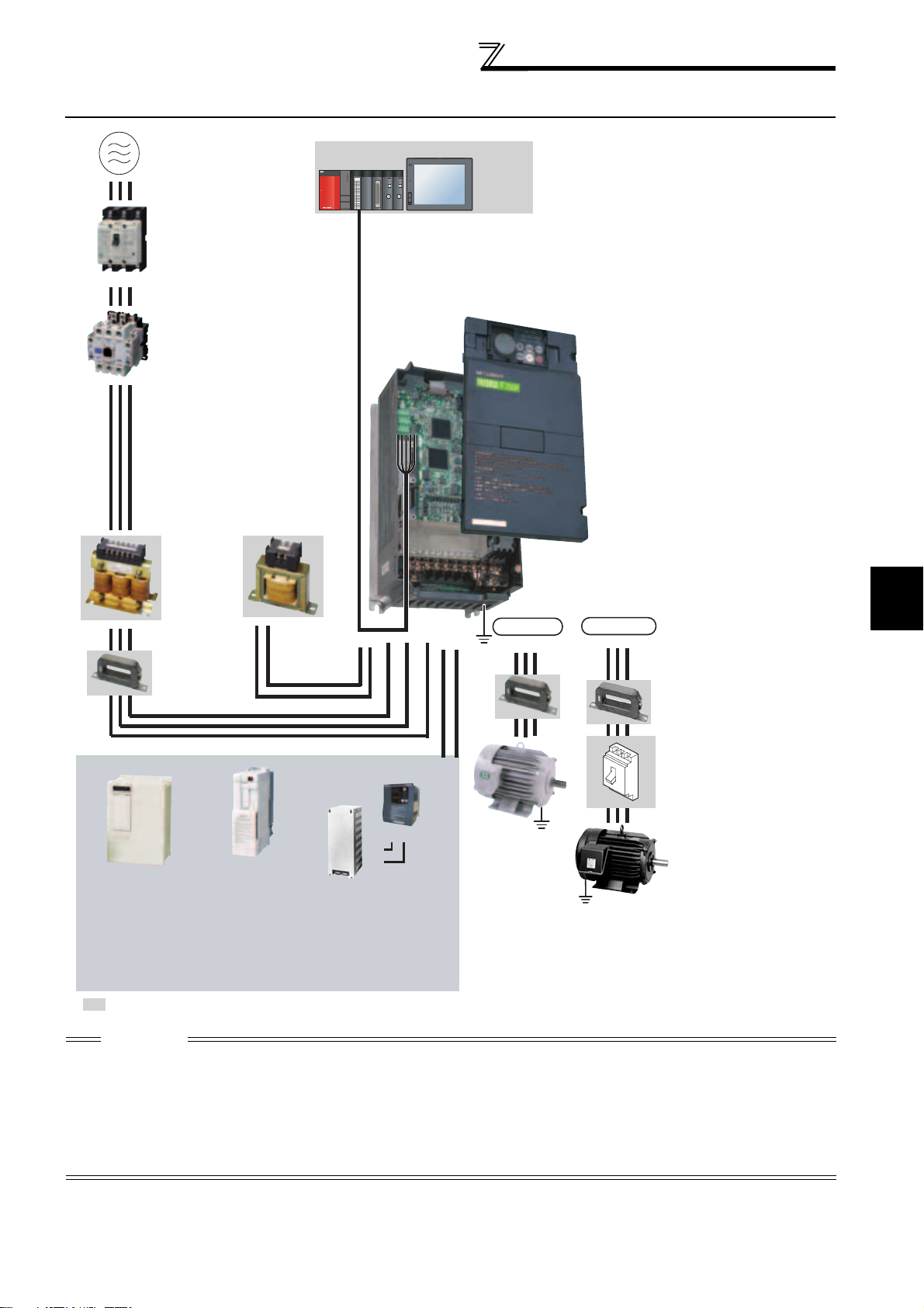
1.2 Inverter and peripheral devices
Inverter and peripheral devices
Three-phase AC power supply
Use within the permissible power supply
specifications of the inverter.
(Refer to page 346)
Moulded case circuit
breaker (MCCB)
or earth leakage circuit
breaker (ELB), fuse
The breaker must be selected carefully since
an in-rush current flows in the inverter at
power on.
(Refer to page 4)
Magnetic contactor(MC)
Install the magnetic contactor to ensure safety.
Do not use this magnetic contactor to start and stop
the inverter.
Doing so will cause the inverter life to be shortened.
(Refer to page 4)
Reactor (FR-HAL, FR-HEL)
Install reactors to suppress harmonics and to
improve the power factor. An AC reactor (FR-HAL)
(option) is required when installing the inverter near
a large power supply system (1000kVA or more).
The inverter may be damaged if you do not use
reactors.
Select the reactor according to the model.
For the 55K or lower, remove the jumpers across
terminals P/+ and P1 to connect to the DC reactor.
(Refer to page 4.)
AC reactor
(FR-HAL)
DC reactor
(FR-HEL)
EMC filter
(ferrite core)
(FR-BLF)
The 55K or lower has a built-in
common mode choke.
(Refer to page 46.)
For the 75K or higher, a
DC reactor is supplied.
Always install the reactor.
(Refer to page 42)
Power regeneration
High power factor
converter
*1
, MT-HC*2)
(FR-HC
Power supply harmonics
can be greatly suppressed.
Install this as required.
(Refer to page 38) (Refer to page 40 and 41)
*1 Compatible with the 55K or lower.
*2 Compatible with the 75K or higher.
: Install these options as required.
common converter
*1
)
(FR-CV
Power regeneration
converter (MT-RC
Greater braking capability
is obtained.
Install this as required.
*2
)
Programmable
controller
POWER
MODE
RUN
ERR
USER
BAT
BOOT
PULL
USB
PULL
Human machine interface
RUN
MNG
RUN
MNG
T.PASS
D.LINK
T.PASS
D.LINK
SD
RD
SD
RD
ERR
ERR
ERR
ERR
RS-485 terminal block
The inverter can be connected with a
computer such as a programmable
controller and with GOT (human
machine interface).
They support Mitsubishi inverter
protocol and Modbus-RTU (binary)
protocol.
R/L1 S/L2 T/L3
P/+
P1
Brake unit
*1
P/+
PR
, MT-BU5*2)
PR
P/+
(FR-BU2, FR-BU
Resistor unit
*1
, MT-BR5*2)
(FR-BR
The regeneration braking
capability of the inverter can be
exhibited fully.
Install this as required.
(Refer to page 34)
Inverter (FR-F700P)
The life of the inverter is influenced by surrounding
air temperature. The surrounding air temperature
should be as low as possible within the permissible
range. Especially when mounting the inverter
inside an enclosure, take cautions of the
surrounding air temperature. (Refer to page 10)
Wrong wiring might lead to damage of the inverter.
The control signal lines must be kept fully away
from the main circuit to protect them from noise.
(Refer to page 14)
Refer to page 15 for th e built-in EMC filter.
IPM connection
U VW
N/-P/+
Earth
IM connection
UVW
(Ground)
Generalpurpose
motor
Earth
(Ground)
Devices connected
to the output
Do not install a power
factor correction capacitor,
surge suppressor or EMC filter (capacitor) on the
output side of the inverter.
When installing a moulded case circuit breaker on
the output side of the inverter, contact each
manufacturer for selection of the moulded case
circuit breaker.
Earth (Ground)
To prevent an electric shock, always earth
(ground) the motor and inverter.
Earth
(Ground)
EMC filter
(ferrite core)
(FR-BSF01, FR-BLF)
Install an EMC filter (ferrite
core) to reduce the
electromagnetic noise
generated from the inverter.
Effective in the range from
about 0.5MHz to 5MHz.
A wire should be wound four
turns at a maximum.
(Refer to page 52.)
Contactor
Example) No-fuse
switch (DSN type)
Install a contactor in an
application where the IPM
motor is driven by the load
even at power-OFF of the
inverter. Do not open or
close the contactor while
the inverter is running
(outputting).
Dedicated IPM motor
(MM-EFS, MM-EF)
Use the specified motor.
IPM motors cannot be driven
by the commercial power
supply.
(Refer to page 359 and 360)
1
OUTLINE
CAUTION
· Do not install a power factor correction capacitor, surge suppressor or capacitor type filter on the inverter output side. This will
cause the inverter to trip or the capacitor, and surge suppressor to be damaged. If any of the above devices are connected,
immediately remove them.
· Electromagnetic wave interference
The input/output (main circuit) of the inverter includes high frequency components, which may interfere with the communication
devices (such as AM radios) used near the inverter. In this case, set the EMC filter valid to minimize interference.
(Refer to page 15.)
· Refer to the instruction manual of each option and peripheral devices for details of peripheral devices.
· An IPM motor cannot be driven by the commercial power supply.
3
Inverter and peripheral devices
1.2.1 Peripheral devices
Check the inverter model of the inverter you purchased. Appropriate peripheral devices must be selected according
to the capacity. Refer to the following list and prepare appropriate peripheral devices:
200V class
Moulded Case Circuit Breaker (MCCB) *2
Motor
Output (kW)
*1
Applicable Inverter
Model
or Earth Leakage Circuit Breaker (ELB)
(NF or NV type)
Power factor improving (AC or DC) reactor
Without With Without With
0.75 FR-F720P-0.75K 10A 10A S-N10 S-N10
1.5 FR-F720P-1.5K 15A 15A S-N10 S-N10
2.2 FR-F720P-2.2K 20A 15A S-N10 S-N10
3.7 FR-F720P-3.7K 30A 30A S-N20, S-N21 S-N10
5.5 FR-F720P-5.5K 50A 40A S-N25 S-N20, S-N21
7.5 FR-F720P-7.5K 60A 50A S-N25 S-N25
11 FR-F720P-11K 75A 75A S-N35 S-N35
15 FR-F720P-15K 125A 100A S-N50 S-N50
18.5 FR-F720P-18.5K 150A 125A S-N65 S-N50
22 FR-F720P-22K 175A 150A S-N80 S-N65
30 FR-F720P-30K 225A 175A S-N95 S-N80
37 FR-F720P-37K 250A 225A S-N150 S-N125
45 FR-F720P-45K 300A 300A S-N180 S-N150
55 FR-F720P-55K 400A 350A S-N220 S-N180
75 FR-F720P-75K ⎯ 400A ⎯
90 FR-F720P-90K ⎯ 400A ⎯
110 F R- F 7 2 0 P-110K ⎯ 500A ⎯
*1 Selections for use of the Mitsubishi 4-pole standard motor with power supply voltage of 200VAC 50Hz.
*2 Select the MCCB according to the power supply capacity.
Install one MCCB per inverter.
For using commercial-power supply operation, select a breaker with capacity which allows the motor to be
directly power supplied.
For installation in the United States, Class RK5, Class J, Class CC, Class L, Class T or any faster acting
fuses or UL 489 Molded Case Circuit Breaker (MCCB) must be provided, in accordance with the National
Electrical Code and any applicable local codes.
For installation in Canada, Class RK5, Class J, Class CC, Class L, Class T or any faster acting fuses or UL
489 Molded Case Circuit Breaker (MCCB) must be provided, in accordance with the Canada Electrical
Code and any applicable provincial codes. (Refer to the Instruction Manual (basic).)
*3 Magnetic contactor is selected based on the AC-1 class. The electrical durability of magnetic contactor is 500,000 times. When the magnetic
contactor is used for emergency stop during motor driving, the electrical durability is 25 times.
When using the MC for emergency stop during motor driving or using on the motor side during commercial-power supply operation, select the
MC with class AC-3 rated current for the motor rated current.
Input Side Magnetic Contactor*3
S-N300
S-N300
S-N400
MCCB INV
MCCB INV
M
M
CAUTION
⋅ When the inverter capacity is larger than the motor capacity, select an MCCB and a magnetic contactor according to the
inverter model, and select cable and reactor according to the motor output.
⋅ When the breaker on the inverter primary side trips, check for the wiring fault (short circuit), damage to internal parts of the
inverter, etc. Identify the cause of the trip, then remove the cause and power ON the breaker.
4
Inverter and peripheral devices
400V class
Motor
Output
(kW)
*1
0.75 FR-F740P-0.75K 5A 5A S-N10 S-N10
1.5 FR-F740P-1.5K 10A 10A S-N10 S-N10
2.2 FR-F740P-2.2K 10A 10A S-N10 S-N10
3.7 FR-F740P-3.7K 20A 15A S-N10 S-N10
5.5 FR-F740P-5.5K 30A 20A S-N20, S-N21 S-N11, S-N12
7.5 FR-F740P-7.5K 30A 30A S-N20, S-N21 S-N20, S-N21
11 FR-F740P-11K 50A 40A S-N20, S-N21 S-N20, S-N21
15 FR-F740P-15K 60A 50A S-N25 S-N20, S-N21
18.5 FR-F740P-18.5K 75A 60A S-N25 S-N25
22 FR-F740P-22K 100A 75A S-N35 S-N25
30 FR-F740P-30K 125A 100A S-N50 S-N50
37 FR-F740P-37K 150A 125A S-N65 S-N50
45 FR-F740P-45K 175A 150A S-N80 S-N65
55 FR-F740P-55K 200A 175A S-N80 S-N80
75 FR-F740P-75K ⎯ 225A ⎯ S-N95
90 FR-F740P-90K ⎯ 225A ⎯ S-N150
110 F R -F740P- 110K ⎯ 225A ⎯ S-N180
132 FR-F740P-132K ⎯ 400A ⎯ S-N220
150 FR-F740P-160K ⎯ 400A ⎯ S-N300
160 FR-F740P-160K ⎯ 400A ⎯ S-N300
185 FR-F740P-185K ⎯ 400A ⎯ S-N300
220 FR-F740P-220K ⎯ 500A ⎯ S-N400
250 FR-F740P-250K ⎯ 600A ⎯ S-N600
280 FR-F740P-280K ⎯ 600A ⎯ S-N600
315 FR-F740P-315K ⎯ 700A ⎯ S-N600
355 FR-F740P-355K ⎯ 800A ⎯ S-N600
400 FR-F740P-400K ⎯ 900A ⎯ S-N800
450 FR-F740P-450K ⎯ 1000A ⎯
500 FR-F740P-500K ⎯ 1200A ⎯
560 FR-F740P-560K ⎯ 1500A ⎯
*1 Selections for use of the Mitsubishi 4-pole standard motor with power supply voltage of 400VAC 50Hz.
*2 Select the MCCB according to the power supply capacity.
Install one MCCB per inverter.
For using commercial-power supply operation, select a breaker with capacity which allows the motor to be
directly power supplied.
For installation in the United States, Class RK5, Class J, Class CC, Class L, Class T or any faster acting
fuses or UL 489 Molded Case Circuit Breaker (MCCB) must be provided, in accordance with the National
Electrical Code and any applicable local codes.
For installation in Canada, Class RK5, Class J, Class CC, Class L, Class T or any faster acting fuses or UL
489 Molded Case Circuit Breaker (MCCB) must be provided, in accordance with the Canada Electrical
Code and any applicable provincial codes. (Refer to the Instruction Manual (basic).)
*3 Magnetic contactor is selected based on the AC-1 class. The electrical durability of magnetic contactor is 500,000 times. When the magnetic
contactor is used for emergency stop during motor driving, the electrical durability is 25 times.
When using the MC for emergency stop during motor driving or using on the motor side during commercial-power supply operation, select the
MC with class AC-3 rated current for the motor rated current.
Applicable Inverter
Model
CAUTION
⋅ When the inverter capacity is larger than the motor capacity, select an MCCB and a magnetic contactor according to the
inverter model, and select cable and reactor according to the motor output.
⋅ When the breaker on the inverter primary side trips, check for the wiring fault (short circuit), damage to internal parts of the
inverter, etc. Identify the cause of the trip, then remove the cause and power ON the breaker.
Moulded Case Circuit Breaker (MCCB) *2
or Earth Leakage Circuit Breaker (ELB)
Input Side Magnetic Contactor*3
(NF or NV type)
Power factor improving (AC or DC) reactor
Without With Without With
1000A
Rated product
1000A
Rated product
1200A
Rated product
MCCB INV
MCCB INV
M
M
1
OUTLINE
5
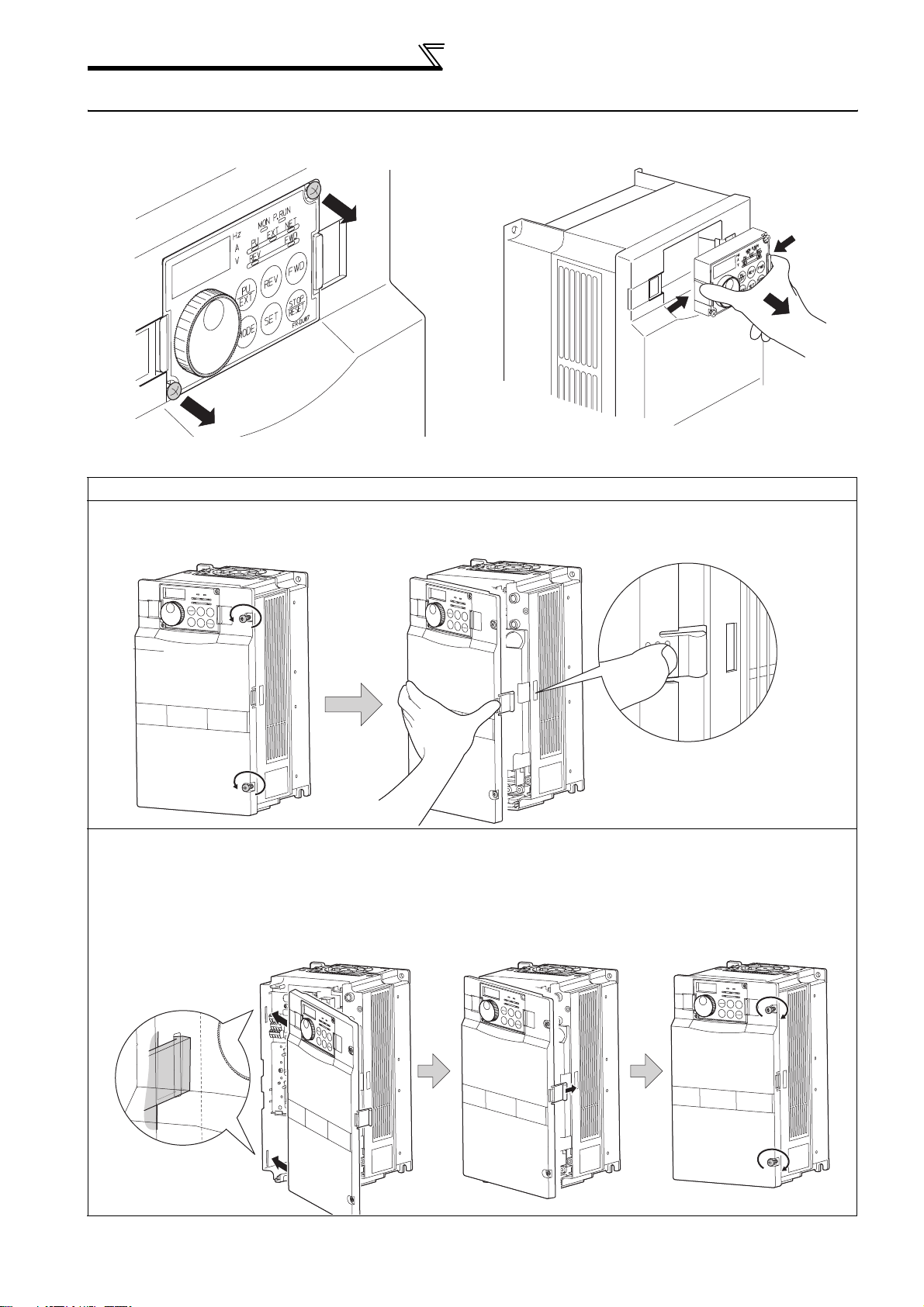
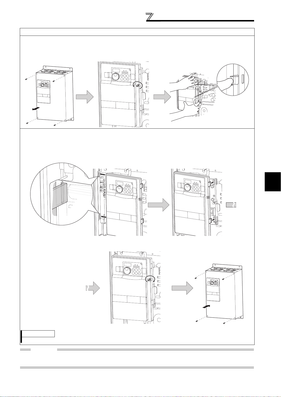
Method of removal and reinstallation of the
front cover
1.3 Method of removal and reinstallation of the front cover
•Removal of the operation panel
1) Loosen the two screws on the operation panel.
(These screws cannot be removed.)
When reinstalling the operation panel, insert it straight to reinstall securely and tighten the fixed screws of the
operation panel.
2) Push the left and right hooks of the operation panel
and pull the operation panel toward you to remove.
FR-F720P-30K or lower, FR-F740P-30K or lower
Removal
•
1) Loosen the installation screws of the
front cover.
Front cover
2) Pull the front cover toward you to remove by pushing an
installation hook using left fixed hooks as supports.
Front cover
•Reinstallation
1) Insert the two fixed hooks on the left side of
the front cover into the sockets of the
inverter.
2) Using the fixed hooks as supports,
securely press the front cover
against the inverter.
(Although installation can be done
with the operation panel mounted,
make sure that a connector is
securely fixed.)
Installation hook
3) Tighten the installation
screws and fix the front
cover.
Front cover
Front cover
Front cover
6
FR-F720P-37K or higher, FR-F740P-37K or higher
•
Removal
1) Remove installation screws on
the front cover 1 to remove the
2) Loosen the installation
screws of the front cover 2.
front cover 1.
Front cover 1
Front cover 2
•Reinstallation
1) Insert the two fixed hooks on the left side of the
front cover 2 into the sockets of the inverter.
Method of removal and reinstallation of the
front cover
3) Pull the front cover 2 toward you to
remove by pushing an installation
hook on the right side using left
fixed hooks as supports.
Installation hook
2) Using the fixed hooks as supports, securely
press the front cover 2 against the inverter.
(Although installation can be done with the
operation panel mounted, make sure that a
connector is securely fixed.)
Front cover 2 Front cover 2
3) Fix the front cover 2 with the
installation screws.
Front cover 2
1
OUTLINE
4) Fix the front cover 1 with the
installation screws.
Front cover 1
REMARKS
⋅ For the FR-F740P-185K or higher, the front cover 1 is separated into two parts.
CAUTION
Fully make sure that the front cover has been reinstalled securely. Always tighten the installation screws of the front cover.
The same serial number is printed on the capacity plate of the front cover and the rating plate of the inverter. Before reinstalling the
front cover, check the serial numbers to ensure that the cover removed is reinstalled to the inverter from where it was removed.
7

Installation of the inverter and
enclosure design
1.4 Installation of the inverter and enclosure design
When an inverter enclosure is to be designed and manufactured, heat generated by contained equipment, etc., the
environment of an operating place, and others must be fully considered to determine the enclosure structure, size and
equipment layout. The inverter unit uses many semiconductor devices. To ensure higher reliability and long period of
operation, operate the inverter in the ambient environment that completely satisfies the equipment specifications.
1.4.1 Inverter installation environment
As the inverter installation environment should satisfy the standard specifications indicated in the following table,
operation in any place that does not meet these conditions not only deteriorates the performance and life of the
inverter, but also causes a failure. Refer to the following points and take adequate measures.
Environmental standard specifications of inverter
Item Description
Surrounding air temperature -10 to +50°C (non-freezing)
Ambient humidity 90% RH maximum (non-condensing)
Atmosphere Free from corrosive and explosive gases, dust and dirt
Maximum Altitude 1,000m or less
Vibration
*1 2.9m/s2 or less for the 185K or higher.
2
or less *1 at 10 to 55Hz (directions of X, Y, Z axes)
5.9m/s
(1) Temperature
The permissible surrounding air temperature of the inverter is between -10°C and +50°C. Always operate the inverter
within this temperature range. Operation outside this range will considerably shorten the service lives of the
semiconductors, parts, capacitors and others. Take the following measures so that the surrounding air temperature of
the inverter falls within the specified range.
1)Measures against high temperature
• Use a forced ventilation system or similar cooling system. (Refer to page 10.)
• Install the enclosure in an air-conditioned electrical chamber.
• Block direct sunlight.
• Provide a shield or similar plate to avoid direct exposure to the radiated heat and wind of a heat source.
• Ventilate the area around the enclosure well.
2)Measures against low temperature
• Provide a space heater in the enclosure.
• Do not power OFF the inverter. (Keep the start signal of the inverter OFF.)
3)Sudden temperature changes
• Select an installation place where temperature does not change suddenly.
• Avoid installing the inverter near the air outlet of an air conditioner.
• If temperature changes are caused by opening/closing of a door, install the inverter away from the door.
(2) Humidity
Normally operate the inverter within the 45 to 90% range of the ambient humidity. Too high humidity will pose problems
of reduced insulation and metal corrosion. On the other hand, too low humidity may produce a spatial electrical
breakdown. The insulation distance specified in JEM1103 "Control Equipment Insulator" is defined as humidity 45 to
85%.
1)Measures against high humidity
• Make the enclosure enclosed, and provide it with a hygroscopic agent.
• Take dry air into the enclosure from outside.
• Provide a space heater in the enclosure.
2)Measures against low humidity
What is important in fitting or inspection of the unit in this status is to discharge your body (static electricity)
beforehand and keep your body from contact with the parts and patterns, besides blowing air of proper humidity into
the enclosure from outside.
3)Measures against condensation
Condensation may occur if frequent operation stops change the in-enclosure temperature suddenly or if the outsideair temperature changes suddenly.
Condensation causes such faults as reduced insulation and corrosion.
• Take the measures against high humidity in 1).
• Do not power off the inverter. (Keep the start signal of the inverter OFF.)
8

Installation of the inverter and
enclosure design
(3) Dust, dirt, oil mist
Dust and dirt will cause such faults as poor contact of contact points, reduced insulation or reduced cooling effect due
to moisture absorption of accumulated dust and dirt, and in-enclosure temperature rise due to clogged filter.
In the atmosphere where conductive powder floats, dust and dirt will cause such faults as malfunction, deteriorated
insulation and short circuit in a short time.
Since oil mist will cause similar conditions, it is necessary to take adequate measures.
Countermeasures
• Place in a totally enclosed enclosure.
Take measures if the in-enclosure temperature rises. (Refer to page 10.)
• Purge air.
Pump clean air from outside to make the in-enclosure pressure higher than the outside-air pressure.
(4) Corrosive gas, salt damage
If the inverter is exposed to corrosive gas or to salt near a beach, the printed board patterns and parts will corrode or
the relays and switches will result in poor contact.
In such places, take the measures given in Section (3).
(5) Explosive, flammable gases
As the inverter is non-explosion proof, it must be contained in an explosion proof enclosure.
In places where explosion may be caused by explosive gas, dust or dirt, an enclosure cannot be used unless it
structurally complies with the guidelines and has passed the specified tests. This makes the enclosure itself expensive
(including the test charges).
The best way is to avoid installation in such places and install the inverter in a non-hazardous place.
(6) Highland
Use the inverter at the altitude of within 1000m.
If it is used at a higher place, it is likely that thin air will reduce the cooling effect and low air pressure will deteriorate
dielectric strength.
(7) Vibration, impact
The vibration resistance of the inverter is up to 5.9m/s2 (2.9m/s2 for the 185K or higher) at 10 to 55Hz frequency
(directions of X, Y, Z axes) and 1mm amplitude.
Vibration or impact, if less than the specified value, applied for a long time may make the mechanism loose or cause
poor contact to the connectors.
Especially when impact is imposed repeatedly, caution must be taken as the part pins are likely to break.
Countermeasures
• Provide the enclosure with rubber vibration isolators.
• Strengthen the structure to prevent the enclosure from resonance.
• Install the enclosure away from sources of vibration.
1
OUTLINE
9
Installation of the inverter and
enclosure design
1.4.2 Cooling system for inverter enclosure
From the enclosure that contains the inverter, the heat of the inverter and other equipment (transformers, lamps,
resistors, etc.) and the incoming heat such as direct sunlight must be dissipated to keep the in-enclosure temperature
lower than the permissible temperatures of the in-enclosure equipment including the inverter.
The cooling systems are classified as follows in terms of the cooling calculation method.
1) Cooling by natural heat dissipation from the enclosure surface (Totally enclosed type)
2) Cooling by heat sink (Aluminum fin, etc.)
3) Cooling by ventilation (Forced ventilation type, pipe ventilation type)
4) Cooling by heat exchanger or cooler (Heat pipe, cooler, etc.)
Cooling System Enclosure Structure Comment
Natural
cooling
Forced
cooling
Natural ventilation
(Enclosed, open type)
Natural ventilation
(Totally enclosed type)
Heatsink cooling
Forced ventilation
Heat pipe Totally enclosed type for enclosure downsizing.
heatsink
INV
INV
INV
INV
Heat
pipe
INV
Low in cost and generally used, but the enclosure size
increases as the inverter capacity increases. For
relatively small capacities.
Being a totally enclosed type, the most appropriate for
hostile environment having dust, dirt, oil mist, etc. The
enclosure size increases depending on the inverter
capacity.
Having restrictions on the heatsink mounting position
and area, and designed for relative small capacities.
For general indoor installation. Appropriate for
enclosure downsizing and cost reduction, and often
used.
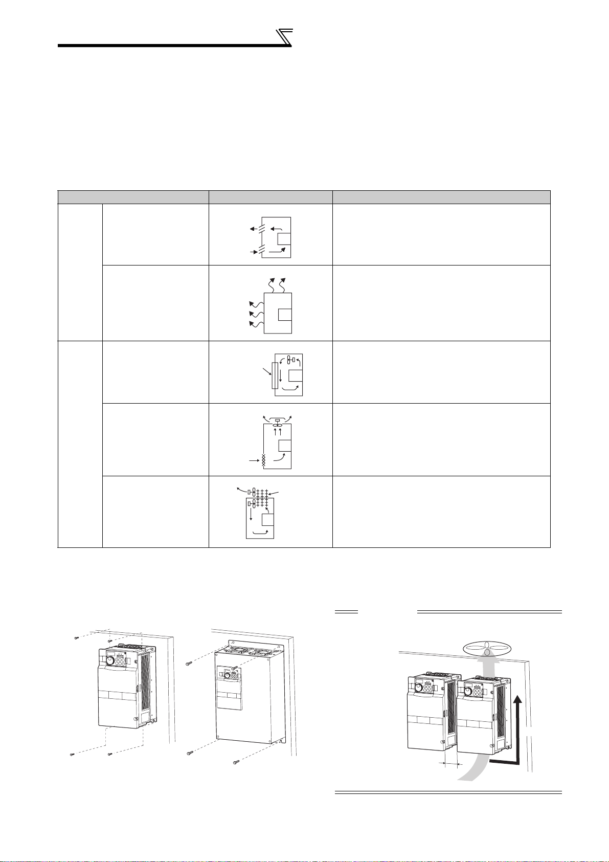
1.4.3 Inverter placement
(1) Installation of the inverter
Installation on the enclosure
30K or lower 37K or higher
Fix six positions for the FR-F740P185K to 400K and fix eight positions
for the FR-F740P-450K to 560K.
10
CAUTION
When encasing multiple inverters, install them in parallel as
a cooling measure. Install the inverter vertically.
Vertical
*
*Refer to the clearances on the next page.
Installation of the inverter and
enclosure design
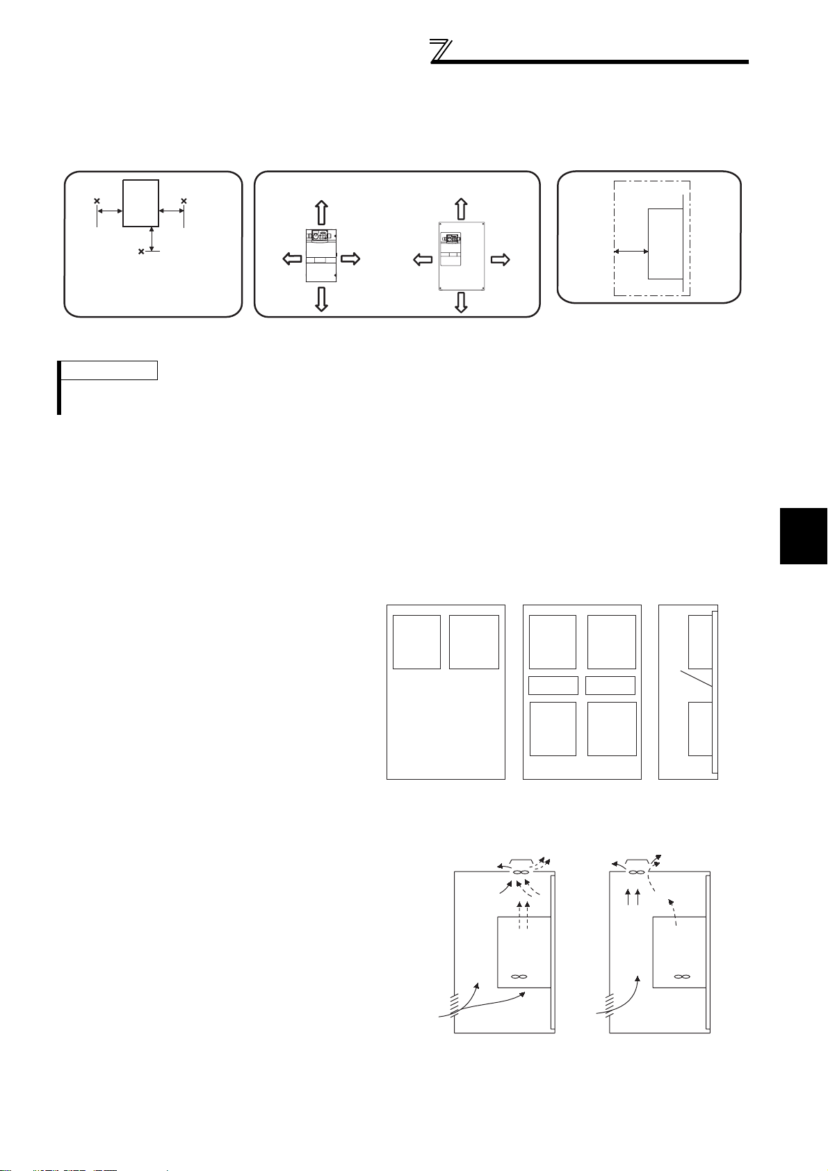
(2) Clearances around the inverter
To ensure ease of heat dissipation and maintenance, leave at least the shown clearances around the inverter. At least the
following clearances are required under the inverter as a wiring space, and above the inverter as a heat dissipation space.
Surrounding air temperature and humidity
Measurement
position
Inverter
5cm
Measurement
position
5cm
5cm
Temperature: -10°C to 50°C
Humidity: 90% RH maximum
Leave enough clearances as a
cooling measure.
Clearances
55K or lower 75K or higher
10cm or more
5cm
or more *
5cm
or more *
10cm or more
*1cm or more for 3.7K or lower
10cm
or more
(front)
20cm or more
10cm
or more
20cm or more
Clearances (side)
Inverter
5cm
or more
*
1cm or more for 3.7K or lower
REMARKS
• For replacing the cooling fan of the FR-F740P-185K or higher, 30cm of space is necessary in front of the inverter.
Refer to page 336 for fan replacement.
(3) Inverter mounting orientation
Mount the inverter on a wall as specified. Do not mount it horizontally or any other way.
(4) Above the inverter
Heat is blown up from inside the inverter by the small fan built in the unit. Any equipment placed above the inverter
should be heat resistant.
1
(5) Arrangement of multiple inverters
When multiple inverters are placed in the same
enclosure, generally arrange them horizontally as
shown in the right figure (a). When it is inevitable to
arrange them vertically to minimize space, take such
Inverter
measures as to provide guides since heat from the
bottom inverters can increase the temperatures in
the top inverters, causing inverter failures.
When mounting multiple inverters, fully take caution
not to make the surrounding air temperature of the
inverter higher than the permissible value by
providing ventilation and increasing the enclosure
(a) Horizontal arrangement
size.
(6) Placement of ventilation fan and inverter
Heat generated in the inverter is blown up from the bottom of
the unit as warm air by the cooling fan. When installing a
ventilation fan for that heat, determine the place of ventilation
fan installation after fully considering an air flow. (Air passes
through areas of low resistance. Make an airway and airflow
plates to expose the inverter to cool air.)
Inverter
Enclosure Enclosure
Inverter
Guide Guide
Inverter
Inverter
Inverter
(b) Vertical arrangement
Arrangement of multiple inverters
Inverter Inverter
OUTLINE
Guide
<Good example> <Bad example>
Placement of ventilation fan and inverter
11

MEMO
12

2 WIRING
This chapter explains the basic "WIRING" for use of this product.
Always read the instructions before using the equipment.
2.1 Wiring ...................................................................... 14
2.2 Main circuit terminal specifications..........................16
2.3 Control circuit specifications....................................26
2.4 Connection of stand-alone option units...................34
1
2
3
4
5
6
13
7
Wiring
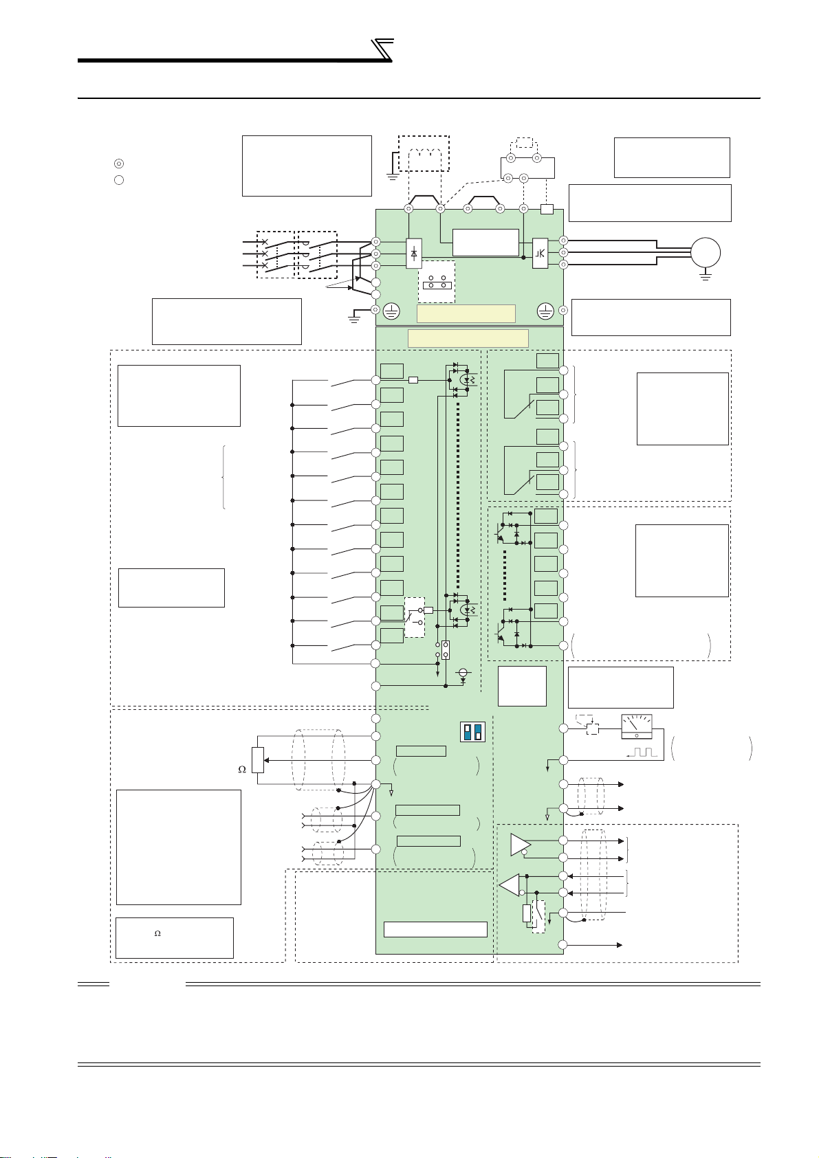
2.1 Wiring
2.1.1 Terminal connection diagram
Middle speed
Jog operation
Output stop
power failure
1/2W1k
*5
*1. DC reactor (FR-HEL)
Be sure to connect the DC reactor
supplied with the 75K or higher.
When a DC reactor is connected
to the 55K or lower, remove the
jumper across P1 and P/+.
Jumper
MC
*2
MCCB
Earth
(Ground)
Forward
rotation
start
Reverse
rotation
start
High speed
Low speed
Reset
24VDC power supply
3
2
1
Auxiliary
(+)
(-)
input
Terminal
4 input
(Current
input)
(+)
(-)
Connector
for plug-in option
connection
Sink logic
Main circuit terminal
Control circuit terminal
Three-phase AC
power supply
*2. To supply power to the
control circuit separately,
remove the jumper across
R1/L11 and S1/L21.
Control input signals (No voltage input allowed)
Terminal functions vary
with the input terminal
assignment
(Pr. 178 to Pr. 189)
(Refer to page 133)
Start self-holding selection
Multi-speed
selection
Second function selection
*3. AU terminal can be
used as PTC input
terminal.
Terminal 4 input selection
(Current input selection)
Selection of automatic restart
after instantaneous
Contact input common
(Common for external power supply transistor)
Frequency setting signal (Analog)
Frequency setting
potentiometer
*
4. Terminal input specifications
can be changed by analog
input specifications switchover
(Pr. 73, Pr. 267). Set the
voltage/current input switch in
the OFF position to select
voltage input (0 to 5V/0 to
10V) and ON to select current
input (0 to 20mA).
(Refer to page 185)
*
5. It is recommended to use
2W1k when the
frequency setting signal is
changed frequently.
*1
Earth
Jumper
(ground)
P1
P/+
R/L1
S/L2
T/L3
ON
R1/L11
S1/L21
OFF
Main circuit
Control circuit
STF
STR
STOP
RH
RM
RL
JOG
RT
MRS
RES
*3
AU
AU
PTC
CS
SD
PC
10E(+10V)
10(+5V)
2
5
1
4
SOURCE
*4
Voltage/current
input switch
ON
OFF
0 to 5VDC
0 to 10VDC
0 to 20mADC
selectable
(Analog common)
0 to ±10VDC
0 to ±5VDC
selectable
4 to 20mADC
0 to 5VDC
0 to 10VDC
selectable
Option connector 1
Jumper
PR*7
Inrush current
limit circuit
EMC filter
ON/OFF
connector
SINK
24V
2
4
Initial value
*
4
Initial
value
*
4
Initial
value
*
4
PX*7
N/-
*8
PU
connector
TXD+
RXD+
RXD-
Terminating
resistor
VCC
Resistor unit
(Option)
*6. A CN8 (for MT-BU5)
Brake unit
(Option)
*7.
Do not use PR and PX terminals.
Please do not remove the jumper
CN8
connected to terminal PR and PX.
*6
U
V
W
*8.
The 200V class 0.75K and 1.5K
are not provided with the ON/OFF
connector EMC filter.
C1
B1
Relay output 1
(Fault output)
A1
C2
B2
Relay output 2
A2
RUN
Running
SU
Up to frequency
IPF
Instantaneous
power failure
OL
Overload
FU
Frequency detection
SE
Open collector output common
Sink
/
source common
*
9. It is not necessary
when calibrating the
indicator from the
operation panel.
+-
FM
Calibration
resistor *9
SD
AM
5
TXD-
SG
connector is provided
with the 75K or higher.
Motor
M
Relay output
Terminal functions
vary with the output
terminal assignment
(Pr. 195, Pr. 196)
(Refer to page 140)
Open collector output
Terminal functions
vary with the output
terminal assignment
(Pr. 190 to Pr. 194)
(Refer to page 140)
Indicator
(Frequency meter, etc.)
Moving-coil type
1mA full-scale
(+)
Analog signal output
(0 to 10VDC)
(-)
RS-485 terminals
Data transmission
Data reception
GND
(Permissible load
5V
current 100mA)
Earth
(ground)
cable
CAUTION
· To prevent a malfunction due to noise, keep the signal cables more than 10cm away from the power cables. Also separate the
main circuit wire of the input side and the output side.
· After wiring, wire offcuts must not be left in the inverter.
Wire offcuts can cause an alarm, failure or malfunction. Always keep the inverter clean.
When drilling mounting holes in an enclosure etc. take care not to allow chips and other foreign matter to enter the inverter.
· Set the voltage/current input switch correctly. Operation with a wrong setting may cause a fault, failure or malfunction.
14
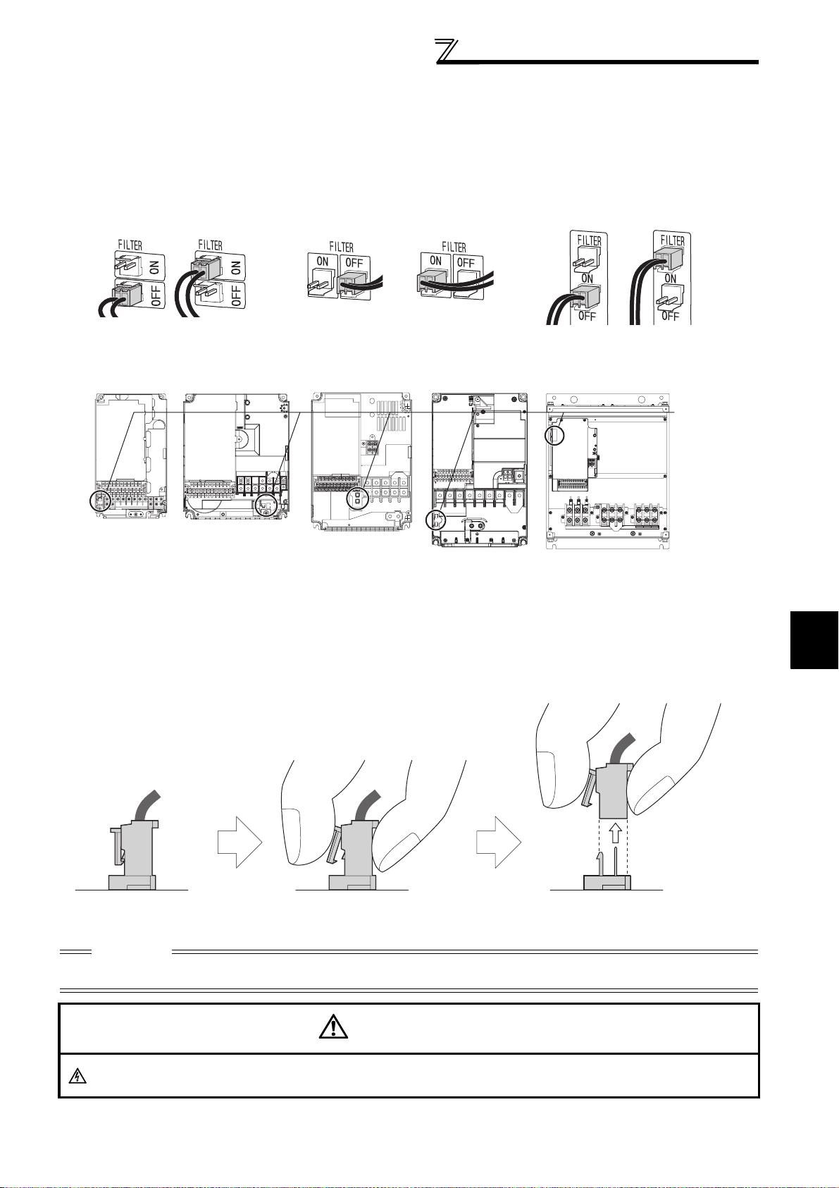
Wiring
r
r
2.1.2 EMC filter
This inverter is equipped with a built-in EMC filter (capacitive filter) and common mode choke.
The EMC filter is effective for reduction of air-propagated noise on the input side of the inverter.
The EMC filter is factory-set to disable (OFF). To enable it, fit the EMC filter ON/OFF connector to the ON position.
The input side common mode choke, built-in the 55K or lower inverter, is always valid regardless of ON/OFF of the
EMC filter ON/OFF connector.
5.5K or lower
EMC filter OFF EMC filter OFF EMC filter OFFEMC filter ON EMC filter ON EMC filter ON
(initial setting) (initial setting) (initial setting)
FR-F720P-2.2K to 5.5K
FR-F740P-0.75K to 5.5K
FR-F720P-7.5K, 11K
FR-F740P-7.5K, 11K
FR-F740P-15K, 18.5K
7.5K, 11K
FR-F720P-15K
FR-F720P-18.5K to 30K
FR-F740P-22K, 30K
15K or higher
FR-F720P-37K or higher
FR-F740P-37K or higher
EMC filte
ON/OFF
connecto
VUW
The FR-F720P-0.75K and 1.5K are not provided with the EMC filter ON/OFF connector. (Always ON)
<How to disconnect the connector>
(1) Before removing a front cover, check to make sure that the indication of the inverter operation panel is OFF, wait
for at least 10 minutes after the power supply has been switched OFF, and check that there are no residual voltage
using a tester or the like. (For the front cover removal method, refer to page 6.)
(2) When disconnecting the connector, push the fixing tab and pull the connector straight without pulling the cable or
forcibly pulling the connector with the tab fixed. When installing the connector, also engage the fixing tab securely.
If it is difficult to disconnect the connector, use a pair of long-nose pliers, etc.
2
EMC filter
ON/OFF connector
(Side view)
Disengage connector fixing tab. With tab disengaged,
pull up connector straight.
CAUTION
⋅ Fit the connector to either ON or OFF.
⋅ Enabling (turning ON) the EMC filter increases leakage current. (Refer to page 45)
WARNING
While power is ON or when the inverter is running, do not open the front cover. Otherwise you may get an electric shock.
WIRING
15
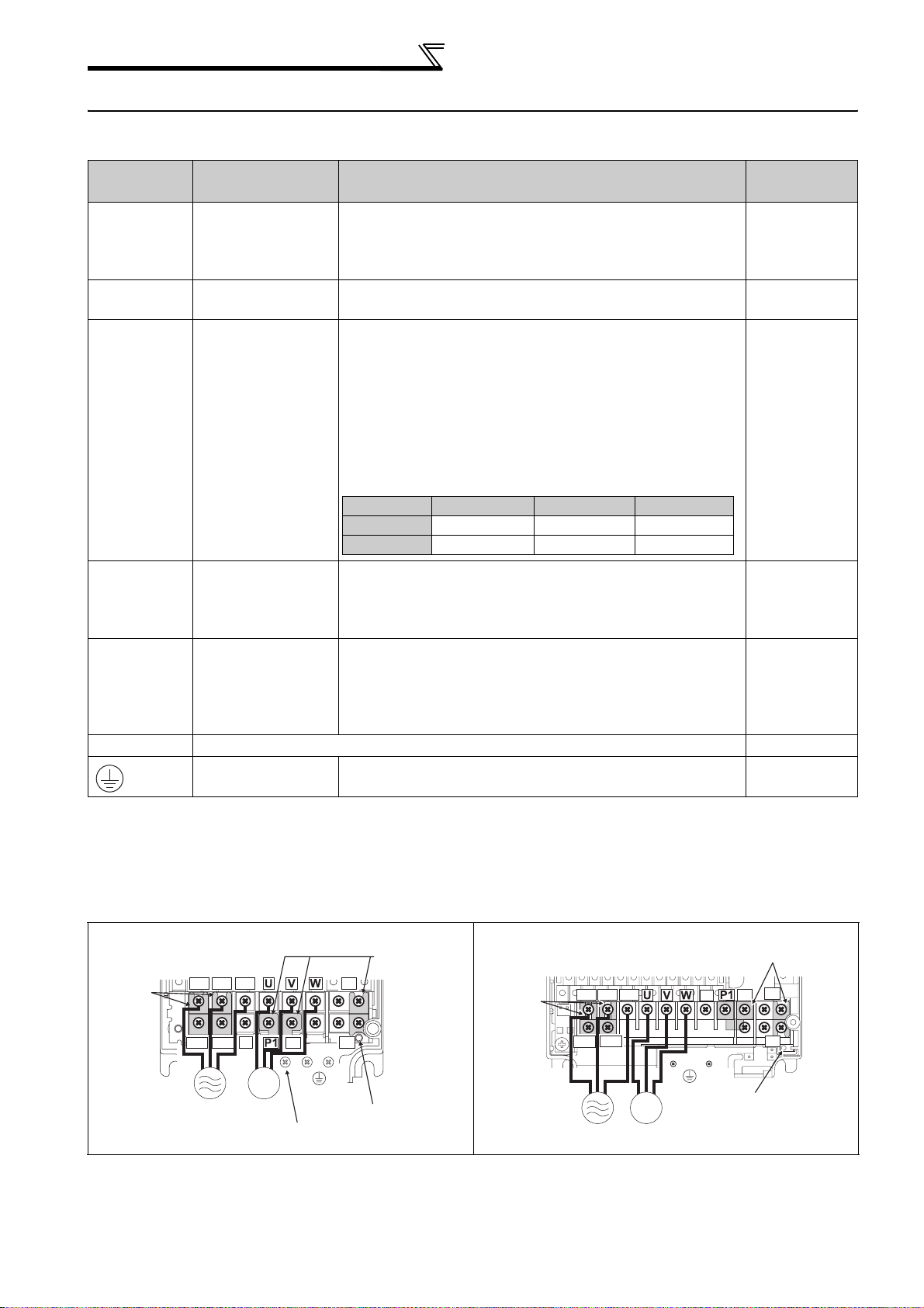
Main circuit terminal specifications
2.2 Main circuit terminal specifications
2.2.1 Specification of main circuit terminal
Terminal
Symbol
R/L1,
S/L2,
T/L3
U, V, W Inverter output
Terminal N ame Description
Connect to the commercial power supply.
AC power input
Keep these terminals open when using the high power
factor converter (FR-HC, MT-HC) or power regeneration
common converter (FR-CV).
Connect a three-phase squirrel-cage motor or dedicated
IPM motor.
Connected to the AC power supply terminals R/L1 and S/
L2. To retain the fault display and fault output or when
using the high power factor converter (FR-HC, MT-HC) or
power regeneration common converter (FR-CV), remove
the jumpers from terminals R/L1 and R1/L11, and S/L2
R1/L11,
S1/L21
Power supply for
control circuit
and S1/L21, and apply external power to these terminals.
The power capacity necessary when separate power is
supplied from R1/L11 and S1/L21 differs according to the
inverter capacity.
15K or lower 18.5K 22K or higher
200V class 60VA 80VA 80VA
400V class 60VA 60VA 80VA
Connect the brake unit (FR-BU2, FR-BU, BU and MT-
P/+, N/-
Brake unit
connection
BU5), power regeneration common converter (FR-CV),
high power factor converter (FR-HC and MT-HC) or power
regeneration converter (MT-RC).
For the 55K or lower, remove the jumper across terminals
P/+ and P1, and connect the DC reactor. (Be sure to
connect the DC reactor supplied with the 75K or higher.)
When a DC reactor is not connected, the jumper across
P/+, P1
DC reactor
connection
terminals P/+ and P1 should not be removed.
PR, PX Please do not remove or use terminals PR and PX or the jumper connected.
Earth (ground)
For earthing (grounding) the inverter chassis. Must be
earthed (grounded).
Refer to
Page
16
16
24
34
42
—
22
2.2.2 Terminal arrangement of the main circuit terminal, power supply and the motor wiring
200V class
FR-F720P-0.75K, 1.5K FR-F720P-2.2K to 5.5K
Jumper
PR
P/+
PX
Charge lamp
16
Jumper
Screw size (M4)
R/L1
S/L2
R1/L11
S1/L21
Power supply
Jumper
T/L3
N/-
P/+
M
Motor
As this is an inside cover fixing screw,
do not remove it.
PX
Screw size
(M4)
PR
Charge lamp
Jumper
Screw size (M4)
R/L1 S/L2 T/L3
R1/L11 S1/L21
Power
supply
M
Motor
N/-
Screw size
(M4)
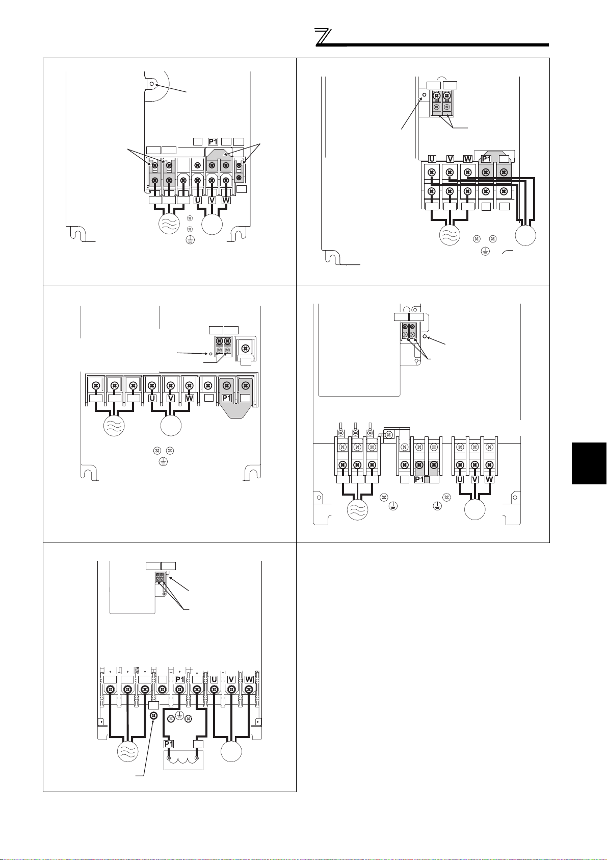
FR-F720P-7.5K, 11K FR-F720P-15K
r
Main circuit terminal specifications
Charge lamp
Jumper
Screw size
(M5)
**
R1/L11 S1/L21
R/L1 S/L2 T/L3
N/-
P/+
PR
*
PX
Jumpe
*
Charge lamp
Screw size (M5)
M
Power supply
* Screw size of terminal
R1/L11, S1/L21, PR
and PX is M4.
Screw size (M5)
FR-F720P-18.5K to 30K FR-F720P-37K to 55K
Screw size
(M6 for 18.5K,
M8 for 22K and 30K)
Screw size (M4)
Charge lamp
Jumper
Motor
R1/L11 S1/L21
Screw size
(M4)
PR
R/L1 S/L2 T/L3
R1/L11 S1/L21
R1/L11 S1/L21
Screw size
Power supply
Screw size (M5)
Charge lamp
Jumper
(M4)
Jumper
Jumper
N/-
P/+
PR
M
Motor
R/L1 S/L2 T/L3
Power supply
FR-F720P-75K to 110K
R/L1 S/L2 T/L3
M
Motor
Screw size (M6)
R1/L11 S1/L21
Screw size (M4)
N/-
N/-
Jumper
Charge lamp
Jumper
Screw size (M12)
P/+
P/+
R/L1 S/L2 T/L3
Power
supply
Screw size
(M8 for 37K, M10 for 45K and 55K)
N/-
P/+
Jumper
Screw size
(M6 for 37K,
M8 for 45K and 55K)
2
M
Motor
WIRING
Power supply
Screw size (M12)
(for option)
P/+
Screw size
(M10)
P/+
DC reactor
M
Motor
17
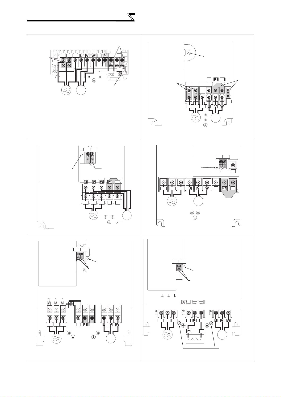
Main circuit terminal specifications
r
400V class
FR-F740P-0.75K to 5.5K FR-F740P-7.5K, 11K
Jumper
Screw size (M4)
R/L1 S/L2 T/L3
N/-
P/+
Jumper
PR
Charge lamp
R1/L11 S1/L21
Power
supply
M
Motor
Screw size
(M4)
PX
Jumper
Charge lamp
Screw size
FR-F740P-15K, 18.5K FR-F740P-22K, 30K
R1/L11 S1/L21
Screw size
(M4)
Charge lamp
Screw size (M5)
R/L1 S/L2 T/L3
Jumper
Jumper
N/-
Screw size (M6)
P/+
R/L1 S/L2 T/L3
PR
Power supply
M
Power supply
Screw size (M5)
Motor
R1/L11 S1/L21
(M4)
R/L1 S/L2 T/L3
Power supply
Charge lamp
Screw size (M6)
N/-
M
Motor
Screw size
(M4)
Screw size (M4)
Jumper
M
Motor
P/+
PR
R1/L11 S1/L21
N/-
Jumper
Jumpe
PX
PR
P/+
FR-F740P-37K to 55K FR-F740P-75K to 110K
R1/L11 S1/L21
Screw size(M4)
Power
supply
R1/L11 S1/L21
R/L1 S/L2 T/L3
Power
supply
Jumper
Screw size (M6 for 37K,
M8 for 45K and 55K)
N/-
P/+
Jumper
Screw size
(M6 for 37K,
M8 for 45K and 55K)
Charge lamp
M
Motor
Screw size (M4)
Screw size
(M8 for 75K,
M10 for 90K and 110K)
R/L1 S/L2 T/L3
Charge lamp
Jumper
Screw size (M10)
N/-
P/+
P/+
DC reactor
Screw size
(M8 for 75K,
M10 for 90K and 110K)
M
Motor
Screw size
(M8 for 75K,
M10 for 90K and 110K)
18
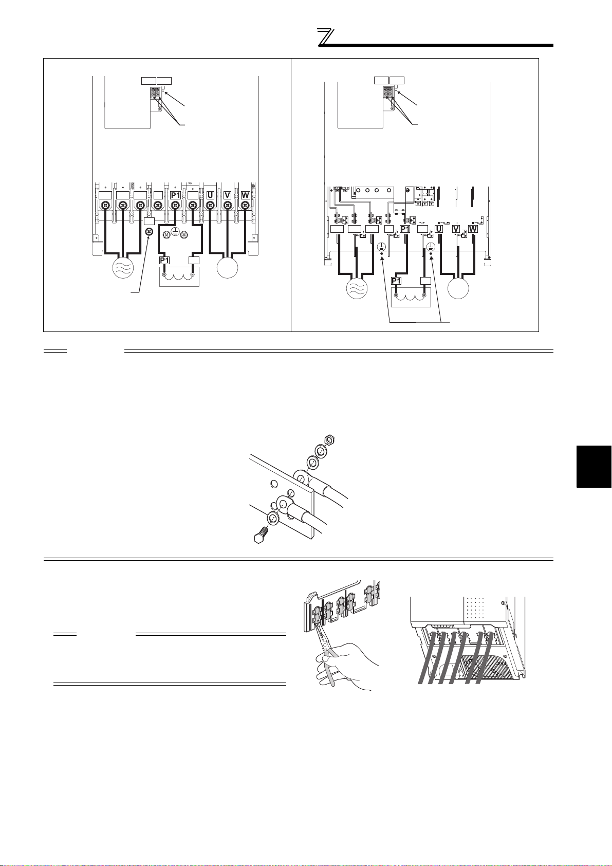
Main circuit terminal specifications
FR-F740P-132K to 220K FR-F740P-250K to 560K
R1/L11 S1/L21
Screw size (M4)
R1/L11 S1/L21
Screw size (M4)
Charge lamp
Jumper
Screw size (M12)
P/+
R/L1 S/L2 T/L3
Charge lamp
Jumper
Screw size
(M10 for 132K and 160K,
M12 for 185K and 220K)
N/-
P/+
P/+
Screw size
(M10)
P/+
R/L1 S/L2 T/L3
N/-
M
Power supply
Screw size (M12)
(for option)
DC reactor
Motor
Power supply
CAUTION
· The power supply cables must be connected to R/L1, S/L2, T/L3. (Phase sequence needs not to be matched.) Never connect
the power cable to the U, V, W of the inverter. Doing so will damage the inverter.
· Connect the motor to U, V, W. At this time, turning ON the forward rotation switch (signal) rotates the motor in the
counterclockwise direction when viewed from the motor shaft.
· When wiring the inverter main circuit conductor of the 250K or higher, tighten a nut from the right side of the conductor. When
wiring two wires, place wires on both sides of the conductor. (Refer to the drawing below.) For wiring, use bolts (nuts) provided
with the inverter.
P/+
M
Motor
DC reactor
Screw size (M10)
• Handling of the wiring cover
(FR-F720P-18.5K, 22K, FR-F740P-22K, 30K)
For the hook of the wiring cover, cut off the necessary
parts using a pair of long-nose pliers etc.
CAUTION
Cut off the same number of lugs as wires. If parts where
no wire is put through has been cut off (10mm or more),
protective structure (JEM1030) becomes an open type
(IP00).
2
WIRING
19

Main circuit terminal specifications
2.2.3 Cables and wiring length
(1) Applicable cable size
Select the recommended cable size to ensure that a voltage drop will be 2% or less.
If the wiring distance is long between the inverter and motor, a main circuit cable voltage drop will cause the motor
torque to decrease especially at the output of a low frequency.
The following table indicates a selection example for the wiring length of 20m.
200V class (when input power supply is 220V)
Cable Sizes
Earthing
cable
AWG/MCM *2
R/L1,
S/L2,
U, V, W
T/L3
PVC, etc. (mm2) *3
R/L1,
S/L2,
T/L3
U, V, W
Earthing
cable
Applicable
Inverter Model
FR-F720P-0.75K
to 2.2K
Terminal
Screw
Size *4
Tightening
Tor que
N·m
Terminal
R/L1,
S/L2,
T/L3
U, V, W
HIV, etc. (mm2) *1
R/L1,
S/L2,
U, V, W P/+, P1
T/L3
M4 1.5 2-4 2-4 2 2 2 2 14 14 2.5 2.5 2.5
Crimping
FR-F720P-3.7K M4 1.5 5.5-4 5.5-4 3.5 3.5 3.5 3.5 12 12 4 4 4
FR-F720P-5.5K M4 1.5 5.5-4 5.5-4 5.5 5.5 5.5 5.5 10 10 6 6 6
FR-F720P-7.5K M5 2.5 14-5 8-5 14 8 14 5.5 6 8 16 10 16
FR-F720P-11K M5 2.5 14-5 14-5 14 14 14 14 6 6 16 16 16
FR-F720P-15K M5 2.5 22-5 22-5 22 22 22 14 4 6 (
*5)25 25 16
FR-F720P-18.5K M6 4.4 38-6 38-6 38 38 38 22 2 2 35 35 25
FR-F720P-22K M8 (M6) 7.8 38-8 38-8 38 38 38 22 2 2 35 35 25
FR-F720P-30K M8 (M6) 7.8 60-8 60-8 60 60 60 22 1/0 1/0 50 50 25
FR-F720P-37K M8 (M6) 7.8 80-8 80-8 80 80 80 22 3/0 3/0 70 70 35
FR-F720P-45K
FR-F720P-55K
FR-F720P-75K
FR-F720P-90K
FR-F720P-110K
*1 The cable size is that of the cable (HIV cable (600V class 2 vinyl-insulated cable) etc.) with continuous maximum permissible temperature of
75°C. Assumes that the surrounding air temperature is 50°C or less and the wiring distance is 20m or less.
*2 The recommended cable size is that of the cable (THHW cable) with continuous maximum permissible temperature of 75°C. Assumes that the
surrounding air temperature is 40°C or less and the wiring distance is 20m or less.
(Selection example for use mainly in the United States.)
*3 For the 15K or lower, the recommended cable size is that of the cable (PVC cable) with continuous maximum permissible temperature of 70°C.
Assumes that the surrounding air temperature is 40°C or less and the wiring distance is 20m or less.
For the 18.5K or higher, the recommended cable size is that of the cable (XLPE cable) with continuous maximum permissible temperature of
90°C. Assumes that the surrounding air temperature is 40°C or less and wiring is performed in an enclosure.
(Selection example for use mainly in Europe.)
*4 The terminal screw size indicates the terminal size for R/L1, S/L2, T/L3, U, V, W, and a screw for earthing (grounding).
A screw for earthing (grounding) of the 22K or higher is indicated in ( ).
*5 When connecting the option unit to P/+, P1, N/-, use THHN cables for the option and terminals R/L1, S/L2, T/L3, U, V, W.
M10 (M8)
M10 (M8)
M12 (M10)
M12 (M10)
M12 (M10)
14.7 100-10 100-10 100 100 100 38 4/0 4/0 95 95 50
14.7 100-10 100-10 100 100 100 38 4/0 4/0 95 95 50
24.5 150-12 150-12 125 125 150 38 250 250 ⎯⎯ ⎯
24.5 150-12 150-12 150 150 2×100 38 2×4/0 2×4/0 ⎯⎯ ⎯
24.5 100-12 100-12 2×100 2×100 2×100 38 2×4/0 2×4/0 ⎯⎯⎯
20

Main circuit terminal specifications
400V class (when input power supply is 440V)
Crimping
Applicable
Inverter Model
FR-F740P-0.75K
to 3.7K
Ter min al
Screw
Tightening
Torque
Size *4
M4 1.5 2-4 2-4 2 2 2 2 14 14 2.5 2.5 2.5
(Compression)
N·m
Ter min al
R/L1,
S/L2,
T/L3
U, V, W
HIV, etc. (mm2) *1
R/L1,
S/L2,
U, V, W P/+, P1
T/L3
FR-F740P-5.5K M4 1.5 2-4 2-4 2 2 3.5 3.5 12 14 2.5 2.5 4
FR-F740P-7.5K M4 1.5 5.5-4 5.5-4 3.5 3.5 3.5 3.5 12 12 4 4 4
FR-F740P-11K M4 1.5 5.5-4 5.5-4 5.5 5.5 5.5 8 10 10 6 6 10
FR-F740P-15K M5 2.5 8-5 8-5 8 8 8 8 8 8 10 10 10
FR-F740P-18.5K M5 2.5 14-5 8-5 14 8 14 14 6 8 16 10 16
FR-F740P-22K M6 4.4 14-6 14-6 14 14 22 14 6 6 16 16 16
FR-F740P-30K M6 4.4 22-6 22-6 22 22 22 14 4 4 25 25 16
FR-F740P-37K M6 4.4 22-6 22-6 22 22 22 14 4 4 25 25 16
FR-F740P-45K M8 7.8 38-8 38-8 38 38 38 22 1 2 50 50 25
FR-F740P-55K M8 7.8 60-8 60-8 60 60 60 22 1/0 1/0 50 50 25
FR-F740P-75K M8 7.8 60-8 60-8 60 60 60 38 1/0 1/0 50 50 25
FR-F740P-90K M10 14.7 60-10 60-10 60 60 80 38 3/0 3/0 50 50 25
FR-F740P-110K M10 14.7 80-10 80-10 80 80 100 38 3/0 3/0 70 70 35
FR-F740P-132K M10 14.7 100-10 100-10 100 100 100 38 4/0 4/0 95 95 50
FR-F740P-160K M10 14.7 150-10 150-10 125 125 150 38 250 250 120 120 70
FR-F740P-185K
FR-F740P-220K
FR-F740P-250K
FR-F740P-280K
FR-F740P-315K
FR-F740P-355K
FR-F740P-400K
FR-F740P-450K
FR-F740P-500K
FR-F740P-560K
*1 For the FR-F740P-55K or lower, the recommended cable size is that of the cable (e.g. HIV cable (600V class 2 vinyl-insulated cable)) with continuous
maximum permissible temperature of 75°C. Assumes that the surrounding air temperature is 50°C or less and the wiring distance is 20m or less.
For the FR-F740P-75K or higher, the recommended cable size is that of the cable (e.g. LMFC (heat resistant flexible cross-linked polyethylene insulated
cable)) with continuous maximum permissible temperature of 90°C. Assumes that the surrounding air temperature is 50°C or less and wiring is performed
in an enclosure.
*2 For the FR-F740P-45K or lower, the recommended cable size is that of the cable (THHW cable) with continuous maximum permissible temperature of
75°C. Assumes that the surrounding air temperature is 40°C or less and the wiring distance is 20m or less.
For the FR-F740P-55K or higher, the recommended cable size is that of the cable (THHN cable) with continuous maximum permissible temperature of
90°C. Assumes that the surrounding air temperature is 40°C or less and wiring is performed in an enclosure.
(Selection example for use mainly in the United States.)
*3 For the FR-F740P-45K or lower, the recommended cable size is that of the cable (PVC cable) with continuous maximum permissible temperature of
70°C. Assumes that the surrounding air temperature is 40°C or less and the wiring distance is 20m or less.
For the FR-F740P-55K or higher, the recommended cable size is that of the cable (XLPE cable) with continuous maximum permissible temperature of
90°C. Assumes that the surrounding air temperature is 40°C or less and wiring is performed in an enclosure.
(Selection example for use mainly in the Europe.)
*4 The terminal screw size indicates the terminal size for R/L1, S/L2, T/L3, U, V, W
A screw for earthing (grounding) of the 185K or higher is indicated in ( ).
M12 (M10)
M12 (M10)
M12 (M10)
M12 (M10)
M12 (M10)
M12 (M10)
M12 (M10)
M12 (M10)
M12 (M10)
M12 (M10)
24.5 150-12 150-12 150 150 2×100 38 300 300 150 150 95
24.5 100-12 100-12 2×100 2×100 2×100 38 2×4/0 2×4/0 2×95 2×95 95
46 100-12 100-12 2×100 2×100 2×125 38 2×4/0 2×4/0 2×95 2×95 95
46 150-12 150-12 2×125 2×125 2×125 38 2×250 2×250 2×120 2×120 120
46 150-12 150-12 2×150 2×150 2×150 60 2×300 2×300 2×150 2×150 150
46 200-12 200-12 2×200 2×200 2×200 60 2×350 2×350 2×185 2×185 2×95
46 C2-200 C2-200 2×200 2×200 2×200 60 2×400 2×400 2×185 2×185 2×95
46 C2-250 C2-250 2×250 2×250 2×250 60 2×500 2×500 2×240 2×240 2×120
46 C2-250 C2-250 2×250 2×250 3×200 100 2×500 2×500 2×240 2×240 2×120
46 C2-200 C2-200 3×200 3×200 3×200 100 3×350 3×350 3×185 3×185 2×150
,
and a screw for earthing (grounding).
Cable Sizes
Earthing
cable
AWG/MCM *2
R/L1,
S/L2,
U, V, W
T/L3
PVC, etc. (mm2) *3
R/L1,
S/L2,
T/L3
U, V, W
Earthing
cable
2
WIRING
The line voltage drop can be calculated by the following formula:
Line voltage drop [V]=
3 × wire resistance[mΩ/m] × wiring distance[m] × current[A]
1000
Use a larger diameter cable when the wiring distance is long or when it is desired to decrease the voltage drop (torque
reduction) in the low speed range.
CAUTION
· Tighten the terminal screw to the specified torque.
A screw that has been tighten too loosely can cause a short circuit or malfunction.
A screw that has been tighten too tightly can cause a short circuit or malfunction due to the unit breakage.
· Use crimping terminals with insulation sleeve to wire the power supply and motor.
21

Main circuit terminal specifications
(2) Notes on earthing (grounding)
Always earth (ground) the motor and inverter.
1)Purpose of earthing (grounding)
Generally, an electrical apparatus has an earth (ground) terminal, which must be connected to the ground
before use.
An electrical circuit is usually insulated by an insulating material and encased. However, it is impossible to
manufacture an insulating material that can shut off a leakage current completely, and actually, a slight current
flow into the case. The purpose of earthing (grounding) the case of an electrical apparatus is to prevent
operator from getting an electric shock from this leakage current when touching it.
To avoid the influence of external noises, this earthing (grounding) is important to audio equipment, sensors,
computers and other apparatuses that handle low-level signals or operate very fast.
2)Earthing (grounding) methods and earthing (grounding) work
As described previously, earthing (grounding) is roughly classified into an electrical shock prevention type and a
noise-affected malfunction prevention type. Therefore, these two types should be discriminated clearly, and the
following work must be done to prevent the leakage current having the inverter's high frequency components
from entering the malfunction prevention type earthing (grounding):
(a) If possible, use (l) independent earthing (grounding) in figure below for the inverter. If independent earthing
(grounding) is not available, use (ll) joint earthing (grounding) in the figure below which the inverter is
connected with the other equipment at an earthing (grounding) point.
The (lll) common earthing (grounding) as in the figure below, which inverter shares a common earth
(ground) cable with the other equipment, must be avoided.
A leakage current including many high frequency components flows in the earth (ground) cables of the
inverter and inverter-driven motor. Therefore, use the independent earthing (grounding) and separated the
earthing (grounding) cable of the inverter from equipments sensitive to EMI.
In a high building, it may be effective to use the EMI prevention type earthing (grounding) connecting to an
iron structure frame, and electric shock prevention type earthing (grounding) with the independent earthing
(grounding) together.
(b) This inverter must be earthed (grounded). Earthing (Grounding) must conform to the requirements of
national and local safety regulations and electrical code (NEC section 250, IEC 536 class 1 and other
applicable standards).
A neutral-point earthed (grounded power supply for 400V class inverter in compliance with EN standard
must be used.
(c) Use the thickest possible earth (ground) cable. The earth
indicated in the above table on the previous page.
(d) The earthing (grounding) point should be as near as possible to the inverter, and the earthing (grounding)
wire length should be as short as possible.
(e) Run the earth (ground) cable as far away as possible from the I/O wiring of equipment sensitive to noises
and run them in parallel in the minimum distance.
(ground) cable should be of not less than the size
Inverter
(I) Independent earthing.......Best
Other
equipment
Inverter
(II) Joint earthing.......Good
Other
equipment
Inverter
(III) Joint earthing.......Not allowed
equipment
To be compliant with the EU Directive (Low Voltage Directive), refer to the Instruction Manual (Basic).
Other
22

Main circuit terminal specifications
(3) Total wiring length
Under general-purpose motor control
Connect one or more general-purpose motors within the total wiring length shown in the following table.
Pr. 72 PWM frequency selection Setting
(carrier frequency)
2 (2kHz) or lower 300m 500m 500m
3 (3kHz) or higher 200m 300m 500m
Total wiring length when using a general-purpose motor (2.2K or higher)
0.75K 1.5K 2.2K or Higher
300m
500m or less
300m + 300m = 600m
300m
When driving a 400V class motor by the inverter, surge voltages attributable to the wiring constants may occur at the
motor terminals, deteriorating the insulation of the motor. Take the following measures 1) or 2) in this case.
Refer to page 53 for measures against deteriorated insulation.
1) Use a "400V class inverter-driven insulation-enhanced motor" and set frequency in Pr. 72 PWM frequency selection
according to wiring length.
Wiring Length
50m or less 50m to 100m exceeding 100m
Pr. 72 PWM frequency selection Setting
(carrier frequency)
14.5kHz or lower 9kHz or lower 4kHz or lower
2) Connect the surge voltage suppression filter (FR-ASF-H/FR-BMF-H) to the 55K or lower and the sine wave filter
(MT-BSL/BSC) to the 75K or higher on the inverter output side.
zUnder IPM motor control
Connect an IPM motor within the total wiring length of 100m.
Use one dedicated IPM motor for one inverter. Multiple IPM motors cannot be connected to an inverter.
To drive a 400V-class motor with an inverter under IPM control, set Pr.72 PWM frequency selection according to the wiring
length as shown below.
Applied inverter
FR-F740P-0.75K to 1.5K 0(2kHz) to 15(14kHz) 5(2kHz) or lower
Other 0(2kHz) to 15(14kHz) 9(6kHz) or lower
50m or less 50m to 100m
Wiring Length
CAUTION
· Especially for long-distance wiring, the inverter may be affected by a charging current caused by the stray capacitances of the
wiring, leading to a malfunction of the overcurrent protective function or fast response current limit function or a malfunction or fault
of the equipment connected on the inverter output side. If fast-response current limit function malfunctions, disable this function.
(For Pr.156 Stall prevention operation selection, refer to page 91 .)
· For details of Pr. 72 PWM frequency selection , refer to page 182 . (When using an optional sine wave filter (MT-BSL/BSC) for
the 75K or higher, set "25" in Pr.72 (2.5kHz).
· The surge voltage suppression filter (FR-ASF-H/FR-BMF-H) option and sine wave filter (MT-BSL/BSC) cannot be used under
IPM motor control, so do not connect them.
· For explanation of surge voltage suppression filter (FR-ASF-H/FR-BMF-H) and sine wave filter (MT-BSL/BSC), refer to the
manual of each option.
(Sine wave filter can be only used with a general-purpose motor.)
(4) Cable size of the control circuit power supply (terminal R1/L11, S1/L21)
· Terminal Screw Size: M4
· Cable size: 0.75mm
· Tightening torque: 1.5N·m
2
to 2mm
2
2
WIRING
23

Main circuit terminal specifications
2.2.4 When connecting the control circuit and the main circuit separately to the power supply
<Connection diagram> When fault occurs, opening of the electromagnetic contactor (MC) on the
MC
Inverter
R/L1
S/L2
T/L3
R1/L11
S1/L21
Remove the jumper
• FR-F720P-0.75K to 5.5K, FR-F740P-0.75K to 5.5K
inverter power supply side results in power loss in the control circuit,
disabling the fault output signal retention. Terminals R1/L11 and S1/L21 are
provided for when retention of a fault signal is required. In this case, connect
the power supply terminals R1/L11 and S1/L21 of the control circuit to the
primary side of the MC.
Do not connect the power cable to incorrect terminals. Doing so may
damage the inverter.
1)Loosen the upper screws.
2)Remove the lower screws.
3)
3)Remove the jumper
4)Connect the separate power
supply cable for the control
circuit to the lower terminals
1)
(R1/L11, S1/L21).
2)
4)
R1/L11
Main circuit terminal block
• FR-F720P-7.5K, 11K, FR-F740P-7.5K, 11K
1)Remove the upper screws.
2)Remove the lower screws.
3)Remove the jumper.
4)Connect the separate power
supply cable for the control
circuit to the upper terminals
(R1/L11, S1/L21).
R/L1
S1/L21
3)
1)
2)
S/L2
T/L3
R1/L11
S1/L21
R1/L11
S1/L21
R1/L11
S1/L21
24
4)
R/
S/
L1
T/
L2
L3
Main circuit
terminal block

• FR-F720P-15K, FR-F740P-15K or higher
1)Remove the upper screws.
2)Remove the lower screws.
3)Pull the jumper toward you to
remove.
Connect the separate power supply
4)
cable for the control circuit to the
upper terminals (R1/L11, S1/L21)
.
MC
R/L1
S/L2
T/L3
R1/
L11
S1/
L21
Power supply
terminal block
for the control circuit
Main circuit terminal specifications
3)
Power supply terminal block
for the control circuit
R1/L11
S1/L21
Main power supply
Power supply
terminal block for
the control circuit
FR-F720P-15K
FR-F740P-15K, 18.5K
FR-F720P-18.5K to 30K
FR-F740P-22K, 30K
1)
2)
4)
FR-F720P-37K or higher
FR-F740P-37K or higher
VUW
CAUTION
· Be sure to use the inverter with the jumpers across terminals R/L1 and R1/L11, and S/L2 and S1/L21 removed when supplying
power from other sources. The inverter may be damaged if you do not remove the jumper.
· The voltage should be the same as that of the main control circuit when the control circuit power is supplied from other than the
primary side of the MC.
· The power capacity necessary when separate power is supplied from R1/L11 and S1/L21 differs according to the inverter
capacity.
15K or lower 18.5K 22K or higher
200V class 60VA 80VA 80VA
400V class 60VA 60VA 80VA
· If the main circuit power is switched OFF (for 0.1s or more) then ON again, the inverter resets and a fault output will not be held.
2
WIRING
25

Control circuit specifications
2.3 Control circuit specifications
2.3.1 Control circuit terminals
indicates that terminal functions can be selected using Pr. 178 to Pr. 196 (I/O terminal function selection) (Refer to page 133.)
(1) Input signals
Terminal
Symbol
Type
STF
STR
STOP
RH,
RM, RL
JOG
RT
MRS Output stop
RES Reset
AU
Contact input
CS
SD
PC
Ter minal
Name
Forward
rotation start
Reverse
rotation start
Start s elf holding
selection
Multi-speed
selection
Jog mode
selection
Second
function
selection
Terminal 4
input selection
PTC input
Selection of
automatic
restart after
instantaneous
power failure
Contact input
common (sink)
(initial setting)
External
transistor
common
(source)
24VDC power
supply common
External
transistor
common (sink)
(initial setting)
Contact input
common
(source)
24VDC power
supply
Description
Turn ON the STF signal to start forward
rotation and turn it OFF to stop.
Turn ON the STR signal to start reverse
rotation and turn it OFF to stop.
Turn ON the STOP signal to self-hold the start signal. 133
Multi-speed can be selected according to the combination of RH,
RM and RL signals.
Turn ON the JOG signal to select Jog operation (initial setting)
and turn ON the start signal (STF or STR) to start Jog operation.
Turn ON the RT signal to select second function.
When the second function such as "second torque boost" and
"second V/F (base frequency)" are set, turning ON the RT signal
selects these functions.
Turn ON the MRS signal (20ms or more) to stop the inverter
output.
Use to shut off the inverter output when stopping the motor by
electromagnetic brake.
Use to reset fault output provided when fault occurs.
Turn ON the RES signal for more than 0.1s, then turn it OFF.
In the initial status, reset is set always-enabled. By setting Pr.75,
reset can be set enabled only at fault occurrence. Inverter
recovers about 1s after the reset is released.
Terminal 4 is valid only when the AU signal is turned ON. (The
frequency setting signal can be set between 0 and 20mADC.)
Turning the AU signal ON makes terminal 2 (voltage input)
invalid.
AU terminal is used as PTC input terminal (thermal protection of
the motor). When using it as PTC input terminal, set the AU/PTC
switch to PTC.
ON
When the CS signal is left
power restoration. Note that restart setting is necessary for this
operation. In the initial setting, a restart is disabled.
(Refer to Pr. 57 Restart coasting time page
Common terminal for contact input terminal (sink logic) and terminal
FM.
Connect this terminal to the power supply common terminal of a
transistor output (open collector output) device, such as a
programmable controller, in the source logic to avoid malfunction by
undesirable currents.
Common output terminal for 24VDC 0.1A power supply (PC terminal).
Isolated from terminals 5 and SE.
Connect this terminal to the power supply common terminal of a
transistor output (open collector output) device, such as a
programmable controller, in the sink logic to avoid malfunction by
undesirable currents.
Common terminal for contact input terminal (source logic).
Can be used as 24VDC 0.1A power supply.
, the inverter restarts automatically at
When the STF and
STR signals are turned
ON simultaneously, the
stop command is given.
162
)
Rated
Specifications
Input resistance
4.7kΩ
Voltage at
opening: 21 to
27VDC
Contacts at
short-circuited: 4
to 6mADC
-------------- ------ —
Power supply
voltage range
19.2 to 28.8VDC
Permissible load
current 100mA
Refer to
Page
133
133
133
133
133
133
185
121
133
30
26

Control circuit specifications
Terminal
Symbol
Type
Terminal
Name
Description
Rated
Specifications
10VDC±0.4V
10E
10
Frequency
setting power
supply
When connecting the frequency setting potentiometer at an initial
status, connect it to terminal 10.
Change the input specifications of terminal 2 when connecting it
to terminal 10E. (Refer to Pr. 73 Analog input selection inpage 191.)
Permissible load
current 10mA
5.2VDC±0.2V
Permissible load
current 10mA
Voltage input:
Input resistance
Inputting 0 to 5VDC (or 0 to 10V, 0 to 20mA) provides the
2
setting
(voltage)
Frequency
maximum output frequency at 5V (10V, 20mA) and makes input
and output proportional. Use Pr. 73 to switch from among input 0
to 5VDC (initial setting), 0 to 10VDC, and 0 to 20mA.
Set the voltage/current input switch in the ON position to select
current input (0 to 20mA).
*1
10kΩ ± 1kΩ
Maximum
permissible
voltage 20VDC
Current input:
Input resistance
245Ω ± 5Ω
Maximum
permissible
current 30mA
Voltage/current
input switch
2
4
Frequency setting
Inputting 4 to 20mADC (or 0 to 5V, 0 to 10V) provides the
Frequency
4
setting
(current)
maximum output frequency at 20mA (5V, 10V) makes input and
output proportional. This input signal is valid only when the AU
signal is ON (terminal 2 input is invalid). Use Pr. 267 to switch
from among input 4 to 20mA (initial setting), 0 to 5VDC, and 0 to
10VDC. Set the voltage/current input switch in the OFF position
to select voltage input (0 to 5V/0 to 10V).
*1
Switch 1
Switch 2
Input resistance
Frequency
1
setting
auxiliary
Inputting 0 to ±5 VDC or 0 to ±10VDC adds this signal to terminal
2 or 4 frequency setting signal. Use Pr.73 to switch between the
input 0 to ±5VDC and 0 to ±10VDC (initial setting).
10kΩ ± 1kΩ
Maximum
permissible voltage
± 20VDC
Frequency
5
setting
common
*1 Set Pr. 73, Pr. 267, and a voltage/current input switch correctly, then input an analog signal in accordance with the setting.
Applying a voltage signal with voltage/current input switch ON (current input is selected) or a current signal with switch OFF (voltage input is
selected) could cause component damage of the inverter or analog circuit of signal output devices. (For details, refer to page 185.)
Common terminal for frequency setting signal (terminal 2, 1 or 4)
and analog output terminal AM. Do not earth (ground).
-------------- ------ 1 8 5
Refer to
Page
185
185
185
185
185
2
27
WIRING

Control circuit specifications
(2) Output signals
Terminal
Symbol
Type
A1,
B1,
C1
Relay
A2,
B2,
C2
RUN
SU
OL
Open collector
IPF
FU
SE
FM For meter
Pulse
AM
Analog
Terminal
Relay output 1
(Fault output)
Relay output 2 1 changeover contact output 140
Inverter
running
Up to
frequency
Overload
warning
Instantaneous
power failure
Frequency
detection
Open collector
output common
Analog signal
output
Name
Refer
Description Rated Specifications
Page
1 changeover contact output indicates that the
inverter’s protective function has activated and the
output stopped.
Fault: No conduction between B and C (conduction
between A and C)
Normal: Conduction between B and C (No conduction
between A and C)
Switched low when the inverter output frequency is
equal to or higher than the starting frequency (initial
value 0.5Hz). Switched high during stop or DC
injection brake operation.
Switched low when the output
frequency reaches within the range
of ±10% (initial value) of the set
frequency. Switched high during
acceleration/deceleration and at a
stop.
Switched low when stall prevention is
activated by the stall prevention
function. Switched high when stall
prevention is cancelled.
Switched low when an instantaneous
power failure and under voltage
protections are activated.
Switched low when the inverter
output frequency is equal to or higher
than the preset detected frequency
and high when less than the preset
detected frequency.
C o m m o n t e r m i n a l f o r t e r m i n a l s R U N , S U , O L , I P F, F U -------------------- -----
Select one e.g. output frequency
from monitor items. (Not output
during inverter reset.)
The output signal is proportional to
the magnitude of the corresponding
monitoring item.
To set a full-scale value for
monitoring the output frequency and
the output current, set Pr.56 and
Pr.158.
Alarm code
(4bit) output
Output item:
Output
frequency
(initial setting)
Output item:
Output
frequency
(initial setting)
Contact capacity: 230VAC 0.3A
(Power factor=0.4)
30VDC 0.3A
Permissible load 24VDC
(27VDC maximum) 0.1A
(A voltage drop is 3.4V
maximum when the signal is
ON.)
Low is when the open collector
output transistor is ON
(conducts).
High is when the transistor is
OFF (does not conduct).
Permissible load current 2mA
1440 pulse/s at 60Hz (generalpurpose motor control)
1440 pulse/s at 90Hz (IPM motor
control with 30K or lower)
1440 pulse/s at 120Hz (IPM
motor control with 37K or higher)
Output signal 0 to 10VDC
Permissible load current 1mA
(load impedance 10kΩ or
more) Resolution 8 bit
140
140
140
140
140
140
157
157
to
(3) Communication
Type
RS-485
Terminal
Symbol
—
TXD+
TXD-
RXD+
RXD-
RS-485 terminals
SG
Terminal
Name
PU
connector
Inverter
transmission
terminal
Inverter
reception
terminal
Earth (Ground)
28
Description
With the PU connector, communication can be established through RS-485.
(for connection on a 1:1 basis only)
Conforming standard : EIA-485 (RS-485)
Transmission format : Multidrop link
Communication speed : 4800 to 38400bps
Overall length : 500m
With the RS-485 terminals, communication can be established through RS-485.
Conforming standard : EIA-485 (RS-485)
Transmission format : Multidrop link
Communication speed : 300 to 38400bps
Overall length : 500m
Refer to
Page
224
226

Control circuit specifications
2.3.2 Changing the control logic
The input signals are set to sink logic (SINK) when shipped from the factory.
To change the control logic, the jumper connector on the back of the control circuit terminal block must be moved to the
other position.
(The output signals may be used in either the sink or source logic independently of the jumper connector position.)
1) Loosen the two installation screws in both ends of the control circuit terminal block. (These screws cannot be
removed.)
Pull down the terminal block from behind the control circuit terminals.
2) Change the jumper connector set to the sink logic (SINK) on the rear panel of the control circuit terminal block to
source logic (SOURCE).
Jumper connector
3) Using care not to bend the pins of the inverter's control circuit connector, reinstall the control circuit terminal block
and fix it with the mounting screws.
CAUTION
1. Make sure that the control circuit connector is fitted correctly.
2. While power is on, never disconnect the control circuit terminal block.
2
WIRING
29

Control circuit specifications
r
4)Sink logic and source logic
⋅ In sink logic, a signal switches ON when a current flows from the corresponding signal input terminal.
Terminal SD is common to the contact input signals. Terminal SE is common to the open collector output signals.
⋅ In source logic, a signal switches ON when a current flows into the corresponding signal input terminal.
Terminal PC is common to the contact input signals. Terminal SE is common to the open collector output signals.
Current flow concerning the input/output signal
when sink logic is selected
Sink logic
Current
STF
STR
SD
Inverter
RUN
SE
R
R
TB1
-
+
TB17
24VDC
Current flow
DC input (sink type)
<Example: QX40>
R
R
Sink
connector
Current flow concerning the input/output signal
when source logic is selected
Source logic
PC
Current
STF
R
STR
R
Inverter
RUN
SE
+
24VDC
Current flow
DC input (source type)
<Example: QX80>
TB1
R
-
TB18
Source
connecto
R
• When using an external power supply for transistor output
⋅ Sink logic type
Use terminal PC as a common terminal, and perform
wiring as shown below. (Do not connect terminal SD of
the inverter with terminal 0V of the external power
supply. When using terminals PC and SD as a 24VDC
power supply, do not install a power supply in parallel in
the outside of the inverter. Doing so may cause a
malfunction due to undesirable current.)
QY40P type transistor
output unit
Constant
voltage
circuit
TB1
TB2
TB17
TB18
STF
STR
24VDC
Inverter
24VDC
(SD)
PC
SD
Current flow
⋅ Source logic type
Use terminal SD as a common terminal, and perform
wiring as shown below. (Do not connect terminal PC of
the inverter with terminal +24V of the external power
supply. When using terminals PC and SD as a 24VDC
power supply, do not install an external power supply in
parallel with the inverter. Doing so may cause a
malfunction in the inverter due to undesirable currents.)
QY80 type transistor
output unit
Constant
voltage
circuit
Fuse
TB1
TB2
TB17
TB18
Current flow
PC
STF
STR
24VDC
SD
Inverter
24VDC
(SD)
30

2.3.3 Control circuit terminal layout
Control circuit specifications
A1 B1 C1 A2
RUN
SE
OLIPFSU
B2 C2
AURTRHRMRL
10E
10
STOP
RES
MRS
STF
SDSDFU PCCS
254
SD
JOG
STR
Terminal screw size: M3.5
Tightening torque: 1.2N·m
1
AMFM
(1) Common terminals of the control circuit (SD, 5, SE)
Control circuit terminal
Terminals SD, 5, and SE are all common terminals (0V) for I/O signals and are isolated from each other. Do not
earth(ground) these terminals.
Avoid connecting the terminal SD and 5 and the terminal SE and 5.
Terminal SD is a common terminal for the contact input terminals (STF, STR, STOP, RH, RM, RL, JOG, RT, MRS, RES,
AU, CS) and frequency output signal (FM).
The open collector circuit is isolated from the internal control circuit by photocoupler.
Terminal 5 is a common terminal for frequency setting signal (terminal 2, 1 or 4) and analog output terminal AM.
It should be protected from external noise using a shielded or twisted cable.
Terminal SE is a common terminal for the open collector output terminal (RUN, SU, OL, IPF, FU).
The contact input circuit is isolated from the internal control circuit by photocoupler.
(2) Signal inputs by contactless switches
The contacted input terminals of the inverter (STF, STR, STOP,
RH, RM, RL, JOG, RT, MRS, RES, AU, CS) can be controlled
using a transistor instead of a contacted switch as shown on the
right.
External signal input using transistor
+24V
STF, etc
Inverter
SD
2.3.4 Wiring instructions
1) It is recommended to use the cables of 0.75mm2 gauge for connection to the control circuit terminals.
If the cable gauge used is 1.25mm
the cables are run improperly, resulting in an operation panel contact fault.
2) The maximum wiring length should be 30m (200m for terminal FM).
3) Use two or more parallel micro-signal contacts or twin contacts to
prevent a contact faults when using contact inputs since the
control circuit input signals are micro-currents.
4) Use shielded or twisted cables for connection to the control circuit terminals and run them away from the main and
power circuits (including the 200V relay sequence circuit).
5) Do not apply a voltage to the contact input terminals (e.g. STF) of the control circuit.
6) Always apply a voltage to the fault output terminals (A, B, C) via a relay coil, lamp, etc.
2
or more, the front cover may be lifted when there are many cables running or
Micro signal contacts Twin contacts
2
WIRING
31

Control circuit specifications
z Wiring of the control circuit of the 75K or higher
For wiring of the control circuit of the 75K or higher, separate away from wiring of the main circuit.
Make cuts in rubber bush of the inverter side and lead wires.
<Wiring>
Rubber bush
(view from the inside)
Make cuts along the lines inside with
a cutter knife and such.
2.3.5 Mounting the operation panel (FR-DU07) on the enclosure surface
Having an operation panel on the enclosure surface is convenient. With a connection cable, you can mount the
operation panel (FR-DU07) to the enclosure surface, and connect it to the inverter.
Use the option FR-CB2, or the following connector and cable available on the market.
Securely insert one end of connection cable into the PU connector of the inverter and the other end into the
connection connector of the operation panel (FR-DU07) along the guides until the stoppers are fixed.
Parameter unit connection cable
(FR-CB2)(option)
Operation panel(FR-DU07)
Operation panel connection connector
(FR-ADP)(option)
CAUTION
Do not connect the cable to a LAN port of a personal computer, to a fax modem socket, or to a telephone connector. Doing so may
damage the inverter and the connected device due to the differences in the electric specifications.
32

2.3.6 RS-485 terminal block
⋅ Conforming standard: EIA-485(RS-485)
⋅ Transmission format: Multidrop link
⋅ Communication speed: MAX 38400bps
⋅ Overall length: 500m
⋅ Connection cable:Twisted pair cable
(4 pairs)
OPEN
100Ω
TXD
RDA1
(RXD1+)
(RXD1-)
SDA1
(TXD1+)
Control circuit specifications
Terminating resistor switch
Factory-set to "OPEN".
Set only the terminating resistor switch of
the remotest inverter to the "100Ω" position.
RDB1
RDA2
RDB2
SDB2
(TXD2-)
RXD
(RXD2+)
SDB1
(TXD1-)
(RXD2-)
SDA2
(TXD2+)
P5S
(VCC)SG(GND)
P5S
(VCC)SG(GND)
VCC
2.3.7 Communication operation
Using the PU connector or RS-485 terminal, you can perform communication operation from a personal computer etc.
When the PU connector is connected with a personal, FA or other computer by a communication cable, a user program
can run and monitor the inverter or read and write to parameters.
For the Mitsubishi inverter protocol (computer link operation), communication can be performed with the PU connector
and RS-485 terminal.
For the Modbus-RTU protocol, communication can be performed with the RS-485 terminal.
For further details,
refer to page 224.
2
WIRING
33

Connection of stand-alone option units
r
2.4 Connection of stand-alone option units
The inverter accepts a variety of stand-alone option units as required.
Incorrect connection will cause inverter damage or accident. Connect and operate the option unit carefully in
accordance with the corresponding option unit manual.
2.4.1 Connection of the brake unit (FR-BU2)
Connect the brake unit (FR-BU2) as shown below to improve the braking capability at deceleration.
(1) Connection example with the GRZG type discharging resistor
OCR contact
OFFON
*2
Three-phase AC
power supply
MCCB
MC
R/L1
S/L2
T/L3
Inverter
T
MC
U
V
Motor
M
OCR
External thermal
relay
W
*3
P/+
N/-
*1
10m or less
*3
MC
GRZG type
discharging resistor
RR
*4
FR-BU2
PR
P/+
N/-
A
B
C
BUE
SD
*5
*1 Connect the inverter terminals (P/+, N/-) and brake unit (FR-BU2) terminals so that their terminal names match with each other.
(Incorrect connection will damage the inverter and brake unit.)
*2 When the power supply is 400V class, install a step-down transformer.
*3 Keep a wiring distance of within 5m between the inverter, brake unit (FR-BU2) and discharging resistor. Even when the wiring
is twisted, the cable length must not exceed 10m. When twisting, twist at least 5 times per meter.
The brake unit may be damaged if cables are not twisted when the wiring length is 5m or more or the wiring length exceeds
10m or more even if cables are twisted.
*4 It is recommended to install an external thermal relay to prevent overheat of discharging resistors.
*5
Refer to FR-BU2 manual for connection method of discharging resistor.
<Recommended external thermal relay>
Brake Unit Discharging Resistor Recommended External Thermal Relay
FR-BU2-1.5K
FR-BU2-3.7K
FR-BU2-7.5K
FR-BU2-15K
FR-BU2-H7.5K
FR-BU2-H15K
FR-BU2-H30K
GZG 300W-50Ω (one)
GRZG 200-10Ω (three in series)
GRZG 300-5Ω (four in series)
GRZG 400-2Ω (six in series)
GRZG 200-10Ω (six in series)
GRZG 300-5Ω (eight in series)
GRZG 400-2Ω (twelve in series)
TH-N20CXHZ 1.3A
TH-N20CXHZ 3.6A
TH-N20CXHZ 6.6A
TH-N20CXHZ 11A
TH-N20CXHZ 3.6A
TH-N20CXHZ 6.6A
TH-N20CXHZ 11A
CAUTION
⋅ Set "1" in Pr. 0 Brake mode selection of the FR-BU2 to use GRZG type discharging resistor.
⋅ Do not remove a jumper across terminal P/+ and P1 except when connecting a DC reactor.
1/L1 5/L3
2/T1 6/T3
To the brake
unit terminal P/+
TH-N20
To a resisto
34

(2) FR-BR-(H) connection example with resistor unit
*2
T
Connection of stand-alone option units
OFFON
MC
MC
MCCB
Three phase AC
power supply
MC
R/L1
S/L2
T/L3
U
V
W
Motor
M
*3
Inverter
P/+
N/-
*1 Connect the inverter terminals (P/+, N/-) and brake unit (FR-BU2) terminals so that their terminal names match with each other.
(Incorrect connection will damage the inverter and brake unit.)
*2 When the power supply is 400V class, install a step-down transformer.
*3 The wiring distance between the inverter, brake unit (FR-BU) and resistor unit (FR-BR) should be within 5m. Even when the
wiring is twisted, the cable length must not exceed 10m.
*4 The contact between TH1 and TH2 is closed in the normal status and is open at a fault.
*1
10m or less
*3
CAUTION
⋅ Do not remove a jumper across terminal P/+ and P1 except when connecting a DC reactor.
(3) Connection example with MT-BR5 type resistor unit
After making sure that the wiring is correct, set the following parameters:
⋅ Pr. 30 Regenerative function selection = "1"
⋅ Pr. 70 Special regenerative brake duty = "0 (initial value)"
Set Pr. 0 Brake mode selection = "2" in the brake unit FR-BU2.
*2
T
FR-BR
P
TH1
PR
TH2
FR-BU2
PR
P/+
N/BUE
SD
*4
A
B
C
2
OFFON
10m
or less
CR1
MC
*3
TH1
P
PR
TH2
Resistor unit
MT-BR5
CR1
*4
MCCB
Three phase AC
power supply
*1 Connect the inverter terminals (P/+, N/-) and brake unit (FR-BU2) terminals so that their terminal names match with each other.
(Incorrect connection will damage the inverter and brake unit.)
*2 When the power supply is 400V class, install a step-down transformer.
*3 The wiring distance between the inverter, brake unit (FR-BU2) and resistor unit (MT-BR5) should be within 5m. If twisted wires
are used, the distance should be within 10m.
*4 The contact between TH1 and TH2 is open in the normal status and is closed at a fault.
*5 CN8 connector used with the MT-BU5 type brake unit is not used.
MC
R/L1
S/L2
W
T/L3
P/+
N/-
Inverter
Motor
U
V
M
*1
*3
*5
MC
P
N
PR
BUE
SD
Brake unit
FR-BU2
P
CAUTION
⋅ The stall prevention (overvoltage), oL, does not occur while Pr. 30 Regenerative function selection = "1" and Pr. 70 Special
regenerative brake duty = "0% (initial setting)."
♦ Parameters referred to ♦
Pr.30 Regenerative function selection Refer to page 125
Pr.70 Special regenerative brake duty Refer to page 125
WIRING
35

Connection of stand-alone option units
2.4.2 Connection of the brake unit (FR-BU/MT-BU5)
When connecting the brake unit (FR-BU(H)/MT-BU5) to improve the brake capability at deceleration, make connection
as shown below.
(1) Connection with the FR-BU (55K or lower)
OFFON
T *2
MC
MCCB
Three-phase AC
power supply
*1 Connect the inverter terminals (P/+, N/-) and brake unit (FR-BU (H)) terminals so that their terminal signals match
with each other. (Incorrect connection will damage the inverter.)
*2 When the power supply is 400V class, install a step-down transformer.
*3 The wiring distance between the inverter, brake unit (FR-BU) and resistor unit (FR-BR) should be within 5m. If
twisted wires are used, the distance should be within 10m.
MC
R/L1
S/L2
T/L3
Inverter
U
V
W
P/+
N/−
MC
Motor
M
*1
*3
10m or less
FR-BR
P
PR
FR-BU
PR
P/+
N/−
TH1
TH2
HA
HB
HC
CAUTION
⋅ If the transistors in the brake unit should become faulty, the resistor can be unusually hot, causing a fire. Therefore, install a
magnetic contactor on the inverter’s input side to configure a circuit so that a current is shut off in case of fault.
⋅ Do not remove a jumper across terminal P/+ and P1 except when connecting a DC reactor.
36

Connection of stand-alone option units
A
(2) Connection with the MT-BU5 (75K or higher)
After making sure that the wiring is correct, set the following parameters:
⋅ Pr. 30 Regenerative function selection = "1"
⋅ Pr. 70 Special regenerative brake duty = "10%"
T *1
OFFON
MCCB
Three-phase
C power
supply
*1 When the power supply is 400V class, install a step-down transformer.
*2 The wiring length between the resistor unit and brake resistor should be 10m maximum when wires are
twisted and 5m maximum when wires are not twisted.
MC
R/L1
S/L2
T/L3
Inverter
CN8
P/+
N/
U
V
W
Motor
M
P
PR
P
PR
Brake unit
MT-BU5
MC
10m or
less
*2
CAUTION
⋅ Install the brake unit in a place where a cooling air reaches the brake unit heatsink and within a distance of the cable supplied
with the brake unit reaches the inverter.
⋅ For wiring of the brake unit and inverter, use an accessory cable supplied with the brake unit. Connect the main circuit cable to
the inverter terminals P/+ and N/- and connect the control circuit cable to the CN8 connector inside by making cuts in the
rubber bush at the top of the inverter for leading the cable.
⋅ The brake unit which uses multiple resistor units has terminals equal to the number of resistor units. Connect one resistor unit
to one pair of terminal (P, PR).
<Inserting the CN8 connector>
Make cuts in rubber bush of the upper portion of the inverter and lead a cable.
1) Make cuts in the rubber bush for leading the CN8 connector cable with a nipper or cutter knife.
Rubber bushes
CR1 CR2
P
PR
P
PR
Resistor unit
MT-BR5
MC
TH1
TH2
TH1
TH2
CR1
CR2
2
WIRING
Make cuts in
rubber bush
2) Insert a connector on the MT-BU5 side through a rubber bush to connect to a connector on the inverter side.
CN8 connector
Wire clamp
CAUTION
Clamp the CN8 connector cable on the inverter side with a wire clamp securely.
♦ Parameters referred to ♦
Pr.30 Regenerative function selection Refer to page 125
Pr.70 Special regenerative brake duty Refer to page 125
Insert the connector until
you hear a click sound.
37

Connection of stand-alone option units
A
A
r
2.4.3 Connection of the brake unit (BU type)
Connect the brake unit (BU type) correctly as shown below. Incorrect connection will damage the inverter. Remove the jumper
across terminals HB and PC and terminals TB and HC of the brake unit and fit it to across terminals PC and TB.
OFFON
T*1
MC
Three-phase
C power
supply
MCCB
MC
R/L1
S/L2
T/L3
Inverter
W
N/-
P/+
Motor
U
V
M
MC
Brake unit
(BU type)
N
OCR
Remove the
jumper
TB
HC
HB
Discharging
resistor
OCR
PR
HA
PC
Fit a jumper
P
*1 When the power supply is 400V class, install a step-down transformer.
CAUTION
⋅ The wiring distance between the inverter, brake unit and discharging resistor should be within 2m. If twisted wires are used, the
distance should be within 5m.
⋅ If the transistors in the brake unit should become faulty, the resistor can be unusually hot, causing a fire. Therefore, install a
magnetic contactor on the inverter's power supply side to shut off a current in case of fault.
⋅ Do not remove a jumper across terminal P/+ and P1 except when connecting a DC reactor.
2.4.4 Connection of the high power factor converter (FR-HC/MT-HC)
When connecting the high power factor converter (FR-HC/MT-HC) to suppress power harmonics, perform wiring securely as
shown below. Incorrect connection will damage the high power factor converter and inverter.
After making sure that the wiring is correct, set "2" in Pr. 30 Regenerative function selection. (Refer to page 125.)
(1) Connection with the FR-HC (55K or lower)
High power factor converter
Reactor2
(FR-HCL02)
R3
R4
S4
S3
T4
T3
(FR-HC)(FR-HCB)
MC1
MC2
R4
S4
T4
R
phase
S
detection
T
Y1orY2
RDY
RSO
SE
Inverter
R/L1
*1
S/L2
T/L3
P
N
P/+
*2
N/X11
*4
*3
X10
*3
RES
SD
R1/L11
S1/L21
*1
Moto
U
V
W
M
Three-phase
C power
supply
MCCB
MC
Reactor1
(FR-HCL01)
R2
R
S2
S
T
T2
Outside box
R2
S2
T2
MC1
MC2
R3
S3
T3
*1 Remove the jumpers across the inverter terminals R/L1 and R1/L11 and terminals S/L2 and S1/L21, and connect the control circuit power supply
to the R1/L11 and S1/L21 terminals. Do not connect anything to the power input terminals R/L1, S/L2, and T/L3. Incorrect connection will damage
the inverter. (E.OPT (option fault) will occur. (Refer to page 318.))
*2 Do not insert the MCCB between terminals P/+ and N/- (P/+ and P/+, N/- and N/-). Opposite polarity of terminals N/-, P/+ will damage the inverter.
*3 Use Pr. 178 to Pr. 189 (input terminal function selection) to assign the terminals used for the X10 (X11) signal. (Refer to page 133.)
For communication where the start command is sent only once, e.g. RS-485 communication operation, use the X11 signal when making setting to
hold the mode at occurrence of an instantaneous power failure. (Refer to page 125.)
*4 Be sure to connect terminal RDY of the FR-HC to the X10 signal or MRS signal assigned terminal of the inverter, and connect terminal SE of the
FR-HC to terminal SD of the inverter. Without proper connecting, FR-HC will be damaged.
CAUTION
⋅ The voltage phases of terminals R/L1, S/L2, T/L3 and terminals R4, S4, T4 must be matched.
⋅ Use sink logic (initial setting) when the FR-HC is connected. The FR-HC cannot be connected when source logic is selected.
⋅ Do not connect a DC reactor to the inverter when FR-HC is connected.
⋅ Do not remove a jumper across terminal P/+ and P1.
38

(2) Connection with the MT-HC (75K or higher)
A
Connection of stand-alone option units
Three-phase
C power
supply
MCCB
*1 Remove the jumper across terminals R and R1, S and S1 of the inverter, and connect the control circuit
*2 Do not insert the MCCB between terminals P/+ and N/- (P/+ and P/+, N/- and N/-). Opposite polarity of
*3 Use Pr. 178 to Pr. 189 (input terminal function selection) to assign the terminals used for the X10 (X11) signal.
*4 Connect the power supply to terminals R1 and S1 of the MT-HC via an isolated transformer.
*5 Be sure to connect terminal RDY of the MT-HC to the X10 signal or MRS signal assigned terminal of the
MC
power supply to the R1 and S1 terminals. Do not connect anything to the power input terminals R/L1, S/
L2, and T/L3. Incorrect connection will damage the inverter. (E.OPT (option fault) will occur. (Refer to page
318.)
terminals N, P will damage the inverter.
(Refer to page 133.) For communication where the start command is sent only once, e.g. RS-485
communication operation, use the X11 signal when making setting to hold the mode at occurrence of an
instantaneous power failure. (Refer to page 125.)
inverter, and connect terminal SE of the MT-HC to terminal SD of the inverter. Without proper connecting,
MT-HC will be damaged.
MT-HCL01 MT-HCB
R
R2
S
S2
T
T2
R2
S2
T2
R1 S1
MT-HCL02 MT-HC Inverter
R3
S3
T3
88R
88S
R3
S3
T3
R4
S4
T4
R4
S4
T4
88R
88S
R
S
T
P
N
RDY
RSO
SE
R1 S1
MT-HCTR
Isolated transformer
R/L1
U
*1
S/L2
V
T/L3
W
P/+
*2
N/
*5
*3
X10
RES
SD
*1
R1/
S1/
L11
L21
*4
CAUTION
⋅ The voltage phases of terminals R/L1, S/L2, T/L3 and terminals R4, S4, T4 must be matched.
⋅ Use sink logic (initial setting) when the MT-HC is connected. The MT-HC cannot be connected when source logic is
selected.
⋅ When connecting the inverter to the MT-HC, do not connect the DC reactor provided to the inverter.
Motor
M
2
♦ Parameters referred to ♦
Pr.30 Regenerative function selection Refer to page 125
WIRING
39

Connection of stand-alone option units
r
2.4.5 Connection of the power regeneration common converter (FR-CV) (55K or lower)
When connecting the power regeneration common converter (FR-CV), make connection so that the inverter terminals
(P/+, N/-) and the terminal symbols of the power regeneration common converter (FR-CV) are the same.
After making sure that the wiring is correct, set "2" in Pr. 30 Regenerative function selection. (Refer to page 125.)
Three-phase
AC power
supply
*1 Remove the jumpers across terminals R/L1 and R1/L11 and terminals S/L2 and S1/L21 of the inverter,
*2 Do not insert the MCCB between the terminals P/+ and N/- (between P/L+ and P/+, between N/L- and N/-).
*3 Assign the terminal for X10 signal using any of Pr. 178 to Pr. 189 (input terminal function selection).
*4 Be sure to connect the power supply and terminals R/L11, S/L21, T/MC1.
*5 Be sure to connect terminal RDYB of the FR-CV to the X10 signal or MRS signal assigned terminal of the
R/L1
*1
S/L2
T/L3
R1/L11
*5
S1/L21
Inverter
P/+
*2
N/−
PC
SD
X10 *3
RES
Dedicated stand-alone
reactor (FR-CVL)
MCCB
and connect the control circuit power supply across terminals R1/L11 and S1/L21. Do not connect
anything to the power input terminals R/L1, S/L2, T/L3. Incorrect connection will damage the inverter.
(E.OPT (option fault) will occur. (Refer to page 318.))
Opposite polarity of terminals N/-, P/+ will damage the inverter.
(Refer to page 133)
Operating the inverter without connecting them will damage the power regeneration common converter.
inverter, and connect terminal SE of the FR-CV to terminal SD of the inverter. Without proper connecting,
FR-CV will be damaged.
MC1
R/L11
S/L21
T/L31
R2/L12
S2/L22
T2/L32
FR-CV type
Power regeneration
common converter
R2/L1
S2/L2
T2/L3
R/L11
S/L21
T/MC1
P/L+
N/L−
P24
*4
SD
RDYA
RDYB
RSO
SE
Moto
U
V
W
M
CAUTION
⋅ The voltage phases of terminals R/L11, S/L21, T/MC1 and terminals R2/L1, S2/L2, T2/L3 must be matched.
⋅ Use sink logic (initial setting) when the FR-CV is connected. The FR-CV cannot be connected when source logic is
selected.
⋅ Do not connect a DC reactor to the inverter when FR-CV is connected.
⋅ Do not remove a jumper across terminal P/+ and P1.
♦ Parameters referred to ♦
Pr.30 Regenerative function selection Refer to page 125
40

Connection of stand-alone option units
A
2.4.6 Connection of the power regeneration converter (MT-RC) (75K or higher)
When connecting a power regeneration converter (MT-RC), perform wiring securely as shown below. Incorrect
connection will damage the regeneration converter and inverter. After connecting securely, set "1" in
Pr. 30 Regenerative function selection and "0" in Pr. 70 Special regenerative brake duty.
Three-phase
C power
supply
MCCB
MC1
MT-RCL
R
S
T
MC2
DCL
R2
S2
T2
P1
P
R/L1
S/L2
T/L3
R1/L11
S1/L21
P1
R2
S2
T2
R
S
T
R1
S1
Inverter
P/+
P
U
V
W
N/
N
RES
STF
SD
C
B
A
RDY
SE
Motor
M
Reset signal
Alarm signal
Ready signal
2
MT-RC
CAUTION
⋅
When using the FR-F700P series together with the MTRC, install a magnetic contactor (MC) at the input side of
the inverter so that power is supplied to the inverter after
1s or more has elapsed after powering ON the MT-RC.
When power is supplied to the inverter prior to the MTRC, the inverter and the MT-RC may be damaged or the
MCCB may trip or be damaged.
Inverter input power supply (MC2)
MT-RC power supply (MC1)
ON
WIRING
ON
1s or more
⋅ Refer to the MT-RC manual for precautions for
connecting the power coordination reactor and others.
♦ Parameters referred to ♦
Pr.30 Regenerative function selection Refer to page 125
Pr.70 Special regenerative brake duty Refer to page 125
41

Connection of stand-alone option units
2.4.7 Connection of the power factor improving DC reactor (FR-HEL)
(1) Keep the surrounding air temperature within the permissible range (-10°C to +50°C). Keep enough clearance
around the reactor because it heats up. (Take 10cm or more clearance on top and bottom and 5cm or more on left
and right regardless of the installation direction.)
10cm or more
5cm or more
5cm or more
5cm or more
5cm or more
(2) When using the DC reactor (FR-HEL), connect it between terminals P1 and P/+.
For the 55K or lower, the jumper connected across terminals P1 and P/+ must be removed. Otherwise, the reactor
will not exhibit its performance.
For the 75K or higher, a DC reactor is supplied. Always install the reactor.
P/+
P1
FR-HEL
Remove
the jumper.
CAUTION
⋅ The wiring distance should be within 5m.
The size of the cables used should be equal to or larger than that of the power supply cables (R/L1, S/L2, T/L3).
⋅
(Refer to page 20)
42

PRECAUTIONS FOR USE
3
OF THE INVERTER
This chapter explains the "PRECAUTIONS FOR USE OF THE
INVERTER" for use of this product.
Always read the instructions before using the equipment.
3.1 EMC and leakage currents......................................44
3.2 Installation of a reactor ............................................ 52
3.3 Power-OFF and magnetic contactor (MC) ..............52
3.4 Inverter-driven 400V class motor ............................53
3.5 Precautions for use of the inverter .......................... 54
3.6 Failsafe of the system which uses the inverter .......56
1
2
3
4
5
43
6
7

EMC and leakage currents
3.1 EMC and leakage currents
3.1.1 Leakage currents and countermeasures
Capacitances exist between the inverter I/O cables, other cables and earth and in the motor, through which a leakage
current flows. Since its value depends on the static capacitances, carrier frequency, etc., low acoustic noise operation
at the increased carrier frequency of the inverter will increase the leakage current. Therefore, take the following
measures. Select the earth leakage circuit breaker according to its rated sensitivity current, independently of the carrier
frequency setting.
(1) To-earth (ground) leakage currents
Leakage currents may flow not only into the inverter's own line but also into the other lines through the earth (ground)
cable, etc. These leakage currents may operate earth (ground) leakage circuit breakers and earth leakage relays
unnecessarily.
Suppression technique
⋅ If the carrier frequency setting is high, decrease the Pr. 72 PWM frequency selection setting. Note that motor noise
increases.Selecting Pr. 240 Soft-PWM operation selection makes the sound inoffensive.
⋅ By using earth leakage circuit breakers designed for harmonic and surge suppression in the inverter's own line and
other line, operation can be performed with the carrier frequency kept high (with low noise).
To-earth (ground) leakage currents
⋅ Take caution as long wiring will increase the leakage current. Decreasing the carrier frequency of the inverter
reduces the leakage current.
⋅ Increasing the motor capacity increases the leakage current. The leakage current of the 400V class is larger than
that of the 200V class.
(2) Line-to-line leakage currents
Harmonics of leakage currents flowing in static capacitances between the inverter output cables may operate the
external thermal relay unnecessarily. When the wiring length is long (50m or more) for the 400V class small-capacity
model (7.5K or lower), the external thermal relay is likely to operate unnecessarily because the ratio of the leakage
current to the rated motor current increases.
Line-to-line leakage current data example (200V class)
Motor
Capacity
(kW)
0.4 1.8 310 500
0.75 3.2 340 530
1.5 5.8 370 560
2.2 8.1 400 590
3.7 12.8 440 630
5.5 19.4 490 680
7.5 25.6 535 725
Rated Motor
Current(A)
Wiring length 50m Wiring length 100m
Leakage Currents(mA)
⋅Motor: SF-JR 4P
⋅Carrier frequency: 14.5kHz
⋅Used wire: 2mm
Cabtyre cable
2
, 4cores
*The leakage currents of the 400V class are about twice as large.
Power
supply
MCCB MC
Inverter
Thermal relay
Line-to-line static
capacitances
Line-to-line leakage currents path
Motor
M
Measures
⋅ Use Pr. 9 Electronic thermal O/L relay.
⋅ If the carrier frequency setting is high, decrease the Pr. 72 PWM frequency selection setting. Note that motor noise
increases.Selecting Pr. 240 Soft-PWM operation selection makes the sound inoffensive. To ensure that the motor is
protected against line-to-line leakage currents, it is recommended to use a temperature sensor to directly detect
motor temperature.
Installation and selection of moulded case circuit breaker
Install a moulded case circuit breaker (MCCB) on the power receiving side to protect the wiring of the inverter input
side. Select the MCCB according to the inverter input side power factor (which depends on the power supply voltage,
output frequency and load). Especially for a completely electromagnetic MCCB, one of a slightly large capacity must
be selected since its operation characteristic varies with harmonic currents. (Check it in the data of the corresponding
breaker.) As an earth leakage circuit breaker, use the Mitsubishi earth leakage circuit breaker designed for
harmonics and surge suppression.
44

EMC and leakage currents
r
W
(3) Selection of rated sensitivity current of earth leakage circuit breaker
When using the earth leakage current breaker with the inverter circuit, select its rated sensitivity current as follows,
independently of the PWM carrier frequency:
⋅ Breaker designed for harmonic and surge
suppression
Rated sensitivity current:
IΔn ≥ 10 × (Ig1 + Ign + Igi + Ig2 + Igm)
⋅ Standard breaker
Rated sensitivity current:
IΔn ≥ 10 × {Ig1 + Ign + Igi + 3 × (Ig2 + Igm)}
Example of leakage current of
cable path per 1km during the
commercial power supply operation
when the CV cable is routed in
metal conduit
(200V 60Hz)
120
100
80
60
40
20
0
Leakage currents (mA)
23.5
8142230386080
5.5
Cable size (mm2)
100
150
Leakage current example of
three-phase induction moto
during the commercial
power supply operation
(200V 60Hz)
2. 0
1. 0
0. 7
0. 5
0. 3
0. 2
0. 1
Leakage currents (mA)
1. 5 3. 7
7. 5 152211373055
2. 2
Motor capacity (kW)
Example
z
Selection example (in the case of the left figure (400V class connection))
455.5 18. 5
Ig1, Ig2: Leakage currents in wire path during commercial
power supply operation
Ign: Leakage current of inverter input side noise filter
Igm: Leakage current of motor during commercial power
supply operation
Igi: Leakage current of inverter unit
Example of leakage current per 1km during
the commercial power supply operation
when the CV cable is routed in metal conduit
(Three-phase three-wire delta
connection 400V60Hz)
120
100
80
60
40
20
0
23.5
8142230386080
size (mm2)
100
150
leakage currents (mA)
For " " connection, the amount of leakage current is appox.1/3 of the above value.
5.5
Cable
Leakage current example of threephase induction motor during the
commercial power supply operation
(Totally-enclosed fan-cooled
type motor 400V60Hz)
2. 0
1. 0
0. 7
0. 5
0. 3
0. 2
0. 1
1. 5 3. 7
leakage currents (mA)
7. 5 152211373055
2. 2
Motor capacity (kW)
455.5 18. 5
5.5mm
ELB
Ig1 Ign
Noise
filter
2 ×
5m 5.5mm
Inverter
Igi
zInverter leakage current (with and without EMC filter)
Input power conditions
(200V class: 220V/60Hz, 400V class: 440V/60Hz, power supply unbalance within 3%)
2 ×
60m
3φ
IM
400V
2.2k
Ig2 Igm
Phase
grounding
Earthed-neutral
system
Breaker Designed for
Harmonic and Surge
Standard Breaker
Suppression
1
Leakage current Ig1 (mA)
× 66 ×
3
Leakage current Ign (mA) 0 (without noise filter)
Leakage current Igi (mA)
Leakage current Ig2 (mA)
Refer to the following table for the leakage current of the inverter*
1
× 66 ×
3
Motor leakage current Igm (mA) 0.36
Total leakage current (mA) 2.79 6.15
Rated sensitivity current (mA) 30 100
* Refer to page 15 for the presence/absence of the EMC filter.
Vol tage
(V)
200
400
400
EMC Filter
ON (mA) OFF (mA)
22(1)* 1
30 1
11
5m
1000m
1 (without EMC filter)
60m
1000m
= 0.11
= 1.32
3
*For the FR-F720P-0.75K and 1.5K, the EMC filter is always valid.
The leakage current is 1mA.
CAUTION
⋅ Install the earth leakage circuit breaker (ELB) on the input side of the inverter.
⋅ In the connection earthed-neutral system, the sensitivity current is blunt against an
Earthing (Grounding) must conform to the requirements of national and local safety regulations and electrical codes. (NEC section
250, IEC 536 class 1 and other applicable standards)
⋅ When the breaker is installed on the output side of the inverter, it may be unnecessarily operated by harmonics even if the effective
value is less than the rating. In this case, do not install the breaker since the eddy current and hysteresis loss will increase, leading to
temperature rise.
⋅ The following models are standard breakers....BV-C1, BC-V, NVB, NV-L, NV-G2N, NV-G3NA and NV-2F earth leakage relay (except
NV-ZHA), NV with AA neutral wire open-phase protection
The other models are designed for harmonic and surge suppression....NV-C/NV-S/MN series, NV30-FA, NV50-FA, BV-C2, earth
leakage alarm breaker (NF-Z), NV-ZHA, NV-H
earth (ground) fault in the inverter output side.
45
PRECAUTIONS FOR USE OF THE INVERTER

EMC and leakage currents
3.1.2 EMC measures
Some electromagnetic noises enter the inverter to malfunction it and others are radiated by the inverter to malfunction
peripheral devices. Though the inverter is designed to have high immunity performance, it handles low-level signals, so it
requires the following basic techniques. Also, since the inverter chops outputs at high carrier frequency, that could generate
electromagnetic noises. If these electromagnetic noises cause peripheral devices to malfunction, EMI measures should be
taken to suppress noises. These techniques differ slightly depending on EMI paths.
1)Basic techniques
⋅ Do not run the power cables (I/O cables) and signal cables of the inverter in parallel with each other and do not
bundle them.
⋅ Use twisted pair shielded cables for the detector connection and control signal cables, and connect the sheathes
of the shield cables to terminal SD.
⋅ Earth (Ground) the inverter, motor, etc. at one point.
2)Techniques to reduce electromagnetic noises that enter and malfunction the inverter (Immunity measures)
When devices that generate many electromagnetic noises (which use magnetic contactors, magnetic brakes, many
relays, for example) are installed near the inverter and the inverter may be malfunctioned by electromagnetic noises,
the following measures must be taken:
⋅ Provide surge suppressors for devices that generate many electromagnetic noises to suppress electromagnetic
noises.
⋅ Fit data line filters to signal cables.
⋅ Earth (Ground) the shields of the detector connection and control signal cables with cable clamp metal.
3)Techniques to reduce electromagnetic noises that are radiated by the inverter to malfunction peripheral devices (EMI
measures)
Inverter-generated electromagnetic noises are largely classified into those radiated by the cables connected to the
inverter and inverter main circuits (I/O), those electromagnetically and electrostatically induced to the signal cables of
the peripheral devices close to the main circuit power supply, and those transmitted through the power supply cables.
Inverter generated
electromagnetic
noise
Air propagated
noise
Electromagnetic
induction noise
Electrostatic
induction noise
Electrical path
propagated noise
Noise directly
radiated from inverter
Noise radiated from
power supply cable
Noise radiated from
motor connection cable
Path 4), 5)
Path 6)
Noise propagated through
power supply cable
Noise from earth (ground)
cable due to leakage
current
Path 1)
Path 2)
Path 3)
Path 7)
Path 8)
7)
Instrument Receiver
2)
1)
3)
Motor
5)
Inverter
M
Telephone
7)
Sensor
power supply
1)
6)
4)
3)
8)
Sensor
46

Propagation Path Measures
When devices that handle low-level signals and are liable to malfunction due to electromagnetic noises,
e.g. instruments, receivers and sensors, are contained in the enclosure that contains the inverter or when
their signal cables are run near the inverter, the devices may be malfunctioned by air-propagated
electromagnetic noises. The following measures must be taken:
(1) Install easily affected devices as far away as possible from the inverter.
(2) Run easily affected signal cables as far away as possible from the inverter and its I/O cables.
1) 2) 3)
(3) Do not run the signal cables and power cables (inverter I/O cables) in parallel with each other and do
not bundle them.
(4) Set the EMC filter ON/OFF connector of the inverter to the ON position. (Refer to page 15)
(5) Insert a common mode filters into I/O and capacitors between the input lines to suppress cable-
radiated noises.
(6) Use shield cables as signal cables and power cables and run them in individual metal conduits to
produce further effects.
When the signal cables are run in parallel with or bundled with the power cables, magnetic and static
induction noises may be propagated to the signal cables to malfunction the devices and the following
measures must be taken:
(1) Install easily affected devices as far away as possible from the inverter.
4) 5) 6)
(2) Run easily affected signal cables as far away as possible from the I/O cables of the inverter.
(3) Do not run the signal cables and power cables (inverter I/O cables) in parallel with each other and do
not bundle them.
(4) Use shield cables as signal cables and power cables and run them in individual metal conduits to
produce further effects.
When the power supplies of the peripheral devices are connected to the power supply of the inverter in
the same line, inverter-generated noises may flow back through the power supply cables to malfunction
7)
the devices and the following measures must be taken:
(1) Set the EMC filter ON/OFF connector of the inverter to the ON position. (Refer to page 15)
(2) Install the common mode filter (FR-BLF, FR-BSF01) to the power cables (output cable) of the inverter.
When a closed loop circuit is formed by connecting the peripheral device wiring to the inverter, leakage
8)
currents may flow through the earth (ground) cable of the inverter to malfunction the device. In such a
case, disconnection of the earth (ground) cable of the device may cause the device to operate properly.
EMC and leakage currents
z Data line filter
Data line filter is effective as an EMC measure. Provide a data line filter for the detector cable, etc.
z EMC measures
Decrease carrier
Power
supply
for sensor
frequency
Inverter
FRBLF
Use a twisted pair shielded cable
Do not earth (ground) shield
but connect it to signal common cable.
Inverter
power
supply
Separate the inverter and
power line by more than
30cm (at least 10cm) from
sensor circuit.
Control
power
supply
Do not earth (ground)
enclosure directly
Do not earth (ground)
control cable
Enclosure
EMC filter
REMARKS
For compliance with the EU EMC Directive, refer to the Instruction Manual (Basic).
Install common mode filter (FR-BLF, FR-BSF01)
on the inverter output side
Motor
M
Use 4-core cable for motor power cable
and use one cable as earth (ground) cable.
Sensor
3
47
PRECAUTIONS FOR USE OF THE INVERTER

EMC and leakage currents
3.1.3 Power supply harmonics
The inverter may generate power supply harmonics from its converter circuit to affect the power generator, power
capacitor etc. Power supply harmonics are different from noise and leakage currents in source, frequency band and
transmission path. Take the following countermeasure suppression techniques.
The differences between harmonics and noises are indicated below:
Item Harmonics Noise
Frequency
Environment To-electric channel, power impedance To-space, distance, wiring path
Quantitative understanding Theoretical calculation possible Random occurrence, quantitative grasping difficult
Generated amount Nearly proportional to load capacity
Affected equipment immunity Specified in standard per equipment
Suppression example Provide reactor. Increase distance.
Measures
z
Normally number 40 to 50 max.
(3kHz or less)
The harmonic current generated from the inverter
to the input side differs according to various
conditions such as the wiring impedance, whether
a reactor is used or not, and output frequency and
output current on the load side.
For the output frequency and output current, we
understand that they should be calculated in the
conditions under the rated load at the maximum
operating frequency.
Power supply
High frequency (several 10kHz to 1GHz order)
Depending on the current fluctuation ratio (larger as
switching is faster)
Different depending on maker's equipment
specifications
DC reactor
(FR-HEL)
MCCB MC
R
S
TZ
AC reactor
(FR-HAL)
X
Y
P/+
R/L1
S/L2
T/L3
Inverter
P1
U
V
W
Do not insert power
factor improving capacitor.
M
CAUTION
The power factor improving capacitor and surge suppressor on the inverter output side may be overheated or damaged by the
high frequency components of the inverter output. Also, since an excessive current flows in the inverter to activate overcurrent
protection, do not provide a capacitor and surge suppressor on the inverter output side when the motor is driven by the inverter.
For power factor improvement, install a reactor on the inverter input side or in the DC circuit.
48

EMC and leakage currents
3.1.4 Harmonic suppression guideline
Harmonic currents flow from the inverter to a power receiving point via a power transformer. The harmonic suppression
guideline was established to protect other consumers from these outgoing harmonic currents.
The three-phase 200V input specifications 3.7kW or less are previously covered by "Harmonic suppression guideline
for household appliances and general-purpose products" and other models are covered by "Harmonic suppression
guideline for consumers who receive high voltage or special high voltage". However, the general-purpose inverter has
been excluded from the target products covered by "Harmonic suppression guideline for household appliances and
general-purpose products" in January 2004. Later, this guideline was repealed on September 6, 2004. All capacities of
all models are now target products of "Harmonic suppression guideline for consumers who receive high voltage or
special high voltage".
"Guideline for specific consumers"
This guideline sets forth the maximum values of harmonic currents outgoing from a high-voltage or especially highvoltage consumer who will install, add or renew harmonic generating equipment. If any of the maximum values is
exceeded, this guideline requires that consumer to take certain suppression measures.
Table 1 Maximum Values of Outgoing Harmonic Currents per 1kW Contract Power
Received Power
Vol tage
6.6kV 3.5 2.5 1.6 1.3 1.0 0.9 0.76 0.70
22kV 1.8 1.3 0.82 0.69 0.53 0.47 0.39 0.36
33kV 1.2 0.86 0.55 0.46 0.35 0.32 0.26 0.24
(1) Application of the harmonic suppression guideline for specific consumers
5th 7th 11t h 13th 17th 19th 23rd Over 23rd
Install, add or renew
equipment
Calculation of equivalent
Equal to or less
than reference
capacity
Above reference
capacity
capacity total
Equivalent
capacity total
Calculation of outgoing
harmonic current
Not more than
harmonic current upper
limit?
Equal to or less
than upper limit
Harmonic suppression
measures unnecessary
More than upper limit
Harmonic suppression
measures necessary
Table 2 Conversion factors for FR-F700P series
Class Circuit Type Conversion Factor (Ki)
Without reactor K31 = 3.4
3
5 Self-exciting three-phase bridge When high power factor converter is used K5 = 0
Three-phase bridge
(Capacitor smoothing)
With reactor (AC side) K32 = 1.8
With reactor (DC side) K33 = 1.8
With reactor (AC, DC sides) K34 = 1.4
Table 3 Equivalent Capacity Limits
Received Power Voltage Reference Capacity
6.6kV 50kVA
22/33kV 300kVA
66kV or more 2000kVA
Table 4 Harmonic content (Values of the fundamental current is 100%)
Reactor 5th 7th 11th 13th 17th 19th 23rd 25th
Not used 65 41 8.5 7.7 4.3 3.1 2.6 1.8
Used (AC side) 38 14.5 7.4 3.4 3.2 1.9 1.7 1.3
Used (DC side) 30 13 8.4 5.0 4.7 3.2 3.0 2.2
Used (AC, DC sides) 28 9.1 7.2 4.1 3.2 2.4 1.6 1.4
3
49
PRECAUTIONS FOR USE OF THE INVERTER

EMC and leakage currents
1)Calculation of equivalent capacity P0 of harmonic generating equipment
The "equivalent capacity" is the capacity of a 6-pulse converter converted from the capacity of consumer's harmonic
generating equipment and is calculated with the following equation.If the sum of equivalent capacities is higher than
the limit in Table 3, harmonics must be calculated with the following procedure:
P0 =
Σ (Ki × Pi) [kVA]
Ki: Conversion Factor(According to Table 2)
Pi: Rated capacity of harmonic generating equipment
* [kVA]
i : Number indicating the conversion circuit type
2)Calculation of outgoing harmonic current
Outgoing harmonic current = fundamental wave current (value converted from received power voltage)
ratio × harmonic content
⋅Operation ratio: Operation ratio = actual load factor × operation time ratio during 30 minutes
⋅Harmonic content: Found in Table.
Table 5 Rated capacities and outgoing harmonic currents of inverter-driven motors
* Rated capacity: Determined by the capacity of the applied motor and
found in Table 5. It should be noted that the rated capacity used here
is used to calculate generated harmonic amount and is different from
the power supply capacity required for actual inverter drive.
× operation
Rated Current
Applied
Motor
(kW)
0.75 2.74 1.37 83 0.97 53.95 34.03 7.055 6.391 3.569 2.573 2.158 1.494
1.5 5.5 2.75 167 1.95 108.6 68.47 14.20 12.86 7.181 5.177 4.342 3.006
2.2 7.93 3.96 240 2.81 156.0 98.40 20.40 18.48 10.32 7.440 6.240 4.320
3.7 13.0 6.50 394 4.61 257.1 161.5 33.49 30.34 16.94 12.21 10.24 7.092
5.5 19.1 9.55 579 6.77 376.1 237.4 49.22 44.58 24.90 17.95 15.05 10.42
7.5 25.6 12.8 776 9.07 504.4 318.2 65.96 59.75 33.37 24.06 20.18 13.97
11 36.9 18.5 1121 13.1 728.7 459.6 95.29 86.32 48.20 34.75 29.15 20.18
15 49.8 24.9 1509 17.6 980.9 618.7 128.3 116.2 64.89 46.78 39.24 27.16
18.5 61.4 30.7 1860 21.8 1209 762.6 158.1 143.2 79.98 57.66 48.36 33.48
22 73.1 36.6 2220 25.9 1443 910.2 188.7 170.9 95.46 68.82 57.72 39.96
30 98.0 49.0 2970 34.7 1931 1218 252.5 228.7 127.7 92.07 77.22 53.46
37 121 60.4 3660 42.8 2379 1501 311.1 281.8 157.4 113.5 95.16 65.88
45 147 73.5 4450 52.1 2893 1825 378.3 342.7 191.4 138.0 115.7 80.10
55 180 89.9 5450 63.7 3543 2235 463.3 419.7 234.4 169.0 141.7 98.10
Applied
Motor
(kW)
75 245 123 7455 87.2 2237 969 626 373 350 239 224 164
90 293 147 8909 104 2673 1158 748 445 419 285 267 196
110 357 179 10848 127 3254 1410 911 542 510 347 325 239
132 — 216 13091 153 3927 1702 1100 655 615 419 393 288
160 — 258 15636 183 4691 2033 1313 782 735 500 469 344
220 — 355 21515 252 6455 2797 1807 1076 1011 688 645 473
250 — 403 24424 286 7327 3175 2052 1221 1148 782 733 537
280 — 450 27273 319 8182 3545 2291 1364 1282 873 818 600
315 — 506 30667 359 9200 3987 2576 1533 1441 981 920 675
355 — 571 34606 405 10382 4499 2907 1730 1627 1107 1038 761
400 — 643 38970 456 11691 5066 3274 1949 1832 1247 1169 857
450 — 723 43818 512 13146 5696 3681 2191 2060 1402 1315 964
500 — 804 48727 570 14618 6335 4093 2436 2290 1559 1462 1072
560 — 900 54545 638 16364 7091 4582 2727 2564 1746 1636 1200
(A)
200V 400V 5th 7th 11th 13th 17th 19th 23rd 25th
Rated Current
(A)
200V 400V 5th 7th 11th 13th 17th 19th 23rd 25th
Fundamental
Wave Current
Converted
from 6.6kV
(mA)
Fundamental
Wave Current
Converted
from 6.6kV
(mA)
Rated
Capacity
(kVA)
Rated
Capacity
(kVA)
Outgoing Harmonic Current Converted from 6.6kV (mA)
(No reactor, 100% operation ratio)
Outgoing Harmonic Current Converted from 6.6kV (mA)
(With DC reactor, 100% operation ratio)
50

EMC and leakage currents
3) Harmonic suppression technique requirement
If the outgoing harmonic current is higher than the maximum value per 1kW (contract power) × contract power, a
harmonic suppression technique is required.
4) Harmonic suppression techniques
No. Item Description
Reactor installation
1
(FR-HAL, FR-HEL)
High power factor converter
2
(FR-HC, MT-HC)
Installation of power factor
3
improving capacitor
Transformer multi-phase
4
operation
Passive filter
5
(AC filter)
6Active filter
Install an AC reactor (FR-HAL) on the AC side of the inverter or a DC reactor (FR-HEL) on
its DC side or both to suppress outgoing harmonic currents.
The converter circuit is switched on-off to convert an input current waveform into a sine
wave, suppressing harmonic currents substantially. The high power factor converter (FRHC, MT-HC) is used with the standard accessory.
When used with a series reactor, the power factor improving capacitor has an effect of
absorbing harmonic currents.
Use two transformers with a phase angle difference of 30° as in - , - combination
to provide an effect corresponding to 12 pulses, reducing low-degree harmonic currents.
A capacitor and a reactor are used together to reduce impedances at specific frequencies,
producing a great effect of absorbing harmonic currents.
This filter detects the current of a circuit generating a harmonic current and generates a
harmonic current equivalent to a difference between that current and a fundamental wave
current to suppress a harmonic current at a detection point, providing a great effect of
absorbing harmonic currents.
51
3
PRECAUTIONS FOR USE OF THE INVERTER

Installation of a reactor
A
3.2 Installation of a reactor
When the inverter is connected near a large-capacity power transformer (1000kVA or more) or when a power capacitor is to
be switched over, an excessive peak current may flow in the power input circuit, damaging the converter circuit. To prevent
this, always install the AC reactor (FR-HAL)
AC reactor
MCCB MC
Power
supply
When connecting the FR-HEL to the 55K or lower, remove the jumper across terminals P/+ and P1. For the 75K or higher, a DC
reactor is supplied. Always install the reactor.
(FR-HAL)
R
S
T
Inverter
X
Y
Z
DC reactor (FR-HEL) *
R/L1
S/L2
T/L3
P/+
U
V
W
P1
M
(kVA)
5300
5000
Capacities requiring
installation of
4000
AC reactor
3000
capacity
2000
1000
Power supply system
110165 247 330 420 550 kV
Inverter capacity
REMARKS
The wiring length between the FR-HEL and inverter should be 5m maximum and minimized. Use the same wire size as that of the
power supply wire (R/L1, S/L2, T/L3). (Refer to page 20)
3.3 Power-OFF and magnetic contactor (MC)
(1) Inverter input side magnetic contactor (MC)
On the inverter input side, it is recommended to provide an MC for the following purposes.
Refer to page 4 for selection.)
(
1)To release the inverter from the power supply when the fault occurs or when the drive is not functioning (e.g.
emergency stop operation).
To prevent any accident due to an automatic restart at restoration of power after an inverter stop made by a power failure
2)
3)To separate the inverter from the power supply to ensure safe maintenance and inspection work
The inverter's input side MC is used for the above purpose, select class JEM1038-AC3MC for the inverter input side
current when making an emergency stop during normal operation.
REMARKS
Since repeated inrush current at power ON will shorten the life of the converter circuit (switching life is 100 million times (about
500,000 times for the 200V class 37K or higher)), frequent starts/stops must be avoided. Turn ON/OFF the inverter start
controlling terminals (STF, STR) to run/stop the inverter.
• Inverter start/stop circuit example
As shown on the left, always use the start signal
To the
(ON or OFF of STF (STR) signal) to make a start
motor
or stop. (Refer to page 138)
*1 When the power supply is 400V class, install a step-
down transformer.
*2 Connect the power supply terminals R1/L11, S1/L21
of the control circuit to the primary side of the MC to
hold an alarm signal when the inverter's protective
circuit is activated. At this time, remove jumpers
across terminals R/L1 and R1/L11, and S/L2 and S1/
L21. (Refer to page 24 for removal of the jumper.)
Operation preparation
OFF
Start/Stop
MC
Start
Power
supply
ON
MC
MCCB
MC
RA
MC
T
*1
RA
R/L1
S/L2
T/L3
R1/L11
S1/L21
Inverter
STF/STR
SD
U
V
W
*2
C1
B1
A1
Stop
RA
(2) Handling of the inverter output side magnetic contactor
Switch the magnetic contactor between the inverter and general-purpose motor only when both the inverter and motor
are at a stop. When the magnetic contactor is turned ON while the inverter is operating, overcurrent protection of the
inverter and such will activate. When using a magnetic contactor to switch to a commercial power supply while using a
general-purpose motor, it is recommended to use the bypass operation Pr. 135 to Pr. 139. (Refer to page 274).
CAUTION
IPM motor is a synchronous motor with high-performance magnets embedded in the rotor. Motor terminals hold high-voltage while the
motor is running even after the inverter power is turned OFF. Before wiring or inspection, the motor must be confirmed to be stopped.
When the motor is driven by the load in applications such as fan and blower, a low-voltage manual contactor must be connected at the
inverter's output side, and wiring and inspection must be performed while the contactor is open. Otherwise you may get an electric shock.
52

Inverter-driven 400V class motor
3.4 Inverter-driven 400V class motor
In the PWM type inverter, a surge voltage attributable to wiring constants is generated at the motor terminals.
Especially for a 400V class motor, the surge voltage may deteriorate the insulation. When the 400V class motor is
driven by the inverter, consider the following measures:
Measures
z
Under general-purpose motor control
It is recommended to take either of the following measures:
(1) Rectifying the motor insulation and limiting the PWM carrier frequency according to the wiring length
For the 400V class motor, use an insulation-enhanced motor
Specifically,
1)Specify the "400V class inverter-driven insulation-enhanced motor".
2)For the dedicated motor such as the constant-torque motor and low-vibration motor, use the "inverter-driven,
dedicated motor".
3)Set Pr. 72 PWM frequency selection as indicated below according to the wiring length
50m or less 50m to 100m exceeding 100m
Pr. 72 PWM frequency selection 15(14.5kHz) or less 9(9kHz) or less 4(4kHz) or less
(2) Suppressing the surge voltage on the inverter side
Connect the surge voltage suppression filter (FR-ASF-H/FR-BMF-H) to the 55K or lower and the sine wave filter
(MT-BSL/BSC) to the 75K or higher on the inverter output side.
.
Wiring Length
Under IPM motor control
Set Pr.72 PWM frequency selection according to the wiring length as shown below.
Applied inverter
FR-F740P-0.75K to 1.5K 0(2kHz) to 15(14kHz) 5(2kHz) or less
Other 0(2kHz) to 15(14kHz) 9(6kHz) or less
CAUTION
· For details of Pr. 72 PWM frequency selection , refer to page 182. (When using an optional sine wave filter (MT-BSL/BSC) for the or
more, set "25" in Pr.72 (2.5kHz).)
· The surge voltage suppression filter (FR-ASF-H/FR-BMF-H) option and sine wave filter (MT-BSL/BSC) cannot be used under
IPM motor control, so do not connect them.
· For explanation of surge voltage suppression filter (FR-ASF-H/FR-BMF-H) and sine wave filter (MT-BSL/BSC), refer to the
manual of each option.
50m or less 50m to 100m
Wiring Length
3
53
PRECAUTIONS FOR USE OF THE INVERTER

Precautions for use of the inverter
3.5 Precautions for use of the inverter
The FR-F700P series is a highly reliable product, but incorrect peripheral circuit making or operation/handling method
may shorten the product life or damage the product.
Before starting operation, always recheck the following items.
(1) Use crimping terminals with insulation sleeve to wire the power supply and motor.
(2) Application of power to the output terminals (U, V, W) of the inverter will damage the inverter. Never perform
such wiring.
(3) After wiring, wire offcuts must not be left in the inverter.
Wire offcuts can cause an alarm, failure or malfunction. Always keep the inverter clean. When drilling mounting holes in
an enclosure etc., take care not to allow chips and other foreign matter to enter the inverter.
(4) Use cables of the size to make a voltage drop 2% or less.
If the wiring distance is long between the inverter and motor, a main circuit cable voltage drop will cause the motor torque
to decrease especially at the output of a low frequency.
Refer to page 20 for the recommended cable sizes.
(5) When using a general-purpose motor, the overall wiring length should be 500m or less.
When using an IPM motor, the overall wiring length should be 100m or less.
Especially for long distance wiring, the fast-response current limit function may decrease or the equipment connected to
the output side may malfunction or become faulty under the influence of a charging current due to the stray capacity of
the wiring. Therefore, note the overall wiring length. (Refer to page 23)
(6) Electromagnetic wave interference
The input/output (main circuit) of the inverter includes high frequency components, which may interfere with the
communication devices (such as AM radios) used near the inverter. In this case, set the EMC filter valid to minimize
interference. (Refer to page 15)
(7) Do not install a power factor correction capacitor, surge suppressor or capacitor type filter on the inverter
output side.
This will cause the inverter to trip or the capacitor and surge suppressor to be damaged. If any of the above devices is
installed, immediately remove it.
(8) For some short time after the power is switched OFF, a high voltage remains in the smoothing capacitor.
When accessing the inverter for inspection, wait for at least 10 minutes after the power supply has been switched OFF, and
then make sure that the voltage across the main circuit terminals P/+ and N/- of the inverter is not more than 30VDC using
a tester, etc.
(9) A short circuit or earth (ground) fault on the inverter output side may damage the inverter modules.
· Fully check the insulation resistance of the circuit prior to inverter operation since repeated short circuits caused by
peripheral circuit inadequacy or an earth (ground) fault caused by wiring inadequacy or reduced motor insulation
resistance may damage the inverter modules.
· Fully check the to-earth (ground) insulation and phase to phase insulation of the inverter output side before power-ON.
Especially for an old motor or use in hostile atmosphere, securely check the motor insulation resistance etc.
(10) Do not use the inverter input side magnetic contactor to start/stop the inverter.
Since repeated inrush currents at power ON will shorten the life of the converter circuit (switching life is about 1,000,000
times), frequent starts and stops of the MC must be avoided.
Always use the start signal (ON/OFF of STF and STR signals) to start/stop the inverter. (Refer to page 14)
(11) Do not apply a voltage higher than the permissible voltage to the inverter I/O signal circuits.
Application of a voltage higher than the permissible voltage to the inverter I/O signal circuits or opposite polarity may
damage the I/O devices. Especially check the wiring to prevent the speed setting potentiometer from being connected
incorrectly to short terminals 10E and 5.
(12) When driving a general-purpose motor, provide
electrical and mechanical interlocks for MC1 and MC2
which are used for bypass operation.
When the wiring is incorrect or if there is an electronic
bypass circuit as shown on the right, the inverter will be
damaged when the power supply is connected to the
inverter U, V, W terminals due to arcs generated at the time
of switch-over or chattering caused by a sequence error.
Power
supply
R/L1
S/L2
T/L3
Inverter
U
V
W
Undesirable current
MC1
MC2
54
Interlock
IM

Precautions for use of the inverter
(13) If the machine must not be restarted when power is restored after a power failure, provide a magnetic contactor
in the inverter's input side and also make up a sequence which will not switch on the start signal.
If the start signal (start switch) remains on after a power failure, the inverter will automatically restart as soon as the
power is restored.
(14) Inverter input side magnetic contactor (MC)
On the inverter input side, connect a MC for the following purposes. (Refer to page 4 for selection.)
1)To release the inverter from the power supply when a fault occurs or when the drive is not functioning (e.g. emergency
stop operation). For example, MC avoids overheat or burnout of the brake resistor when heat capacity of the resistor is
insufficient or brake regenerative transistor is damaged with short while connecting an optional brake resistor.
2)To prevent any accident due to an automatic restart at restoration of power after an inverter stop made by a power
failure
3)To separate the inverter from the power supply to ensure safe maintenance and inspection work.
The inverter's input side MC is used for the above purpose, select class JEM1038-AC3 MC for the inverter input
side current when making an emergency stop during normal operation.
(15) Handling of inverter output side magnetic contactor
Switch the magnetic contactor between the inverter and motor only when both the inverter and motor are at a stop. When
the magnetic contactor is turned ON while the inverter is operating, overcurrent protection of the inverter and such will
activate. When MC is provided for switching to the commercial power supply, for example, switch it ON/OFF after the
inverter and motor have stopped.
IPM motor is a synchronous motor with high-performance magnets embedded in the rotor. Motor terminals hold highvoltage while the motor is running even after the inverter power is turned OFF. Before wiring or inspection, the motor
must be confirmed to be stopped. When the motor is driven by the load in applications such as fan and blower, a lowvoltage manual contactor must be connected at the inverter's output side, and wiring and inspection must be performed
while the contactor is open. Otherwise you may get an electric shock.
(16) Countermeasures against inverter-generated EMI
If electromagnetic noise generated from the inverter causes frequency setting signal to fluctuate and motor rotation
speed to be unstable when changing motor speed with analog signal, the following countermeasures are effective.
· Do not run the signal cables and power cables (inverter I/O cables) in parallel with each other and do not bundle them.
· Run signal cables as far away as possible from power cables (inverter I/O cables).
· Use shield cables as signal cables.
· Install a ferrite core on the signal cable (Example: ZCAT3035-1330 TDK).
(17) Instructions for overload operation
When performing an operation of frequent start/stop of the inverter, increase/decrease in the temperature of the
transistor element of the inverter may repeat due to a continuous flow of large current, shortening the life from thermal
fatigue. Since thermal fatigue is related to the amount of current, the life can be increased by reducing bound current,
starting current, etc. Decreasing current may increase the life. However, decreasing current will result in insufficient
torque and the motor may not start. A counter action for this is to raise the permissible current level by increasing the
inverter capacity (up to 2 ranks) when using a general-purpose motor, and by increasing the inverter and IPM motor
capacities when using an IPM motor.
(18) Make sure that the specifications and rating match the system requirements.
3
55
PRECAUTIONS FOR USE OF THE INVERTER

Failsafe of the system which uses the
inverter
3.6 Failsafe of the system which uses the inverter
When a fault occurs, the inverter trips to output a fault signal. However, a fault output signal may not be output at an inverter
fault occurrence when the detection circuit or output circuit fails, etc. Although Mitsubishi assures best quality products,
provide an interlock which uses inverter status output signals to prevent accidents such as damage to machine when the
inverter fails for some reason and at the same time consider the system configuration where failsafe from outside the inverter,
without using the inverter, is enabled even if the inverter fails.
(1) Interlock method which uses the inverter status output signals
By combining the inverter status output signals to provide an interlock as shown below, an inverter alarm can be
detected.
No. Interlock Method Check Method Used Signals Refer to Page
Inverter protective
1)
function operation
2) Inverter running status Operation ready signal checks
3) Inverter running status
4) Inverter running status
Operation check of an alarm contact
Circuit error detection by negative logic
Logic check of the start signal and
running signal
Logic check of the start signal and
output current
Fault output signal
ALM signal
Operation ready signal
(RY signal)
Start signal
(STF signal, STR signal)
Running signal (RUN signal)
Start signal
(STF signal, STR signal)
Output current detection signal
Y12 signal
140
140
138, 140
138, 146
1) Checking by the output of the inverter fault signal
When the inverter's protective function activates and the
inverter trips, the fault output signal (ALM signal) is output.
(ALM signal is assigned to terminal A1B1C1 in the initial
setting).
With this signal, you can check if the inverter is operating
properly.
In addition, negative logic can be set (ON when the inverter
is normal, OFF when the fault occurs).
2) Checking the inverter operating status by the inverter
operation ready completion signal
Operation ready signal (RY signal) is output when the
inverter power is ON and the inverter becomes operative.
Check if the RY signal is output after powering ON the
inverter.
3) Checking the inverter operating status by the start signal
input to the inverter and inverter running signal.
The inverter running signal (RUN signal) is output when the
inverter is running (RUN signal is assigned to terminal RUN
in the initial setting).
Check if RUN signal is output when inputting the start signal
to the inverter (forward signal is STF signal and reverse
signal is STR signal). For logic check, note that RUN signal
is output for the period from the inverter decelerates until
output to the motor is stopped, configure a sequence
considering the inverter deceleration time
(when output
at NC contact)
Power
supply
ALM
RES
STF
RH
Pr. 13 Starting frequency
Output frequency
RY
RUN
Inverter fault occurrence
(trip)
Output frequency
ON
OFF
OFF
ON
Reset processing
(about 1s)
Reset ON
ON OFF
ON OFF
ON
DC injection brake
operation point
DC injection
brake operation
Reset
processing
ON OFF
ON OFF
Time
Time
56

Failsafe of the system which uses
the inverter
4) Checking the motor operating status by the start signal input to the inverter and inverter output current detection signal.
The output current detection signal (Y12 signal) is output when the inverter operates and currents flows in the motor.
Check if Y12 signal is output when inputting the start signal to the inverter (forward signal is STF signal and reverse
signal is STR signal). Note that the current level at which Y12 signal is output is set to 120% of the inverter rated current
in the initial setting, it is necessary to adjust the level to around 20% using no load current of the motor as reference with
Pr.150 Output current detection level.
For logic check, as same as the inverter running signal (RUN signal), the inverter outputs for the period from the inverter
decelerates until output to the motor is stopped, configure a sequence considering the inverter deceleration time.
Output
Signal
ALM 99 199
RY 11 111
RUN 0 100
Y12 12 112
Pr. 190 to Pr. 196 Setting
Positive logic Negative logic
y When using various signals, assign functions to Pr. 190 to Pr.
196 (output terminal function selection) referring to the table on
the left.
CAUTION
⋅ Changing the terminal assignment using Pr. 190 to Pr. 196 (output terminal function selection) may affect the other functions. Set
parameters after confirming the function of each terminal.
(2) Backup method outside the inverter
Even if the interlock is provided by the inverter status signal, enough failsafe is not ensured depending on the failure
status of the inverter itself. For example, when the inverter CPU fails, even if the interlock is provided using the inverter
fault signal, start signal and RUN signal, there is a case where a fault signal is not output and RUN signal is kept output
even if an inverter fault occurs.
Provide a speed detector to detect the motor speed and current detector to detect the motor current and consider the
backup system such as checking up as below according to the level of importance of the system.
1) Start signal and actual operation check
Check the motor running and motor current while the start signal is input to the inverter by comparing the start signal to
the inverter and detected speed of the speed detector or detected current of the current detector. Note that the motor
current runs as the motor is running for the period until the motor stops since the inverter starts decelerating even if the
start signal turns off. For the logic check, configure a sequence considering the inverter deceleration time. In addition, it is
recommended to check the three-phase current when using the current detector.
2) Command speed and actual operation check
Check if there is no gap between the actual speed and commanded speed by comparing the inverter speed command
and detected speed of the speed detector.
Controller
System failure
Inverter
To the alarm detection sensor
Sensor
(speed, temperature,
air volume, etc.)
3
57
PRECAUTIONS FOR USE OF THE INVERTER

MEMO
58

4
V/F
S
MFVC
IPM
PARAMETERS
This chapter explains the "PARAMETERS" for use of this
product.
Always read the instructions before using the equipment.
The following marks are used to indicate the controls as below.
(Parameters without any mark are valid for all controls.)
Mark Control method Applied motor (control)
V/F control
IPM motor control
Three-phase induction motor
(general-purpose motor control)
Dedicated IPM motor
(IPM motor control)
S
S
V/F
V/F
MFVC
MFVC
IPM
IPM
Simple magnetic flux vector control
1
2
59
3
4
5
6
7

Operation panel (FR-DU07)
gy
4.1 Operation panel (FR-DU07)
4.1.1 Component of the operation panel (FR-DU07)
To mount the operation panel (FR-DU07) on the enclosure surface, refer to page 32.
(a) Unit indicator
(b) Monitor (4-digit LED)
(c) Setting dial
(d) PU/EXT key
(e) MODE key
(f) SET key
No. Component Name Description
Hz: Lit to indicate frequency. (Flickers when the set frequency monitor is displayed.)
(a)
(b)
(c)
Unit indicator
Monitor (4-digit LED)
Setting dial
A: Lit to indicate current.
V: Lit to indicate voltage.
Shows the frequency, parameter number, etc.
(To monitor the output power, set frequency and other items, set Pr.52.)
The dial of the Mitsubishi inverters. The setting dial is used to change the frequency and
parameter settings.
Press the setting dial to perform the following operations:
To display a set frequency in the monitor mode
To display the present setting during calibration
To display a fault history number in the faults history mode
Used to switch between the PU and External operation modes.
To use the External operation mode (operation using a separately connected frequency setting
potentiometer and start signal), press this key to light up the EXT indicator.
(g) Monitor indicator
(h) IPM motor control indicator
(i) Operation mode indicator
(j) Rotation direction indicator
(k) FWD key, REV key
(l) STOP/RESET key
(d)
(e)
(f)
(g)
(h)
(i)
(j)
(k)
(l)
PU/EXT key
MODE key
SET key
Monitor indicator
IPM motor control
indicator
Operation mode
indicator
Rotation direction
indicator
FWD key, REV key
STOP/RESET key
(Press simultaneously (0.5s), or change the Pr.79 setting to change to the combined
operation mode. )
PU: PU operation mode
EXT: External operation mode
Used to cancel the PU stop also.
Used to switch among different setting modes.
Pressing simultaneously changes the operation mode.
Holding this key for 2 seconds locks the operation. The key lock is invalid when Pr.161="0
(initial setting)." (Refer to page 295.)
Used to enter a setting.
If pressed during the
operation, monitored item
changes as the following:
Lit to indicate the monitor mode.
Lit to indicate IPM motor control.
Flickers to indicate IPM motor test operation.
PU: Lit to indicate the PU operation mode.
EXT: Lit to indicate the External operation mode. (EXT is lit at power-ON in the initial setting.)
NET: Lit to indicate the Network operation mode.
PU and EXT: Lit to indicate EXT/PU combined operation mode 1 and 2
FWD: Lit to indicate the forward rotation.
REV: Lit to indicate the reverse rotation.
Lit: When the forward/reverse operation is being performed.
Flickers:
When the frequency command is not given even if the forward/reverse command is given.
When the frequency command is lower than the starting frequency.
When the MRS signal is being input.
FWD key: Used to give a start command in forward rotation.
REV key: Used to give a start command in reverse rotation.
Used to stop operation commands.
Used to reset a fault when the protective function (fault) is activated.
Output frequency → Output current → Output voltage*
* Energy saving monitor is displayed when the
ener
saving monitor is set with Pr. 52.
60

4.1.2 Basic operation (factory setting)
Operation mode switchover
At power-ON (External operation mode)
Operation panel (FR-DU07)
PU Jog operation mode
(Example)
PU operation mode
(output frequency monitor)
Monitor/frequency setting
Parameter setting mode
Parameter settingFaults history
Value change
(Refer to page 63)
Output current monitor
Value change
Parameter clear All parameter
clear
and frequency flicker.
Frequency setting has been
written and completed!!
Output voltage monitor
Displays the present
setting
(Example)
Parameter and a setting value
flicker alternately.
Parameter write is completed!!
Fault clear
Initial value change list
Automatic parameter
setting
[Operation for displaying faults history]
The past eight faults can be displayed.
(The latest fault is ended by ".".)
When no fault history exists, is displayed.
While a fault is displayed:
The display shifts as follows by pressing : Output frequency at the fault
Output current Output voltage Energization time.
(After Energization time, it goes back to a fault display.)
Pressing the setting dial shows the fault history number.
(Refer to page 304)
Parameter copy
IPM parameter
initialization
4
PARAMETERS
61

Operation panel (FR-DU07)
4.1.3 Easy operation mode setting (easy setting mode)
Setting of Pr. 79 Operation mode selection according to combination of the start command and speed command can
be easily made.
Operation example
1. Screen at power-ON
The monitor display appears.
2. Press and for 0.5s.
3. Turn until appears.
(Refer to the table below for other settings)
Start command by the external signal (STF/STR), frequency command by
.
Operation Display
Flickering
Operation Panel Indication
Flickering
Flickering
Flickering
Start command
Operation Method
,
External
(STF, STR)
External
(STF, STR)
Frequency command
*
Analog
voltage input
*
,
Flickering
* To use as a potentiometer, refer to page 297.
4. Press to set.
Analog
voltage input
Flicker ··· Parameter setting complete!!
The monitor display appears after 3s.
REMARKS
is displayed ... Why?
Pr. 79 is not registered in user group with "1" in Pr. 160 User group read selection.
Parameter write is disabled with "1" set in Pr. 77.
is displayed ... Why?
Setting cannot be changed during operation. Turn the start command ( or , STF or STR) OFF.
If is pressed before pressing , the easy setting mode is terminated and the display goes back to the monitor display.
If the easy setting mode is terminated while Pr.79 = "0 (initial setting)," the operation mode switches between the PU operation
mode and the External operation mode. Check the operation mode.
Reset can be made with .
The priorities of the frequency commands when Pr. 79 = "3" are "Multi-speed operation (RL/RM/RH/REX) > PID control (X14) >
terminal 4 analog input (AU) > digital input from the operation panel".
62

4.1.4 Changing the parameter setting value
Turn to change it to the set
value " ".
Changing example Change the Pr. 1 Maximum frequency .
Operation panel (FR-DU07)
Operation
1.Screen at power-ON
The monitor display appears.
2.Press to choose the PU operation
mode.
3.Press to choose the parameter
setting mode.
4. Pr. 1) appears.
5.Press to read the present set value.
" "(initial value) appears.
6.
7.Press to set.
· Turn to read another parameter.
· Press to show the setting again.
· Press twice to show the next parameter.
· Press twice to return the monitor to frequency monitor.
Display
PU indicator is lit.
The parameter
number read
previously appears.
Flicker ··· Parameter setting complete!!
to
For details refer to page 310.
REMARKS
⋅ The number of digits displayed on the operation panel (FR-DU07) is four. Only the upper four digits of values can be displayed
and set. If the values to be displayed have five digits or more including decimal places, the fifth or later numerals cannot be
displayed nor set.
(Example) When Pr.1
When 60Hz is set, 60.00 is displayed.
When 120Hz is set, 120.0 is displayed. The second decimal places cannot be displayed nor set.
POINT
When Pr.77 Parameter write selection = "0 (initial setting)," the parameter setting change is only available while the
inverter is stopped under the PU operation mode.
To enable the parameter setting change while the inverter is running or under the operation mode other than PU
operation mode, change the Pr.77 setting
appear ... Why?
appears. ...... Write disable error
appears. ...... Write error during operation
appears. ...... Calibration error
appears. ...... Mode designation error
4.1.5 Displaying the set frequency
Press the setting dial ( ) in the PU operation mode or in the External/PU combined operation mode 1 (Pr.79 =
4
PARAMETERS
"3") to show the set frequency.
63

Parameter list
4.2 Parameter list
4.2.1 Parameter list
In the initial setting, only the simple mode parameters are displayed.
Set Pr. 160 User group read selection as required.
To use the inverter under IPM motor control, refer to page 77.
Parameter Name
160
User group read
selection
Initial
Value
9999
Setting
Range
9999 Only the simple mode parameters can be displayed.
0
1
Simple mode and extended mode parameters can be
displayed.
Only the parameters registered in the user group can be
displayed.
Remarks
REMARKS
⋅ The parameters marked are the simple mode parameters.
⋅ The parameters marked with in the table allow their settings to be changed during operation even if "0" (initial
value) is set in Pr. 77 Parameter write selection.
⋅ Refer to the appendix 2 (page 368) for instruction codes for communication and availability of parameter clear, all clear, and
parameter copy of each parameter.
⋅ ......... Specifications differ according to the date assembled. Refer to page 378 to check the SERIAL number.
Function Parameters
0
1
2
3
4
5
6
Basic functions
7
8
9
10
11
brake
DC injection
⎯
⎯
12
13
14
Minimum
Name Setting Range
Setting
Increments
Torque boost 0 to 30% 0.1%
Maximum frequency 0 to 120Hz 0.01Hz
Minimum frequency 0 to 120Hz 0.01Hz 0Hz 96
Base frequency 0 to 400Hz 0.01Hz 60Hz 98
Multi-speed setting (high speed) 0 to 400Hz 0.01Hz 60Hz 102
Multi-speed setting (middle speed) 0 to 400Hz 0.01Hz 30Hz 102
Multi-speed setting (low speed) 0 to 400Hz 0.01Hz 10Hz 102
Acceleration time 0 to 3600/ 360s 0.1/0.01s 5s/15s *3 109
Deceleration time 0 to 3600/ 360s 0.1/0.01s 10s/30s *3 109
Electronic thermal O/L relay 0 to 500/0 to 3600A 0.01/0.1A
DC injection brake operation
frequency
DC injection brake operation time 0 to 10s 0.1s 0.5s 123
DC injection brake operation voltage 0 to 30% 0.1% 4/2/1% *4 123
Starting frequency 0 to 60Hz 0.01Hz 0.5Hz 113
Load pattern selection 0, 1 1 1 100
0 to 120Hz, 9999 0.01Hz 3Hz 123
Initial
Value
6/4/3/2/
1.5/1%
120/60Hz
*2
Rated
inverter
current
Refer
to
Page
87
*1
96
117
Customer
Setting
64
⎯
⎯
⎯
15
Jog
operation
16
17
18
19
Jog frequency 0 to 400Hz 0.01Hz 5Hz 104
Jog acceleration/deceleration time 0 to 3600/360s 0.1/0.01s 0.5s 104
MRS input selection 0, 2, 4 1 0 136
High speed maximum frequency 120 to 400Hz 0.01Hz
Base frequency voltage 0 to 1000V, 8888, 9999 0.1V 9999 98
120/60Hz
*2
96

Parameter list
Function Parameters
20
Acceleration/
21
deceleration times
22
Stall
prevention
23
24
to
setting
Multi-speed
⎯
⎯
⎯
27
28
29
30
31
32
33
34
35
Frequency jump
36
⎯
37
41
42
43
detection
Frequency
44
45
46
47
48
49
Second functions
50
51
52
54
55
56
Monitor functions
Minimum
Name Setting Range
Setting
Increments
Acceleration/deceleration reference
frequency
Acceleration/deceleration time
increments
Stall prevention operation level 0 to 150%, 9999 0.1% 120% 91
Stall prevention operation level
compensation factor at double speed
Multi-speed setting (4 speed to 7
speed)
Multi-speed input compensation
selection
Acceleration/deceleration pattern
selection
Regenerative function selection
Frequency jump 1A 0 to 400Hz, 9999 0.01Hz 9999 97
Frequency jump 1B 0 to 400Hz, 9999 0.01Hz 9999 97
Frequency jump 2A 0 to 400Hz, 9999 0.01Hz 9999 97
Frequency jump 2B 0 to 400Hz, 9999 0.01Hz 9999 97
Frequency jump 3A 0 to 400Hz, 9999 0.01Hz 9999 97
Frequency jump 3B 0 to 400Hz, 9999 0.01Hz 9999 97
Speed display 0, 1 to 9998 1 0 150
Up-to-frequency sensitivity 0 to 100% 0.1% 10% 144
Output frequency detection 0 to 400Hz 0.01Hz 6Hz 144
Output frequency detection for
reverse rotation
Second acceleration/deceleration
time
Second deceleration time 0 to 3600/360s, 9999 0.1/0.01s 9999 109
Second torque boost 0 to 30%, 9999 0.1% 9999 87
Second V/F (base frequency) 0 to 400Hz, 9999 0.01Hz 9999 98
Second stall prevention operation
current
Second stall prevention operation
frequency
Second output frequency detection 0 to 400Hz 0.01Hz 30Hz 144
Second electronic thermal O/L relay
DU/PU main display data selection
FM terminal function selection
Frequency monitoring reference 0 to 400Hz 0.01Hz 60Hz 157
Current monitoring reference 0 to 500A/0 to 3600A *2 0.01/0.1A *2
1 to 400Hz 0.01Hz 60Hz 109
0, 1 1 0 109
0 to 200%, 9999 0.1% 9999 91
0 to 400Hz, 9999 0.01Hz 9999 102
0, 1 1 0 106
0, 1, 2, 3, 6 1 0 115
0, 2, 10, 20/
0, 1, 2, 10, 11, 20, 21
0 to 400Hz, 9999 0.01Hz 9999 144
0 to 3600/360s 0.1/0.01s 5s 109
0 to 150% 0.1% 120% 91
0 to 400Hz, 9999 0.01Hz 0Hz 91
0 to 500A, 9999/
0 to 3600A, 9999
0, 5, 6, 8 to 14, 17, 20,
23 to 25, 50 to 57, 100
1 to 3, 5, 6, 8 to 14, 17,
21, 24, 50, 52, 53
*2
*2
10125
0.01/0.1A *2 9999 117
10152
11152
Initial
Value
Rated
inverter
current
Refer
to
Page
157
Customer
Setting
Parameter List
4
PARAMETERS
65

Parameter list
Function Parameters
57
Automatic
⎯
⎯
⎯
⎯
58
restart functions
59
60
65
66
67
68
Retry
69
⎯
⎯
⎯
⎯
⎯
⎯
⎯
⎯
⎯
⎯
70
71
72
73
74
75
76
77
78
79
Minimum
Name Setting Range
Setting
Increments
Restart coasting time
Restart cushion time 0 to 60s 0.1s 1s 162
Remote function selection 0, 1, 2, 3, 11, 12, 13 1 0 106
Energy saving control selection 0, 4, 9 1 0 176
Retry selection 0 to 5 1 0 172
Stall prevention operation reduction
starting frequency
Number of retries at fault occurrence 0 to 10, 101 to 110 1 0 172
Retry waiting time 0 to 10s 0.1s 1s 172
Retry count display erase 010172
Special regenerative brake duty 0 to 10% 0.1% 0% 125
Applied motor 0, 1, 2, 20, 120, 210 1 0 122
PWM frequency selection 0 to 15/0 to 6, 25 *2 12182
Analog input selection 0 to 7, 10 to 17 1 1 185
Input filter time constant 0 to 8 1 1 192
Reset selection/disconnected PU
detection/PU stop selection
Fault code output selection 0, 1, 2 1 0 174
Parameter write selection 0, 1, 2 1 0 200
Reverse rotation prevention selection 0, 1, 2 1 0 201
Operation mode selection 0, 1, 2, 3, 4, 6, 7 1 0 206
0, 0.1 to 5s, 9999/
0, 0.1 to 30s, 9999
0 to 400Hz 0.01Hz 60Hz 91
0 to 3, 14 to 17 1 14 198
*2
0.1s 9999 162
Initial
Value
Refer
to
Page
Customer
Setting
80
Simple magnetic
90
flux vector control
IPM motor control
100
101
102
103
104
105
106
107
Adjustable 5 points V/F
108
109
117
118
119
120
121
122
123
PU connector communication
124
Motor capacity
Motor constant (R1)
V/F1(first frequency) 0 to 400Hz, 9999 0.01Hz 9999 101
V/F1(first frequency voltage) 0 to 1000V 0.1V 0V 101
V/F2(second frequency) 0 to 400Hz, 9999 0.01Hz 9999 101
V/F2(second frequency voltage) 0 to 1000V 0.1V 0V 101
V/F3(third frequency) 0 to 400Hz, 9999 0.01Hz 9999 101
V/F3(third frequency voltage) 0 to 1000V 0.1V 0V 101
V/F4(fourth frequency) 0 to 400Hz, 9999 0.01Hz 9999 101
V/F4(fourth frequency voltage) 0 to 1000V 0.1V 0V 101
V/F5(fifth frequency) 0 to 400Hz, 9999 0.01Hz 9999 101
V/F5(fifth frequency voltage) 0 to 1000V 0.1V 0V 101
PU communication station number 0 to 31 1 0 229
PU communication speed 48, 96, 192, 384 1 192 229
PU communication stop bit length 0, 1, 10, 11 1 1 229
PU communication parity check 0, 1, 2 1 2 229
Number of PU communication retries 0 to 10, 9999 1 1 229
PU communication check time
interval
PU communication waiting time
setting
PU communication CR/LF selection 0, 1, 2 1 1 229
0.4 to 55kW, 9999/
, 9999
*2
*2
0 to 3600kW, 9999
0 to 50Ω, 9999/
0 to 400m
0, 0.1 to 999.8s, 9999 0.1s 9999 229
0 to 150ms, 9999 1 9999 229
Ω
0.01/0.1kW 9999 89
0.001Ω/
0.01mΩ
9999 89
66

Parameter list
Function Parameters
⎯
125
⎯
126
127
128
129
130
131
PID operation
132
133
134
135
136
137
Bypass
138
Minimum
Name Setting Range
Setting
Increments
Terminal 2 frequency setting gain
frequency
Terminal 4 frequency setting gain
frequency
PID control automatic switchover
frequency
PID action selection
PID proportional band 0.1 to 1000%, 9999 0.1% 100% 261
PID integral time 0.1 to 3600s, 9999 0.1s 1s 261
PID upper limit 0 to 100%, 9999 0.1% 9999 261
PID lower limit 0 to 100%, 9999 0.1% 9999 261
PID action set point 0 to 100%, 9999 0.01% 9999 261
PID differential time 0.01 to 10.00s, 9999 0.01s 9999 261
Electronic bypass sequence selection 0, 1 1 0 274
MC switchover interlock time 0 to 100s 0.1s 1s 274
Start waiting time 0 to 100s 0.1s 0.5s 274
Bypass selection at a fault 0, 1 1 0 274
0 to 400Hz 0.01Hz 60Hz 193
0 to 400Hz 0.01Hz 60Hz 193
0 to 400Hz, 9999 0.01Hz 9999 261
10, 11, 20, 21, 50, 51, 60,
61, 110, 111, 120, 121
110261
Initial
Value
Refer
to
Page
Customer
Setting
Parameter List
⎯
⎯
⎯
⎯
⎯
⎯
⎯
⎯
Backlash measures
PU
Current detection
139
140
141
142
143
144
145
147
148
149
150
151
152
153
154
155
156
157
158
159
Automatic switchover frequency from
inverter to bypass operation
Backlash acceleration stopping
frequency
Backlash acceleration stopping time 0 to 360s 0.1s 0.5s 115
Backlash deceleration stopping
frequency
Backlash deceleration stopping time 0 to 360s 0.1s 0.5s 115
Speed setting switchover
PU display language selection 0 to 7 1 0 295
Acceleration/deceleration time
switching frequency
Stall prevention level at 0V input 0 to 150% 0.1% 120% 91
Stall prevention level at 10V input 0 to 150% 0.1% 150% 91
Output current detection level 0 to 150% 0.1% 120% 146
Output current detection signal delay
time
Zero current detection level 0 to 150% 0.1% 5% 146
Zero current detection time 0 to 10s 0.01s 0.5s 146
Voltage reduction selection during
stall prevention operation
RT signal function validity condition
selection
Stall prevention operation selection 0 to 31, 100, 101 1 0 91
OL signal output timer 0 to 25s, 9999 0.1s 0s 91
AM terminal function selection
Automatic switchover frequency
range from bypass to inverter
operation
0 to 60Hz, 9999 0.01Hz 9999 274
0 to 400Hz 0.01Hz 1Hz 115
0 to 400Hz 0.01Hz 1Hz 115
0, 2, 4, 6, 8, 10, 102,
104, 106, 108, 110
0 to 400Hz, 9999 0.01Hz 9999 109
0 to 10s 0.1s 0s 146
0, 1 1 1 91
0, 10 1 0 137
1 to 3, 5, 6, 8 to 14, 17,
21, 24, 50, 52, 53
0 to 10Hz, 9999 0.01Hz 9999 274
14150
11152
4
PARAMETERS
67

Parameter list
Function Parameters
⎯
160
⎯
161
162
163
164
functions
165
Automatic restart
166
167
Current
detection
⎯
⎯
168
169
170
171
Cumulative
monitor clear
172
173
User group
174
178
179
180
181
182
183
184
185
Input terminal function assignment
186
187
188
189
Minimum
Name Setting Range
Setting
Increments
User group read selection 0, 1, 9999 1 9999 201
Frequency setting/key lock operation
selection
Automatic restart after instantaneous
power failure selection
First cushion time for restart 0 to 20s 0.1s 0s 162
First cushion voltage for restart 0 to 100% 0.1% 0% 162
Stall prevention operation level for
restart
Output current detection signal
retention time
Output current detection operation
selection
Parameter for manufacturer setting.
Do not set.
Watt-hour meter clear 0, 10, 9999 1 9999 152
Operation hour meter clear 0, 9999 1 9999 152
User group registered display/batch
clear
User group registration 0 to 999, 9999 1 9999 201
User group clear 0 to 999, 9999 1 9999 201
STF terminal function selection
STR terminal function selection
RL terminal function selection
RM terminal function selection 11133
RH terminal function selection 12133
RT terminal function selection 13133
AU terminal function selection
JOG terminal function selection
CS terminal function selection 16133
MRS terminal function selection 124133
STOP terminal function selection 125133
RES terminal function selection 162133
0, 1, 10, 11 1 0 295
0, 1, 10, 11 1 0 162
0 to 150% 0.1% 120% 162
0 to 10s, 9999 0.1s 0.1s 146
0, 1, 10, 11 1 0 146
9999, (0 to 16) 1 0 201
0 to 8, 10 to 12, 14, 16,
24, 25, 60, 62, 64 to 67,
70 to 72, 9999
0 to 8, 10 to 12, 14, 16,
24, 25, 61, 62, 64 to 67,
70 to 72, 9999
0 to 8, 10 to 12, 14, 16,
24, 25, 62, 64 to 67, 70
to 72, 9999
0 to 8, 10 to 12, 14, 16,
24, 25, 62 to 67, 70 to
72, 9999
0 to 8, 10 to 12, 14, 16,
24, 25, 62, 64 to 67, 70
to 72, 9999
160133
161133
10133
14133
15133
Initial
Value
Refer
to
Page
Customer
Setting
68

Parameter list
Function Parameters
190
191
192
193
194
195
Output terminal function assignment
196
232
to
setting
239
Multi-speed
⎯
⎯
⎯
⎯
⎯
240
241
242
243
244
245
Minimum
Name Setting Range
Setting
Increments
RUN terminal function selection
SU terminal function selection 11140
IPF terminal function selection 12140
OL terminal function selection 13140
FU terminal function selection 14140
ABC1 terminal function selection
ABC2 terminal function selection 19999140
Multi-speed setting (8 speed to 15
speed)
Soft-PWM operation selection 0, 1 1 1 182
Analog input display unit switchover 0, 1 1 0 193
Terminal 1 added compensation
amount (terminal 2)
Terminal 1 added compensation
amount (terminal 4)
Cooling fan operation selection 0, 1 1 1 281
Rated slip 0 to 50%, 9999 0.01% 9999 90
0 to 5, 7, 8, 10 to 19, 25,
26, 45 to 48, 57, 64, 67,
70, 79, 85, 90 to 96, 98,
99, 100 to 105, 107,
108, 110 to 116, 125,
126, 145 to 148, 157,
164, 167, 170, 179, 185,
190 to 196, 198, 199,
9999
0 to 5, 7, 8, 10 to 19, 25,
26, 45 to 48, 57, 64, 67,
70, 79, 85, 90, 91,
94 to 96, 98, 99,
100 to 105, 107, 108,
110 to 116, 125, 126,
145 to 148, 157, 164,
167, 170, 179, 185, 190,
191, 194 to 196, 198,
199, 9999
0 to 400Hz, 9999 0.01Hz 9999 102
0 to 100% 0.1% 100% 191
0 to 100% 0.1% 75% 191
10140
199140
Initial
Value
Refer
to
Page
Customer
Setting
Parameter List
⎯
⎯
⎯
246
Slip
247
compensation
250
251
252
function
253
Frequency compensation
255
256
257
258
Life check
259
260
Slip compensation time constant 0.01 to 10s 0.01s 0.5s 90
Constant-power range slip
compensation selection
Stop selection
Output phase loss protection
selection
Override bias 0 to 200% 0.1% 50% 191
Override gain 0 to 200% 0.1% 150% 191
Life alarm status display (0 to 15) 1 0 282
Inrush current limit circuit life display (0 to 100%) 1% 100% 282
Control circuit capacitor life display (0 to 100%) 1% 100% 282
Main circuit capacitor life display (0 to 100%) 1% 100% 282
Main circuit capacitor life measuring 0, 1 1 0 282
PWM frequency automatic switchover 0, 1 1 1 182
0, 9999 1 9999 90
0 to 100s,
1000 to 1100s, 8888,
9999
0, 1 1 1 175
0.1s 9999 130
4
PARAMETERS
69

Parameter list
Function Parameters
261
262
263
264
265
Power failure stop
266
⎯
⎯
⎯
267
268
269
296
function
297
Password
⎯
299
331
332
333
334
335
336
337
338
RS-485 communication
339
340
341
342
343
495
496
output
Remote
497
—
502
503
Minimum
Name Setting Range
Setting
Increments
Power failure stop selection 0, 1, 2, 21, 22 1 0 169
Subtracted frequency at deceleration
start
Subtraction starting frequency 0 to 400Hz, 9999 0.01Hz 60Hz 169
Power-failure deceleration time 1 0 to 3600/ 360s 0.1/0.01s 5s 169
Power-failure deceleration time 2
Power failure deceleration time
switchover frequency
Terminal 4 input selection 0, 1, 2 1 0 185
Monitor decimal digits selection 0, 1, 9999 1 9999 152
Parameter for manufacturer setting.
Do not set.
Password lock level
Password lock/unlock
Rotation direction detection selection
at restarting
RS-485 communication station
number
RS-485 communication speed
RS-485 communication stop bit
length
RS-485 communication parity check
selection
RS-485 communication retry count 0 to 10, 9999 1 1 229
RS-485 communication check time
interval
RS-485 communication waiting time
setting
Communication operation command
source
Communication speed command
source
Communication startup mode
selection
RS-485 communication CR/LF
selection
Communication EEPROM write
selection
Communication error count ⎯ 10247
Remote output selection 0, 1, 10, 11 1 0 148
Remote output data 1 0 to 4095 1 0 148
Remote output data 2 0 to 4095 1 0 148
Stop mode selection at
communication error
Maintenance timer 0 (1 to 9998) 1 0 285
0 to 20Hz 0.01Hz 3Hz 169
0 to 3600/ 360s,
9999
0 to 400Hz 0.01Hz 60Hz 169
0 to 6, 99, 101 to 106,
199, 9999
(0 to 5), 1000 to 9998,
9999
0, 1, 9999 1 9999 162
0 to 31(0 to 247) 1 0 229
3, 6, 12, 24,
48, 96, 192, 384
0, 1, 10, 11 1 1 229
0, 1, 2 1 2 229
0 to 999.8s, 9999 0.1s 0s 229
0 to 150ms, 9999 1 9999 229
0, 1 1 0 219
0, 1, 2 1 0 219
0, 1, 2, 10, 12 1 0 218
0, 1, 2 1 1 229
0, 1 1 0 230
0 to 3 1 0 231
0.1/0.01s 9999 169
1 9999 203
1 9999 203
196229
Initial
Value
Refer
to
Page
Customer
Setting
70
⎯
⎯
⎯
504
Maintenance
505
522
539
Maintenance timer alarm output set
time
Speed setting reference 1 to 120Hz 0.01Hz 60 150
Output stop frequency 0 to 400Hz, 9999 0.01Hz 9999 131
Modbus-RTU communication check
time interval
0 to 9998, 9999 1 9999 285
0 to 999.8s, 9999 0.1s 9999 247

Parameter list
Function Parameters
549
550
551
Communication
553
PID
554
operation
555
556
monitor
557
Current average
⎯
⎯
⎯
563
564
571
575
576
577
PID control
⎯
611
Minimum
Name Setting Range
Setting
Increments
Protocol selection 0, 1 1 0 247
NET mode operation command
source selection
PU mode operation command source
selection
PID deviation limit 0 to 100.0%, 9999 0.1% 9999 261
PID signal operation selection 0 to 3, 10 to 13 1 0 261
Current average time 0.1 to 1.0s 0.1s 1s 286
Data output mask time 0.0 to 20.0s 0.1s 0s 286
Current average value monitor signal
output reference current
Energization time carrying-over times (0 to 65535) 1 0 152
Operating time carrying-over times (0 to 65535) 1 0 152
Holding time at a start 0.0 to 10.0s, 9999 0.1s 9999 113
Output interruption detection time 0 to 3600s, 9999 0.1s 1s 261
Output interruption detection level 0 to 400Hz 0.01Hz 0Hz 261
Output interruption cancel level 900 to 1100% 0.1% 1000% 261
Acceleration time at a restart 0 to 3600s, 9999 0.1s 5/15s *2 162
0, 1, 9999 1 9999 219
1, 2 1 2 219
0 to 500A/0 to 3600A *2 0.01/0.1A *2
Initial
Value
Rated
inverter
current
Refer
to
Page
286
Customer
Setting
Parameter List
653
Speed
control
654
smoothing
⎯
⎯
⎯
⎯
⎯
⎯
665
779
791
792
799
800
820
821
function
Adjustment
⎯
⎯
⎯
867
870
872
882
883
Speed smoothing control 0 to 200% 0.1% 0 184
Speed smoothing cutoff frequency 0 to 120Hz 0.01Hz 20Hz 184
Regeneration avoidance frequency
gain
Operation frequency during
communication error
Acceleration time in low-speed range 0 to 3600/360s, 9999 0.1/0.01s 9999 109
Deceleration time in low-speed range 0 to 3600/360s, 9999 0.1/0.01s 9999
Pulse increment setting for output
power
Control method selection 9, 20 1 20 82
Speed control P gain 1 0 to 1000% 1% 25% 84
Speed control integral time 1 0 to 20s 0.001s 0.333s 84
AM output filter 0 to 5s 0.01s 0.01s 157
Speed detection hysteresis 0 to 5Hz 0.01Hz 0Hz
Input phase loss protection selection 0, 1 1 0 175
Regeneration avoidance operation
selection
Regeneration avoidance operation
level
0 to 200% 0.1% 100 279
0 to 400Hz, 9999 0.01Hz 9999
0.1kWh, 1kWh, 10kWh,
100kWh, 1000kWh
0, 1, 2 1 0 279
300 to 800V 0.1V
0.1 1kWh 149
380V/
760VDC
231
109
144
279
*5
4
PARAMETERS
Regeneration avoidance function
884
885
886
Regeneration avoidance at deceleration
detection sensitivity
Regeneration avoidance
compensation frequency limit value
Regeneration avoidance voltage gain 0 to 200% 0.1% 100% 279
0 to 5 1 0 279
0 to 30Hz, 9999 0.01Hz 6Hz 279
71

Parameter list
Function Parameters
888
Free
889
parameter
891
892
893
894
895
896
897
Energy saving monitor
898
899
C0
(900)
C1
(901)
C2
(902)
C3
(902)
125
(903)
C4
(903)
C5
Calibration parameters
(904)
C6
(904)
126
(905)
C7
(905)
C42
(934) *6
C43
(934) *6
C44
(935) *6
PID operation
C45
(935)
⎯
989
990
PU
991
⎯
⎯
997
998
Minimum
Name Setting Range
Setting
Increments
Free parameter 1 0 to 9999 1 9999 288
Free parameter 2 0 to 9999 1 9999 288
Cumulative power monitor digit
shifted times
Load factor 30 to 150% 0.1% 100% 177
Energy saving monitor reference
(motor capacity)
Control selection during commercial
power-supply operation
Power saving rate reference value 0, 1, 9999 1 9999 177
Power unit cost 0 to 500, 9999 0.01 9999 177
Power saving monitor average time 0, 1 to 1000h, 9999 1h 9999 177
Power saving cumulative monitor
clear
Operation time rate (estimated value) 0 to 100%, 9999 0.1% 9999 177
FM terminal calibration ⎯⎯⎯159
*6
AM terminal calibration ⎯⎯⎯159
*6
Terminal 2 frequency setting bias
frequency
*6
Terminal 2 frequency setting bias 0 to 300% 0.1% 0% 193
*6
Terminal 2 frequency setting gain
frequency
*6
Terminal 2 frequency setting gain 0 to 300% 0.1% 100% 193
*6
Terminal 4 frequency setting bias
frequency
*6
Terminal 4 frequency setting bias 0 to 300% 0.1% 20% 193
*6
Terminal 4 frequency setting gain
frequency
*6
Terminal 4 frequency setting gain 0 to 300% 0.1% 100% 193
*6
PID display bias coefficient 0 to 500.00, 9999 0.01 9999 261
PID display bias analog value 0 to 300.0% 0.1% 20% 261
PID display gain coefficient 0 to 500.00, 9999 0.01 9999 261
PID display gain analog value 0 to 300.0% 0.1% 100% 261
*6
Parameter copy alarm release 10/100 1 10/100 301
PU buzzer control 0, 1 1 1 298
PU contrast adjustment 0 to 63 1 58 298
Fault initiation
IPM parameter initialization 0, 1, 12, 101, 112 1 0 80
0 to 4, 9999 1 9999 177
0.1 to 55kW/
0 to 3600kW
0, 1, 2, 3 1 0 177
0, 1, 10, 9999 1 9999 177
0 to 400Hz 0.01Hz 0Hz 193
0 to 400Hz 0.01Hz 60Hz 193
0 to 400Hz 0.01Hz 0Hz 193
0 to 400Hz 0.01Hz 60Hz 193
16 to 18, 32 to 34, 48,
49, 64, 80 to 82, 96, 97,
112, 128, 129, 144, 145,
160, 161, 176 to 179,
192 to 194, 196 to 199,
230, 241, 245 to 247,
253, 9999
*2
0.01/0.1kW *2Rated
1 9999 289
Initial
Value
inverter
Refer
to
Page
177
Customer
Setting
72

Parameter list
Minimum
Function Parameters
Name Setting Range
Setting
Increments
⎯
999
Pr.CL
ALLC
Clear
Er.CL
parameter
⎯
PCPY
Pr.CH
⎯
⎯
⎯
*1 Differ according to capacities. (6%:0.75K, 4%:1.5K to 3.7K, 3%:5.5K, 7.5K, 2%:11K to 37K, 1.5%:45K, 55K, 1%:75K or higher)
*2 Differ according to capacities. (55K or lower / 75K or higher)
*3 Differ according to capacities. (7.5K or lower / 11K or higher)
*4 Differ according to capacities. (4%:7.5K or lower, 2%:11K to 55K, 1%:75K or higher)
*5 Differ according to the voltage class. (200V class/400V class).
*6 The parameter number in parentheses is the one for use with the parameter unit (FR-PU04/FR-PU07).
IPM
AUTO
Automatic parameter setting
Parameter clear 0, 1 1 0 299
All parameter clear 0, 1 1 0 300
Faults history clear 0, 1 1 0 304
Parameter copy 0, 1, 2, 3 1 0 301
Initial value change list ⎯⎯⎯303
IPM parameter initialization 0, 1, 12 1 0
Automatic parameter setting ⎯⎯⎯
10, 11, 20, 21, 30, 31,
9999
19999
Initial
Value
Refer
to
Page
290
80
290
Customer
Setting
Parameter List
73
4
PARAMETERS

Parameters according to purposes
4.3 IPM motor control <IPM> 77
4.3.1 Setting procedure of IPM motor control <IPM> ........................................................................................................ 77
4.3.2 Initializing the parameters required to drive an IPM motor (Pr.998) <IPM> ............................................................ 80
4.3.3 IPM motor test operation (Pr.800) <IPM>................................................................................................................. 82
4.3.4 Adjusting the speed control gain (Pr.820, Pr.821) <IPM>........................................................................................ 84
4.4 Adjustment of the output torque (current) of the motor 87
4.4.1 Manual torque boost (Pr. 0, Pr. 46) <V/F>................................................................................................................ 87
4.4.2 Simple magnetic flux vector control (Pr.80, Pr.90) <S MFVC>................................................................................ 89
4.4.3 Slip compensation (Pr. 245 to Pr. 247) <V/F><S MFVC> ....................................................................................... 90
4.4.4 Stall prevention operation
(Pr. 22, Pr. 23, Pr. 48, Pr. 49, Pr. 66, Pr. 148, Pr. 149, Pr. 154, Pr. 156, Pr. 157).................................................. 91
4.5 Limiting the output frequency 96
4.5.1 Maximum/minimum frequency (Pr. 1, Pr. 2, Pr. 18) ................................................................................................. 96
4.5.2 Avoiding mechanical resonance points (Frequency jump) (Pr. 31 to Pr. 36).......................................................... 97
4.6 V/F pattern 98
4.6.1 Base frequency, voltage (Pr. 3, Pr. 19, Pr. 47) <V/F><S MFVC> ........................................................................... 98
4.6.2 Load pattern selection (Pr. 14) <V/F> ..................................................................................................................... 100
4.6.3 Adjustable 5 points V/F (Pr. 71, Pr. 100 to Pr. 109) <V/F> .................................................................................... 101
4.7 Frequency setting by external terminals 102
4.7.1 Multi-speed setting operation (Pr. 4 to Pr. 6, Pr. 24 to Pr. 27, Pr. 232 to Pr. 239) ................................................ 102
4.7.2 Jog operation (Pr. 15, Pr. 16)................................................................................................................................... 104
4.7.3 Input compensation of multi-speed and remote setting (Pr. 28) ............................................................................ 106
4.7.4 Remote setting function (Pr. 59).............................................................................................................................. 106
4.8 Setting of acceleration/deceleration time and
acceleration/deceleration pattern 109
4.8.1 Setting of the acceleration and deceleration time (Pr.7, Pr.8, Pr.20, Pr.21,
Pr.44, Pr.45, Pr.147, Pr.791, Pr.792)....................................................................................................................... 109
4.8.2 Starting frequency and start-time hold function (Pr.13, Pr.571) <V/F><S MFVC>............................................... 113
4.8.3 Minimum motor rotation frequency (Pr.13) <IPM> ................................................................................................. 114
4.8.4 Acceleration/deceleration pattern (Pr.29, Pr.140 to Pr.143)................................................................................... 115
4.9 Selection and protection of a motor 117
4.9.1 Motor protection from overheat (Electronic thermal relay function) (Pr. 9, Pr. 51)................................................ 117
4.9.2 Applied motor (Pr. 71) .............................................................................................................................................. 122
4.10 Motor brake and stop operation 123
4.10.1 DC injection brake of general-purpose motor control (Pr. 10 to Pr. 12) <V/F><S MFVC>................................... 123
4.10.2 DC injection brake of IPM motor control (Pr.10, Pr.11) <IPM> .............................................................................. 124
4.10.3 Selection of a regenerative brake and DC feeding (Pr. 30, Pr. 70)........................................................................ 125
4.10.4 Stop selection (Pr. 250)............................................................................................................................................ 130
4.10.5 Output stop function (Pr.522)................................................................................................................................... 131
4.11 Function assignment of external terminal and control 133
4.11.1 Input terminal function selection (Pr. 178 to Pr. 189).............................................................................................. 133
4.11.2 Inverter output shutoff signal (MRS signal, Pr. 17) ................................................................................................. 136
4.11.3 Condition selection of function validity by the second function selection signal (RT)
(RT signal, Pr. 155)................................................................................................................................................... 137
4.11.4 Start signal selection (STF, STR, STOP signal, Pr. 250)....................................................................................... 138
4.11.5 Output terminal function selection (Pr. 190 to Pr. 196)........................................................................................... 140
4.11.6 Detection of output frequency (SU, FU, FU2 signal, Pr. 41 to Pr. 43, Pr. 50,
Pr. 870)...................................................................................................................................................................... 144
4.11.7 Output current detection function
(Y12 signal, Y13 signal, Pr. 150 to Pr. 153, Pr. 166, Pr. 167)................................................................................ 146
4.11.8 Remote output function (REM signal, Pr. 495 to Pr. 497) ...................................................................................... 148
4.11.9 Pulse train output of output power (Y79 signal, Pr. 799)........................................................................................ 149
4.12 Monitor display and monitor output signal 150
4.12.1 Speed display and speed setting (Pr. 37, Pr. 144, Pr. 505)................................................................................... 150
4.12.2 DU/PU monitor display selection
(Pr. 52, Pr. 54, Pr. 158, Pr. 170, Pr. 171, Pr. 268, Pr. 563, Pr. 564, Pr. 891)........................................................ 152
4.12.3 FM, AM terminal function selection (Pr.55, Pr.56, Pr.867)..................................................................................... 157
4.12.4 Terminal FM, AM calibration
(Calibration parameter C0 (Pr. 900), C1 (Pr. 901))................................................................................................. 159
74

4.13 Operation selection at power failure and instantaneous power failure 162
4.13.1 Automatic restart after instantaneous power failure/flying start under general-purpose motor control (Pr. 57, Pr. 58,
Pr. 162 to Pr. 165, Pr. 299, Pr. 611) <V/F><S MFVC>.......................................................................................... 162
4.13.2 Automatic restart after instantaneous power failure/flying start under IPM
motor control (Pr. 57, Pr. 162, Pr. 611) <IPM> ....................................................................................................... 166
4.13.3 Power failure signal (Y67 signal) ............................................................................................................................. 168
4.13.4 Power failure-time deceleration-to-stop function (Pr. 261 to Pr. 266 )................................................................... 169
4.14 Operation setting at fault occurrence 172
4.14.1 Retry function (Pr. 65, Pr. 67 to Pr. 69)................................................................................................................... 172
4.14.2 Fault code output selection (Pr.76).......................................................................................................................... 174
4.14.3 Input/output phase loss protection selection (Pr. 251, Pr. 872).............................................................................. 175
4.15 Energy saving operation and energy saving monitor 176
4.15.1 Energy saving control and Optimum excitation control (Pr. 60) <V/F>.................................................................. 176
4.15.2 Energy saving monitor (Pr. 891 to Pr. 899)............................................................................................................. 177
4.16 Motor noise, EMI measures, mechanical resonance 182
4.16.1 Carrier frequency and Soft-PWM selection under general-purpose motor
control (Pr. 72, Pr. 240, Pr. 260) <V/F><S MFVC>................................................................................................ 182
4.16.2 Carrier frequency and Soft-PWM selection under IPM motor control
(Pr.72, Pr.240, Pr.260) <IPM>................................................................................................................................. 183
4.16.3 Speed smoothing control (Pr. 653, Pr. 654) <V/F><S MFVC>.............................................................................. 184
4.17 Frequency setting by analog input (terminal 1, 2, 4) 185
4.17.1 Analog input selection (Pr. 73, Pr. 267)................................................................................................................... 185
4.17.2 Setting the frequency by analog input (voltage input)............................................................................................. 189
4.17.3 Analog input compensation (Pr. 73, Pr. 242, Pr. 243, Pr. 252, Pr. 253)................................................................ 191
4.17.4 Response level of analog input and noise elimination (Pr. 74).............................................................................. 192
4.17.5 Bias and gain of frequency setting voltage (current)
(Pr. 125, Pr. 126, Pr. 241, C2(Pr. 902) to C7(Pr. 905)) .......................................................................................... 193
4.17.6 Frequency setting signal (current) bias/gain adjustment method .......................................................................... 195
4.18 Misoperation prevention and parameter setting restriction 198
4.18.1 Reset selection/disconnected PU detection/PU stop selection (Pr. 75)................................................................ 198
4.18.2 Parameter write selection (Pr. 77) ........................................................................................................................... 200
4.18.3 Reverse rotation prevention selection (Pr. 78)........................................................................................................ 201
4.18.4 Display of applied parameters and user group function (Pr. 160, Pr. 172 to Pr. 174) .......................................... 201
4.18.5 Password function (Pr. 296, Pr. 297)....................................................................................................................... 203
4.19 Selection of operation mode and operation location 206
4.19.1 Operation mode selection (Pr. 79)........................................................................................................................... 206
4.19.2 Setting the set frequency to operate (example: performing operation at 30Hz).................................................... 214
4.19.3 Setting the frequency by the operation panel (Pr. 79 = 3)...................................................................................... 215
4.19.4 Setting the frequency by analog input (voltage input)............................................................................................. 217
4.19.5 Operation mode at power-ON (Pr. 79, Pr. 340)...................................................................................................... 218
4.19.6 Start command source and speed command source during
communication operation (Pr. 338, Pr. 339, Pr. 550, Pr. 551) ............................................................................... 219
4.20 Communication operation and setting 224
4.20.1 Wiring and configuration of PU connector............................................................................................................... 224
4.20.2 Wiring and configuration of RS-485 terminals ........................................................................................................ 226
4.20.3 Initial settings and specifications of RS-485 communication
(Pr. 117 to Pr. 124, Pr. 331 to Pr. 337, Pr. 341, Pr. 549)........................................................................................ 229
4.20.4 Communication EEPROM write selection (Pr. 342)............................................................................................... 230
4.20.5 Operation selection at communication error (Pr.502, Pr.779)................................................................................ 231
4.20.6 Mitsubishi inverter protocol (computer link communication)................................................................................... 234
4.20.7 Modbus-RTU communication specifications
(Pr. 331, Pr. 332, Pr. 334, Pr. 343, Pr. 539, Pr. 549, Pr. 779)................................................................................ 247
4.21 Special operation and frequency control 261
4.21.1 PID control (Pr. 127 to Pr. 134, Pr. 241, Pr. 553, Pr. 554, Pr. 575 to Pr. 577,
C42 (Pr. 934) to C45 (Pr. 935))................................................................................................................................ 261
4.21.2 Bypass-inverter switchover function (pr. 57, Pr. 58, Pr. 135 to Pr. 139, Pr. 159)
<V/F><S MFVC>...................................................................................................................................................... 274
4.21.3 Regeneration avoidance function (Pr. 665, Pr. 882 to Pr. 886) ............................................................................. 279
4.22 Useful functions 281
4
PARAMETERS
75

4.22.1 Cooling fan operation selection (Pr. 244)................................................................................................................ 281
4.22.2 Display of the life of the inverter parts (Pr. 255 to Pr .259)..................................................................................... 282
4.22.3 Maintenance timer alarm (Pr. 503, Pr. 504)............................................................................................................ 285
4.22.4 Current average value monitor signal (Pr. 555 to Pr. 557)..................................................................................... 286
4.22.5 Free parameter (Pr. 888, Pr. 889) ........................................................................................................................... 288
4.22.6 Initiating a fault (Pr.997) ........................................................................................................................................... 289
4.22.7 Setting multiple parameters as a batch (Pr.999)..................................................................................................... 290
4.23 Setting from the parameter unit, operation panel 295
4.23.1 PU display language selection (Pr. 145) ................................................................................................................. 295
4.23.2 Setting dial potentiometer mode/key lock selection (Pr. 161)................................................................................ 295
4.23.3 Buzzer control (Pr. 990) ........................................................................................................................................... 298
4.23.4 PU contrast adjustment (Pr. 991) ............................................................................................................................ 298
4.24 Parameter clear 299
4.25 All parameter clear 300
4.26 Parameter copy and parameter verification 301
4.26.1 Parameter copy........................................................................................................................................................ 301
4.26.2 Parameter verification .............................................................................................................................................. 302
4.27 Initial value change list 303
4.28 Check and clear of the faults history 304
76

IPM motor control <IPM>
IPM
IPM
IPM
4.3 IPM motor control
Purpose Parameter that must be Set Refer to Page
To perform IPM parameter initialization IPM parameter initialization Pr.998 80
To perform IPM motor test Control method selection Pr.800 82
To adjust the gain for IPM motor control Adjusting the speed control gain Pr.820, Pr.821 84
Highly efficient motor control and highly accurate motor speed control can be performed by using the inverter with an IPM
motor.
The motor speed is detected by the output voltage and current of the inverter. It does not require a speed detector such as an
encoder. The inverter drives the IPM motor with the least required current when a load is applied in order to achieve the
highest motor efficiency.
POINT
The following conditions must be met to perform IPM motor control.
· For the motor model, dedicated IPM motor (MM-EFS model or MM-EF model) must be used.
The motor capacity must be equivalent to the inverter capacity. (The 0.75K inverter can be used with the 0.4kW
·
· Single-motor operation (one motor run by one inverter) must be performed.
· The overall wiring length with the motor must be 100m or less.
4.3.1 Setting procedure of IPM motor control
· This inverter is set for a general-purpose motor in the initial setting. Follow the following procedure to change the setting for the
IPM motor control.
IPM
<IPM>
MM-EF
.)
IPM
IPM
<IPM>
Perform IPM parameter initialization by selecting the parameter setting mode (IPM) on the operation panel.*
(Refer to page 79)
Set "1" or "12" in (IPM parameter initialization) to select IPM motor
control. Refer to page 79 for the setting method.
Setting value "1": MM-EF
Setting value "12": MM-EFS
P.RUN on the operation panel (FR-DU07) is lit when IPM motor control is set.
Set parameters such as the acceleration/deceleration time and multi-speed setting.
Set parameters such as the acceleration/deceleration time and multispeed setting as required.
Set the operation command. (Refer to page 122)
Select the start command and speed command.
Test run
* IPM parameter initialization is performed by setting Pr. 998 IPM parameter initialization or by selecting (IPM parameter initialization) on the
operation panel.
To change to the IPM motor control, perform IPM parameter initialization at first. If parameter initialization is performed after setting other
parameters, some of those parameters will be initialized too. (Refer to page 80 for the parameters that are initialized.)
REMARKS
· "Er1" appears if IPM parameter initialization is performed while Pr.72 = "25."
· To use a 0.4kW MM-EF, set Pr.80 Motor capacity = "0.4" before setting IPM parameter initialization.
4
PARAMETERS
77

IPM motor control <IPM>
CAUTION
· For the setting range of a speed command under dedicated IPM motor (MM-EFS 1500r/min specification, MM-EF 1800r/min
specification) controls, refer to the output frequency range in Chapter 8.2 Common specifications (Refer to page 348).
· The selectable carrier frequencies under IPM motor control are 2k, 6k, 10k, and 14kHz.
· Constant-speed operation cannot be performed in the low-speed range lower than 150r/min (MM-EFS 1500r/min specification) or
180r/min (MM-EF 1800r/min specification). Generally, speed control can be performed in the range that satisfies the ratio, 1:10.
· During IPM motor control, the RUN signal is output about 100ms after turning ON the start command (STF, STR). The delay is
due to the magnetic pole detection.
· The following operations and controls are disabled during IPM motor control: adjustable 5 points V/F, bypass sequence,
energy saving operation, Optimum excitation control, and speed smoothing.
· The option surge voltage suppression filter (FR-ASF-H/FR-BMF-H) and sine wave filter (MT-BSL/BSC) cannot be used under
IPM motor control, so do not connect them.
· When parameter copy is performed from a FR-F700P series inverter, which is set to use MM-EFS under IPM motor control,
check that IPM motor control is selected on the operation panel (P.RUN is lit) after the copy. When parameters are copied to a
FR-F700P series inverter, which is not compatible with MM-EFS, Simple magnetic flux vector control is selected instead of IPM
motor control.
78

IPM motor control <IPM>
(1) IPM motor control setting by selecting the parameter setting mode on the operation panel
()
POINT
· The parameters required to drive an IPM motor are automatically changed as a batch. (Refer to page 80.)
Operation example
Initialize the parameter setting for a premium high-efficiency IPM motor (MM-EFS) by selecting the parameter
setting mode on the operation panel.
Operation
1. Screen at power-ON
The monitor display appears.
2. Parameter setting mode
Press to choose the parameter setting
mode.
3. Selecting the parameter
Turn until (IPM parameter
initialization) appears.
4. Displaying the setting
Press to read the currently set value.
" " (initial value) appears.
5. Selecting the setting
Turn to change it to the set value " ".
6. Parameter setting
Press to set.
Display
The parameter
number read
previously appears.
Flicker ... Parameter setting complete!!
P.RUN indicator is lit.
Turn to read another parameter.
Press to show the setting again.
Press twice to show the automatic parameter setting (AUTO).
Setting Description
0 Parameter settings for a general-purpose motor
1 Parameter settings for a high-efficiency IPM motor MM-EF (rotations per minute)
12 Parameter settings for a premium high-efficiency IPM motor MM-EFS (rotations per minute)
REMARKS
· Performing IPM parameter initialization by selecting the parameter setting mode on the operation panel automatically changes
the Pr. 998 IPM parameter initialization setting.
· The parameter initialization sets the same capacity as the inverter capacity to
Motor capacity
· The IPM parameter setting is displayed as "1, 12" in the parameter setting mode even if
= "0.4" before performing IPM parameter initialization by selecting the parameter setting mode on the operation panel.
Pr. 80 Motor capacity
Pr.998 IPM parameter initialization
. To use a 0.4kW MM-EF, set
= "101, 112."
Pr. 80
(2) IPM motor control display and IPM motor control signal
P.RUN on the operation panel (FR-DU07) is lit and the IPM motor control signal (IPM) is output during IPM motor control.
For the terminal to output the IPM motor control signal, assign the function by setting "57 (positive logic)" or "157
(negative logic)" to any of Pr.190 to Pr.196 (Output terminal function selection).
♦ Parameters referred to ♦
Pr.60 Energy saving control selection Refer to page 176
Pr.72 PWM frequency selection Refer to page 182
Pr.100 to Pr.109 (Adjustable 5 points V/F) Refer to page 101
Pr.135 to Pr.139, Pr.159 Commercial power supply-inverter switchover function Refer to page 274
Pr.190 to Pr.196 (Output terminal function selection) Refer to page 140
Pr.653 Speed smoothing control Refer to page 184
Pr.654 Speed smoothing cutoff frequency Refer to page 184
Pr.800 Control method selection Refer to page 82
4
PARAMETERS
79

IPM motor control <IPM>
IPM
IPM
4.3.2 Initializing the parameters required to drive an IPM motor (Pr.998)
· By performing IPM parameter initialization, IPM motor control is selected and the parameters, which are
required to drive an IPM motor, are changed. Initial settings and setting ranges of the parameters are adjusted
automatically to drive an IPM motor.
· Initialization is performed by setting Pr.998 IPM parameter initialization or by choosing the mode on the operation
panel.
IPM
<
IPM>
Parameter
Number
998 *
IPM parameter
Name
initialization
* This parameter allows its setting to be changed in any operation mode even if "0 (initial value)" is set in Pr. 77 Parameter write selection.
............... Specifications differ according to the date assembled. Refer to page 378 to check the SERIAL number.
Initial
value
0
Setting
range
0
1
12
101
112
Description
Parameter settings for a generalpurpose motor (frequency)
Parameter settings for a
high-efficiency IPM motor MM-EF
(rotations per minute)
Parameter settings for a premium
high-efficiency IPM motor MM-EFS
(rotations per minute)
Parameter settings for a
high-efficiency IPM motor MM-EF
(frequency)
Parameter settings for a premium
high-efficiency IPM motor MM-EFS
(frequency)
Initial parameter settings
required to drive a
general-purpose motor
are set.
Initial parameter settings
required to drive an IPM
motor are set.
(1) IPM parameter initialization (Pr.998)
· To use a 0.4kW MM-EF, set Pr. 80 Motor capacity = "0.4" before performing IPM parameter initialization. By
performing IPM parameter initialization, initial settings required to drive an IPM motor can be set in parameters.
· When Pr. 998 = "1 or 12," the monitor is displayed and the frequency is set using the motor rotations per minute.
To use frequency to display or set, set Pr. 998 = "101 or 112."
·Set Pr. 998 = "0" to change the parameter settings from the settings required to drive an IPM motor to the settings
required to drive a general-purpose motor.
Pr.998 Setting Description
0 Parameter settings for a general-purpose motor (frequency) "IPM" ⇒ Write "0"
1
12
101 Parameter settings for a high-efficiency IPM motor MM-EF (frequency) Invalid
112
Parameter settings for a high-efficiency IPM motor MM-EF
(rotations per minute)
Parameter settings for a premium high-efficiency IPM motor MM-EFS
(rotations per minute)
Parameter settings for a premium high-efficiency IPM motor MM-EFS
(frequency)
Operation in the parameter
setting mode
"IPM" ⇒ Write "1"
"IPM" ⇒ Write "12"
Invalid
REMARKS
· Make sure to set Pr. 998 before setting other parameters. If the Pr. 998 setting is changed after setting other parameters, some
of those parameters will be initialized too. (Refer to "(2) IPM parameter initialization list" for the parameters that are initialized.)
· To change back to the parameter settings required to drive a general-purpose motor, perform parameter clear or all parameter
clear.
· If the setting of Pr. 998 IPM parameter initialization is changed from "1, 12 (rotations per minute)" to "101, 112 (frequency)," or
from "101, 112" to "1, 12," all the target parameters are initialized.
The purpose of Pr. 998 is not to change the display units. Use Pr. 144 Speed setting switchover to change the display units between
rotations per minute and frequency. Pr. 144 enables switching of display units between rotations per minute and frequency
without initializing the parameter settings.
Example) Changing the Pr. 144 setting between "6" and "106" switches the display units between frequency and rotations per
minute.
80

IPM motor control <IPM>
(2) IPM parameter initialization list
By selecting IPM motor control from the parameter setting mode or with Pr.998 IPM parameter initialization, the
parameter settings in the following table change to the settings required to drive an IPM motor. The changed settings
differ according to the IPM motor specification (capacity). Refer to the IPM motor specification list shown below.
Performing parameter clear or all parameter clear sets back the parameter settings to the settings required to drive a
general-purpose motor.
Setting
General-
purpose
Parameter
Name
motor
0
Pr.998
(Initial
setting)
Maximum frequency 120/60Hz *3
1
Multi-speed setting (high speed) 60Hz
4
Electronic thermal O/L relay
9
13
15
18
20
22
37
55
56
71
80
125
(903)
126
(905)
144
240
260
263
266
390 *1
505
557
870
885
893
*1 This parameter can be set when FR-A7NL is mounted.
*2 When Pr.80 Motor capacity ≠ "9999," the Pr.80 Motor capacity setting is not changed by IPM parameter initialization. IPM parameter initialization is
performed by setting Pr.998 IPM parameter initialization or the parameter setting mode on the operation panel.
*3 Initial values differ according to the inverter capacity. (55K or lower/75K or higher)
Starting frequency 0.5Hz
Jog frequency 5Hz
High speed maximum frequency 120/60Hz *3
Acceleration/deceleration
reference frequency
Stall prevention operation level 120% Short-time motor torque 0.1%
Speed display 0 0 1
Frequency monitoring reference 60Hz
Current monitoring reference
Applied motor 0
Motor capacity 9999 Inverter capacity *2 0.01kW/0.1kW *3
Terminal 2 frequency setting
gain frequency
Terminal 4 frequency setting
gain frequency
Speed setting switchover 4
Soft-PWM operation selection 1 0 1
PWM frequency automatic
switchover
Subtraction starting frequency 60Hz
Power failure deceleration time
switchover frequency
% setting reference frequency 60Hz Rated motor frequency 0.01Hz
Speed setting reference 60Hz Rated motor frequency 0.01Hz
Current average value monitor
signal output reference current
Speed detection hysteresis 0Hz
Regeneration avoidance
compensation frequency limit value
Energy saving monitor reference
(motor capacity)
.............. Specifications differ according to the date assembled. Refer to page 378 to check the SERIAL number.
Rated inverter
current
60Hz
Rated inverter
current
60Hz
60Hz
60Hz
Rated inverter
current
6Hz
Rated inverter
capacity
IPM motor (rotations
per minute)
1 (MM-EF),
12 (MM-EFS)
Maximum motor
rotations per minute
Rated motor rotations
per minute
Rated motor current 0.01A/0.1A
Minimum rotations per
minute
Minimum rotations per
minute
Maximum motor
rotations per minute
Rated motor rotations
per minute
Rated motor rotations
per minute
Rated motor current 0.01A/0.1A
120 (when Pr.998 = "1 or 101")
210 (when Pr.998 = "12 or 112")
Rated motor rotations
per minute
Rated motor rotations
per minute
Number of motor poles +
100
11 1
Rated motor rotations
per minute
Rated motor rotations
per minute
Rated motor current 0.01A/0.1A
Speed detection
hysteresis rotations per
minute
Minimum rotations per
minute
Motor capacity (Pr. 80) 0.01kW/0.1kW
IPM motor
(frequency)
101 (MM-EF),
112 (MM-EFS )
Maximum motor
frequency
Rated motor frequency 1r/min 0.01Hz
Minimum frequency 1r/min 0.01Hz
Minimum frequency 1r/min 0.01Hz
Maximum motor
frequency
Rated motor frequency 1r/min 0.01Hz
Rated motor frequency 1r/min 0.01Hz
Rated motor frequency 1r/min 0.01Hz
Rated motor frequency 1r/min 0.01Hz
Number of motor poles 1
Rated motor frequency 1r/min 0.01Hz
Rated motor frequency 1r/min 0.01Hz
Speed detection
hysteresis frequency
Minimum frequency 1r/min 0.01Hz
REMARKS
If IPM parameter initialization is performed in rotations per minute (Pr. 998 = "1" or "12"), the parameters not listed in the table
above are also set and displayed in rotations per minute.
Setting increments
1, 12 0, 101, 112
1r/min 0.01Hz
*3
1r/min 0.01Hz
*3
1
*3
1r/min 0.01Hz
*3
4
PARAMETERS
81

IPM motor control <IPM>
IPM
[IPM motor specification list]
MM-EF
(30kW or lower)
Rated motor frequency
(rotations per minute)
Maximum motor frequency
(rotations per minute)
Number of motor poles 6 8 8 6 8
Short-time motor torque 120% 120% 120% 120% 120%
Minimum frequency
(rotations per minute)
Speed detection hysteresis
frequency (rotations per minute)
90Hz
(1800r/min)
135Hz
(2700r/min)
9Hz
(180r/min)
0.5Hz
(10r/min)
(3) IPM motor control dedicated parameter
The following parameters are activated only under IPM motor control.
See the reference pages for details.
Parameter
number
791
792
800
820
821
Acceleration time in lowspeed range
Deceleration time in lowspeed range
Control method selection IPM motor test operation is selected. 82
Speed control P gain 1
Speed control integral time 1
Name Description
Acceleration time in the low-speed range ("rated motor frequency/10" or
lower) is set.
Deceleration time in the low-speed range ("rated motor frequency/10" or
lower) is set.
The proportional gain during speed control is set. (Setting this
parameter higher improves the trackability for speed command
changes. It also reduces the speed fluctuation due to a load fluctuation.)
The integral time during speed control is set. (Setting this parameter
shortens the return time to the original speed when the speed fluctuates
due to a load fluctuation. )
MM-EF
(37kW to 75kW)
120Hz
(1800r/min)
180Hz
(2700r/min)
12Hz
(180r/min)
0.5Hz
(8r/min)
MM-EF
(90kW or higher)
120Hz
(1800r/min)
160Hz
(2400r/min)
12Hz
(180r/min)
0.5Hz
(8r/min)
MM-EFS
(15kW or lower)
75Hz
(1500r/min)
112.5Hz
(2250r/min)
7.5Hz
(150r/min)
0.5Hz
(10r/min)
MM-EFS
(18.5kW to 55kW)
100Hz
(1500r/min)
150Hz
(2250r/min)
10Hz
(150r/min)
0.5Hz
(8r/min)
Refer
to Page
109
109
84
84
IPM
4.3.3 IPM motor test operation (Pr.800)
IPM
<IPM>
Without connecting an IPM motor, the frequency movement can be checked by the monitor or analog signal output.
Two types of operation can be selected using this parameter: an actual operation by connecting an IPM
motor, or a test operation without connecting an IPM motor to simulate a virtual operation.
Parameter
Number
Name
800 Control method selection
The above parameters can be set when Pr.160 User group read selection = "0." (Refer to page 201)
Initial
value
20
Setting
range
IPM motor test operation (Motor is not driven even if
9
it is connected.)
20 Normal operation (Motor can be driven.)
Operation
(1) Test operation
· To activate the IPM motor test operation, set
then set
Pr.800 Control method selection
= "9."
Perform a test operation by giving a frequency and a start command under each of PU/External/Network operation mode.
· P.RUN on the operation panel (FR-DU07) flickers during the IPM motor test operation.
Running frequency
(AM and FM output)
STF
RUN
REMARKS
· In the test operation, current is not detected and voltage is not output. Related monitor displays of the output current and
voltage show "0."
Pr.998 IPM parameter initialization
, change the control to IPM motor control,
Time
82

IPM motor control <IPM>
(2) Valid/invalid statuses of I/O terminal functions during the test operation
1)Input terminal function selection (Pr.178 to Pr.189)
All assignable functions are valid.
2)Output terminal function selection (Pr. 190 to Pr. 196)
Some functions have restrictions. For details, refer to the table below.
: Valid, ×: Not output as there is no output current
Signal
name
RUN Inverter running
SU Up to frequency
IPF Instantaneous power failure/undervoltage
OL Overload alarm ×
FU Output frequency detection
FU2 Second output frequency detection
RBP Regenerative brake pre-alarm
THP Electronic thermal O/L relay pre-alarm ×
PU PU operation mode
RY Inverter operation ready
Y12 Output current detection
Y13 Zero current detection
FDN PID lower limit
FUP PID upper limit
RL PID forward/reverse rotation output
FAN Fan fault output
FIN Heatsink overheat pre-alarm
RUN3 Inverter running and start command is on
Function
Signal
name
Y46 During deceleration at occurrence of power failure
PID During PID control activated
Y48 PID deviation limit
IPM IPM motor control
Y64 During retry
SLEEP PID output interruption
Y79 Pulse train output of output power ×
Y85 DC feeding
Y90 Life alarm
Y91 Fault output 3 (power-off signal)
Y92 Energy saving average value updated timing
Y93 Current average value monitor signal
ALM2 Fault output 2
Y95 Maintenance timer signal
REM Remote output
LF Alarm output
ALM Fault output
9999 No function ⎯
(3) Valid/invalid statuses of monitor outputs during the test operation
: Valid, ×: Invalid (always displays 0)
U: Displays accumulated value before the test, ⎯: Not monitored
Function
DU/PU
Monitoring items
Output frequency
Output current ××
Output voltage ××
Fault display ⎯
Frequency setting value
Running speed
Converter output voltage
Regenerative brake duty
Electronic thermal relay load factor ×
Output current peak value × *2 × *2
Converter output voltage peak value
Input power ××
Output power ××
Load meter ××
Cumulative energization time ⎯
Reference voltage output ⎯
Actual operation time ⎯
monitor
display
AM/FM
output
*2 × *2
♦ Parameters referred to ♦
Pr.52 DU/PU main display data selection Refer to page 152
Pr.178 to Pr.189 (Input terminal function assignment) Refer to page 133
Pr. 190 to Pr. 196 (Output terminal function selection) Refer to page 140
DU/PU
Monitoring items
Motor load factor ××
Cumulative power U ⎯
Energy saving effect ××
Cumulative saving energy U ⎯
PID set point
PID measured value
PID deviation ⎯
Input terminal status ⎯
Output terminal status ⎯
Option input terminal status ⎯
Option output terminal status ⎯
*1 Monitor output is valid or invalid depending on the monitor type
(operation panel display, parameter unit display, or terminal FM/
AM). For details, refer to page 152.
*2 When the operation is switched to the test operation, "0" is
displayed. When IPM motor control is selected again after a test
operation, the output current peak value and the electronic thermal
relay load factor from the last operation are displayed.
monitor
display
AM/FM
output
4
PARAMETERS
83

IPM motor control <IPM>
IPM
IPM
4.3.4 Adjusting the speed control gain (Pr.820, Pr.821)
Manual adjustment of gain is useful to exhibit the optimum performance of the machine or to improve
unfavorable conditions such as vibration and acoustic noise during the operation with high load inertia or gear
backlashes.
IPM
<IPM>
Parameter
Number
Name
820 Speed control P gain 1
821 Speed control integral time 1
The above parameters can be set when Pr.160 User group read selection = "0." (Refer to page 201)
Initial
value
25%
0.333s 0 to 20s
Setting
range
0 to
1000%
Operation
The proportional gain during speed control is set.
(Setting this parameter higher improves the
trackability for speed command changes. It also
reduces the speed fluctuation due to a load
fluctuation.)
The integral time during speed control is set.
(Setting this parameter lower shortens the return
time to the original speed when the speed fluctuates
due to a load fluctuation.)
(1) Adjusting the speed control gain manually
· The speed control gain can be adjusted for the conditions such as abnormal machine vibration, acoustic noise, slow
response, and overshoot.
Proportional gain
· Pr.820 Speed control P gain 1 = "25% (initial setting)" is equivalent to
200(100)rad/s
50(25)rad/s
Pr.820
25%
(Initial setting)
* The values for 75K or higher are indicated in
parenthesis.
100%
Setting
50rad/s (speed response of a single motor). (Half the value for 75K or
higher.) Setting this parameter higher speeds up the response, but
setting this too high causes vibration and acoustic noise.
· Setting Pr.821 Speed control integral time 1 lower shortens the return time
to the original speed at a speed fluctuation, but setting it too low causes
overshoot.
· Actual speed gain is calculated as below when load inertia is applied.
Load fluctuation
Speed
Actual speed gain = Speed gain of a single
Setting the integral time lower shortens the return time here.
motor ×
Setting the proportional gain higher
speeds up the response and reduces the speed fluctuation here.
JM JM: Motor inertia
JM+JL
JL: Load inertia converted as the motor axis inertia
84

· Adjust in the following procedure:
1) Change the Pr.820 setting while checking the conditions.
2) If it can not be adjusted well, change Pr.821 setting, and perform 1) again.
No. Movement/condition Adjustment method
Set Pr.820 and Pr.821 higher.
If acceleration is slow, raise the setting by 10%s and set a value that
Load inertia is too high.
1
Vibration or acoustic noise is
2
generated from machines.
Response is slow.
3
Return time (response time)
4
is long.
Overshoots or unstable
5
movements occur.
Pr.820
Pr.821
Set Pr.820 lower and Pr.821 higher.
Pr.820
Pr.821
Set Pr.820 higher.
Pr.820
Set Pr.821 lower.
Lower Pr.821 by half the current setting and set a value that satisfies the following
condition: The setting immediately before overshoots or unstable movements stop
occurring × 0.8 to 0.9
Set Pr.821 higher.
Raise Pr.821 by double the current setting and set a value that satisfies the following
condition: The setting immediately before overshoots or unstable movements stop
occurring × 0.8 to 0.9
satisfies the following condition: The setting immediately before vibration/
noise starts occurring × 0.8 to 0.9
If overshoots occur, raise the setting by double the setting and set a value
that satisfies the following condition: The setting where overshoots stop
occurring × 0.8 to 0.9
Lower the setting by 10%s and set a value that satisfies the following
condition: The setting immediately before vibration/noise starts occurring ×
0.8 to 0.9
If overshoots occur, raise the setting by double the setting and set a value
that satisfies the following condition: The setting where overshoots stop
occurring × 0.8 to 0.9
If acceleration is slow, raise the setting by 5%s and set a value that satisfies
the following condition: The setting immediately before vibration/noise starts
occurring × 0.8 to 0.9
IPM motor control <IPM>
(2) Troubleshooting
Condition Possible cause Countermeasure
Motor does not run at the
correct speed.
1
(Command speed and
actual speed differ.)
The speed does not
2
accelerate to the
command speed.
3 Motor speed fluctuates.
Hunting (vibration or
4
acoustic noise) occurs in
the motor or the machine.
(1) Speed command from the
controller is different from the
actual speed.
The speed command is
affected by noise.
(2) The command speed and the
speed recognized by the
inverter are different.
(1) Torque shortage
Stall prevention operation is
activated.
(2) Only P (proportion) control is
performed.
(1) Speed command varies.
(2) Torque shortage
(3) Speed control gain is not
suitable for the machine.
(Resonance occurs.)
(1) Speed control gain is too
high.
(2) Motor wiring is incorrect.
(1) Check that the speed command sent from the
controller is correct. Lower Pr.72 PWM frequency
selection.
(2) Adjust bias and gain (Pr.125, Pr.126, C2 to C7) of the
speed command again.
(1) -1 Raise the stall prevention operation level. (Refer to
page 91.)
(1) -2 Capacity shortage
(2) Speed deviation occurs under P (proportional) control
when the load is heavy. Select PI control.
(1) -1 Check that the speed command sent from the
controller is correct. (Take EMC measures.)
(1) -2 Lower Pr.72 PWM frequency selection.
(2) Raise the stall prevention operation level. (Refer to
page 91.)
(3) Adjust Pr.820 and Pr.821 (Refer to page 84.)
(1) Set Pr.820 lower and Pr.821 higher.
(2) Check the wiring.
4
PARAMETERS
85

IPM motor control <IPM>
Condition Possible cause Countermeasure
Acceleration/deceleration
5
time is different from the
setting.
Machine movement is
6
unstable.
Rotation ripple occurs
7
during the low-speed
operation.
(1) Torque shortage
(2) Load inertia is too high.
(1) Speed control gain is not
suitable for the machine.
(2) Response is slow because of
the inverter's acceleration/
deceleration time setting.
(1) High carrier frequency is
affecting the motor rotation.
(2) Speed control gain is too low.
(1) Raise the stall prevention operation level. (Refer to
page 91.)
(2) Set acceleration/deceleration time suitable for the
load.
(1) Adjust Pr.820 and Pr.821 (Refer to page 84.)
(2) Set the optimum acceleration/deceleration time.
(1) Lower Pr.72 PWM frequency selection.
(2) Raise Pr.820 Speed control P gain 1.
86

Adjustment of the output torque (current) of the motor
V/F
P
P
4.4 Adjustment of the output torque (current) of the motor
Purpose Parameter that must be Set Refer to Page
Set starting torque manually Manual torque boost Pr. 0, Pr. 46 87
Automatically control output current
according to load
Compensate for motor slip to secure
low-speed torque
Limit output current to prevent inverter
trip
4.4.1 Manual torque boost (Pr. 0, Pr. 46)
You can compensate for a voltage drop in the low-frequency range to improve motor torque reduction in the lowspeed range.
Motor torque in the low-frequency range can be adjusted to the load to increase the starting motor torque.
The starting torque boost can be changed by switching terminals.
Simple magnetic flux
vector control
Slip compensation Pr. 245 to Pr. 247 90
Stall prevention operation
V/F
V/F
<V/F>
Pr. 80, Pr. 90 89
Pr. 22, Pr. 23, Pr. 66,
Pr. 154, Pr. 156, Pr. 157
91
Parameter
Number
0 Torque boost
46
*1
*1 They can be set when Pr. 160 User group read selection = "0". (Refer to page 201.)
Name Initial Value
0.75K 6%
1.5K to 3.7K
5.5K, 7.5K 3%
11K to 37K 2%
45K, 55K 1.5%
75K or higher 1%
Second torque
boost
4%
9999
Setting
Range
0 to 30% Set the output voltage at 0Hz as %.
0 to 30%
9999 Without second torque boost
Set the torque boost value when the
RT signal is on.
Description
(1) Starting torque adjustment
⋅ On the assumption that Pr. 19 Base frequency voltage is 100%, set the output voltage at 0Hz in % in Pr. 0 (Pr. 46).
⋅ Adjust the parameter little by little (about 0.5%), and check the motor status each time. If the setting is too large,
the motor will overheat. The guideline is about 10% at the greatest.
100%
Output
voltage
r. 0
Setting
r.46
range
0
Output
frequency
(Hz)
Base
frequency
(2) Set multiple torque boost (RT signal, Pr. 46)
⋅ Use the second torque boost when changing the torque boost according to application or when using multiple
motors by switching between them by one inverter.
⋅ Pr. 46 Second torque boost is valid when the RT signal turns ON.
REMARKS
⋅ The RT signal acts as the second function selection signal and makes the other second functions valid. (Refer to page 136)
⋅ The RT signal is assigned to the RT terminal in the default setting. By setting "3" to any of Pr. 178 to Pr. 189 (Input terminal function
selection), you can assign the RT signal to the other terminal.
4
PARAMETERS
87

Adjustment of the output torque (current) of the motor
CAUTION
⋅ Increase the setting when the distance between the inverter and motor is long or when motor torque is insufficient in the low-
speed range. If the setting is too large, an overcurrent trip may occur.
⋅ The Pr. 0 and Pr. 46 settings are valid only when V/F control is selected.
⋅ When using the inverter dedicated motor (constant-torque motor) with the 5.5K or 7.5K, set the torque boost value to 2%. If the
initial set Pr. 71 value is changed to the setting for use with a constant-torque motor, the Pr. 0 setting changes to the
corresponding value in above.
⋅ Changing the terminal assignment using Pr. 178 to Pr. 189 (input terminal function selection) may affect the other functions. Set
parameters after confirming the function of each terminal.
♦ Parameters referred to ♦
Pr. 3 Base frequency, Pr. 19 Base frequency voltage Refer to page 98
Pr. 71 Applied motor Refer to page 122
Pr. 80 Motor capacity Refer to page 89
Pr. 178 to Pr. 189 (Input terminal function selection) Refer to page 133
88

Adjustment of the output torque (current) of the motor
S
MFVC
S
MFVC
S
4.4.2 Simple magnetic flux vector control (Pr.80, Pr.90)
Providing optimum excitation to the motor can also produce high torque in a low-speed range.
(Simple magnetic flux vector control)
MFVC
<S MFVC >
Parameter
Number
80 Motor capacity 9999
90 Motor constant (R1) 9999
The above parameters can be set when Pr. 160 User group read selection = "0". (Refer to page 201)
Name
Initial
Value
Setting Range Description
55K or lower
75K or higher
9999 V/F control is performed
55K or lower 0 to 50Ω
75K or higher
9999
0.4 to
55kW
0 to
3600kW
0 to
400mΩ
Set the capacity of the motor used to
select Simple magnetic flux vector
control.
Used to set the motor primary
resistance value.
(Normally setting is not necessary.)
Use the Mitsubishi motor (SF-JR, SFHRCA) constants
POINT
⋅ The number of motor poles should be any of 2, 4 and 6 poles.
⋅ Single-motor operation (One motor for one inverter)
⋅ The wiring length from inverter to motor should be within 30m
(1) Automatically control optimum torque (Pr.80)
⋅ When Simple magnetic flux vector control is not used, set "9999" (initial value) in Pr.80.
⋅ Set the used motor capacity (equal to or one rank higher than the inverter capacity).
REMARKS
When using a constant-torque motor, set Pr. 71 Applied motor to "1" (constant-torque motor).
CAUTION
⋅ When Simple magnetic flux vector control is selected, the rated motor frequency is set in Pr. 3 and the rated motor voltage is set in
Pr. 19. The base frequency voltage is handled as 200V class : 200V, 400V class : 400V when "9999" or "8888" is set in Pr. 19 .
⋅ Adjustable 5 points V/F, energy saving operation mode, Optimum excitation control function only under V/F control. They do not
function for Simple magnetic flux vector control.
(2) Set the motor constant (Pr.90)
⋅ Normally setting is not necessary. When you need more torque under Simple magnetic flux vector control for other
manufacturer’s motor, set the motor primary resistance value (R1) for connection. When the setting value is
"9999" (initial value), the motor constant is based on the Mitsubishi motor constant (SF-JR, SF-HRCA).
♦ Parameters referred to ♦
Pr. 3 Base frequency, Pr. 19 Base frequency voltage Refer to page 98
Pr. 60 Energy saving control selection Refer to page 176
Pr. 71 Applied motor Refer to page 122
Pr. 77 Parameter write selection Refer to page 200
4
PARAMETERS
89
 Loading...