

Page 1

INVERTER
FR-E800 Instruction Manual (Communication)
Compact, high functionality inverters
Page 2

Chapter 1 Introduction . . . . . . . . . . . . . . . . . . . . . . . . . . . . . . . . . . 6
1.1 Product checking . . . . . . . . . . . . . . . . . . . . . . . . . . . . . . . . . . . . . . . . . . . . . . . . . . . . . . . . . . . . 8
1.2 Related manuals . . . . . . . . . . . . . . . . . . . . . . . . . . . . . . . . . . . . . . . . . . . . . . . . . . . . . . . . . . . 10
Chapter 2 Ethernet Communication . . . . . . . . . . . . . . . . . . . . . . 12
2.1 Outline . . . . . . . . . . . . . . . . . . . . . . . . . . . . . . . . . . . . . . . . . . . . . . . . . . . . . . . . . . . . . . . . . . . 12
2.2 Wiring. . . . . . . . . . . . . . . . . . . . . . . . . . . . . . . . . . . . . . . . . . . . . . . . . . . . . . . . . . . . . . . . . . . . 13
2.2.1 System configuration example . . . . . . . . . . . . . . . . . . . . . . . . . . . . . . . . . . . . . . . . . . . . . . . . . . . . . . . . . . . . . . . . . . . . . . 13
2.2.2 Network configuration . . . . . . . . . . . . . . . . . . . . . . . . . . . . . . . . . . . . . . . . . . . . . . . . . . . . . . . . . . . . . . . . . . . . . . . . . . . . . 13
2.2.3 Network components . . . . . . . . . . . . . . . . . . . . . . . . . . . . . . . . . . . . . . . . . . . . . . . . . . . . . . . . . . . . . . . . . . . . . . . . . . . . . 13
2.3 Ethernet cable connection . . . . . . . . . . . . . . . . . . . . . . . . . . . . . . . . . . . . . . . . . . . . . . . . . . . . 15
2.3.1 Wiring method . . . . . . . . . . . . . . . . . . . . . . . . . . . . . . . . . . . . . . . . . . . . . . . . . . . . . . . . . . . . . . . . . . . . . . . . . . . . . . . . . . . 15
2.3.2 Wiring precautions . . . . . . . . . . . . . . . . . . . . . . . . . . . . . . . . . . . . . . . . . . . . . . . . . . . . . . . . . . . . . . . . . . . . . . . . . . . . . . . 16
2.4 Initial setting for Ethernet communication . . . . . . . . . . . . . . . . . . . . . . . . . . . . . . . . . . . . . . . . 17
2.5 CC-Link IE TSN . . . . . . . . . . . . . . . . . . . . . . . . . . . . . . . . . . . . . . . . . . . . . . . . . . . . . . . . . . . . 18
2.5.1 Outline. . . . . . . . . . . . . . . . . . . . . . . . . . . . . . . . . . . . . . . . . . . . . . . . . . . . . . . . . . . . . . . . . . . . . . . . . . . . . . . . . . . . . . . . . 18
2.5.2 CC-Link IE TSN configuration . . . . . . . . . . . . . . . . . . . . . . . . . . . . . . . . . . . . . . . . . . . . . . . . . . . . . . . . . . . . . . . . . . . . . . . 20
2.5.3 Initial setting for CC-Link IE TSN . . . . . . . . . . . . . . . . . . . . . . . . . . . . . . . . . . . . . . . . . . . . . . . . . . . . . . . . . . . . . . . . . . . . 26
2.5.4 Parameters related to CC-Link IE TSN. . . . . . . . . . . . . . . . . . . . . . . . . . . . . . . . . . . . . . . . . . . . . . . . . . . . . . . . . . . . . . . . 27
2.6 CC-Link IE Field Network Basic. . . . . . . . . . . . . . . . . . . . . . . . . . . . . . . . . . . . . . . . . . . . . . . . 52
2.6.1 Outline. . . . . . . . . . . . . . . . . . . . . . . . . . . . . . . . . . . . . . . . . . . . . . . . . . . . . . . . . . . . . . . . . . . . . . . . . . . . . . . . . . . . . . . . . 52
2.6.2 CC-Link IE Field Network Basic configuration . . . . . . . . . . . . . . . . . . . . . . . . . . . . . . . . . . . . . . . . . . . . . . . . . . . . . . . . . . 52
2.6.3 Initial setting for CC-Link IE Field Network Basic . . . . . . . . . . . . . . . . . . . . . . . . . . . . . . . . . . . . . . . . . . . . . . . . . . . . . . . . 55
2.6.4 Parameters related to CC-Link IE Field Network Basic . . . . . . . . . . . . . . . . . . . . . . . . . . . . . . . . . . . . . . . . . . . . . . . . . . . 58
2.6.5 Group number setting . . . . . . . . . . . . . . . . . . . . . . . . . . . . . . . . . . . . . . . . . . . . . . . . . . . . . . . . . . . . . . . . . . . . . . . . . . . . . 79
2.7 MODBUS/TCP. . . . . . . . . . . . . . . . . . . . . . . . . . . . . . . . . . . . . . . . . . . . . . . . . . . . . . . . . . . . . 81
CONTENTS
2.7.1 Outline. . . . . . . . . . . . . . . . . . . . . . . . . . . . . . . . . . . . . . . . . . . . . . . . . . . . . . . . . . . . . . . . . . . . . . . . . . . . . . . . . . . . . . . . . 81
2.7.2 Initial setting for MODBUS/TCP . . . . . . . . . . . . . . . . . . . . . . . . . . . . . . . . . . . . . . . . . . . . . . . . . . . . . . . . . . . . . . . . . . . . . 81
2.7.3 Parameters related to MODBUS/TCP. . . . . . . . . . . . . . . . . . . . . . . . . . . . . . . . . . . . . . . . . . . . . . . . . . . . . . . . . . . . . . . . . 84
2.8 BACnet/IP . . . . . . . . . . . . . . . . . . . . . . . . . . . . . . . . . . . . . . . . . . . . . . . . . . . . . . . . . . . . . . . . 97
2.8.1 Outline. . . . . . . . . . . . . . . . . . . . . . . . . . . . . . . . . . . . . . . . . . . . . . . . . . . . . . . . . . . . . . . . . . . . . . . . . . . . . . . . . . . . . . . . . 97
2.8.2 Initial setting for BACnet/IP . . . . . . . . . . . . . . . . . . . . . . . . . . . . . . . . . . . . . . . . . . . . . . . . . . . . . . . . . . . . . . . . . . . . . . . . . 97
2.8.3 Parameters related to BACnet/IP . . . . . . . . . . . . . . . . . . . . . . . . . . . . . . . . . . . . . . . . . . . . . . . . . . . . . . . . . . . . . . . . . . . 100
2.9 MELSOFT / FA product connection. . . . . . . . . . . . . . . . . . . . . . . . . . . . . . . . . . . . . . . . . . . . 110
2.9.1 Outline. . . . . . . . . . . . . . . . . . . . . . . . . . . . . . . . . . . . . . . . . . . . . . . . . . . . . . . . . . . . . . . . . . . . . . . . . . . . . . . . . . . . . . . . 110
2.9.2 Initial setting for MELSOFT / FA product connection . . . . . . . . . . . . . . . . . . . . . . . . . . . . . . . . . . . . . . . . . . . . . . . . . . . . 110
2.9.3 Parameters related to MELSOFT / FA product connection. . . . . . . . . . . . . . . . . . . . . . . . . . . . . . . . . . . . . . . . . . . . . . . . 111
2.10 SLMP . . . . . . . . . . . . . . . . . . . . . . . . . . . . . . . . . . . . . . . . . . . . . . . . . . . . . . . . . . . . . . . . . . . 113
2.10.1 Outline. . . . . . . . . . . . . . . . . . . . . . . . . . . . . . . . . . . . . . . . . . . . . . . . . . . . . . . . . . . . . . . . . . . . . . . . . . . . . . . . . . . . . . . . 113
2.10.2 Initial setting for SLMP . . . . . . . . . . . . . . . . . . . . . . . . . . . . . . . . . . . . . . . . . . . . . . . . . . . . . . . . . . . . . . . . . . . . . . . . . . . 113
1
Page 3

2.10.3 Parameters related to SLMP . . . . . . . . . . . . . . . . . . . . . . . . . . . . . . . . . . . . . . . . . . . . . . . . . . . . . . . . . . . . . . . . . . . . . . . 113
2.11 EtherNet/IP. . . . . . . . . . . . . . . . . . . . . . . . . . . . . . . . . . . . . . . . . . . . . . . . . . . . . . . . . . . . . . .128
2.11.1 Outline. . . . . . . . . . . . . . . . . . . . . . . . . . . . . . . . . . . . . . . . . . . . . . . . . . . . . . . . . . . . . . . . . . . . . . . . . . . . . . . . . . . . . . . . 128
2.11.2 Initial setting for EtherNet/IP . . . . . . . . . . . . . . . . . . . . . . . . . . . . . . . . . . . . . . . . . . . . . . . . . . . . . . . . . . . . . . . . . . . . . . . 129
2.11.3 Parameters related to EtherNet/IP . . . . . . . . . . . . . . . . . . . . . . . . . . . . . . . . . . . . . . . . . . . . . . . . . . . . . . . . . . . . . . . . . . 132
2.11.4 Object map definitions. . . . . . . . . . . . . . . . . . . . . . . . . . . . . . . . . . . . . . . . . . . . . . . . . . . . . . . . . . . . . . . . . . . . . . . . . . . . 134
2.11.5 Object map . . . . . . . . . . . . . . . . . . . . . . . . . . . . . . . . . . . . . . . . . . . . . . . . . . . . . . . . . . . . . . . . . . . . . . . . . . . . . . . . . . . . 134
2.12 PROFINET . . . . . . . . . . . . . . . . . . . . . . . . . . . . . . . . . . . . . . . . . . . . . . . . . . . . . . . . . . . . . . . 149
2.12.1 Outline. . . . . . . . . . . . . . . . . . . . . . . . . . . . . . . . . . . . . . . . . . . . . . . . . . . . . . . . . . . . . . . . . . . . . . . . . . . . . . . . . . . . . . . . 149
2.12.2 PROFINET configuration . . . . . . . . . . . . . . . . . . . . . . . . . . . . . . . . . . . . . . . . . . . . . . . . . . . . . . . . . . . . . . . . . . . . . . . . . 150
2.12.3 Initial setting for PROFINET . . . . . . . . . . . . . . . . . . . . . . . . . . . . . . . . . . . . . . . . . . . . . . . . . . . . . . . . . . . . . . . . . . . . . . . 150
2.12.4 Parameters related to PROFINET . . . . . . . . . . . . . . . . . . . . . . . . . . . . . . . . . . . . . . . . . . . . . . . . . . . . . . . . . . . . . . . . . . 152
2.12.5 Data Exchange . . . . . . . . . . . . . . . . . . . . . . . . . . . . . . . . . . . . . . . . . . . . . . . . . . . . . . . . . . . . . . . . . . . . . . . . . . . . . . . . . 152
2.13 Backup/restore . . . . . . . . . . . . . . . . . . . . . . . . . . . . . . . . . . . . . . . . . . . . . . . . . . . . . . . . . . . . 167
2.13.1 Outline. . . . . . . . . . . . . . . . . . . . . . . . . . . . . . . . . . . . . . . . . . . . . . . . . . . . . . . . . . . . . . . . . . . . . . . . . . . . . . . . . . . . . . . . 167
2.13.2 Initial setting for the backup/restore function. . . . . . . . . . . . . . . . . . . . . . . . . . . . . . . . . . . . . . . . . . . . . . . . . . . . . . . . . . . 167
2.14 Inverter-to-inverter link function . . . . . . . . . . . . . . . . . . . . . . . . . . . . . . . . . . . . . . . . . . . . . . . 169
2.15 Ethernet communication parameters . . . . . . . . . . . . . . . . . . . . . . . . . . . . . . . . . . . . . . . . . . . 172
Chapter 3 RS-485 Communication . . . . . . . . . . . . . . . . . . . . . . 178
3.1 Outline . . . . . . . . . . . . . . . . . . . . . . . . . . . . . . . . . . . . . . . . . . . . . . . . . . . . . . . . . . . . . . . . . .178
3.2 Wiring . . . . . . . . . . . . . . . . . . . . . . . . . . . . . . . . . . . . . . . . . . . . . . . . . . . . . . . . . . . . . . . . . . . 178
3.2.1 Wiring procedure . . . . . . . . . . . . . . . . . . . . . . . . . . . . . . . . . . . . . . . . . . . . . . . . . . . . . . . . . . . . . . . . . . . . . . . . . . . . . . . . 178
3.2.2 Connected device . . . . . . . . . . . . . . . . . . . . . . . . . . . . . . . . . . . . . . . . . . . . . . . . . . . . . . . . . . . . . . . . . . . . . . . . . . . . . . . 178
3.3 Wiring of PU connector . . . . . . . . . . . . . . . . . . . . . . . . . . . . . . . . . . . . . . . . . . . . . . . . . . . . .180
3.4 Mitsubishi inverter protocol (computer link communication). . . . . . . . . . . . . . . . . . . . . . . . . . 182
3.5 MODBUS RTU . . . . . . . . . . . . . . . . . . . . . . . . . . . . . . . . . . . . . . . . . . . . . . . . . . . . . . . . . . . . 194
Chapter 4 Other Communication Options . . . . . . . . . . . . . . . . 208
4.1 USB device communication . . . . . . . . . . . . . . . . . . . . . . . . . . . . . . . . . . . . . . . . . . . . . . . . . . 208
4.2 Automatic connection with GOT. . . . . . . . . . . . . . . . . . . . . . . . . . . . . . . . . . . . . . . . . . . . . . .209
2
Page 4

Chapter 5 Common Settings . . . . . . . . . . . . . . . . . . . . . . . . . . . 212
Chapter 6 Appendix . . . . . . . . . . . . . . . . . . . . . . . . . . . . . . . . . . 220
6.1 How to check specification changes . . . . . . . . . . . . . . . . . . . . . . . . . . . . . . . . . . . . . . . . . . . 220
6.1.1 Details of specification changes . . . . . . . . . . . . . . . . . . . . . . . . . . . . . . . . . . . . . . . . . . . . . . . . . . . . . . . . . . . . . . . . . . . . 220
CONTENTS
3
Page 5

4
Page 6

CHAPTER 1
CHAPTER 1
1.1 Product checking ......................................................................................................................................................8
1.2 Related manuals.....................................................................................................................................................10
Introduction
4
5
6
7
8
9
10
5
Page 7
1 Introduction
The contents described in this chapter must be read before using this product.
Always read the instructions before use.
Abbreviations
Item Description
PU
Parameter unit
Inverter Mitsubishi Electric inverter FR-E800 series
E800 Standard model (RS-485 + SIL2/PLd functional safety)
E800-E Ethernet model (Ethernet + SIL2/PLd functional safety)
E800-SCE Safety communication model (Ethernet + SIL3/PLe functional safety)
FM type inverter Standard model with terminal FM (pulse output)
AM type inverter Standard model with terminal AM (voltage output)
Vector control compatible option FR-A8AP E kit
Pr. Parameter number (Number assigned to function)
PU operation Operation using the PU (operation panel / parameter unit)
External operation Operation using the control circuit signals
Combined operation Combined operation using the PU (operation panel / parameter unit) and External operation
Mitsubishi Electric standard
efficiency motor
Mitsubishi Electric constant-torque
motor
Mitsubishi Electric highperformance energy-saving motor
Mitsubishi Electric highperformance energy-saving motor
with encoder
Mitsubishi Electric Vector control
dedicated motor
Mitsubishi Electric geared motor GM-[]
Mitsubishi Electric inverter-driven
geared motor for encoder feedback
control
Operation panel, parameter unit (FR-PU07), LCD operation panel (FR-LU08), and enclosure surface
operation panel (FR-PA07)
Parameter unit (FR-PU07), LCD operation panel (FR-LU08), and enclosure surface operation panel
(FR-PA07)
SF-JR
SF-HRCA
SF-PR
SF-PR-SC
SF-V5RU
GM-DZ, GM-DP
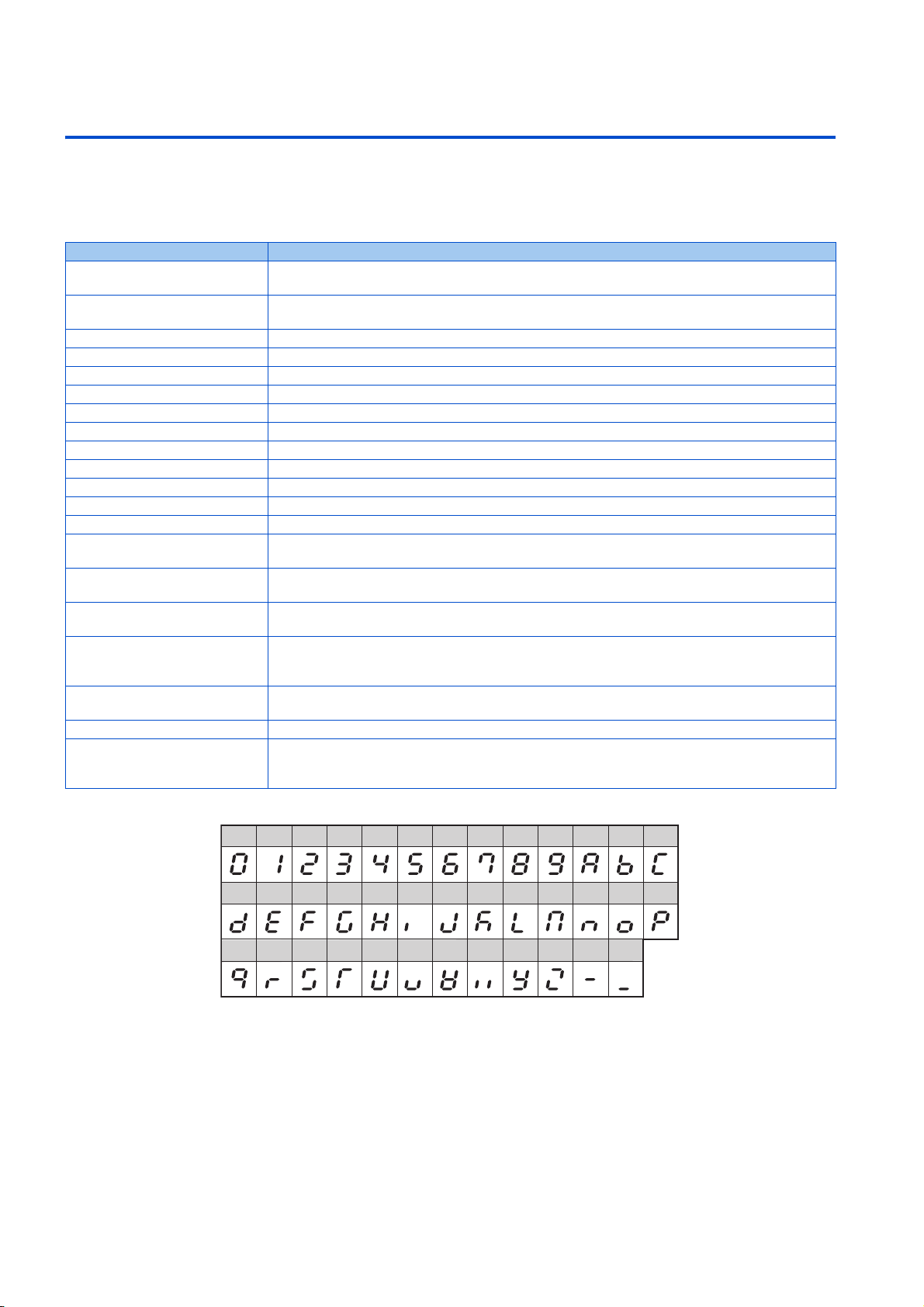
Digital characters and their corresponding printed equivalents
0123456789ABC
DEFGH I J KLMNOP
QRSTUVWXYZ - _
Trademarks
• Ethernet is a registered trademark of Fuji Xerox Corporation in Japan.
• MODBUS is a registered trademark of SCHNEIDER ELECTRIC USA, INC.
• BACnet is a registered trademark of the American Society of Heating, Refrigerating and Air-Conditioning Engineers
(ASHRAE).
• DeviceNet and EtherNet/IP are registered trademarks of ODVA (Open DeviceNet Vendor Association, INC).
• PROFIBUS and PROFINET are either trademarks or registered trademarks of PROFIBUS & PROFINET International.
• CC-Link IE TSN and CC-Link IE Field Network Basic are registered trademarks of CC-Link Partner Association.
• Other company and product names herein are the trademarks and registered trademarks of their respective owners.
1. Introduction
6
Page 8

Notes on descriptions in this Instruction Manual
• Connection diagrams in this Instruction Manual appear with the control logic of the input terminals as sink logic, unless
otherwise specified. (Refer to the FR-E800 Instruction Manual (Connection) for the switching of the control logic of the
inverter.)
1
2
Precautions
• Some of the communication protocols and the plug-in options cannot be used together as shown in the following table. For
the application and protocol settings, refer to page 173.
CC-Link IE TSN
BACnet/IP
CC-Link IE Field Network Basic
CC-Link IE TSN — × × × ×
CC-Link IE Field Network Basic × — ×
BACnet/IP — ×
EtherNet/IP × — ×
PROFINET × × × —
CC-Link (when the FR-A8NC E kit is installed) × × — × ×
PROFIBUS-DP (when the FR-A8NP E kit is
installed)
DeviceNet (when the FR-A8ND E kit is installed) × × —
EtherNet/IP
PROFINET
CC-Link (when the FR-A8NC E kit is installed)
×—×
DeviceNet (when the FR-A8ND E kit is installed)
PROFIBUS-DP (when the FR-A8NP E kit is installed)
3
4
5
6
7
8
9
10
NOTE
• FR Configurator2 can be used for any communication protocol or plug-in option.
1. Introduction
7
Page 9
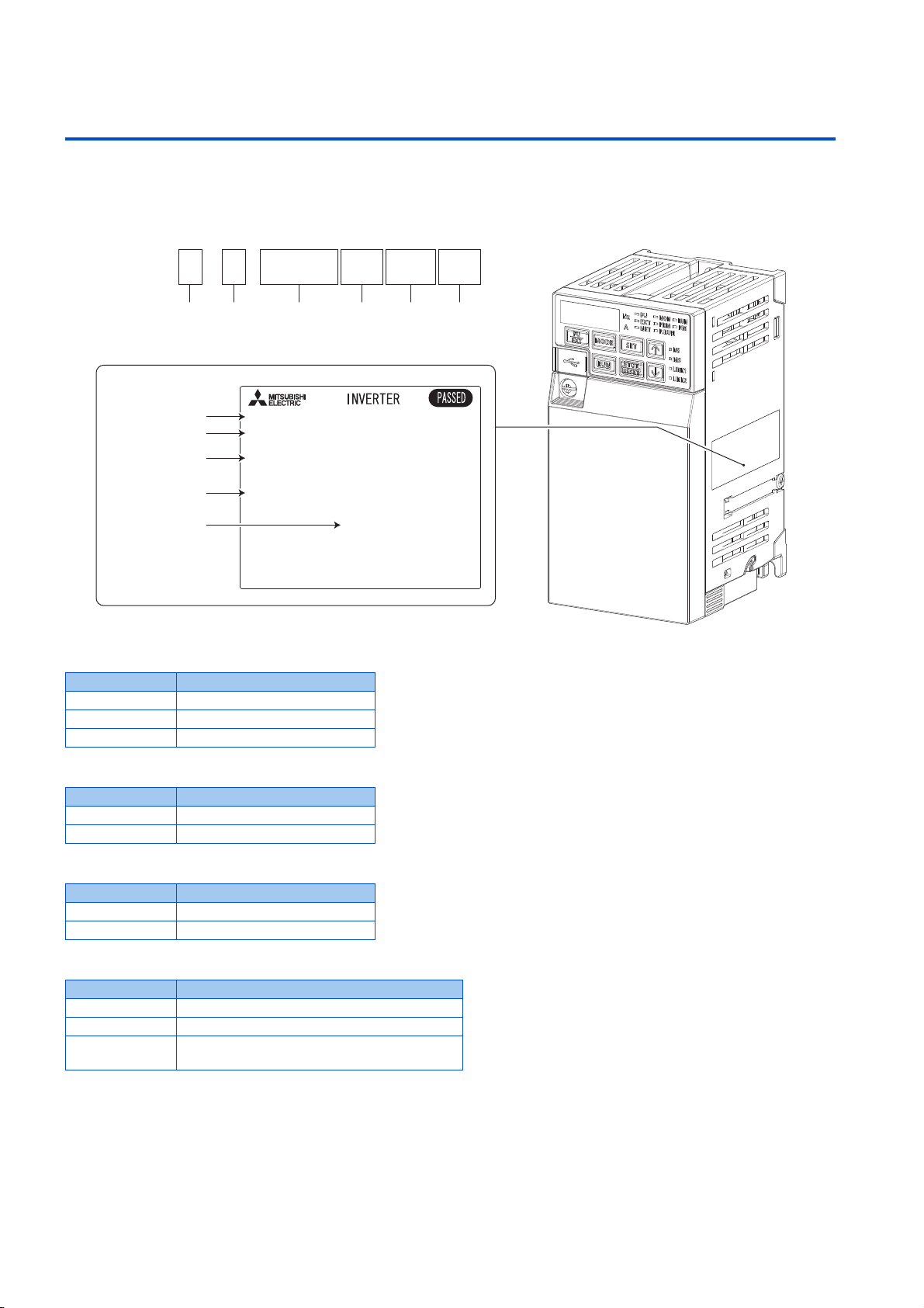
1.1 Product checking
FR-E8 0 -
A B C D E F
00082EPA
Rating plate
Input rating
Output rating
SERIAL
Inverter model
INPUT :XXXXX
MODEL :FR-E820-0008EPA
OUTPUT:XXXXX
SERIAL:XXXXXXXXXXX
MADE IN XXXXX
Country of origin
Inverter model
• A: The voltage class is shown.
Symbol Voltage class
2 200 V class
4 400 V class
6 575 V class
• B: The number of phases of the power source is shown.
Symbol Description
None Three-phase input
S Single-phase input
• C: The inverter rated capacity or the inverter rated current is shown.
Symbol Description
0.1K to 22K Inverter ND rated capacity (kW)
0008 to 0900 Inverter ND rated current (A)
• D: The communication type and the functional safety specification are shown.
Symbol Communication / functional safety
None Standard model (RS-485 + SIL2/PLd)
E Ethernet model (Ethernet + SIL2/PLd)
SCE
Safety communication model (Ethernet + SIL3/
PLe)
1. Introduction
8
1.1 Product checking
Page 10
• E: The output specification for monitoring and the rated frequency are shown for the standard model, and the
NOTE
Rating plate example
Symbol Year Month Control number
SERIAL
communication protocol group is shown for the Ethernet model and the safety communication model. The control logic is
fixed to the source logic for the safety communication model.
1
Rated
Symbol Monitoring/protocol specifications
-1 Pulse (terminal FM) 60 Hz Sink logic
-4 Voltage (terminal AM) 50 Hz Source logic
-5 Voltage (terminal AM) 60 Hz Sink logic
PA
PB
• F: Availability of circuit board coating / plated conductors is shown.
None Without coating Without plated conductors
-60 With coating Without plated conductors
-06
Protocol group A (CC-Link IE TSN, CC-Link IE Field Network Basic,
MODBUS/TCP, EtherNet/IP, and BACnet/IP)
Protocol group B (CC-Link IE TSN, CC-Link IE Field Network Basic,
MODBUS/TCP, PROFINET)
*1 The initial status of the control logic differs depending on the inverter model.
Sink logic for the models indicated with the rated capacity (kW)
Source logic for the models indicated with the rated current (A).
Symbol Circuit board coating
*2
*1 Conforming to IEC 60721-3-3 3C2
*2 Applicable for the FR-E820-0470(11K) or higher, and the FR-E840-0230(11K) or higher.
With coating With plated conductors
• In this Instruction Manual, the inverter model name consists of the applicable motor capacity and the rated current.
(Example) FR-E820-0008(0.1K)
*1
frequency
(initial setting)
60 Hz Sink logic
50 Hz
Plated conductor
Input signal
(initial status)
Sink logic / source
*1
logic
Control logic
Safety stop
Source logic
(fixed)
signal
2
3
4
5
6
7
8
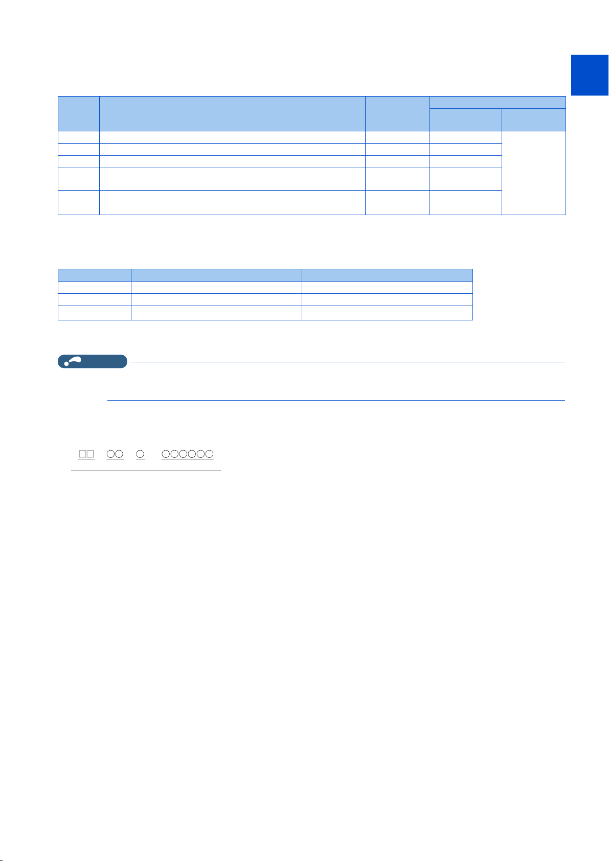
How to read the SERIAL number
The SERIAL consists of two symbols, three characters indicating the production
year and month, and six characters indicating the control number.
The last two digits of the production year are indicated as the Year, and the Month
is indicated by 1 to 9, X (October), Y (November), or Z (December).
9
10
1. Introduction
1.1 Product checking
9
Page 11

1.2 Related manuals
Manuals related to the FR-E800 inverter are shown in the following table.
Name Manual number
FR-E800 Inverter Safety Guideline IB-0600857ENG
FR-E860 Inverter Safety Guideline IB-0600862ENG
FR-E800-E Inverter Safety Guideline IB-0600860ENG
FR-E860-E Inverter Safety Guideline IB-0600863ENG
FR-E800-SCE Inverter Safety Guideline IB-0600921ENG
FR-E860-SCE Inverter Safety Guideline IB-0600924ENG
FR-E800 Instruction Manual (Connection) IB-0600865ENG
FR-E860 Instruction Manual (Connection) IB-0600906ENG
FR-E800 Instruction Manual (Function) IB-0600868ENG
FR-E800 Instruction Manual (Maintenance) IB-0600874ENG
FR-E800 Instruction Manual (Functional Safety) BCN-A23488-000
FR-E800-SCE Instruction Manual (Functional safety) BCN-A23488-004
FR Configurator2 Instruction Manual IB-0600516ENG
PLC Function Programming Manual IB-0600492ENG
1. Introduction
10
1.2 Related manuals
Page 12

CHAPTER 2
CHAPTER 2
2.1 Outline ....................................................................................................................................................................12
2.2 Wiring......................................................................................................................................................................13
2.3 Ethernet cable connection ......................................................................................................................................15
2.4 Initial setting for Ethernet communication...............................................................................................................17
2.5 CC-Link IE TSN ......................................................................................................................................................18
2.6 CC-Link IE Field Network Basic..............................................................................................................................52
2.7 MODBUS/TCP........................................................................................................................................................81
2.8 BACnet/IP ...............................................................................................................................................................97
2.9 MELSOFT / FA product connection......................................................................................................................110
2.10 SLMP ....................................................................................................................................................................113
2.11 EtherNet/IP ...........................................................................................................................................................128
2.12 PROFINET............................................................................................................................................................149
2.13 Backup/restore......................................................................................................................................................167
2.14 Inverter-to-inverter link function ............................................................................................................................169
2.15 Ethernet communication parameters ....................................................................................................................172
Ethernet Communication
4
5
6
7
8
9
10
11
Page 13

2 Ethernet Communication
2.1 Outline
Ethernet communication is available for the Ethernet model and the safety communication model.
Precautions for communication
• To maintain the security (confidentiality, integrity, and availability) of the inverter and the system against unauthorized
access, DoS*1attacks, computer viruses, and other cyberattacks from external devices via network, take appropriate
measures such as firewalls, virtual private networks (VPNs), and antivirus solutions. We shall have no responsibility or
liability for any problems involving inverter trouble and system trouble by DoS attacks, unauthorized access, computer
viruses, and other cyberattacks.
• Depending on the network environment, the inverter may not operate as intended due to delays or disconnection in
communication. Carefully consider what type of environment the inverter will be used in and any safety issues related to
its use.
*1 DoS: A denial-of-service (DoS) attack disrupts services by overloading systems or exploiting vulnerabilities, resulting in a denial-of-service (DoS)
state.
Ethernet communication specifications
The communication specification varies depending on the specification of the master or the communication protocol.
Item Description
Category 100BASE-TX/10BASE-T
Data transmission speed 100 Mbps (100BASE-TX) / 10 Mbps (10BASE-T)
Transmission method Baseband
Maximum segment length 100 m between the hub and the inverter
Number of cascade connection stages Up to 2 (100BASE-TX) / up to 4 (10BASE-T)
Topology Line, star, or a combination of line and star
Interface RJ-45
Number of interfaces available 2
IP version IPv4
Operation status LEDs
LED name Description LED status Remarks
NS Communication status
MS Inverter status
LINK1
LINK2
NET
Connector for communication
(PORT1) status
Connector for communication
(PORT2) status
SLMP command request message
reception status
OFF Duplicate IP address not detected
Red Duplicate IP address detected
OFF Power-OFF / during inverter reset
Green Operating properly
Red Fault detected
OFF Power-OFF/link-down
Blinking green Link-up (Data reception in progress)
Solid green Link-up
OFF Power-OFF/link-down
Blinking green Link-up (Data reception in progress)
Solid green Link-up
OFF
Blinking green
Solid green Network operation mode
Power-OFF / inverter identification disabled /
inverter identification paused
Inverter identification in progress
*1
*1 While "1 (initial value)" is set in Pr.1399 Inverter identification enable/disable selection, this LED blinks when the MAC/IP address of the
2. Ethernet Communication
12
2.1 Outline
inverter match to the MAC/IP address specified by using engineering software such as FR Configurator2.
Page 14
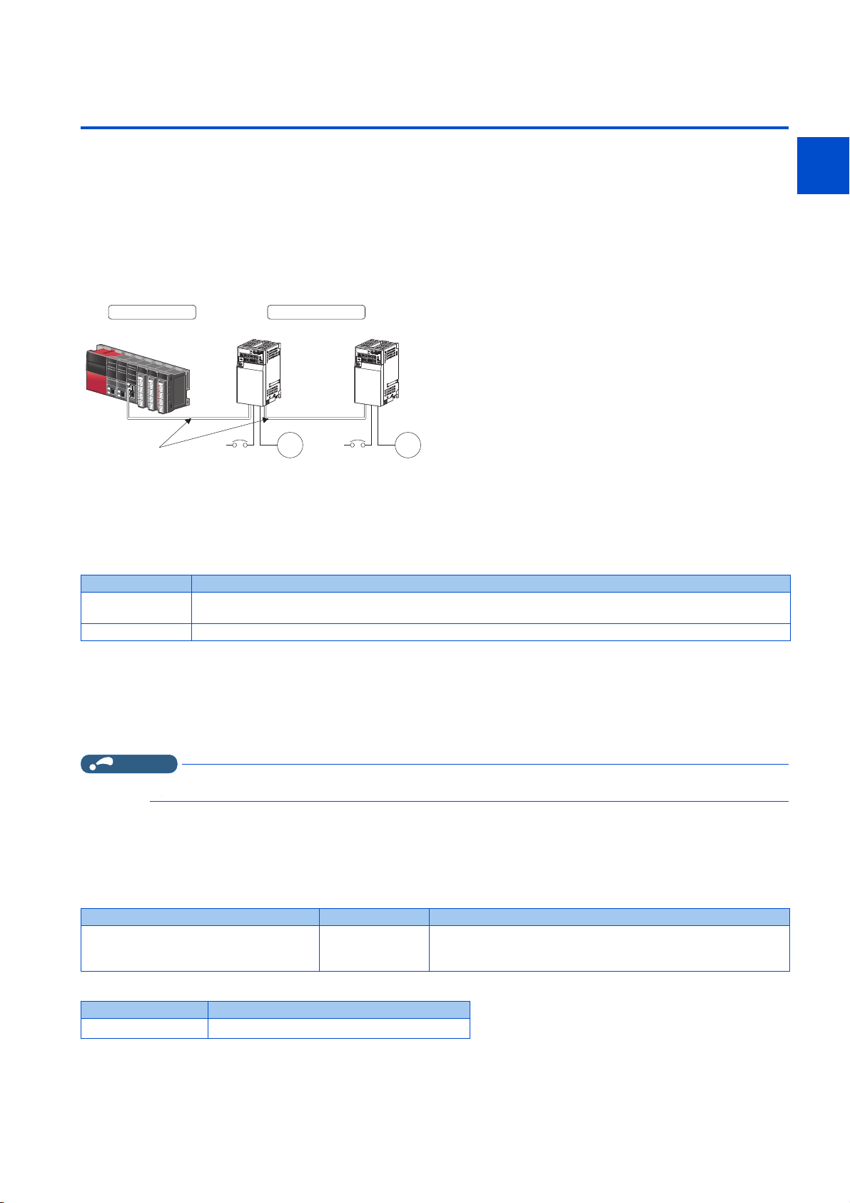
2.2 Wiring
Inverter
Motor
Power
supply
Inverter
Motor
Power
supply
Slave station
Ethernet cable
Master station
1
2.2.1 System configuration example
1. Select the connection method. (Refer to page 13.)
2. Prepare the equipment required for wiring. (Refer to page 13.)
3. Turn OFF the power of the programmable controller and the inverter.
4. Connect the master station and the inverters with Ethernet cables. (Refer to page 15.)
2.2.2 Network configuration
Network topology
The network can be wired into star topology or line topology. A network can consist of a combination of star and line topologies.
2
3
4
5
6
7
8
Item Description
Star topology
Line topology Modules are configured into a line with Ethernet cables. A switching hub is not required.
Modules are configured into a star using a switching hub and Ethernet cables. Slave stations can be easily added in a
star topology. Furthermore, data link continues among normally-operating stations in a star topology.
Station number and connection position
Modules can be connected in any order regardless of the station number.
Replacing CC-Link IE TSN devices
For star topology, slave stations can be replaced without powering off the whole system.
NOTE
• Refer to the Master Module User's Manual for detailed network configurations.
2.2.3 Network components
Connection cable
Use Ethernet cables compliant with the following standards.
Ethernet cable Connector Type
Category 5 or higher straight cable (double
shielded / STP)
• Recommended product (as of April 2019)
RJ-45 connector
The following conditioning cables:
• IEEE 802.3 (100BASE-TX)
• ANSI/TIA/EIA-568-B (Category 5)
9
10
Model Manufacturer
SC-E5EW series
*1 SC-E5EW cable is for in-enclosure and indoor uses. SC-E5EW-L cable is for outdoor use.
*1
Mitsubishi Electric System & Service Co., Ltd.
2. Ethernet Communication
2.2 Wiring
13
Page 15

NOTE
• Depending on the cable connector shape, the cable may not be connected to the inverter.
Hubs
Use hubs that meet the following conditions. Operation is not guaranteed if the hubs do not meet these conditions.
• Compliance with the IEEE 802.3 (100BASE-TX)
• Support of the auto MDI/MDI-X function
• Support of the auto-negotiation function
• Switching hub (layer 2 switch)
*1 A repeater hub is not available.
Industrial switching hub
Model Manufacturer
NZ2EHG-T8N Mitsubishi Electric Corporation
NZ2EHG-T8 (discontinued product) Mitsubishi Electric Corporation
DT135TX Mitsubishi Electric System & Service Co., Ltd.
*1
2. Ethernet Communication
14
2.2 Wiring
Page 16

2.3 Ethernet cable connection
This section explains Ethernet cable connection and the relevant precautions. For the details of the network configuration and
the cables and hubs used for wiring, refer to page 13 onwards.
1
2
2.3.1 Wiring method
Reinstallation
1. Turn OFF the power of the programmable controller and the inverter.
2. Remove the inverter front cover.
3. Check the orientation of the connectors. Insert the connector part of the Ethernet cable to the communication
connector until it clicks.
Disconnection
1. Turn OFF the power of the programmable controller and the inverter.
3
4
5
6
7
8
9
10
2. Remove the inverter front cover.
3. Hold down the latch on the Ethernet cable connector, and pull out the cable while holding the latch.
NOTE
• There is no need to distinguish between PORT1 and PORT2 on the inverter (except for PROFINET).
• When only one connector is used in star topology, either PORT1 or PORT2 is applicable. (Use PORT1 for PROFINET.)
• When using two connectors for line topology, an Ethernet cable can be connected to the connectors in any combination. For
example, the cable can be connected across two of PORT1 or across PORT1 and PORT2. (For PROFINET, use PORT1
for connection with the master, and use PORT2 for connection with PORT1 of the adjacent inverter.)
2. Ethernet Communication
2.3 Ethernet cable connection
15
Page 17
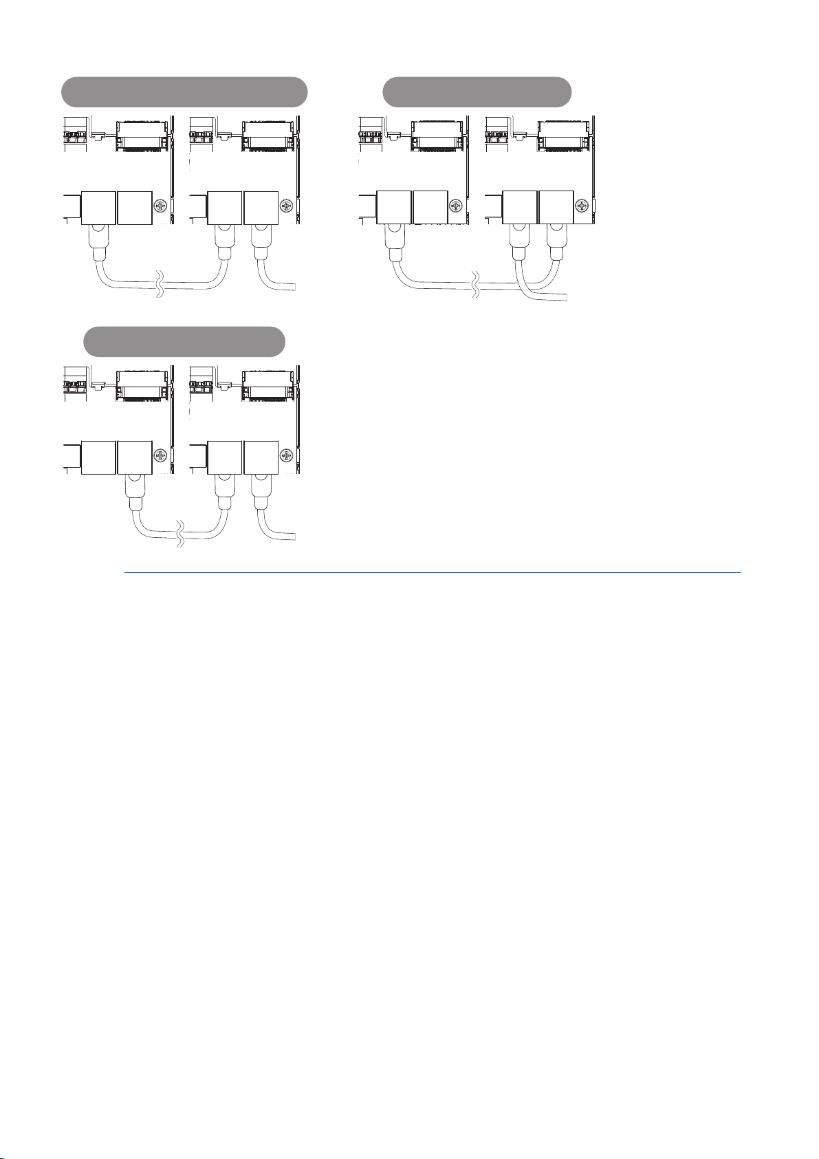
2.3.2 Wiring precautions
Connection between
PORT1 and PORT1, PORT2 and PORT2
Connection between
PORT1 and PORT2
Connector
for
communication
(PORT2)
Connector
for
communication
(PORT1)
Connector
for
communication
(PORT2)
Connector
for
communication
(PORT1)
Connector
for
communication
(PORT2)
Connector
for
communication
(PORT1)
Connector
for
communication
(PORT2)
Connector
for
communication
(PORT1)
Connector
for
communication
(PORT2)
Connector
for
communication
(PORT1)
Connector
for
communication
(PORT2)
Connector
for
communication
(PORT1)
To the next
connector for
communication
(PORT2)
To the next
connector for
communication
(PORT2)
Connection between
PORT2 and PORT1 (PROFINET)
To the next
connector for
communication
(PORT1)
This section explains Ethernet cable connection and the relevant precautions.
Handling of the Ethernet cable
• Do not touch the conductors of the cable or the connector on the inverter. Keep the conductors free of dust or dirt. If oil
from your hand, dirt or dust is attached to the core, it can increase transmission loss, arising a problem in data link.
• Check the following:
Is any Ethernet cable disconnected?
Is any of the Ethernet cables shorted?
Are the connectors securely connected?
• Do not use Ethernet cables with broken latches. Doing so may cause the cable to unplug or malfunction.
• The maximum station-to-station distance is 100 m. However, the distance may be shorter depending on the operating
environment of the cable. For details of the cable, contact your cable manufacturer.
Connecting and disconnecting of the Ethernet cable
Hold the connector part when connecting and disconnecting the Ethernet cable. Pulling a cable connected to the inverter may
damage the inverter or cable, or result in malfunction due to poor contact.
Network configuration
Check the network configuration before wiring, and perform correct wiring. For example, using ring topology may cause system
failure.
16
2. Ethernet Communication
2.3 Ethernet cable connection
Page 18

2.4 Initial setting for Ethernet communication
* * * . * * * . * * * . * * *
Set the value in the first octet in Pr.1434.
Set the value in the second octet in Pr.1435.
Set the value in the third octet in Pr.1436.
Set the value in the fourth octet in Pr.1437.
Use the following parameters to perform required settings for Ethernet communication between the inverter and other devices.
To make communication between other devices and the inverter, perform the initial settings of the inverter parameters to match
the communication specifications of the devices. Data communication cannot be made if the initial settings are not made or if
there is any setting error.
Pr. Name
1434
N600
1435
N601
1436
N602
1437
N603
IP address 1 (Ethernet) 192
*1
IP address 2 (Ethernet) 168
*1
IP address 3 (Ethernet) 50
*1
IP address 4 (Ethernet) 1
*1
*1 The setting is applied after an inverter reset or next power-ON.
Initial
value
IP address (Pr.1434 to Pr.1437)
Enter the IP address of the inverter to be connected to Ethernet in Pr.1434 to Pr.1437. (Enter the IP address assigned by the
network administrator.)
Setting
range
0 to 255 Enter the IP address of the inverter to be connected to Ethernet.
Description
1
2
3
4
5
6
7
8
9
10
2. Ethernet Communication
2.4 Initial setting for Ethernet communication
17
Page 19

2.5 CC-Link IE TSN
NOTE
2.5.1 Outline
Data can be transmitted to IT systems while performing real-time cyclic communication control.
Some functions are not supported depending on the date of manufacture of the inverter. For details of specification changes,
refer to page 220.
CC-Link IE TSN authentication classes
• Devices (nodes) and switches on the CC-Link IE TSN network are classified into different authentication classes according
to their functionality and performance. There are two authentication classes: A and B. For details of the authentication class
of each product, check the information on the web site of the CC-Link Partner Association, or refer to catalogs and manuals
of each product. Different functions and system configurations are available depending on the authentication class of the
devices to be used. For example, use authentication class B devices to construct a high-speed motion control system. For
details of system construction such as mixing devices of both class A and class B, check the manuals of the applicable
master device.
Communication specifications
The communication specification varies depending on the specification of the master.
Item Description
Transmission speed 100 Mbps (10 Mbps is not supported.)
Minimum synchronization cycle 5000.00 μs
Authentication class Authentication class A
Communication method Time sharing method
Synchronization function Conforms to IEEE 1588v2
Maximum number of connected units 121 units (sum of master and slave stations)
Maximum number of branches No upper limit on the same Ethernet network
Connection cable
Topology
Node type Slave station
RX 32 bits
Maximum cyclic size (of
one node)
*1 Ring topology will be supported later.
• To use the CC-Link IE TSN, do not install the FR-A8NC to the inverter. (Installing the FR-A8NC E kit disables CC-Link IE TSN.)
RY 32 bits
RWr 32 words
RWw 32 words
Ethernet cable (IEEE 802.3 100BASE-TX compliant cable or ANSI/TIA/EIA-568-B (Category 5)
compliant shielded 4-pair branched cable)
Line, star, or a combination of line and star
*1
2. Ethernet Communication
18
2.5 CC-Link IE TSN
Page 20
Operation status LEDs
RJ71GN11-T2
Communication speed 100 Mbps
FR-E800 (authentication class A)
Communication speed 100 Mbps
120 units maximum
LED name Description LED status Remarks
OFF Power-OFF
Blinking green Data transmission not performed
NS Communication status
MS Inverter status
LINK1 Connector for communication (PORT1) status
LINK2 Connector for communication (PORT2) status
Solid green Data transmission in progress
Blinking red Communication interrupted
Solid red Duplicate IP address detected
OFF Power-OFF / during inverter reset
Green Operating properly
Red Fault detected
OFF Power-OFF/link-down
Blinking green Link-up (Data reception in progress)
Solid green Link-up
OFF Power-OFF/link-down
Blinking green Link-up (Data reception in progress)
Solid green Link-up
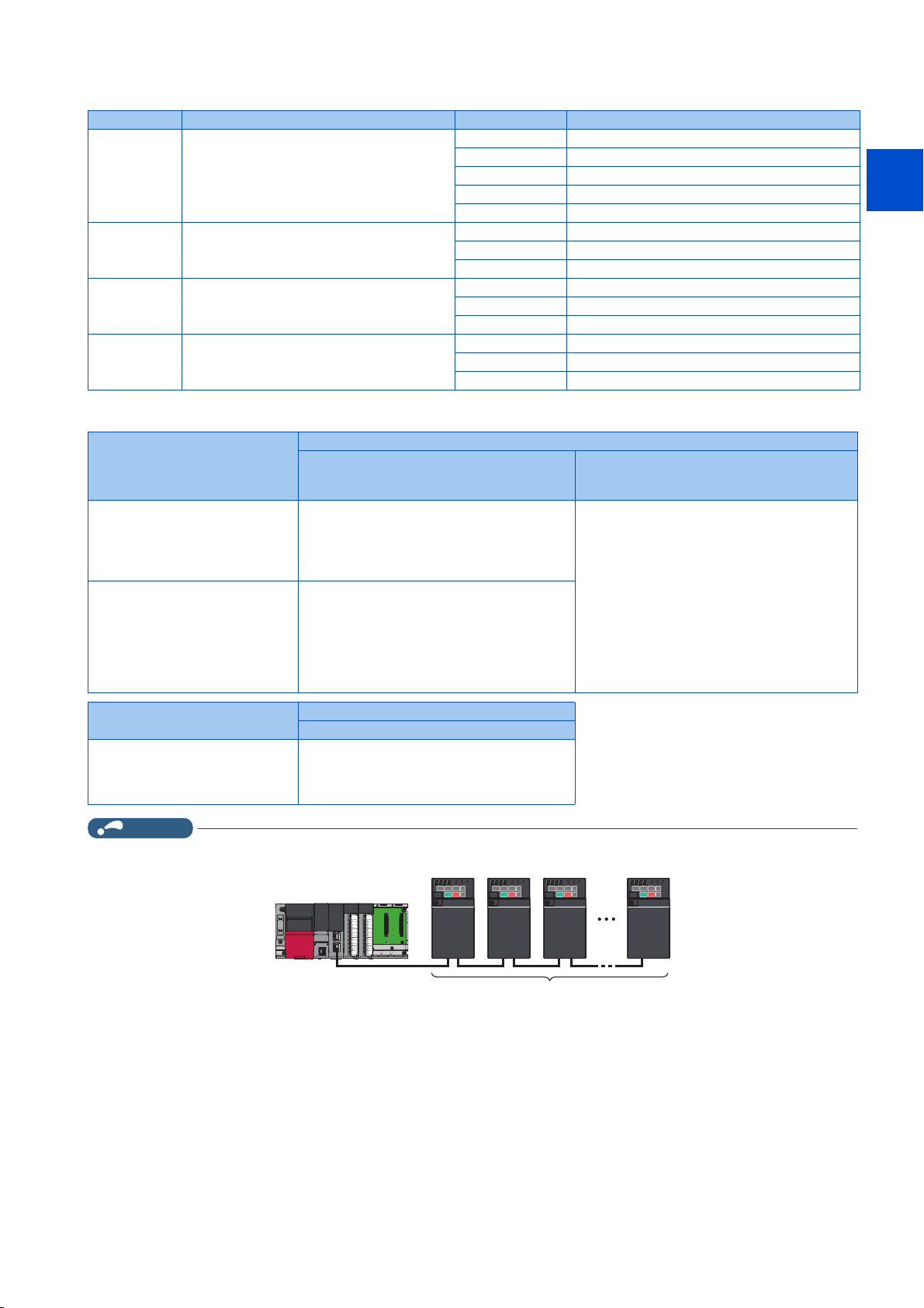
Network configuration
1
2
3
4
5
Master station
MELSEC iQ-R series master/local
module RJ71GN11-T2 or a master
station that supports both 1 Gbps
and 100 Mbps communication
speeds
MELSEC iQ-F series master/local
module FX5-CCLGN-MS or a master
station that supports 1 Gbps
communication speed only
Master station
MELSEC iQ-R series Motion module
RD78G[]/GH[]
NOTE
• When all slave stations are authentication class A products, up to 120 units can be connected.
Slave station
FR-E800 (authentication class A) only
Line topology, star topology, or a combination of
line and star
Set 100 Mbps for the communication speed of the
master station.
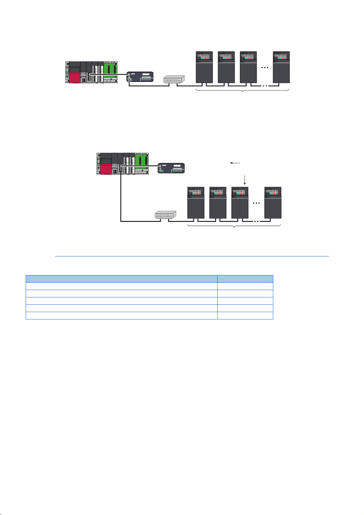
Star topology or a combination of line and star
(Line topology only is not supported.)
Connection sequence: Master station →
General-purpose switching hub → FR-E800
(authentication class A)
Line topology is available for connection starting
from the FR-E800.
Slave station
FR-E800 (authentication class A) only
Connection sequence: Master station → FRE800 (authentication class A)
Line topology is available for connection starting
from the FR-E800.
Mixture of FR-E800 (authentication class A)
and FR-A800-GN or other device
(authentication class B)
Star topology or a combination of line and star
(Line topology only is not supported.)
Connection sequence: Master station → Slave
station (authentication class B) → Generalpurpose switching hub → FR-E800 (authentication
class A)
Line topology is available for connection starting
from the FR-E800.
6
7
8
9
10
2. Ethernet Communication
2.5 CC-Link IE TSN
19
Page 21
• When both authentication class B and class A products are used, the data size of all class A units must not exceed 2k bytes
RJ71GN11-T2
Communication
speed 1 Gbps
FR-E800 (authentication class A)
Communication speed 100 Mbps
10 units maximum
Remote I/O
(authentication
class B)
Communication
speed 1 Gbps
General-purpose
switching hub
FR-E800 (authentication class A)
Communication speed 100 Mbps
Remote I/O
(authentication
class B)
Communication
speed 1 Gbps
General-purpose
switching hub
Port 1
Port 2
Total number of
slave stations:
120 units maximum
RJ71GN11-T2
(firmware version
"12" or later)
Communication
speed 1 Gbps
for cyclic transmission. Up to 10 authentication class A units can be connected per port on the master station.
• When the master station has more than one port, use separate ports for both authentication classes to enable connection of
up to 120 slave station units. For example, use port 1 for authentication class B products only, and port 2 for class A products
only.
• For details of network configurations, refer to the Master Module User's Manual.
Related manuals
Name Manual number
MELSEC iQ-R CC-Link IE TSN User's Manual (Startup) SH-082127ENG
MELSEC iQ-R CC-Link IE TSN User's Manual (Application) SH-082129ENG
MELSEC iQ-F FX5 User's Manual (CC-Link IE TSN) SH-082215ENG
MELSEC iQ-R Motion Module User's Manual (Startup) IB-0300406ENG
MELSEC iQ-R Motion Module User's Manual (Application) IB-0300411ENG
2.5.2 CC-Link IE TSN configuration
Procedure
The following shows the procedure to connect the inverter with a Mitsubishi Electric master device.
Before communication
1. Connect each unit with an Ethernet cable. (Refer to page 15.)
2. Enter the IP address (Pr.1434 to Pr.1437). (Refer to page 17.)
3. Set "45238" (CC-Link IE TSN) in any of Pr.1427 to Pr.1430 Ethernet function selection 1 to 4. (Refer to page 26.)
In the initial status, Pr.1429 = "45238" (CC-Link IE TSN) and setting is not required.
Registering a profile
2. Ethernet Communication
20
2.5 CC-Link IE TSN
4. Reset the inverter, or turn OFF and then ON the power.
1. Start the engineering software (GX Works3).
2. On the menu bar, select [Tool] > [Profile Management] > [Register...].
3. Select a CSP+ file to be registered on the "Register Profile" screen, and click the [Register] button.
Page 22
NOTE
• A profile is a compressed file (such as *.zip, *.ipar, and *.cspp). Register a profile without decompressing the file.
• Profile registration is not required for the next time onwards.
1
Creating a project file
1. For information on creating and opening a project, go to [Help] > [GX Works3 Help].
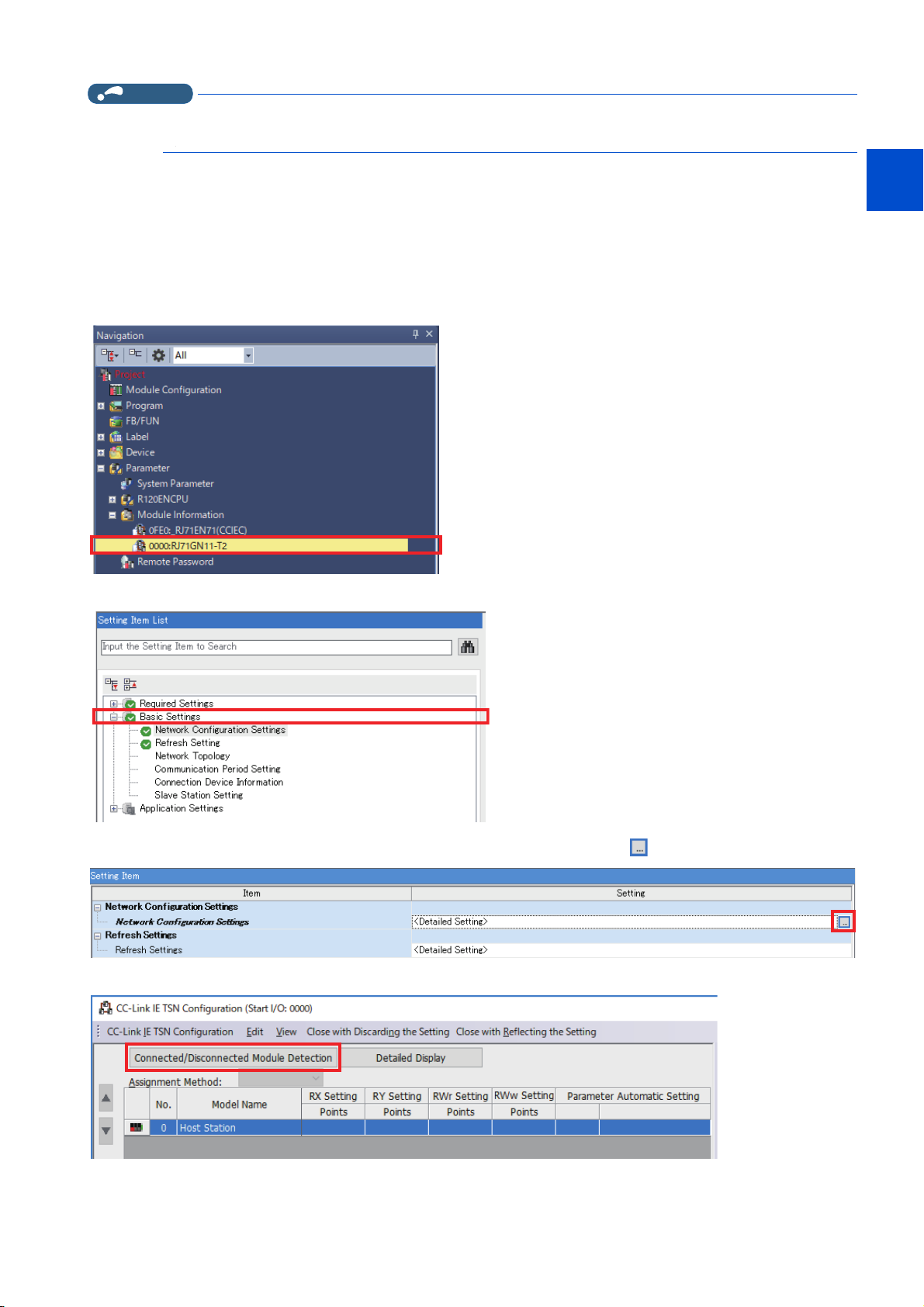
Detecting an Inverter
Detection is not possible when the data link is not established with the master module. For details, refer to the Master Module
User's Manual.
1. In the "Navigation" window, select [Parameter] > [Module Information] then select the module name.
2. Select [Basic Settings] in the "Setting Item List" window.
2
3
4
5
6
7
8
3. In the "Setting Item" window, go to [Network Configuration Settings] then click next to the [Detailed Setting] field.
4. Click [Connected/Disconnected Module Detection] in the "CC-Link IE TSN configuration" window.
9
10
2. Ethernet Communication
2.5 CC-Link IE TSN
21
Page 23
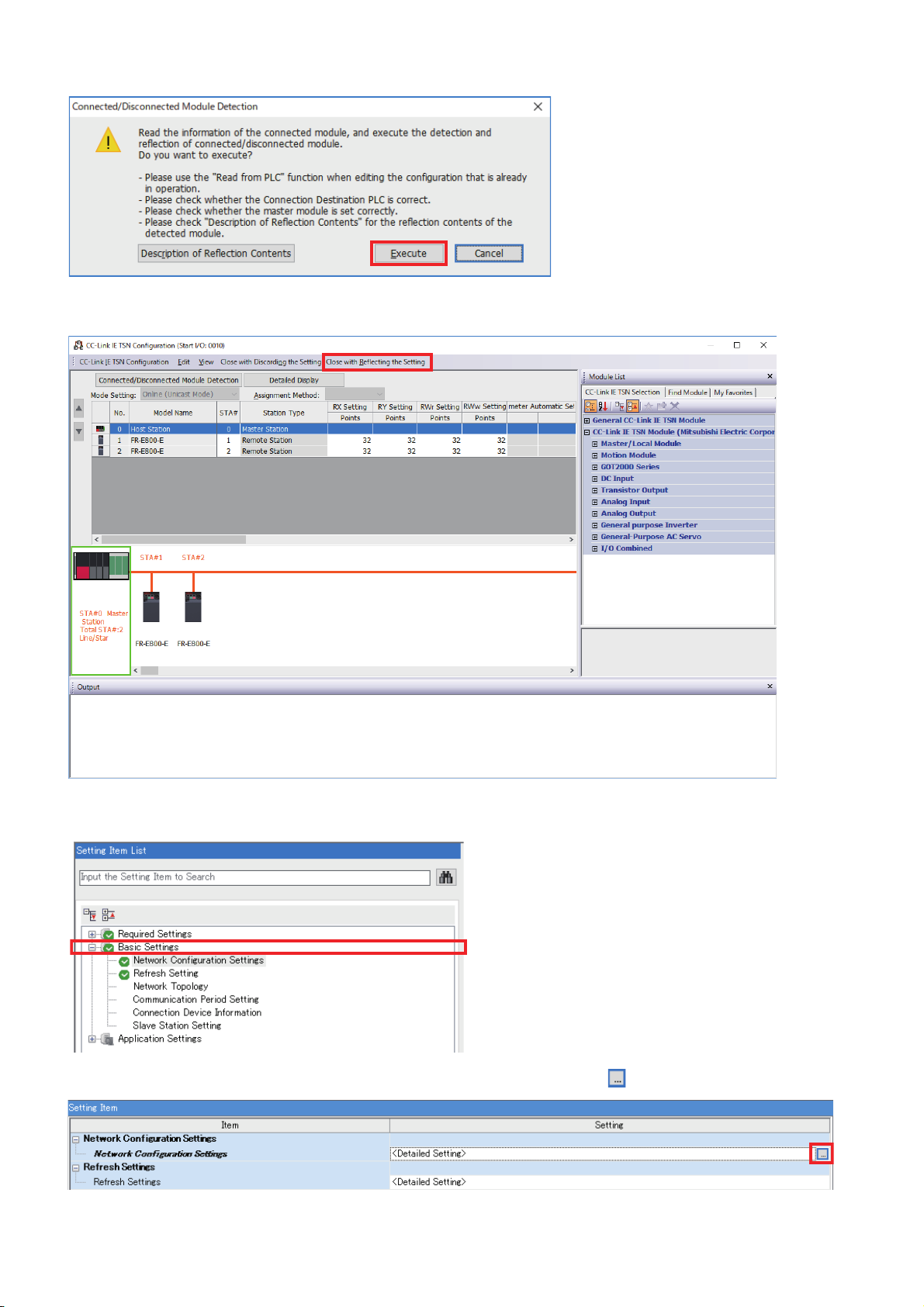
5. Read the cautions in the "Connected/Disconnected Module Detection" window and click [Execute].
HostStation
6. The FR-E800-E or the FR-E800-SCE will appear on the screen when it is detected. (FR-E800-E inverters are
displayed in the following example.) Click [Close with Reflecting the Setting] to close the window.
System setting window (communication speed setting of the master: 1 Gbps)
1. Select [Basic Settings] in the "Setting Item List" window.
2. In the "Setting Item" window, go to [Network Configuration Settings] then click next to the [Detailed Setting] field.
2. Ethernet Communication
22
2.5 CC-Link IE TSN
Page 24
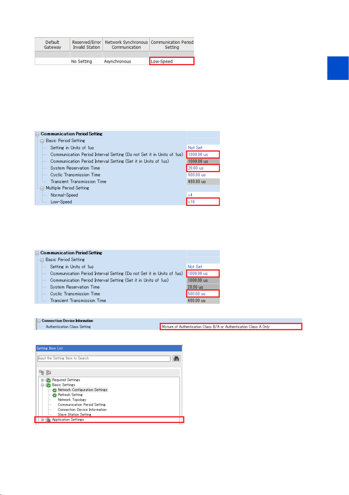
3.
In the "CC-Link IE TSN Configuration" window, set "Low-Speed" for [Communication Period Setting].
4. Set "1000.00 μs" (initial value) for [Communication Period Interval Setting (Do not Set it in Units of 1us)].
• When RJ71GN11-T2 is the master
Set "20.00 μs" (initial value) for [System Reservation Time].
Consider the scaling factor in [Multiple Period Setting] - [Low-Speed] to change the settings for [Basic Period Setting]. Refer to
the following examples.
[Communication Period Interval Setting] = "5000.00 μs" / "16 (initial value)" (minimum value)
[System Reservation Time] = "200.00 μs" / "16 (initial value)" (minimum value)
1
2
3
4
5
6
7
• When FX5-CCLGN-MS is the master
Set "500.00 μs" (initial value) for [Cyclic Transmission Time].
Consider the scaling factor in [Multiple Period Setting] - [Low-Speed] to change the settings for [Basic Period Setting]. Refer to
the following example.
[Communication Period Interval Setting] = "5000.00 μs" / "16 (fixed)" (minimum value)
5. Set "Mixture of Authentication Class B/A or Authentication Class A Only" for [Authentication Class Setting].
6. Select [Application Settings] in the "Setting Item List" window.
8
9
10
2. Ethernet Communication
2.5 CC-Link IE TSN
23
Page 25
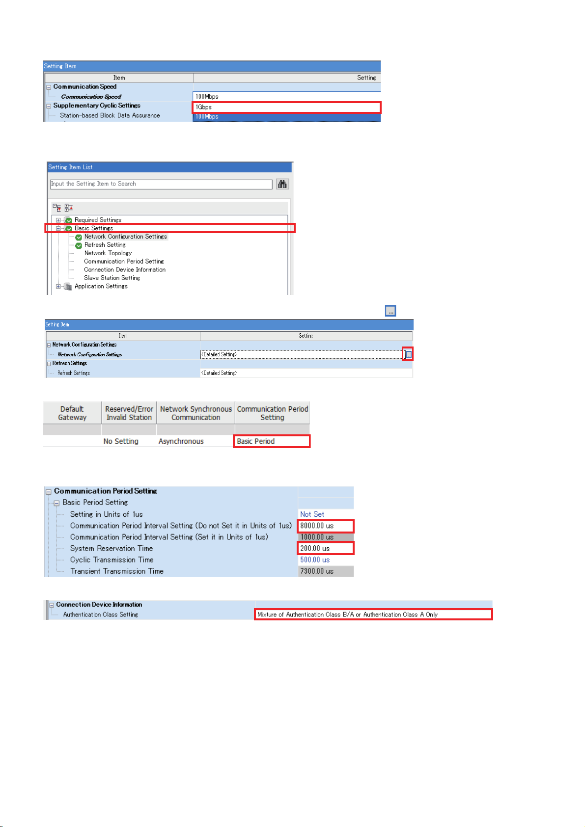
7. Set "1 Gbps" for [Communication Speed].
System setting window (communication speed setting of the master: 100 Mbps)
1. Select [Basic Settings] in the "Setting Item List" window.
2. In the "Setting Item" window, go to [Network Configuration Settings] then click next to the [Detailed Setting] field.
3. In the "CC-Link IE TSN Configuration" window, set "Basic Period" for [Communication Period Setting].
4. Set "5000.00 μs" or larger value for [Communication Period Interval Setting (Do not Set it in Units of 1us)].
Set "200.00 μs" for [System Reservation Time].
5. Set "Mixture of Authentication Class B/A or Authentication Class A Only" for [Authentication Class Setting].
2. Ethernet Communication
24
2.5 CC-Link IE TSN
Page 26
6.
XXX.XXX.XXX.XXX
XX-XX-XX-XX-XX-XX
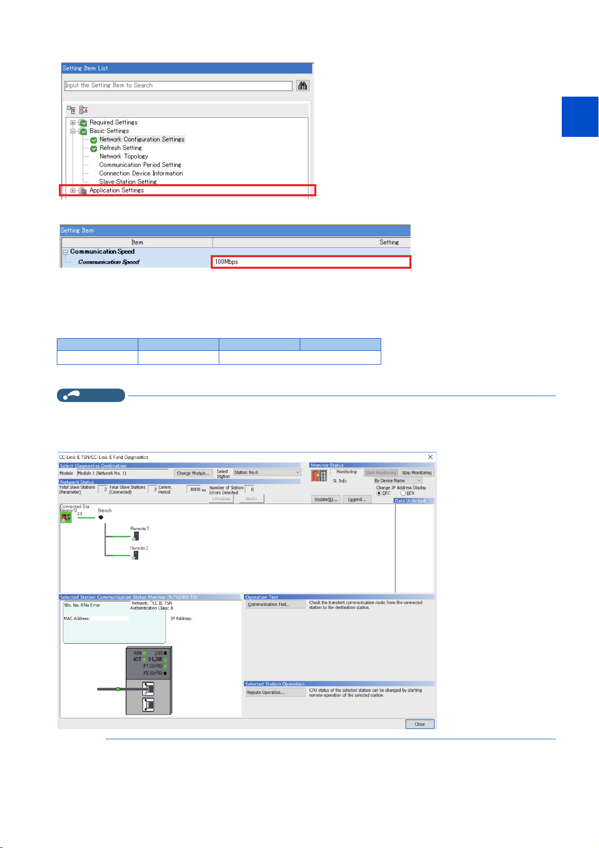
Select [Application Settings] in the "Setting Item List" window.
7. Set "100 Mbps" for [Communication Speed].
1
2
3
4
5
Checking communication
The following table shows the status of the LEDs when the programmable controller and the inverter are connected
successfully. Check the [CC Link IE TSN / CC Link IE Field Diagnostics] window to confirm that the communication is
established between them.
NS MS LINK1 LINK2
Solid green Solid green
*1 The LED on either LINK1 or LINK2 will blink depending on the port (port 1 or 2) the Ethernet cable is connected to.
NOTE
• If the FR-E800-(SC)E cannot be detected, on the menu bar select [Diagnostics (D)] → [CC Link IE TSN / CC Link IE Field
Diagnostics]. The "CC Link IE TSN / CC Link IE Field Diagnostics" window will be displayed. Broken or disconnected wires
can be detected.
• The network configuration diagram is displayed in star topology even if the devices are connected in line topology.
Blinking green
*1
6
7
8
9
10
2. Ethernet Communication
2.5 CC-Link IE TSN
25
Page 27

2.5.3 Initial setting for CC-Link IE TSN
NOTE
Use the following parameters to perform required settings for Ethernet communication between the inverter and other devices.
To make communication between other devices and the inverter, perform the initial settings of the inverter parameters to match
the communication specifications of the devices. Data communication cannot be made if the initial settings are not made or if
there is any setting error.
Pr. Name
1427
N630
1428
N631
1429
N632
1430
N633
Ethernet function
*1
selection 1
Ethernet function
*1
selection 2
Ethernet function
*1
selection 3
Ethernet function
*1
selection 4
*1 The setting is applied after an inverter reset or next power-ON.
*2 The setting is available only for the FR-E800-EPA and the FR-E800-SCEPA.
*3 The setting is available only for the FR-E800-EPB and the FR-E800-SCEPB.
Initial
value
5001
45237
45238
9999
Setting range Description
502, 5000 to 5002, 5006
to 5008, 5010 to 5013,
9999, 34962
45237, 45238, 47808
61450
*3
, 44818*2,
Set the application, protocol, etc.
*2
,
Ethernet function selection (Pr.1427 to Pr.1430)
To select CC-Link IE TSN for the application, set "45238" (CC-Link IE TSN) in any of Pr.1427 to Pr.1430 Ethernet function
selection 1 to 4. In the initial status, Pr.1429 = "45238" (CC-Link IE TSN) and setting is not required.
• Change the setting if selected communication protocols cannot be used together. (Refer to page 7 and page 173.)
2. Ethernet Communication
26
2.5 CC-Link IE TSN
Page 28

2.5.4 Parameters related to CC-Link IE TSN
The following parameters are used for CC-Link IE TSN communication. Set the parameters as required.
Pr. Name Initial value Setting range Description
541
N100
544
*1
N103
1426
*1
N641
1442
*1
N660
1443
*1
N661
1444
*1
N662
1445
*1
N663
1446
*1
N664
1447
*1
N665
1448
*1
N666
1320 to
1329
N810 to
*1
N819
1330 to
1343
N850 to
*1
N863
804
D400
810
H700
Frequency command sign
selection
CC-Link extended setting 0
Link speed and duplex mode
selection
IP filter address 1 (Ethernet) 0
IP filter address 2 (Ethernet) 0
IP filter address 3 (Ethernet) 0
IP filter address 4 (Ethernet) 0
IP filter address 2 range
specification (Ethernet)
IP filter address 3 range
specification (Ethernet)
IP filter address 4 range
specification (Ethernet)
User Defined Cyclic
Communication Input 1 to 10
Mapping
User Defined Cyclic
Communication Output 1 to 14
Mapping
Torque command source
selection
Torque limit input method
selection
*1 The setting is applied after an inverter reset or next power-ON.
*2 The setting is available only for the FR-E800-EPB and the FR-E800-SCEPB.
0
0 0 to 4
9999
9999
9999
9999
9999
0 0, 1, 3 to 6
0 0 to 2 The torque limit input method can be selected.
0 Signed frequency command value
1 Unsigned frequency command value
0, 1, 12, 14, 18, 38,
100, 112, 114, 118,
138
0 to 255
0 to 255, 9999
*2
, 100*2, 12288 to
5
13787, 20488,
20489
9999 Function disabled
*2
, 101*2, 12288 to
6
13787, 16384 to
16483, 20488,
20489, 20981 to
20990
9999 Function disabled
Use this parameter to extend the function of the remote
registers for the CC-Link IE TSN.
Set the communication speed and the communication
mode (full-duplex/half-duplex).
Set the range of connectable IP addresses for the
network devices. (When Pr.1442 to Pr.1445 = "0 (initial
value)", the function is invalid.)
Set the index number for inverter parameters and
inverter control parameters. Functions can be assigned
to remote registers RWwn+4 to RWwn+17 when Pr.544
= "38".
Set the index number for inverter parameters, monitor
data, and inverter control parameters. Functions can be
assigned to remote registers RWrn+4 to RWrn+1F when
Pr.544 = "38".
In the torque control mode, the torque command source
can be selected.
1
2
3
4
5
6
7
8
9
10
Precautions for CC-Link IE TSN communication
• For CC-Link IE TSN, do not change initial values of Pr.1449 to Pr.1454 used to specify the Ethernet IP address range for
command source selection as the IP address is not used. Setting a value other than the initial value in any of the above
parameters may cause an Ethernet communication fault (E.EHR). If the fault occurs, reset the setting of the relevant
parameter to the initial value, or set "9999" in Pr.1432 Ethernet communication check time interval.
CC-Link extended setting (Pr.544)
• Use this parameter to select the function of the remote registers for the CC-Link IE TSN.
Pr.544 setting Description
0 (initial value), 1, 12, 14, 18 Compatible with the octuple setting of CC-Link Ver.2
38
100, 112, 114, 118 Compatible with the octuple setting of CC-Link Ver.2
138
*1 Refer to the PLC Function Programming Manual.
Compatible with the octuple setting of CC-Link Ver.2, user defined cyclic
communication data selected
Compatible with the octuple setting of CC-Link Ver.2,
user defined cyclic communication data selected
PLC function
*1
2. Ethernet Communication
2.5 CC-Link IE TSN
27
Page 29

Frequency command with sign (Pr.541)
NOTE
• The start command (forward/reverse rotation) can be inverted by adding a plus or minus sign to the value of the frequency
command sent through the CC-Link IE TSN.
•The Pr.541 Frequency command sign selection setting is applied to the frequency command from RWw1. (Refer to
page 35.)
Rotations per minute
(machine speed) setting
using Pr.37 and Pr.53
Disabled
Pr.541
setting
Sign Setting range Actual frequency command
0 Without 0 to 59000 0 to 590.00 Hz
1 With -32768 to 32767 (two's complement) -327.68 to 327.67 Hz
0 Without 0 to 65535 The rotation speed command or the machine
Enabled
1 With -32768 to 32767 (two's complement)
• Relationship between the start command and sign (Pr.541 = "1")
Start
command
Forward
rotation
Reverse
rotation
Sign of the frequency
command
Actual operation
command
+ Forward rotation
- Reverse rotation
+ Reverse rotation
- Forward rotation
• When Pr.541 = "1" (with sign)
• When EEPROM write is specified by turning ON of RYE, write mode error (error code H01) will occur.
• When both RYD and RYE are turned ON, RYD has precedence.
• When power is turned ON (inverter reset), the initial setting status of the sign bit is "positive" and the set frequency is 0 Hz.
(The motor does not operate at the frequency set before turning OFF the power (inverter reset).)
• When set frequency is written with the instruction code of HED or HEE, the sign of the frequency command is not changed.
speed command is selected depending on the
Pr.37 and Pr.53 settings. (1 increments)
I/O signal list
When Pr.544 = "0, 1, 12, 14, or 18"
• Remote I/O signals
Device No.
RYn0
RYn1
RYn2
RYn3
RYn4
RYn5
RYn6
RYn7
RYn8
RYn9
RYnA
RYnB
*7
Signal
Forward rotation command
Reverse rotation command
High-speed operation command
(terminal RH function)
*1
Middle-speed operation command
(terminal RM function)
*1
Low-speed operation command
(terminal RL function)
JOG operation selection 2
Second function selection
Current input selection
*1
*2
*2
*2
Pr.185 assignment function (NET X1)
Output stop (terminal MRS function)
Pr.186 assignment function (NET X2)
Pr.184 assignment function (RES)
*2
*2
RYnC Monitor command 33 RXnC Monitoring 34
RYnD Frequency setting command (RAM) 33 RXnD Frequency setting completion (RAM) 34
RYnE
Frequency setting command (RAM,
EEPROM)
RYnF Instruction code execution request 33 RXnF Instruction code execution completed 34
Refer to
page
Device No.
*7
Signal
32 RXn0 Forward running 34
32 RXn1 Reverse running 34
33 RXn2
33 RXn3
33 RXn4
33 RXn5
33 RXn6
33 RXn7
*5
33 RXn8
*1
33 RXn9
*5
33 RXnA
*5
33 RXnB
33 RXnE
Running (terminal RUN function)
Up to frequency
Overload warning
*2
*2
Pr.193 assignment function (NET Y1)
Frequency detection (terminal FU
function)
*3
Fault (terminal ABC function)
Pr.194 assignment function (NET Y2)
Pr.313 assignment function (DO0)
Pr.314 assignment function (DO1)
Pr.315 assignment function (DO2)
Frequency setting completion (RAM,
EEPROM)
*3
*6
*3
*6
*4
*4
*4
Refer to
page
34
34
34
34
34
34
34
34
34
34
34
2. Ethernet Communication
28
2.5 CC-Link IE TSN
Page 30

Device No.
RY(n+1)0 to
RY(n+1)7
RY(n+1)8
RY(n+1)9
RY(n+1)A Error reset request flag 33 RX(n+1)A Error status flag 34
RY(n+1)B
RY(n+1)C
RY(n+1)D
RY(n+1)E
RY(n+1)F RX(n+1)F
*7
Reserved —
Not used (initial data process
completion flag)
Not used (initial data process request
flag)
Pr.187 assignment function (NET X3)
Pr.188 assignment function (NET X4)
Pr.189 assignment function (NET X5)
Reserved —
*1 These signals are set in the initial setting. Using Pr.180 to Pr.183, input signals assigned to the device numbers can be changed.
For details of Pr.180 to Pr.183, refer to the FR-E800 Instruction Manual (Function).
*2 The signals are fixed. They cannot be changed using parameters.
*3 These signals are set in the initial setting. Using Pr.190 to Pr.192, output signals assigned to the device numbers can be changed.
For details of Pr.190 to Pr.192, refer to the FR-E800 Instruction Manual (Function).
*4 Output signals can be assigned using Pr.313 to Pr.315.
For details, refer to the description of Pr.190 to Pr.196 (Output terminal function selection) in the FR-E800 Instruction Manual (Function).
*5 Input signals can be assigned using Pr.184 to Pr.189.
For details, refer to the description of Pr.184 to Pr.189 (Input terminal function selection) in the FR-E800 Instruction Manual (Function).
*6 Output signals can be assigned using Pr.193 to Pr.196.
For details, refer to the description of Pr.193 to Pr.196 (Output terminal function selection) in the FR-E800 Instruction Manual (Function).
*7 "n" indicates a value determined by the station number.
Signal
Refer to
page
— RX(n+1)8
— RX(n+1)9
*5
33 RX(n+1)B Remote station ready 34
*5
33 RX(n+1)C
*5
33 RX(n+1)D
Device No.
RX(n+1)0 to
RX(n+1)5
RX(n+1)6
RX(n+1)7
RX(n+1)E
*7
Reserved —
Pr.195 assignment function (NET Y3)
Pr.196 assignment function (NET Y4)
Not used (initial data process request
flag)
Not used (initial data process
completion flag)
In-position
During position command operation
Home position return completed
Home position return failure
Signal
*2
*2
*2
*6
34
*6
34
—
—
34
*2
34
34
34
• Remote registers
Refer to
page
1
2
3
4
5
6
7
8
Address
RWwn Monitor code 2 Monitor code 1 34 RWrn
RWwn+1
RWwn+2
RWwn+3 Data to be written 35 RWrn+3 Data to be read 36
RWwn+4 Monitor code 3 35 RWrn+4
RWwn+5 Monitor code 4 35 RWrn+5
RWwn+6 Monitor code 5 35 RWrn+6
RWwn+7 Monitor code 6 35 RWrn+7
RWwn+8 Fault history No. H00
RWwn+9
RWwn+A PID measured value (0.01%
RWwn+B
RWwn+C Torque command or torque limit 35, 42 RWrn+C Fault record (energization time) 36
RWwn+D
RWwn+F RWrn+F
RWwn+10
RWwn+11 Data to be written 35 RWrn+11 Data to be read 36
RWwn+12
RWwn+13 Data to be written 35 RWrn+13 Data to be read 36
RWwn+14
RWwn+15 Data to be written 35 RWrn+15 Data to be read 36
*5
Upper 8 bits Lower 8 bits Upper 8 bits Lower 8 bits
Set frequency (0.01 Hz increments)
Link parameter
extended setting
PID set point (0.01% increments)
increments)
PID deviation (0.01% increments)
H00 (Free) —
Link parameter
extended setting
Link parameter
extended setting
Link parameter
extended setting
Description
Instruction code 35 RWrn+2 Reply code 2 Reply code 1 36
*1
*1
Instruction code 35 RWrn+10 Reply code 36
Instruction code 35 RWrn+12 Reply code 36
Instruction code 35 RWrn+14 Reply code 36
Refer to
page
*2
35 RWrn+1
35
35
35
*1
35 RWrn+B Fault record (output voltage) 36
Address
RWrn+8 Fault history No. Fault record (fault
RWrn+9
RWrn+A Fault record (output current)
RWrn+D
*5
First monitor value
Second monitor value
Third monitor value
Fourth monitor value
Fifth monitor value
Sixth monitor value
Fault record (output frequency)
H00 (Free) —RWwn+E RWrn+E
Description
*3
*3
*3
*3
*3
*3
data)
36
36
36
36
36
36
36
*4
36
36
Refer to
page
9
10
2. Ethernet Communication
2.5 CC-Link IE TSN
29
Page 31

Address
RWwn+16
*5
Description
Upper 8 bits Lower 8 bits Upper 8 bits Lower 8 bits
Link parameter
extended setting
Instruction code 35 RWrn+16 Reply code 36
Refer to
page
Address
*5
Description
RWwn+17 Data to be written 35 RWrn+17 Data to be read 36
RWwn+18
Link parameter
extended setting
Instruction code 35 RWrn+18 Reply code 36
RWwn+19 Data to be written 35 RWrn+19 Data to be read 36
RWwn+1A
RWrn+1A
RWwn+1B RWrn+1B
RWwn+1C RWrn+1C
RWwn+1D RWrn+1D
H00 (Free) —
H00 (Free) —
RWwn+1E RWrn+1E
RWwn+1F RWrn+1F
*1 When Pr.128 = "50, 51, 60, or 61", the register is valid. When Pr.128 = "1000 to 2011", the register is valid depending on the setting in Pr.609 or
Pr.610.
*2 The display can be changed to rotations per minute (machine speed) using Pr.37 and Pr.53.
*3 When the item displayed in frequency is selected, the Pr.37 and Pr.53 settings are invalid.
*4 The frequency is always displayed regardless of the settings in Pr.37 and Pr.53.
*5 "n" indicates a value determined by the station number.
When Pr.544 = "38" (user defined cyclic communication data selection)
• Remote I/O signals
Refer to
page
Device No.
RYn0
RYn1
RYn2
RYn3
RYn4
RYn5
RYn6
RYn7
RYn8
RYn9
RYnA
RYnB
*7
Signal
Forward rotation command
Reverse rotation command
High-speed operation command
(terminal RH function)
*1
Middle-speed operation command
(terminal RM function)
*1
Low-speed operation command
(terminal RL function)
JOG operation selection 2
Second function selection
Current input selection
*1
*2
*2
*2
Pr.185 assignment function (NET X1)
Output stop (terminal MRS function)
Pr.186 assignment function (NET X2)
Pr.184 assignment function (RES)
*2
*2
Refer to
page
Device No.
*7
Signal
32 RXn0 Forward running 34
32 RXn1 Reverse running 34
33 RXn2
33 RXn3
33 RXn4
33 RXn5
33 RXn6
33 RXn7
*5
33 RXn8
*1
33 RXn9
*5
33 RXnA
*5
33 RXnB
Running (terminal RUN function)
Up to frequency
Overload warning
*2
*2
Pr.193 assignment function (NET Y1)
Frequency detection (terminal FU
function)
*3
Fault (terminal ABC function)
Pr.194 assignment function (NET Y2)
Pr.313 assignment function (DO0)
Pr.314 assignment function (DO1)
Pr.315 assignment function (DO2)
*3
34
34
34
*6
34
34
*3
34
*6
34
*4
34
*4
34
*4
34
RYnC Monitor command 33 RXnC Monitoring 34
RYnD Frequency setting command (RAM) 33 RXnD Frequency setting completion (RAM) 34
RYnE
Frequency setting command (RAM,
EEPROM)
33 RXnE
Frequency setting completion (RAM,
EEPROM)
34
RYnF Instruction code execution request 33 RXnF Instruction code execution completed 34
RY(n+1)0 to
RY(n+1)7
RY(n+1)8
RY(n+1)9
Reserved —
Not used (initial data process
completion flag)
Not used (initial data process request
flag)
RX(n+1)0 to
RX(n+1)5
RX(n+1)6
RX(n+1)7
— RX(n+1)8
— RX(n+1)9
Reserved —
Pr.195 assignment function (NET Y3)
Pr.196 assignment function (NET Y4)
*6
*6
Not used (initial data process request
flag)
Not used (initial data process
completion flag)
34
34
—
—
RY(n+1)A Error reset request flag 33 RX(n+1)A Error status flag 34
RY(n+1)B
RY(n+1)C
RY(n+1)D
RY(n+1)E
Pr.187 assignment function (NET X3)
Pr.188 assignment function (NET X4)
Pr.189 assignment function (NET X5)
User defined cyclic communication
input writing request
*5
33 RX(n+1)B Remote station ready 34
*5
33 RX(n+1)C
*5
33 RX(n+1)D
33 RX(n+1)E
In-position
During position command operation
Home position return completed
*2
*2
34
*2
34
34
Refer to
page
2. Ethernet Communication
30
2.5 CC-Link IE TSN
Page 32

Device No.
RY(n+1)F Reserved — RX(n+1)F
*7
*1 The signal initially assigned to the terminal. Using Pr.180 to Pr.183, input signals assigned to the device numbers can be changed.
For details of Pr.180 to Pr.183, refer to the FR-E800 Instruction Manual (Function).
*2 The signals are fixed. They cannot be changed using parameters.
*3 These signals are set in the initial setting. Using Pr.190 to Pr.192, output signals assigned to the device numbers can be changed.
For details of Pr.190 to Pr.192, refer to the FR-E800 Instruction Manual (Function).
*4 Output signals can be assigned using Pr.313 to Pr.315.
For details, refer to the description of Pr.190 to Pr.196 (Output terminal function selection) in the FR-E800 Instruction Manual (Function).
*5 Input signals can be assigned using Pr.184 to Pr.189.
For details, refer to the description of Pr.184 to Pr.189 (Input terminal function selection) in the FR-E800 Instruction Manual (Function).
*6 Output signals can be assigned using Pr.193 to Pr.196.
For details, refer to the description of Pr.193 to Pr.196 (Output terminal function selection) in the FR-E800 Instruction Manual (Function).
*7 "n" indicates a value determined by the station number.
Signal
Refer to
page
Device No.
• Remote registers
*7
Home position return failure
Signal
Refer to
page
*2
34
1
2
3
4
Address
RWwn Monitor code 2 Monitor code 1 35 RWrn
RWwn+1
RWwn+2
RWwn+3 Data to be written 36 RWrn+3 Data to be read 37
RWwn+4
RWwn+5
RWwn+6
RWwn+7
RWwn+8
RWwn+9
RWwn+A
RWwn+B
RWwn+C
RWwn+D
RWwn+E
RWwn+F
RWwn+10
RWwn+11
*3
Upper 8 bits Lower 8 bits Upper 8 bits Lower 8 bits
Set frequency (0.01 Hz increments)
Link parameter
extended setting
User Defined Cyclic Communication
Input 1 Mapping (Pr.1320), lower 16 bits
User Defined Cyclic Communication
Input 1 Mapping (Pr.1320), upper 16
bits
User Defined Cyclic Communication
Input 2 Mapping (Pr.1321), lower 16 bits
User Defined Cyclic Communication
Input 2 Mapping (Pr.1321), upper 16
bits
User Defined Cyclic Communication
Input 3 Mapping (Pr.1322), lower 16 bits
User Defined Cyclic Communication
Input 3 Mapping (Pr.1322), upper 16
bits
User Defined Cyclic Communication
Input 4 Mapping (Pr.1323), lower 16 bits
User Defined Cyclic Communication
Input 4 Mapping (Pr.1323), upper 16
bits
User Defined Cyclic Communication
Input 5 Mapping (Pr.1324), lower 16 bits
User Defined Cyclic Communication
Input 5 Mapping (Pr.1324), upper 16
bits
User Defined Cyclic Communication
Input 6 Mapping (Pr.1325), lower 16 bits
User Defined Cyclic Communication
Input 6 Mapping (Pr.1325), upper 16
bits
User Defined Cyclic Communication
Input 7 Mapping (Pr.1326), lower 16 bits
User Defined Cyclic Communication
Input 7 Mapping (Pr.1326), upper 16
bits
Description
Instruction code 36 RWrn+2 Reply code 2 Reply code 1 37
Refer to
page
*1
36 RWrn+1
36 RWrn+4
36 RWrn+5
36 RWrn+6
36 RWrn+7
36 RWrn+8
36 RWrn+9
36 RWrn+A
36 RWrn+B
36 RWrn+C
36 RWrn+D
36 RWrn+E
36 RWrn+F
36 RWrn+10
36 RWrn+11
Address
*3
First monitor value
Second monitor value
User Defined Cyclic Communication
Output 1 Mapping (Pr.1330), lower 16
bits
User Defined Cyclic Communication
Output 1 Mapping (Pr.1330), upper 16
bits
User Defined Cyclic Communication
Output 2 Mapping (Pr.1331), lower 16
bits
User Defined Cyclic Communication
Output 2 Mapping (Pr.1331), upper 16
bits
User Defined Cyclic Communication
Output 3 Mapping (Pr.1332), lower 16
bits
User Defined Cyclic Communication
Output 3 Mapping (Pr.1332), upper 16
bits
User Defined Cyclic Communication
Output 4 Mapping (Pr.1333)
bits
User Defined Cyclic Communication
Output 4 Mapping (Pr.1333), upper 16
bits
User Defined Cyclic Communication
Output 5 Mapping (Pr.1334), lower 16
bits
User Defined Cyclic Communication
Output 5 Mapping (Pr.1334), upper 16
bits
User Defined Cyclic Communication
Output 6 Mapping (Pr.1335), lower 16
bits
User Defined Cyclic Communication
Output 6 Mapping (Pr.1335), upper 16
bits
User Defined Cyclic Communication
Output 7 Mapping (Pr.1336), lower 16
bits
User Defined Cyclic Communication
Output 7 Mapping (Pr.1336), upper 16
bits
Description
*2
*2
, lower 16
37
37
37
37
37
37
37
37
37
37
37
37
37
37
37
37
Refer to
page
5
6
7
8
9
10
2. Ethernet Communication
2.5 CC-Link IE TSN
31
Page 33

Address
RWwn+12
RWwn+13
RWwn+14
RWwn+15
RWwn+16
RWwn+17
RWwn+18
RWwn+19 RWrn+19
RWwn+1A RWrn+1A
RWwn+1B RWrn+1B
RWwn+1C RWrn+1C
RWwn+1D RWrn+1D
RWwn+1E RWrn+1E
RWwn+1F RWrn+1F
*3
Upper 8 bits Lower 8 bits Upper 8 bits Lower 8 bits
User Defined Cyclic Communication
Input 8 Mapping (Pr.1327), lower 16 bits
User Defined Cyclic Communication
Input 8 Mapping (Pr.1327), upper 16
bits
User Defined Cyclic Communication
Input 9 Mapping (Pr.1328), lower 16 bits
User Defined Cyclic Communication
Input 9 Mapping (Pr.1328), upper 16
bits
User Defined Cyclic Communication
Input 10 Mapping (Pr.1329), lower 16
bits
User Defined Cyclic Communication
Input 10 Mapping (Pr.1329), upper 16
bits
H00 (Free) —
*1 The display can be changed to rotations per minute (machine speed) using Pr.37 and Pr.53.
*2 When the item displayed in frequency is selected, the Pr.37 and Pr.53 settings are invalid.
*3 "n" indicates a value determined by the station number.
Description
Refer to
page
36 RWrn+12
36 RWrn+13
36 RWrn+14
36 RWrn+15
36 RWrn+16
36 RWrn+17
Address
RWrn+18
*3
User Defined Cyclic Communication
Output 8 Mapping (Pr.1337), lower 16
bits
User Defined Cyclic Communication
Output 8 Mapping (Pr.1337), upper 16
bits
User Defined Cyclic Communication
Output 9 Mapping (Pr.1338), lower 16
bits
User Defined Cyclic Communication
Output 9 Mapping (Pr.1338), upper 16
bits
User Defined Cyclic Communication
Output 10 Mapping (Pr.1339), lower 16
bits
User Defined Cyclic Communication
Output 10 Mapping (Pr.1339), upper 16
bits
User Defined Cyclic Communication
Output 11 Mapping (Pr.1340), lower 16
bits
User Defined Cyclic Communication
Output 11 Mapping (Pr.1340), upper 16
bits
User Defined Cyclic Communication
Output 12 Mapping (Pr.1341)
bits
User Defined Cyclic Communication
Output 12 Mapping (Pr.1341), upper 16
bits
User Defined Cyclic Communication
Output 13 Mapping (Pr.1342), lower 16
bits
User Defined Cyclic Communication
Output 13 Mapping (Pr.1342), upper 16
bits
User Defined Cyclic Communication
Output 14 Mapping (Pr.1343), lower 16
bits
User Defined Cyclic Communication
Output 14 Mapping (Pr.1343), upper 16
bits
Description
, lower 16
Refer to
page
37
37
37
37
37
37
37
37
37
37
37
37
37
37
Details of the I/O signals
The device numbers described in this section are for the station number 1. For the station number 2 and later, the device
numbers are different. (Refer to the manual for the CC-Link master module for the correspondence between device numbers
and station numbers.)
Output signals (from the master module to the inverter)
Output signals from the master module are as follows. (Input signals to the inverter)
Device No. Signal Description
0: Stop
RY0
RY1
2. Ethernet Communication
32
2.5 CC-Link IE TSN
Forward rotation command
Reverse rotation command
*2
*2
command
1: Forward
rotation start
0: Stop
command
1: Reverse
rotation start
When "1" is set, a start command is input to the inverter.
When "1" is set in RY0 and RY1, a stop command is input.
Page 34

Device No. Signal Description
RY2
RY4
RY5
RY6
RY7
RY8
RY9
RYA
RYB
RYC Monitor command
RYD
RYE
RYF Instruction code execution request
RY1A Error reset request flag
RY1B
RY1D
RY1E
*1 These signals are set in the initial setting. Using Pr.180 to Pr.183, input signals assigned to the device numbers can be changed. Some signals
*2 The signals are fixed. They cannot be changed using parameters.
*3 No signal is assigned in the initial setting. Use Pr.184 to Pr.189 to assign signals to RY8, RYA, RYB, and RY1B to RY1D.
*4 While "1" is set in the frequency setting command (RYD), the set frequency (RWw1) is always applied.
*5 Refer to page 217 for operation conditions of inverter reset.
*6 Torque control cannot be performed with a PM motor.
High-speed operation command (terminal
RH function)
Middle-speed operation command
(terminal RM function)
Low-speed operation command (terminal
RL function)
JOG operation selection 2
Second function selection
Current input selection
— (terminal NET X1 function)
Output stop (terminal MRS function)
— (terminal NET X2 function)
— (Function of terminal RES)
Frequency setting command / torque
command (RAM)
Frequency setting command / torque
command (RAM, EEPROM)
— (terminal NET X3 function)
— (terminal NET X4 function)
— (terminal NET X5 function)
User defined cyclic communication input
writing request
are not controllable via network depending on the settings of Pr.338 and Pr.339. For details of Pr.180 to Pr.183, Pr.338, and Pr.339, refer to the
FR-E800 Instruction Manual (Function).
For details, refer to the description of Pr.184 to Pr.189 (Input terminal function selection) in the FR-E800 Instruction Manual (Function).
*1
*1
*1
*2
*2
*2
*3
*3
*3
*3
*3
*3
Functions assigned to terminals RH, RM, and RL are activated.RY3
JOG2 signal
RT signal
AU signal
The function assigned to Pr.185 is activated.
*1
The function assigned to terminal MRS is activated.
The function assigned to Pr.186 is activated.
The function assigned to Pr.184 is activated.
When "1" is set in RYC, the monitored value is set in the remote register
RWr0, 1, 4 to 7, and "1" is set in RXC (device for the Monitoring signal). While
"1" is set in RYC, the monitored data is always updated.
When "1" is set in RYD, the set frequency / torque command (RWw1) is
written to the RAM of the inverter.
After the writing completes, "1" is set in the frequency setting / torque
command completion (RXD). Under Real sensorless vector control, Vector
control, and PM sensorless vector control, the following value is also written
to RAM at the same time.
• During torque control
• During speed control: Torque limit value
When "1" is set in RYE, the set frequency / torque command (RWw1) is
written to the RAM and EEPROM of the inverter. After the writing completes,
"1" is set in the frequency setting / torque command completion (RXE).
Under Real sensorless vector control, vector control, and PM sensorless
vector control, the following value is also written to RAM and EEPROM at the
same time.
• During torque control
• During speed control: Torque limit value
To change the frequency consecutively, be sure to write data to the inverter
RAM.
At the ON edge of RYF, processing corresponding to the instruction codes set
to RWw2, 10, 12, 14, 16, and 18 are executed. "1" is set in the instruction
code execution completed (RXF) after completion of instruction codes. When
an instruction code execution error occurs, a value other than "0" is set in the
reply code (RWr2, 10, 12, 14, 16, or 18).
When "1" is set in RY1A at an inverter fault, the inverter is reset, and then "0"
is set in the error status flag (RX1A).
Functions assigned to Pr.187 to Pr.189 are activated.RY1C
When "1" is set in RY1E, data set in RWw4 to RWw17 are written to the
corresponding parameters that have the index numbers specified using
Pr.1320 to Pr.1329. While "1" is set in RY1E, the data is always updated. The
response time to write data is 100 ms at the most.
*6
: Torque command value
*6
: Torque command value
*4
*5
1
2
3
4
5
6
7
8
9
10
2. Ethernet Communication
2.5 CC-Link IE TSN
33
Page 35

Input signals (from the inverter to the master module)
Input signals to the master module are as follows. (Output signals from the inverter)
Device No. Signal Description
RX0 Forward running
RX1 Reverse running
RX2
RX3
RX4
RX5
RX6
RX7
RX8
RX9
RXB
Running (terminal RUN function)
Up to frequency
Overload warning
*2
*2
— (terminal NET Y1 function)
Frequency detection (terminal FU
function)
*1
Fault (terminal ABC function)
— (terminal NET Y2 function)
— (DO0 function)
— (DO1 function)
— (DO2 function)
*3
*3
*3
*1
*4
*1
*4
RXC Monitoring
RXD
RXE
Frequency setting / torque command
completed (RAM)
Frequency setting / torque command
completed (RAM, EEPROM)
RXF Instruction code execution completed
RX16
RX17
— (terminal NET Y3 function)
— (terminal NET Y4 function)
*4
*4
RX1A Error status flag
RX1B Remote station ready
RX1C
RX1D
RX1E
RX1F
In-position
During position command operation
Home position return completed
Home position return failure
*1 These signals are set in the initial setting. Using Pr.190 to Pr.192, output signals assigned to the device numbers can be changed.
For details of Pr.190 to Pr.192, refer to the FR-E800 Instruction Manual (Function).
*2 The signals are fixed. They cannot be changed using parameters.
*3 No signal is assigned in the initial setting. Use Pr.313 to Pr.315 to assign signals to RX9 to RXB.
For details, refer to the description of Pr.190 to Pr.196 (Output terminal function selection) in the FR-E800 Instruction Manual (Function).
*4 No signal is assigned in the initial setting. Use Pr.193 to Pr.196 to assign signals to RX5, RX8, RX16, and RX17.
For details, refer to the description of Pr.193 to Pr.196 (Output terminal function selection) in the FR-E800 Instruction Manual (Function).
*2
*2
*2
0: Other than forward running (during stop or reverse rotation)
1: Forward running
0: Other than reverse running (during stop or forward rotation)
1: Reverse running
The function assigned to terminal RUN is activated.
SU signal
OL signal
The function assigned to Pr.193 is activated.
Functions assigned to terminals FU, A, B, and C are activated.
The function assigned to Pr.194 is activated.
Functions assigned to Pr.313 to Pr.315 are activated.RXA
After "1" is set in the monitor command (RYC), and the monitored value is set
in the remote register Rwr0, 1, 4 to 7, "1" is set for this signal. When "0" is set
in the monitor command (RYC), "0" is set for this signal.
After "1" is set in the frequency setting command / torque command (RYD),
and the frequency setting / torque command is written to the RAM of the
inverter, "1" is set for this signal. When "0" is set in the frequency setting
command / torque command (RYD), "0" is set for this signal.
After "1" is set in the frequency setting command / torque command (RYE),
and the frequency setting / torque command is written to the RAM and
EEPROM of the inverter, "1" is set for this signal. When "0" is set in the
frequency setting command / torque command (RYE), "0" is set for this
signal.
After "1" is set in the instruction code execution request (RYF) and the
processes corresponding to the instruction codes (RWw2, 10, 12, 14, 16 and
18) are executed, "1" is set for this signal. When "0" is set in the instruction
code execution request (RYF), "0" is set for this signal.
Functions assigned to Pr.195 and Pr.196 are activated.
When an inverter error occurs (protective function is activated), "1" is set for
this signal.
When the inverter is ready for communication upon completion of initial
setting after power-ON or a hardware reset, "1" is set for this signal.
When an inverter error occurs (protective function is activated), "0" is set in
this signal.
Y36 signal
*2
PBSY signal
ZP signal
ZA signal
Details of the remote register
Remote register (from the master module to the inverter)
• Remote register description (when Pr.544 = "0, 1, 12, 14, or 18")
Device No. Signal Description
RWw0 Monitor code 1, 2
2. Ethernet Communication
34
2.5 CC-Link IE TSN
Set the monitor code to be monitored (refer to page 39). When "1" is set in RYC, data of the
specified monitor item will be stored in RWr0 and RWr1.
Page 36

Device No. Signal Description
Specify the set frequency or rotations per minute (machine speed). At this time, whether to
write to the RAM or EEPROM is decided with the RYD and RYE settings. After setting the set
RWw1
RWw2
RWw3 Data to be written
RWw4 Monitor code 3
RWw5 Monitor code 4
RWw6 Monitor code 5
RWw7 Monitor code 6
RWw8 Fault history No.
RWw9
RWwA
RWwB
RWwC
RWw10,
RWw12,
RWw14,
RWw16,
RWw18
RWw11,
RWw13,
RWw15,
RWw17,
RWw19
Set frequency
Link parameter extended
setting / instruction code
PID set point
PID measured value
PID deviation
Torque command value
Torque limit value
Link parameter extended
setting / instruction code
Data to be written
*1 The display can be changed to rotations per minute (machine speed) using Pr.37 and Pr.53. For details, refer to the FR-E800 Instruction Manual
(Function).
*2 When Pr.541 Frequency command sign selection = "1", the set frequency is a signed value. When the setting value is negative, the command
is the inverse from the start command.
Setting range: -327.68 Hz to 327.67 Hz (-327.68 to 327.67), 0.01 Hz increments.
For the details, refer to page 28.
*3 When Pr.128 = "50, 51, 60, or 61", the register is valid. When Pr.128 = "1000 to 2011", the register is valid depending on the setting in Pr.609 or
Pr.610. If the data outside the range is set, the previous setting is retained. For details of Pr.128, refer to the FR-E800 Instruction Manual
(Function).
*1*2
*3
*3
*3
frequency in this register, set "1" in RYD or RYE to write the frequency. After writing of
frequency is completed, "1" is set in RXD or RXE in response to the input command.
The setting range is 0 to 590.00 Hz (0.01 Hz increments). Write "59000" when setting 590.00
Hz.
Set an instruction code (refer to page 37) for an operation such as operation mode switching,
parameter read/write, error reference, and error clear. Set "1" in RYF to execute the
corresponding instruction after completing the register setting. "1" is set in RXF after
completing the execution of the instruction. The upper 8 bits are used for the link parameter
extended setting.
Example) When reading Pr.160, instruction code is H0200.
Set data for the instruction code set in RWw2 (when required).
Set "1" in RYF after setting RWw2 and this register. Set "0" when the write code is not
required.
Set the monitor code to be monitored. By setting "1" in RYC after setting, the specified monitor
data is stored in RWr4 to RWr7.
Set the individual fault number of the fault history that you want to read. Fault records can be
read back to the ninth fault in past. (The value in the lower 8 bits is fixed to H00.)
Upper 8 bits: H00 (latest fault) to H09 (ninth fault in past)
When H0A to HFF is set to the lower 8 bits, "0" is returned.
Set the PID action set point.
Setting range: 0 to 100.00%
Set the PID measured value.
Setting range: 0 to 100.00%
Set the PID deviation.
Setting range: -100.00% to
100.00%
When Pr.804 = "3 or 5" during torque control under Real sensorless vector control or Vector
control, torque command values can be specified. The value is written to the inverter either
by RYD or RYE. The values in Pr.805 and Pr.806 are updated at the same time. The setting
range and the setting increment depend on the Pr.804 setting. If the data outside the range
is set, the previous setting is retained.
Set Pr.804 = "3 or 5" and Pr.810 Torque limit input method selection = "2" to specify the
torque limit value during speed control under Real sensorless vector control, Vector control,
or PM sensorless vector control. The value is written to the inverter either by RYD or RYE.
The values in Pr.805 and Pr.806 are updated at the same time. The setting range and the
setting increment depend on the Pr.804 setting (absolute value). If the data outside the range
is set, the previous setting is retained.
Set an instruction code (refer to page 37) for an operation such as operation mode switching,
parameter read/write, error reference, and error clear. The instructions are executed in the
following order by setting "1" in RYF after completing the register setting: RWw2, 10, 12, 14,
16, then 18. After completing the execution up to RWw18, "1" is set in RXF. Set HFFFF to
disable an instruction by RWw10 to 18. (The instruction code of RWw2 is always executed.)
The upper 8 bits are used for the link parameter extended setting.
Example) When reading Pr.160, instruction code is H0200.
Set the data specified by the instruction code of RWw10, 12, 14, 16, and 18 (when required).
RWw10 and 11, 12 and 13, 14 and 15, 16 and 17, and 18 and 19 correspond each other. Set
"1" in RYF after setting the instruction codes (RWw10, 12, 14, 16, and 18) and the
corresponding register.
Set "0" when the write data is not required.
• Input a value 100 times greater than the value to be set.
For example, enter "10000" when setting 100.00%.
• For details of PID control, refer to the FR-E800
Instruction Manual (Function).
• Remote register description (when Pr.544 = "38")
1
2
3
4
5
6
7
8
9
10
Device No. Signal Description
RWw0 Monitor code 1, 2
Set the monitor code to be monitored (refer to page 39). When "1" is set in RYC, data of the
specified monitor item will be stored in RWr0 and RWr1.
2. Ethernet Communication
2.5 CC-Link IE TSN
35
Page 37

Device No. Signal Description
Specify the set frequency or rotations per minute (machine speed). At this time, whether to
write to the RAM or EEPROM is decided with the RYD and RYE settings. After setting the set
RWw1
Set frequency
*1*2
frequency in this register, set "1" in RYD or RYE to write the frequency. After writing of
frequency is completed, "1" is set in RXD or RXE in response to the input command.
The setting range is 0 to 590.00 Hz (0.01 Hz increments). Write "59000" when setting 590.00
Hz.
Set an instruction code (refer to page 37) for an operation such as operation mode switching,
parameter read/write, error reference, and error clear. Set "1" in RYF to execute the
RWw2
Link parameter extended
setting / instruction code
corresponding instruction after completing the register setting. "1" is set in RXF after
completing the execution of the instruction. The upper 8 bits are used for the link parameter
extended setting.
Example) When reading Pr.160, instruction code is H0200.
Set data for the instruction code set in RWw2 (when required).
RWw3 Data to be written
Set "1" in RYF after setting RWw2 and this register. Set "0" when the write code is not
required.
Data set in RWw4 to RWw17 are written to the corresponding parameters that have the index
numbers specified using Pr.1320 to Pr.1329. When "20488 or 20489" is set in any of Pr.1320
to Pr.1329, the input value set in the corresponding register is invalid. While "1" is set in
RY1E, the data is always updated.
If the same index number is specified in two or more of Pr.1320 to Pr.1329, the number set
in the parameter with the smallest parameter number is valid. The same number set in the
other parameters is regarded as "9999".
RWw4 to
RWw17
User defined cyclic
communication input data
selection
When a nonexistent index number or "9999" is set in Pr.1320 to Pr.1329, the data will be
ignored. When the referenced index number is set for 16-bit data, the upper 16-bit data will
be ignored.
*1 The display can be changed to rotations per minute (machine speed) using Pr.37 and Pr.53. For details, refer to the FR-E800 Instruction Manual
(Function).
*2 When Pr.541 Frequency command sign selection = "1", the set frequency is a signed value. When the setting value is negative, the command
is the inverse from the start command.
Setting range: -327.68 Hz to 327.67 Hz (-327.68 to 327.67), 0.01 Hz increments.
For the details, refer to page 28.
Remote register (from the inverter to the master module)
• Remote register description (when Pr.544 = "0, 1, 12, 14, or 18")
Device No. Signal Description
RWr0
RWr1
First monitor value
*1*2
Second monitor value
(output frequency
*1*2
)
When "1" is set in RYC, the monitor value is set to the lower 8 bits of the monitor code (RWw0).
When "0" is set to the upper 8 bits of the monitor code (RWw0), the current output frequency
is set. When "1" is set in RYC while a value other than "0" is set to the upper 8 bits of the
monitor code (RWw0), the monitor value is set to the upper 8 bits of the monitor code (RWw0).
Lower 8 bits of RWr2.
Reply code 1
RWr2
Reply code 2
When "1" is set in RYD or RYE, the reply code for the frequency setting command (torque
command / torque limit) is set. (Refer to page 37.)
Upper 8 bits of RWr2.
When "1" is set in RYF, the reply code corresponding to the instruction code RWw2 is set.
(Refer to page 37.)
RWr3 Data to be read In a normal reply, a replay code for the instruction code is set.
RWr4
RWr5
RWr6
RWr7
Third monitor value
Fourth monitor value
Fifth monitor value
Sixth monitor value
RWr8 Fault record (fault data)
RWr9
Fault record (output
frequency)
*3
*1*2
*1*2
*1*2
*1*2
When "1" is set in RYC, the monitor value specified to the corresponding monitor code (RWw4
to RWw7) is stored.
The data of the fault record No. specified in RWw8 is stored in the lower 8 bits. The specified
fault record No. will be echoed back to the upper 8 bits.
The output frequency of the fault history No. specified in RWw8 is stored.
RWrA Fault record (output current) The output current of the fault history No. specified in RWw8 is always stored.
RWrB Fault record (output voltage) The output voltage of the fault history No. specified in RWw8 is always stored.
RWrC
Fault record (energization
time)
The energization time at the fault is always stored for the fault record No. specified in RWw8.
When "1" is set in RYF, the reply codes corresponding to the instruction code RWw10, 12, 14,
RWr10 to
RWr19
Reply code
16, and 18 are set. The value "0" is set for a normal reply, and a value other than "0" is set for
faults with data, mode, and others. (Refer to page 37.)
Data to be read In a normal reply, a replay code for the instruction code is set.
*1 When the item displayed in frequency is selected, the Pr.37 and Pr.53 settings are invalid.
*2 Use Pr.290 to enable display of negative numbers during monitoring. For details, refer to the FR-E800 Instruction Manual (Function).
2. Ethernet Communication
36
2.5 CC-Link IE TSN
Page 38

*3 The frequency is always displayed regardless of the settings in Pr.37 and Pr.53.
Bit15 Bit0
Reply code2
Reply code1
Reply code to
the torque command /
torque limit
Reply code to
the frequency
command
Bit15 Bit0
Reply code to
the torque command
00 00 00 0 000 1
1
000 0
• Remote register description (when Pr.544 = "38")
Device No. Signal Description
RWr0
RWr1
RWr2
RWr3 Data to be read In a normal reply, a replay code for the instruction code is set.
RWr4 to
RWr1F
First monitor value
Second monitor value
(output frequency
Reply code 1
Reply code 2
User defined cyclic
communication output data
selection
*1 When the item displayed in frequency is selected, the Pr.37 and Pr.53 settings are invalid.
*2 Use Pr.290 to enable display of negative numbers during monitoring. For details, refer to the FR-E800 Instruction Manual (Function).
*1*2
*1*2
When "1" is set in RYC, the monitor value is set to the lower 8 bits of the monitor code (RWw0).
When "0" is set to the upper 8 bits of the monitor code (RWw0), the current output frequency
)
is set. When "1" is set in RYC while a value other than "0" is set to the upper 8 bits of the
monitor code (RWw0), the monitor value is set to the upper 8 bits of the monitor code (RWw0).
Lower 8 bits of RWr2.
When "1" is set in RYD or RYE, the reply code for the frequency setting command (torque
command / torque limit) is set. (Refer to page 37.)
Upper 8 bits of RWr2.
When "1" is set in RYF, the reply code corresponding to the instruction code RWw2 is set.
(Refer to page 37.)
Data to which the index numbers are specified using Pr.1330 to Pr.1343 are always stored in
the corresponding registers.
1
2
3
4
5
• Reply code description
The reply to the instruction execution command is set in RWr2, 10, 12, 14, 16, and 18. After the frequency setting (RYD
or RYE) or execution of instruction code (RYF), check the reply code (RWr2) in the remote register.
Item Data Item Fault description Remarks
No fault (Instruction codes are executed
without any fault.)
Parameter write is attempted when the
inverter is not in the stop status in the
Network operation mode.
No fault (Instruction codes are executed
without any fault.)
Parameter write is attempted when the
inverter is not in the stop status in the
Network operation mode.
The value outside the range is set.
No fault (Instruction codes are executed
without any fault.)
Parameter write is attempted when the
inverter is not in the stop status in the
Network operation mode.
Reply code to RWw10, 12, 14, 16, 18
Reply code to RWr2
Reply code
Reply code 1
Reply code 2
*1 The contents of the reply code 1 are changed when torque commands are given or the torque is limited. The upper 4 bits of the reply code 1 are
H0000 Normal
H0001 Write mode fault
H0002 Parameter selection fault Unregistered code is set.
H0003 Setting range fault Set data exceeds the permissible range.
H00 Normal
H01 Write mode fault
*1
Frequency command
H03
H00 Normal
H01 Write mode fault
H02 Parameter selection fault Unregistered code is set.
H03 Setting range fault Set data exceeds the permissible range.
used as the reply code to the torque command / torque limit, and the lower 4 bits are used as the reply code to the frequency command.
(torque command / torque
limit) setting range error
6
7
8
9
10
Example) When the torque command is out of the setting range, the data is H0030.
Instruction code
Set instruction codes using the remote register (RWw). (Refer to page 34.)
2. Ethernet Communication
2.5 CC-Link IE TSN
37
Page 39

The definition read by the instruction code is stored in the remote register (RWr). (Refer to page 36.)
Operation mode
Output frequency /
rotations per minute
(machine speed)
Output current Read H70
Output voltage Read H71
Special monitor
Special monitor selection
No.
Monitor
Fault record Read
Item
Read/
write
Instru
ction
code
Data description
H0000: Network operation
Read H7B
H0001: External operation, External JOG operation
H0002: PU operation, External/PU combined operation 1 or 2, PUJOG operation
H0000: Network operation
Write HFB
H0001: External operation
H0002: PU operation (when Pr.79 = "6")
H0000 to HFFFF
Output frequency in 0.01 Hz increments
(The display can be changed to the rotations per minute (machine speed) using
Pr.37 and Pr.53. Refer to the FR-E800 Instruction Manual (Function).)
*1*2
Read H6F
H0000 to HFFFF
Output current (hexadecimal) in 0.01/0.1 A increments
*4
H0000 to HFFFF
Output voltage (hexadecimal) in 0.1 V increments
*2
Read H72 H0000 to HFFFF: Monitor data selected in the instruction code HF3
Read H73
Write
HF3
H01 to HFF: Monitor selection data
*3
Refer to the monitor code description on page 39.
H0000 to HFFFF: Two fault records per code
For data codes and details of fault records, refer to the FR-E800 Instruction
Manual (Function).
For instruction code H74,
read data H30A0
b15 b8 b7 b0
01010000 0 0 0000
First fault in past
(H30)
First fault in past ...... THT
Latest fault ...... OPT
11
Latest fault
(HA0)
H74 to
H78
b15 b8 b7 b0
H74
Third fault in past
H75
H76
Seventh fault in past
H77
H78
Latest faultFirst fault in past
Second fault in past
Fourth fault in pastFifth fault in past
Sixth fault in past
Eighth fault in pastNinth fault in past
Set frequency (RAM)
H6D
Read
Set frequency (EEPROM) H6E
Set frequency (RAM)
*5
HED
Write
Set frequency (RAM and EEPROM)
*5
HEE
Read the set frequency or rotations per minute (machine speed) from the RAM or
EEPROM. H0000 to HE678: Set frequency in 0.01 Hz increments
(The display can be changed to the rotations per minute (machine speed) using
Pr.37 and Pr.53. Refer to the FR-E800 Instruction Manual (Function).)
Write the set frequency or rotations per minute (machine speed) into the RAM or
EEPROM. H0000 to HE678 (0 to 590.00 Hz): Frequency in 0.01 Hz increments.
(The display can be changed to the rotations per minute (machine speed) using
Pr.37 and Pr.53. Refer to the FR-E800 Instruction Manual (Function).)
To change the set frequency consecutively, write data to the RAM of the inverter.
(Instruction code: HED)
• Refer to the instruction codes in the FR-E800 Instruction Manual (Function) and
write and/or read parameter values as required. Writing to Pr.77 and Pr.79 is
disabled. When setting Pr.100 and later, set the link parameter extended
setting.
• Set 65520 (HFFF0) as a parameter value "8888" and 65535 (HFFFF) as "9999".
• When changing the parameter values frequently, set "1" in Pr.342 to write them
to the RAM. (For the details, refer to page 212.)
Parameter
Read
Write
H00 to
H63
H80 to
HE3
Fault history clear Write HF4 H9696: Fault history is cleared.
All parameters return to initial values. Whether to clear communication
parameters or not can be selected according to the data.
• Parameter clear
H9696: Communication parameters are cleared.
*6
H5A5A
: Communication parameters are not cleared.
• All parameter clear
Parameter clear / All parameter clear Write HFC
H9966: Communication parameters are cleared.
*6
H55AA
: Communication parameters are not cleared.
For the details of whether or not to clear parameters, refer to the FR-E800
Instruction Manual (Function). When clear is performed with H9696 or H9966,
communication related parameter settings also return to the initial values. When
resuming the operation, set the parameters again. Performing a clear will clear
the instruction code HEC, HF3, and HFF settings.
2. Ethernet Communication
38
2.5 CC-Link IE TSN
Page 40

NOTE
Item
Inverter reset Write HFD H9696: Resets the inverter.
Second parameter changing
*1 When "100" is set in Pr.52 Operation panel main monitor selection, the frequency setting value is monitored during a stop, and the output
frequency is monitored during running.
*2 Use Pr.290 to enable display of negative numbers during monitoring. For details, refer to the FR-E800 Instruction Manual (Function).
*3 Write data is in hexadecimal, and only two digits are valid. (The upper two digits are ignored.)
*4 Differs depending on the capacity.
*5 Setting from the remote register (RWw1) is also available.
*6 Turning OFF the power supply while clearing parameters with H5A5A or H55AA returns the communication parameter settings to the initial
settings.
*7 Reading or writing is available when the link parameter extended setting = "1 or 9".
*8 The gain frequency can be also written using Pr.125 (instruction code: H99) or Pr.126 (instruction code: H9A).
*7
Read/
write
Read H6C
Write HEC
Instru
ction
code
Read or write of bias and gain parameters (instruction codes H5E to H61 and
HDE to HE1 with the link parameter extended setting = "1", H11 to H23 and H91
to HA3 with the link parameter extended setting = "9").
H00: Frequency
H01: Parameter-set analog value
H02: Analog value input from terminal
*8
Data description
1
2
3
4
5
• When a 32-bit parameter setting or monitor item is read and the value to be read exceeds HFFFF, HFFFF is returned.
Monitor code
Various data of the inverter can be monitored by setting the special monitor selection No. of the instruction code and setting
the monitor code in the remote registers, RWw0 and RWw4 to 7.
• Use the monitor code (RWw0) to set the first monitor value (RWr0) in the lower 8 bits, and the second monitor value (RWr1)
in the upper 8 bits.
(Example) The monitor code (RWw0) will be H0602 to set the output current as the first monitor value (RWr0) and set the
running speed as the second monitor value (RWr1).
• The values for the monitor code 3 (RWw4) to the monitor code 6 (RWw7) can be selected.
Monitor code Second monitor (upper 8 bits)
H00 Output frequency None (monitor value fixed to "0") 0.01 Hz
H01 Output frequency 0.01 Hz
H02 Output current 0.01 A
H03 Output voltage 0.1 V
.
.
.
.
.
.
NOTE
• The monitor codes from H01 onwards and their contents are the same as those of the RS-485 communication dedicated
monitor. For details of the monitor codes or monitor items, refer to the monitor display section in the FR-E800 Instruction
Manual (Function).
• When the item displayed in frequency is selected in the remote registers, RWw0 and RWw4 to RWw7, the Pr.37 and Pr.53
settings are invalid.
First monitor and third–sixth monitor
(lower 8 bits)
Unit
.
.
.
6
7
8
9
10
Communication speed and full-duplex/half-duplex selection (Pr.1426)
Use Pr.1426 Link speed and duplex mode selection to set the communication speed and the full-duplex or half-duplex
system. If the operation is not performed properly in the initial setting (Pr.1426 = "0"), set Pr.1426 according to the
specifications of the connected device.
Pr.1426 setting
0 (initial value)
1 100 Mbps Full duplex —
Communication
speed
Automatic
negotiation
Full-duplex/half-
duplex system
Automatic
negotiation
Remarks
The communication speed and the communication mode (half-duplex/fullduplex) are automatically negotiated to ensure the optimum setting. To set
automatic negotiation, auto negotiation setting is required also in the master
station.
2. Ethernet Communication
2.5 CC-Link IE TSN
39
Page 41

Pr.1426 setting
IP filter address (Ethernet)
In this case, the IP address range in which Ethernet communication is permitted is "192.168.x (1 to 3).xxx (100 to 150)".
[Setting example 1]
The range is between
the values set in both
parameters.
The range is between
the values set in both
parameters.
Pr.1442 Pr.1443 Pr.1444 Pr.1445
192 168 1 100
IP filter address range specification
(Ethernet)
Pr.1446 Pr.1447 Pr.1448
― 9999 3 150
IP filter address (Ethernet)
In this case, the IP address range in which Ethernet communication is permitted is "192.168.2.xxx (50 to 100)".
[Setting example 2]
Pr.1442 Pr.1443 Pr.1444 Pr.1445
192 168 2 100
IP filter address range specification
(Ethernet)
Pr.1446 Pr.1447 Pr.1448
― 9999 9999 50
The range is between
the values set in both
parameters.
2 100 Mbps Half duplex —
3 10 Mbps Full duplex
4 10 Mbps Half duplex
Communication
speed
Full-duplex/half-
duplex system
Remarks
The communication speed is fixed at 100 Mbps. Do not set 10 Mbps.
IP filtering function (Ethernet) (Pr.1442 to Pr.1448)
• Set the IP address range for connectable network devices (Pr.1442 to Pr.1448) to limit the connectable devices. The
setting range for IP address of connectable network devices depends on the settings in Pr.1443 and Pr.1446, Pr.1444 and
Pr.1447, and Pr.1445 and Pr.1448. (Either of the settings can be larger than the other in Pr.1443 and Pr.1446, Pr.1444
and Pr.1447, and Pr.1445 and Pr.1448.)
• When Pr.1442 to Pr.1445 = "0 (initial value)", the function is invalid.
• When "9999 (initial value)" is set in Pr.1446 to Pr.1448, the range is invalid.
CAUTION
• The IP filtering function (Ethernet) (Pr.1442 to Pr.1448) is provided as a means to prevent unauthorized access, DoS
attacks, computer viruses, or other cyberattacks from external devices, but the function does not prevent such access
completely. In order to protect the inverter and the system against unauthorized access by external systems, take
additional security measures. We shall have no responsibility or liability for any problems involving inverter trouble and
system trouble by DoS attacks, unauthorized access, computer viruses, and other cyberattacks. The following are
examples of measures to prevent them.
- Install a firewall.
- Install a personal computer as a relay station, and control the relaying of transmission data using an application
program.
- Install an external device as a relay station to control access rights. (For the details of external devices used to control
access rights, contact the distributors of the external devices.)
User defined cyclic communication data selection (Pr.1320 to Pr.1343)
• To enable the user defined cyclic communication data selection, set Pr.544 = "38".
• Users can select communication data using Pr.1320 to Pr.1329 User Defined Cyclic Communication Input 1 to 10
Mapping and Pr.1330 to Pr.1343 User Defined Cyclic Communication Output 1 to 14 Mapping.
• The following tables describe the index numbers of inverter parameters (read/write), monitor data (read), and inverter
control parameters (read/write).
• Inverter parameters
40
Index Read/write Remarks
12288 to 13787
(H3000 to H35DB)
2. Ethernet Communication
2.5 CC-Link IE TSN
Read/write The inverter parameter number + 12288 (H3000) is the index number.
Page 42

For the numbers and names of inverter parameters, refer to the parameter list of the Instruction Manual (Function).
NOTE
• Set 65520 (HFFF0) as a parameter value "8888" and 65535 (HFFFF) as "9999".
• Monitor Data
Index Read/write Remarks
16384 to 16483
(H4000 to H4063)
Read The monitor code + 16384 (H4000) is the index number.
For details of the monitor codes and monitor items, refer to the description of Pr.52 in the Instruction Manual (Function).
NOTE
• Display of negative numbers during monitoring set in Pr.290 Monitor negative output selection is disabled.
• Inverter control parameter
Index Definition Read/write Remarks
20488 (H5008)
20489 (H5009)
20981 (H51F5) Fault record 1 Read
20982 (H51F6) Fault record 2 Read
20983 (H51F7) Fault record 3 Read
20984 (H51F8) Fault record 4 Read
20985 (H51F9) Fault record 5 Read
20986 (H51FA) Fault record 6 Read
20987 (H51FB) Fault record 7 Read
20988 (H51FC) Fault record 8 Read
20989 (H51FD) Fault record 9 Read
20990 (H51FE) Fault record 10 Read
Inverter status (extended)
Inverter status
*1
*1
Read Refer to the following.
Read Refer to the following.
Being 2 bytes in length, the data is stored as H00○○.
Refer to the lowest 1 byte for the error code. (For
details on error codes, refer to the list of fault displays
in the Instruction Manual (Maintenance).)
1
2
3
4
5
6
7
8
9
*1 When "20488 or 20489" is set in any of Pr.1320 to Pr.1329, the input value set in the corresponding register is invalid.
• Inverter status, inverter status (extended)
Inverter status Inverter status (extended)
Bit Definition Bit Definition
0
RUN (Inverter running)
1 During forward rotation 1
2 During reverse rotation 2
3 Up to frequency 3
4 Overload warning 4 0
50 50
6
FU (Output frequency detection)
7
ABC (Fault)
80 80
9 Safety monitor output 2 9 0
10 0 10 0
11 0 11 0
12 0 12 0
13 0 13 0
14 0 14 0
15 Fault occurrence 15 0
*1 The signal within parentheses ( ) is assigned in the initial status. The function changes depending on the setting of Pr.190 to Pr.196 (Output
*1
terminal function selection).
For details, refer to the description of Pr.190 to Pr.196 (Output terminal function selection) in the Instruction Manual (Function).
*1
*1
0
NET Y1 (0)
NET Y2 (0)
NET Y3 (0)
NET Y4 (0)
60
70
*1
*1
*1
*1
10
2. Ethernet Communication
2.5 CC-Link IE TSN
41
Page 43

Setting example
• The following table shows example settings when user defined cyclic communication data are selected (when Pr.544 =
"38"). When "1" is set in RY(n+1)E (writing request for user defined cyclic communication input data), data in RWwn+4 and
RWwn+6 are written to the specified inverter parameters in the RAM. (The response time to write the data is 100 ms at the
most.)
Pr. Name Setting example Description
1320
1321
1330
1331
1332
1333
1334
User Defined Cyclic
Communication Input 1
Mapping
User Defined Cyclic
Communication Input 2
Mapping
User Defined Cyclic
Communication Output 1
Mapping
User Defined Cyclic
Communication Output 2
Mapping
User Defined Cyclic
Communication Output 3
Mapping
User Defined Cyclic
Communication Output 4
Mapping
User Defined Cyclic
Communication Output 5
Mapping
12295 (H3007)
12296 (H3008)
12295 (H3007)
12296 (H3008)
16386 (H4002)
12543 (H30FF)
20981 (H51F5) Fault record 1 RWrn+C
P.7 Acceleration time
7 (H0007) + 12288 (H3000)
Pr.8 Deceleration time
8 (H0008) + 12288 (H3000)
P.7 Acceleration time
7 (H0007) + 12288 (H3000)
Pr.8 Deceleration time
8 (H0008) + 12288 (H3000)
Monitored output current
2 (H0002) + 16384 (H4000)
Pr.255 Life alarm status display
255 (H00FF) + 12288 (H3000)
Applicable device
No.
RWwn+4
RWwn+6
RWrn+4
RWrn+6
RWrn+8
RWrn+A
Torque command / torque limit by CC-Link IE TSN
Torque commands can be given or the torque can be limited by CC-Link IE TSN communication under Real sensorless vector
control, Vector control, or PM sensorless vector control. The value is used to limit the torque during speed control, and to give
a torque command during torque control. To limit the torque, set Pr.810 = "2". The torque command / torque limit setting method
can be selected using Pr.804 Torque command source selection. (Torque control cannot be performed with a PM motor.)
Pr. Name
804
810
Torque command source
selection
Torque limit input method
selection
*1 They can also be set using the operation panel or parameter unit.
*2 When a negative value is set as the torque limit, the torque is limited by the absolute value.
Initial
value
0
0
Setting
range
0 Torque command given by analog input via terminal 4
Torque command / torque limit by CC-Link IE TSN
1
3
4 Torque command given by 16-bit digital input (FR-A8AX)
5
6
0 Internal torque limit (torque limited by parameter settings)
1 External torque limit (torque limited by terminal 4)
2 Internal torque limit 2 (torque limited by CC-Link IE TSN)
• Torque command / torque limit (-400% to 400%) by the parameter setting
(Pr.805 or Pr.806)
Torque command / torque limit by CC-Link IE TSN
• Torque command / torque limit (-400% to 400%) by the parameter setting
(Pr.805 or Pr.806)
• Setting is available using the remote register RWw1 or RWwC (-400% to
Torque command / torque limit by CC-Link IE TSN
• Torque command / torque limit (-327.68% to 327.67%) by the parameter
• Setting is available using the remote register RWw1 or RWwC (-327.68% to
Torque command / torque limit by CC-Link IE TSN
• Torque command / torque limit (-327.68% to 327.67%) by the parameter
*2
400%).
setting (Pr.805 or Pr.806)
327.67%).
setting (Pr.805 or Pr.806)
*1*2
*1*2
*2
Description
*1*2
*1*2
2. Ethernet Communication
42
2.5 CC-Link IE TSN
Page 44

List of I/O devices whose function is changed according to the control method
I/O device
RYD Frequency setting command (RAM)
RYE
RXD Frequency setting completion (RAM)
RXE
RWw1 Set frequency Set frequency —
RWwC —
*1 Set Pr.804 = "3 or 5".
*2 Set Pr.810 = "2".
*3 Torque control cannot be performed with a PM motor.
V/F control / Advanced magnetic flux
vector control
Frequency setting command (RAM,
EEPROM)
Frequency setting completion (RAM,
EEPROM)
Real sensorless vector control / Vector control / PM sensorless vector
control
Speed control Torque control
Frequency setting / torque limit
command (RAM)
Frequency setting / torque limit
command (RAM, EEPROM)
Frequency setting / torque limit
completion (RAM)
Frequency setting / torque limit
completion (RAM, EEPROM)
Torque limit
*1*2
Torque command setting method and the parameter for speed limit
Pr.804 setting Torque command setting method (any one of the following)
• Set the torque command value in RWwn+C, and "1" in RYD or RYE.
3, 5
1, 6
0, 4 Torque command cannot be given by CC-Link IE TSN.
• Set H08 in the link parameter extended setting, the instruction code H85 and H86 in RWwn+2,
the torque command value in RWwn+3, and "1" in RYF. (Writing in Pr.805 or Pr.806)
Set H08 in the link parameter extended setting, the instruction code H85 and H86 in RWwn+2, the
torque command value in RWwn+3, and "1" in RYF. (Writing in Pr.805 or Pr.806)
Torque limit setting method
*3
Torque command (RAM)
Torque command (RAM, EEPROM)
Torque command completion (RAM)
Torque command completion (RAM,
EEPROM)
Torque command
*1
Parameter for speed
limit
Pr.807
1
2
3
4
5
6
7
8
Pr.804 setting Pr.810 setting Torque limit setting method (any one of the following)
• Set the torque limit value in RWwn+C, and "1" in RYD or RYE.
3, 5
2
1, 6
• Set H08 in the link parameter extended setting, the instruction code H85 and H86 in RWwn+2, the torque
limit value in RWwn+3, and "1" in RYF. (Writing in Pr.805 or Pr.806)
Set H08 in the link parameter extended setting, the instruction code H85 and H86 in RWwn+2, the torque
limit value in RWwn+3, and "1" in RYF. (Writing in Pr.805 or Pr.806)
Relationship between the Pr.804 setting, the setting range, and the actual torque command /
torque limit (when setting is made from CC-Link IE TSN communication)
Pr.804 setting Setting range Actual torque command Actual torque limit
1, 3
5, 6
600 to 1400 (1% increments)
-32768 to 32767 (two's
complement)
*1 The torque limit setting is defined as an absolute value.
*1
*1
-400 to 400% 0 to 400%
-327.68 to 327.67% 0 to 327.67%
Programming examples
The following explains the programming examples for controlling the inverter with sequence programs.
Item Sample program
Reading the inverter status Reading the inverter status from the buffer memory of the master station 46
Setting the operation mode Selecting the Network operation mode 46
Setting the operation commands Commanding the forward rotation and middle speed signals 47
Setting the monitoring function Monitoring the output frequency 47
Reading a parameter value Reading the value of Pr.7 Acceleration time 47
Writing a parameter value Setting 3.0 seconds in Pr.7 Acceleration time 48
Frequency setting (speed setting) Setting to 50.00 Hz 48
Reading the fault records Reading the inverter faults 49
Inverter reset Resetting the inverter when an inverter error occurs 50
Refer to
page
9
10
2. Ethernet Communication
2.5 CC-Link IE TSN
43
Page 45

• System configuration for programming example
Power
supply
R61P
CPU
R04CPU
Master station
RJ71GN11-T2
(X/Y00 to 1F)
Input unit
RX10
(X20 to X2F)
Output unit
RY10R2
(Y30 to Y3F)
Station 1
Inverter
Station 2
Inverter
PLC
X20
Y30
• Setting network parameters of the master station
In the programming example, network parameters are set as follows.
Item Setting condition
Station type CC-Link IE TSN (master station)
Start I/O 0000
Network number setting 1
Quantity 2
Network configuration Refer to the following.
Refresh setting Refer to the following.
• Network configuration (assignment method: start/end)
Item
Station number 1 2
Station type Remote device station Remote device station
RX/RY setting
RWw/RWr setting
Reserved station / error invalid
station
Start 0000 0020
End 001F 003F
Start 0000 0020
End 001F 003F
No setting No setting
Module 1 Module 2
Setting condition
• Refresh settings (assignment method: start/end)
Link side Master side
Device name Start End Device name Start End
SB 0000 013F SB 0000 013F
SW 0000 013F SW 0000 013F
RX 0000 003F X 1000 103F
RY 0000 003F Y 1000 103F
RWr 0000 003F W 000000 00003F
RWw 0000 003F W 000100 00013F
44
2. Ethernet Communication
2.5 CC-Link IE TSN
Page 46

Schematic diagrams of remote I/O and remote register devices
RWw0
W100
Programmable controller CPU
For writing
RWw1
W101
W11E
W11F
W120
W121
RWw1E
RWw1F
RWr0
W000
For reading
RWr1
W001
W01E
W01F
W03F
RWr1E
RWr1F
W13E
W13F
W020
W021
W03E
RWw0
RWw1
RWw1E
RWw1F
RWr0
RWr1
RWr1E
RWr1F
Remote device station
(Station 1)
Remote device station
(Station 2)
• Remote I/O (RX and RY) transmitted between the programmable controller CPU and remote device stations
Programmable controller CPU
Remote device station
(Station 1)
1
RX1F to RX00X101F to X1000
X103F to X1020
RY1F to RY00
Remote device station
Y101F to Y1000
Y103F to Y1020
(Station 2)
RX1F to RX00
RY1F to RY00
• Remote register areas (RWw and RWr) transmitted between the programmable controller CPU and the remote device
stations
2
3
4
5
6
7
8
9
10
2. Ethernet Communication
2.5 CC-Link IE TSN
45
Page 47

Programming example for reading the inverter status
M0
Y30
END
Check the data link status of the station 1
SB49
0
3
6
M0 X1002
Turn on the output unit (Y00)
Inverter running (RX02)
SW0B0.0
0 0 0 0 0 0 0000 0 0 0 0 0 0
b15
X101F X1000
b14 b13 b12 b11 b10 b9 b8 b7 b6 b5 b4 b3 b2 b1 b0
[Inverter status]
Inverter status
b0 : During forward rotation
b1 : Reverse running
b2 : Running (RUN)*1
b3 : Up to frequency
b4 : Overload alarm
b6 : Frequency detection (FU)*1
One
station
Remote input
0 0 0 0 0 0 0000 0 0 0 0 0 0
b31 b30 b29 b28b27 b26 b25 b24b23 b22 b21 b20 b19 b18 b17 b16
[Inverter status]
b7 : Fault (ABC)*1
b8 : (NET Y2)*1
b9 : (DO0)*1
b10 : (DO1)*1
b11 : (DO2)*1
b22 : (NET Y3)*1
b5 : (NET Y1)*1
b23 : (NET Y4)*1
RX1F to RX00
SET M301
PLS M300
M301
MOV W10 D2
MOV H0FB W110
Write operation mode write code (HFB)
to RWw10 and set data (H0000) to RWw11.
SET Y100F
Turn off the instruction code execution
request (RY0F)
0
9
M0 X20
X100F
M300
RST M301
SET M302
M302
18
RST Y100F
RST M302
END24
3
7
Turn on the instruction code execution
request (RY0F)
MOV H0 W111
Read reply code (RWr10) to D2 when the instruction
code execution completion (RX0F) turns on.
SB49
X100F
SW0B0.0
M0
Check the data link status of the station 1
The following program turns ON the signal Y00 of the output unit when the station 1 inverter starts running.
*1 These signals are assigned in the initial status. Use Pr.190 to Pr.196 and Pr.313 to Pr.315 (Output terminal function selection) to change
the output signals.
Programming example for setting the operation mode
The following explains a program to write various data to the inverter.
The following program changes the operation mode of the station 1 inverter to network operation.
• Operation mode write code: HFB (hexadecimal)
• Network operation set data: H0000 (hexadecimal) (Refer to page 37.)
• The reply code to the instruction code execution is set in D2. (Refer to page 37 for the reply code (RWr10).)
46
2. Ethernet Communication
2.5 CC-Link IE TSN
Page 48

Programming example for setting the operation commands
Forward rotation command (RY00)
SB49
M0 X20
0
3
7
Middle speed operation command (RY03)
Y1000
END
Y1003
Check the data link status of the station 1
M0
SW0B0.0
0 0 0 0 000 0 0 0 0 0 1 0 0 1
b15 b0
Y101F Y1000
b7
0 0 0 0 000 0 0 0 0 0 0 0 0 0
b31 b16b23
[Run command]
Forward rotation
1: ON
0: OFF
One station
[Run command]
Middle speed
RY1F to RY00
Run command
b0 : Forward rotation command
b5 : JOG operation selection 2
b1 : Reverse rotation command
b6 : Second function selection
b2 : High-speed operation command (RH)*1
b7 : Current input selection
b3 : Middle-speed operation command (RM)*1
b4 : Low-speed operation command (RL)*1
b9 : Output stop (MRS)*1
b8 : (NET X1)*1
b10 : (NET X2)*1
b27 : (NET X3)*1
b28 : (NET X4)*1
b29 : (NET X5)*1
b11 : (RES)*1
SB49
Set monitor code (H01) of output frequency
to RWw0.
MOV H1 W100
Turn on the monitor command (RY0C)
MOV W0 D1
Read output frequency (RWr0) to D1
when the monitoring (RX0C) turns on.
END
11
3
0
X100C
M0 X20
Y100C
Check the data link status of the station 1
M0
SW0B0.0
The following program gives a forward rotation command and middle-speed operation command to the station 1 inverter.
1
2
3
4
5
6
7
*1 These signals are assigned in the initial status. Use Pr.180 to Pr.189 (Input terminal function selection) to change the input signals. Some
signals are not controllable by a command from the programmable controller depending on the setting. (For details, refer to the Instruction
Manual (Function).)
Programming example for monitoring the output frequency
The following explains a program to read monitor functions of the inverter.
The following program reads the output frequency of the station 1 inverter to output to D1.
Output frequency read code: H0001 (hexadecimal)
For the monitor codes, refer to page 39.
Example) The output frequency of 60 Hz is indicated as "H1770 (6000)".
Programming example for the parameter reading
The following program reads Pr.7 Acceleration time of the station 1 inverter to output to D1.
• Pr.7 Acceleration time reading instruction code: H07 (hexadecimal)
• For the instruction codes of parameters, refer to the Instruction Manual (Function).
8
9
10
2. Ethernet Communication
2.5 CC-Link IE TSN
47
Page 49

• The reply code to the instruction code execution is set in D2. (Refer to page 37 for the reply code (RWr10).)
NOTE
NOTE
SET M301
PLS M300
M301
MOV W11 D1
MOV H7 W110
Write Pr.7 read code (H07) to RWw10.
RST M301
Turn off the instruction code execution request (RY0F)
0
3
7
9
16
24
M0 X20
X100F
X100F
SB49
M300
SET M302
SET
Y100F
M302
MOV W10 D2
RST
Y100F
RST M302
END
Turn on the instruction code execution request (RY0F)
Read acceleration time (RWr11) and reply code
(RWr10) to D1 and D2 when the instruction code
execution completion (RX0F) turns on.
Check the data link status of the station 1
M0
SW0B0.0
SET M301
PLS M300
MOV W10 D2
MOV H87 W110
Write Pr.7 write code (H87) to RWw10 and
acceleration time setting data (K30) to RWw11.
SET
Y100F
Turn off the instruction code execution request (RY0F)
0
3
7
9
18
24
M0 X20
X100FM301
SB49
X100F
M300
SET M302
M302
RST
Y100F
RST M302
END
Turn on the instruction code execution request (RY0F)
MOV K30 W111
RST M301
Read reply code (RWr10) to D2 when the instruction
code execution completion (RX0F) turns on.
Check the data link status of the station 1
M0
SW0B0.0
• For the parameter assigned the number of 100 or higher, change the link parameter extended setting (set it to the one other
than H00). For the setting values, refer to the parameter list of the Instruction Manual (Function).
Programming example for the parameter writing
The following program changes the setting value in Pr.7 Acceleration time of the station 1 inverter to 3.0 seconds.
• Acceleration time writing instruction code: H87 (hexadecimal)
• Acceleration time setting data: K30 (decimal)
For the instruction codes of parameters, refer to the Instruction Manual (Function).
The reply code to the instruction code execution is set in D2. (Refer to page 37 for the reply code (RWr10).)
48
Programming example for frequency setting
The following program changes the frequency setting of the station 1 inverter to 50.00 Hz.
• Set frequency: K5000 (decimal)
2. Ethernet Communication
2.5 CC-Link IE TSN
• For the parameter assigned the number of 100 or higher, change the link parameter extended setting (set it to the one other
than H00). For the setting values, refer to the parameter list of the Instruction Manual (Function).
• For other functions, refer to the instruction codes (refer to page 37).
Page 50

• The reply code to the instruction code execution is set in D2. (Refer to page 37 for the reply code (RWr2).)
<Timing chart when writing to RAM>
Y100D
W101
Inverter
running
frequency
Y100E
*2
*1
W101
Inverter
running
frequency
Reflect to the inverter when Y100E turns on
<Timing chart when writing to EEPROM>
SW0B0.0
SB49
0
M0 X20
3
M300
7
M301
9
M302 X100D
16
22
X100D
PLS M300
SET M301
MOV
K5000
SET
RST M301
SET M302
MOV W2 D2
RST
RST M302
Check the data link status of the station 1
M0
W101
Write set frequency to RWw1.
Turn off the frequency setting
Y100D
command RAM (RY0D)
Read reply code (RWr2) to D2 when the
frequency setting completion (RX0D) turns on.
Y100D
Turn off the frequency setting command RAM
(RY0D)
END
NOTE
• To change the set frequency continuously from a programmable controller, check that the frequency setting complete (for
example, X100D) turns ON, and the reply code from the remote register is H0000. Then change the setting data (for example,
W101) continuously.
• To write the set frequency to the EEPROM, change the following points in the program shown above.
- Frequency setting command (from Y100D to Y100E)
- Frequency setting completion (from X100D to X100E)
1
2
3
4
5
6
7
8
*1 To the EEPROM, a writing is performed only once after the command Y100E turns ON.
*2 If the set data is changed at the command Y100E ON, the change is not applied to the inverter.
Programming example for the fault record reading
The following program reads the fault records of the station 1 inverter to output to D1.
• Fault history No. 1 and 2 reading instruction code: H74 (hexadecimal)
For the error codes, refer to the Instruction Manual (Maintenance).
9
10
2. Ethernet Communication
2.5 CC-Link IE TSN
49
Page 51

The reply code to the instruction code execution is set in D2. (Refer to page 37 for the reply code (RWr10).)
NOTE
SET M301
PLS M300
MOV W11 D1
MOV H74 W110
Write fault history No.1 and No.2 read
code (H74) to RWw10.
SET
Y100F
Turn off the instruction code execution request
(RY0F)
0
3
7
9
16
24
M0 X20
X100F
SB49
M302 X100F
M301
M300
RST M301
SET M302
MOV W10 D2
RST
Y100F
RST M302
END
Turn on the instruction code execution request
(RY0F)
Read fault record (RWr11) and reply code
(RWr10) to D1 and D2 when the instruction
code execution completion (RX0F) turns on.
Check the data link status of the station 1
M0
SW0B0.0
SB49
M0 X101A X20
0
3
7
END
Check the data link status of the station 1
Error status flag
Turn on the error reset request flag (RY1A)
Turn off the error reset request flag (RY1A)
when the error status flag (RX1A) is off.
Y101A
M0
SW0B0.0
Programming example for resetting the inverter at an inverter fault
The following program resets the station 1 inverter at an inverter fault.
50
• The inverter reset with the flag RY1A shown above is enabled at an inverter fault only.
• When Pr.349 Communication reset selection = "0", inverter reset is available independently of the operation mode.
• When using the instruction code execution request (RY0F) with the instruction code (HFD) and data (H9696) to reset the
inverter, set a value other than "0" in Pr.340 Communication startup mode selection or change the operation mode to the
Network operation mode. (For the program example, refer to page 46.)
• Refer to page 217 for operation conditions of inverter reset.
Instructions
Programming instructions
• Since the buffer memory data of the master station is kept transferred (refreshed) to/from the inverters, the TO instruction
need not be executed every scan in response to data write or read requests. The execution of the TO instruction every
scan does not pose any problem.
• If the FROM/TO instruction is executed frequently, data may not be written reliably. When transferring data between the
inverter and sequence program via the buffer memory, perform the handshake to confirm that data has been written
without error.
Correct Incorrect
TO instruction
Write completion
Operating and handling instructions
• The commands only from the programmable controller can be accepted during CC-Link IE TSN communication. The run
command from external and parameter unit is ignored.
2. Ethernet Communication
2.5 CC-Link IE TSN
TO instruction
Write completion
Page 52

• If multiple inverters have the same station number, the communication cannot be performed properly.
• If the programmable controller (master station) is reset during operation through the CC-Link IE TSN or if the
programmable controller is powered off, data communication stops and the inverter protective function (E.EHR) is
activated. To reset the programmable controller (master station), switch the operation mode to the External operation once,
then reset the programmable controller.
• When Pr.340 = "0", any inverter whose main power is restored is reset to return to the External operation mode. To resume
the Network operation, therefore, set the operation mode to the Network operation using the sequence program. Set a
value other than "0" in Pr.340 to start in the Network operation mode after inverter reset. (For details of Pr.340, refer to the
FR-E800 Instruction Manual (Function).)
Troubleshooting
Description Point to be checked
Communication is not established. Check that the communication speed is not set to 10 Mbps.
Check that the Ethernet cable is installed correctly. (Check for contact fault, break in the cable, etc.)
Operation mode does not switch to the
Network operation mode.
Inverter does not start in the Network
operation mode.
Check that the inverter is in the External operation mode.
Check that the operation mode switching program is running.
Check that the operation mode switching program has been written correctly.
Check that the inverter starting program is running.
Check that the inverter starting program has been written correctly.
Check that Pr.338 Communication operation command source is not set to External.
1
2
3
4
5
6
7
8
9
10
2. Ethernet Communication
2.5 CC-Link IE TSN
51
Page 53

2.6 CC-Link IE Field Network Basic
NOTE
2.6.1 Outline
The CC-Link IE Field Network Basic enables CC-Link IE communication using the general-purpose Ethernet-based
technology. The CC-Link IE Field Network Basic is suited to small-scale equipment for which high-speed control is not
necessary, and can coexist with the standard Ethernet TCP/IP (HTTP, FTP, etc.).
Communication specifications
The communication specification varies depending on the specification of the master.
Item Description
Transmission speed 100 Mbps (10 Mbps is not supported.)
Communication method UDP
Number of connectable units
Connection cable
Topology Line, star, or a combination of line and star
Number of occupied stations One station occupied
RX 64 (8 bytes)
Maximum number of links per
station
Reference response time
RY 64 (8 bytes)
RWr 32 (64 bytes)
RWw 32 (64 bytes)
*1
Master: 1
Slave: up to 64 stations (16 stations × 4 groups)
Ethernet cable
(IEEE 802.3 100BASE-TX compliant cable or ANSI/TIA/EIA-568-B (Category 5)
compliant shielded 4-pair branched cable)
Within 15 ms
*2
*1 The reference response time is the period from when the inverter receives a command from the master until the inverter returns the response to
the master.
*2 The specification differs depending on the date of manufacture of the inverter. Refer to page 220 and check the SERIAL number.
• To use the CC-Link IE Field Network Basic, do not install the FR-A8NC E kit to the inverter. (Doing so disables communication
through the CC-Link IE Field Network Basic.)
2.6.2 CC-Link IE Field Network Basic configuration
Procedure
The following shows the procedure to connect the inverter with a Mitsubishi Electric master device.
Before communication
1. Connect each unit with an Ethernet cable. (Refer to page 15.)
2. Enter the IP address (Pr.1434 to Pr.1437). (Refer to page 17.)
3. Set "61450" (CC-Link IE Field Network Basic) in any of Pr.1427 to Pr.1430 Ethernet function selection 1 to 4.
(Refer to page 55.)
(Example: Pr.1429 = "45238" (CC-Link IE TSN) (initial value) → "61450" (CC-Link IE Field Network Basic))
When Pr.1429 = "45238 (initial value)" (CC-Link IE TSN), change the value to "61450" (CC-Link IE Filed Network
Basic). When "45238" is set in any of Pr.1427 to Pr.1430, the priority is given to CC-Link IE TSN, disabling CC-Link
IE Field Network Basic.
4. Reset the inverter, or turn OFF and then ON the power.
2. Ethernet Communication
52
2.6 CC-Link IE Field Network Basic
Page 54

Registering a profile
1. Start the engineering software (GX Works3).
2. On the menu bar, select [Tool] > [Profile Management] > [Register...].
3. Select a CSP+ file to be registered on the "Register Profile" screen, and click the [Register] button.
NOTE
• A profile is a compressed file (such as *.zip, *.ipar, and *.cspp). Register a profile without decompressing the file.
• Profile registration is not required for the next time onwards.
Creating a project file
1. For information on creating and opening a project, go to [Help] > [GX Works3 Help].
Detecting an Inverter
Detection is not possible when the data link is not established with the master module. For details, refer to the Master Module
User's Manual.
1. In the "Navigation" window, select [Parameter] > [Module Parameter].
1
2
3
4
5
6
7
2. Select [Basic Settings] in the "Setting Item List" window.
3. In the "CC-Link IEF Basic Configuration" window, go to [Network Configuration Settings] then click next to the
[Detailed Setting] field.
8
9
10
2. Ethernet Communication
2.6 CC-Link IE Field Network Basic
53
Page 55

4. In the "CC-Link IEF Basic Configuration" window, click [Detect Now].
Yes
No
HostStation
FR-E800-E
FR-E800-E
FR-E800-E
5. Check the "MELSOFT GX Works3" dialog, and click [Yes].
6. The FR-E800-E or the FR-E800-SCE will appear on the screen when it is detected. (FR-E800-E inverters are
displayed in the following example.) Click [Close with Reflecting the Setting] to close the window.
Checking communication
The following table shows the status of the LEDs when the programmable controller and the inverter are connected
successfully. Check the [CC Link IEF Basic Diagnostics] window to confirm that the communication is established between
them.
NS MS LINK1 LINK2
OFF Solid green
2. Ethernet Communication
54
2.6 CC-Link IE Field Network Basic
Blinking green
*1
Page 56

*1 The LED on either LINK1 or LINK2 will blink depending on the port (port 1 or 2) the Ethernet cable is connected to.
NOTE
• If the FR-E800-(SC)E cannot be detected, on the menu bar select [Diagnostics (D)] > [CC Link IEF Basic Diagnostics]. The
"CC Link IEF Basic Diagnostics" window will be displayed. The network status or fault records can be checked.
1
2
3
4
5
6
7
2.6.3 Initial setting for CC-Link IE Field Network Basic
Use the following parameters to perform required settings for Ethernet communication between the inverter and other devices.
To make communication between other devices and the inverter, perform the initial settings of the inverter parameters to match
the communication specifications of the devices. Data communication cannot be made if the initial settings are not made or if
there is any setting error.
Pr. Name
1427
N630
1428
N631
1429
N632
1430
N633
1432
N644
Ethernet function
*1
selection 1
Ethernet function
*1
selection 2
Ethernet function
*1
selection 3
Ethernet function
*1
selection 4
Ethernet communication
check time interval
Initial
value
5001
45237
45238
9999
1.5 s
Setting range Description
502, 5000 to 5002, 5006
to 5008, 5010 to 5013,
9999, 34962
45237, 45238, 47808
61450
0
0.1 to 999.8 s
9999 No communication check (signal loss detection)
*3
, 44818*2,
Set the application, protocol, etc.
*2
,
Ethernet communication is available, but the inverter output is
shut off in the NET operation mode.
Set the interval of the communication check (signal loss
detection) time for all devices with IP addresses in the range
specified for Ethernet command source selection (Pr.1449 to
Pr.1454).
If a no-communication state persists for longer than the
permissible time, the inverter output will be shut off.
8
9
10
2. Ethernet Communication
2.6 CC-Link IE Field Network Basic
55
Page 57

NOTE
NOTE
Pr. Name
1449
N670
1450
N671
1451
N672
1452
N673
1453
N674
1454
N675
Ethernet command source
*1
selection IP address 1
Ethernet command source
*1
selection IP address 2
Ethernet command source
*1
selection IP address 3
Ethernet command source
*1
selection IP address 4
Ethernet command source
selection IP address 3
*1
range specification
Ethernet command source
selection IP address 4
*1
range specification
*1 The setting is applied after an inverter reset or next power-ON.
*2 The setting is available only for the FR-E800-EPA and the FR-E800-SCEPA.
*3 The setting is available only for the FR-E800-EPB and the FR-E800-SCEPB.
• The monitor items and parameter settings can be read during communication with the Pr.1432 Ethernet communication
check time interval = "0 (initial value)" setting, but such operation will become faulty once the operation mode is changed to
the NET operation mode. When the NET operation mode is selected as the start-up operation mode, communication is
performed once, then an Ethernet communication fault (E.EHR) occurs.
To perform operation or parameter writing via communication, set Pr.1432 to "9999" or a value larger than the communication
cycle or retry time setting. (Refer to page 57.)
• When the CC-Link IE Field Network Basic is used, a communication error (E.EHR) occurs regardless of the Pr.1432 Ethernet
communication check time interval setting in the following cases: the data addressed to the own station is not received for
the predetermined timeout period or longer, or the status bit of the cyclic transmission addressed to the own station turns OFF
(when the master inverter gives a command to stop the cyclic transmission). (For the details of the timeout period, status bit
of the cyclic transmission, and command to stop the cyclic transmission, refer to the User's Manual of the master device which
supports the CC-Link IE Field Network Basic.)
Initial
value
0
0
0
0
9999
9999
Setting range Description
0 to 255
0 to 255, 9999
To limit the network devices that send the operation or speed
command through the Ethernet network, set the range of IP
addresses of the devices.
When Pr.1449 to Pr.1452 = "0 (initial value)", no IP address is
specified for command source selection via Ethernet. In this
case, operation commands cannot be sent via Ethernet.
Ethernet function selection (Pr.1427 to Pr.1430)
To select the CC-Link IE Field Network Basic for the application, set "61450" (CC-Link IE Field Network Basic) in any parameter
from Pr.1427 to Pr.1430 Ethernet function selection 1 to 4. When Pr.1429 = "45238 (initial value)" (CC-Link IE TSN), change
the value to "61450" (CC-Link IE Filed Network Basic). When "45238" is set in any of Pr.1427 to Pr.1430, the priority is given
to CC-Link IE TSN, disabling CC-Link IE Field Network Basic.
• Change the setting if selected communication protocols cannot be used together. (Refer to page 7 and page 173.)
Ethernet IP address for command source selection (Pr.1449 to Pr.1454)
• To limit the network devices that send the operation or speed command through the Ethernet network, set the range of IP
addresses of the devices.
• When Pr.1449 to Pr.1452 = "0 (initial value)", no IP address is specified for command source selection via Ethernet. In this
case, operation commands cannot be sent via Ethernet.
2. Ethernet Communication
56
2.6 CC-Link IE Field Network Basic
Page 58

• The setting range for command source selection depends on the settings in Pr.1451 and Pr.1453, and Pr.1452 and
Ethernet IP address
for command source selection
In this case, the IP address range in which Ethernet communication is permitted is "192.168.50.xxx (100 to 110)".
[Setting example 2]
The range is between
the values set in both
parameters.
Pr.1449 Pr.1450 Pr.1451 Pr.1452
192 168 50 100
Command source selection range setting
for the Ethernet IP address
Pr.1453 Pr.1454
― ― 9999 110
Ethernet IP address
for command source selection
In this case, the IP address range for command source selection via Ethernet communication is
"192.168.x (1 to 3).xxx (100 to 150)".
The range is between
the values set in both
parameters.
Pr.1449 Pr.1450 Pr.1451 Pr.1452
192 168 1 100
Command source selection range setting
for the Ethernet IP address
Pr.1453 Pr.1454
― ― 3 150
The range is between
the values set in both
parameters.
Master station
iQ-R R08CPU
192.168.50.100
Slave station 1
FR-E800
192.168.50.1
Slave station 2
FR-E800
192.168.50.2
[Setting example 1]
Configuration
To allow the master station to control the slave stations, set the parameters in slave stations 1 and 2 as follows to specify the IP
address range for Ethernet command source selection.
Set the IP address of the master station in the engineering software (GX Works3) within the range from 192.168.50.100 to
192.168.50.110.
Pr.1454. (Either of the settings can be larger than the other in Pr.1451 and Pr.1453, and Pr.1452 and Pr.1454.)
1
2
3
4
5
6
7
• When "9999 (initial value)" is set in Pr.1453 or Pr.1454, the range is invalid.
Ethernet communication check time interval (Pr.1432)
• If a signal loss (communication stop) is detected between the inverter and all the devices with IP addresses in the range
for Ethernet command source selection (Pr.1449 to Pr.1454) as a result of a signal loss detection, a communication error
(E.EHR) occurs and the inverter output will be shut off.
• When "9999" is set in Pr.1432, the communication check (signal loss detection) will not be performed.
• The monitor items and parameter settings can be read via Ethernet when "0" is set in Pr.1432, but a communication error
(E.EHR) occurs instantly when the operation mode is switched to the Network operation.
• A signal loss detection is made when any of 0.1 s to 999.8 s is set in Pr.1432. In order to enable the signal loss detection,
data must be sent by connected devices at an interval equal to or less than the time set for the communication check. (The
inverter makes a communication check (clearing of communication check counter) regardless of the station number setting
of the data sent from the master).
2.6 CC-Link IE Field Network Basic
2. Ethernet Communication
8
9
10
57
Page 59

• Communication check is started at the first communication when the inverter operates in the Network operation mode and
the command source is specified as communication via the Ethernet connector.
Example) When Pr.1432 = 0.1 to 999.8 s
Operation mode
Connected device
Inverter
Inverter
Connected device
Pr.1432
Communication
check counter
E.EHR
LF
External
Network
Check starts
OFF
OFF
Fault (E.EHR)
Time
ON
ON
2.6.4 Parameters related to CC-Link IE Field Network Basic
The following parameters are used for CC-Link IE Field Network Basic communication. Set the parameters as required.
Pr. Name
541
N100
544
N103
1426
N641
1442
N660
1443
N661
1444
N662
1445
N663
1446
N664
1447
N665
1448
N666
804
D400
810
H700
Frequency command sign
selection
CC-Link extended setting 0
*1
Link speed and duplex
*1
mode selection
IP filter address 1
*1
(Ethernet)
IP filter address 2
*1
(Ethernet)
IP filter address 3
*1
(Ethernet)
IP filter address 4
*1
(Ethernet)
IP filter address 2 range
*1
specification (Ethernet)
IP filter address 3 range
*1
specification (Ethernet)
IP filter address 4 range
*1
specification (Ethernet)
Torque command source
selection
Torque limit input method
selection
*1 The setting is applied after an inverter reset or next power-ON.
Initial
value
0
0 0 to 4
0
0
0
0
9999
9999
9999
0 0, 1, 3 to 6
0 0 to 2 The torque limit input method can be selected.
Setting range Description
0 Signed frequency command value
1 Unsigned frequency command value
0, 1, 12, 14, 18,
38, 100, 112,
114, 118, 138
0 to 255
0 to 255, 9999
The function of the remote registers can be extended when the CCLink IE Field Network Basic is used.
Set the communication speed and the communication mode (fullduplex/half-duplex).
Set the range of connectable IP addresses for the network devices.
(When Pr.1442 to Pr.1445 = "0 (initial value)", the function is
invalid.)
In the torque control mode, the torque command source can be
selected.
CC-Link extended setting (Pr.544)
• Use this parameter to select the function of the remote registers for the CC-Link IE Field Network Basic.
Pr.544 setting Description Refer to page
0 (initial value) Compatible with CC-Link Ver.1 59
1 Compatible with CC-Link Ver.1 60
12 Compatible with the double setting of CC-Link Ver.2 61
14 Compatible with the quadruple setting of CC-Link Ver.2 61
18, 38 Compatible with the octuple setting of CC-Link Ver.2 62
2. Ethernet Communication
58
2.6 CC-Link IE Field Network Basic
Page 60

Pr.544 setting Description Refer to page
100 Compatible with CC-Link Ver.1
112 Compatible with the double setting of CC-Link Ver.2
114 Compatible with the quadruple setting of CC-Link Ver.2
118, 138 Compatible with the octuple setting of CC-Link Ver.2
*1 Refer to the PLC Function Programming Manual.
PLC function
*1
—
Frequency command with sign (Pr.541)
• The start command (forward/reverse rotation) can be inverted by adding a plus or minus sign to the value of the frequency
command sent through the CC-Link IE Field Network Basic.
• The Pr.541 Frequency command sign selection setting is applied to the frequency command from RWw1. (Refer to
page 65.)
Rotations per minute
(machine speed) setting
using Pr.37 and Pr.53
Disabled
Enabled
• Relationship between the start command and sign (Pr.541 = "1")
Pr.541
setting
0 Without 0 to 59000 0 to 590.00 Hz
1 With -32768 to 32767 (two's complement) -327.68 to 327.67 Hz
0 Without 0 to 65535 The rotation speed command or the machine
1 With -32768 to 32767 (two's complement)
Sign Setting range Actual frequency command
speed command is selected depending on the
Pr.37 and Pr.53 settings. (1 increments)
1
2
3
4
5
6
Start
command
Forward
rotation
Reverse
rotation
Sign of the frequency
command
+ Forward rotation
- Reverse rotation
+ Reverse rotation
- Forward rotation
Actual operation
command
NOTE
• When Pr.541 = "1" (with sign)
• When EEPROM write is specified by turning ON of RYE, write mode error (error code H01) will occur.
• When both RYD and RYE are turned ON while both of them are enabled (Pr.544 ≠ "0"), RYD has precedence.
• When power is turned ON (inverter reset), the initial setting status of the sign bit is "positive" and the set frequency is 0 Hz.
(The motor does not operate at the frequency set before turning OFF the power (inverter reset).)
• When set frequency is written with the instruction code of HED or HEE, the sign of the frequency command is not changed.
I/O signal list
When Pr.544 = "0" (compatible with CC-Link Ver.1)
• Remote I/O signals
Device No.
RYn0
RYn1
RYn2
RYn3
RYn4
RYn5
RYn6
RYn7
RYn8
RYn9
*7
Forward rotation command
Reverse rotation command
High-speed operation command
(terminal RH function)
Middle-speed operation command
(terminal RM function)
Low-speed operation command
(terminal RL function)
JOG operation selection 2
Second function selection
Current input selection
Pr.185 assignment function (NET X1)
Output stop (terminal MRS function)
Signal
*1
*1
*1
*2
*2
*2
*2
*2
Refer to
page
63 RXn0 Forward running 64
63 RXn1 Reverse running 64
63 RXn2
63 RXn3
63 RXn4
63 RXn5
63 RXn6
63 RXn7
*5
63 RXn8
*1
63 RXn9
Device No.
*7
Running (terminal RUN function)
Up to frequency
Overload warning
Pr.193 assignment function (NET Y1)
Frequency detection (terminal FU
function)
Fault (terminal ABC function)
Pr.194 assignment function (NET Y2)
Pr.313 assignment function (DO0)
Signal
*2
*2
*3
7
8
9
10
Refer to
page
*3
*3
64
64
64
*6
64
64
64
*6
64
*4
64
2. Ethernet Communication
2.6 CC-Link IE Field Network Basic
59
Page 61

Device No.
RYnA
RYnB
*7
Signal
Pr.186 assignment function (NET X2)
Pr.184 assignment function (RES)
Refer to
*5
63 RXnA
*5
63 RXnB
page
Device No.
*7
Signal
Pr.314 assignment function (DO1)
Pr.315 assignment function (DO2)
Refer to
*4
64
*4
64
RYnC Monitor command 63 RXnC Monitoring 64
RYnD Frequency setting command (RAM) 63 RXnD Frequency setting completion (RAM) 64
RYnE
Frequency setting command (RAM,
EEPROM)
63 RXnE
Frequency setting completion (RAM,
EEPROM)
64
RYnF Instruction code execution request 63 RXnF Instruction code execution completed 64
RY(n+1)0 to
RY(n+1)7
RY(n+1)8
RY(n+1)9
Reserved —
Not used
(initial data process completion flag)
Not used
(initial data process request flag)
RX(n+1)0 to
RX(n+1)5
RX(n+1)6
RX(n+1)7
— RX(n+1)8
— RX(n+1)9
Reserved —
Pr.195 assignment function (NET Y3)
Pr.196 assignment function (NET Y4)
*6
*6
Not used
(initial data process request flag)
Not used
(initial data process completion flag)
64
64
—
—
RY(n+1)A Error reset request flag 63 RX(n+1)A Error status flag 64
RY(n+1)B
RY(n+1)C
RY(n+1)D
RY(n+1)E
RY(n+1)F RX(n+1)F
Pr.187 assignment function (NET X3)
Pr.188 assignment function (NET X4)
Pr.189 assignment function (NET X5)
Reserved —
*1 These signals are set in the initial setting. Using Pr.180 to Pr.183, input signals assigned to the device numbers can be changed.
For details of Pr.180 to Pr.183, refer to the FR-E800 Instruction Manual (Function).
*2 The signals are fixed. They cannot be changed using parameters.
*3 These signals are set in the initial setting. Using Pr.190 to Pr.192, output signals assigned to the device numbers can be changed.
For details of Pr.190 to Pr.192, refer to the FR-E800 Instruction Manual (Function).
*4 Output signal can be assigned using Pr.313 to Pr.315.
For details, refer to the description of Pr.190 to Pr.196 (Output terminal function selection) in the FR-E800 Instruction Manual (Function).
*5 Input signals can be assigned using Pr.184 to Pr.189.
For details, refer to the description of Pr.184 to Pr.189 (Input terminal function selection) in the FR-E800 Instruction Manual (Function).
*6 Output signals can be assigned using Pr.193 to Pr.196.
For details, refer to the description of Pr.193 to Pr.196 (Output terminal function selection) in the FR-E800 Instruction Manual (Function).
*7 "n" indicates a value determined by the station number.
*5
63 RX(n+1)B Remote station ready 64
*5
63 RX(n+1)C
*5
63 RX(n+1)D
RX(n+1)E
In-position
During position command operation
Home position return completed
Home position return failure
*2
*2
*2
64
*2
64
64
64
• Remote registers
page
Address
*5
Upper 8 bits Lower 8 bits
Description
RWwn Monitor code 2 Monitor code 1 64 RWrn
RWwn+1
RWwn+2
Set frequency (0.01 Hz increments) /
torque command
H00 (arbitrary)
*2*3
*1
Instruction code 65 RWrn+2 Reply code 66
Refer to
page
Address
65 RWrn+1
*5
First monitor value
Second monitor value
Description
*4
*4
RWwn+3 Data to be written 65 RWrn+3 Data to be read 66
*1 The upper 8 bits always contains H00 even a different value is set.
*2 When Pr.804 = "3 or 5" during torque control under Real sensorless vector control or Vector control, a torque command value is set in RWwn+1.
*3 The display can be changed to rotations per minute (machine speed) using Pr.37 and Pr.53.
*4 When the item displayed in frequency is selected, the Pr.37 and Pr.53 settings are invalid.
*5 "n" indicates a value determined by the station number.
When Pr.544 = "1" (compatible with CC-Link Ver.1)
• Remote I/O signals
Settings are the same as those when Pr.544 = "0". (Refer to page 59.)
• Remote registers
Address
*4
Description
Upper 8 bits Lower 8 bits Upper 8 bits Lower 8 bits
Refer to
page
Address
RWwn Monitor code 2 Monitor code 1 64 RWrn
RWwn+1
RWwn+2
Set frequency (0.01 Hz increments) /
torque command
Link parameter
extended setting
*1*2
Instruction code 65 RWrn+2 Reply code 2 Reply code 1 66
65 RWrn+1
*4
First monitor value
Second monitor value
Description
*3
*3
Refer to
page
66
66
Refer to
page
66
66
2. Ethernet Communication
60
2.6 CC-Link IE Field Network Basic
Page 62

Address
RWwn+3 Data to be written 65 RWrn+3 Data to be read 66
*4
Upper 8 bits Lower 8 bits Upper 8 bits Lower 8 bits
*1 When Pr.804 = "3 or 5" during torque control under Real sensorless vector control or Vector control, a torque command value is set in RWwn+1.
*2 The display can be changed to rotations per minute (machine speed) using Pr.37 and Pr.53.
*3 When the item displayed in frequency is selected, the Pr.37 and Pr.53 settings are invalid.
*4 "n" indicates a value determined by the station number.
Description
Refer to
page
Address
*4
Description
When Pr.544 = "12" (Compatible with the double setting of CC-Link Ver.2)
• Remote I/O signals
Settings are the same as those when Pr.544 = "0". (Refer to page 59.)
• Remote registers
Refer to
page
1
2
3
Address
RWwn Monitor code 2 Monitor code 1 64 RWrn
RWwn+1
RWwn+2
RWwn+3 Data to be written 65 RWrn+3 Data to be read 66
RWwn+4 Monitor code 3 65 RWrn+4
RWwn+5 Monitor code 4 65 RWrn+5
RWwn+6 Monitor code 5 65 RWrn+6
RWwn+7 Monitor code 6 65 RWrn+7
*4
Upper 8 bits Lower 8 bits Upper 8 bits Lower 8 bits
Set frequency (0.01 Hz increments) /
torque command
Link parameter
extended setting
*1 When Pr.804 = "3 or 5" during torque control under Real sensorless vector control or Vector control, a torque command value is set in RWwn+1.
*2 The display can be changed to rotations per minute (machine speed) using Pr.37 and Pr.53.
*3 When the item displayed in frequency is selected, the Pr.37 and Pr.53 settings are invalid.
*4 "n" indicates a value determined by the station number.
Description
*1*2
Instruction code 65 RWrn+2 Reply code 2 Reply code 1 66
Refer to
page
65 RWrn+1
Address
*4
First monitor value
Second monitor value
Third monitor value
Fourth monitor value
Fifth monitor value
Sixth monitor value
Description
*3
*3
*3
*3
*3
*3
When Pr.544 = "14" (Compatible with the quadruple setting of CC-Link Ver.2)
• Remote I/O signals
Settings are the same as those when Pr.544 = "0". (Refer to page 59.)
• Remote registers
Address
RWwn Monitor code 2 Monitor code 1 64 RWrn
RWwn+1
RWwn+2
RWwn+3 Data to be written 65 RWrn+3 Data to be read 66
RWwn+4 Monitor code 3 65 RWrn+4
RWwn+5 Monitor code 4 65 RWrn+5
RWwn+6 Monitor code 5 65 RWrn+6
RWwn+7 Monitor code 6 65 RWrn+7
RWwn+8 Fault record No. H00 65 RWrn+8 Fault record No.
RWwn+9
RWwn+A
RWwn+B
RWwn+C Torque command or torque limit 65, 71 RWrn+C Fault record (energization time) 66
RWwn+D
RWwn+F RWrn+F
*5
Upper 8 bits Lower 8 bits Upper 8 bits Lower 8 bits
Set frequency (0.01 Hz increments)
Link parameter
extended setting
PID set point (0.01% increments)
PID measured value (0.01% increments)
PID deviation (0.01% increments)
H00 (Free) —
*1 When Pr.128 = "50, 51, 60, or 61", the register is valid. When Pr.128 = "1000 to 2011", the register is valid depending on the setting in Pr.609 or
Pr.610.
*2 The display can be changed to rotations per minute (machine speed) using Pr.37 and Pr.53.
*3 When the item displayed in frequency is selected, the Pr.37 and Pr.53 settings are invalid.
*4 The frequency is always displayed regardless of the settings in Pr.37 and Pr.53.
*5 "n" indicates a value determined by the station number.
Description
Instruction code 65 RWrn+2 Reply code 2 Reply code 1 66
*1
*1
Refer to
page
*2
65 RWrn+1
65 RWrn+9
*1
65 RWrn+A Fault record (output current) 66
65 RWrn+B Fault record (output voltage) 66
Address
RWrn+D
*5
First monitor value
Second monitor value
Third monitor value
Fourth monitor value
Fifth monitor value
Sixth monitor value
Fault record (output frequency)
H00 (Free) —RWwn+E RWrn+E
Description
*3
*3
*3
*3
*3
*3
Fault record (fault
data)
*4
Refer to
page
66
66
66
66
66
66
Refer to
page
66
66
66
66
66
66
66
66
4
5
6
7
8
9
10
2. Ethernet Communication
2.6 CC-Link IE Field Network Basic
61
Page 63

When Pr.544 = "18 or 38" (Compatible with the octuple setting of CC-Link Ver.2)
• Remote I/O signals
Settings are the same as those when Pr.544 = "0". (Refer to page 59.)
• Remote registers
Address
*5
Description
Upper 8 bits Lower 8 bits Upper 8 bits Lower 8 bits
Refer to
page
Address
RWwn Monitor code 2 Monitor code 1 64 RWrn
RWwn+1
RWwn+2
Set frequency (0.01 Hz increments)
Link parameter
extended setting
Instruction code 65 RWrn+2 Reply code 2 Reply code 1 66
*2
65 RWrn+1
*5
First monitor value
Second monitor value
Description
*3
*3
Refer to
66
66
RWwn+3 Data to be written 65 RWrn+3 Data to be read 66
RWwn+4 Monitor code 3 65 RWrn+4
RWwn+5 Monitor code 4 65 RWrn+5
RWwn+6 Monitor code 5 65 RWrn+6
RWwn+7 Monitor code 6 65 RWrn+7
Third monitor value
Fourth monitor value
Fifth monitor value
Sixth monitor value
RWwn+8 Fault record No. H00 65 RWrn+8 Fault record No.
RWwn+9
RWwn+A
RWwn+B
PID set point (0.01% increments)
PID measured value (0.01% increments)
PID deviation (0.01% increments)
*1
*1
65 RWrn+9
*1
65 RWrn+A Fault record (output current) 66
Fault record (output frequency)
65 RWrn+B Fault record (output voltage) 66
*3
*3
*3
*3
Fault record (fault
data)
*4
66
66
66
66
66
66
RWwn+C Torque command or torque limit 65, 71 RWrn+C Fault record (energization time) 66
RWwn+D H00 (Free)
—
RWrn+D
H00 (Free) —RWwn+E H00 (Free) RWrn+E
RWwn+F H00 (Free) RWrn+F
RWwn+10
Link parameter
extended setting
Instruction code 65 RWrn+10 Reply code 66
RWwn+11 Data to be written 65 RWrn+11 Data to be read 66
RWwn+12
Link parameter
extended setting
Instruction code 65 RWrn+12 Reply code 66
RWwn+13 Data to be written 65 RWrn+13 Data to be read 66
RWwn+14
Link parameter
extended setting
Instruction code 65 RWrn+14 Reply code 66
RWwn+15 Data to be written 65 RWrn+15 Data to be read 66
RWwn+16
Link parameter
extended setting
Instruction code 65 RWrn+16 Reply code 66
RWwn+17 Data to be written 65 RWrn+17 Data to be read 66
RWwn+18
Link parameter
extended setting
Instruction code 65 RWrn+18 Reply code 66
RWwn+19 Data to be written 65 RWrn+19 Data to be read 66
RWwn+1A
RWrn+1A
RWwn+1B RWrn+1B
RWwn+1C RWrn+1C
RWwn+1D RWrn+1D
H00 (Free) —
H00 (Free) —
RWwn+1E RWrn+1E
RWwn+1F RWrn+1F
*1 When Pr.128 = "50, 51, 60, or 61", the register is valid. When Pr.128 = "1000 to 2011", the register is valid depending on the setting in Pr.609 or
Pr.610.
*2 The display can be changed to rotations per minute (machine speed) using Pr.37 and Pr.53.
*3 When the item displayed in frequency is selected, the Pr.37 and Pr.53 settings are invalid.
*4 The frequency is always displayed regardless of the settings in Pr.37 and Pr.53.
*5 "n" indicates a value determined by the station number.
page
Details of the I/O signals
The device numbers described in this section are for the station number 1. For the station number 2 and later, the device
numbers are different. (Refer to the manual for the CC-Link master module for the correspondence between device numbers
and station numbers.)
2. Ethernet Communication
62
2.6 CC-Link IE Field Network Basic
Page 64

Output signals (from the master module to the inverter)
Output signals from the master module are as follows. (Input signals to the inverter)
Device No. Signal Description
0: Stop
RY0
RY1
RY2
RY4
RY5
RY6
RY7
RY8
RY9
RYA
RYB
RYC Monitor command
*5
RYD
*5
RYE
*5
RYF
RY1A Error reset request flag
RY1B
RY1D
Forward rotation command
Reverse rotation command
High-speed operation command (terminal
RH function)
Middle-speed operation command
(terminal RM function)
Low-speed operation command (terminal
RL function)
JOG operation selection 2
Second function selection
Current input selection
— (terminal NET X1 function)
Output stop (terminal MRS function)
— (terminal NET X2 function)
— (Function of terminal RES)
Frequency setting command / torque
command (RAM)
Frequency setting command / torque
command (RAM, EEPROM)
Instruction code execution request
— (terminal NET X3 function)
— (terminal NET X4 function)
— (terminal NET X5 function)
*1 These signals are set in the initial setting. Using Pr.180 to Pr.183, input signals assigned to the device numbers can be changed. Some signals
are not controllable via network depending on the settings of Pr.338 and Pr.339. For details of Pr.180 to Pr.183, Pr.338, and Pr.339, refer to the
FR-E800 Instruction Manual (Function).
*2 The signals are fixed. They cannot be changed using parameters.
*3 No signal is assigned in the initial setting. Use Pr.184 to Pr.189 to assign signals to RY8, RYA, RYB, and RY1B to RY1D.
For details, refer to the description of Pr.184 to Pr.189 (Input terminal function selection) in the FR-E800 Instruction Manual (Function).
*4 While "1" is set in the frequency setting command (RYD), the set frequency (RWw1) is always applied.
*5 If "1" is set in these registers at the same time while Pr.544 = "0", only one of these is executed.
*1
*1
*2
*2
*1
*2
*2
*2
*3
*3
*3
*3
*3
*3
command
1: Forward
rotation start
0: Stop
command
1: Reverse
rotation start
Functions assigned to Pr.180 to Pr.182 are activated.RY3
JOG2 signal
RT signal
AU signal
The function assigned to Pr.185 is activated.
*1
The function assigned to Pr.183 is activated.
The function assigned to Pr.186 is activated.
The function assigned to Pr.184 is activated.
When "1" is set in RYC, the monitored value is set in the remote register RWr0,
1, 4 to 7, and "1" is set in RXC (device for the Monitoring signal). While "1" is
set in RYC, the monitored data is always updated.
When "1" is set in RYD, the set frequency / torque command (RWw1) is written
to the RAM of the inverter.
After the writing completes, "1" is set in the frequency setting / torque command
completion (RXD). Under Real sensorless vector control, Vector control, and
PM sensorless vector control, the following value is also written to RAM at the
same time.
• During torque control
• During speed control: Torque limit value
When "1" is set in RYE, the set frequency / torque command (RWw1) is written
to the RAM and EEPROM of the inverter. After the writing completes, "1" is set
in the frequency setting / torque command completion (RXE).
Under Real sensorless vector control, vector control, and PM sensorless
vector control, the following value is also written to RAM and EEPROM at the
same time.
• During torque control
• During speed control: Torque limit value
To change the frequency consecutively, be sure to write data to the RAM of the
inverter.
At the ON edge of RYF, processing corresponding to the instruction codes set
to RWw2, 10, 12, 14, 16, and 18 are executed. "1" is set in the instruction code
execution completed (RXF) after completion of instruction codes. When an
instruction code execution error occurs, a value other than "0" is set in the reply
code (RWr2, 10, 12, 14, 16, or 18).
When "1" is set in RY1A at an inverter fault, the inverter is reset, and then "0"
is set in the error status flag (RX1A).
Functions assigned to Pr.187 to Pr.189 are activated.RY1C
When "1" is set, a start command is input to the inverter.
When "1" is set in RY0 and RY1, a stop command is input.
*4
*7
: Torque command value
*7
: Torque command value
*6
1
2
3
4
5
6
7
8
9
10
2. Ethernet Communication
2.6 CC-Link IE Field Network Basic
63
Page 65

*6 Refer to page 217 for operation conditions of inverter reset.
*7 Torque control cannot be performed with a PM motor.
Input signals (from the inverter to the master module)
Input signals to the master module are as follows. (Output signals from the inverter)
Device No. Signal Description
RX0 Forward running
RX1 Reverse running
RX2
RX3
RX4
RX5
RX6
RX7
RX8
RX9
RXB
Running (terminal RUN function)
Up to frequency
Overload warning
*2
*2
— (terminal NET Y1 function)
Frequency detection (terminal FU
function)
*1
Fault (terminal ABC function)
— (terminal NET Y2 function)
— (DO0 function)
— (DO1 function)
— (DO2 function)
*3
*3
*3
*1
*4
*1
*4
RXC Monitoring
RXD
RXE
Frequency setting / torque command
completed (RAM)
Frequency setting / torque command
completed (RAM, EEPROM)
RXF Instruction code execution completed
RX16
RX17
— (terminal NET Y3 function)
— (terminal NET Y4 function)
*4
*4
RX1A Error status flag
RX1B Remote station ready
RX1C
RX1D
RX1E
RX1F
In-position
During position command operation
Home position return completed
Home position return failure
*1 These signals are set in the initial setting. Using Pr.190 to Pr.192, output signals assigned to the device numbers can be changed.
For details of Pr.190 to Pr.192, refer to the FR-E800 Instruction Manual (Function).
*2 The signals are fixed. They cannot be changed using parameters.
*3 No signal is assigned in the initial setting. Use Pr.313 to Pr.315 to assign signals to RX9 to RXB.
For details, refer to the description of Pr.190 to Pr.196 (Output terminal function selection) in the FR-E800 Instruction Manual (Function).
*4 No signal is assigned in the initial setting. Use Pr.193 to Pr.196 to assign signals to RX5, RX8, RX16, and RX17.
For details, refer to the description of Pr.193 to Pr.196 (Output terminal function selection) in the FR-E800 Instruction Manual (Function).
*2
*2
*2
*2
0: Other than forward running (during stop or reverse rotation)
1: Forward running
0: Other than reverse running (during stop or forward rotation)
1: Reverse running
The function assigned to Pr.190 is activated.
SU signal
OL signal
The function assigned to Pr.193 is activated.
The function assigned to Pr.191 is activated.
The function assigned to Pr.192 is activated.
The function assigned to Pr.194 is activated.
Functions assigned to Pr.313 to Pr.315 are activated.RXA
After "1" is set in the monitor command (RYC), and the monitored value is set
in the remote register Rwr0, 1, 4 to 7, "1" is set for this signal. When "0" is set
in the monitor command (RYC), "0" is set for this signal.
After "1" is set in the frequency setting command / torque command (RYD),
and the frequency setting / torque command is written to the RAM of the
inverter, "1" is set for this signal. When "0" is set in the frequency setting
command / torque command (RYD), "0" is set for this signal.
After "1" is set in the frequency setting command / torque command (RYE),
and the frequency setting / torque command is written to the RAM and
EEPROM of the inverter, "1" is set for this signal. When "0" is set in the
frequency setting command / torque command (RYE), "0" is set for this signal.
After "1" is set in the instruction code execution request (RYF) and the
processes corresponding to the instruction codes (RWw2, 10, 12, 14, 16 and
18) are executed, "1" is set for this signal. When "0" is set in the instruction
code execution request (RYF), "0" is set for this signal.
Functions assigned to Pr.195 and Pr.196 are activated.
When an inverter error occurs (protective function is activated), "1" is set for
this signal.
When the inverter is ready for communication upon completion of initial setting
after power-ON or a hardware reset, "1" is set for this signal. When an inverter
error occurs (protective function is activated), "0" is set for this signal.
Y36 signal
PBSY signal
ZP signal
ZA signal
Details of the remote register
Remote register (from the master module to the inverter)
• Remote register description
Device No. Signal Description
RWw0 Monitor code 1, 2
2. Ethernet Communication
64
2.6 CC-Link IE Field Network Basic
Set the monitor code to be monitored (refer to page 69). When "1" is set in RYC, data of the
specified monitor item will be stored in RWr0 and RWr1.
Page 66

Device No. Signal Description
Specify the set frequency or rotations per minute (machine speed). At this time, whether to
Set frequency
RWw1
Torque command value
RWw2
RWw3 Data to be written
RWw4 Monitor code 3
RWw5 Monitor code 4
RWw6 Monitor code 5
RWw7 Monitor code 6
RWw8 Fault record No.
RWw9
RWwA
RWwB
RWwC
RWw10,
RWw12,
RWw14,
RWw16,
RWw18
RWw11,
RWw13,
RWw15,
RWw17,
RWw19
Link parameter extended
setting / instruction code
PID set point
PID measured value
PID deviation
Torque command value
Torque limit value
Link parameter extended
setting / instruction code
Data to be written
*1 The display can be changed to rotations per minute (machine speed) using Pr.37 and Pr.53. For details, refer to the FR-E800 Instruction Manual
(Function).
*2 When Pr.541 Frequency command sign selection = "1", the set frequency is a signed value. When the setting value is negative, the command
is the inverse from the start command.
Setting range: -327.68 Hz to 327.67 Hz (-327.68 to 327.67), 0.01 Hz increments.
For the details, refer to page 59.
*3 When Pr.128 = "50, 51, 60, or 61", the register is valid. When Pr.128 = "1000 to 2011", the register is valid depending on the setting in Pr.609 or
Pr.610. If the data outside the range is set, the previous setting is retained. For details of Pr.128, refer to the FR-E800 Instruction Manual
(Function).
*1*2
*3
*3
*3
write to the RAM or EEPROM is decided with the RYD and RYE settings. After setting the set
frequency in this register, set "1" in RYD or RYE to write the frequency. After writing of
frequency is completed, "1" is set in RXD or RXE in response to the input command. The
setting range is 0 to 590.00 Hz (0.01 Hz increments). Write "59000" when setting 590.00 Hz.
When Pr.544 CC-Link extended setting = "0, 1, or 12" and Pr.804 Torque command
source selection = "3 or 5" during torque control under Real sensorless vector control or
Vector control, torque command values are specified. The value is written to the inverter
either by RYD or RYE. Pr.805 Torque command value (RAM) and Pr.806 Torque
command value (RAM, EEPROM) are updated as well. The setting range and the setting
increment depend on the Pr.804 setting. (Refer to page 71.)
Set an instruction code (refer to page 67) for an operation such as operation mode switching,
parameter read/write, error reference, and error clear. Set "1" in RYF to execute the
corresponding instruction after completing the register setting. "1" is set in RXF after
completing the execution of the instruction. When a value other than "0" is set to Pr.544,
upper 8 bits are used for the link parameter extended setting.
Example) When reading Pr.160, instruction code is H0200.
Set the data specified by the instruction code of RWw2 (when required).
Set "1" in RYF after setting RWw2 and this register.
Set "0" when the write code is not required.
Set the monitor code to be monitored. By setting "1" in RYC after setting, the specified monitor
data is stored in RWr4 to RWr7.
Set the individual fault number of the fault history that you want to read. Fault records can be
read back to the ninth fault in past. (The value in the lower 8 bits is fixed to H00.)
Upper 8 bits: H00 (latest fault) to H09 (ninth fault in past)
When H0A to HFF is set to the lower 8 bits, "0" is returned.
Set the PID action set point.
Setting range: 0 to 100.00%
Set the PID measured value.
Setting range: 0 to 100.00%
Set the PID deviation.
Setting range: -100.00% to 100.00%
Set Pr.544 = "14, 18, or 38" and Pr.804 = "3 or 5" to specify the torque command value during
torque control under Real sensorless vector control or Vector control. The value is written to
the inverter either by RYD or RYE. The values in Pr.805 and Pr.806 are updated at the same
time. The setting range and the setting increment depend on the Pr.804 setting. If the data
outside the range is set, the previous setting is retained.
Set Pr.544 = "14, 18, or 38", Pr.804 = "3 or 5", and Pr.810 Torque limit input method
selection = "2" to specify the torque limit value during speed control under Real sensorless
vector control, Vector control, or PM sensorless vector control. The value is written to the
inverter either by RYD or RYE. The values in Pr.805 and Pr.806 are updated at the same
time. The setting range and the setting increment depend on the Pr.804 setting (absolute
value). If the data outside the range is set, the previous setting is retained.
Set an instruction code (refer to page 67) for an operation such as operation mode switching,
parameter read/write, error reference, and error clear. The instructions are executed in the
following order by setting "1" in RYF after completing the register setting: RWw2, 10, 12, 14,
16, then 18. After completing the execution up to RWw18, "1" is set in RXF. Set HFFFF to
disable an instruction by RWw10 to 18. (The instruction code of RWw2 is always executed.)
The upper 8 bits are used for the link parameter extended setting.
Example) When reading Pr.160, instruction code is H0200.
Set the data specified by the instruction code of RWw10, 12, 14, 16, and 18 (when required).
RWw10 and 11, 12 and 13, 14 and 15, 16 and 17, and 18 and 19 correspond each other. Set
"1" in RYF after setting the instruction codes (RWw10, 12, 14, 16, and 18) and the
corresponding register.
Set "0" when the write data is not required.
• Input a value 100 times greater than the value to be
set. For example, enter "10000" when setting
100.00%.
• For details of PID control, refer to the FR-E800
Instruction Manual (Function).
1
2
3
4
5
6
7
8
9
10
2. Ethernet Communication
2.6 CC-Link IE Field Network Basic
65
Page 67

Remote register (from the inverter to the master module)
• Remote register description
Device No. Signal Description
RWr0
RWr1
RWr2
RWr3 Data to be read In a normal reply, a replay code for the instruction code is set.
RWr4
RWr5
RWr6
RWr7
RWr8 Fault record (fault data)
RWr9
RWrA
RWrB
RWrC
RWr10 to
RWr19
First monitor value
Second monitor value
(output frequency
Reply code
(Pr.544 ≠ 0)
Reply code 1
(Pr.544 ≠ 0)
Reply code 2
(Pr.544 ≠ 0)
Third monitor value
Fourth monitor value
Fifth monitor value
Sixth monitor value
Fault record (output
frequency)
Fault record (output
current)
Fault record (output
voltage)
Fault record
(energization time)
Reply code
Data to be read In a normal reply, a replay code for the instruction code is set.
*1*2
When "1" is set in RYC, the monitor value is set to the lower 8 bits of the monitor code (RWw0).
When "0" is set to the upper 8 bits of the monitor code (RWw0), the current output frequency is
*1*2
*3
set. When "1" is set in RYC while a value other than "0" is set to the upper 8 bits of the monitor
)
code (RWw0), the monitor value is set to the upper 8 bits of the monitor code (RWw0).
When "1" is set in RYD or RYE, the reply code for the frequency setting command is set. When
"1" is set in RYF, the reply code corresponding to the instruction code RWw2 is set. The value
"0" is set for a normal reply, and a value other than "0" is set for errors with data, mode, and
other. (Refer to page 66.)
Lower 8 bits of RWr2.
When "1" is set in RYD or RYE, the reply code for the frequency setting command (torque
command / torque limit) is set. (Refer to page 66.)
Upper 8 bits of RWr2.
When "1" is set in RYF, the reply code corresponding to the instruction code RWw2 is set. (Refer
to page 66.)
*1*2
*1*2
When "1" is set in RYC, the monitor value specified to the corresponding monitor code (RWw4
*1*2
to RWw7) is stored.
*1*2
The data of the fault record No. specified in RWw8 is stored in the lower 8 bits. The specified
fault record No. will be echoed back to the upper 8 bits.
The output frequency of the fault history No. specified in RWw8 is stored.
The output current of the fault history No. specified in RWw8 is always stored.
The output voltage of the fault history No. specified in RWw8 is always stored.
The energization time at the fault is always stored for the fault record No. specified in RWw8.
When "1" is set in RYF, the reply codes corresponding to the instruction code RWw10, 12, 14,
16, and 18 are set. The value "0" is set for a normal reply, and a value other than "0" is set for
faults with data, mode, and others. (Refer to page 66.)
*1 When the item displayed in frequency is selected, the Pr.37 and Pr.53 settings are invalid.
*2 Use Pr.290 to enable display of negative numbers during monitoring. For details, refer to the FR-E800 Instruction Manual (Function).
*3 The frequency is always displayed regardless of the settings in Pr.37 and Pr.53.
• Reply code description
The reply to the instruction execution command is set in RWr2, 10, 12, 14, 16, and 18. After the frequency setting (RYD
or RYE) or execution of instruction code (RYF), check the reply code (RWr2) in the remote register.
Item Data Item Fault record Remarks
No fault (Instruction codes are executed
without any fault.)
Parameter write is attempted when the
inverter is not in the stop status in the
Network operation mode.
• Reply code to RWr2 when
Pr.544 = "0".
• Reply code to RWw10, 12, 14,
16, and 18 when Pr.544 = "18
or 38".
Reply code
H0000 Normal
H0001 Write mode fault
H0002 Parameter selection fault Unregistered code is set.
H0003 Setting range fault Set data exceeds the permissible range.
2. Ethernet Communication
66
2.6 CC-Link IE Field Network Basic
Page 68

Item Data Item Fault record Remarks
Bit15 Bit0
Reply code2
Reply code1
Reply code to
the torque command /
torque limit
Reply code to
the frequency
command
No fault (Instruction codes are executed
without any fault.)
Parameter write is attempted when the
inverter is not in the stop status in the
Network operation mode.
The value outside the range is set.
No fault (Instruction codes are executed
without any fault.)
Parameter write is attempted when the
inverter is not in the stop status in the
Network operation mode.
Reply code to RWr2 when
Pr.544 ≠ "0".
Reply code 1
Reply code 2
*1 The contents of the reply code 1 are changed when torque commands are given or the torque is limited (when Pr.544 = "14, 18, or 38").
H00 Normal
H01 Write mode fault
*1
Frequency command (torque
H03
H00 Normal
H01 Write mode fault
H02 Parameter selection fault Unregistered code is set.
H03 Setting range fault Set data exceeds the permissible range.
The upper 4 bits of the reply code 1 are used as the reply code to the torque command / torque limit, and the lower 4 bits are used as the reply
code to the frequency command.
command / torque limit)
setting range error
1
2
3
4
5
6
Example) When the torque command is out of the setting range, the data is H0030.
Bit15 Bit0
00 00 00 0 000 1
Reply code to
the torque command
1
000 0
Instruction code
Set instruction codes using the remote register (RWw). (Refer to page 64.)
The definition read by the instruction code is stored in the remote register (RWr). (Refer to page 66.)
Read/
Item
Read H7B
Operation mode
Write HFB
write
Instruction
code
Data description
H0000: Network operation
H0001: External operation, External JOG operation
H0002: PU operation, External/PU combined operation 1 or 2, PUJOG operation
H0000: Network operation
H0001: External operation
H0002: PU operation (when Pr.79 = "6")
7
8
9
10
2. Ethernet Communication
2.6 CC-Link IE Field Network Basic
67
Page 69

Monitor
b15 b8 b7 b0
Latest faultFirst fault in past
Second fault in past
Third fault in past
Fourth fault in pastFifth fault in past
Sixth fault in past
Seventh fault in past
H74
H75
H76
H77
Eighth fault in pastNinth fault in past
H78
For instruction code H74,
read data H30A0
First fault in past ...... THT
Latest fault ...... OPT
010
1
0000 0 0 0000
11
b15 b8 b7 b0
Latest fault
(HA0)
First fault in past
(H30)
Read/
Item
write
Instruction
code
Output frequency /
rotations per minute
(machine speed)
*1*2
Read H6F
Output current Read H70
Output voltage Read H71
*2
Special monitor
Special monitor
selection No.
Read H72 H0000 to HFFFF: Monitor data selected in the instruction code HF3
Read H73
Write
HF3
*3
Fault record Read H74 to H78
Data description
H0000 to HFFFF:
Output frequency in 0.01 Hz increments (The display can be changed to the
rotations per minute (machine speed) using Pr.37 and Pr.53. Refer to the FR-E800
Instruction Manual (Function).)
H0000 to HFFFF:
Output current (hexadecimal) in 0.01/0.1 A increments
*4
H0000 to HFFFF:
Output voltage (hexadecimal) in 0.1 V increments
H01 to HFF: Monitor selection data
Refer to the monitor code description on page 69.
H0000 to HFFFF: Two fault records per code
For data codes and details of fault records, refer to the FR-E800 Instruction Manual
(Function).
Set frequency (RAM)
Set frequency (EEPROM) H6E
Set frequency (RAM)
Set frequency (RAM and
EEPROM)
*5
Parameter
Fault history clear Write HF4 H9696: Fault history is cleared.
Parameter clear / All parameter
clear
Inverter reset Write HFD H9696: Resets the inverter.
Read the set frequency or rotations per minute (machine speed) from the RAM or
H6D
EEPROM.
H0000 to HE678: Set frequency in 0.01 Hz increments
Read
(The display can be changed to the rotations per minute (machine speed) using
Pr.37 and Pr.53. Refer to the FR-E800 Instruction Manual (Function).)
• When Pr.544 = "0, 1, or 12" and Pr.804 = "3 or 5" during torque control under Real
sensorless vector control or Vector control, torque command values are read.
The setting range depends on the Pr.804 setting.
Write the set frequency or rotations per minute (machine speed) into the RAM or
*5
HED
EEPROM.
H0000 to HE678 (0 to 590.00 Hz): frequency in 0.01 Hz increments
(The display can be changed to the rotations per minute (machine speed) using
Write
HEE
Pr.37 and Pr.53. Refer to the FR-E800 Instruction Manual (Function).)
• To change the set frequency consecutively, write data to the inverter RAM.
(Instruction code: HED)
• When Pr.544 = "0, 1, or 12" and Pr.804 = "3 or 5" during torque control under Real
sensorless vector control or Vector control, torque commands are given. The
setting range depends on the Pr.804 setting.
• Refer to the instruction codes in the FR-E800 Instruction Manual (Function) and
Read H00 to H6B
write and/or read parameter values as required.
Writing to Pr.77 and Pr.79 is disabled.
When setting Pr.100 and later, set the link parameter extended setting.
• Set 65520 (HFFF0) as a parameter value "8888" and 65535 (HFFFF) as "9999".
Write H80 to HEB
• When changing the parameter values frequently, set "1" in Pr.342 to write them
to the RAM. (For details, refer to page 212.)
All parameters return to initial values. Whether to clear communication parameters
or not can be selected according to the data.
• Parameter clear
H9696: Communication parameters are cleared.
*6
H5A5A
: Communication parameters are not cleared.
• All parameter clear
Write HFC
H9966: Communication parameters are cleared.
*6
H55AA
: Communication parameters are not cleared.
For the details of whether or not to clear parameters, refer to the FR-E800
Instruction Manual (Function). When clear is performed with H9696 or H9966,
communication related parameter settings also return to the initial values. When
resuming the operation, set the parameters again. Performing a clear will clear the
instruction code HEC, HF3, and HFF settings.
68
2. Ethernet Communication
2.6 CC-Link IE Field Network Basic
Page 70

Item
Link parameter extended
*7
setting
Second parameter changing
*1 When "100" is set in Pr.52 Operation panel main monitor selection, the frequency setting value is monitored during a stop, and the output
frequency is monitored during running.
*2 Use Pr.290 to enable display of negative numbers during monitoring. For details, refer to the FR-E800 Instruction Manual (Function).
*3 Write data is in hexadecimal, and only two digits are valid. (The upper two digits are ignored.)
*4 The increment differs according to the inverter capacity.
*5 Setting from the remote register (RWw1) is also available.
*6 Turning OFF the power supply while clearing parameters with H5A5A or H55AA returns the communication parameter settings to the initial
settings.
*7 Setting is available only when Pr.544 = "0". Use RWw2 or RWw10, 12, 14, 16, and 18 for setting when Pr.544 ≠ "0". (Refer to page 65.)
*8 Reading or writing is available when the link parameter extended setting = "1 or 9".
*9 The gain frequency can be also written using Pr.125 (instruction code: H99) or Pr.126 (instruction code: H9A).
NOTE
• When a 32-bit parameter setting or monitor item is read and the value to be read exceeds HFFFF, HFFFF is returned.
*8
Read/
Instruction
write
Read H7F
Write HFF
Read H6C
Write HEC
code
Data description
Parameter settings are changed according to the instruction code settings. For
details of the settings, refer to instruction code list in the FR-E800 Instruction
Manual (Function).
Read or write of bias and gain parameters (instruction codes H5E to H61 and HDE
to HE1 with the link parameter extended setting = "1", H11 to H23 and H91 to HA3
with the link parameter extended setting = "9").
H00: Frequency
H01: Parameter-set analog value
H02: Analog value input from terminal
*9
1
2
3
4
5
6
Monitor code
Various data of the inverter can be monitored by setting the special monitor selection No. of the instruction code and setting
the monitor code in the remote registers, RWw0 and RWw4 to 7.
• Use the monitor code (RWw0) to set the first monitor value (RWr0) in the lower 8 bits, and the second monitor value (RWr1)
in the upper 8 bits.
(Example) The monitor code (RWw0) will be H0602 to set the output current as the first monitor value (RWr0) and set the
running speed as the second monitor value (RWr1).
• When Pr.544 = "12, 14, 18, or 38", the values for the monitor code 3 (RWw4) to the monitor code 6 (RWw7) can be
selected.
Monitor code Second monitor (upper 8 bits)
H00 Output frequency None (monitor value fixed to "0") 0.01 Hz
H01 Output frequency 0.01 Hz
H02 Output current 0.01 A
H03 Output voltage 0.1V
.
.
.
.
.
.
NOTE
• The monitor codes from H01 onwards and their contents are the same as those of the RS-485 communication dedicated
monitor. For details of the monitor codes or monitor items, refer to the monitor display section in the FR-E800 Instruction
Manual (Function).
• When the item displayed in frequency is selected in the remote registers, RWw0 and RWw4 to RWw7, the Pr.37 and Pr.53
settings are invalid.
First monitor and third–sixth monitor
(lower 8 bits)
Unit
.
.
.
7
8
9
10
2. Ethernet Communication
2.6 CC-Link IE Field Network Basic
69
Page 71

Communication speed and full-duplex/half-duplex selection (Pr.1426)
IP filter address (Ethernet)
In this case, the IP address range in which Ethernet communication is permitted is "192.168.x (1 to 3).xxx (100 to 150)".
[Setting example 1]
The range is between
the values set in both
parameters.
The range is between
the values set in both
parameters.
Pr.1442 Pr.1443 Pr.1444 Pr.1445
192 168 1 100
IP filter address range specification
(Ethernet)
Pr.1446 Pr.1447 Pr.1448
― 9999 3 150
IP filter address (Ethernet)
In this case, the IP address range in which Ethernet communication is permitted is "192.168.2.xxx (50 to 100)".
[Setting example 2]
Pr.1442 Pr.1443 Pr.1444 Pr.1445
192 168 2 100
IP filter address range specification
(Ethernet)
Pr.1446 Pr.1447 Pr.1448
― 9999 9999 50
The range is between
the values set in both
parameters.
Use Pr.1426 Link speed and duplex mode selection to set the communication speed and the full-duplex or half-duplex
system. If the operation is not performed properly in the initial setting (Pr.1426 = "0"), set Pr.1426 according to the
specifications of the connected device.
Pr.1426 setting
0 (initial value)
1 100 Mbps Full duplex —
2 100 Mbps Half duplex —
3 10 Mbps Full duplex
4 10 Mbps Half duplex
Communication
speed
Automatic
negotiation
Full-duplex/half-
duplex system
Automatic
negotiation
Remarks
The communication speed and the communication mode (half-duplex/fullduplex) are automatically negotiated to ensure the optimum setting. To set
automatic negotiation, auto negotiation setting is required also in the master
station.
The communication speed is fixed at 100 Mbps. Do not set 10 Mbps.
IP filtering function (Ethernet) (Pr.1442 to Pr.1448)
• Set the IP address range for connectable network devices (Pr.1442 to Pr.1448) to limit the connectable devices. The
setting range for IP address of connectable network devices depends on the settings in Pr.1443 and Pr.1446, Pr.1444 and
Pr.1447, and Pr.1445 and Pr.1448. (Either of the settings can be larger than the other in Pr.1443 and Pr.1446, Pr.1444
and Pr.1447, and Pr.1445 and Pr.1448.)
• When Pr.1442 to Pr.1445 = "0 (initial value)", the function is invalid.
• When "9999 (initial value)" is set in Pr.1446 to Pr.1448, the range is invalid.
CAUTION
• The IP filtering function (Ethernet) (Pr.1442 to Pr.1448) is provided as a means to prevent unauthorized access, DoS
attacks, computer viruses, or other cyberattacks from external devices, but the function does not prevent such access
70
completely. In order to protect the inverter and the system against unauthorized access by external systems, take
additional security measures. We shall have no responsibility or liability for any problems involving inverter trouble and
system trouble by DoS attacks, unauthorized access, computer viruses, and other cyberattacks. The following are
examples of measures to prevent them.
- Install a firewall.
- Install a personal computer as a relay station, and control the relaying of transmission data using an application
program.
- Install an external device as a relay station to control access rights. (For the details of external devices used to control
access rights, contact the distributors of the external devices.)
2. Ethernet Communication
2.6 CC-Link IE Field Network Basic
Page 72

Torque command / torque limit using the CC-Link IE Field Network Basic
Torque commands can be given or the torque can be limited on the CC-Link IE Field Network Basic under Real sensorless
vector control, Vector control, or PM sensorless vector control. The value is used to limit the torque during speed control, and
to give a torque command during torque control. To limit the torque, set Pr.810 Torque limit input method selection = "2".
The torque command / torque limit setting method can be selected using Pr.804 Torque command source selection. (Torque
control cannot be performed with a PM motor.)
1
2
Pr. Name
804
810
Torque command source
selection
Torque limit input method
selection
*1 They can also be set using the operation panel or parameter unit.
*2 When a negative value is set as the torque limit, the torque is limited by the absolute value.
Initial
value
0
0
Setting
range
0 Torque command given by analog input via terminal 4
Torque command / torque limit using the CC-Link IE Field Network Basic
1
3
4 Torque command given by 16-bit digital input (FR-A8AX)
5
6
0 Internal torque limit (torque limited by parameter settings)
1 External torque limit (torque limited by terminal 4)
2 Internal torque limit 2 (torque limited by CC-Link IE Field Network Basic)
• Torque command / torque limit (-400% to 400%) by the parameter setting
(Pr.805 or Pr.806)
Torque command / torque limit using the CC-Link IE Field Network Basic
• Torque command / torque limit (-400% to 400%) by the parameter setting
(Pr.805 or Pr.806)
• Setting is available using the remote register RWw1 or RWwC (-400% to
Torque command / torque limit using the CC-Link IE Field Network Basic
• Torque command / torque limit (-327.68% to 327.67%) by the parameter
• Setting is available using the remote register RWw1 or RWwC (-327.68% to
Torque command / torque limit using the CC-Link IE Field Network Basic
• Torque command / torque limit (-327.68% to 327.67%) by the parameter
*2
400%).
setting (Pr.805 or Pr.806)
(-327.68% to 327.67%)
327.67%).
setting (Pr.805 or Pr.806)
*1*2
*1*2
*2
Description
*1*2
*1*2
List of I/O devices whose function is changed according to the parameter settings and the
control method
3
4
5
6
7
8
9
10
Pr.544 setting I/O device
— RYD Frequency setting command (RAM)
—RYE
— RXD Frequency setting completion (RAM)
—RXE
0, 1, 12
14, 18, 38 —
0, 1, 12
14, 18, 38
RWw1 Set frequency Set frequency
RWwC —
*1 Set Pr.804 = "3 or 5".
*2 Set Pr.810 = "2".
*3 Torque control cannot be performed with a PM motor.
V/F control / Advanced magnetic
flux vector control
Frequency setting command (RAM,
EEPROM)
Frequency setting completion (RAM,
EEPROM)
Real sensorless vector control / Vector control / PM
Speed control Torque control
Frequency setting / torque limit
command (RAM)
Frequency setting / torque limit
command (RAM, EEPROM)
Frequency setting / torque limit
completion (RAM)
Frequency setting / torque limit
completion (RAM, EEPROM)
——
Torque limit
sensorless vector control
*1*2
*3
Torque command (RAM)
Torque command (RAM,
EEPROM)
Torque command completion
(RAM)
Torque command completion
(RAM, EEPROM)
Torque command
Torque command
*1
*1
2. Ethernet Communication
2.6 CC-Link IE Field Network Basic
71
Page 73

Torque command setting method and the parameter for speed limit
Pr.804 setting Pr.544 setting Torque command setting method (any one of the following)
• Set the torque command value in RWwn+1, and "1" in RYD or RYE.
• Set the instruction code HED or HEE in RWwn+2, the torque command value in
RWwn+3, and "1" in RYF. (The torque command value can be read using the
0, 1, 12
3, 5
14, 18, 38
1, 6
0, 4 — Torque command using the CC-Link IE Field Network Basic is not available.
0, 1, 12, 14, 18,
38
instruction code H6D or H6E.)
• Set H08 in the link parameter extended setting, the instruction code H85 and H86 in
RWwn+2, the torque command value in RWwn+3, and "1" in RYF. (Writing in Pr.805 or
Pr.806)
• Set the torque command value in RWwn+C, and "1" in RYD or RYE.
• Set H08 in the link parameter extended setting, the instruction code H85 and H86 in
RWwn+2, the torque command value in RWwn+3, and "1" in RYF. (Writing in Pr.805 or
Pr.806)
Set H08 in the link parameter extended setting, the instruction code H85 and H86 in
RWwn+2, the torque command value in RWwn+3, and "1" in RYF. (Writing in Pr.805 or
Pr.806)
Torque limit setting method
Parameter
for speed
limit
Pr.808,
Pr.809
Pr.807
Pr.804
setting
3, 5
1, 6
2
Pr.810
setting
Pr.544
setting
14, 18, 38
0, 1, 12, 14,
18, 38
Torque limit setting method (any one of the following)
• Set the torque limit value in RWwn+C, and "1" in RYD or RYE.
• Set H08 in the link parameter extended setting, the instruction code H85 and H86 in
RWwn+2, the torque limit value in RWwn+3, and "1" in RYF. (Writing in Pr.805 or Pr.806)
Set H08 in the link parameter extended setting, the instruction code H85 and H86 in
RWwn+2, the torque limit value in RWwn+3, and "1" in RYF. (Writing in Pr.805 or Pr.806)
Relationship between the Pr.804 setting, the setting range, and the actual torque command /
torque limit (when setting is made from CC-Link IE Field Network Basic communication)
Pr.804 setting Setting range Actual torque command Actual torque limit
1, 3
5, 6
600 to 1400 (1% increments)
-32768 to 32767 (two's
complement)
*1 The torque limit setting is defined as an absolute value.
*1
*1
-400 to 400% 0 to 400%
-327.68 to 327.67% 0 to 327.67%
Programming examples
The following explains the programming examples for controlling the inverter with sequence programs.
Item Program example
Reading the inverter status Reading the inverter status from the buffer memory of the master station 74
Setting the operation mode Selecting the Network operation mode 74
Setting the operation commands Commanding the forward rotation and middle speed signals 75
Setting the monitoring function Monitoring the output frequency 75
Reading a parameter value Reading the value of Pr.7 Acceleration time 76
Writing a parameter value Setting 3.0 seconds in Pr.7 Acceleration time 76
Frequency setting (speed setting) Setting to 50.00 Hz 77
Reading the fault records Reading the inverter faults 78
Inverter reset Resetting the inverter when an inverter error occurs 78
Refer to
page
2. Ethernet Communication
72
2.6 CC-Link IE Field Network Basic
Page 74

• System configuration example (when the MELSEC iQ-R series programmable controller is used)
Programmable controller CPU
RX0F to RX00
RX1F to RX10
X100F to X1000
X101F to X1010
X102F to X1020
X103F to X1030
Y100F to Y1000
Y101F to Y1010
Y102F to Y1020
Y103F to Y1030
RY0F to RY00
RY1F to RY10
X104F to X1040
X105F to X1050
Y104F to Y1040
Y105F to Y1050
RX0F to RX00
RX1F to RX10
RY0F to RY00
RY1F to RY10
Remote device station
(station 1)
Remote device station
(station 2)
Programmable
controller
• Setting network parameters of the master station
In the programming example, network parameters are set as follows.
Item Setting condition
Station type CC-Link IE Field Network Basic (master station)
Start I/O 0000
Quantity 2
Remote input (RX) X1000
Remote output (RY) Y1000
Remote register (RWr) W0
Remote register (RWw) W100
Retry count 3
Power
supply
R61P
CPU
R04CPU
Hub
Inverter
(station
No.1)
Input module
RX40C7
(X20 to X2F)
Pr.544=0 Pr.544=0
Output module
RY40PT5P
(Y30 to Y3F)
Inverter
(station
No.2)
Schematic diagrams of remote I/O and remote register devices
• The following diagram shows the remote I/O (RX and RY) transmitted between the programmable controller CPU and
remote device stations. Shaded areas show the devices actually used.
1
2
3
4
5
6
7
8
9
10
2. Ethernet Communication
2.6 CC-Link IE Field Network Basic
73
Page 75

• The following diagram shows the remote register areas (RWw and RWr) transmitted between the programmable controller
Programmable controller CPU
Remote device station
(station 1)
For writing
For reading
Remote device station
(station 2)
RWw0
W100
RWw1
W101
W102
W103
:
W11F
W120
W121
RWw2
RWw3
RWr0
W000
RWr1
W001
W002
W003
:
W023
:
W03F
RWr2
RWr3
W122
W123
:
W13F
W01F
W020
W021
W022
RWw0
RWw1
RWw2
RWw3
RWr0
RWr1
RWr2
RWr3
Check the data link status of the station 1
Turn on the output unit (Y00)
(0)
SM1536 SD1536.0
SD1540.0
M0
(4)
M0 X1002 Y30
(7)
END
0 0 0 0 0 0 0000 0 0 0 0 0 0
b15
X101F X1000
b14 b13 b12 b11 b10 b9 b8 b7 b6 b5 b4 b3 b2 b1 b0
[Inverter status]
RXF RX0
RX1F
to
RX10
One
station
Remote input
to
0
0 0 0 0 0 0000 0 0 0 0 0 0
b31 b30 b29 b28b27 b26 b25 b24b23 b22 b21 b20 b19 b18 b17 b16
[Inverter status]
Inverter status
b0 : During forward rotation
b1 : Reverse running
b2 : Running (RUN)*1
b3 : Up to frequency
b4 : Overload alarm
b6 : Frequency detection (FU)*1
b7 : Fault (ABC)*1
b8 : (NET Y2)*1
b9 : (DO0)*1
b10 : (DO1)*1
b11 : (DO2)*1
b22 : (NET Y3)*1
b5 : (NET Y1)*1
b23 : (NET Y4)*1
CPU and remote device stations. Shaded areas show the devices actually used.
Programming example for reading the inverter status
The following program turns ON the signal Y00 of the output unit when the station 1 inverter starts running.
Programming example for setting the operation mode
The following explains a program to write various data to the inverter.
The following program changes the operation mode of the station 1 inverter to network operation.
• Operation mode write code: HFB (hexadecimal)
• Network operation set data: H0000 (hexadecimal) (Refer to page 67.)
2. Ethernet Communication
74
2.6 CC-Link IE Field Network Basic
*1 These signals are assigned in the initial status. Use Pr.190 to Pr.196 and Pr.313 to Pr.315 (Output terminal function selection) to change
the output signals.
Page 76

• The reply code to the instruction code execution is set in D2. (Refer to page 66.)
Write operation mode write code (HFB)
to RWw2 and set data (H0000) to RWw3.
Turn off the instruction code execution
request (RY0F)
Turn on the instruction code execution
request (RY0F)
Read reply code (RWr2) to D2 when the
instruction code execution completion (RX0F)
turns on.
Check the data link status of the station 1
(0)
SM1536 SD1536.0 SD1540.0 M0
(4)
M0 X20
PLS
M300
(8)
M300
SET
M301
(10)
M301 X100F
MOV
H0FB W102
MOV
H0 W103
SET
Y100F
RST
M301
SET
M302
(19)
M302 X100F
MOV
W2 D2
RST
Y100F
RST
M302
(25)
END
Forward rotation command (RY00)
Middle speed operation command (RY03)
Check the data link status of the station 1
(0)
SM1536 SD1536.0 SD1540.0 M0
(4)
M0 X20 Y1000
Y1003
(8)
END
0 0 0 0 000 0 0 0 0 0 1 0 0 1
b15 b0
Y101F Y1000
b7
[Run command]
Forward rotation
1: ON
0: OFF
RY0F to RY00
RY1F to RY10
One station
Middle speed
0
0 0 0 000 0 0 0 0 0 0 0 0 0
b31 b16b23
[Run command]
Run command
b0 : Forward rotation command
b5 : JOG operation selection 2
b1 : Reverse rotation command
b6 : Second function selection
b2 : High-speed operation command (RH)*1
b7 : Current input selection
b3 : Middle-speed operation command (RM)*1
b4 : Low-speed operation command (RL)*1
b9 : Output stop (MRS)*1
b8 : (NET X1)*1
b10 : (NET X2)*1
b27 : (NET X3)*1
b28 : (NET X4)*1
b29 : (NET X5)*1
b11 : (RES)*1
Programming example for setting the operation commands
The following program gives a forward rotation command and middle-speed operation command to the station 1 inverter.
1
2
3
4
5
6
7
Programming example for monitoring the output frequency
The following explains a program to read monitor functions of the inverter.
The following program reads the output frequency of the station 1 inverter to output to D1.
Output frequency read code: H0001 (hexadecimal)
For the monitor codes, refer to page 69.
*1 These signals are assigned in the initial status. Use Pr.180 to Pr.189 (Input terminal function selection) to change the input signals. Some
signals are not controllable by a command from the programmable controller depending on the setting. (For details, refer to the Instruction
Manual (Function).)
2. Ethernet Communication
2.6 CC-Link IE Field Network Basic
8
9
10
75
Page 77

Example) The output frequency of 60 Hz is indicated as "H1770 (6000)".
NOTE
Set monitor code (H01) of output frequency
to RWw0.
Turn on the monitor command (RY0C)
Read output frequency (RWr0) to D1
when the monitoring (RX0C) turns on.
Check the data link status of the station 1
(0)
SM1536 SD1536.0 SD1540.0 M0
(4)
M0 X20
MOV H1 W100
Y100C
X100C
MOV W0 D1
(12)
M0 X20 Y1000
Y1003
(16)
END
Programming example for the parameter reading
The following program reads Pr.7 Acceleration time of the station 1 inverter to output to D1.
• Pr.7 Acceleration time reading instruction code: H07 (hexadecimal)
• For the instruction codes of parameters, refer to the Instruction Manual (Function).
• The reply code to the instruction code execution is set in D2. (Refer to page 66.)
SM1536 SD1536.0 SD1540.0 M0
(0)
M0 X20
(4)
M300
(8)
(10)
(17)
(25)
M301 X100F
M302 X100F
MOV
MOV
MOV
• For the parameter assigned the number of 100 or higher, change the link parameter extended setting (set it to the one other
than H00). For the setting values, refer to the parameter list of the Instruction Manual (Function).
PLS
M300
SET
M301
H7 W102
SET
Y100F
RST
M301
SET
M302
W3 D1
W2 D2
RST
Y100F
RST
M302
END
Check the data link status of the station 1
Write Pr.7 read code (H07) to RWw2.
Turn on the instruction code execution
request (RY0F)
Read acceleration time (RWr3) and reply code
(RWr2) to D1 and D2 when the instruction code
execution completion (RX0F) turns on.
Turn off the instruction code execution
request (RY0F)
Programming example for the parameter writing
The following program changes the setting value in Pr.7 Acceleration time of the station 1 inverter to 3.0 seconds.
• Acceleration time writing instruction code: H87 (hexadecimal)
• Acceleration time setting data: K30 (decimal)
For the instruction codes of parameters, refer to the Instruction Manual (Function).
2. Ethernet Communication
76
2.6 CC-Link IE Field Network Basic
Page 78

The reply code to the instruction code execution is set in D2. (Refer to page 66.)
Write Pr.7 write (H87) to RWw2 and
acceleration time setting data (K30) to RWw3.
Turn off the instruction code execution request (RY0F)
Turn on the instruction code execution request (RY0F)
Read reply code (RWr2) to D2 when the instruction
code execution completion (RX0F) turns on.
Check the data link status of the station 1
(0)
SM1536 SD1536.0 SD1540.0 M0
(4)
M0 X20
PLS
M300
(8)
M300
SET
M301
(10)
M301 X100F
MOV
H87 W102
MOV
K30 W103
SET
Y100F
RST
M301
SET
M302
(19)
M302 X100F
MOV
W2 D2
RST
Y100F
RST
M302
(25)
END
NOTE
• For the parameter assigned the number of 100 or higher, change the link parameter extended setting (set it to the one other
than H00). For the setting values, refer to the parameter list of the Instruction Manual (Function).
• For other functions, refer to the instruction codes (refer to page 67).
1
2
3
4
5
6
7
Programming example for frequency setting
The following program changes the frequency setting of the station 1 inverter to 50.00 Hz.
• Set frequency: K5000 (decimal)
• The reply code to the instruction code execution is set in D2. (Refer to page 66.)
SM1536 SD1536.0 SD1540.0 M0
(0)
M0 X20
(4)
M300
(8)
M301 X100D
(10)
M302 X100D
(17)
(23)
NOTE
• To change the set frequency continuously from a programmable controller, check that the frequency setting complete (for
example, X100D) turns ON, and the reply code from the remote register is H0000. Then change the setting data (for example,
W101) continuously.
• To write the set frequency to the EEPROM, change the following points in the program shown above.
- Frequency setting command (from Y100D to Y100E)
- Frequency setting completion (from X100D to X100E)
Check the data link status of the station 1
PLS
M300
SET
M301
MOV
K5000 W101
SET
RST
SET
MOV
W2 D2
RST
RST
Write set frequency to RWw1.
Turn off the frequency setting
Y100D
command RAM (RY0D)
M301
M302
Read reply code (RWr2) to D2 when the
frequency setting completion (RX0D) turns on.
Turn off the frequency setting command RAM
Y100D
(RY0D)
M302
END
2. Ethernet Communication
2.6 CC-Link IE Field Network Basic
8
9
10
77
Page 79

*1 To the EEPROM, a writing is performed only once after the command Y100E turns ON.
NOTE
<Timing chart when writing to RAM>
Y100D
W101
Inverter
running
frequency
Y100E
*2
*1
W101
Inverter
running
frequency
Reflect to the inverter when Y100E turns on
<Timing chart when writing to EEPROM>
Write error history No.1 and No.2 read
code (H74) to RWw2.
Turn off the instruction code execution request
(RY0F)
Turn on the instruction code execution request
(RY0F)
Read alarm data (RWr3) and reply code
(RWr2) to D1 and D2 when the instruction
code execution completion (RX0F) turns on.
Check the data link status of the station 1
(0)
SM1536 SD1536.0 SD1540.0 M0
(4)
M0 X20
PLS
M300
(8)
M300
SET
M301
(10)
M301 X100F
MOV
H74 W102
SET
Y100F
RST
M301
SET
M302
(17)
M302 X100F
MOV
W3 D1
MOV
W2 D2
RST
Y100F
RST
M302
(25)
END
Check the data link status of the station 1
Turn on the error reset request flag (RY1A)
Turn off the error reset request flag (RY1A)
when the error status flag (RX1A) is off.
(0)
SM1536 SD1536.0 SD1540.0 M0
(4)
M0 X101A X20 Y101A
(8)
END
*2 If the set data is changed at the command Y100E ON, the change is not applied to the inverter.
Programming example for the fault record reading
The following program reads the fault records of the station 1 inverter to output to D1.
• Fault history No. 1 and 2 reading instruction code: H74 (hexadecimal)
For the error codes, refer to the Instruction Manual (Maintenance).
The reply code to the instruction code execution is set in D2. (Refer to page 66.)
Programming example for resetting the inverter at an inverter fault
The following program resets the station 1 inverter at an inverter fault.
2. Ethernet Communication
78
2.6 CC-Link IE Field Network Basic
• The inverter reset with the flag RY1A shown above is enabled at an inverter fault only.
• When Pr.349 Communication reset selection = "0", inverter reset is available independently of the operation mode.
• When using the instruction code execution request (RY0F) with the instruction code (HFD) and data (H9696) to reset the
inverter, set a value other than "0" in Pr.340 Communication startup mode selection or change the operation mode to the
Network operation mode. (For the program example, refer to page 74.)
• Refer to page 217 for operation conditions of inverter reset.
Page 80

Instructions
Group No.1
∗1
Group No.2
∗2
Operating and handling instructions
• The inverter only accepts the commands from the programmable controller during operation using the CC-Link IE Field
Network Basic. The run command from external and parameter unit is ignored.
• If multiple inverters have the same station number, the communication cannot be performed properly.
• The inverter protective function (E.EHR) is activated if data communication stops for more than the time set in Pr.1432
Ethernet communication check time interval due to a programmable controller fault, an open Ethernet cable etc. during
CC-Link IE Field Network Basic operation.
• If the programmable controller (master station) is reset during operation through the CC-Link IE Field Network Basic or if
the programmable controller is powered off, data communication stops and the inverter protective function (E.EHR) is
activated. To reset the programmable controller (master station), switch the operation mode to the External operation once,
then reset the programmable controller.
• When Pr.340 = "0", any inverter whose main power is restored is reset to return to the External operation mode. To resume
the Network operation, therefore, set the operation mode to the Network operation using the sequence program.
Set a value other than "0" in Pr.340 to start in the Network operation mode after inverter reset. (For details of Pr.340, refer
to the FR-E800 Instruction Manual (Function).)
Troubleshooting
Description Point to be checked
Communication is not established. Check that the communication speed is not set to 10 Mbps.
Check that the Ethernet cable is installed correctly. (Check for contact fault, break in the cable, etc.)
Operation mode does not switch to the
Network operation mode.
Inverter does not start in the Network
operation mode.
Check that the inverter is in the External operation mode.
Check that the operation mode switching program is running.
Check that the operation mode switching program has been written correctly.
Check that the inverter starting program is running.
Check that the inverter starting program has been written correctly.
Check that Pr.338 Communication operation command source is not set to External.
1
2
3
4
5
6
7
8
9
2.6.5 Group number setting
Set a group number to each slave station to divide slave stations into groups and perform cyclic transmission by the group. By
grouping the slaves by their reference response times, cyclic transmission can be performed smoothly regardless of the
differences of the reference response times. (Refer to the CC-Link IE Field Network Basic Reference Manual (SH-081684ENG)
for the details.)
•Star topology
10
2. Ethernet Communication
2.6 CC-Link IE Field Network Basic
79
Page 81

• Line topology
Group No.1
∗1
Group No.2
∗2
*1 The number of occupied stations for one group is up to 16.
*2 Up to four groups can be organized.
2. Ethernet Communication
80
2.6 CC-Link IE Field Network Basic
Page 82

2.7 MODBUS/TCP
1
2.7.1 Outline
The MODBUS/TCP protocol allows transmission of MODBUS messages via Ethernet communication.
Some functions are not supported depending on the date of manufacture of the inverter. For details of specification changes,
refer to page 220.
Communication specifications
The communication specifications are shown in the following table.
Item Description
Communication protocol MODBUS/TCP protocol
Conforming standard OPEN MODBUS/TCP SPECIFICATION
Time delay setting Not available
Maximum number of connections 3
Topology Line, star, or a combination of line and star
Slave function (server)
Number of simultaneously
acceptable request messages
1 to 3
2.7.2 Initial setting for MODBUS/TCP
Use the following parameters to perform required settings for Ethernet communication between the inverter and other devices.
To make communication between other devices and the inverter, perform the initial settings of the inverter parameters to match
the communication specifications of the devices. Data communication cannot be made if the initial settings are not made or if
there is any setting error.
2
3
4
5
6
7
8
Pr. Name
1427
N630
1428
N631
1429
N632
1430
N633
1432
N644
Ethernet function selection
*1
1
Ethernet function selection
*1
2
Ethernet function selection
*1
3
Ethernet function selection
*1
4
Ethernet communication
check time interval
Initial
value
5001
45237
45238
9999
1.5 s
Setting range Description
502, 5000 to 5002,
5006 to 5008, 5010 to
5013, 9999, 34962
*2
, 45237,
44818
45238, 47808
61450
0
0.1 to 999.8 s
9999 No communication check (signal loss detection)
*3
,
Set the application, protocol, etc.
*2
,
Ethernet communication is available, but the inverter output
is shut off in the NET operation mode.
Set the interval of the communication check (signal loss
detection) time for all devices with IP addresses in the range
specified for Ethernet command source selection (Pr.1449
to Pr.1454).
If a no-communication state persists for longer than the
permissible time, the inverter output will be shut off.
9
10
2. Ethernet Communication
2.7 MODBUS/TCP
81
Page 83

NOTE
Pr. Name
1449
N670
1450
N671
1451
N672
1452
N673
1453
N674
1454
N675
Ethernet command source
*1
selection IP address 1
Ethernet command source
*1
selection IP address 2
Ethernet command source
*1
selection IP address 3
Ethernet command source
*1
selection IP address 4
Ethernet command source
selection IP address 3 range
*1
specification
Ethernet command source
selection IP address 4 range
*1
specification
*1 The setting is applied after an inverter reset or next power-ON.
*2 The setting is available only for the FR-E800-EPA and the FR-E800-SCEPA.
*3 The setting is available only for the FR-E800-EPB and the FR-E800-SCEPB.
• The monitor items and parameter settings can be read during communication with the Pr.1432 Ethernet communication
check time interval = "0 (initial value)" setting, but such operation will become faulty once the operation mode is changed to
the NET operation mode. When the NET operation mode is selected as the start-up operation mode, communication is
performed once, then an Ethernet communication fault (E.EHR) occurs.
To perform operation or parameter writing via communication, set Pr.1432 to "9999" or a value larger than the communication
cycle or retry time setting. (Refer to page 83.)
Initial
value
0
0
0
0
9999
9999
Setting range Description
0 to 255
0 to 255, 9999
To limit the network devices that send the operation or
speed command through the Ethernet network, set the
range of IP addresses of the devices.
When Pr.1449 to Pr.1452 = "0 (initial value)", no IP address
is specified for command source selection via Ethernet. In
this case, operation commands cannot be sent via Ethernet.
Ethernet function selection (Pr.1427 to Pr.1430)
To select MODBUS/TCP for the application, set "502" (MODBUS/TCP) in any of Pr.1427 to Pr.1430 Ethernet function
selection 1 to 4. (Refer to page 173.)
Ethernet IP address for command source selection (Pr.1449 to Pr.1454)
• To limit the network devices that send the operation or speed command through the Ethernet network, set the range of IP
addresses of the devices.
• When Pr.1449 to Pr.1452 = "0 (initial value)", no IP address is specified for command source selection via Ethernet. In this
case, operation commands cannot be sent via Ethernet.
2. Ethernet Communication
82
2.7 MODBUS/TCP
Page 84

• The setting range for command source selection depends on the settings in Pr.1451 and Pr.1453, and Pr.1452 and
Ethernet IP address
for command source selection
In this case, the IP address range in which Ethernet communication is permitted is "192.168.50.xxx (100 to 110)".
[Setting example 2]
The range is between
the values set in both
parameters.
Pr.1449 Pr.1450 Pr.1451 Pr.1452
192 168 50 100
Command source selection range setting
for the Ethernet IP address
Pr.1453 Pr.1454
― ― 9999 110
Ethernet IP address
for command source selection
In this case, the IP address range for command source selection via Ethernet communication is
"192.168.x (1 to 3).xxx (100 to 150)".
The range is between
the values set in both
parameters.
Pr.1449 Pr.1450 Pr.1451 Pr.1452
192 168 1 100
Command source selection range setting
for the Ethernet IP address
Pr.1453 Pr.1454
― ― 3 150
The range is between
the values set in both
parameters.
Master station
iQ-R R08CPU
192.168.50.100
Slave station 1
FR-E800
192.168.50.1
Slave station 2
FR-E800
192.168.50.2
[Setting example 1]
Configuration
To allow the master station to control the slave stations, set the parameters in slave stations 1 and 2 as follows to specify the IP
address range for Ethernet command source selection.
Set the IP address of the master station in the engineering software (GX Works3) within the range from 192.168.50.100 to
192.168.50.110.
Pr.1454. (Either of the settings can be larger than the other in Pr.1451 and Pr.1453, and Pr.1452 and Pr.1454.)
1
2
3
4
5
6
7
• When "9999 (initial value)" is set in Pr.1453 or Pr.1454, the range is invalid.
NOTE
• When four or more clients attempt a connection to the inverter, the connection attempted from outside of the IP address range
Ethernet communication check time interval (Pr.1432)
• If a signal loss (communication stop) is detected between the inverter and all the devices with IP addresses in the range
for Ethernet command source selection (Pr.1449 to Pr.1454) as a result of a signal loss detection, a communication error
(E.EHR) occurs and the inverter output will be shut off.
• When "9999" is set in Pr.1432, the communication check (signal loss detection) will not be performed.
• The monitor items and parameter settings can be read via Ethernet when "0" is set in Pr.1432, but a communication error
(E.EHR) occurs instantly when the operation mode is switched to the Network operation.
• A signal loss detection is made when any of 0.1 s to 999.8 s is set in Pr.1432. In order to enable the signal loss detection,
data must be sent by connected devices at an interval equal to or less than the time set for the communication check. (The
inverter makes a communication check (clearing of communication check counter) regardless of the station number setting
of the data sent from the master).
set for Ethernet command source selection will be forced to be closed in order from the oldest.
2. Ethernet Communication
2.7 MODBUS/TCP
8
9
10
83
Page 85

• Communication check is started at the first communication when the inverter operates in the Network operation mode and
the command source is specified as communication via the Ethernet connector.
Example) When Pr.1432 = 0.1 to 999.8 s
Operation mode
Connected device
Inverter
Inverter
Connected device
Pr.1432
Communication
check counter
E.EHR
LF
External
Network
Check starts
OFF
OFF
Fault (E.EHR)
Time
ON
ON
2.7.3 Parameters related to MODBUS/TCP
The following parameters are used for MODBUS/TCP communication. Set the parameters as required.
Pr. Name
1426
N641
1442
N660
1443
N661
1444
N662
1445
N663
1446
N664
1447
N665
1448
N666
Link speed and duplex mode
*1
selection
IP filter address 1 (Ethernet) 0
*1
IP filter address 2 (Ethernet) 0
*1
IP filter address 3 (Ethernet) 0
*1
IP filter address 4 (Ethernet) 0
*1
IP filter address 2 range
*1
specification (Ethernet)
IP filter address 3 range
*1
specification (Ethernet)
IP filter address 4 range
*1
specification (Ethernet)
*1 The setting is applied after an inverter reset or next power-ON.
Initial
value
0 0 to 4
9999
9999
9999
Setting range Setting range
0 to 255
0 to 255, 9999
Set the communication speed and the communication
mode (full-duplex/half-duplex).
Set the range of connectable IP addresses for the network
devices.
(When Pr.1442 to Pr.1445 = "0 (initial value)", the function
is invalid.)
Communication speed and full-duplex/half-duplex selection (Pr.1426)
Use Pr.1426 Link speed and duplex mode selection to set the communication speed and the full-duplex or half-duplex
system. If the operation is not performed properly in the initial setting (Pr.1426 = "0"), set Pr.1426 according to the
specifications of the connected device.
Pr.1426 setting
0 (initial value)
1 100 Mbps Full duplex —
2 100 Mbps Half duplex —
3 10 Mbps Full duplex —
4 10 Mbps Half duplex —
2. Ethernet Communication
84
2.7 MODBUS/TCP
Communication
speed
Automatic
negotiation
Full-duplex/half-
duplex system
Automatic
negotiation
Remarks
The communication speed and the communication mode (half-duplex/fullduplex) are automatically negotiated to ensure the optimum setting. To set
automatic negotiation, auto negotiation setting is required also in the master
station.
Page 86

IP filtering function (Ethernet) (Pr.1442 to Pr.1448)
IP filter address (Ethernet)
In this case, the IP address range in which Ethernet communication is permitted is "192.168.x (1 to 3).xxx (100 to 150)".
[Setting example 1]
The range is between
the values set in both
parameters.
The range is between
the values set in both
parameters.
Pr.1442 Pr.1443 Pr.1444 Pr.1445
192 168 1 100
IP filter address range specification
(Ethernet)
Pr.1446 Pr.1447 Pr.1448
― 9999 3 150
IP filter address (Ethernet)
In this case, the IP address range in which Ethernet communication is permitted is "192.168.2.xxx (50 to 100)".
[Setting example 2]
Pr.1442 Pr.1443 Pr.1444 Pr.1445
192 168 2 100
IP filter address range specification
(Ethernet)
Pr.1446 Pr.1447 Pr.1448
― 9999 9999 50
The range is between
the values set in both
parameters.
Request
Response
Within 10 ms∗1
• Set the IP address range for connectable network devices (Pr.1442 to Pr.1448) to limit the connectable devices. The
setting range for IP address of connectable network devices depends on the settings in Pr.1443 and Pr.1446, Pr.1444 and
Pr.1447, and Pr.1445 and Pr.1448. (Either of the settings can be larger than the other in Pr.1443 and Pr.1446, Pr.1444
and Pr.1447, and Pr.1445 and Pr.1448.)
1
2
3
4
5
6
7
• When Pr.1442 to Pr.1445 = "0 (initial value)", the function is invalid.
• When "9999 (initial value)" is set in Pr.1446 to Pr.1448, the range is invalid.
CAUTION
• The IP filtering function (Ethernet) (Pr.1442 to Pr.1448) is provided as a means to prevent unauthorized access, DoS
attacks, computer viruses, or other cyberattacks from external devices, but the function does not prevent such access
completely. In order to protect the inverter and the system against unauthorized access by external systems, take
additional security measures. We shall have no responsibility or liability for any problems involving inverter trouble and
system trouble by DoS attacks, unauthorized access, computer viruses, and other cyberattacks. The following are
examples of measures to prevent them.
- Install a firewall.
- Install a personal computer as a relay station, and control the relaying of transmission data using an application
program.
- Install an external device as a relay station to control access rights. (For the details of external devices used to control
access rights, contact the distributors of the external devices.)
Message format
• Query
• Normal response
• Error Response
*1 The chart shows the performance when the inverter is connected to a master on a 1:1 basis. (It takes 10 ms or more for Parameter clear, All
parameter clear, or accessing multiple registers.)
A message is sent to the slave (the inverter) having the address specified by the master.
After the query from the master is received, the slave executes the request function, and returns the corresponding normal
response to the master.
When an invalid function code, address or data is received by the slave, the error response is returned to the master.
This response is appended with an error code that indicates the reason why the request from the master could not be
executed.
2. Ethernet Communication
2.7 MODBUS/TCP
8
9
10
85
Page 87

Message frame (protocol)
Query message from Master
Transaction Identifier
Protocol Identifier
Length Field
Unit Identifier
Function Code
Eight-Bit
Data Bytes
Transaction Identifier
Protocol Identifier
Length Field
Unit Identifier
Function Code
Eight-Bit
Data Bytes
Response message from slave
• Communication method
Basically, the master sends a query message (inquiry), and slaves return a response message (response). At normal
communication, the transaction identifier, protocol identifier, unit identifier, and function code are copied as they are, and
at erroneous communication (illegal function code or data code), bit 7 (= H80) of the function code is turned ON, and the
error code is set at data bytes.
Message frames have the six message fields shown in the figures above.
• Details of protocol
The following table explains the six message fields.
Transaction identifier Protocol identifier Length field Unit identifier Function Data
2 × 8 bits 2 × 8 bits 2 × 8 bits 8 bits 8 bits n × 8 bits
Message field Description
Transaction identifier
Protocol identifier
Length field The data length from the unit identifier to the data is stored in byte.
Unit identifier 0, 255
Function code
Data
Function code list
Function name Read/write Code Outline
Read holding registers Read H03
Write Single Register Write H06
Diagnostics Read H08
2. Ethernet Communication
86
2.7 MODBUS/TCP
The master adds the data for the purpose of transaction control.
The same data is returned in the response from the slave.
Fixed to 0. (When the slave receives data other than 0, it does not send the response message.)
"0" is returned in the response from the slave.
"1 to 255" can be set as the function code in the single-byte (8-bit) length filed. The master sets the function to
be sent to the slave as the request, and the slave performs the requested operation. Refer to the function code
list for details of the supported function codes. An error response is generated when a function code other than
those in the function code list is set.
The normal response from the slave contains the function code set by the master. The error response contains
H80 and the function code.
The format changes according the function code. (Refer to page 87.) The data, for example, includes the byte
count, number of bytes, and accessing content of holding registers.
Message
format
reference page
The data of the holding registers is read.
The various data of the inverter can be read from MODBUS
registers.
System environmental variable (Refer to page 93.)
Monitor code (Refer to the FR-E800 Instruction Manual
(Function).)
Fault history (Refer to page 95.)
Model information monitor (Refer to page 95.)
Inverter parameters (Refer to page 94.)
CiA402 drive profile (Refer to page 96.)
Data is written to a holding register.
Data can be written to MODBUS registers to output instructions
to the inverter or set parameters.
System environmental variable (Refer to page 93.)
Inverter parameters (Refer to page 94.)
Functions are diagnosed. (communication check only)
A communication check can be made since the query message
is sent and the query message is returned as it is as the return
message (subfunction code H00 function).
Subfunction code H00 (Return query data).
page 87
page 88
page 88
Page 88

Function name Read/write Code Outline
Data is written to multiple consecutive holding registers.
Data can be written to consecutive multiple MODBUS registers to
Write Multiple Registers Write H10
Read holding register
access log
Read H46
output instructions to the inverter or set parameters.
System environmental variable (Refer to page 93.)
Inverter parameters (Refer to page 94.)
CiA402 drive profile (Refer to page 96.)
The number of registers that were successfully accessed by the
previous communication is read.
Queries by function codes H03, H06, and H10 are supported.
The number and start address of holding registers successfully
accessed by the previous communication are returned.
"0" is returned for both the number and start address for queries
other than function code H03, H06, and H10.
When the connection is closed, the data in the log is cleared.
Message
format
reference page
page 89
page 90
1
2
3
4
Read holding registers (reading data of holding registers) (H03 or 03)
• Query message
a. Transaction
identifier
H
(8 bits)L(8 bits)H(8 bits)L(8 bits)H(8 bits)L(8 bits)
• Normal response (Response message)
a. Transaction
identifier
H
(8 bits)L(8 bits)H(8 bits)L(8 bits)H(8 bits)L(8 bits)
• Query message setting
Message Description
a Transaction identifier
b Protocol identifier
c Length field The data length from the unit identifier to the data is stored in byte.
d Unit identifier 0, 255
e Function code Set H03.
f Starting address
g Quantity of registers Set the number of holding registers for reading data. Data can be read from up to 125 registers.
• Content of normal response
b. Protocol
identifier
b. Protocol
identifier
c. Length field
c. Length field
The master adds the data for the purpose of transaction control.
The same data is returned in the response from the slave.
Fixed to 0. (When the slave receives data other than 0, it does not send the response message.)
"0" is returned in the response from the slave.
Set the holding register address from which to start reading the data.
Starting address = start register address (decimal) - 40001 (Except for the CiA402 drive profile)
For example, when starting address 0001 is set, the data of holding register address 40002 is read.
d. Unit
identifier
(8 bits)
d. Unit
identifier
(8 bits)
e. Function
code
H03
(8 bits)
e. Function
code
H03
(8 bits)
f. Starting
address
H
(8 bits)L(8 bits)H(8 bits)L(8 bits)
h. Byte
Count
(8 bits)
H
(8 bits)L(8 bits)
g. Quantity of
registers
i. Register Value
...
(n × 16 bits)
5
6
7
8
9
10
Message Description
h Byte count
i Register value
The setting range is H02 to HFA (2 to 250).
Twice the number of reads specified by (g) is set.
The amount of data specified by (g) is set. Read data is output Hi bytes first followed by Lo bytes,
and is arranged as follows: data of start address, data of start address+1, data of start address+2,
and so forth.
Example) Read the register values of 41004 (Pr.4) to 41006 (Pr.6) from the inverter.
Query message
Transaction
identifier
*1 *1
*1 A given value is set.
Normal response (Response message)
Transaction
identifier
*1 *1
Protocol identifier Length field Unit identifier Function code Starting address
H00
(8 bits)
Protocol
identifier
H00
(8 bits)
H00
(8 bits)
H00
(8 bits)
Length field
H00
(8 bits)
H00
(8 bits)
H09
(8 bits)
H06
(8 bits)
Unit
identifier
HFF
(8 bits)
HFF
(8 bits)
Function
code
H03
(8 bits)
Byte
count
H06
(8 bits)
H03
(8 bits)
H17
(8 bits)
H03
(8 bits)
H70
(8 bits)
Register value
H0B
(8 bits)
HEB
(8 bits)
2. Ethernet Communication
H00
(8 bits)
HB8
(8 bits)
2.7 MODBUS/TCP
Quantity of
registers
H03
(8 bits)
H03
(8 bits)
HE8
(8 bits)
87
Page 89

*1 The values are the same as those in the query message.
Read value
Register 41004 (Pr.4): H1770 (60.00 Hz)
Register 41005 (Pr.5): H0BB8 (30.00 Hz)
Register 41006 (Pr.6): H03E8 (10.00 Hz)
Write single register (writing data to holding registers) (H06 or 06)
• The content of the system environmental variables and inverter parameters (refer to page 93) assigned to the holding
register area can be written. Query message
a. Transaction
identifier
H
(8 bits)L(8 bits)H(8 bits)L(8 bits)H(8 bits)L(8 bits)
b. Protocol
identifier
c. Length field
d. Unit
identifier
(8 bits)
e. Function
code
H06
(8 bits)
f. Register
Address
H
(8 bits)L(8 bits)H(8 bits)L(8 bits)
• Normal response (Response message)
a. Transaction
identifier
H
(8 bits)L(8 bits)H(8 bits)L(8 bits)H(8 bits)L(8 bits)
b. Protocol
identifier
c. Length field
d. Unit
identifier
(8 bits)
e. Function
code
H06
(8 bits)
f. Register
Address
H
(8 bits)L(8 bits)H(8 bits)L(8 bits)
• Query message setting
Message Description
a Transaction identifier
b Protocol identifier
c Length field The data length from the unit identifier to the data is stored in byte.
d Unit identifier 0, 255
e Function code Set H06.
f Register address
g Register value Set the data to write to the holding register. Write data is fixed at 2 bytes.
The master adds the data for the purpose of transaction control.
The same data is returned in the response from the slave.
Fixed to 0. (When the slave receives data other than 0, it does not send the response message.)
"0" is returned in the response from the slave.
Set the holding register address to write data to.
Register address = holding register address (decimal) - 40001
For example, when register address 0001 is set, data is written to holding register address 40002.
• Content of normal response
With a normal response, the contents in the response are the same as those in (a) to (g) of the query message.
g. Register Value
g. Register Value
Example) Write 60 Hz (H1770) to register 40014 (running frequency RAM) in the inverter.
Query message
Transaction
identifier
*1 *1
*1 A given value is set.
Protocol identifier Length field Unit identifier
H00
(8 bits)
H00
(8 bits)
H00
(8 bits)
H06
(8 bits)
HFF
(8 bits)
Function
code
H06
(8 bits)
Register address Register value
H00
(8 bits)
H0D
(8 bits)
H17
(8 bits)
H70
(8 bits)
Normal response (Response message)
The same data as those in the query message
Diagnostics (diagnosis of functions) (H08 or 08)
• A communication check can be made since the query message is sent and the query message is returned as it is as the
return message (subfunction code H00 function).
Subfunction code H00 (Return query data)
• Query message
a. Transaction
identifier
H
(8 bits)L(8 bits)H(8 bits)L(8 bits)H(8 bits)L(8 bits)
b. Protocol
identifier
c. Length field
d. Unit
identifier
(8 bits)
e. Function
code
H08
(8 bits)
f. Sub-function g. Data
H00
(8 bits)
H00
(8 bits)H(8 bits)L(8 bits)
2. Ethernet Communication
88
2.7 MODBUS/TCP
Page 90

• Normal response (Response message)
a. Transaction
identifier
H
(8 bits)L(8 bits)H(8 bits)L(8 bits)H(8 bits)L(8 bits)
b. Protocol
identifier
c. Length field
d. Unit
identifier
(8 bits)
e. Function
code
H08
(8 bits)
f. Sub-function g. Data
H00
(8 bits)
H00
(8 bits)H(8 bits)L(8 bits)
• Query message setting
Message Description
a Transaction identifier
b Protocol identifier
c Length field The data length from the unit identifier to the data is stored in byte.
d Unit identifier 0, 255
e Function code Set H08.
f Sub-function Set H0000.
g Data Any 2-byte long data can be set. The setting range is H0000 to HFFFF.
The master adds the data for the purpose of transaction control.
The same data is returned in the response from the slave.
Fixed to 0. (When the slave receives data other than 0, it does not send the response message.)
"0" is returned in the response from the slave.
• Content of normal response
With a normal response, the contents in the response are the same as those in (a) to (g) of the query message.
Write multiple registers (writing data to multiple holding registers) (H10
or 16)
• Data can be written to multiple holding registers.
• Query message
a.
Transaction
identifier
H
(8
bits)
L
(8
bits)
b. Protocol
identifier
H
L
(8
(8
bits)
bits)
c. Length
field
H
(8
bits)
L
(8
bits)
• Normal response (Response message)
d. Unit
identifier
(8 bits)
e.
Function
code
H10
(8 bits)
f. Starting
address
H
(8
bits)
L
(8
bits)
g. Quantity
of registers
H
L
(8
(8
bits)
bits)
h. Byte
Count
(8 bits)H(8
bits)
i. Register Value
L
...
(8
(n × 2 × 8
bits)
bits)
1
2
3
4
5
6
7
8
9
a.
Transaction
identifier
H
L
(8
(8
bits)
bits)
b. Protocol
identifier
H
L
(8
(8
bits)
bits)
c. Length
field
H
(8
bits)
L
(8
bits)
d. Unit
identifier
(8 bits)
e.
Function
code
H10
(8 bits)
f. Starting
address
H
(8
bits)
L
(8
bits)
g. Quantity
of registers
H
L
(8
(8
bits)
bits)
• Query message setting
Message Description
a Transaction identifier
b Protocol identifier
c Length field The data length from the unit identifier to the data is stored in byte.
d Unit identifier 0, 255
e Function code Set H10.
f Starting address
g Quantity of registers Set the number of holding registers for writing data. Data can be written to up to 125 registers.
h Byte count
i Register value
The master adds the data for the purpose of transaction control.
The same data is returned in the response from the slave.
Fixed to 0. (When the slave receives data other than 0, it does not send the response message.)
"0" is returned in the response from the slave.
Set the holding register address from which to start writing the data.
Starting address = start register address (decimal) - 40001 (Except for the CiA402 drive profile)
For example, when starting address 0001 is set, data is written to holding register 40002.
The setting range is H02 to HFA (2 to 250).
Set the value set in (g) multiplied by 2.
The amount of data specified by (g) is set. Write data is output Hi bytes first followed by Lo bytes,
and is arranged as follows: data of start address, data of start address+1, data of start address+2,
and so forth.
• Content of normal response
With a normal response, the contents in the response are the same as those in (a) to (g) of the query message.
10
2. Ethernet Communication
2.7 MODBUS/TCP
89
Page 91

Example) Write 0.5 s (H05) to register 41007 (Pr.7) and 1 s (H0A) to register 41008 (Pr.8) in the
inverter.
Query message
Transaction
identifier
*1 *1
Protocol
identifier
H00
H00
(8
(8
bits)
bits)
*1 A given value is set.
Length field
H00
H0B
(8
(8
bits)
bits)
Unit
identifier
HFF
(8 bits)
Function
code
H10
(8 bits)
Starting
address
H03
(8
bits)
HEE
(8
bits)
Quantity of
registers
H00
H02
(8
(8
bits)
bits)
Byte
count
H04
(8 bits)
H00
(8
bits)
Register value
H05
(8
bits)
Normal response (Response message)
Transaction
identifier
*1 *1
Protocol
identifier
H00
(8
bits)
*1 The values are the same as those in the query message.
H00
(8
bits)
Length field
H00
H06
(8
(8
bits)
bits)
Unit
identifier
HFF
(8 bits)
Function
code
H10
(8 bits)
Starting
address
H03
(8
bits)
HEE
(8
bits)
Quantity of
registers
H00
H02
(8
(8
bits)
bits)
Read holding register access log (H46 or 70)
• Queries by function codes H03, H06, and H10 are supported.
The number and start address of holding registers successfully accessed by the previous communication are returned.
"0" is returned for both the number and start address for queries other than the function codes above.
• Query message
a. Transaction
identifier
H
(8 bits)L(8 bits)H(8 bits)L(8 bits)H(8 bits)L(8 bits)
b. Protocol
identifier
c. Length field
identifier
(8 bits)
d. Unit
e. Function
code
H46
(8 bits)
H00
(8
bits)
H0A
(8
bits)
• Normal response (Response message)
a. Transaction
identifier
H
(8 bits)L(8 bits)H(8 bits)L(8 bits)H(8 bits)L(8 bits)
b. Protocol
identifier
c. Length field
identifier
(8 bits)
d. Unit
e. Function
code
H46
(8 bits)
f. Starting
address
H
(8 bits)L(8 bits)H(8 bits)L(8 bits)
g. No. of
Points
• Query message setting
Message Description
a Transaction identifier
b Protocol identifier
c Length field The data length from the unit identifier to the data is stored in byte.
d Unit identifier 0, 255
e Function code Set H46.
The master adds the data for the purpose of transaction control.
The same data is returned in the response from the slave.
Fixed to 0. (When the slave receives data other than 0, it does not send the response message.)
"0" is returned in the response from the slave.
• Content of normal response
Message Description
The start address of the holding register that was successfully accessed is returned.
f Starting address
g No. of points The number of holding registers that were successfully accessed is returned.
Starting address = start register address (decimal) - 40001
For example, when starting address 0001 is returned, the holding register address that was
successfully accessed is 40002.
Example) Read the successful register start address and the number of successful accesses
from the inverter.
Query message
Transaction
identifier
*1 *1
*1 A given value is set.
2. Ethernet Communication
90
2.7 MODBUS/TCP
Protocol
identifier
H00
(8 bits)
H00
(8 bits)
Length field Unit identifier Function code
H00
(8 bits)
H02
(8 bits)
HFF
(8 bits)
H46
(8 bits)
Page 92

Normal response (Response message)
Transaction
identifier
*1 *1
*1 The values are the same as those in the query message.
Protocol
identifier
H00
(8 bits)
H00
(8 bits)
Length field Unit identifier Function code
H00
(8 bits)
H06
(8 bits)
HFF
(8 bits)
H10
(8 bits)
Starting
address
H03
(8 bits)
HEE
(8 bits)
No. of points
H00
(8 bits)
H02
(8 bits)
The number of holding registers that were successfully accessed was returned as two with the start address 41007 (Pr.7).
CiA402 drive profile
• Reading and writing according to the CiA402 drive profile are available.
• Use the function code H03 (page 87) for reading and the function code H10 (page 89) for writing.
Example) Read the register values of vl velocity acceleration (index 24648, sub index 0 to 2)
Query message
Transactio
n identifier
*1 *1
Normal response (Response message)
Transactio
n identifier
*1 *1
Read value
Sub index 0 (Highest sub-index supported): H0002 (2)
Sub index 1 (Delta speed): H07080000 (1800 r/min)
Sub index 2 (Delta time): H0005 (0.5 s)
Protocol
identifier
H00
(8
bits)
*1 A given value is set.
Protocol
identifier
H00
(8
bits)
*1 The values are the same as those in the query message.
H00
(8
bits)
H00
(8
bits)
Length field
H00
H06
(8
(8
bits)
bits)
Length field
H00
H0A
(8
(8
bits)
bits)
Unit
identifier
HFF
(8 bits)
Unit
identifier
HFF
(8 bits)
Function
code
H03
(8 bits)
Function
code
H03
(8 bits)
Starting
address
H60
(8
bits)
Byte
count
H08
(8 bits)
H48
(8
bits)
H00
(8
bits)
Quantity of
registers
H00
H04
(8
(8
bits)
bits)
H02
H07
(8
(8
bits)
bits)
Register value
H08
H00
(8
(8
bits)
bits)
H00
(8
bits)
H00
(8
bits)
H05
(8
bits)
1
2
3
4
5
6
7
8
9
Example) Write the register values to vl velocity acceleration (index 24648, sub index 0 to 2)
Query message
Transaction
identifier
*1 *1
H00
H02
(8
(8
bits)
bits)
Protocol
identifier
H00
H00
(8
(8
bits)
bits)
Register Value
H07
H08
(8
(8
bits)
bits)
*1 A given value is set.
Length field
H00
H0F
(8
(8
bits)
bits)
H00
H00
(8
(8
bits)
bits)
Unit
identifier
HFF
(8 bits)
H00
(8
bits)
H05
(8
bits)
Function
code
H10
(8 bits)
Starting
address
H60
(8
bits)
H48
(8
bits)
Quantity of
registers
H00
H04
(8
(8
bits)
bits)
Byte
count
H08
(8 bits)
Normal response (Response message)
Transactio
n identifier
*1 *1
Protocol
identifier
H00
(8
bits)
*1 The values are the same as those in the query message.
H00
(8
bits)
Length field
H00
H06
(8
(8
bits)
bits)
Unit
identifier
HFF
(8 bits)
Function
code
H10
(8 bits)
Starting
address
H60
(8
bits)
H48
(8
bits)
Quantity of
registers
H00
H04
(8
(8
bits)
bits)
Error response
• An error response is returned if the query message received from the master contains an illegal function, address or data.
10
2. Ethernet Communication
2.7 MODBUS/TCP
91
Page 93

• Error response (Response message)
a. Transaction
identifier
H
(8 bits)L(8 bits)H(8 bits)L(8 bits)H(8 bits)L(8 bits)
b. Protocol
identifier
c. Length field
identifier
(8 bits)
d. Unit
e. Function code Exception code
H80 + Function
(8 bits)
(8 bits)
Message Description
a Transaction identifier
The master adds the data for the purpose of transaction control.
The same data is returned in the response from the slave.
Fixed to 0. (When the slave receives data other than 0, it does not send the response
b Protocol identifier
message.)
"0" is returned in the response from the slave.
c Length field The data length from the unit identifier to the data is stored in byte.
d Unit identifier 0, 255
e Function code The function code requested by the master and H80 is set.
f Exception code The codes in the following table are set.
• Error code list
Code Error item Error description
01 ILLEGAL FUNCTION The query message from the master has a function code that cannot be handled by the slave.
• The query message from the master has a register address that cannot be handled by the
slave. (No parameter, parameter cannot be read, parameter cannot be written) (Except for
02 ILLEGAL DATA ADDRESS
the CiA402 drive profile)
• A nonexistent holding register is accessed using the CiA402 drive profile. More than one
holding register with more than one subindex is accessed.
03 ILLEGAL DATA VALUE
The query message from the master has data that cannot be handled by the slave.
(Out of parameter write range, a mode is specified, or other error)
06 SLAVE DEVICE BUSY The request message cannot be processed because the slave is executing another operation.
*1 An error response is not returned in the following cases:
In other words, when function code H03 or H10 is used and multiple holding registers are accessed, an error response is not returned even if a
nonexistent holding register or holding register that cannot be read or written from/to is accessed.
An error response is returned if none of the accessed holding registers exist. When an accessed holding register does not exist, the read value
is 0 and the written data is invalid.
(a) Function code H03 (reading data of holding registers)
When the quantity of registers is specified as one or more and there are one or more holding registers from which data can be read.
(b) Function code H10 (writing data to multiple holding registers)
When the quantity of registers is specified as one or more and there are one or more holding registers to which data can be written.
*2 An error response is returned in the following cases.
Example Index Sub index
Access is attempted to index
24644 to index 24646 (index
24645 does not exist).
24644 (H6044) 0
24646 (H6046) 0
0
24648 (H6048)
Access is attempted to index
1
2
24648 and index 24649.
24649 (H6049)01
2
24728 (H6098) 0
Access is attempted to index
24728 and index 24729.
24729 (H6099)01
2
0
Access is attempted to index
24729 and index 24730.
24729 (H6099)
1
2
24730 (H609A) 0
*1
*2*3
Function code
H03 H10
Error code H02 Error code H02
Error code H02
Error code H02
The written data will be valid as far
as subindex 2 of index 24648.
Error code H02
Error code H02
The written data will be valid as far
as subindex 0 of index 24728.
Error code H02
Error code H02
The written data will be valid as far
as subindex 2 of index 24729.
*1
*3 An error response is not returned in the following case:
2. Ethernet Communication
92
2.7 MODBUS/TCP
Function code H10 (writing data to multiple holding registers)
Access is attempted to a writing-disabled subindex of a holding register with multiple subindices and data writing is enabled for at least one of the
subindices.
Page 94

MODBUS register
• The following shows the MODBUS registers for system environment variables (read/write), monitor codes (read),
parameters (read/write), fault history data (read/write), model information monitor items (read), and CiA402 drive profile
data (read/write).
• System environment variables
Register Definition Read/write Remarks
40002 Inverter reset Write Any value
40003 Parameter clear Write Set H965A.
40004 All parameter clear Write Set H99AA.
40006
40007
40008
40009
40010
40014 Running frequency (RAM value) Read/write (The display can be changed to the rotations per minute
40015 Running frequency (EEPROM value) Write
Parameter clear
All parameter clear
Inverter status / control input command
(extended)
Inverter status / control input command
Operation mode / inverter setting
*1 Settings in the communication parameters are not cleared.
*2 The data is written as a control input command for writing.
The data is read as the inverter status for reading.
*3 The data is written as an operation mode setting for writing.
The data is read as the operation mode status for reading.
*1
*1
*2
*2
*3
• Inverter status / control input command, and inverter status / control input command (extended)
Write Set H5A96.
Write Set HAA99.
Read/write Refer to the following.
Read/write Refer to the following.
Read/write Refer to the following.
(machine speed) using Pr.37 and Pr.53. Refer to the FR-
E800 Instruction Manual (Function).)
1
2
3
4
5
6
7
*1
Definition
RUN (Inverter running)
Up to frequency 3
Overload warning 4
05—0
FU (Output frequency
detection)
ABC (Fault)
010—0
012—0
*2
*2
*2
Bit
0
NET X1 (—)
NET X2 (—)
NET X3 (—)
NET X4 (—)
NET X5 (—)
6— 0
7— 0
*1
*1
*1
*1
*1
Bit
Control input command Inverter status Control input command Inverter status
0 Stop command
1 Forward rotation command Forward running 1
2 Reverse rotation command Reverse running 2
RH (High-speed operation
3
command)
RM (Middle-speed operation
4
command)
RL (Low-speed operation
5
command)
6 JOG operation selection 2
7 Second function selection
8 Terminal 4 input selection 0 8 — 0
9 — Safety monitor output 2 9 — 0
10
MRS (Output stop)
11 — 0 11 — 0
12
RES (—)
13 — 0 13 — 0
14 — 0 14 — 0
15 — Fault occurrence 15 — 0
*1
*1
*1
*1
*1 The signal within parentheses ( ) is the initial status. The description changes depending on the setting of Pr.180 to Pr.189 (Input terminal
function selection).
For details, refer to the description of Pr.180 to Pr.189 (Input terminal function selection) in the FR-E800 Instruction Manual (Function).
The signals assigned to the input terminals may be valid or invalid in the NET operation mode. (Refer to the FR-E800 Instruction Manual
(Function).)
*2 The signal within parentheses ( ) is the initial status. The description changes depending on the setting of Pr.190 to Pr.196 (Output terminal
function selection).
For details, refer to the description of Pr.190 to Pr.196 (Output terminal function selection) in the FR-E800 Instruction Manual (Function).
Definition
NET Y1 (0)
NET Y2 (0)
NET Y3 (0)
NET Y4 (0)
0
• Operation mode / inverter setting
8
*2
*2
*2
*2
9
10
Mode Read value Write value
EXT H0000
PU H0001
H0010
H0011
*1
*1
2. Ethernet Communication
2.7 MODBUS/TCP
93
Page 95

Mode Read value Write value
EXT
JOG
PU
JOG
NET H0004 H0014
PU + EXT H0005 —
H0002 —
H0003 —
*1 Writing is available depending on the Pr.79 and Pr.340 settings. For details, refer to the FR-E800 Instruction Manual (Function).
Restrictions in each operation mode conform with the computer link specification.
• Monitor code
For details of the register numbers and the monitor items, refer to the description of Pr.52 in the FR-E800 Instruction
Manual (Function).
• Parameter
Pr. Register Name Read/write Remarks
0 to 999
C2 (902) 41902
C3 (902)
125 (903) 41903
C4 (903)
C5 (904) 41904
C6 (904)
126 (905) 41905
C7 (905)
C38 (932) 41932
C39 (932)
C40 (933) 41933
C41 (933)
C42 (934) 41934 PID display bias coefficient Read/write
C43 (934)
C44 (935) 41935 PID display gain coefficient Read/write
C45 (935)
41000 to
41999
42092
43902
42093
43903
42094
43904
42095
43905
42122
43932
42123
43933
42124 PID display bias analog value Read/write Analog value (%) set in C43 (934)
43934
42125 PID display gain analog value Read/write Analog value (%) set in C45 (935)
43935
For details on parameter names,
refer to the parameter list in the FRE800 Instruction Manual
(Function).
Terminal 2 frequency setting bias
(frequency)
Terminal 2 frequency setting bias
(analog value)
Terminal 2 frequency setting bias
(terminal analog value)
Terminal 2 frequency setting gain
(frequency)
Terminal 2 frequency setting gain
(analog value)
Terminal 2 frequency setting gain
(terminal analog value)
Terminal 4 frequency setting bias
(frequency)
Terminal 4 frequency setting bias
(analog value)
Terminal 4 frequency setting bias
(terminal analog value)
Terminal 4 frequency setting gain
(frequency)
Terminal 4 frequency setting gain
(analog value)
Terminal 4 frequency setting gain
(terminal analog value)
Terminal 4 bias command (torque/
magnetic flux)
Terminal 4 bias (torque/magnetic
flux)
Terminal 4 bias (torque/magnetic
flux) (terminal analog value)
Terminal 4 gain command (torque/
magnetic flux)
Terminal 4 gain (torque/magnetic
flux)
Terminal 4 gain (torque/magnetic
flux) (terminal analog value)
PID display bias analog value
(terminal analog value)
PID display gain analog value
(terminal analog value)
Read/write The parameter number + 41000 is the register number.
Read/write
Read/write Analog value (%) set in C3 (902)
Read
Read/write
Read/write Analog value (%) set in C4 (903)
Read
Read/write
Read/write Analog value (%) set in C6 (904)
Read
Read/write
Read/write Analog value (%) set in C7 (905)
Read
Read/write
Read/write Analog value (%) set in C39 (932)
Read
Read/write
Read/write Analog value (%) set in C41
Read
Read
Read
Analog value (%) of the voltage (current) applied to terminal
2
Analog value (%) of the voltage (current) applied to terminal
2
Analog value (%) of the current (voltage) applied to terminal
4
Analog value (%) of the current (voltage) applied to terminal
4
Analog value (%) of the current (voltage) applied to terminal
4
(933)
Analog value (%) of the current (voltage) applied to terminal
4
Analog value (%) of the current (voltage) applied to terminal
4
Analog value (%) of the current (voltage) applied to terminal
4
2. Ethernet Communication
94
2.7 MODBUS/TCP
Page 96

NOTE
Pr. Register Name Read/write Remarks
1000 to
1999
• Fault history
Register Definition Read/write Remarks
40501 Fault record 1 Read/write
40502 Fault record 2 Read
40503 Fault record 3 Read
40504 Fault record 4 Read
40505 Fault record 5 Read
40506 Fault record 6 Read
40507 Fault record 7 Read
40508 Fault record 8 Read
40509 Fault record 9 Read
40510 Fault record 10 Read
• Product profile
45000 to
45999
For details on parameter names,
refer to the parameter list in the FRE800 Instruction Manual
(Function).
Read/write The parameter number + 44000 is the register number.
Being 2 bytes in length, the data is stored as H00○○.
Refer to the lowest 1 byte for the error code. (For details on error codes,
refer to the list of fault displays in the FR-E800 Instruction Manual
(Maintenance).)
The fault history is batch-cleared by writing to register 40501.
Set any value as data.
1
2
3
4
5
Register Definition Read/write Remarks
44001 Model (1st and 2nd characters) Read
44002 Model (3rd and 4th characters) Read
44003 Model (5th and 6th characters) Read
44004 Model (7th and 8th characters) Read
44005 Model (9th and 10th characters) Read
44006 Model (11th and 12th characters) Read
44007 Model (13th and 14th characters) Read
44008 Model (15th and 16th characters) Read
44009 Model (17th and 18th characters) Read
44010 Model (19th and 20th characters) Read
44011 Capacity (1st and 2nd characters) Read
44012 Capacity (3rd and 4th characters) Read
44013 Capacity (5th and 6th characters) Read
• When a 32-bit parameter setting or monitor item is read and the value to be read exceeds HFFFF, HFFFF is returned.
The model name can be read in ASCII code.
"H20" (blank code) is set for blank area.
Example) FR-E820-EPA :
H46, H52, H2D, H45, H38, H32, H30, H2D, H45, H50, H41, H20...H20
The capacity in the inverter model can be read in ASCII code.
Data read is displayed in increments of 0.1 kW (rounded down to one
decimal place).
"H20" (blank code) is set for blank area.
Example) 0.75K: " 7" (H20, H20, H20, H20, H20, H37)
6
7
8
9
10
2. Ethernet Communication
2.7 MODBUS/TCP
95
Page 97

• CiA402 drive profile
Register
Index Sub index
24642
(H6042)
24643
(H6043)
24644
(H6044)
0 vl target velocity
0 vl velocity demand
0 vl velocity actual value
— vl velocity min max amount Minimum/maximum speed (r/min) — —
0
24646
(H6046)
1 vl velocity min amount
2 vl velocity max amount
— vl velocity acceleration
0
24648
(H6048)
1 Delta speed
2 Delta time
— vl velocity deceleration
0
24649
(H6049)
1 Delta speed
2 Delta time
26623
(H67FF)
0 Device Type
*1 Writing to EEPROM or RAM is selected according to the setting in Pr.342 Communication EEPROM write selection.
Name Description Read/write Size
Highest sub-index
supported
Highest sub-index
supported
Highest sub-index
supported
Set speed (r/min)
Rotations-per-minute value converted from the monitored
set frequency value
Monitoring range: -32768 (H8000) to 32767 (H7FFF)
Output frequency (r/min)
Rotations-per-minute value converted from the monitored
output frequency value
Monitoring range: -32768 (H8000) to 32767 (H7FFF)
Operation speed (r/min)
Monitored operation speed value
Monitoring range: -32768 (H8000) to 32767 (H7FFF)
Number of entries
The number of subindices except for sub index 0.
Minimum speed (r/min)
*1
Rotations-per-minute value converted from Pr.2 Minimum
frequency
Maximum speed (r/min)
*1
Rotations-per-minute value converted from Pr.18 High
speed maximum frequency
Acceleration
vl velocity acceleration=Delta speed/Delta time
Number of entries
The number of subindices except for sub index 0.
Reference speed (r/min)
*1
Rotations-per-minute value converted from Pr.20
Acceleration/deceleration reference frequency
Acceleration time (s)
*1
Value set in Pr.7 Acceleration time
Deceleration
vl velocity deceleration = Delta speed/Delta time
Number of entries
The number of subindices except for sub index 0.
Reference speed (r/min)
*1
Rotations-per-minute value converted from Pr.20
Acceleration/deceleration reference frequency
Deceleration time (s)
*1
Value set in Pr.8 Deceleration time
Device type
Bit 0 to 15 Device Profile Number: H0192
(402: Drive Profile)
Bit 16 to 23 Additional Information (Type): H01 (Frequency
Converter: inverter)
Bit 24 to 31 Additional Information (mode bits): H00
Read/write 16 bits
Read 16 bits
Read 16 bits
Read 8 bits
Read/write 32 bits
Read/write 32 bits
——
Read 8 bits
Read/write 32 bits
Read/write 16 bits
——
Read 8 bits
Read/write 32 bits
Read/write 16 bits
Read 32 bits
2. Ethernet Communication
96
2.7 MODBUS/TCP
Page 98

2.8 BACnet/IP
1
2.8.1 Outline
BACnet/IP is available only for the FR-E800-EPA and the FR-E800-SCEPA.
Operation or parameter setting via communication is possible using the BACnet/IP through the Ethernet connector on the
inverter.
Communication specifications
The specifications conform to the BACnet standard of the Ethernet physical medium.
Item Description
Physical medium Ethernet (ISO 8802-3)
Supported property of BACnet standard object type Refer to page 102.
Supported BIBBs (Annex K) Refer to page 107.
BACnet standardized device profile (Annex L) Refer to page 107.
Segmentation Not supported
Device address binding Not supported
Topology Line, star, or a combination of line and star
NOTE
• This product is classified as a BACnet Application Specific Controller (B-ASC).
2.8.2 Initial setting for BACnet/IP
Use the following parameters to perform required settings for Ethernet communication between the inverter and other devices.
To make communication between other devices and the inverter, perform the initial settings of the inverter parameters to match
the communication specifications of the devices. Data communication cannot be made if the initial settings are not made or if
there is any setting error.
Pr. Name
1427
N630
1428
N631
1429
N632
1430
N633
1432
N644
Ethernet function selection
*1
1
Ethernet function selection
*1
2
Ethernet function selection
*1
3
Ethernet function selection
*1
4
Ethernet communication
check time interval
Initial
value
5001
45237
45238
9999
1.5 s
Setting range Setting range
502, 5000 to 5002,
5006 to 5008, 5010 to
5013, 9999, 44818,
45237, 45238,
47808, 61450
0
0.1 to 999.8 s
9999 No communication check (signal loss detection)
Set the application, protocol, etc.
Ethernet communication is available, but the inverter output
is shut off in the NET operation mode.
Set the interval of the communication check (signal loss
detection) time for all devices with IP addresses in the range
specified for Ethernet command source selection (Pr.1449
to Pr.1454).
If a no-communication state persists for longer than the
permissible time, the inverter output will be shut off.
2
3
4
5
6
7
8
9
10
2. Ethernet Communication
2.8 BACnet/IP
97
Page 99

NOTE
NOTE
Pr. Name
1449
N670
1450
N671
1451
N672
1452
N673
1453
N674
1454
N675
Ethernet command source
*1
selection IP address 1
Ethernet command source
*1
selection IP address 2
Ethernet command source
*1
selection IP address 3
Ethernet command source
*1
selection IP address 4
Ethernet command source
selection IP address 3 range
*1
specification
Ethernet command source
selection IP address 4 range
*1
specification
*1 The setting is applied after an inverter reset or next power-ON.
• The monitor items and parameter settings can be read during communication with the Pr.1432 Ethernet communication
check time interval = "0 (initial value)" setting, but such operation will become faulty once the operation mode is changed to
the NET operation mode. When the NET operation mode is selected as the start-up operation mode, communication is
performed once, then an Ethernet communication fault (E.EHR) occurs.
To perform operation or parameter writing via communication, set Pr.1432 to "9999" or a value larger than the communication
cycle or retry time setting. (Refer to page 99.)
Initial
value
0
0
0
0
9999
9999
Setting range Setting range
0 to 255
0 to 255, 9999
To limit the network devices that send the operation or
speed command through the Ethernet network, set the
range of IP addresses of the devices.
When Pr.1449 to Pr.1452 = "0 (initial value)", no IP address
is specified for command source selection via Ethernet. In
this case, operation commands cannot be sent via Ethernet
with MODBUS/TCP protocol.
Ethernet function selection (Pr.1427 to Pr.1430)
To select BACnet/IP for the application, set "47808" (BACnet/IP) in any of Pr.1427 to Pr.1430 Ethernet function selection 1
to 4.
• Change the setting if selected communication protocols cannot be used together. (Refer to page 7 and page 173.)
Ethernet IP address for command source selection (Pr.1449 to Pr.1454)
• To limit the network devices that send the operation or speed command through the Ethernet network, set the range of IP
addresses of the devices.
• When Pr.1449 to Pr.1452 = "0 (initial value)", no IP address is specified for command source selection via Ethernet. In this
case, operation commands cannot be sent via Ethernet.
2. Ethernet Communication
98
2.8 BACnet/IP
Page 100

• The setting range for command source selection depends on the settings in Pr.1451 and Pr.1453, and Pr.1452 and
Ethernet IP address
for command source selection
In this case, the IP address range in which Ethernet communication is permitted is "192.168.50.xxx (100 to 110)".
[Setting example 2]
The range is between
the values set in both
parameters.
Pr.1449 Pr.1450 Pr.1451 Pr.1452
192 168 50 100
Command source selection range setting
for the Ethernet IP address
Pr.1453 Pr.1454
― ― 9999 110
Ethernet IP address
for command source selection
In this case, the IP address range for command source selection via Ethernet communication is
"192.168.x (1 to 3).xxx (100 to 150)".
The range is between
the values set in both
parameters.
Pr.1449 Pr.1450 Pr.1451 Pr.1452
192 168 1 100
Command source selection range setting
for the Ethernet IP address
Pr.1453 Pr.1454
― ― 3 150
The range is between
the values set in both
parameters.
Master station
iQ-R R08CPU
192.168.50.100
Slave station 1
FR-E800
192.168.50.1
Slave station 2
FR-E800
192.168.50.2
[Setting example 1]
Configuration
To allow the master station to control the slave stations, set the parameters in slave stations 1 and 2 as follows to specify the IP
address range for Ethernet command source selection.
Set the IP address of the master station in the engineering software (GX Works3) within the range from 192.168.50.100 to
192.168.50.110.
Pr.1454. (Either of the settings can be larger than the other in Pr.1451 and Pr.1453, and Pr.1452 and Pr.1454.)
1
2
3
4
5
6
7
• When "9999 (initial value)" is set in Pr.1453 or Pr.1454, the range is invalid.
NOTE
• When BACnet/IP is used, do not include IP addresses of other inverters in the Ethernet IP address range set for command
Ethernet communication check time interval (Pr.1432)
• If a signal loss (communication stop) is detected between the inverter and all the devices with IP addresses in the range
for Ethernet command source selection (Pr.1449 to Pr.1454) as a result of a signal loss detection, a communication error
(E.EHR) occurs and the inverter output will be shut off.
• When "9999" is set in Pr.1432, the communication check (signal loss detection) will not be performed.
• The monitor items and parameter settings can be read via Ethernet when "0" is set in Pr.1432, but a communication error
(E.EHR) occurs instantly when the operation mode is switched to the Network operation.
• A signal loss detection is made when any of 0.1 s to 999.8 s is set in Pr.1432. In order to enable the signal loss detection,
data must be sent by connected devices at an interval equal to or less than the time set for the communication check. (The
inverter makes a communication check (clearing of communication check counter) regardless of the station number setting
of the data sent from the master).
source selection. If an IP address of any other inverter falls within the range, the protective function (E.EHR) will be activated
after the time period set in Pr.1432 after power is supplied to the inverter.
2. Ethernet Communication
2.8 BACnet/IP
8
9
10
99
 Loading...