

Page 1

INVERTER
1
2
3
4
5
6
7
8
9
10
FR-E700
INSTRUCTION MANUAL (BASIC)
FR-E720-0.1KSC to 15KSC
FR-E740-0.4KSC to 15KSC
FR-E720S-0.1KSC to 2.2KSC
Thank you for choosing this Mitsubishi Inverter.
This Instruction Manual (B asic) provides handling information and precautions for use of the equipment.
Please forward this Instru ction Manual (Basic) to the e nd user.
CONTENTS
OUTLINE ...................................................................................1
INSTALLATION AND WIRING ...................................................6
PRECAUTIONS FOR USE OF THE INVERTER.........................20
FAILSAFE OF THE SYSTEM WHICH USES THE INVERTER ...22
DRIVING THE MOTOR.............................................................23
ENERGY SAVING OPERATION FOR FANS AND PUMPS ........33
PARAMETERS .........................................................................34
TROUBLESHOOTING ..............................................................39
PRECAUTIONS FOR MAINTENANCE AND INSPECTION ........44
SPECIFICATIONS....................................................................46
To obtain the Instruction Manual (Applied) and the
Safety stop function instruction manual
Contact where you purchased the inverter, your Mitsubishi sales
representative, or the nearest Mitsubishi FA Center for the following
manual:
Instruction Manual (Applied) [IB(NA)-0600277ENG]
Safety stop function instruction manual [BCN-A211508-004]
These manuals are required if you are going to utilize functions and
performance.
The PDF versions of these manuals are also available for download at
"MELFANS Web," the Mitsubishi Electric FA network service on the
world wide web (URL: http://www.MitsubishiElectric.co.jp/melfansweb).
700
1
2
3
4
5
6
7
8
9
10
Page 2
This Instruction Manual (Basic) provides handling information and precautions for use of the equipment.
WARNIN G
CAUTION
CAUTION
WARNING
CAUTION
CAUTION
CAUTION
Please forward this Instruction Manual (Basic) to the end user.
This section is specifically about safety matters
Do not attempt to install, operate, maintain or inspect th e
inverter until you have read through the Inst ruction Manual
(Basic) and appended documents carefully and can use the
equipment correctly. Do not use this product until you have
a full knowledge of the equipment, safety information and
instructions.
In this Instruction Manual (Basic), the safety instruction
levels are classified into "WARNING" and "CAUTION".
Incorrect handling m ay cause
hazardous conditions, resulting in
death or severe injur y.
Incorrect handling m ay cause
hazardous conditions, resulting in
medium or slight injury, or may cause
only material damage.
The level may even lead to a se rious
consequence according to conditions. Both instruction
levels must be followed because these are important to
personal safety.
1. Electric Shock Prevention
While power is ON or when the inverter is running, do not
open the front cover. Otherwise you may g et an electric
shock.
Do not run the inverter with the front cover or wiring cover
removed. Otherwis e you may access the exposed highvoltage terminals or t he charging part of the ci rcuitry and
get an electric shock.
Even if power is OFF, do not remove the front cover
except for wiring or periodic inspection. You may
accidentally touch the charged inverter circuits and get an
electric shock.
Before wiring or inspect ion, power must be sw itched OFF.
To confirm that, LED indication of the operation panel
must be checked. (It must be OFF.) Any person who is
involved in wiring o r inspection shall wait for at least 10
minutes after the power supply has been switched OFF
and check that there are n o residual voltage using a tester
or the like. The capacitor is charged with high voltage for
some time after power OFF, and it is dangerous.
This inverter must be earthed (grounded). Earthing
(grounding) must conform to the requirements of national
and local safety regulations and electrical code (NEC section
250, IEC 536 class 1 and other applicab le standards).
A neutral-point earthed (grounded) power supply for 400V
class inverter in compliance with EN standard must be used.
Any person who is involved in wiring or inspection of this
equipment shall be f ully competent to do the work.
The inverter must be installed before wiring. Otherwise
you may get an elect ric shock or be injured.
Setting dial and key operations must be performed with
dry hands to prevent an electric shock.
Do not subject the c ables to scratches, excess ive stress,
heavy loads or pinchi ng. Otherwise you may get an
electric shock.
Do not change the cooling f an while power is ON. It is
dangerous to change the cooling fan while power is ON.
Do not touch the printed circuit board or handle the
cables with wet hands. Otherwise you may get an electric
shock.
When measuring th e main circuit capacitor ca pacity, the
DC voltage is applied to the motor for 1s at powering OFF.
Never touch the motor terminal, etc. right after powerin g
OFF to prevent an e lectric shock.
2. Fire Prevention
Inverter must be installed on a nonflammable wall without
holes (so that nobody touches the inverter heatsink on the
rear side, etc.). Mounting it to or near flammable material
can cause a fire.
If the inverter has become faulty, the inverter power must
be switched OFF. A continuous flow of large current could
cause a fire.
When using a brake res istor, a sequence that will turn OFF
power when a fault signal is output must be configured.
Otherwise the brak e resistor may overheat due to damage
of the brake transi stor and possibly cause a fire.
Do not connect a resistor directly to the DC terminals P/+
and N/-. Doing so could cause a fire.
3.Injury Prevention
The voltage applied to each terminal must be the ones
specified in the Instruction Manual. Otherwise burst,
damage, etc. may occur.
The cables must be co nnected to the correct terminals.
Otherwise burst, dam age, etc. may occur.
Polarity must be cor rect. Otherwise burst, damage, etc.
may occur.
While power is ON or for some time after power-OFF, do
not touch the inver ter as they will be extremely hot. Doing
so can cause burns.
4. Additional Instructions
Also the following points must be noted to prevent an
accidental failure, injury, electric shoc k, etc.
(1) Transportation and Mounting
The product must be transported in correct method that
corresponds to the weight. Failure to do so may lead to
injuries.
Do not stack the boxes c ontaining inverters higher th an
the number recommended.
The product must be installed to the position where
withstands the weight of the product according to the
information in the Instruction Manual.
Do not install or operate the inverter if it is damaged or
has parts missing.
When carrying the inverter, do not hold it by the front
cover or setting dial; it may fall off or fail.
Do not stand or rest heavy objects on the product.
The inverter mounting orientation must be correct.
Foreign conductive objects must be prevented from
entering the inverter. That includes screws and metal
fragments or other flammable substance such as oil.
As the inverter is a precision instrument, do not drop or
subject it to impact.
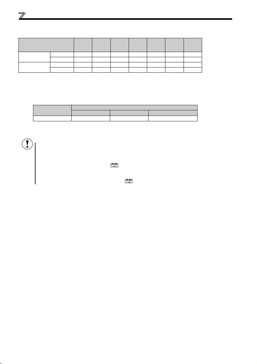
The inverter must be used under the following
environment. Other wise the inverter may be damaged.
Surroundi ng
air
temperature
Ambient
humidity
Storage
temperature
Atmosphere
Environment
Altitude/
vibration
1 Temperature appl icable for a short time, e.g . in transit.
-10°C to +50°C (non-freezing)
90%RH or less (non-condensing)
-20°C to +65°C *1
Indoors (free from corrosi ve gas, flammable gas,
oil mist, dust and dirt)
Maximum 1,000m above sea level.
2
5.9m/s
or less at 10 to 55Hz (directions of X, Y, Z
axes)
A-1
Page 3
(2) Wiring
CAUTION
CAUTION
WARNING
CAUTION
CAUTION
CAUTION
CAUTION
(5) Emergency stop
Do not install a power factor correction capacitor or sur ge
suppressor/capacitor type filter on the inverter output
side. These devices on the inverter output side may be
overheated or burn out.
The connection orientation of the output cables U, V, W to
the motor affects the rotation direction of the motor.
(3) Trial run
Be fore starting operation, each parameter must be
confirmed and adjusted. A failu re to do so may cause
some machines to make unexpected motions.
(4) Usage
An y person must stay away from the equipment wh en the
retry function is set as it will restart suddenly after trip.
S ince pressing key may not stop output dependin g
on the function setting status, separate circ uit and switch
that make an emerg ency stop (power OFF, mechanical
brake operation for emer gency stop, etc.) must be
provided.
OFF status of the start signal must be confirmed before
resetting the inv erter fault. Resettin g inverter alarm wit h
the start signal ON restarts the motor suddenly.
The inverter mu st be used for thre e-phase induction motors.
Connection of any other electrical equipment to the
inverter output may damage the equipment.
Do not modify the equipment.
Do not perform parts removal which is not in structed in this
manual. Doing so may lead to fault or damage of the product.
The electronic thermal relay function does not guarantee
protection of the motor from overheating. It is
recommended to install bo th an external thermal and P TC
thermistor for overh eat protection.
Do not use a magnetic contactor on the inverter input for
frequent starting/stopping of the inverter. Otherwise the
life of the inverter decreases.
T he effect of electrom agnetic interference m ust be
reduced by using a noise filter or by other means.
Otherwise nearby e lectronic equipment may b e affected.
Appr opriate measures must be taken to suppress
harmonics. Otherwise power supply harmonics from the
inverter may heat/dam age the power factor corr ection
capacitor and generator.
W hen driving a 400V class motor by the i nverter, the
motor must be an insulation-enhanced motor or measures
must be taken to suppress surge voltage. Surge voltage
attributable to the wiring constants may occur at the
motor terminals, deteriorating the insulation of the motor.
W hen parameter clear or a ll parameter clear is pe rformed,
the required paramete rs must be set agai n before starting
operations becau se all parameters return t o the initial value.
The inverter can be easily set for high-speed operation.
Before changing its setting, the performances of the
motor and machine must be fully examined.
Stop status cannot be hold by the inverter's brake
function. In addition to t he inverter’s brake function, a
holding device must be installed to ensure safety.
Be fore running an inverter which had been stored for a long
period, inspection and test operation must be performed.
F or prevention of damage due t o static electricity, nearby
metal must be touched before touching this product to
eliminate static electricity from your body.
A s afety backup such as an em ergency brake must be
provided to prevent hazardous condition to the machine
and equipment in ca se of inverter failure.
W hen the breaker on the inverter input side trips, the
wiring must be checked for fault (short circuit), and
internal parts of the inverter for a damage, etc. The cau se
of the trip must be identified and removed before turning
ON the power of the breaker.
W hen any protective function is activated, ap propriate
corrective action must be taken, and the inverter must be
reset before resuming operation.
(6) Maintenance, inspection and parts replacement
Do not carry out a megger (insulation resistance) test on
the control circuit of the inverter. It will cause a failure.
(7) Disposal
T he inverter must be trea ted as industrial waste.
General instruction
Many of the diagrams and dr awings in this Instruction
Manual (Basic) show the inverter without a cover or partially
open for explanation. Never operate the inverter in this
manner. The cover must be alway s reinstalled and the
instruction in this Instruct ion Manual (Basic) must be
followed when operating the inverter.
A-2
Page 4
<Abbreviation>
PU: Operatio n panel and parameter unit (FR-PU04, FR-PU07)
Inverter: Mitsubishi inverter FR-E700 series safety stop function model
FR-E700: Mitsubishi inverter FR-E700 series safety stop function model
Pr.: Parameter number (Number assigned to function)
PU operation: Operation using the PU (operation panel/FR-PU04/FR-PU07)
External operation: Operation using the control circuit signals
Combined operation : Operation using the PU (FR-PU04/FR-PU07) and external operation
Standard motor : SF-JR
Constant torque motor : SF-HRCA
<Trademark>
LONWORKS® is a registered trademark of Echelon Corporation in the U.S.A and other countries.
Company and product names herein are the trademarks and registered trademarks of their respective owners.
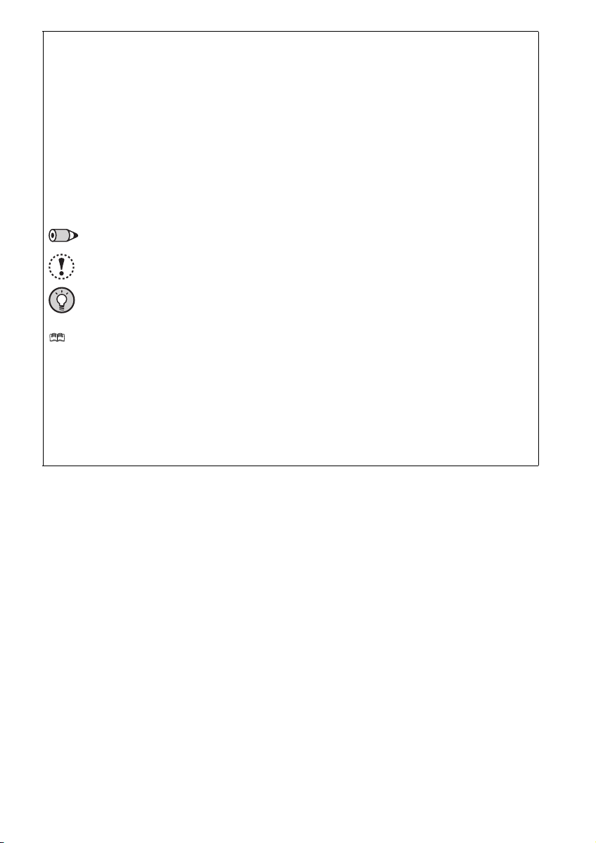
<Mark>
REMARKS: Additional helpful contents and relations with other functions are written.
Note: Contents requiring caution or cases when set functions are not activated are written.
POINT: Useful contents and points are written.
<Related document>
Refer to the Instruction Manual (Applied) for further information on the following points.
Removal and reinstallation of the cover
Connection of stand-alone option unit
EMC and leakage currents
Detailed explanation on parameters
Troubleshooting
Check first when you have a trouble
Inspection items (life diagnosis, cooling fan replacement)
Measurement of main circuit voltages, currents and powers
For customers who are replacing the conventional model with this inverter
A-3
Page 5
1
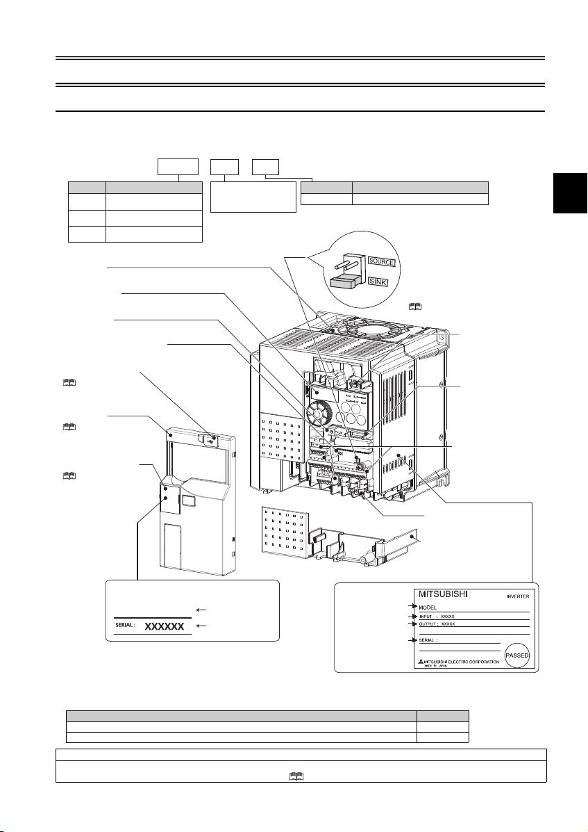
Product checking and parts identification
Cooling fan
The cooling fan is removable.
USB connector
(mini-B conne ctor)
(Refer to page 9)
Control logic switchover jumper
connector
The jumper connector is in the sink logic
(SINK) when shipped from the factory.
Move the jumper connector to change to
the source logic (SOURCE). Always fit the
jumper connector to the either position.
( Refer to the Instruction Manual (Applied))
Combed shaped wiring cover
Refer to the Instruction Manual
(Applied) for installation/removal.
Main circuit terminal block
(Refer to page 10)
PU connector cover
Refer to the
Instruction Manual
(Applied) for how to
open the cover.
Front cover
Refer to the Instruc tion
Manual (Applied) for
installation/removal.
USB connector cover
Refer to the Instruction
Manual (Applied) for how to
open the cover.
Voltage/current input switch
(Refer to page 9)
Operation panel
(Refer to page 2)
PU connector
(Refer to page 9)
Example of FR-E740-3.7KSC
Control circuit terminal
block
(Refer to page 10)
1 OUTLINE
1.1 Product checking and parts identification
Unpack the inverter and check the capacity plate on the front cover and the rating plate on the inverter side face to ensure that
the product agrees with your order and the inverter is intact.
Inverter model
--
No. Voltage class
Three-phase 200V class
E720
Three-phase 400V class
E740
Single-phase 200V class
E720S
E740 3.7 KFR
Represents the
inverter capacity [kW]
SC
Control circuit terminal specificationSymbol
Safety stop function modelSC
Accessory
· Fan cover fixing screws (M3 35mm)
These screws are necessary for compliance with the EU Directive
FR-E720-1.5KSC to 3.7KSC, FR-E740-1.5KSC to 3.7KSC, FR-E720S-0.75KSC to 2.2KSC 1
Harmonic suppression guideline (when inverters are used in Japan)
All models of general -purpose inverters used by specific consumers are covered by "Harmonic suppr ession guideline for cons umers who
receive high voltage or spe cial high voltage". (For furth er details, refer to Chapter 3 of the Instruction Manual (Applied).)
Capacity plate
FR-E740-3.7KSC
Inverter model
Serial number
Rating plate
Inverter model
Input rating
Output rating
Serial number
(Refer to page 49)
Capacity Quantity
FR-E720-5.5KSC to 15KSC, FR-E740-5.5KSC to 15KSC 2
Connector for plug-in
option connection
(Refer to the instruction
manual of options.)
FR-E740-3.7KSC
1
Page 6
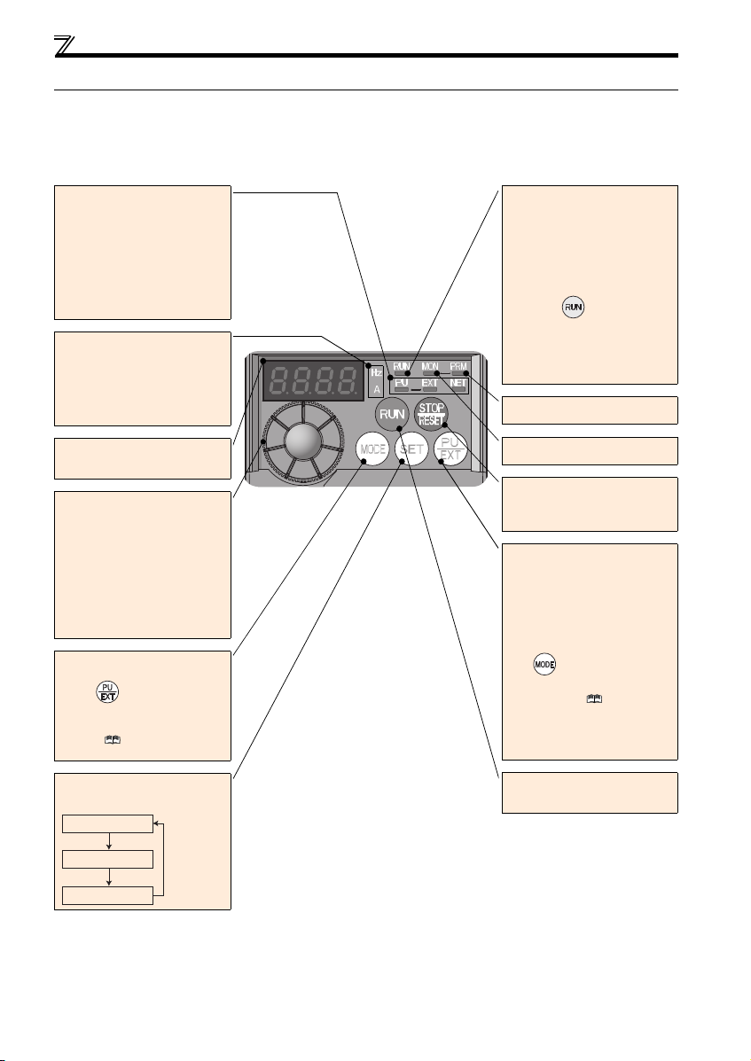
Operation panel
Operation mode indicator
PU: Lit to indicate P U operation mode.
EXT:
Lit to indicate External operation mode.
(Lit at power-ON at initial setting.)
NET: Lit to indicate Network operation
mode.
PU, EXT: Lit to indicate External/PU
combined operation mode 1, 2.
These turn OFF whe n command source is
not on oper ation panel.
Unit indicator
Hz: Lit to indica te frequency.
(Flickers when the set frequency
monitor is displayed.)
A: Lit to indicate current.
(Both "Hz" and "A" turn OFF when other
than the above is displayed.)
Monitor (4-digit LED)
Shows the f requency, parameter numb er,
etc.
Setting dial
(Setting dial: Mitsubishi inverter dial)
Used to change the frequency setting and
parameter settings.
Press to displ ay the following.
Displays the set frequency in the
monitor mode
Present set value is displayed during
calibration
Displays the order in the faults history
mode
Mode switch over
Used to change each setting mode.
Pressing simultaneously changes
the operation mode.
Pressing for a while (2s) can lock
operation. ( Refer to the Instruction
Manual (Applied))
Determination of each setting
If pressed during operation, monitor
changes as below:
Running frequency
Output current
Output voltage
Operating status indicator
Lit or flicker during inverter operation.
* Lit: When the forward rotation operation
is being performed.
Slow flickering (1.4s cycle):
When the reverse operation is being
performed.
Fast flickering (0.2s cycle):
When was pressed or the
start command was given, but the
operation cannot be made.
When the frequency command is less
than the starting frequency.
When the MRS signal is input.
Parameter setting mode
Lit to indicate paramete r setting mode.
Monitor indicator
Lit to indicate monitoring mode.
Stop operation
Used to stop Run command.
Fault can be reset when protective
function is activated (fault).
Operation mode switchover
Used to switch between the PU and
External operation mode.
When using the External operation mode
(operati on using a separa tely connecte d
frequency setting potentiometer and start
signal), press this key to light up t he EXT
indication.
(Press simultaneously (0.5s) o r
change Pr. 79 setting to change to
combined mode .) ( Refer to the
Instruction Manual (Applied))
PU: PU oper ation mode
EXT:External operation mode
Cancels PU stop also.
Start command
The rotation direction can be selected by
setting Pr. 40.
1.2 Operation panel
1.2.1 Names and functions of the operation panel
The operation panel cannot be removed from the inverter.
2
Page 7
1
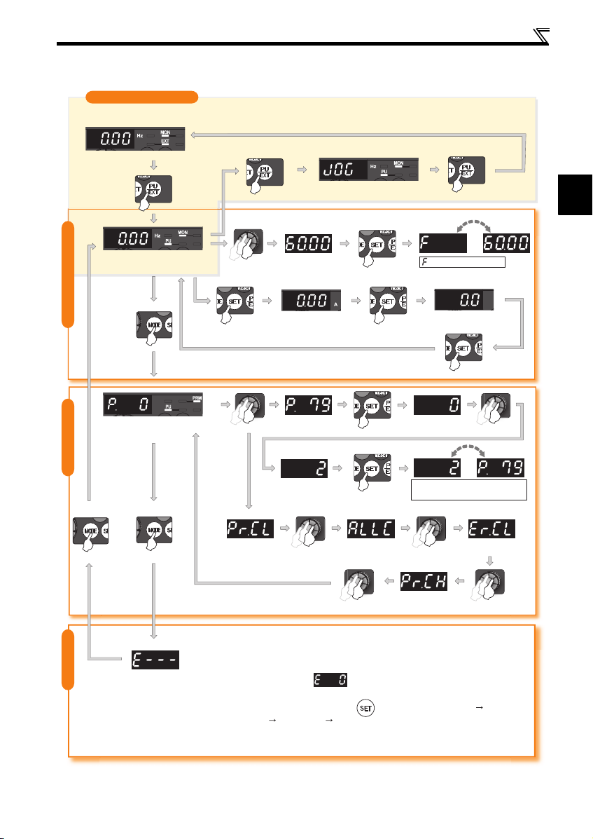
1.2.2 Basic operation (factory setting)
(Refer to page 40)
(Refer to page 4)
Operation mode switchover
At power-ON (External operation mode)
Operation panel
PU Jog operation mode
(Example)
PU operation mode
(output frequency monitor)
Parameter setting mode
Value change
Output current monitor
STOP
and frequency flicker.
Frequency setting has been
written and completed!!
Output voltage monitor
Display the
present setting
(Example)
Parameter settingFaults history Monitor/frequency setting
Value change
Parameter clear All parameter
clear
Parameter and a setting value
flicker alternately.
Parameter write is completed!!
Faults history clear
Initial value
change list
[Operation for displaying faults history]
Past eight faults can be displayed.
(The latest fault is ended by ".".)
When no fault history exists, is displayed.
While a fault is displayed:
The display shifts as follows by pressing : Output frequency at the fault
Output current Output voltage Energization time.
(After Energization time, it goes back to a fault display.)
Pressing the setting dial shows the fault history number.
3
Page 8
Operation panel
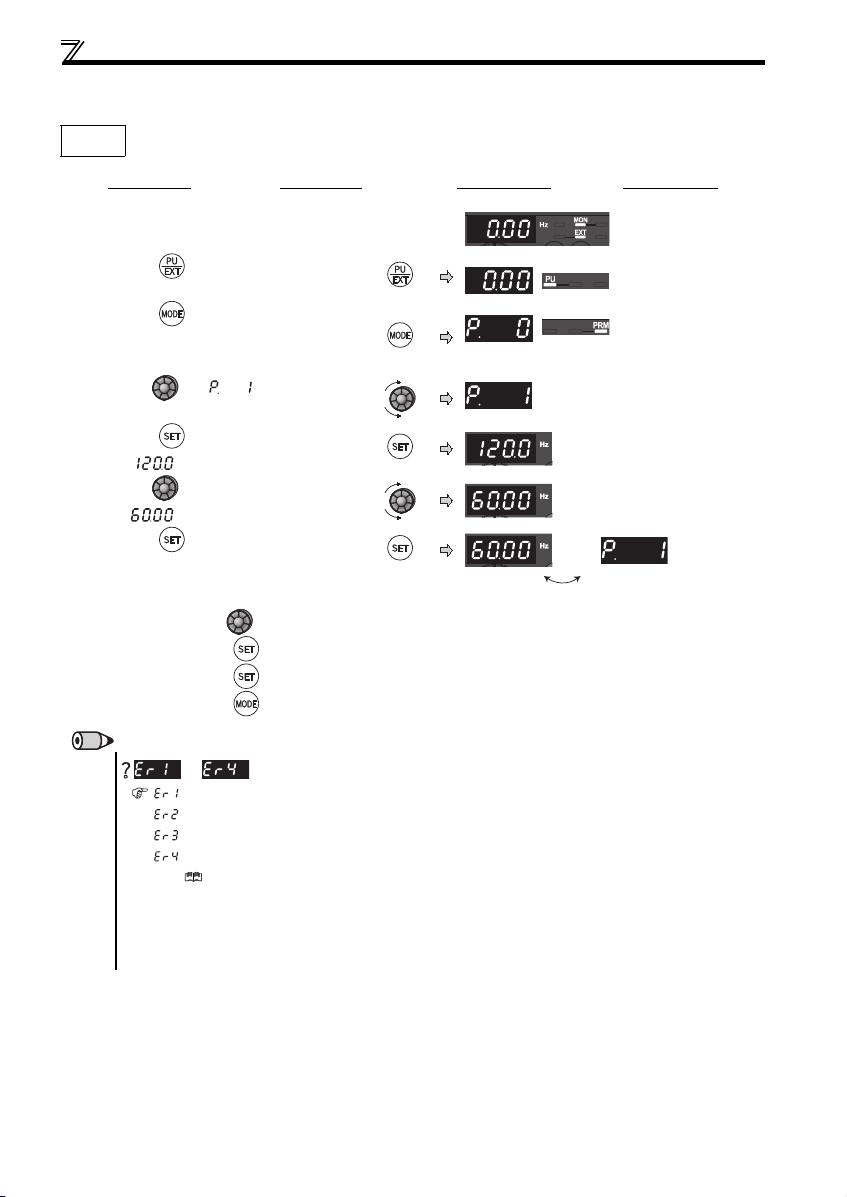
1.2.3 Changing the parameter setting value
Changing
example
Change the Pr. 1 Maximum frequency setting.
Operation Display
1.
Screen at power-ON
The monitor display ap pears.
2. P ress to choose the PU operation mo de.
3. P ress to choose the parameter setting
mode.
4. Turn until (Pr. 1) appears.
5. P ress to read the currently set value.
" "(120.0Hz (initial value) ) appears.
6. Turn to change the set v alue to
" " (60.00Hz).
7. P ress to set.
Turn to read another parameter.
Press to show the setting again.
Press twice to show the next parame ter.
Press twice to return the monito r to frequency monitor.
PU indicator is lit.
PRM indicator is lit.
(The parameter number re ad previously appears.)
Flicker...Parameter setting complete!!
REMARKS
to
appears .................... Write disable error
appears .................... Write error during operat ion
appears ....................Ca libration error
appears ....................M ode designation error
(For details, Refer to the Instruction Manual (Applied) .)
The number of digits displayed on the operation panel is four. Only the upper four digits of values can be displayed and set. If the
values to be displayed have five digits or more including decimal places, the fifth or later numerals can not be displayed nor set.
(Example ) For Pr. 1
When 60Hz is set, 60. 00 is displayed.
When 120Hz is set, 12 0.0 is displayed and second decimal place is not dis played nor set.
is displayed...Why?
4
Page 9
1
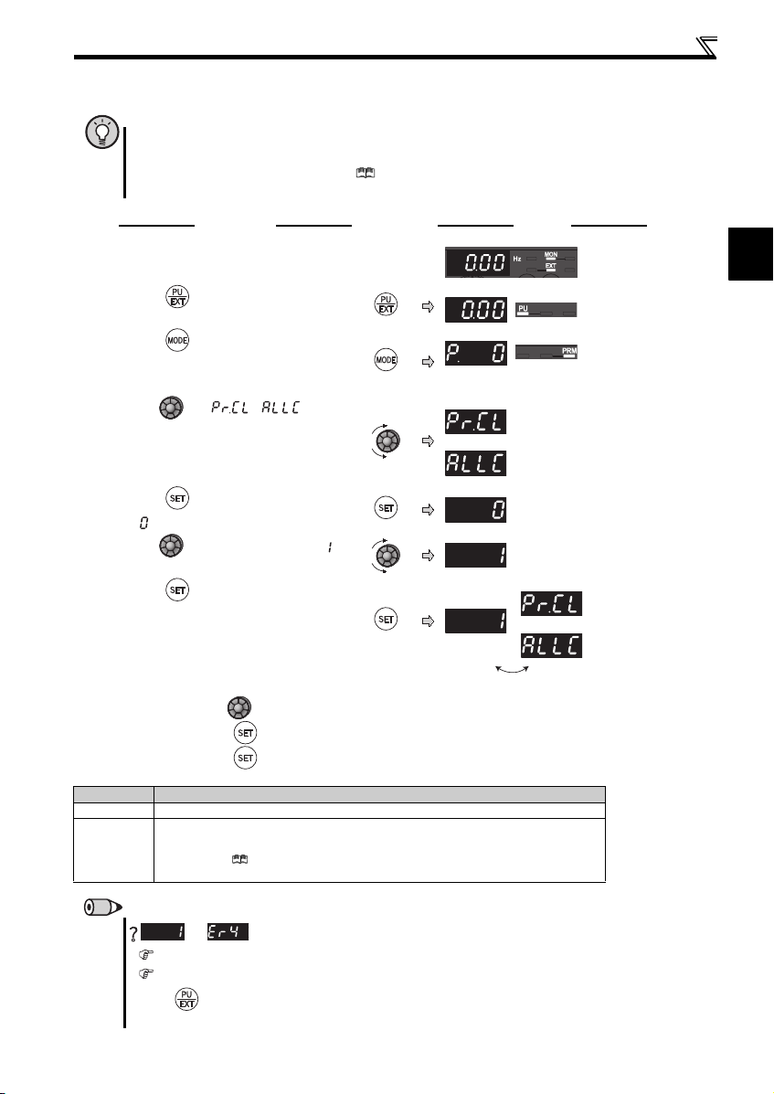
1.2.4 Parameter clear/all parameter clear
and
POINT
Set "1" in Pr.CL Parameter clear, ALLC all parameter clear to initialize all par ameters. (Parameters are not cleared
when "1" is set in Pr. 77 Parameter write selection.)
Refer to the extended parameter list of the Instruction Manual (Applied) for parameters cleared with this
operation.
Operation Display
1.
Screen at power-ON
The monitor display app ears.
2. Press to choose th e PU operation mode.
Operation panel
PU indicator is lit.
3. Press to choose t he parameter setting
mode.
4. Turn until ( ) appears.
PRM indic ator is lit.
(The parameter number r ead previously appears.)
Parameter clear
All parameter clear
5. Press to read the c urrently set value.
" "(initial value) appears.
6. Turn to change it to the set val ue " ".
7. Press to set.
Flicker ··· Parameter setting complete!!
Turn to read another parameter.
Setting Description
0 Not executed.
1
Press to show the setting again.
Press twice to show the next paramet er.
Sets parameters back to the i nitial values. (Paramet er clear sets back all paramete rs except
calibration parameters and term inal function selection parameters to the initial values.) Refer to the
parameter list of the I nstruction Manual (Applied) for availabi lity of parameter clear and a ll
parame ter cl ear.
Parameter clea r
All parameter clear
REMARKS
are displayed alternately ... Why?
The inverter is not in the PU operation mode.
PU connector or USB c onnector is used.
1. Press . [PU] is lit and the monitor (4-digit LED) displays "1". ( When Pr. 79 = "0" (initial value))
2. Carry out operation from step 6 again.
5
Page 10
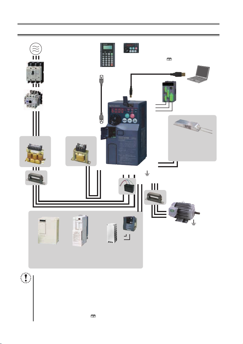
2 INSTALLATION AND WIRING
EMC filter (ferrite core)
(FR-BSF01, FR-BLF)
Install
an EMC filter (ferrite core)
to reduce the electromagnetic
noise generated from the inverter.
Effective in the range from about
1MHz to 10MHz. A wire should be
wound four turns at a maximum.
Motor
Earth (Ground)
Earth (Ground)
Devices connected to the output
Do not install a power factor correction capacitor,
surge suppressor or capacitor type filter on the output
side of the inverter. When installing a moulded case
circuit breaker on the output side of the inverter,
contact each manufacturer for selection of the
moulded case circuit breaker.
The regenerative braking capability
of the inverter can be exhibited fully.
Install this as required.
Power supply harmonics
can be greatly suppressed.
Install this as required.
High power factor
converter (FR-HC)
Power regeneration
common converter
(FR-CV)
Earth (Ground)
R/L1 S/L2T/L3
P1
UW
PR
V
Great braking capability
is obtained.
Install this as required.
EMC filter (ferrite core) *
(FR-BSF01, FR-BLF)
AC power supply
Use within the permissible power supply
specifications of the inverter. To ensure
safety, use a moulded case circuit breaker,
earth leakage circuit breaker or magnetic
contactor to switch power ON/OFF.
Magnetic contactor (MC)
Install the magnetic contactor to ensure
safety. Do not use this magnetic contactor
to start and stop the inverter. Doing so will
cause the inverter life to be shorten.
Moulded case circuit breaker
(MCCB) or earth leakage circuit
breaker (ELB), fuse
The breaker must be selected carefully
since an in-rush current flows in the
inverter at power ON.
Install
an EMC filter (ferrite core)
to reduce the electromagnetic
noise generated from the
inverter. Effective in the range
from about 1MHz to 10MHz.
When more wires are passed
through, a more effective result
can be obtained. A wire should
be wound four turns or more.
To prevent an electric shock, always earth (ground)
the motor and inverter. For reduction of induction noise
from the power line of the inverter, it is recommended
to wire the earthing cable by returning it to the earth
(ground) terminal of the inverter.
AC reactor (FR -HAL)
DC reactor (FR-HEL) *
EMC filter
(capacitor) *
(FR-BIF)
P/+
P/+
PR
PR
Brake unit
(FR-BU2)
Reduces the
radio noise.
Resistor unit (FR-BR)
Discharging resistor (GZG, GRZG)
Inverter (FR-E700)
* Filterpack (FR-BFP2), which contains DC reactor and EMC filter in one package, is also available.
Approved safety
relay module
Required for
compliance with
safety standard.
S1
S2
SC
Parameter unit
(FR-PU07)
USB connector
A personal computer and an inverter
can be connected with a
USB (Ver1. 1) cable.
Enclosure surface operation panel
(FR-PA07)
By connecting the connection cable (FRCB2) to the PU connector, operation can
be performed from FR-PU07, FR-PA07.
Reactor (FR-HAL, FR-HEL option)
Reactors (option) must be used when
power harmonics measures are taken,
the power factor is to be improved or the
inverter is installed near a large power
supply system (500kVA or more). The
inverter may be damaged if you do not
use reactors. Select the reactor according
to the model. Remove the jumpers across
terminals P/+ and P1 to connect the DC reactor.
P/+
P/+
P/+
N/-
(Refer to page 46)
(Refer to page 7)
(Refer to page 7)
( Refer to Chapter 4 of the
Instruction Manual (Applied))
Brake resistor
(FR-ABR, MRS type, MYS type)
Braking capabili ty can be improved. (0.4K
or higher)
Always install a t hermal relay when using
a brake resistor whose capacity is 11K or
higher.
(Refer to page 19)
NOTE
The life of the inverter is influenced by surrounding air temperature. The surrounding air temperature should be as low as
6
possible within the p ermissible range. This m ust be noted especi ally when the inverter is installed in an enclosur e. (Refer
to page 8)
Wrong wiring might lead to damage of the inverter. The control signal lines must be kept fully away from the main circuit
to protect them from noise. (Refer to page 9)
Do not install a power factor correction capacitor, surge suppressor or capacitor type filter on the inverter output side.
This will cause the i nverter to trip or the c apacitor and surge suppress or to be damaged. I f any of the above dev ices are
connected, immediately remove them.
Electromagne tic wave interference
The input/output (main circuit) of the inverter includes high frequency components, which may interfere with the
communication devices (such as AM radios) used near the inverter. In this case, install options among the capacitor type
EMC filter FR-BIF (for use in the input side only), the ferrite core type EMC filter FR-BSF01/FR-BLF, filterpack, and EMC
filter to minimize the interferen ce. ( Refer to Chapter 3 of the Instruction Manual (Applied)).
Refer to the instructi on manual of each option and peripher al devices for details of peripheral devi ces.
Page 11
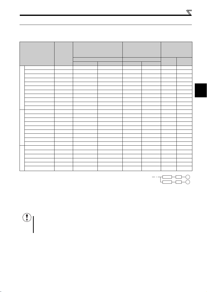
2
Peripheral devices
MCCB INV
MCCB INV
IM
IM
2.1 Peripheral devices
Check the inverter model of the inverter you purchased. Appropriate peripheral devices must be selected according to the capacity.
Refer to the following list and prepare appropriate peripheral devices.
Moulded Case Circuit Breaker
Applicable Inverter
Model
Motor
Output
(kW)
or Earth Leakage Circuit Breaker
(MCCB)
(ELB)
Reactor connection Reactor connection
without with without with
FR-E720-0.1KSC 0.1 5A 5A S-N10 S-N10 0.4K 0.4K
FR-E720-0.2KSC 0.2 5A 5A S-N10 S-N10 0.4K
FR-E720-0.4KSC 0.4 5A 5A S-N10 S-N10 0.4K 0.4K
FR-E720-0.75KSC 0.75 10A 10A S-N10 S-N10 0.75K 0.75K
FR-E720-1.5KSC 1.5 15A 15A S-N10 S -N10 1.5K 1.5K
FR-E720-2.2KSC 2.2 20A 15A S-N10 S -N10 2.2K 2.2K
FR-E720-3.7KSC 3.7 30A 30A S-N20, S-N21 S-N 10 3.7K 3.7K
FR-E720-5.5KSC 5.5 50A 40A S-N25 S-N20, S-N21 5.5K 5.5K
Three-Phase 200V
FR-E720-7.5KSC 7.5 60A 50A S-N25 S -N25 7.5K 7.5K
FR-E720-11KSC 11 75A 75A S-N35 S-N35 11K 11K
FR-E720-15KSC 15 125A 100A S-N50 S-N50 15K 15K
FR-E740-0.4KSC 0.4 5A 5A S-N10 S-N10 H0.4K H0.4K
FR-E740-0.75KSC 0.75 5A 5A S-N10 S -N10 H0.75K H0.75K
FR-E740-1.5KSC 1.5 10A 10A S-N10 S -N10 H1.5K H1.5K
FR-E740-2.2KSC 2.2 15A 10A S-N10 S -N10 H2.2K H2.2K
FR-E740-3.7KSC 3.7 20A 15A S-N10 S -N10 H3.7K H3.7K
FR-E740-5.5KSC 5.5 30A 20A S-N20, S-N21 S-N11, S-N12 H5. 5K H5.5K
FR-E740-7.5KSC 7.5 30A 30A S-N20, S-N21 S-N20, S-N21 H7.5K H7.5K
Three-Phase 400V
FR-E740-11KSC 11 50A 40A S-N20, S-N21 S-N2 0, S-N21 H11K H11K
FR-E740-15KSC 15 60A 50A S-N25 S-N20, S-N21 H15K H15K
FR-E720S-0.1KSC 0.1 5A 5A S-N10 S-N10
FR-E720S-0.2KSC 0.2 5A 5A S-N10 S-N10
FR-E720S-0.4KSC 0.4 10A 10A S-N10 S-N10
FR-E720S-0.75KSC 0.75 1 5A 10A S -N10 S-N10 1.5K 1.5K
FR-E720S-1.5KSC 1.5 20A 20A S-N10 S-N10 2.2K 2.2K
FR-E720S-2.2KSC 2.2 40A 30A S-N20, S-N21 S-N 10 3.7K 3.7K
Single-Phase 200V
Select an MCCB according to the power supply capacity.
Install one MCCB per inverter.
For the use in the United States or Canada, select a UL and cUL certified fuse with Class T fuse equivalent cut-off
speed or faster with the appropriate rating for branch circuit protection. Alternatively, select a UL489 molded case circuit breaker (MCCB). (Refer to page 52)
Magnetic contactor is selected based on the AC-1 class. The electrical durability of magnetic contactor is 500,000 times. When the magnetic contactor is
used for emergency stop during motor driving, the electrical durability is 25 times.
When using the MC for emergency stop during motor driving or using on the motor side during commercial-power supply operation, select the MC with c lass
AC-3 rated current for the motor rated current.
The power factor may be slightly lower.
NOTE
When the inver ter capacity is larger than t he motor capacity, select an MCCB and a m agnetic contactor according t o
the inverter model and cable and reactor according to the motor output.
When the breaker on the inverter input side trips, check for the wiring fault (short circuit), damage to internal parts of
the inverter, etc. Identify the ca use of the trip, then rem ove the cause and power O N the breaker.
Magnetic Contactor (MC)
Reactor
FR-HAL FR-HEL
0.4K
0.4K
0.4K
0.4K
0.4K
0.75K
0. 75K
7
Page 12
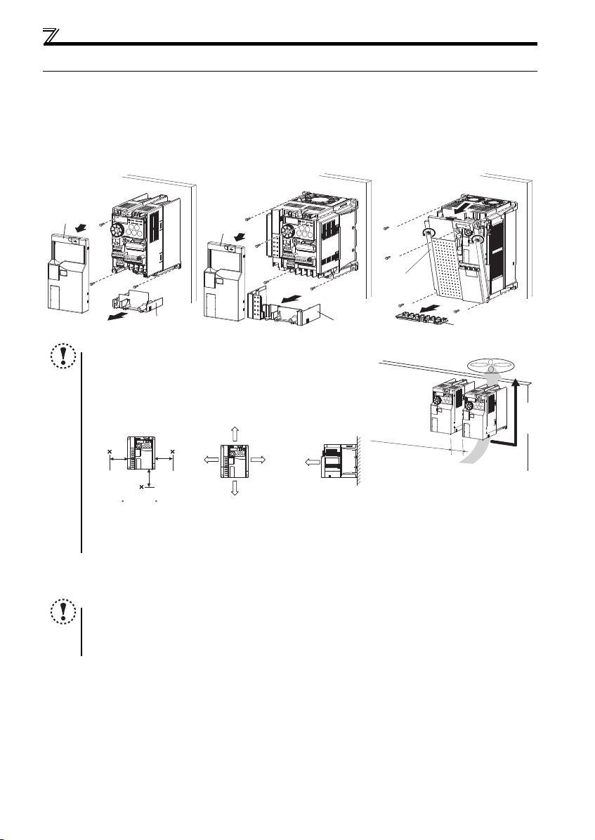
Installation of the inverter and instructions
Front cover
Wiring cover
Front cover
Wiring cover
FR-E720-0.1KSC to 0.75KSC
FR-E720S-0.1KSC to 0.4KSC
FR-E720-1.5KSC to 3.7KSC
FR-E740-0.4KSC to 7.5KSC
FR-E720S-0.75KSC or higher
Front cover 1
FR-E720-5.5KSC to 15KSC
FR-E740-11KSC, 15KSC
Wiring cover
Refer to the clearances
shown on the left.
Vertical
10cm or more
10cm or more
Measurement
position
Measurement
position
5cm
5cm
5cm
-10 C to +50 C
(non-freezing)
1cm or
more
∗1, ∗2
1cm or
more
∗1, ∗2
1cm or
more
∗1
2.2 Installation of the inverter and instructions
(1) Installation of the inverter
Enclosure surface mounting
Remove the front cover and wiring cover to fix the inverter to the surface. (Remove the covers in the directions of the arrows.)
Note
When encasing multi ple inverters, install them in parallel as a cooling
measure.
Install the inverter ve rtically.
For heat dissipation and maintenance, tak e at least the clear ances
shown in the table below from the inverter to the other devices and to
the enclosure surface .
Take 5cm or more clearances for 5.5K or higher.
When using the inverters at the surrounding air temperature of 40C or less, the inverters can be installed without any clearance between
(2) Environment
Before installation, che ck that the environment meets the specifications on page 47.
Note
Install the inverter on a strong surface securely and vertically with bolts.
Leave enough clearances and take cooling measures.
Avoid places where the inverter is subjected to direct sunlight, high temperature and high humidity.
8
Install the inverter on a nonflammable wall surface.
them (0cm clearance).
Page 13
2
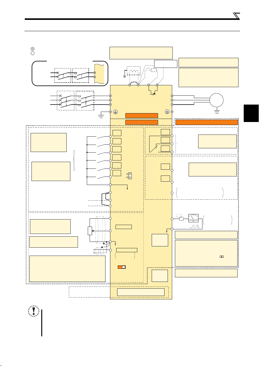
2.3 Wiring
Earth
(Ground)
Motor
IM
Earth (Ground)
Three-phase
AC power
supply
MCCB MC
R/L1
P1 P/+
PR
N/-
S/L2
T/L3
U
V
W
Earth
(Ground)
*7 Brake resistor (FR-ABR, MRS, MYS type)
Install a thermal relay to prevent an
overheat and burnout of the brake resistor.
(The brake resistor can not be connected
to the 0.1K and 0.2K.)
*6 A brake transistor is not built-in to the 0.1K
and 0.2K.
Forward
rotation start
Reverse
rotation start
Middle
speed
High
speed
Low
speed
Reset
Control input signals (No voltage input allowed)
Contact input common
STR
STF
RH
RM
RL
RES
Relay output
Running
Frequency detection
Open collector output
Open collector output common
Sink/source common
FU
RUN
SE
A
B
C
FM
SD
Indicator
(Frequency meter, etc.)
+
-
Moving-coil type
1mA full-scale
Calibration resistor
Frequency setting signals (Analog)
2 0 to 5VDC
10(+5V)
2
3
1
Frequency
setting
potentiometer
1/2W1kΩ
5(Analog common)
*4
Connector for
plug-in option connection
Option connector
*3 Terminal input specifications
can be changed by analog
input specifications
switchover (Pr. 73).
*2 When using terminals PC-
SD as a 24VDC power
supply, take care not to
short across terminals
PC-SD.
PU
connector
*1. DC reactor (FR-HEL)
When connecting a DC reactor, remove the
jumper across P1 and P/+.
Control circuit terminal
Main circuit terminal
Sink logic
Jumper
*1
*7
*6
*3
*8
*9
USB
connector
*10
Terminal functions vary
with the input terminal
assignment (Pr. 178 to
Pr. 182 and Pr. 184)
Multi-speed selection
Terminal functions vary with
the output terminal assignment
(Pr. 190 and Pr. 191)
Terminal functions vary
by Pr. 192 A,B,C terminal
function selection
SINK
SOURCE
VI
*5
(0 to 10VDC)
Voltage/current
input switch
Main circuit
Control circuit
Safety stop function model
R
SD
Relay output
(Fault output)
Brake unit
(Option)
Single-phase
AC power
supply
MCCB MC
R/L1
S/L2
Single-phase power input
24VDC power supply
(Common for external power supply transistor)
Safety stop input common terminal
PC
*2
S1
S2
Safety stop input (Channel 1)
Shorting wire
Safety stop input (Channel 2)
Terminal 4 input
(Current input)
(+)
(-)
4 4 to 20mADC
*5
0 to 5VDC
0 to 10VDC
*5 Terminal input specifications can be changed by analog
input specifications switchover (Pr. 267). Set the
voltage/current input switch in the "V" position to select
voltage input (0 to 5V/0 to10V) and "I" (initial value) to
select current input (4 to 20mA).
To use terminal 4 (initial setting is current input), set "4"
in any of Pr.178 to Pr.184 (input terminal function selection)
to assign the function, and turn ON AU signal.
*4 It is recommended to use 2W1kΩ
when the frequency setting signal
is changed frequently.
*9 Operation and parameter setting can be
done from the parameter unit (FR-PU07)
and the enclosure surface operation panel
(FR-PA07).
(Use the option cable (FR-CB2 ).)
RS-485 communication can be utilized from
a personal computer and other devices.
*8 It is not necessary when calibrating the
indicator from the operation panel.
*10 A personal computer and an inverter can be
connected with a USB (Ver1.1) cable.
2.3.1 Terminal connection diagram
Wiring
NOTE
To prevent a malfunction caus ed by noise, separate the signal c ables more than 10cm from the power cables. Also
After wiring, wire off cuts must not be left in the inverter.
The output of the single-phase power input model is three-phase 200V.
separate the main circuit w ire of the input side and t he output side.
Wire offcuts can cause an alarm, failure or malfunction. Always keep the inverter clean. When drilling mounting holes
in an enclosure etc., take ca re not to allow chips and other foreign matter to enter the inverter.
9
Page 14
Wiring
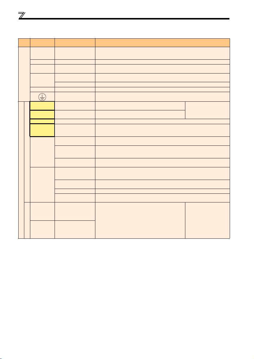
2.3.2 Terminal specifications
Ter mina l
Typ e
Symbol
R/L1, S/L2,
T/L3 *
U, V, W Inverter output Connect a three-phase squirrel-cage motor.
P/+, PR Brake resistor conn ection
P/+, N/-
Main circuit
P/+, P1 DC reactor connection Remove the jumper across terminals P/+ and P1 and connect a DC reactor.
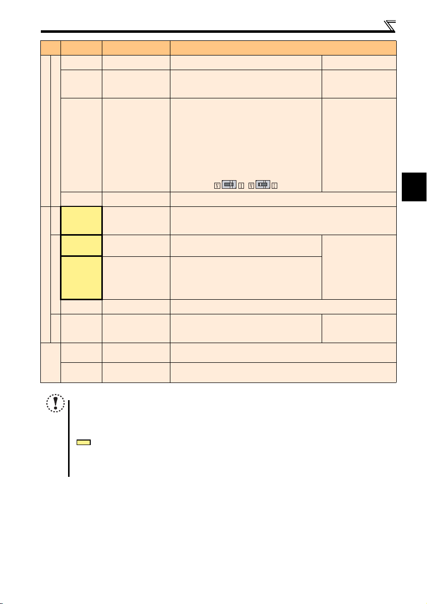
STF Forward ro tation start
STR Reverse rotation start
RH, RM, RL Mu lti-speed selection Multi-speed can be selected according to the combination of RH, RM and RL signals.
RES Reset
SD
Contact input
PC
Control circuit/input signal
S1
S2
Safety stop function *
For more details, refer to the Safety stop function instruction manual (BCN-A211508-004). (Refer to the front cover for how to obtain the manual.)
Term inal Na me Description
AC power input
Brake unit connection
DC power input
Earth (Ground)
Contact input common
(sink) (initial setting)
External transistor
common (source)
24VDC power supply
common
External transistor
common
(sink) (initial setting)
Contact input common
(source)
24VDC power supply
Safety stop input terminal
common
Safety stop input
(Channel 1)
Safety stop input
(Channel 2)
Connect to the commercial power supply. Keep these terminals open when using the high
power factor converter (FR-HC) or power regeneration common converter (FR-CV).
When using single-phase power input, terminals are R/L1 and S/L2.
Connect a brake resistor (MRS type, MYS type, FR-ABR) across terminals P/+ and PR.
(The brake resistor can not be connected to the 0.1K or 0.2K)
Connect the brake unit (FR-BU2), power regeneration common converter (FR-CV) or high
power factor converter (FR-HC).
Connect t he plus sid e of the pow er supply t o terminal P/+ and minu s side to t erminal N/ -.
For earthing (grounding) the inverter chassis. Must be earthed (grounded).
Turn ON the STF signal to start forward rotation and turn it OFF
to stop.
Turn ON the STR signal to start reverse rotation and turn it OFF
to stop.
Used to reset alarm output provided when protective circuit is activated. Turn ON the RES
signal for more t han 0.1s, then tu rn it OFF. Initial setting is fo r reset always. By setting Pr. 75,
reset can be set to enabled only at fault occurrence. Recover about 1s after reset is cancelled.
Common terminal for contact input terminal (sink logic) and terminal FM.
Connect this terminal to the power supply common terminal of a transistor output (open
collector output) device, such as a programmable controller, in the source logic to avoid
malfunction by undesirable current.
Common output terminal for 24VDC 0.1A power supply (PC terminal).
Isolated from terminals 5 and SE.
Connect this terminal to the power supply common terminal of a transistor output (open
collector output) device, such as a programmable controller, in the sink logic to avoid
malfunction by undesirable current.
Common terminal for contact input terminal (source logic).
Can be used as 24VDC 0.1A power supply.
Common terminal for safety stop input terminals S1 and S2.
S1/S2 are safety stop signals for use with in conjunction with
an approved external safety unit. Both S1/S2 must be used in
dual channel form. Inverter output is shutoff depending on
shorting/opening between S1 and PC, S2 and PC.
In the initial status, terminal S1 and S2 are shorted with
terminal PC by shorting wire.
Remove the shorting wire and connect the safety relay module
when using the safety stop function.
When the STF and STR
signals are turned ON
simultaneously, the stop
command i s given.
Input resistance 4.7k
Voltage when contacts are
open
21 to 26VDC
When contacts are shortcircuited
4 to 6mADC
10
Page 15
2
Typ e
Voltage input
Current input
(initial status)
Control circuit/input signa l
Frequency setting
Term ina l
Symbol
10
2
4
Terminal Name Description
Frequency setting power
supply
Frequency setting
(voltage)
Frequency setting
(current)
Used as power supply when connecting potentiometer for
frequency setting (speed setting) from outside of the inverter.
Inputting 0 to 5VDC (or 0 to 10V) provides the maximum output
frequency at 5V (10V) and makes input and output
proportional. Use Pr. 73 to switch betw een input 0 to 5VD C
(initial setting) and 0 to 10VD C input.
Inputting 0 to 20mADC (or 0 to 5V / 0 to 10V) provides the
maximum output frequency at 20mA and makes input and
output proportional. This input signal is valid only when the AU
signal is ON (terminal 2 input is invalid). To use terminal 4
(initial setting is current input), set "4" to any of Pr.178 to Pr.184
(input terminal function selection), a nd turn AU signal O N. Use
Pr. 267 to switch among input 4 to 20mA (initial setting), 0 to
5VDC, and 0 to 10VDC. Set the voltage/current input switch in
the "V" position to select voltage in put (0 to 5V/0 t o 10V).
Wiring
5VDC
permissible load current 10mA
Input resistance 10k ± 1k
Permissible maximum voltage
20VDC
Voltage input:
Input resistance 10k ± 1k
Permissible maximum voltage
20VDC
Current input:
Input resistance 233 ± 5
Maximum permissible current
30mA.
5
A, B, C
Relay
RUN Inverter running
FU Frequency detection
Open collector
Control circuit/output signal
SE
FM For meter
Pulse
— PU co nnector
— USB connector
Communication
Frequency setting
common
Relay output
(fault output)
Open collector
output common
Common terminal for the frequency setting signals (terminals 2 and 4). Do not earth (ground).
1 changeover contact output indicates that the inverter fault occurs.
Fault: discontinuity across B and C (continuity across A and C),
Normal: continuity across B and C (discontinuity across A and C)
Contact capacity 230VAC 0.3A (power factor = 0.4) 30VDC 0.3A
Switched Low when the inverter output frequency is equal to or
higher than the starting frequency (initial value 0.5Hz).
Switched High during stop or DC injection brake operation.
Switched Low when the inverter output frequency is equal to or
higher than the preset detected frequency and High when less
than the pr eset detect ed frequency.
Common terminal of terminal RUN and FU.
Used to output a selected monitored item (such as Output
frequency) among several monitored items. (Not output during
inverter reset.)The output signal is proportional to the
magnitude of the corresponding monitoring item.
With the PU connector, RS-485 communication can be established.
· Conforming standard: EIA-485 (RS-485) · Transmission format: Multi-drop link
· Communication speed: 4800 to 38400bps · Overall extension: 500m
A personal computer and an inverter can be connected with a USB (Ver1.1) cable.
· Interface: conforms to USB1.1 · Transmission Speed: 12Mbps
· Connector: USB mini B connector (receptacle mini B type)
Permissible load 24VDC
(Maximum 27VDC) 0.1A
(a voltage drop is 3.4V
maximum when the signal is
ON)
Low is when the open
collector output transistor is
ON (conducts). High is when
the transistor is OFF (does
not conduct).
Permissible load current 1mA
1440 pulses/s at 60Hz
Note
Set Pr. 267 and a voltage/current input switch correctly, then input an analog signal in accordance with the setting.
Applying a voltage with voltage/current input switch in "I" position (current input is selected) or a current with switch
in "V" position (voltage input is selected) could cause component damage of the inverter or analog circuit of output
devices.
The inverter will b e damaged if power is applied to t he inverter output terminals (U, V, W). Never perform such wiring.
indicates that terminal functions can be selected using Pr. 178 to Pr. 182, Pr. 184 and Pr. 190 to Pr. 192 (I/O terminal
function selection).
Terminal names and termina l functions are those of t he factory set.
When connecting the DC power supply, be sure to connect the plus side of the power supply to terminal P/+ and
minus side to terminal N/-. Opposite polarity will damage the inverter.
11
Page 16
Wiring
MotorPower supply
N/-
P/+ PR
IM
R/L1 S/L2 T/L3
Jumper
Motor
Power supply
IM
N/-
P/+
PR
R/L1 S/L2 T/L3
Jumper
MotorPower supply
N/-
P/+ PR
IM
R/L1 S/L2
Jumper
Motor
Power supply
N/-
P/+
PR
IM
R/L1 S/L2
Jumper
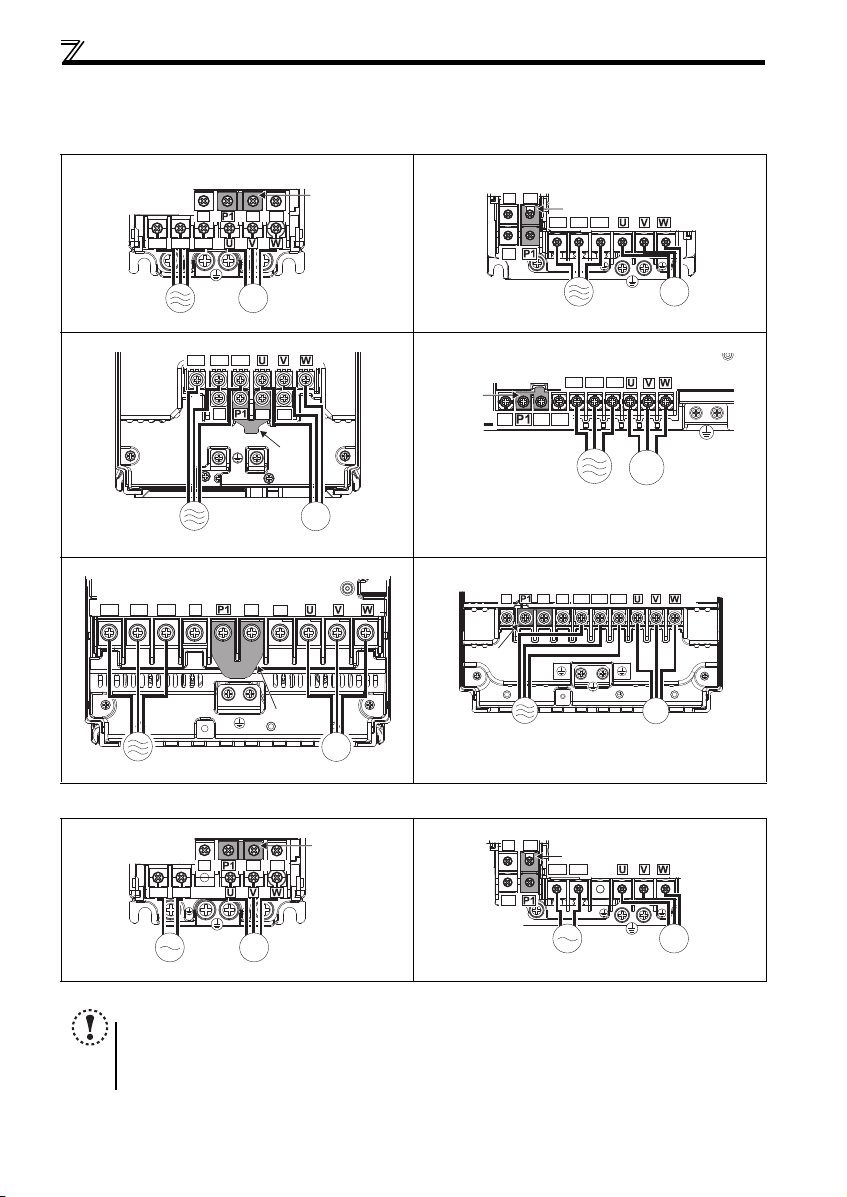
2.3.3 Terminal arrangement of the main circuit terminal, power supply and the motor wiring
Three-phase 200V/400V class
FR-E720-0.1KSC to 0.7 5KSC FR-E720-1.5KSC to 3.7K SC
FR-E740-0.4KSC to 3.7K SC
N/-
P/+
PR
Jumper
R/L1 S/L2 T/L3
IM
Motor
FR-E720-5.5KSC, 7.5K SC FR-E740-5.5KSC, 7.5K SC
R/L1 S/L2 T/L3
N/-
P/+
Jumper
PR
N/-
P/+
Power supply
R/L1 S/L2 T/L3
PR
Jumper
IM
Power supply
FR-E720-11KSC, 15KSC FR-E740-11KSC, 15KSC
R/L1 S/L2 T/L3
N/-
P/+
Motor
PR
Jumper
IM
MotorPower supply
Single-phase 200V class
FR-E720S-0.1KSC to 0 .4KSC FR-E720S-0.75KSC to 2.2KSC
NOTE
Make sure the power cables are connected to the R/L1, S/L2, and T/L3. (Phase need not be matched.) Never connect
12
the power cables to the U, V, and W of the inverter. Doing so will damage the inverter.
Connect the motor to U, V, and W. Turning ON the forward rotation switch (signal) at this time rotates the motor
counterclockwise when viewed from the load shaft.
IM
MotorPower supply
Page 17
2
Wiring
3 × wire resistance[mΩ/m] × wiring distance[m] × current[A]
1000
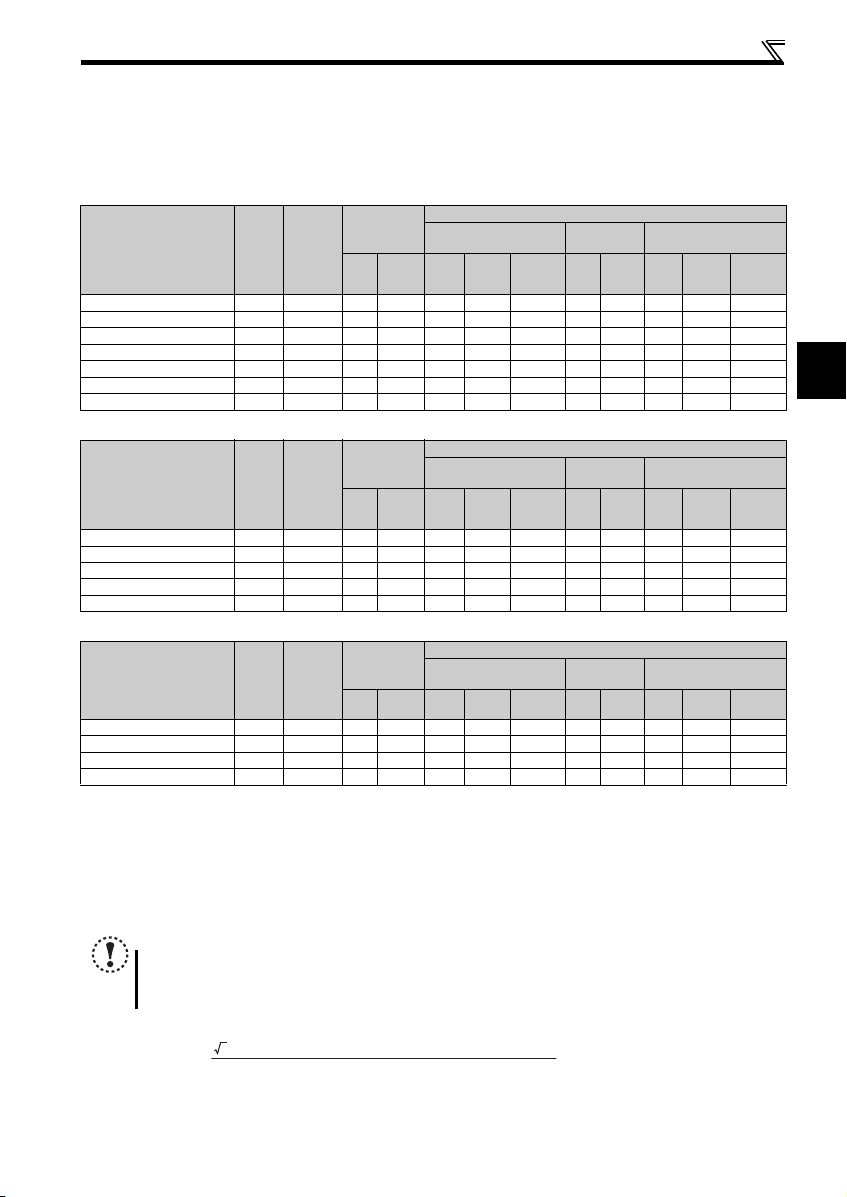
(1) Cable size and other specifications of the main circuit terminals and the earthing terminal
Select the recommended cable size to ensure that a voltage drop will be 2% or less.
If the wiring distance is long between the inverter and motor, a main circuit cable voltage drop will cause the motor torque to
decrease especially at the output of a low frequency.
The following table indicates a selection example for the wiring length of 20m.
Three-phase 200V class (when input power supply is 220V)
cable
cable
cable
Cable Size
AWG
R/L1
S/L2
U, V, W
T/L3
Cable Size
AWG
R/L1
S/L2
U, V, W
T/L3
Cable Size
AWG
R/L1
U, V, W
S/L2
PVC Cables, etc. (mm2)
R/L1
S/L2
T/L3
PVC Cables, etc. (mm2)
R/L1
S/L2
T/L3
PVC Cables, etc. (mm2)
R/L1
S/L2
U, V, W
U, V, W
U, V, W
Earthing
cable
Earthing
cable
Earthing
cable
Crimping
N·m
Ter min al
R/L1
S/L2
T/L3
Ter mi nal
Applicable Inverter
Model
FR-E720-0.1KSC to 0.7 5KSC M 3.5 1.2 2-3.5 2-3.5 2 2 2 14 14 2.5 2.5 2.5
FR-E720-1.5KSC, 2.2K SC M4 1.5 2-4 2-4 2 2 2 14 14 2.5 2.5 2.5
FR-E720-3.7KSC M4 1.5 5.5-4 5.5 -4 3.5 3.5 3.5 12 12 4 4 4
FR-E720-5.5KSC M5 2.5 5.5-5 5.5 -5 5.5 5.5 5.5 10 10 6 6 6
FR-E720-7.5KSC M5 2.5 14-5 8-5 14 8 5.5 6 8 16 10 6
FR-E720-11KSC M5 2.5 14-5 14-5 14 14 14 6 6 16 16 16
FR-E720-15KSC M6(M5) 4.4 2 2-6 22-6 22 22 14 4 4 2 5 25 16
Screw
Size
Tightening
Torque
HIV Cables, etc. (mm2)
R/L1
U, V, W
S/L2
T/L3
U, V, W
Earthing
Three-phase 400V class (when input power supply is 440V)
Crimping
N·m
Ter min al
R/L1
S/L2
T/L3
Ter mi nal
Applicable Inverter
Model
FR-E740-0.4KSC to 3.7 KSC M4 1.5 2-4 2-4 2 2 2 14 14 2.5 2.5 2.5
FR-E740-5.5KSC M4 1.5 5.5-4 2-4 3.5 2 3.5 12 14 4 2.5 4
FR-E740-7.5KSC M4 1.5 5.5-4 5.5 -4 3.5 3.5 3.5 12 12 4 4 4
FR-E740-11KSC M4 1.5 5.5-4 5.5-4 5.5 5.5 8 10 10 6 6 10
FR-E740-15KSC M5 2. 5 8-5 8-5 8 8 8 8 8 1 0 10 10
Screw
Size
Tightening
Torque
HIV Cables, etc. (mm2)
R/L1
U, V, W
S/L2
T/L3
U, V, W
Earthing
Single-phase 200V class (when input power supply is 220V)
N·m
Crimping
Ter min al
R/L1
S/L2
HIV Cables, etc. (mm2)
R/L1
U, V, W
S/L2
U, V, W
Earthing
Ter mi nal
Applicable Inverter
Model
FR-E720S-0.1KSC to 0.4KS C M3.5 1. 2 2-3.5 2-3.5 2 2 2 14 14 2.5 2.5 2.5
FR-E720S-0.75KSC M4 1. 5 2-4 2-4 2 2 2 1 4 14 2.5 2.5 2.5
FR-E720S-1.5KSC M4 1.5 2-4 2-4 2 2 2 14 14 2.5 2.5 2.5
FR-E720S-2.2KSC M4 1.5 5.5-4 2-4 3.5 2 2 12 14 4 2.5 2.5
The cable size is that of the cable (HIV cable (600V class 2 vinyl-insulated cable) etc.) with continuous maximum permissible temperature of 75°C. Assumes
that the surrounding air temperature is 50°C or less and the wiring distance is 20m or less.
The recommended cable size is that of the cable (THHW cable) with continuous maximum permissible temperature of 75°C. Assumes that the surrounding air
temperature is 40°C or less and the wiring distance is 20m or less. (Selection example for use mainly in the United States.)
The recommended cable size is that of the cable (PVC cable) with continuous maximum permissible temperature of 70°C. Assumes that the surrounding air
temperature is 40°C or less and the wiring distance is 20m or less. (Selection example for use mainly in Europe.)
The terminal screw size indicates the terminal size for R/L1, S/L2, T/L3, U, V, W, and a screw for earthing (grounding).
A screw for earthing (grounding) of the FR-E720-15KSC is indicated in ( ).
For single-phase power input, the terminal screw size indicates the size of terminal screw for R/L1, S/L2, U, V, W, PR, P/+, N/-, P1 and a screw for earthing
(grounding).
Screw
Size
Tightening
Torque
NOTE
Tighten the terminal screw to the specified torque. A screw that has been tighten too loosely c an cause a short circuit
or malfunction. A screw that has been tighten too tightly can cause a short circuit or malfunction due to the unit
breakage.
Use crimping terminals with insulation sleeve to wire the power supply and motor.
The line voltage drop can be calculated by the following formula:
Line voltage drop [V]=
Use a larger diameter cable when the wiring distance is long or when it is desired to decrease the voltage drop (torque
reduction) in the low speed range.
13
Page 18
Wiring
(2) Total wiring length
The overall wiring length for connection of a single motor or multiple motors should be within the value in the table below.
Pr. 72 PWM frequency selection
Setting
(carrier frequency)
1 (1kHz) or less
2 to15
(2kHz to 14.5kHz)
200V class 200m 200m 3 00m 500m 500m 500m 500m
400V class - - 200m 200m 300m 50 0m 500m
200V class 30m 1 00m 200m 300m 500m 500m 500m
400V class - - 30m 100m 200m 300m 500 m
0.1K 0.2K 0.4K 0.75K 1.5K 2.2K
When driving a 400V class motor by the inverter, surge voltages attributable to the wiring constants may occur at the motor
terminals, deteriorating the insulation of the motor. Take the following measures 1) or 2) in this case.
1) Use a "400V class inverter-driven insulation-enhanced motor" and set frequency in Pr. 72 PWM frequency selection
according to wir ing length.
Carrier frequency 14.5kHz or less 8kHz or less 2kHz or less
50m or less 50m to 100m Exceeding 100m
Wiring Length
2) Connect the surge voltage su ppression filter (FR-ASF-H/FR-BMF-H) o n the inverter output side.
NOTE
Especially for long-distance wiring, the inverter may be affected by a charging current caused by the stray
capacitances of the wiring, leading to a malfunction of the overcurrent protective function, fast response current limit
function, or stall prevention function or a malfunction or fault of the equipment connected on the inverter output side.
If malfunction of fast-response current limit function occurs, disable this function. If malfunction of stall prevention
function occurs, increase the stall level. ( Pr. 22 Stall prevention operation level and Pr. 156 Stall prevention operation
selection in Chapter 4 of the Instruction Manual (Applied))
When using the automatic restart after instantaneous power failure function with the wiring length exceeding 100m,
select without frequen cy search (Pr. 162 = "1, 11"). (
Refer to Chapter 4 of the Instruction Manu al (Applied))
3.7K
or More
14
Page 19

2
2.3.4 Wiring of control circuit
(1) Control circuit terminal layout
Recommend wire size:
0.3mm
2
to 0.75mm
2
Wiring
10 2 5 4
RUN SEFU S1 S2
PC
RL
RES
FM
CBA
RHRM
STF
SD
SD
STR
(2) Wiring method
Wiring
Use a blade terminal and a wire with a sheath stripped off for the control circuit wiring. For a single wire, strip off the sheath of
the wire and apply directly.
Insert the blade terminal or the single wire into a socket of the terminal.
1) Strip off the sheath about the size below. If the length of the sheath peeled is too long, a short circuit may occur
among neighboring wires. If the length is too short, wires might come off.
Wire the stripped wire after twisting it to prevent it from becoming loose. In addition, do not solder it.
Wire stripping length
10mm
2) Crimp the blade terminal.
Insert wires to a blade terminal, and check that the wires come out for about 0 to 0.5 mm from a sleeve.
Check the condition of the blade ter minal after crimping. Do not use a bla de terminal of which the crimping is
inappropriate, or the face is damaged.
Unstranded
Wire
Sleeve
0 to 0.5mm
Shell
Damaged
Crumpled tip
Blade terminals available on the market: (as of Jan. 2010)
Phoenix Contact Co.,Ltd.
Wire Size (mm2)
0.3 AI 0,5-10WH — —
0.5 AI 0,5-10WH — AI 0,5-10WH-GB
0.75 AI 0,75-10GY A 0,75-10 AI 0,75-10GY-GB
1 A I 1-10RD A1-10 AI 1-10RD/1000GB
1.25, 1.5 AI 1,5-10BK A1,5-10 AI 1,5-10BK/ 1000GB
0.75 (for two wires) AI-TWIN 2 x 0,75-10GY — —
A bl ade terminal with an insulation sleeve compatible with MTW wire which has a thick wire insulation
Applicable for terminal ABC.
with insulation sleeve without insulation sleeve for UL wire
Blade Terminal Model
NICHIFU Co.,Ltd.
Wire Size (mm2)
0.3 to 0.75 BT 0.75-11 VC 0.75 NH 67
Blade terminal product
number
Insulation product number
wires
Wires are not inserted
into the shell
Blade terminal
crimping tool
Blade terminal
crimping tool
CRIMPFOX 6
15
Page 20

Wiring
Flathead screwdriver
Open/close button
r
NOTE
Pulling out the terminal block forcefully without pushing
the open/close button all the way down may damage the
terminal block.
Use a small flathead scr ewdriver (Tip thickness: 0.4mm/
tip width: 2.5mm) .
If a flathead screwdriver with a narrow tip is used,
terminal block may be damaged.
Products available on the market :(as of Jan. 2010)
Place the flath ead screwdriver vertical t o the open/close
button. In case the blade tip slips, it may cause to damage of inverter or in jury.
Product Ty pe Maker
Flathead
screwdriver
SZF 0- 0,4 x 2,5 Phoenix Co ntact Co.,Ltd.
3) Insert the wire into a socket.
When using a single wire or a stranded wire without a blade terminal, push an
open/close button all the way down with a flathead screw driver, and insert the wire.
NOTE
When using a stranded wire without a blade terminal, twist enough to avoid short circuit with a nearby terminals or
wires.
Place the flathea d screwdriver vertical to the open/clo se button. In case t he blade tip slips, it ma y cause to damage of
inverter or injury.
Wire removal
Pull the wire with pushing the open/close button all the
way down firmly with a flat head screwdr iver.
Open/close button
Flathead screwdrive
(3) Control circuit common terminals (SD, 5, SE)
Terminals SD, SE and 5 are common terminals for I/O signals. (All common terminals are isolated from each other.) Do not
earth them. Avoid connecting the terminals SD and 5 and the terminals SE and 5.
Terminal SD is a common terminal for the contact input terminals (STF, STR, RH, RM, RL, RES) and frequency output signal
(FM). The open collector circuit is isolated from the internal control circuit by photocoupler.
Terminal 5 is a common terminal for the frequency setting signals (terminal 2 or 4). It should be protected from external noise
using a shielded or twisted wire.
Terminal SE is a common terminal for the open collector output terminal (RUN, FU). The contact input circuit is isolated from
the internal control circuit by photocoupler.
(4) Wiring instructions
1) It is recommended to use the wires of 0.3mm2 to 0.75mm2 gauge for connection to the control circuit terminals.
2) The maximum wiring length should be 30m ( 200m for terminal FM).
3) Do not short terminals PC and SD. Inverter may be damaged.
4) Use two or more parallel micro-signal contacts or twin contacts to prevent
contact faults wh en using contact inputs since the control circui t input signals
are micro-currents.
5) Use shielded or twisted wires for connection to the control circuit terminals and
run them away from the main and power circuits (including the 200V relay
sequence circuit).
6) Do not apply a voltage to the contact input terminals (e.g. STF) of the control
circuit.
7) Always apply a voltage to the fault output terminals (A, B, C) via a relay coil, lamp, etc.
16
Micro signal contacts Twin contacts
Page 21

2
Wiring
S2
S1
PC
Inverter
START/RESET
+24V
QS90SR2SN-Q
K1
X0 X1
COM0
COM1
24G
XS0
XS1
Z10
Z00
Z20
Z11 Z01 Z21
K2
DC24V
RUN(SAFE2)
R S T
U V W
MITSUBISHI MELSEC Safety relay module
IM
SE
STF
STR(STOP)
STF
STOP
SD
I/O control
FU(SAFE)
monitor
*1
*1
*2
*2
Internal
Safety
Circuit
Output shutoff
circuit
*1 Output signals differ by the setting of Pr.190 and
Pr.191 (Output terminal function selection).
*2 Input signals differ by the setting of Pr178 to Pr.182
(Input terminal function selection).
Emergency
stop button
2.3.5 Safety stop function
(1) Description of the function
The terminals related to the safety stop function are shown below.
Terminal Symbol Description
S1
S2
PC
FU
RUN
SE Common terminal for open col lector outputs (terminal RUN and FU)
In the initial status, terminal S1 and S2 are shorted with terminal PC by shortening wire. Remove the shortening wire and connect the safety relay module
when using the safety stop function.
In the initial setting, output frequency detection (FU signal) is assigned to terminal FU. Set "80" to Pr.191 FU terminal function selection to assign SAFE signal.
The function can be assigned to other terminals by setting "80 (positive logic) or 180 (negative logic)" to any of Pr.190 to Pr.192 (Output terminal function
selection). ( Refer to the Instruction Manual (Applied))
In the initial setting, inverter running (RUN signal) is assigned to terminal RUN. Set "81" to Pr.190 RUN terminal function selection to assign SAFE2 signal. The
function can be assigned to other terminals by setting "81 (positive logic) or 181 (negative logic)" to any of Pr.190 to Pr.192 (Output terminal function selection).
( Refer to the Instruction Manual (Applied))
At an internal safety circuit failure, one of E.SAF, E.6, E.7, and E.CPU is displayed on the operation panel.
For input of safety stop c hannel 1.
For input of safety stop c hannel 2.
Common terminal for termi nal S1 and S2.
Outputs the safety stop s tatus
SAFE
The signal is output when i nverter output is shut off due to the
signal
safety stop function.
SAFE2
Outputs when an alarm or failure is detected.
The signal is output when no internal safety circuit failure
signal
NOTE
Hold the ON or OFF status for 2ms or longer to input signal to terminal S1 or S2. Signal input shorter than 2ms is not
recognized.
Use SAFE signal to monitor safety stop status. SAFE signal cannot be used as safety stop input signal to other
devices (other than the safety relay module).
SAFE 2 signal can only be used to output an alarm or to prevent restart of an inverter. The signal cannot be used as
safety stop input sig nal to other devices.
(2) Wiring connection diagram
To prevent restart at fault occurrence, connect terminals RUN (SAFE 2 signal) and SE to terminals XS0 and XS1, which are
the feedback input terminals of the safety relay module.
By setting Pr. 190 RUN terminal function selection = "81 (SAFE2 signal)", terminal RUN is turned OFF at fault occurrence.
Between S1 and PC / S2 and PC
Open: In safety stop state .
Short: Other than safety s top state.
OFF: Drive enabled or dr ive stop (at an internal
safety circuit failure
ON: Drive stop (no interna l safety circuit failure
OFF: Internal safety circ uit failure
exists.
ON : No internal safety cir cuit failure
)
)
NOTE
Changing the terminal assignment using Pr. 190 to Pr. 192 (output terminal function selection) may affect the other
functions. Set parameters after confirming the function of each terminal.
17
Page 22

Wiring
(3) Safety stop function operation
Input
power
OFF — — — OFF OFF Output shutoff (Safe state)
ON
At an internal safety circuit failure, one of E.SAF, E.6, E.7, and E.CPU is displayed on the operation panel.
SA is displayed when both of the S1 and S2 signals are in open status and no internal safety circuit failure exists.
ON: Transistor used for an open collector output is conducted.
OFF: Transistor used for an open collector output is not conducted.
For more details, refer to the Safety stop function instruction manual (BCN-A211508-004). (Please contact your sales
representative for the manual.)
Input sign al
S1-PC S2-PC SAFE SAFE2
Short Short
Open Open
Short Open Failure OFF O FF Output shu toff (Safe state)
Open
Short Failure OFF OF F Output shu toff (Safe state)
Internal safety circuit
No failure OFF ON Drive enabled
Failure OFF OFF Output shutoff (Safe state)
No failure ON O N Output shutoff (Safe state)
Failure OFF OFF Output shutoff (Safe state)
Output signal
Inverter operation enable signal
18
Page 23

2
Connection of a dedicated external brake resistor (MRS type, MYS type, FR-ABR)
Thermal relay
(OCR) (*1)
*2
Thermal re lay
(OCR) (*1)
*2
r
2.4 Connection of a dedicated external brake resistor (MRS type, MYS type, FR-ABR)
Install a dedicated brake resistor (MRS type, MYS type, FR-ABR) outside when the motor driven by the inverter is made to run
by the load, quick deceleration is required, etc. Connect a dedicated brake resistor (MRS type, MYS type, FR-ABR) to
terminals P/+ and PR. (For the locations of terminals P/+ and PR, refer to the terminal block layout (page 12).)
Set parameters below. (
Connected Brake Resistor Pr. 30 Regenerative function selection Setting Pr. 70 Special regenerative brake duty Setting
MRS type, MYS type 0 (initial value) —
MYS type
(used at 100% torque/6% ED)
FR-ABR 1
It is recommended to configure a sequence, which shuts off power in the input side of the inverter by the external thermal
relay as shown below, to prevent overheat and burnout of the brake resistor (MRS, MYS) and high duty brake resistor (FR-
ABR) in case the regenerative brake transistor is damaged. (The brake resistor can not be connected to the 0.1K or 0.2K.)
<Example 1>
Power supply
F
ON
MC
Refer to the table below for the type number of each capacity of thermal relay and the diagram below for t he connection.
(Always install a thermal relay when using a brake resistor whose capacity is 11K or higher.)
When the power supply is 400V class, install a step-down transformer.
Power Supply
Vol ta ge
MRS120W200 TH-N20CXHZ-0.7A
MRS120W100 TH-N20CXHZ-1.3A
200V
MRS120W60 TH-N20CXHZ-2.1A
MRS120W40 TH-N20CXHZ-3.6A
MYS220W50 (two
units in parallel)
Power Supply
Vol ta ge
FR-ABR-0.4K TH-N20CXHZ-0.7A
FR-ABR-0.75K TH-N20CXHZ-1.3A
FR-ABR-2.2K TH-N20CXHZ-2.1A
200V
FR-ABR-3.7K TH-N20CXHZ-3.6A
FR-ABR-5.5K TH-N20CXHZ-5A
FR-ABR-7.5K TH-N20CXHZ-6.6A
FR-ABR-11K TH-N20CXHZ-11A
FR-ABR-15K TH-N20CXHZ-11A
FR-ABR-H0.4K TH-N20CXHZ-0.24A
FR-ABR-H0.75K TH-N20CXHZ-0.35A
FR-ABR-H1.5K TH-N20CXHZ-0.9A
FR-ABR-H2.2K TH-N20CXHZ-1.3A
400V
FR-ABR-H3.7K TH-N20CXHZ-2.1A
FR-ABR-H5.5K TH-N20CXHZ-2.5A
FR-ABR-H7.5K TH-N20CXHZ-3.6A
FR-ABR-H11K TH-N20CXHZ-6.6A
FR-ABR-H15K TH-N20CXHZ-6.6A
Note
The brake resistor connected should only be the dedicated brake resistor.
Perform wiri ng and operation accor ding to the Instruction M anual of each option un it.
Brake resistor can not be used with the brake unit, high power factor converter, power supply regeneration converter,
etc.
Do not use the brake resistor (MRS type, MYS type) with a lead wire extended.
Do not connect the resistor directly to t he terminals P/+ and N/- . This could cause a fire.
Refer to the Instruction Manual (Applied) for the parameter details.)
16%
MC
R/L1
S/L2
T/L3
T
MC
OFF
OCR
Contact
Brake Resistor
Inverter
P/+
PR
Thermal Relay Type
(Mitsubishi product)
High-duty brake
resistor (FR-ABR)
R
<Example 2>
Power supply
F
ON
MC
Contact Rati ng
110VAC 5A,
220VAC 2A (AC11 class)
110VDC 0.5A,
220VDC 0.25A (DC11 class)
Contact Rating
Brake Resistor
TH-N20CXHZ-5A
Thermal Relay Type
(Mitsubishi product)
110VAC 5A
220VAC 2A (AC11 class)
110VDC 0.5A,
220VDC 0.25A (DC11 class)
7.5K or lower 10%
11K or higher 6%
MC
Inverter
P/+
R/L1
S/L2
PR
T/L3
T
B
MC
OFF
C
OCR
Contact
1/L1 5/L3
2/T1 6/T3
To the inverter
terminal P/+
High-duty brake
resistor (FR-ABR)
R
TH-N20
To a resisto
19
Page 24

PRECAUTIONS FOR USE OF THE INVERTER
3 PRECAUTIONS FOR USE OF THE INVERTER
The FR-E700 s eries is a highly reliable product, but incorrect peripheral circuit making or operation/handling method may
shorten the product life or damage the product.
Before starting operation, always recheck the following points.
(1) Use crimping terminals with insulation sleeve to wire the power supply and motor.
(2) Application of power to the output terminals (U, V, W) of the inverter will damage the inverter. Never perform
such wiring.
(3) After wiring, wire offcuts must not be left in the inverter.
Wire offcuts can cause an alarm, failure or malfunction. Always keep the inverter clean.
When drilling mounting holes in an enclosure etc., take care not to allow chips and other foreign matter to enter the
inverter.
(4) Use cables of the size to make a voltage drop 2% or less.
If the wiring distance is long between the inverter and motor, a main circuit cable voltage drop will cause the motor torque
to decrease especially at the output of a low frequency.
Refer to page 13 for the recommende d wire sizes.
(5) The overall wiring length should be 500m or less.
Especially for long distance wiring, the fast-response current limit function may decrease or the equipment connected to
the secondary side may malfunction or become faulty under the influence of a charging current due to the stray capacity
of the wiring. Therefore, note the overall wiring length. (Refer to page 14)
(6) Electromagnetic wave interference
The input/output (main circuit) of the inverter includes high frequency components, which may interfere with the
communication devices (such as AM radios) used near the inverter. In this case, install options among the capacitor type
EMC filter FR-BIF (for use in the input side only), the ferrite core type EMC filter FR-BSF01/FR-BLF, filterpack, and EMC
filter to minimize the interference.
(7) Do not install a power factor correct ion capacitor, surge s uppressor or capacitor type filter on the in verter
output side.
This will cause the inverter to trip or the capacitor and surge suppressor to be damaged. If any of the above devices are
connected, immediately re move them. (When using capacitor type filter (FR-BIF) for si ngle-phase power input model,
make sure of secure insulation of T-phase, and connect to the input side of the inverter.)
(8) For some short time after the power is switched OFF, a high voltage remains in the smoothing capacitor.
When accessing the inverter for inspection, wait for at least 10 minutes after the power supply has been switched OFF,
and then make sure that the voltage across the main circuit terminals P/+ and N/- of the inverter is not more t han 30VDC
using a tester, etc. The capacitor is charged with high voltage fo r some time after power OFF and it is dangerous.
(9) If "EV" is displayed on the operation panel, turn off the 24V external power supply before wiring and inspection.
(10) A short circuit or earth (ground) fault on the inverter output side may damage the inverter modules.
Fully check the insulation resistance of the circuit prior to inverter operation since repeated short circuits caused by
peripheral circuit inadequ acy or an earth (ground) fault caused by wiring inad equacy or reduced motor insulation
resistance may damage the inverter modules.
Fully check the to-earth (ground) insulation and phase to phase insulation of the inverter o utput side be fore power-ON.
Especially for an old motor or use in hostile atmosphere, securely check the motor insulation resistance etc.
(11) Do not use the inverter input side magnetic contactor to start/stop the inverter.
Since repeated inrush currents at power ON will shorten the life of the converter circuit (switching life is about 1,000,000
times), frequent starts and stops of the MC must be avoided. Turn ON/OFF the inverter start controlling terminals (STF,
STR) to run/stop the inverter. ( Refer to the Instruction Manual (Applied))
20
Page 25

3
PRECAUTIONS FOR USE OF THE INVERTER
Power
supply
Inverter
Undesirable current
MC2
MC1
Interlock
U
V
W
R/L1
S/L2
T/L3
IM
(12) Across terminals P/+ and PR, connect only an external regenerative brake discharging resistor.
Do not connect a mechanical brake.
The brake resistor can not be connected to the 0.1KSC or 0.2KSC. Leave terminals P/+ and PR open.
Also, never short between these terminals.
(13) Do not apply a voltage higher th an the permis sible voltage to t he inverter I/O signal circuits.
Application of a voltage higher than the permissible voltage to the in verter I/O signal circuits or opposite polarity may
damage the I/O devices. Especially check the wiring to prevent the speed setting potentiometer from being connected
incorrectly to short terminals 10 and 5.
(14) Provide electrical and mechanical interlocks for MC1 and
MC2 which are used for bypass operation.
When the wiring is incorrect and if there is a bypass operation
circuit as shown right, the inverter will be damaged when the
power supply is connected to the inverter U, V, W terminals,
due to arcs generated at the time of switch-over or chattering
caused by a sequence error.
(15) If the machine must not be restarted when power is restored after a power failure, provide a magnetic contactor
in the inverter's input sid e and also make up a sequence which will not switch ON the start signal.
If the start signal (start switch) remains ON after a power failure, the inverter will automatically restart as soon as the
power is restored.
(16) Inverter input side magnetic contactor (MC)
On the inverter input side, connect a MC for the following purposes. (Refer to page 7 for selection.)
1)To release the inverter from the power supply when a fault occurs or when the drive is not functioning (e.g. emergency
stop operation). For example, MC avoids overheat or burnout of the brake resistor when heat capacity of the resistor is
insufficient or brake regen erative tran sistor is dama ged with short while connecting an optional brake resistor.
2)To prevent any accident due to an automa tic restart at restoration of power after an inverter stop made by a power
failure
3)To separate the inverter from the power supply to ensure safe maintenance and inspection work.
The inverter's input side MC is used for the above purpose, select class JE M1038-AC3 MC for the inv erter input side
current when making an emergency stop during normal operation.
(17) Handling of inv erter output side magnetic contactor
Switch the magnetic contactor between the inverter and motor only when both the inverter and motor are at a stop. When
the magnetic contactor is turned ON while the inverter is operating, overcurrent protection of the inverter and such will
activate. When MC is provided for switching to the commercial power supply, for example, switch it ON/OFF after the
inverter and mo tor have stopped.
(18) Countermeasures against inverter-generated EMI
If electromagnetic noise generated from the inverter causes frequency setting signal to fluctuate and motor rotation
speed to be unstable when changing motor speed with analog signal, the following countermeasures are effective.
Do not run the signal cables and power cables (inverter I/O cables) in parallel with each other and do not bundle them.
Run signal cables as far away as possible from power cables (inverter I/O cables).
Use shield cables as signal cables.
Install a ferrite core on the signal cable (Example: ZCAT3035-1330 TDK).
(19) Instructions for overload operation
When performing operation of frequent start/stop of the inverter, rise/fall in the temperature of the transistor element of
the inverter will repeat due to a repeated flow of large current, shortening the life from thermal fatigue. Since thermal
fatigue is related to the amount of current, the life can be increased by reducing current at locked condition, starting
current, etc. Decreasing current may increase the life. However, decreasing current will result in insufficient torque and
the inverter may not start. Therefore, choose the inverter which has enough allowance for current (up to 2 rank larger in
capacity).
(20) Make sure that the specifications and rating match the system requirements.
21
Page 26

FAILSAFE OF THE SYSTEM WHICH USES THE INVERTER
4
FAILSAFE OF THE SYSTEM WHICH USES THE INVERTER
When a fault occurs, the inverter trips to output a fault signal. However, a fault output signal may not be output at an inverter
fault occurrence when the detection circuit or output circuit fails, etc. Although Mitsubishi assures best quality products,
provide an interlock which uses inverter status output signals to prevent accidents such as damage to machine when the
inverter fails for some reason and at the same time consider the system configuration where failsafe from outside the inverter,
without using the inverter, is enabled even if the inverter fails.
(1) Interlock method which uses the inverter status output signals
By combining the inverter status output signals to provide an interlock as shown below, an inverter alarm can be
detected.
No. Interlock Method Check Method Used Signals Refer to Page
Inverter protective
1)
function operation
Inverter running status Operation ready signal check
2)
Inverter running status
3)
Inverter running status
4)
Operation check of an alarm contact
Circuit error detection by negative logic
Logic check of the start signal and
running signal
Logic check of the start signal and
output current
Fault output signal
(ALM signal)
Operation ready signal
(RY signal)
Start signal
(STF signal, STR signal)
Running signal (RUN signal)
Start signal
(STF signal, STR signal)
Output current detection signal
(Y12 signal)
(2) Backup method outside the inverter
Even if the interlock is provided by the inverter status signal, enough failsafe is not ensured depending on the failure
status of the inverter itself. For example, when the inverter CPU fails, even if the interlock is provided using the inverter
fault output signal, start signal and RUN signal output, there is a case where a fault output signal is not output and RUN
signal is kept output even if an inverter fault occurs.
Provide a speed detector to detect the motor speed and current detector to detect the motor current and consider the
backup system such as checking up as below according to the level of impo rtance of the system.
1) Start signal and actual operation check
Check the motor running and motor current while the start signal is input to the inverter by comparing the start signal to
the inverter and detected speed of the speed detector or detected current of the current detector. Note that the motor
current runs as the motor is running for the period until the motor stops since the inverter starts decelerating even if the
start signal turns off. For the logic check, configure a sequence considering the inverter deceleration time. In addition, it is
recommended to check the three-phase current when using the current detector.
2) Command speed and actual op eration check
Check if there is no gap between the actual speed and commanded speed by comparing the inverter speed command
and detected speed of the speed detector.
Controller
System failure
Refer to Chapter 4
of the Instruction
Manual (Applied).
Refer to Chapter 4
of the Instruction
Manual (Applied).
Refer to Chapter 4
of the Instruction
Manual (Applied).
Refer to Chapter 4
of the Instruction
Manual (Applied).
22
Inverter
Sensor
(speed, temperature,
air volume, etc.)
To the alarm detection sensor
Page 27

Start/stop from the operation panel (PU operation)
5
REMARKS
Set the required parameters according to the load and operating
conditions. (Refer to page 34.)
4
5 DRIVING THE MOTOR
The inverter needs frequen cy command and start command.
Frequency command (set frequency) determines the rotation speed of the motor.
Turning ON the start command starts the motor to rotate.
Frequency
(Hz)
Start command
Frequency command
Inverter output
frequency
ON
Time (s)
5.1 Start/stop from the operation panel (PU operation)
POINT
From where is the frequency command given?
Operation at the frequency set in the frequency setting mode of the operation panel
Operation using the setting dial as the potentiometer
Change of freq uency with ON/OFF sw itches connected to terminals refer to 5. 1.2 (Refer to page 24)
Perform frequency setting using voltage input signal refer to 5.1.3 (Refer to page 25)
Perform frequency setting using current input signal
refer to Chapter 4 of the Instruction Manual (Applied)
refer to Chapte r 4 of the Instru ction Manual (Applied)
5.1.1 Setting the frequency by the operation panel
Operation panel
Operation example Operate at 30 Hz.
Operation
Screen at power-ON
1.
The monitor display app ears.
Operation mode change
2.
Press to cho ose the PU operation mode . PU indicator is lit.
Frequency setting
Turn to show the frequency " " (30.00Hz) you want to set. The frequency flickers for about 5s . While the value is
flickering, press to set the frequency. " " and " " flicker alternately. After about 3s of flickerin g, the display of the
3.
value goes back to " " (0.00 Hz) (monitor display). ( If is not pressed, the display of th e value goes back t o " "
(0.00Hz) after about 5s of fli ckering. In that case, turn again, and set the freq uency.)
Star t acceleration constant speed
Press t o start operation.
4.
The frequency value on th e display increases in Pr. 7 Acceleration time, and " " (30.00Hz) app ears.
(To change the set frequency, perform the operation in abov e step 3. The previously set fr equency is displayed at fi rst.)
Deceleration stop
5.
Press t o stop. The frequency value on the display decreases in Pr. 8 Deceleration time, and the mot or stops running with
" " (0.00Hz) displayed.
refer to 5. 1.1 (Refer to pa ge 23)
REMARKS
can a lso be used like a poten tiometer to perform operation . ( Refer to Chapter 4 of the Instruction Manual (Applied).)
When you alway s operate in the PU opera tion mode at power-ON, set Pr.79 Operation mode selection = "1" to choose the PU
operation mode always.
23
Page 28

Start/stop from the operation panel (PU operation)
SD
RH
RM
RL
Inverter
Operation
panel
High speed
Middle speed
Low speed
ON
ON
ON
Output frequency (Hz)
Speed 1
(High speed)
Speed 2
(Middle speed)
Speed 3
(Low speed)
RH
RM
RL
Time
5.1.2 Setting the frequency by switches (three-speed setting) (Pr. 4 to Pr. 6)
POINT
Use the operation panel ( ) to give a start command.
Switch ON the RH, RM, or RL signal to give a frequency command.
Set "4" (External/PU combined operation mode 2) in Pr. 79 Operation mode selection.
[Connection diagram]
Operation example Operation at low speed (10Hz)
Operation
Screen at power-ON
1.
The monitor display app ears.
Easy operation mode setting
2.
Press and for 0.5s. " " appears, and the [PRM] indicator flick ers.
Operation mode selection
3.
Turn until " " appears. [PU] and [P RM] indicators flicker.
Operation mode setting
4.
Press to enter the setting. (Set "4" in Pr.79.)
" " and " " flicker alternately. [PU] and [EXT] indi cators are lit.
Start
5.
Turn ON the low-speed switch ( RL).
Acceleration constant speed
Press to start running.
6.
The frequency value on t he display increases in Pr. 7 Acceleration time, and " " (10.00Hz) appea rs.
[RUN] indicator is lit durin g forward rotation operation and flickers slowly during reve rse rotation operation.
Deceleration
Press to stop.
7.
The frequency value on t he display decreases i n Pr. 8 Deceleration time, and the motor stops ru nning with " " (0.00Hz)
displayed .
Sto p
8.
Turn OFF the low-speed switch (RL).
24
REMARKS
The initial values of the terminals RH, RM, RL are 6 0Hz, 30Hz, and 10Hz. (Use Pr. 4, Pr. 5 and Pr. 6 to change.)
In the initial setting, whe n two or three of multi-speed settings are simultaneously selected, prior ity is given to the set frequency
of the lower signal.
For example, when the RH and RM signals turn ON, the RM s ignal (Pr. 5) has a higher priority.
Maximum of 15-speed operation can be perfor med. ( Refer to Chapter 4 of the Instruction Manual (Applied).)
Page 29

Start/stop from the operation panel (PU operation)
5
5
10
2
Frequency
setting
potentiometer
Inverter
Operation
panel
5.1.3 Setting the frequency by analog input (voltage input)
POINT
Use the operation panel ( ) to give a start command.
Use the (frequency setting) potentiometer to give a frequency command.
Set "4" (External/PU combined operation mode 2) in Pr. 79 Operation mode selection.
[Connection diagram]
(The inverter supplies 5V power to the
frequency setting potentio meter.
(terminal 10))
Operation example Operate at 60Hz.
Operation
Screen at power-ON
1.
The monitor display app ears.
Easy operation mode setting
2.
Press and for 0.5s. " " appea rs, and the [PRM] indicator fl ickers.
Operation mode selection
3.
Turn until " " appears. [PU] and [P RM] indicators flicker.
Operation mode setting
4.
Press to en ter the setting. (Set "4" in Pr.79.)
" " and " " flicker alternately. [PU] and [EXT] indicat ors are lit.
Star t
5.
Press . [RUN] flickers fast as no frequency c ommand is given.
Acceleration constant speed
Turn the potentiometer clockwis e slowly to full.
6.
The frequency value on th e display increases in Pr. 7 Acceleration time, and " " (60.00Hz) app ears.
[RUN] indicator is lit during forward rotation operation and flickers slowly during revers e rotation operation.
Deceleration
Turn the potentiometer count erclockwise slowly to full.
7.
The frequency value on th e display decreases i n Pr. 8 Deceleration time, and the motor stops runn ing with " " (0.00Hz)
displayed. [RUN] flickers fast.
Stop
8.
Press . [RUN] in dicator turns OFF.
REMARKS
The frequency at the ful l clockwise turn of the potentiometer (frequ ency setting potentiometer) (max imum potentiometer
setting) is 60Hz in the initi al setting. (To change the setting, use Pr.125.) (Refer to page 29.)
25
Page 30

Start and stop using terminals (External operation)
SD
STF
STR
Inverter
Operation
panel
Forward rotation start
Reverse rotation start
[Connection diagram]
5.2 Start and stop using terminals (External operation)
POINT
From where is the frequency command given?
Operation at the frequency set in the frequency setting mode of the operation panel refer to 5.2.1 (Refer to page 26)
Give a frequency command by switch (multi-speed setting) refer to 5.2.2 (Refer to page 27)
Perform frequency setting by a voltage input signal refer to 5.2.3 (Refer to page 28)
Perform frequency setting by a current input signal refer to Chapter 4 of the Instruction Manual (Applied)
5.2.1 Setting the frequency by the operation panel (Pr. 79 = 3)
POINT
Switch ON the STF(STR) signal to give a start command.
Use the operation panel ( ) to give a frequency command.
Set "3" (External/PU combined operation mode 1) in Pr. 79.
Operation example Operate at 30Hz.
Operation
Screen at power-ON
1.
The monitor display app ears.
Easy operation mode setting
2.
Press and for 0.5s. " " appears, and the [PRM] indicator flick ers.
Operation mode selection
3.
Turn until " " appears. [EXT] and [P RM] indicators flicker.
Operation mode setting
4.
Press to enter the setting. (Set "3" in Pr.79.)
" " and " " flicker alternately. [PU] and [EXT] indi cators are lit.
Frequency setting
Turn to show the frequency " " you wa nt to set. The frequency flickers for about 5s. While the value is fl ickering,
press to set the frequency. " " and " " flicker alternately. After about 3s of fl ickering, the display of the value
5.
goes back to " " (monitor display). (If is not pressed, the displ ay of the value goes back to " " (0.0 0Hz) after
about 5s of flickering. In that case, turn again, a nd set the frequency.)
Start acceleration constant speed
Turn the start switch (STF or STR) ON.
6.
The frequency value on t he display increases in Pr. 7 Acceleration time, and " " (30.00Hz) appea rs.
[RUN] indicator is lit durin g forward rotation operation and flickers during reverse rotation operation.
(To change the set frequency, perform the operation in abov e step 5. Starting from the previously s et frequency.)
Deceleration stop
Turn OFF the start switch (STF or STR). The frequency value on the display decrease s in Pr. 8 Deceleration time, and the motor
7.
stops running with " " displayed. [RUN] turns OFF.
26
Page 31

Start and stop using terminals (External operation)
5
Inverter
Forward rotation start
Reverse rotation start
High speed
RM
STF
STR
RH
Middle speed
Low speed
SD
RL
[Connectio n diagram]
5.2.2 Setting the frequency by switches (three-speed setting) (Pr. 4 to Pr. 6)
POINT
Switch ON the STF (STR) signal to give a start command.
Switch ON the RH, RM, or RL signal to give a frequency command.
Speed 1
(High speed)
Speed 2
(Middle speed)
Speed 3
Output frequency (Hz)
RH
RM
RL
Operation example Operation at high speed (60Hz )
(Low speed)
ON
ON
ON
Operation
Screen at power-ON
1.
The monitor display app ears.
Star t
2.
Turn ON the high-speed switch (RH).
Acceleration constant speed
Turn ON the start switch (STF or STR). The frequen cy value on the display increases in Pr. 7 Acceleration time, and " "
3.
(60.00Hz) appears.
[RUN] indicator is lit during forward rotation operation and flickers during reverse rotation operation.
When RM is turned ON, 30Hz is di splayed. When RL is turned ON, 10Hz is displayed.
Deceleration
Turn OFF the start switch (STF or STR). The frequency val ue on the display decreas es in Pr. 8 Deceleration time, and the motor
4.
stops running with " " (0.00Hz) displayed. [RUN] turns O FF.
Stop
5.
Turn OFF the high-speed switch ( RH)
Time
REMARKS
Initial values of terminals RH, RM, and RL are 6 0Hz, 30Hz, and 10Hz. (To change, set Pr. 4, Pr. 5 and Pr. 6.)
In the initial setting , when two or three of multi-speed set tings are simultaneously selected, pr iority is given to the set frequenc y
of the lower signal.
For example, when the RH a nd RM signals turn ON, the R M signal (Pr. 5) has a higher priority.
Maximum of 15- speed operation can be p erformed. ( Refer to Chapter 4 of the Instruction Manual (Applied).)
27
Page 32

Start and stop using terminals (External operation)
Frequency setting
potentiometer
Inverter
5
10
2
Forward rotation start
Reverse rotation start
STF
STR
SD
5.2.3 Setting the frequency by analog input (voltage input)
POINT
Switch ON the STF(STR) signal to give a start command.
Use the potentiometer (frequency setting potentiometer) to give a frequency command.
[Connection diagram]
(The inverter supplies 5V power to the
frequency setting pote ntiometer.
(terminal 10))
Operation example Operate at 60Hz.
Operation
Screen at power-ON
1.
The monitor display app ears.
Start
2.
Turn the start switch (STF or STR) ON.
[RUN] flickers fast because the frequency command is not given.
Acceleration constant speed
Turn the potentiometer (frequenc y setting potentiometer) clo ckwise slowly to full.
3.
The frequency value on t he display increases in Pr. 7 Acceleration time, and " " (60.00Hz) appea rs.
[RUN] indicator is lit durin g forward rotation operation and flickers slowly during reve rse rotation operation.
Deceleration
Turn the potentiometer (frequency setting potentiom eter) counterclockwise slowly to full.
4.
The frequency value on the
displayed
.
[RUN] flickers fast.
Sto p
5.
Turn the start switch (STF or STR) OFF.
[RUN] turns OFF.
REMARKS
The frequency at the full clock wise turn of the potentiometer (frequenc y setting potentiometer) (maxi mum potentiometer
setting) is 60Hz in the initi al setting. (To change the setting, use Pr.125.) (Refer to page 29.)
display
decreases in
Pr. 8 Deceleration time, and the motor stops running with " " (0.00Hz)
28
Page 33

Start and stop using terminals (External operation)
5
5.2.4 Operating at 60Hz or higher using the external potentiometer
< How to change the maximum frequency>
Changing
example
When you want to use 0 to 5VDC input frequency setting pote ntiometer to change the frequency at 5V from 60H z (initial value)
to 70Hz, make adjust ment to output "70Hz" at 5V v oltage input. Set "70Hz" in Pr. 125.
Operation
Parameter selection
Turn until " " (Pr. 125) appears.
1.
Press to show the present set value " " (60.00Hz).
Changing the maximum frequency
Turn to change the s et value to " "(70.00Hz).
2.
Press to enter. " " and " " flicker alternately.
Mode/monitor check
3.
Press
Star t
4.
Turn the start switch (STF or STR ) ON.
[RUN] flickers fast because t he frequency command is not g iven.
Acceleration constant speed
Turn the potentiometer (freque ncy setting potentiometer) c lockwise slowly to full.
5.
The frequency value on th e display increases in Pr. 7 Acceleration time, and " " (70.00Hz) app ears.
[RUN] indicator is lit during forward rotation operation and flickers slowly during revers e rotation operation.
Deceleration
Turn the potentiometer (freque ncy setting potentiometer) c ounterclockwise slowly to ful l.
6.
The frequency value on the
displayed
Stop
7.
Turn the start switch (STF or STR ) OFF.
[RUN] turns OFF.
twice to choose the monitor /frequency monito r.
display
.
[RUN] flickers fast.
decreases in
Pr. 8 Deceleration time, and the motor stops running with " " (0.00Hz)
REMARKS
To change the value to 120Hz or more, the max imum frequency must be s et to 120Hz or more.
Use calibration parameter C2 to set frequency at 0V and
calibration parameter C0 to adju st the meter.
Refer to Chapter 4 of the Instruction Manual (Applied)).
(
As other adjustment method s of frequency setting voltage gain, there ar e methods to adjust with a voltage applied to ac ross
terminals 2 and 5 and a metho d to adjust at any point without a voltage applied. ( Refer to Chapter 4 of the Instruction Manual
(Applied) for the setting method of cal ibration param eter C4.)
Output
frequency
Bias
C2 (Pr. 902)
60Hz
(Hz)
0
05V
0
C3 (Pr. 902) C4 (Pr. 903)
Initial value
Frequency
setting signal
Gain
Pr. 125
100%
10V
29
Page 34

Acquiring large starting torque and low speed torque (Advanced magnetic flux vector control, General-purpose magnetic flux vector control) (Pr. 71, Pr. 80, Pr. 81, Pr. 800)
5.3 Acquiring large starting torque and low speed torque
(Advanced magnetic flux vector control
magnetic flux vector control
Advanced magnetic flux vector control can be selected by setting the capacity, poles and type of the motor used in Pr.
80 and Pr. 81.
Advanced magnetic flux vector control, General-purpose magnetic flux vector control?
The low speed torque can be improved by providing voltage compensation to flow a motor current which meets the
load torque. Output frequency compensation (slip compensation) is made so that the motor actual speed
approximates a speed command value. Effective when load fluctuates drastically, etc.
General-purpose magnetic flux vector control is the same function as it is for the FR-E500 series. Select this control
when operation characteristics as similar as possible are required when replacing from the FR-E500 series. For other
cases, select Advanced magnetic flux vector control.
Parameter
Number
71 Applied motor
80 Motor capacity
81
800
S et a value other than "9999" in Pr. 80 and Pr. 81.
Name
Number of motor
poles
Control meth od
selection
POINT
If the following conditions are not satisfied, select V/F con trol since malfu nction such as insufficient torq ue and
uneven rotation may occur.
The motor capacity should be equal to or one rank lower than the inverter capacity. (Note that the capacity
should be 0.1kW or higher.)
Motor to be used is any of Mitsubishi standard motor (SF-JR 0.2kW or more), high efficiency motor (SF-HR
0.2kW or more) or Mitsubishi constant-torque motor (SF-JRCA four-pole, SF-HRCA 0.2kW to 15kW). When
using a motor other than the above (other manufacturer's motor), perform offline auto tuning without fail.
Single-motor operation (one motor run by one inverter) should be performed.
The wiring length from inverter to motor should be within 30m. (Perform offline auto tuning in the state where
wiring work is performed when the wiring length exceeds 30m.)
Permissible wiring length between inv erter and motor differs according to the inverter capacity and setting va lue
of Pr. 72 PWM frequency selection (carrier frequency). Refer to page 14 for the permissible wiring length.
Initial
Valu e
0
9999
9999
20
) (Pr. 71, Pr. 80, Pr. 81, Pr. 800)
Setting Range Description
0,1, 3 to 6,
13 to 16, 23, 24
40, 43, 44
50, 53, 54
0.1 to 15kW Set the applied motor capacity.
9999 V/F control
2, 4, 6, 8, 10 Set the number of motor poles.
9999 V/F control
20 Advanced magnetic f lux vector control
30 General-purpose magne tic flux vector control
By selecting a standard mo tor or constant-torque moto r,
thermal characteristic a nd motor constants of each motor
are set.
, General-purpose
30
Page 35

Acquiring large starting torque and low speed torque (Advanced magnetic flux vector control, General-purpose magnetic flux vector control) (Pr. 71, Pr. 80, Pr. 81, Pr. 800)
5
5.3.1 Selection method of Advanced magnetic flux vector control
Perform secure wiring.
(Refer to page 9)
Set the motor. (Pr. 71)
Mitsubishi standard
motor
Mitsubishi high
efficiency motor
Mitsubishi constanttorque motor
Other manufacturer's
standard motor
Other manufacturer's
constant-torque
motor
Refer to Chapter 4 of the Instruction Manual (Applied) for other settings of Pr. 71 and offline auto tuning.
Motor Pr. 71 Setting Remarks
SF-JR 0 (initial value)
SF-HR 40
Others 3
SF-JRCA 4P 1
SF-HRCA 50
Others (SF-JRC, etc.) 13
— 3 Offline auto tuning is necessary.
—
13
Offline auto tuning is necessary.
Offline auto tuning is necessary.
Offline auto tuning is necessary.
Set the motor capacity and the number of motor poles.
(Pr. 80, Pr. 81) (Refer to page 30)
Select the control method. (Pr. 800) (Refer to page 30)
Set the operation command. (Refer to page 23)
Set motor capacity (kW) in Pr. 80 Motor capacity and
the number of motor po les (number of poles) in Pr. 81 Number of motor poles.
(V/F control is performed w hen the setting is "9999" (i nitial value).)
Set "20" (initial valu e) in Pr. 800 to make Advanced magn etic flux vector control
valid.
Select the start command and speed command.
(1)Start command
1)Operation panel: Setting b y pressing of the operation panel
2)External command: Se tting by forward rotation or reverse r otation
command (terminal S TF or STR)
(2)Speed command
1)Operation panel: Setting by turning of the opera tion panel
2)External analog co mmand (terminal 2 or 4):
Give a speed command using the ana log signal input to terminal 2 (or
terminal 4).
3)Multi-speed comman d:
The external signals (R H, RM, RL) may also be used to give speed
command.
Test ru n
As required
Perform offline auto tuning. (Pr. 96) ( Refer to Chapter 4 of the Instruction Manual (Applied))
NOTE
Uneven rotation slightly increases as compared to the V/F control. (It is not suitable for machine s such as grinding
machine and wrapping ma chine which requires less uneven rotation at low speed.)
When a surge voltage suppression filter (FR-ASF-H/FR-BMF-H) is connected between the inverter and motor, output
torque may decrease.
REMARKS
Use Pr. 89 to adjust the motor speed fluctuation at l oad fluctuation. ( Refer to Chapt er 4 of the Instruction Manual (Applied). )
31
Page 36

Acquiring large starting torque and low speed torque (Advanced magnetic flux vector control, General-purpose magnetic flux vector control) (Pr. 71, Pr. 80, Pr. 81, Pr. 800)
5.3.2 Selection method of General-purpose magnetic flux vector control
Perform secure wiring.
(Refer to page 9)
Set the motor.(Pr. 71)
Mitsubishi standard
motor
Mitsubishi high
efficiency motor
Mitsubishi constanttorque motor
Other manufacturer's
standard motor
Other manufacturer's
constant-t orque
motor
Refer to Chapter 4 of the Instruction Manual (Applied) for other settings of Pr. 71 and offline auto tuning.
Motor Pr. 71 Setting Remarks
SF-JR 0 (initial value)
SF-HR 4 0
Others 3
SF-JRCA 4P 1
SF-HRCA 50
Others (SF-JRC, etc.) 13
— 3 Offline auto tuning is necessary.
—
13
Offline auto tuning is necessary.
Offline auto tuning is necessary.
Offline auto tuning is necessary.
Set the motor capacity and the number of motor poles.
(Pr. 80, Pr. 81) (Refer to page 30)
Select the control method.(Pr. 800) (Refer to page 30)
Set the operation command. (Refer to page 23)
Set motor capacity (kW) in Pr. 80 Motor capacity and
the number of motor p oles (number of poles) in Pr. 81 Number of motor poles.
(V/F control is performed when the setting is "999 9" (initial value).
Set "30" in Pr. 800 to make General-purpose magnetic flux vecto r control valid.
Select the start comman d and speed command.
(1)Start command
1)Operation panel: Setting by pressing of the operation pane l
2)External command: Setting by forward rotation or reverse rotation
command (terminal S TF or STR)
(2)Speed command
1)Operation panel: Setting by pressing of th e operation panel
2)External analog comm and (terminal 2 or 4):
Give a speed command us ing the analog signal input to termina l 2 (or
terminal 4).
3)Multi-speed comma nd:
The external signals (RH, RM, RL) may also be used to gi ve speed
command.
Tes t run
As required
Perform offline auto tuning. (Pr. 96) ( Refer to Chapter 4 of the Instruction Manual (Applied))
Set slip co mpensation. (Pr. 245, Pr. 246, Pr. 247) ( Refer to Chapter 4 of the Instruction Manual (Applied))
NOTE
Uneven rotation slightly in creases as compared to the V/F cont rol. (It is not suitable for machines su ch as grinding
machine and wrapping machine which requires less uneven rotation at low sp eed.)
When a surge voltage suppression filter (FR-ASF-H/FR-BMF-H) is connect ed between the inverter and motor, output
torque may decrease.
32
Page 37

ENERGY SAVING OPERATION FOR FANS AND PUMPS
6
100%
Output voltage
Pr. 3 Base frequency
Output frequency (Hz)
Pr. 14 = 1
6 ENERGY SAVING OPERATION FOR FANS AND
PUMPS
Set the following functions to perform energy saving operation for fans and pumps.
(1) Load pattern selection (Pr. 14)
Select the optimum output characteristic (V/F characteristic) that is suitable for the
application and load characteristics.
Set Pr.14 Load pattern selection = "1 (for variable-torque load)."
When the output frequency is equal to or less than the base frequency, the output voltage
changes by its square in proportion to the output frequency.
Use this set ting to drive a load whose load torque c hanges in proportion to the square of
the speed, su ch as a fan and a pump.
NOTE
Load pattern selection is available only under V/F control. Load pattern selection is not available under Advanced
magnetic flux vector control and General-purpose magnetic flux vector control.
(2) Optimum excitation control (Pr. 60)
Without a de tailed paramete r setting, the inverter automatically performs energy saving oper ation.
This operation is optimum for fan and pump applications.
Set Pr.60 Energy saving control selection = "9 (optimum excitation control mode)."
The Optim um excitation control mode is a control system which controls excitation current to improve the motor efficiency
to the maximum and determines output vo ltage as an energ y saving method.
REMARKS
When the moto r capacity is too small as c ompared to the inverter ca pacity or two or more motors are connected to one inv erter,
the energy saving effect is n ot expected.
NOTE
When the Optimum excitatio n control mode is selected, decelera tion time may be longer than the setting valu e. Since
overvoltage alarm tends to occur as compared to the constant-torque load characteristics, set a longer deceleration
time.
Optimum excitation control is available only under V/F control. Optimum excitation control is not available under
Advanced magnetic flux vector control and General-purpose magnetic flux vector control.
Optimum excitation control will not be performed during an automatic restart after instantaneous power failure.
Since output voltage is controlled by Optimum excitation control, output current may slightly increase.
33
Page 38

Simple mode parameters
7 PARAMETERS
Simple variable-speed operation can be performed with the inverter in the initial settings. Set the required parameters
according to the load and operating conditions. Use the operation panel to set or change a parameter. (Refer to Chapter 4
of the Instruction Manual (Applied) for the detailed description of parameters.
7.1 Simple mode parameters
POINT
Only simple mode parameter can be displayed using
with the initial setting.) Set
Parameter
Number
0 Torque boost 0.1%
1 Maxim um frequency 0.01Hz 120Hz 0 to 120Hz Set when the maximum output frequency need to be limite d.
2 Minim um frequency 0.01Hz 0Hz 0 to 120Hz Set when the minimum output frequency need to be limited.
3 Base f requency 0 .01Hz 60Hz 0 to 400Hz
4 Multi-s peed setting (high speed) 0.01Hz 60Hz 0 to 400Hz
Multi-speed setting (mid dle
5
speed)
6 Multi-s peed setting (low speed) 0.01Hz 10Hz 0 to 400Hz
7 Acceleration time 0.1s
8 Decele ration time 0.1s
9 Elect ronic thermal O/L relay 0.01A
79 Op eration mode selection 1 0
Terminal 2 frequency se tting
125
gain frequency
Terminal 4 frequency se tting
126
gain frequency
160 Use r group read selection 1 0
Pr.CL Paramete r clear 1 0 0, 1
ALLC All parameter clear 1 0 0 , 1 Settin g "1" returns all parameters to th e initial values.
Er.CL Fault hi story clear 1 0 0, 1 Settin g "1" clears eight past faults.
Pr.CH Initial value change li st
Name Unit
Pr. 160 User group read selection
Initial
Val ue
6%/4%/
3%/2%
0.01Hz 30Hz 0 to 400Hz
5s/10s/
15s
5s/10s/
15s
Rated
inverter
current
0.01Hz 60Hz 0 to 400Hz
0.01Hz 60Hz 0 to 400Hz
Pr. 160 User group read selection
as required. (
Refer to page 4
. (All parameters are displayed
for parameter change)
Range Application
Set when you want to increase a starting torque or when the
0 to 30%
0 to 3600s
0 to 3600s
0 to 500A
0 External/PU s witchover mode
1 Fixed to PU op eration mode
2 Fixed to Extern al operation mode
3
4
6 Switchover mode
7 External operati on mode (PU operation i nterlock)
0 Display all param eters
1
9999 Only the simple mode parameters c an be displayed.
motor with a load will not rotate, resulting in an alarm [OL] and a
trip [OC1].
Initial values differ according to the inverter capacity.
(0.75K or lower/1.5K to 3.7K/5.5K, 7.5K/11K, 15K)
Set when the rated motor fr equency is 50Hz.
Check the motor rating p late.
Set when changing the pr eset speed in the parameter with a
terminal.
Acceleration/deceleration time can be set.
Initial values differ according to the inverter capacity.
(3.7K or lower/5.5K, 7.5K/11K, 15K)
The inverter protects the mo tor from overheat.
Set the rated motor cu rrent.
External/PU combined o peration mode 1
(Start command from External, frequency c ommand from PU)
External/PU combined o peration mode 2
(Frequency command from External, start command from PU)
Frequency for the maxim um value of the potentiomet er (5V
initial value) can be ch anged.
Frequency for the maximum current input (20mA initial value)
can be changed.
Only the parameters registe red to the user group can b e
displayed.
Setting "1" returns all parameters except calibrat ion
parameters to the initial valu es.
Displays and sets the parameter s changed from the initial
value.
34
Page 39

7
Parameter list
7.2 Parameter list
REMARKS
indicates simple mode parameters. (initially se t to extended mode)
The parameters surro unded by a black border in the table allow its setting to be changed during operation even if "0" (initial
value) is s et in Pr. 77 Parameter write selection.
Parameter
0 Torque boost 0 to 30%
1 Max imum frequency 0 t o 120Hz 120Hz
2 Min imum frequency 0 to 120Hz 0Hz
3 Base fr equency 0 to 400Hz 60Hz
4
5
6
7 Acce leration time
8 Dece leration time
9 Elect ronic thermal O/L relay 0 to 500A
10
11
12
13 Starting freque ncy 0 to 60Hz 0.5Hz
14 L oad pattern selection 0 to 3 0
15 Jog frequency 0 to 400Hz 5Hz
16
17 M RS input selection 0, 2, 4 0
18
19 B ase frequency voltage
20
21
22 Stall prevention ope ration level 0 to 200% 150%
23
24 M ulti-speed setting (speed 4 )
25 M ulti-speed setting (speed 5 )
26 M ulti-speed setting (speed 6 )
27 M ulti-speed setting (speed 7 )
29
30
31 Fr equency jump 1A
32 Fr equency jump 1B
Name
Multi-speed setting (high
speed)
Multi-speed setting (middle
speed)
Multi-speed setting (l ow
speed)
DC injection brake op eration
frequency
DC injection brake op eration
time
DC injection brake op eration
voltage
Jog acceleration/deceleration
time
High speed maximum
frequency
Acceleration/deceler ation
reference frequency
Acceleration/decelerati on time
increments
Stall prevention operation level
compensation factor at doub le
speed
Acceleration/deceler ation
pattern selection
Regenerative function
selection
Setting
Range
0 to 400Hz 60Hz
0 to 400Hz 30Hz
0 to 400Hz 10Hz
0 to 3600/
360s
0 to 3600/
360s
0 to 120Hz 3Hz
0 to 10s 0.5s
0 to 30% 6/4/ 2%
0 to 3600/
360s
120 to 400Hz 120 Hz
0 to 1000V,
8888, 9999
1 to 400Hz 60Hz
0, 1 0
0 to 200%,
9999
0 to 400Hz,
9999
0 to 400Hz,
9999
0 to 400Hz,
9999
0 to 400Hz,
9999
0, 1, 2 0
0, 1, 2 0
0 to 400Hz,
9999
0 to 400Hz,
9999
Initial
Valu e
6/4/3/2%
5/10/15s
5/10/15s
Rated
inverter
current
0.5s
9999
9999
9999
9999
9999
9999
9999
9999
Parameter
33 Frequ ency jump 2A
34 Frequ ency jump 2B
35 Frequ ency jump 3A
36 Frequ ency jump 3B
37 Speed display
RUN key ro tation dire ction
40
selection
41 Up-to-frequency sensitivity 0 to 100% 10%
42 Output fr equency detection 0 to 400Hz 6Hz
Output frequency detec tion for
43
reverse rotation
Second acceleration/
44
deceleration time
45 Second deceleration time
46 Second torque boost
47 Second V/F (base frequency)
Second stall prevention
48
operation current
Second electronic ther mal O/L
51
relay
DU/PU main display data
52
selection
54 FM ter minal function selection
Frequency monitoring
55
reference
56 Curren t monitoring reference 0 to 500A
57 Restart c oasting time
58 Restart cus hion time 0 to 60s 1s
59 Remote function selection 0, 1, 2, 3 0
Energy saving control
60
selection
61 Referenc e current
Reference value at
62
acceleration
Reference value at
63
deceleration
65 Retry selection 0 to 5 0
Stall prevention operation
66
reduction starting freque ncy
Number of retries at faul t
67
occurrence
Name
Setting
Range
0 to 400Hz,
9999
0 to 400Hz,
9999
0 to 400Hz,
9999
0 to 400Hz,
9999
0, 0.01 to
9998
0, 1 0
0 to 400Hz,
9999
0 to 3600/
360s
0 to 3600/
360s, 9999
0 to 30%,
9999
0 to 400Hz,
9999
0 to 200%,
9999
0 to 500A,
9999
0, 5, 7 to 12,
14, 20,
23 to 25,
52 to 57, 61,
62, 100
1 to 3, 5,
7 to 12, 14,
21, 24, 52,
53, 61, 62
0 to 400Hz 60Hz
0, 0.1 to 5s,
9999
0, 9 0
0 to 500A,
9999
0 to 200%,
9999
0 to 200%,
9999
0 to 400Hz 60Hz
0 to 10,
101 to 110
Initial
Valu e
9999
9999
9999
9999
0
9999
5/10/15s
9999
9999
9999
9999
9999
0
1
Rated
inverter
current
9999
9999
9999
9999
0
35
Page 40

Parameter list
Parameter
68 Retry waiting time 0.1 to 360s 1s
69 Retry count display erase 0 0
70
71 Applied moto r
72 PW M frequency selection 0 to 15 1
73 Analog input selection 0, 1, 10, 11 1
74 Inpu t filter time constant 0 to 8 1
75
77 Parameter write selection 0, 1, 2 0
78
79 Operation mode selection
80 Motor capacity
81 Numb er of motor poles
82 Motor excitation current
83 Rated motor voltage 0 to 1000V
84 Rated motor fr equency 10 to 1 20Hz 60 Hz
89
90 Motor constant (R1)
91 Moto r constant (R2)
92 Motor constant (L1)
93 Moto r constant (L2)
94 Motor constant (X)
96 Aut o tuning setting/status 0, 1, 11, 21 0
117
118 PU commun ication speed
119
120
121
122
123
124
125
Name
Special regenerative brake
duty
Reset selection/disconnecte d
PU detection/PU stop
selection
Reverse rotation prevention
selection
Speed control gain (Advanced
magnetic flux vector)
PU communication station
number
PU communication stop b it
length
PU communication parity
check
Number of PU communi cation
retries
PU communication check ti me
interval
PU communication waitin g
time setting
PU communication CR/LF
selection
Terminal 2 frequency se tting
gain frequency
Setting
Range
0 to 30% 0%
0, 1, 3 to 6,
13 to 16, 23,
24, 40, 43,
44, 50, 53, 54
0 to 3,
14 to 17
0, 1, 2 0
0, 1, 2, 3, 4,
6, 7
0.1 to 15kW,
9999
2, 4, 6, 8, 10,
9999
0 to 500A
(0 to ****),
9999
0 to 200%,
9999
0 to 50
(0 to ****),
9999
0 to 50
(0 to ****),
9999
0 to 1000mH
(0 to 50,
0 to ****),
9999
0 to 1000mH
(0 to 50,
0 to ****),
9999
0 to 100%
(0 to 500,
0 to ****),
9999
0 to 31
(0 to 247)
48, 96, 192,
384
0, 1, 10, 11 1
0, 1, 2 2
0 to 10, 9999 1
0, 0.1 to
999.8s, 9999
0 to 150ms,
9999
0, 1, 2 1
0 to 400Hz 60 Hz
Initial
Val ue
0
14
0
9999
9999
9999
200/400V
9999
9999
9999
9999
9999
9999
0
192
0
9999
Parameter
Terminal 4 frequency setting
126
gain frequency
PID control automatic
127
switchover frequency
128 P ID action selection
129 P ID proportional band
130 P ID integral time
131 P ID upper limit
132 PID l ower limit
133 P ID action set point
134 P ID differential time
145 P U display language selec tion 0 to 7 0
Built-in potentiometer
146
switching
Acceleration/decelerati on time
147
switching frequency
150 Out put current detection leve l 0 to 200% 150%
Output current detection signal
151
delay time
152 Zer o current detection level 0 to 200% 5%
153 Zer o current detection time 0 to 1s 0.5s
Stall prevention operation
156
selection
157 O L signal output timer
160 User group read selection 0, 1, 9999 0
Frequency setting/key lock
161
operation selection
Automatic restart after
162
instantaneous power failure
selection
Stall prevention operation level
165
for restart
168
Parameter for manufactur er setting. Do not set.
169
170 Watt-hour meter clear 0, 10, 9999 9999
171 O peration hour meter clear 0, 9999 9999
User group registered di splay/
172
batch clear
173 Us er group registration
174 Us er group clear
STF terminal function
178
selection
STR terminal function
179
selection
Name
Setting
Range
0 to 400Hz 60Hz
0 to 400Hz,
9999
0, 20, 21,
40 to 43, 50,
51, 60, 61
0.1 to 1000%,
9999
0.1 to 3600s,
9999
0 to 100%,
9999
0 to 100%,
9999
0 to 100%,
9999
0.01 to
10.00s, 9999
0, 1 1
0 to 400Hz,
9999
0 to 10s 0s
0 to 31, 100,
101
0 to 25s,
9999
0, 1, 10, 11 0
0, 1, 10, 11 1
0 to 200% 150%
9999,
(0 to 16)
0 to 999,
9999
0 to 999,
9999
0 to 5, 7, 8,
10, 12,
14 to 16, 18,
24, 25, 60,
62, 65 to 67,
9999
0 to 5, 7, 8,
10, 12,
14 to 16, 18,
24, 25, 61,
62, 65 to 67,
9999
Initial
Valu e
9999
0
100%
1s
9999
9999
9999
9999
9999
0
0s
0
9999
9999
60
61
36
Page 41

7
Parameter list
Parameter
180 RL terminal function sel ection
181 RM terminal function s election 1
182 RH terminal function sel ection 2
183
184
190
191 FU terminal function se lection 4
192
232 Multi-speed setting (speed 8)
233 Multi-speed setting (speed 9)
234 Multi-speed setting (speed 10)
235 Multi-speed setting (speed 11)
236 Multi-speed setting (speed 12)
237 Multi-speed setting (speed 13)
238 Multi-speed setting (speed 14)
239 Multi-speed setting (speed 15)
240 Soft-PWM operation se lection 0, 1 1
241
244
245 Rated slip
246
Name
MRS terminal function
selection
RES terminal function
selection
RUN terminal function
selection
A,B,C terminal function
selection
Analog input display unit
switchover
Cooling fan operation
selection
Slip compensation time
constant
Setting
Range
0 to 5, 7, 8,
10, 12,
14 to 16, 18,
24, 25,
62, 65 to 67,
9999
0, 1, 3, 4, 7,
8, 11 to 16,
20, 25, 26,
46, 47, 64,
, 8 0, 81,
68
90, 91, 93,
95, 96, 98,
99, 100, 101,
103, 104,
107, 108,
111 t o 11 6,
120, 125,
126, 146,
147, 164,
, 180,
168
181, 190,
191, 193,
195, 196,
198, 199,
9999
0, 1, 3, 4, 7,
8, 11 to 16,
20, 25, 26,
46, 47, 64,
, 8 0, 81,
68
90, 91, 95,
96, 98, 99,
100, 101,
103, 104,
107, 108,
111 t o 11 6,
120, 125,
126, 146,
147, 164,
, 180,
168
181, 190,
191, 195,
196, 198,
199, 9999
0 to 400Hz,
9999
0 to 400Hz,
9999
0 to 400Hz,
9999
0 to 400Hz,
9999
0 to 400Hz,
9999
0 to 400Hz,
9999
0 to 400Hz,
9999
0 to 400Hz,
9999
0, 1 0
0, 1 1
0 to 50%,
9999
0.01 to 10s 0.5s
Initial
Valu e
0
24
62
0
99
9999
9999
9999
9999
9999
9999
9999
9999
9999
Parameter
Constant-power range slip
247
compensation selecti on
Earth (ground) fault det ection
249
at start
250 Stop selec tion
Output phase loss protec tion
251
selection
255 Li fe alarm status display (0 to 15) 0
Inrush current limit circui t life
256
display
Control circuit capacitor life
257
display
Main circuit capacitor life
258
display
Main circuit capacitor life
259
measuring
261 P ower failure stop selection 0, 1, 2 0
267 Terminal 4 input selectio n 0, 1 , 2 0
Monitor decimal digi ts
268
selection
269 P arameter for manufacturer s etting. Do not set.
Stop-on contact control
270
selection
Stop-on contact excitation
275
current low-speed multipl ying
factor
PWM carrier frequency at
276
stop-on contact
Stall prevention operation
277
current switchover
278 B rake opening frequency 0 to 30Hz 3Hz
279 B rake opening current 0 to 200% 130%
Brake opening current
280
detection time
281 B rake operation time at start 0 to 5s 0.3s
282 B rake operation frequency 0 to 30Hz 6Hz
283 B rake operation time at stop 0 to 5s 0.3s
286 Droo p gain 0 to 100% 0%
287 Droo p filter time constant 0 to 1s 0.3s
Automatic acceleration/
292
deceleration
Acceleration/deceler ation
293
separate selection
Magnitude of frequenc y
295
change setting
296 Password lock level
297 P assword lock/unlock
298 Fr equency search gain
Rotation direction detection
299
selection at restarting
Communication operati on
338
command source
Communication speed
339
command source
Communication startup mo de
340
selection
Communication EEPR OM
342
write selection
343 Co mmunication error count — 0
Name
Setting
Range
0, 9999 9999
0, 1 0
0 to 100s,
1000 to 1100s,
8888, 9999
0, 1 1
(0 to 100%) 1 00%
(0 to 100%) 1 00%
(0 to 100%) 1 00%
0, 1
(2, 3, 8, 9)
0, 1, 9999 9999
0, 1 0
0 to 300%,
9999
0 to 9, 9999 9999
0, 1 0
0 to 2s 0.3s
0, 1, 7, 8, 11 0
0 to 2 0
0, 0.01, 0.1,
1, 10
0 to 6, 99,
100 to 106,
199, 9999
(0 to 5),
1000 to 9998,
9999
0 to 32767,
9999
0, 1, 9999 0
0, 1 0
0, 1, 2 0
0, 1, 10 0
0, 1 0
Initial
Valu e
9999
0
9999
0
9999
9999
9999
37
Page 42

Parameter list
Parameter
Name
Setting
Range
450 Second applied motor 0, 1, 9999 9999
495 Remote output selection 0, 1, 1 0, 11 0
496 Remote output data 1 0 to 4095 0
497 Remote output data 2 0 to 4095 0
Stop mode selection at
502
communicat ion error
0, 1, 2, 3 0
503 Maintenance timer 0 (1 to 9998) 0
Maintenance timer alarm
504
output set time
USB communication statio n
547
number
USB communication check
548
time interval
0 to 9998,
9999
0 to 31 0
0 to 999.8s,
9999
549 Protocol selection 0, 1 0
NET mode operation
550
command source selection
PU mode operation comma nd
551
source select ion
0, 2, 9999 9999
2 to 4, 9999 9999
555 Current average time 0.1 to 1.0s 1s
556 Data output mask time 0 to 20s 0s
Current average value m onitor
557
signal output reference cur rent
Energization time carrying-
563
over times
Operating time carrying- over
564
times
571 Holding time at a start
611 Accelera tion time at a restart
0 to 500A
(0 to 65535) 0
(0 to 65535) 0
0 to 10s,
9999
0 to 3600s,
9999
653 Speed smoothing control 0 to 200% 0
Regeneration avoidance
665
frequency gain
0 to 200% 100
800 Control method selection 20, 30 20
859 Torque current
Input phase loss protec tion
872
selection
Regeneration avoidance
882
operation selection
Regeneration avoidance
883
operation level
Regeneration avoidance
885
compensation frequency l imit
value
Regeneration avoidance
886
voltage gain
0 to 500A
(0 to ****),
9999
0, 1 1
0, 1, 2 0
300 to 800V
0 to 10Hz,
9999
0 to 200% 100%
888 Free parameter 1 0 to 9999 9999
889 Free parameter 2 0 to 9999 9999
C0
FM terminal calibration — —
(900)
C2
Terminal 2 frequency se tting
(902)
bias frequency
C3
Terminal 2 frequency se tting
(902)
bias
Terminal 2 frequency se tting
125
gain frequency
(903)
C4
Terminal 2 frequency se tting
(903)
gain
C5
Terminal 4 frequency se tting
(904)
bias frequency
C6
Terminal 4 frequency se tting
(904)
bias
0 to 400Hz 0 Hz
0 to 300% 0%
0 to 400Hz 60 Hz
0 to 300% 100%
0 to 400Hz 0 Hz
0 to 300% 20%
Initial
Val ue
9999
9999
Rated
inverter
current
9999
9999
9999
400VDC/
780VDC
6Hz
Parameter
126
Terminal 4 frequency setting
(905)
gain frequency
C7
Terminal 4 frequency setting
(905)
gain
Frequency setting voltage bias
C22
frequency (built-in
(922)
potentiometer)
C23
Frequency setting voltage bias
(922)
(built-in potentiometer)
Frequency setting vol tage gain
C24
frequency (built-in
(923)
potentiometer)
C25
Frequency setting vol tage gain
(923)
(built-in potentiometer)
Name
Setting
Range
0 to 400Hz 60Hz
0 to 300% 100%
0 to 400Hz 0
0 to 300% 0
0 to 400Hz 60Hz
0 to 300% 100%
990 P U buzzer control 0, 1 1
991 P U contrast adjustment 0 to 63 58
Pr.CL Parameter clear 0, 1 0
ALLC All parameter c lear 0, 1 0
Er.CL Faults history clear 0, 1 0
Pr.CH Initi al value change list — —
Differ according to capacities.
6%: 0.75K or lower
4%: 1.5K to 3.7K
3%: 5.5K, 7.5K
2%: 11K, 15K
Differ according to capacities.
5s: 3.7K or lower
10s: 5.5K, 7.5K
15s: 11K, 15K
Differ according to capacities.
6%: 0.1K, 0.2K
4%: 0.4K to 7.5K
2%: 11K, 15K
The initial value differs according to the voltage class. (200V class/400V
class)
The range differs according to the Pr. 71 setting.
The setting values "68 and 168" are only available with FR-E7DS
mounted.
Set this parameter when calibrating the operation panel built-in
potentiometer for the FR-E500 series operation panel (PA02) connected
with cable.
The parameter number in parentheses is the one for use with the
operation panel (PA02) for the FR-E500 series or parameter unit (FRPU04/FR-PU07).
Available only for the three-phase power input model.
This setting is active only during the communication operation.
Initial
Valu e
38
Page 43

Reset method of protective function
8
SD
Inverter
RES
ON
OFF
8 TROUBLESHOOTING
When a fault occurs in the inverter, the inverter trips and the PU display automatically changes to one of the following fault or
alarm indications.
If the fault does not correspond to any of the following faults or if you have any other problem, pleas e contact your sales
representa tive.
Retention of fault output signal
Fault or alarm indication...........When a fault or alarm occurs, the operation panel display automatically switches to the fault
Resetting method.....................When a fault occurs, the inverter output is kept stopped. Unless reset, therefore, the inverter
When any fault occurs, take the appropriate corrective action, then reset the inverter, and resume operation.
Not doing so may lead to the inverter fault and damage.
Inverter fa ult or alarm indications are roughly categorized as below.
(1) Error message
A message regarding operational fault and setting fault by the operation panel and parameter unit (FR-PU04 /FR-PU07)
is displayed. The inverter does not trip.
(2) Warning
The inverter does not trip even when a warning is displayed. However, failure to take appropriate measures will lead to a fault.
(3) Alarm
The inverter does not trip. You can also output an alarm signal by making parameter setting.
(4) Fault
When a fault occurs, the inverter trips and a fault signal is output.
REMARKS
For the details of f ault displays and other ma lfunctions, also refer to the Instruction Manual (Applied).
Past eight faults can be displayed using the s etting dial. (Refer to page 3 for the operation.)
8.1 Reset method of protective function
.. When the magnetic contactor (MC) provided on the input side of the inverter is opened when
a fault occurs, the inverter's control power will be lost and the fault output will not be held.
or alarm indication.
cannot restart. (Refer to page 39)
The inverter can be reset by performing any of the following operations. Note that the internal thermal integrated value of the
electronic thermal relay function and the number of retries are cleared (erased) by resetting the inverter.
Inverter recovers about 1s after the reset is released.
Operation 1: ...... Using the operation panel, press to reset the inverter.
(This may only be performed when a fault occu rs (Refer to page 40 for fault.))
Operation 2: . ..... Turn ON the reset signal (RES) for more than 0.1s. (If the RES signal is kept
Operation 3:....... Switch power OFF once. After the indicator of the operation panel turns OFF,
ON, "Err." appears (flickers) to indicate that the inverter is in a reset status.)
switch it ON again.
REMARKS
Use the operation 1 or 2 to reset when using the 24V external power supply. (Inverter with FR-E 7DS mounted.)
NOTE
OFF status of the start signal must be confirmed before resetting the inverter fault. Resetting inverter fault with the
start signal ON restarts the motor s uddenly.
39
Page 44

List of fault displays
8.2 List of fault displays
When a fault occurs in the inverter, the inverter trips and the PU display automatically changes to one of the following fault or
alarm indications.
The error message shows an operational er ror. The inverter output is not shut off.
Warnings are messages given before faults occur. The inverter output is not shut off.
Alarms warn the operator of failures with output sign als. The inverter output is not shut off.
When faults occur, the protective functions are activated to inverter trip and output the fault signals.
Function Name Description Corrective action Display
Operation pan el lock
Password locked
Write disable error
Write error during
operation
Calibration error
Error message
Mode designation error
Inverter reset
Stall prevention
(overcurrent)
Stall prevention
Warn ing
(overvoltage)
Regenerative brake
prealarm
Electronic thermal relay
function prealarm
PU stop
Maintenance signal
output
Undervoltage
Operation has been attempted during the
operation panel lock.
Reading/writing of a password-restricted
parameter has been attempted.
Parameter setting has been attempted although
parameter writing is set to be disabled.
Overlapping range has been set for the
frequency jump.
PU and the inverter cannot make normal
communication.
Parameter writing has been attempted while a
value other than "2" is set in Pr. 77 Parameter write
selection and the S TF (STR) is ON.
Analog input bias and gain calibration values have
been set too close.
Parameter setting has been attempted in the
External or NET operation mode when Pr.77
Parameter w rite selection is not " 2."
Parameter writing has been attempted when the
command source is not at the operation panel.
The reset signal (RES signal) is ON.
(Inverter output is shutoff.)
The overcurrent stall prevention has been
activated.
The overvoltage stall prevention function has been
activated.
(This warning is also output during the
regeneration avoidance operation.)
The regenerative brake duty has reached 85% of
the Pr. 70 Special regenerative brake duty setting or
higher.
The cumulative value of the electronic thermal O/L
relay has reached 85% of the Pr. 9 Electronic
thermal O/L relay setting or higher.
on the operation panel has been pressed
during the External operation.
The cumulative energization time has exceeded
the maintenance output timer set value.
The voltage at the main circuit power has been
lowered.
Press for 2s to release the lock.
Enter the password in Pr. 297 Password lock/unlock to unlock the
password function before operating.
Check the setting of Pr. 77 Parameter write selection.
Check the settings of Pr. 31 to Pr. 36 (frequency jump ).
Check the connection of PU and the inverter.
Set "2" in Pr. 77 Parameter write selection.
After stopping the operation, set parameters.
Check the settings of calibration parameters C3, C4, C6 and C7
(calibrati on functions).
After setting the operation mode to the "PU operation mode,"
set parameters.
Set "2" in Pr.77 Parameter w rite selection.
Disconnect the USB cable from the USB connector and the
parameter unit (FR-PU04/FR-PU07) from the PU connector,
then set Pr. 551 PU mode operation command source selection =
"9999 (initial setting)."
Set Pr. 551 PU mode operation command source selection = "4."
Turn OFF the reset command.
Increase or decrease the Pr. 0 Torque boost setting by 1% and
check the motor status.
Set the acceleration/deceleration time longer.
Reduce the load. Try Advanced magnetic flux vector control or
General-purpose magnetic flux vector control.
Check the peripheral devices for faults.
Adjust the Pr. 13 Starting frequency setting. Change the Pr. 14
Load pattern selection setting.
Set the stall prevention operation current in Pr. 22 Stall
prevention operation level. (The acceleration/deceleration time
may change.) Increase the stall prevention operation level
with Pr. 22 Stall prevention operation level, or disable stall
prevention with Pr. 156 Stall prevention operation selection.
(Operation at OL occurrence can be selected using Pr. 156
Stall prevention opera tion selection.)
Set the deceleration time longer.
Set the deceleration time longer.
Check the Pr.30 Regenerative function selection and Pr. 70 Special
regenerative brake duty settings.
Reduce the load and frequency of operation.
Set an appropriate value in Pr. 9 Electronic thermal O/L relay.
Turn the start signal OFF and release with .
Setting "0" in Pr. 503 Maintenance timer erases the signal.
Investigate the devices on the power supply line such as the
power supply itself.
40
Page 45

List of fault displays
8
Function Name Description Corrective action Display
Safety stop
Warning
24V external power
supply operation
Fan alarm
Alarm
Overcurrent trip during
acceleration
Overcurrent trip during
constant speed
Fault
Overcurrent trip during
deceleration or stop
Regenerative
overvoltage trip during
acceleration
Regenerative
overvoltage trip during
constant speed
Regenerative
overvoltage trip during
deceleration or stop
Safety stop function is activated (during output
shutoff).
The main circuit power supply is not supplied and
the 24V external power is supplied while FR-E7DS
is mounted. (The display flickers.)
The cooling fan is at a standstill although it is
required to be operated. The cooling fan speed
has decelerated.
Overcurrent has occurred during acceleration.
Overcurrent has occurred during constant speed
operation.
Overcurrent has occurred during deceleration or
at a stop.
Overvoltage has occurred during acceleration.
Overvoltage has occurred during constant speed
operation.
Overvoltage has occurred during deceleration or
at a stop.
When not using the safety stop function, short across
terminals S1 and PC and across S2 and PC with shorting wire
for the inverter to run.
If is indicated when across S1 and PC and across S2
and PC are both shorted while using the safety stop function
(drive enabled), internal failure might be the cause. Check the
wiring of terminals S1, S2 and PC and contact your sales
representative if the wiring has no fault.
Turn ON the power supply for the inverter (main circuit).
If appears by turning ON the power supply of the inverter
(main circuit) while the external 24V power is supplied, check
the power supply (for the main circuit).
Check if the jumper is installed securely between terminal P/+
and P1.
Check for fan failure. Please contact your sales representative.
Set the acceleration time longer. (Shorten the downward
acceleration time in vertical lift application.)
If "E.OC1" always appears at start, disconnect the motor once
and restart the inverter. If "E.OC1" still appears, the inverter
may be faulty. Contact your sales representative.
Check the wiring for output short circuit and ground fault.
When the rated motor frequency is 50Hz, set the Pr. 3 Base
frequency to 50Hz.
Lower the stall prevention operation level.
Activate the stall prevention operation and the fast-response
current limit operation. (Pr.156)
For the operation with frequent regenerative driving, set the
base voltage (rated motor voltage, etc.) in Pr. 19 Base frequency
voltage.
If the motor is coasting, stop the motor, then input a start
command. Alternatively, use the automatic restart after
instantaneous power failure/flying start function.
Keep the load stable.
Check the wiring to avoid output short circuit or ground fault.
Lower the stall prevention operation level.
Activate the stall prevention operation and the fast-response
current limit operation. (Pr.156)
If the motor is coasting, stop the motor, then input a start
command. Alternatively, use the automatic restart after
instantaneous power failure/flying start function.
Set the deceleration time longer.
Check the wiring to avoid output short circuit or ground fault.
Check if the mechanical brake is set to be activated too early.
Lower the stall prevention operation level.
Activate the stall prevention operation and the fast-response
current limit operation. (Pr.156)
If the motor is coasting, stop the motor, then input a start
command. Alternatively, use the automatic restart after
instantaneous power failure/flying start function.
Set the acceleration time shorter.
Use the regeneration avoidance function (Pr. 882, Pr. 883,
Pr.885, Pr.886)
Set the Pr. 22 Stall prevention operation level correctly.
Keep the load stable.
Use the regeneration avoidance function (Pr. 882, Pr. 883,
Pr.885, Pr.886).
Use the brake resistor, brake unit or power regeneration
common converter (FR-CV) as required.
Set the
Pr. 22 Stall prevention operation level c
Set the deceleration time longer. (Set the deceleration time
which matches the moment of inertia of the load.)
Make the brake cycle longer.
Use the regeneration avoidance function (Pr. 882, Pr. 883,
Pr.885, Pr.886)
Use the brake resistor, brake unit or power regeneration
common converter (FR-CV) as required.
orrect
ly.
41
Page 46

List of fault displays
Function Name Description Corrective action Display
Inverter overload trip
(electronic thermal O/L
relay function)
Motor overload trip
(electronic thermal O/L
relay function)
Heatsink overheat The heatsink has overheated.
Input phase loss
Stall prevention stop
Brake transistor alarm
detection
Output side earth (ground)
fault overcurrent at start
Output phase loss
External thermal relay
Fault
operation
Option fault
Communication option
fault
Option fault
Parameter storage
device fault
Internal board fault
PU disconnection
Retry count excess
The electronic thermal relay function for inverter
element protection has been activated.
The electronic thermal relay function for motor
protection has been activated.
One of the three phases on the inverter input side
has been lost. It may also appear if phase-tophase voltage of the three-phase power input has
become largely unbalanced.
The output frequency has dropped to 1Hz as a
result of deceleration due to the excess motor load.
A fault has occurred in the brake circuit, such as a
brake transistor breakage.(In this case, the
inverter must be powered off immediately.)
An earth (ground) fault has occurred on the
inverter's output side (detected only at a start).
One of the three phases (U, V, W) on the inverter's
output side (load side) has been lost during
inverter operation.
The external thermal relay connected to the OH
signal has been activated.
A communication option has been mounted while
Pr.296 Password lock level = "0 or 100."
A communication error has occurred on the
communication line of the communication option.
A fault, such as a contact fault, has occurred at the
contactor of the inverter or the plug-in option. The
setting of the switch on the plug-in option, which is
for manufacturer setting, has been changed.
Operation of the component where parameters
are stored (control circuit board) has become
abnormal.
The control circuit board and the main circuit
board do not match.
A communication error has occurred between
the PU and the inverter.
The communication interval has exceeded the
permissible time period during RS-485
communication via the PU connector.
The number of communication errors has
exceeded the number of retries.
Operation restart within the set number of retries
has
fai
led.
Set the acceleration time longer.
Adjust the Pr. 0 Torque boost setting.
Set the Pr. 14 Load pattern selection setting according to the
load pattern of the using machine.
Reduce the load.
Set the surrounding air temperature to within the
specifications.
Reduce the load.
For a constant-torque motor, set the constant-torque motor in
Pr. 71 Applied motor.
Set the stall prevention operation level accordingly.
Set the surrounding air temperature to within the
specifications.
Clean the heatsink.
Replace the cooling fan.
Wire the cables properly.
Repair a break portion in the cable.
Check the Pr. 872 Input phase loss protection selection setting.
Set Pr. 872 Input phase loss protection selection = "0" (without
input phase loss protection) when three-phase input voltage is
largely unbalanced.
Reduce the load. (Check the Pr. 22 Stall prevention operation level
setting.)
Replace the inverter.
Remedy the ground fault portion.
Wire the cables properly.
If the motor capacity is smaller than the inverter capacity,
choose the inverter and motor capacities that match.
If the motor is coasting, stop the motor, then input a start
command. Alternatively, use the automatic restart after
instantaneous power failure/flying start function.
Reduce the load and operate less frequently.
Even if the relay contacts are reset automatically, the inverter
will not restart unles s it is reset.
To apply the password lock when installing a communication
option, set Pr.296 Password lock level "0, 100."
If the problem still persists after taking the above measure,
contact your sales representative.
Check the settings of the option functions.
Connect the built-in option securely.
Check the connections of the communication cables.
Connect terminating resistors correctly.
Connect the plug-in option securely.
Take measures against noises if there are devices producing
excess electrical noises around the inverter.
If the situation does not improve after taking the above
measure, please contact your sales representative.
Set the switch on the plug-in option, which is for manufacturer
setting, back to the initial setting. (Refer to the Instruction
Manual of each option.)
Please contact your sales representative.
When performing parameter writing frequently for
communication purposes, set "1" in Pr. 342 Communication
EEPROM write selection to enable RAM write. Note that powering
OFF returns the inverter to the status before RAM write.
Please contact your sales representative.
(For parts replacement, consult the nearest Mitsubishi FA
Center.)
Connect the parameter unit cable securely.
Check the communication data and communication settings.
Increase the Pr. 122 PU communicatio n check time interval
setting, or set "9999" (no communication check).
Eliminate the cause of the error preceding this error indication.
42
Page 47

Check first when you have a trouble
8
Function Name Description Corrective action Display
CPU fault
Brake sequence fault
Inrush current limit
circuit fault
Analog input fault
Fault
USB communication
fault
Safety circuit fault
Internal circuit fault An internal circuit fault has occurred. Please contact your sales representative.
Resetting the inverter initializes the internal cumulative heat value of the electronic thermal relay function.
This protective function is not available in the initial status.
An error has occurred in the CPU and in the
peripheral circuits.
A sequence error has occurred while the brake
sequence function (Pr.278 to Pr.283) is valid.
The resistor of the inrush current limit circuit has
overheated.
A voltage (current) has been input to terminal 4
when the setting in Pr. 267 Terminal 4 input selection
and the setting of voltage/current input switch are
different.
The communication has been broken for Pr. 548
USB communicat ion check time interval.
The safety circuit fault has occurred, or either the
contact between terminals S1 and PC or the
contact between terminals S2 and PC has
opened.
Take measures against noises if there are devices producing
excess electrical noises around the inverter.
Check the connection between the terminals PC and SD. (E6/
E7)
If the situation does not improve after taking the above
measure, please contact your sales representative.
Check the parameter setting and check the wiring.
Configure a circuit where frequent power ON/OFF is not
repeated.
If the situation does not improve after taking the above
measure, please contact your sales representative.
Give a frequency command by a current input or set Pr.267
Terminal 4 input selection, and set the voltage/current input switch
to voltage input.
Check the Pr.548 USB communication check time interval setting.
Check the USB communication cable.
Increase the Pr.548 USB communication chec k time interval
setting, or set "9999."
When not using the safety stop function, short across
terminals S1 and PC and across S2 and PC with shorting
wire.
When using the safety stop function, check that wiring of
terminal S1, S2 and PC is correct and the safety stop input
signal source such as safety relay module is operating
properly. Refer to the Safety stop function instruction manual
(BCN-211508-004) for causes and countermeasures. (Refer
to the front cover for how to obtain the manual.)
/
/
/
to
8.3 Check first when you have a trouble
Description Countermeasure
Motor does not start.
Motor or machine is mak ing abnormal
acoustic noise.
Inverter generates ab normal noise. Install a fan cover correctly.
Motor generates heat abn ormally. Clean the motor fan . Improve the environment.
Motor rotates in the oppos ite direction.
Speed greatly differs from the setting.
Acceleration/deceleratio n is not smooth. Reduce the l oad. Alternatively, increase the accelerati on/deceleration time.
Speed varies during operation.
Operation mode is not c hanged properly.
Operation panel display is not operating. Check the wiring and the installation.
Motor current is large.
Speed does not accelerate.
Unable to write parameter setting. Check Pr.77 Parameter write selection setting.
* For further information on troubleshooting, refer to the Instruction Manual (Applied).
Check start and frequency command sources and enter a start command (STF, etc.) and a
frequency command.
Take EMC measures if a steady operation can not be performed due to EM I. Alternatively, set
the Pr.74 Input filter time constant setting higher.
Connect phase sequence of the output cables (termi nal U, V, W) to the motor correctly.
Alternatively, check the connection of the start signal. (STF: forwar d rotation, STR: reverse
rotation)
Check the settings of Pr.1 Maximum frequency, Pr.2 Minimum frequency, Pr.18 High speed maximum
frequency, and calibration parameters C 2 to C7.
Check the frequency setti ng signals. If the load fluc tuates, select Advanced m agnetic flux
vector control or Gener al-purpose magnetic flux vec tor control.
Turn OFF the start signal (STF or S TR). Check if Pr.79 Operation mode selection is set
appropriately.
Increase/decrease the Pr.0 Torque boost setting value by 0.5% increments so t hat stall
prevention does not oc cur. Set the rated motor frequency to Pr.3 Base frequency.
Check the settings of Pr.1 Maximum frequency, Pr.2 Minimum frequency, and calibration parameters
C2 to C7. To operate at 120Hz or higher, set Pr.18 High speed maximum frequency.
43
Page 48

Inspection items
9
PRECAUTIONS FOR MAINTENANCE AND INSPECTION
The inverter is a static unit mainly consisting of semiconductor devices. Daily inspection must be performed to prevent any
fault from occurring due to the adverse effects of the operating environment, such as temperature, humidity, dust, dirt and
vibration, changes in the parts with time, service life, and other factors.
REMARKS
For maintenance/in spection and parts life, also refer to the Instruction Manual (Applied).
Precautions for maintenance and inspection
For some short time after the power is switched OFF, a high voltage remains in the smoothing capacitor. When accessing the
inverter for inspection, wait for at least 10 minutes after the power supply has been switched OFF, and then make sure that
the voltage across the main circuit terminals P/+ and N/- of the inverter is not more than 30VDC using a tester, etc.
If "EV" is displayed on the operation panel with FR-E7DS mounted, turn off the 24V external power supply before an
inspection.
9.1 Inspection items
Area of
Inspection
Main circuit
Protective
Load motor
It is recommended to install a device to monitor voltage for checking the power supply voltage to the inverter.
One to two years of periodic inspection cycle is recommended. However, it differs according to the installation environment.
Inspection
Item
Surrounding
environment
Overall unit Check for unusual vibration and noise.
General
Power supply
voltage
General
Conductors,
cables
Terminal
block
Smoothin g
aluminum
electrolyt ic
capacitor
Relay
Operation
check
Control
circuit,
circuit
Parts check
Cooling fan
Cooling
system
Heatsink
Indication
Display
Meter Check that reading is normal.
Operation
check
For a periodic inspection, contact your sales representative.
Check the surrounding air temperature,
humidity, dirt, corrosive gas, oil mist, etc.
Check that the main circuit voltages are normal.
(1) Check with megger (across main circuit
terminals and earth (ground) terminal).
(2) Check for lo ose screws and bolt s.
(3) Check for overheat traces on the parts.
(4) Check for stain.
(1) Check conductors for distortion.
(2) Check cable sheaths for breakage and
deterioration (crack, discoloration, etc.).
Check for damage.
(1) Check for liquid leakage.
(2) Check for safety valve projection and bulge.
(3) Visual check and judge by the life check of
the main circui t capacitor ( Refer to
Chapter 4 of the Instruction Manual (Appl ied).)
Check that the operation is normal and no
chatter is heard.
(1)
Check that the ou tput voltages acr oss phases
with the inver ter operated alo ne is balanced.
(2) Check that no fault is found in protective and
display circuits in a sequence protective
operation test.
(1) Check for unusual odor and discoloration.
Overall
(2) Check for serious rust development.
(1) Check for liquid leakage in a capacitor and
Aluminum
electrolytic
capacitor
deformation trace.
(2) Visual check and judge by the life check of
the main circui t capacitor ( Refer to
Chapter 4 of the Instruction Manual (Appl ied).)
(1) Check for unusual vibration and noise.
(2) Check for lo ose screws and bolt s.
(3) Check for stain.
(1) Check for clogging.
(2) Check for stain.
(1) Check that display is normal.
(2) Check for stain.
Check for vibration and abnormal increase in
operation no ise.
Description
Daily
Interval
Periodic
Corrective Action at Alarm
Clean
Occurrence
Improve env ironment
Check alarm location and retighten
Inspect the power supply
Contact the manufacturer
Retighten
Contact the manufacturer
Contact the manufacturer
Contact the manufacturer
Stop the device and contact the
manufactu rer.
Contact the manufacturer
Contact the manufacturer
Contact the manufacturer
Contact the manufacturer
Contact the manufacturer
Stop the device and contact the
manufactu rer.
Contact the manufacturer
Contact the manufacturer
Replace the fan
Fix with the fan cover fixing screws
Clean
Clean
Clean
Contact the manufacturer
Clean
Stop the device and contact the
manufactu rer.
Stop the device and contact the
manufactu rer.
44
Customer's
Check
Page 49

Replacement of parts
9
When using the safety stop function, periodic inspection is required to confirm that safety function of the safety system
operates correctly.
For more details, refer to the Safety stop function instruction manual (BCN-A211508-004). (Refer to the front cover for how to
obtain the manual.)
9.2 Replacement of parts
The inverter consists of many electronic parts such as semiconductor d evices.
The following parts may deteriorate with age because of their structures or physical characteristics, leading to reduced
performance or fault of the inverter. For preventive maintenance, the parts must be replaced periodically.
Use the life check function as a guidance of parts replace ment.
Estimated lifespan for when the yearly average surrounding air temperature is 40°C
Output current: 80% of the inverter rated current
Part Name Estimated lifespan Description
Cooling fan 10 y ears Replace (as requi red)
Main circuit smoothin g capacitor 10 y ears
On-board smoothing capac itor 10 years Replace the board (as req uired)
Relays — as required
(without corrosive gas, flammable gas, oil mist, dust and dirt etc.)
Replace (as required)
NOTE
For parts replacement, consu lt the nearest Mitsubishi FA Center.
45
Page 50

Rating
10 SPECIFICATIONS
10.1 Rating
Three-phase 200V power supply
Model FR-E720-KSC 0.1 0.2 0.4 0.75 1.5 2.2 3.7 5.5 7.5 11 15
Applicable motor capaci ty (kW) 0.1 0.2 0.4 0.75 1.5 2.2 3.7 5.5 7.5 11 15
Rated capacity (kVA) 0.3 0.6 1.2 2.0 3.2 4.4 7.0 9.5 13.1 18.7 23.9
Rated current (A)
Overload current ratin g 150% 60s, 200% 3s (in verse-time characteristics )
Output
Rated voltage Three-phase 200 to 24 0V
Regenerative braking to rque 150% 100% 50% 20%
Rated input
AC (DC) voltage/frequency
Permissible AC (DC) vo ltage
fluctuation
Permissible frequency fluctuation ±5%
Power supply
Power supply capacity (kVA) 0.4 0.8 1.5 2.5 4.5 5.5 9 12 17 20 28
Protective structure (JE M1030) Enclosed type (IP20).
Cooling system Self-cooling Forced air cooling
Approximate mass (kg ) 0.5 0.5 0.7 1.0 1.4 1.4 1.7 4.3 4.3 6.5 6.5
Three-phase 400V power supply
Model FR-E740-KSC 0.4 0.75 1.5 2.2 3.7 5.5 7.5 11 15
Applicable motor capaci ty (kW) 0.4 0.75 1.5 2.2 3.7 5.5 7.5 11 15
Rated capacity (kVA) 1.2 2.0 3.0 4.6 7.2 9.1 13.0 17.5 23. 0
Rated current (A)
Overload current rati ng 150% 60s, 200% 3s (inverse-time character istics)
Output
Rated voltage Three-phase 380 to 4 80V
Regenerative brakin g torque 100% 50% 20%
Rated input voltage/freque ncy Three-phase 380 to 480 V 50Hz/60Hz
Permissible AC voltage fl uctuation 325 to 528V 50Hz/60Hz
Permissible frequency fluctuation ±5%
Power supply capacity (kVA) 1.5 2.5 4.5 5.5 9.5 12 17 20 28
Power supply
Protective structure (JE M1030) Enclosed type (IP20).
Cooling system Self-cooling Forced air cooling
Approximate mass (kg ) 1.4 1.4 1.9 1.9 1.9 3.2 3.2 6.0 6.0
0.8
1.5
(0.8)
(1.4)3(2.5)5(4.1)8(7)11(10)
Three-phase 200 to 240 V 50Hz/60Hz (283 to 339VDC )
170 to 264V 50Hz/60Hz (240 to 373VDC)
1.6
2.6
(2.2)
4.0
(3.8)
(1.4)
6.0
(5.4)
17.5
(16.5)24(23)33(31)47(44)60(57)
9.5
(8.7)
12 17 23 30
Single-phase 200V power supply
Model FR-E720S-KSC 0.1 0.2 0.4 0.75 1.5 2.2
Applicable motor capaci ty (kW) 0.1 0.2 0.4 0.75 1.5 2.2
Rated capacity (kVA) 0.3 0.6 1.2 2.0 3.2 4.4
Rated current (A)
Overload current rati ng 150% 60s, 200% 3s (inverse-tim e characteristics)
Output
Rated voltage Three-phase 200 to 24 0V
Regenerative brakin g torque 150% 100% 50% 20%
Rated input AC voltage/f requency Single-phas e 200 to 240V 50Hz/60Hz
Permissible AC voltage fluctuation 170 to 264V 50Hz/60H z
Permissible frequency fluctuation Within ±5%
Power supply capacity (kVA) 0.5 0.9 1.5 2.5 4.0 5.2
Power supply
Protective structure (JE M1030) Enclos ed type (IP20)
Cooling system Se lf-cooling Forced air cooli ng
Approximate mass (kg ) 0.6 0.6 0.9 1.4 1.5 2.0
0.8
(0.8)
1.5
(1.4)
3.0
(2.5)
5.0
(4.1)
8.0
(7.0)
46
11. 0
(10.0)
Page 51

Common specifications
10
The applicable motor capacity indicated is the maximum capacity applicable for use of the Mitsubishi 4-pole standard motor.
The rated output capacity assumes the following output voltages: 230V for three-phase 200V/single-phase 200V, and 440V for three-phase 400V.
The % value of the overload current rating indicated is the ratio of the overload current to the inverter's rated output current. For repeated duty, allow time for
the inverter and motor to return to or below the temperatures under 100% load. In a single-phase 200V class inverter with the automatic restart after the
instantaneous power failure (Pr.57) and the power failure stop (Pr.261) functions are set valid, a voltage drop at the power supply and a large load may bring
down the bus voltage to the level recognized as a power failure, disabling the inverter to drive a load 100% or higher.
The maximum output voltage does not exceed the power supply voltage. The maximum output voltage can be changed within the setting range. However,
the pulse voltage value of the inverter output side voltage remains unchanged at about that of the power supply.
The braking torque indicated is a short-duration average torque (which varies with motor loss) when the motor alone is decelerated from 60Hz in the shortest
time and is not a continuous regenerative torque. When the motor is decelerated from the frequency higher than the base frequency, the average
deceleration torque will reduce. Since the inverter does not contain a brake resistor, use the optional brake resistor when regenerative energy is large. A
brake unit (FR-BU2) may also be used. (Option brake resistor cannot be used for 0.1K and 0.2K.)
The power supply capacity varies with the value of the power supply side inverter impedance (including those of the input reactor and cables).
Setting 2kHz or more in Pr. 72 PWM frequency selection to perform low acoustic noise operation with the surrounding air temperature exceeding 40°C, the
rated output current is the value in parenthesis.
Connect DC power supply t o terminal P/+ and N/-. Connect the plus side of the power supply to terminal P/+ and minus side to terminal N/-.
Since the voltage between P/+ and N/- may increase due to the regeneration energy from the motor and exceeds 415V temporarily, select the DC power
supply which can withstand the voltage/energy during regeneration. If using the power supply which can not withstand voltage/energy during regeneration,
insert diodes in series for reverse current prevention.
Although the FR-E700 series has the built-in inrush current limit circuit, select the DC power supply considering the inrush current at powering ON as the
inrush current four times of the rated inverter flows at powering ON.
Since the power supply capacity depends on the output impedance of the power, select the power supply capacity which has enough allowance according
to the AC power supply system capacity.
2
10.2 Common specifications
Control method
Output frequency range 0.2 to 400Hz
Frequency setting
resolution
Frequency
accuracy
Voltage/frequency characteristics
Starting torque
Torque boost Manual torque boost
Control specifications
Analog input
Digital input
Analog input
Digital input Within 0.01% of the set output frequency
Acceleration/deceleration time setting
DC injection brake Operation frequency (0 to 120Hz), operation time (0 to 10s), operation voltage (0 to 30%) can be changed.
Stall prevention operation level
Surrounding air temperature
Ambient humidity 90%RH or less (non-condensing)
Storage temperature
Atmosphere
Environment
Altitude/vibration Maximum 1000m above sea level, 5.9m/s
When using the inverters at the surrounding air temperature of 40°C or less, the inverters can be installed closely attached (0cm clearance).
Temperatures applicable for a short time, e.g. in transit.
Soft-PWM control/high carrier frequency PWM control (V/F control, Advanced magnetic flux vector control,
General-purpose magnetic flux vector control, Optimum excitation control are available)
0.06Hz/60Hz (terminal2, 4: 0 to 10V/10-bit)
0.12Hz/60Hz (terminal2, 4: 0 to 5V/9-bit)
0.06Hz/60Hz (terminal4: 0 to 20mA/10-bit)
0.01Hz
Within 0.5% of the max. output frequency (25°C 10°C)
Base frequency can be set from 0 to 400Hz, Constant-torque/variable torque pattern can be selected
200% or more (at 0.5Hz)...when Advanced magnetic flux vector control is set (3.7K or lower)
0.01 to 360s, 0.1 to 3600s (acceleration and deceleration can be set individually), linear or S-pattern acceleration/
deceleration modes are available.
Operation current level can be set (0 to 200% adjustable), whether to use the function or not can be selected
-10°C to +50°C (non-freezing)
-20°C to +65°C
Indoors (without corrosive gas, flammable gas, oil mist, dust and dirt etc.)
2
or less at 10 to 55Hz (directions of X, Y, Z axes)
47
Page 52

Outline dimension drawings
* When a plug-in option is mounted, the depth i ncreases by 21.6mm.
10.3 Outline dimension drawings
H1
H
W1
W
D*
Three-phase 200V class
Inverter Type W W1 H H1 D
FR-E720-0.1KSC
FR-E720-0.2KSC
FR-E720-0.4KSC
FR-E720-0.75KSC 138.5
FR-E720-1.5KSC
FR-E720-2.2KSC
FR-E720-3.7KSC
FR-E720-5.5KSC
FR-E720-7.5KSC
FR-E720-11KSC
FR-E720-15KSC
68 56
128 118
108 96 141.5
170 158 148.5
180 164
220 195 196
260 244
Three-phase 400V class
Inverter Model W W1 H H1 D
FR-E740-0.4KSC
FR-E740-0.75KSC
FR-E740-1.5KSC
FR-E740-3.7KSC
FR-E740-5.5KSC
FR-E740-7.5KSC
FR-E740-11KSC
FR-E740-15KSC
140 128
220
208 153
195 260 244 196
150 138
Single-phase 200V class
Inverter Model W W1 H H1 D
FR-E720S-0.1KSC
FR-E720S-0.2KSC
FR-E720S-0.4KSC
FR-E720S-0.75KSC
FR-E720S-1.5KSC 167
FR-E720S-2.2KSC
68 56
128 118
108 96
140 128 150 138 161.5
86.5
118. 5
171
120
141FR-E740-2.2KSC
86.5
148.5
141.5
(Unit:mm)
48
Page 53

APPENDIX
Appendix 1 Instructions for compliance with the EU Directives
The EU Directives are issued to standardize different national regulations of the EU Member States and to facilitate free
movement of the equipment, whose safety is ensured, in the EU territory.
Since 1996, compliance with the EMC Directive that is one of the EU Directives has been legally required. Since 1997,
compliance with the Low Voltage Directive, another EU Directive, has been also legally required. When a manufacturer
confirms its equipment to be compliant with the EMC Directive and the Low Voltage Directive, the manufacturer must declare
the conformity and affix the CE marking.
The authorized representative in the EU
The authorized representative in the EU is shown below.
Name: Mits ubishi Electric Europe B.V.
Address: Gothaer Strasse 8, 40880 Ratingen, Germany
Note
We declare that this inverter, when equipped with the dedicated EMC filter, conforms with the EMC Directive in industrial
environments and affix the CE marking on the inverter. When using the inverter in a residential area, take appropriate
measures and ensure the conformity of the inverter used in the residential area.
(1) EMC Directive
We declare that this inverter, when equipped with the EMC Directive compliant EMC filter, conforms with the EMC Directive
and affix the CE marking on the inverter.
EMC Directive: 2004/108/EC
Standard(s): EN61800-3:2004 (Second environment / PDS Category "C3")
Note: First environment
Environment including residential buildings. Includes building directly connected without a transformer to the low
voltage power supply network which supplies power to residential buildings.
Second environment
Environment including all buildings except buildings directly connected without a transformer to the lower voltage
power supply network which supplies power to residential buildings.
Note
Set the EMC Directive compliant EMC filter to the inverter. Insert line noise filters and ferrite cores to the power and
control cables as required.
Connect the inverter to an earthed power supply.
Install a motor, the EMC Directive compliant EMC filter, and a control cable according to the instructions written in the
EMC Installation Guidelines (BCN-A21041-204). (Please contact your sales representative for the EMC Installation
Guidelines.)
The cable length between the inverter and the motor is 5m maximum.
Confirm that the final integrated system with the inverter conforms with the EMC Directive.
49
Page 54

(2) Low Voltage Directive
Fan cover
fixing screw
Fan connection
connector
Fan
Fan cover
Fan connection
connector
Fan
Fan cover
Fan cover
fixing screws
We have self-confirmed our inverters as products compliant to the Low Voltage Directive (Conforming standard EN 61800-
5-1) and affix the CE marking on the inverters.
Outline of instructions
Do not use an earth leakage circuit breaker as an electric shock protector without connecting the equipment to the earth.
Connect the equipment to the e arth securely.
Wire the earth (ground) terminal independently. (Do not connect two or more cables to one terminal.)
Use the cable sizes on page 13 under the following conditions.
Surrounding air temperature: 40°C maximum
If conditions are different from above, select appropriate wire according to EN60204 ANNEX C TABLE 5.
Use a tinned (plating should not include zinc) crimping terminal to connect the earth cable. When tightening the screw,
be careful not to damage the threads.
For use as a product compliant with the Low Voltage Directive, use PVC cable on page 13.
Use the moulded case circuit breaker and magnetic contactor which conform to the EN or IEC Standard.
When using an earth leakage circuit breaker, use a residual current operated protective device (RCD) of type B (breaker
which can detect both AC and DC). If not, provide double or reinforced insulation between the inverter and other
equipment, or put a transformer between the main power supply and inverte r.
Use the inverter under the conditions of overvoltage category II (usable regardless of the earth (ground) condition of the
power supply), overvoltag e category III (usable with the earthed-neutral system power supply, 400V class only) specified
in IEC664.
To use the inverter under the conditions of pollution degree 3, install it in the enclosure of IP54 or higher.
To use the inverter outside of an enclosure in the environment of pollution degree 2, fix a fan cover with fan cover fixing
screws enclosed.
3.7K or lower 5.5K or higher
Note, the protection structure of the Inverter units is considered to be an IP00.
On the input and output of the inverter, use cables of the type and size set forth in EN60204 Appendix C.
The operating capacity of the relay outputs (terminal symbols A, B, C) should be 30VDC, 0.3A. (Relay output has basic
isolation from the inverter internal circuit.)
Control circuit terminals on page 9 are safely isolated from the main circuit.
Environment
Ambient Temperature -10°C to +50°C -20° C to +65°C -2 0°C to +65°C
Humidity 90% RH or less 90% RH or less 90% RH or less
Maximum Altitude 1000m 1000m 10000m
Details are given in th e technical information "Low Voltage Directive Confor mance Guide" (BCN-A21041-203). Pleas e contact your sales
representative.
Example for FR-E740- 3.7KSC Example for FR-E740- 5.5KSC
Running In Storage During Transportation
50
Page 55

Select a UL and cUL certified fuse with Class T fuse equivalent cut-off speed or faster with the appropriate rating for
Operation range
Range on the right of characteristic curve
Non-operation range
Range on the left of characteristic curve
Range for
transistor
protection
Inverter output current(%)
(% to the rated inverter current)
52.5%
105%
50
100
150
60
120
180
240
50
60
70
(min) unit display in this range
Operation time (min)
Pr. 9 = 50% setting of inverter rating*1, 2
Pr. 9 = 100% setting of inverter rating*2
(s) unit display in this range
Operation time (s)
Characteristic when electronic thermal
relay function for motor protection is turned off
(when Pr. 9 setting is 0(A))
6Hz
20Hz
10Hz
6Hz
0.5Hz
30Hz or more
*3
30Hz
or more
*3
20Hz
10Hz
0.5Hz
230
Electronic thermal relay function operation characteristic
branch circuit protection, or a UL489 molded case circuit breaker (MCCB) in accordance with the table below.
FR-E720-KSC 0.1 0.2 0.4 0.75 1.5 2.2 3.7 5.5 7.5 11 15
Rated fuse voltage(V) 240V or more
Fuse Maximum
allowable rating
(A)
Molded case circuit breaker (MCCB)
Maximum allowable rating (A)*
Rated fuse voltage(V) 480V or more
Fuse Maximum
allowable rating
(A)
Molded case circuit breaker (MCCB)
Maximum allowable rating (A)*
Rated fuse voltage(V) 240V or more
Fuse Maximum
allowable rating
(A)
Molded case circuit breaker (MCCB)
Maximum allowable rating (A)*
Maximum allowable rating by US National Electrical Code.Exact size must be chosen for each installation.
Without power factor
improving reactor
With power factor
improving reactor
15 15 15 20 30 40 60 70 80 150 175
15 15 15 20 20 30 50 60 70 125 150
15 15 15 15 20 25 40 60 80 110 150
FR-E740-KSC 0.4 0.75 1.5 2.2 3.7 5.5 7.5 11 15
Without power factor
improving reactor
With power factor
improving reactor
6 1015203040708090
6 1010152535607090
15 15 15 15 20 30 40 50 70
FR-E720S-KSC 0. 1 0.2 0.4 0.75 1.5 2.2
Without power factor
improving reactor
With power factor
improving reactor
15 20 20 30 40 60
15 20 20 20 30 50
15 15 15 20 25 40
When using the electronic thermal relay function as motor overload protection, set the rated motor current to Pr. 9
"Electronic thermal O/L relay".
This function detects the overload (overheat)
of the motor, stops the operation of the
inverter's output transistor, and stops the
output.
(The operation characteristic is shown on the
left.)
When using the Mitsubishi constant-torque
motor
1) Set "1" or any of "13" to "16", "50", "53", "54"
in
Pr. 71
. (This provides a 100% continuous
torque characteristic in the low -speed range.)
2) Set the rated current of the motor in Pr. 9.
When a value 50% of the inverter rated output
current (current value) is set in Pr. 9
The % value denotes the percentage to the
inverter rated output current. It is not the
percentage to the motor rated current.
When you set the electronic thermal relay
function dedicated to the Mitsubishi constanttorque motor, this characteristic curve applies
to operation at 6Hz or higher.
Short circuit ratings
• 200V class
• 400V class
Suitable For Use in A Circuit Capable of Delivering Not More Than 5 kA rms Symmetrical Amperes, 264 V Maximum.
Suitable For Use in A Circuit Capable of Delivering Not More Than 5 kA rms Symmetrical Amperes, 528 V Maximum.
51
Page 56

Appendix 2 Instructions for UL and cUL
(Standard to comply with: UL 508C, CSA C22.2 No. 14)
1. General Precaution
The bus capacitor discharge time is 10 minutes. Before starting wiring or inspection, switch power off, wait for more than 10 minutes,
and check for residual voltage between terminal P/+ and N/- with a meter etc., to avoid a hazard of electrical shock.
2. Installation
Inverter have been approved as products for use in enclosure and approval tests were conducted under the following conditions.
Design the enclosure so that the surrounding air temperature, humidity and ambience of the inverter will satisfy the above
specifications.
Wiring protection
For installation in the United States, branch circuit protection must be provided in accordance with the National Electrical Code and
any applicable provincial codes.
For installation in Canada, branch circuit protection must be provided in accordance with the Canadian Electrical Code and any
applicable provincial codes. As specified on page 51, UL Class T fuses or any faster acting fuse with the appropriate rating or Listed
UL 489 Molded Case Circuit Breaker (MCCB) must be employed.
3. Short circuit ratings
• 200V class
Suitable For Use in A Circuit Capable of Delivering Not More Than 100 kA rms Symmetrical Amperes, 264 V Maximum.
• 400V class
Suitable For Use in A Circuit Capable of Delivering Not More Than 100 kA rms Symmetrical Amperes, 528 V Maximum.
4. Wiring
For wiring the input (R/L1, S/L2, T/L3) and output (U, V, W) terminals of the inverter, use the UL Listed copper, stranded wires
(rated at 75°C) and round crimping terminals. Crimp the crimping terminals with the crimping tool recommended by the terminal
maker.
5. Motor overload protection
When using the electronic thermal relay function as motor overload protection, set the rated motor current to Pr. 9 "Electronic thermal
O/L relay". (Refer to page 51)
REMARKS
Safety stop functi on is not certified by UL.
52
Page 57

MEMO
53
Page 58

REVISIONS
Print Date
Feb. 2011 IB(NA)-0600458ENG-A First edition
*
Manual Number
*The manual number is given on the bottom left of the back cover.
Revision
For Maximum Safety
• Mitsubishi inverters are not designed or manufactured to be used in equipment or systems in situations that
can affect or endanger human life.
• When considering this product for operation in special applications such as machinery or systems used in
passenger transportation, medical, aerospace, atomic power, electric power, or submarine repeating
applications, please contact your nearest Mitsubishi sales representative.
• Although this product was manufactured under conditions of strict quality control, you are strongly advised to
install safety devices to prevent serious accidents when it is used in facilities where breakdowns of the product
are likely to cause a serious accident.
• Please do not use this product for loads other than three-phase induction motors.
54
IB(NA)-0600458ENG-A
Page 59

International FA Center
r
North American FA Center
MITSUBISHI ELECTRIC AUTOMATION, INC.
500 Corporate Woods Parkway, Vernon Hills, IL60061 U.S.A
TEL. +1-847-478-2100 FAX. +1-847-478-0327
Korean FA Center
MITSUBISHI ELECTRIC AUTOMATION KOREA CO., LTD.
B1F,2F, 1480-6, Gayang-Dong, Gangseo-Gu, Seoul, 157-200,
Korea
TEL. +82-2-3660-9607 FAX. +82-2-3664-0475
Taiwan FA Center
SETSUYO ENTERPRISE CO., LTD.
6F No.105, Wu Kung 3rd RD, Wu-Ku Hsiang Taipei Hsien,
248, Taiwan
TEL. +886-2-2299-2499 FAX. +886-2-2299-2509
Beijing FA Center
MITSUBISHI ELECTRIC AUTOMATION (CHINA) LTD. BEIJING
OFFICE
9F Office Tower 1, Henderson Center, 18 Jianguomennei
Avenue, Dongcheng District, Beijing, China 100005
TEL. +86-10-6518-8830 FAX. +86-10-6518-8030
Russian FA Center
MITSUBISHI ELECTRIC EUROPE B.V.
-Representative Office in St. Petersburg
Sverdlovskaya Emb.,44, Bld Sch, BC "Benua";195027,
St.Petersburg, Russia
TEL. +7-812-633-3496 FAX. +7-812-633-3499
Tianjin FA Center
MITSUBISHI ELECTRIC AUTOMATION (CHINA) LTD. TIANJIN
OFFICE
B-2 801/802, Youyi Building, No.50 Youyi Road, Hexi District,
Tianjin, China 300061
TEL +86-22-2813-1015 FAX. +86-22-2813-1017
Shanghai FA Center
MITSUBISHI ELECTRIC AUTOMATION (CHINA) LTD.
4/F Zhi Fu Plazz, No.80 Xin Chang Road, Shanghai, China
200003
TEL. +86-21-6121-2460 FAX. +86-21-6121-2424
Guangzhou FA Center
MITSUBISHI ELECTRIC AUTOMATION (CHINA) LTD.
GUANGZHOU OFFICE
Rm.1609, North Tower, The Hub Center, No.1068, Xing Gang
East Road, Haizhu District, Guangzhou, China 510335
TEL. +86-20-8923-6713 FAX. +86-20-8923-6715
Hong Kong FA Center
MITSUBISHI ELECTRIC AUTOMATION (Hong Kong) LTD.
10th Floor, Manulife Tower, 169 Electric Road, North Point, Hong
Kong
TEL.+852-2887-8870 FAX. +852-2887-7984
India FA Center
Mitsubishi Electric Asia Pvt. Ltd. Gurgaon Branch
2nd Floor, DLF Building No.9B, DLF Cyber City Phase ,
Gurgaon 122002, Haryana, India
TEL. +91-124-4630300 FAX. +91-124-4630399
Thailand FA Center
MITSUBISHI ELECTRIC AUTOMATION (THAILAND) CO., LTD.
Bang-Chan Industrial Estate No.111, Soi Serithai 54,
T.Kannayao, A.Kannayao, Bangkok 10230
TEL. +66-2-906-3238 FAX. +66-2-906-3239
ASEAN FA Center
MITSUBISHI ELECTRIC ASIA PTE, LTD.
307 Alexandra Road #05-01/02, Mitsubishi Electric Building,
Singapore 159943
TEL. +65-6470-2480 FAX. +65-6476-7439
European FA Center
MITSUBISHI ELECTRIC EUROPE B. V. GERMAN BRANCH
Gothaer Strasse 8, D-40880 Ratingen, Germany
TEL. +49-2102-486-0 FAX. +49-2102-486-1120
UK FA Center
MITSUBISHI ELECTRIC EU ROPE B. V. UK BRANCH
Travellers Lane, Hatfield, Hertfordshire, AL10 8XB, UK.
TEL. +44-1707-276100 FAX. +44-1707-278695
Central and Eastern Europe FA Center
MITSUBISHI ELECTRIC EUROPE B.V. CZECH BRANCH
Avenir Business Park, Radlicka 714/113a,158 00 Praha 5, Czech
Republic
TEL. +420-251-551-470 FAX. +420-251-551-471
Brazil FA Center
MELCO-TEC Representacao Comercial e Assessoria Tecnica
Ltda.
Av. Paulista 1439, conj.74, Bela Vista CEP: 01311-200 Sao
Paulo-SP-Brazil
TEL. +55-11-3146-2202 FAX. +55-11-3146-2217
UK FA Center
European FA Center
Central and Eastern Europe
FA Center
Russian FA Center
Beijing FA Center
Tianjin FA Center
Shanghai FA Center
Guangzhou FA Center
India FA Center
Thailand FA Center
ASEAN FA Center
Korean FA Center
Taiwan FA Center
Hong Kong FA Center
North American FA Center
Brazil FA Cente
55
Page 60

HEAD OFFICE: TOKYO BUILDING 2-7-3, MA RUNOUCHI, CHIYODA-KU, TOKYO 100-831 0, JAPAN
IB(NA)-0600458ENG -A(1102)MEE Printed in Japan Specifications subject to change without notice.
 Loading...