

Mitsubishi FR-E720-0.2K-NE, FR-E720-2.2K-NE, FR-E720-0.75K-NE, FR-E720S-0.4K-NE, FR-E720-1.5K Instruction Manual
...
INVERTER
1
2
3
4
5
6
7
8
9
10
FR-E700
INSTRUCTION MANUAL (BASIC)
Ethernet communication function
FR-E720-0.1K to 15K-NE
FR-E740-0.4K to 15K-NE
FR-E720S-0.1K to 2.2K-NE
Thank you for choosing this Mitsubishi Electric Inverter.
This Instruction Manual (Basic) provides handling information and precautions for use of the equipment.
Please forward this Instruction Manual (Basic) to the end user.
CONTENTS
OUTLINE ................................................................................... 1
INSTALLATION AND WIRING ...................................................6
PRECAUTIONS FOR USE OF THE INVERTER ........................20
FAILSAFE OF THE SYSTEM WHICH USES THE INVERTER ...23
DRIVING THE MOTOR ............................................................ 24
ENERGY SAVING OPERATION FOR FANS AND PUMPS ........35
PARAMETERS ......................................................................... 36
TROUBLESHOOTING .............................................................. 41
PRECAUTIONS FOR MAINTENANCE AND INSPECTION........46
SPECIFICATIONS....................................................................48
700
To obtain the related manuals
Contact where you purchased the inverter, your Mitsubishi Electric sales
representative, or the nearest Mitsubishi Electric FA Center for the
following manuals:
FR-E700 Instruction Manual (Applied) [IB(NA)-0600277ENG]
FR-E700-NE Ethernet Function Manual [IB(NA)-0600724ENG]
These manuals are required if you are going to utilize functions and
performance.
The PDF manuals are also available for download at the Mitsubishi
Electric FA Global Website (URL: http://www.MitsubishiElectric.co.jp/fa).
1
2
3
4
5
6
7
8
9
10
This Instruction Manual (Basic) provides handling information and precautions for use of the equipment.
WARNING
CAUTION
CAUTION
WARNING
CAUTION
CAUTION
CAUTION
Please forward this Instruction Manual (Basic) to the end user.
This section is specifically about safety matters
Do not attempt to install, oper ate, maintain or inspect the
inverter until you have read through the Instruction Manual
(Basic) and appended documents carefully and can use the
equipment correctly. Do not use this product until you have a
full knowledge of the equipment, safety information and
instructions.
In this Instruction Manual (Basic), the safety instruction
levels are classified i nto "WARNING" and "CAUTION".
The level may even lead to a serious
consequence according to conditions. Both instruction
levels must be followed because these are important to
personal safety.
1. Electric Shock Prevention
While the inverter powe r is ON, do not remove th e front
cover or the wiring cover. Do not run the inverter with the
front cover or the wiring cover removed. Otherwise you
may access the exposed high voltage terminals or the
charging part of the circuitry and get an electric shock.
Even if power is OFF, do not remove the front cover except
for wiring or periodic inspection. You may accidentally
touch the charged inverter circuits and get an electric
shock.
Before wiring or in spection, power must be switched OFF.
To confirm that, LED indication of the operation panel must
be checked. (It must be OFF.) Any person who is involved
in wiring or inspection s hall wait for at least 10 minutes
after the power supply has been switched OFF and check
that there are no residual voltage using a tester or the like.
The capacitor is charged with high voltage for some time
after power OFF, and it is dangerous.
This inverter must be earthed (grounded). Earthing
(grounding) must conform t o the requirements of national and
local safety regulations and electrical code (NEC section 250,
IEC 61140 class 1 and other applicable standards).
A neutral-point earthed (grounded) power supply for 400V
class inverter in compliance with EN standard must be used.
Any person who is inv olved in wiring or inspe ction of this
equipment shall be fully competent to do the work.
The inverter must be installed before wiring. Otherwise you
may get an electric shock or be injured.
Setting dial and key operations must be performed with dry
hands to prevent an electric shock.
Do not subject the cables to scratches, excessive stress,
heavy loads or pinching. Otherwise you may get an electric
shock.
Do not change the cooling fan while power is ON. It is
dangerous to change the cooling fan while power is ON.
Do not touch the printed circuit board or handle the cables
with wet hands. Otherwise you may get an electric shock.
When measuring the main circuit capacitor capacity, the
DC voltage is applied to the motor for 1s at powering OFF.
Never touch the motor terminal, etc. right after powering
OFF to prevent an electric shock.
Incorrect handling may cause
hazardous conditions, resulting in
death or severe injury.
Incorrect handling may cause
hazardous conditions, resulting in
medium or slight injury, or may cause
only material damage.
2. Fire Prevention
Inverter must be installed on a nonflammable wall without
holes (so that nobody touches the inverter heatsink on the
rear side, etc.). Mounting it to or near flammable material
can cause a fire.
If the inverter has become faulty, the inverter power must
be switched OFF. A continuous flow of large current could
cause a fire.
When using a brake resistor, a sequence that will turn OFF
power when a fault signal is output must be configured.
Otherwise the brake resistor may overheat due to damage
of the brake transistor and possibly cause a fire.
Do not connect a resistor directly to the DC terminals P/+
and N/-. Doing so could cause a fire.
Be sure to perform daily and periodic inspections as specified
in the Instruction Manual. If a product is used without any
inspection, a burst, breakage, or a fire may occur.
3. Injury Prevention
The voltage applied to each terminal must be the ones
specified in the Instruct ion Manual. Otherwise bur st,
damage, etc. may occur.
The cables must be connected to the correct terminals.
Otherwise burst, damage, etc . may occur.
Polarity must be corr ect. Otherwise burst , damage, etc.
may occur.
While power is ON or for some time after power-OFF, do not
touch the inverter as they will be extremely hot. Doing so
can cause burns.
4. Additional Instructions
Also the following points must be noted to prevent an
accidental failure, injury, electric shock, etc.
(1) Transportation and Mounting
The product must be transported in correct method that
corresponds to the weight. Failure to do so may lead to
injuries.
Do not stack the boxes containing inverters higher than
the number recommended.
The product must be installed to the position where
withstands the weight of the product according to the
information in the Instruction Manual.
Do not install or operate the inverter if it is damaged or has
parts missing.
When carrying the inverter, do not hold it by the front
cover or setting dial; it may fall off or fail.
Do not stand or rest heavy objects on the product.
The inverter mounting orientation must be correct.
Foreign conductive objects must be prevented from
entering the inverter. That includes screws and metal
fragments or other flammable substance such as oil.
As the inverter is a precision instrument, do not drop or
subject it to impact.
The inverter must be used under the following
environment. Otherwise the inverter may be damaged.
Surrounding air
temperature
Ambient
humidity
Storage
temperature
Atmosphere
Environment
Altitude/
vibration
Temperature applicable for a short time, e.g. in transit.
If halogen-based ma terials (fluorine, ch lorine, bromine,
iodine, etc.) infiltrate into a Mitsubishi Electric pr oduct, the
product will be damaged. Halogen-based materials are often
included in fumigant, which is used to ster ilize or disinfest
wooden packages. When packaging, prevent residual
fumigant components from being infiltrated into Mitsubishi
Electric products, or use an alternative sterilization or
disinfection method (heat disinfection, etc.) for packaging.
Sterilization of disinfection of wooden package should also
be performed before packaging the product.
-10°C to +50°C (non-freezing)
90%RH or less (non-condensing)
-20°C to +65°C
Indoors (free from corrosive gas, flammable gas,
oil mist, dust and dirt)
Maximum 1000m.
2
or less at 10 to 55Hz (directions of X, Y, Z
5.9m/s
axes)
A-1
(2) Wiring
CAUTION
CAUTION
WARNING
CAUTION
CAUTION
CAUTION
CAUTION
Do not install a power factor correction capacitor or surge
suppressor/capacitor type filter on the inverter output side.
These devices on the inverter output side may be
overheated or burn out.
The connection orientation of the output cables U, V, W to
the motor affects the rotation direction of the motor.
(3) Trial run
Before starting operation, each parameter must be
confirmed and adjusted. A failure to do so may cause some
machines to make unexpected motions.
(4) Usage
Any person must stay away from the equipment when the
retry function is set as it will restart suddenly after trip.
Since pressing key may not stop output depending
on the function setting status, separate circuit and switch
that make an emergency stop (power OFF, mechanical
brake operation for emergency stop, etc.) must be
provided.
OFF status of the start signal must be confirmed before
resetting the inverter fault. Resetting inverter alarm with
the start signal ON restarts the motor suddenly.
The inverter must be used for three-phase induction motors.
Connection of any other electrical equipment to the
inverter output may damage the equipment.
Do not modify the equipment.
Do not perform parts removal which is not instructed in this
manual. Doing so may lead to fault or damage of the product.
The electronic thermal relay function does not guarantee
protection of the motor from overheating. It is
recommended to install both an external thermal and PTC
thermistor for overheat protection.
Do not use a magnetic contactor on the inverter input for
frequent starting/stopping of the inverter. Otherwise the life
of the inverter decreases.
The effect of electromagnetic interference must be reduced
by using a noise filter or by other means. Otherwise nearby
electronic equipmen t may be affected.
Appropriate measures must be taken to suppress
harmonics. Otherwise power supply harmonics from the
inverter may heat/damage the power factor correction
capacitor and generator.
When driving a 400V class motor by the inverter, the motor
must be an insulation-enhanced motor or measures must
be taken to suppress surge voltage. Surge voltage
attributable to the wiring constants may occur at the motor
terminals, deteriorating the insulation of the motor.
When parameter clear or all parameter clear is performed, the
required parameters must be set again before starting
operations because all parameters return to the initial value.
The inverter can be easily set for high-speed operation.
Before changing its setting, the performances of the motor
and machine must be fully exam ined.
Stop status cannot be hold by the inverter's brake function.
In addition to the inverter’s brake function, a holding
device must be installed to ensure safety.
Before running an inverter which had been stored for a long
period, inspection and test operation must be performed.
Static electricity in your body must be discharged before
you touch the product. Otherwise the product may be
damaged.
If you are installing the inverter to drive a three-phase
device while you are contracted for lighting and power
service, consult your electric power supplier.
In order to protect the inverter and the system against
unauthorized access by external systems via network, take
security measures including firewall settings.
Depending on the network environment, the inverter may
not operate as intended due to delays or disconnection in
communication. Carefully consider the conditions and
safety for the inverter on site.
(5) Emergency stop
A-2
A safety backup such as an emergency brake must be
provided for devices or equipment in a system to prevent
hazardous conditions in case of failure of the inverter or an
external device controlling the inverter.
When the breaker on the inverter input side trips, the wiring
must be checked for fault (short circuit), and internal parts
of the inverter for a damage, etc. The cause of the trip must
be identified and removed before turning ON the power of
the breaker.
When any protective function is activated, appropriate
corrective action mus t be taken, and the inverte r must be
reset before resuming operation.
(6) Maintenance, inspection and parts replacement
Do not carry out a megger (insulation resistance) test on
the control circuit of the inverter. It will cause a failure.
(7) Disposal
The inverter must be treated as industrial w aste.
General instruction
Manual Name Manual Number
FR-E700 Instruction Manual (Applied) IB-0600277ENG
FR-E700-NE Ethernet Function Manual IB-0600724ENG
Many of the diagrams and drawings in the Instruction Manual
show the product without a cover or partially open for
explanation. Never operate the product in this manner. The
cover must be always reinstalled and the instruction in the
Instruction Manual must be followed when operating the
product.
<Abbreviation>
PU: Operation panel and parameter unit (FR-PU04, FR-PU07)
Inverter: FR-E700 series inverter supporting Ethernet communication
Ethernet board: Ethernet communication board (FR-E7NE)
Pr.: Parameter number (Number assigned to function)
PU operation: Operation using the PU (operation panel/FR-PU04/FR-PU07)
External operation: Operation using the control circuit signals
Combined operation: Operation using the PU (FR-PU04/FR-PU07) and external operation
Standard motor: SF-JR
Constant torque motor: SF-HRCA
<Trademark>
Ethernet is a registered trademark of Fuji Xerox Corporation.
Company and product names herein are the trademarks and registered trademarks of their respective owners.
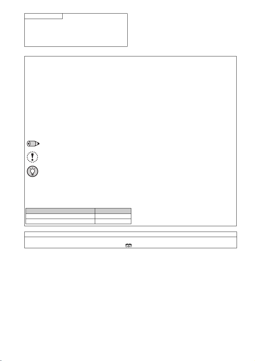
<Mark>
REMARKS: Additional helpful contents and relations with other functions are written.
Note: Contents requiring caution or cases when set functions are not activated are written.
POINT: Useful contents and points are written.
<Notes on descriptions in this Instruction Manual>
Connection diagrams in this Instruction Manual suppose that the control logic of the input terminal is the sink logic, unless
otherwise specified. (For the control logic, refer to page 1.)
<Related manuals>
The manuals related to this product are shown below.
Harmonic suppression guideline (when inverters are used in Japan)
All models of general-purpose inverters used by specific consumers are covered by "Harmonic suppression guideline for consumers who
receive high voltage or special high voltage". (For further details, refer to Chapter 3 of the FR-E700 Instruction Manual (Applied).)
A-3
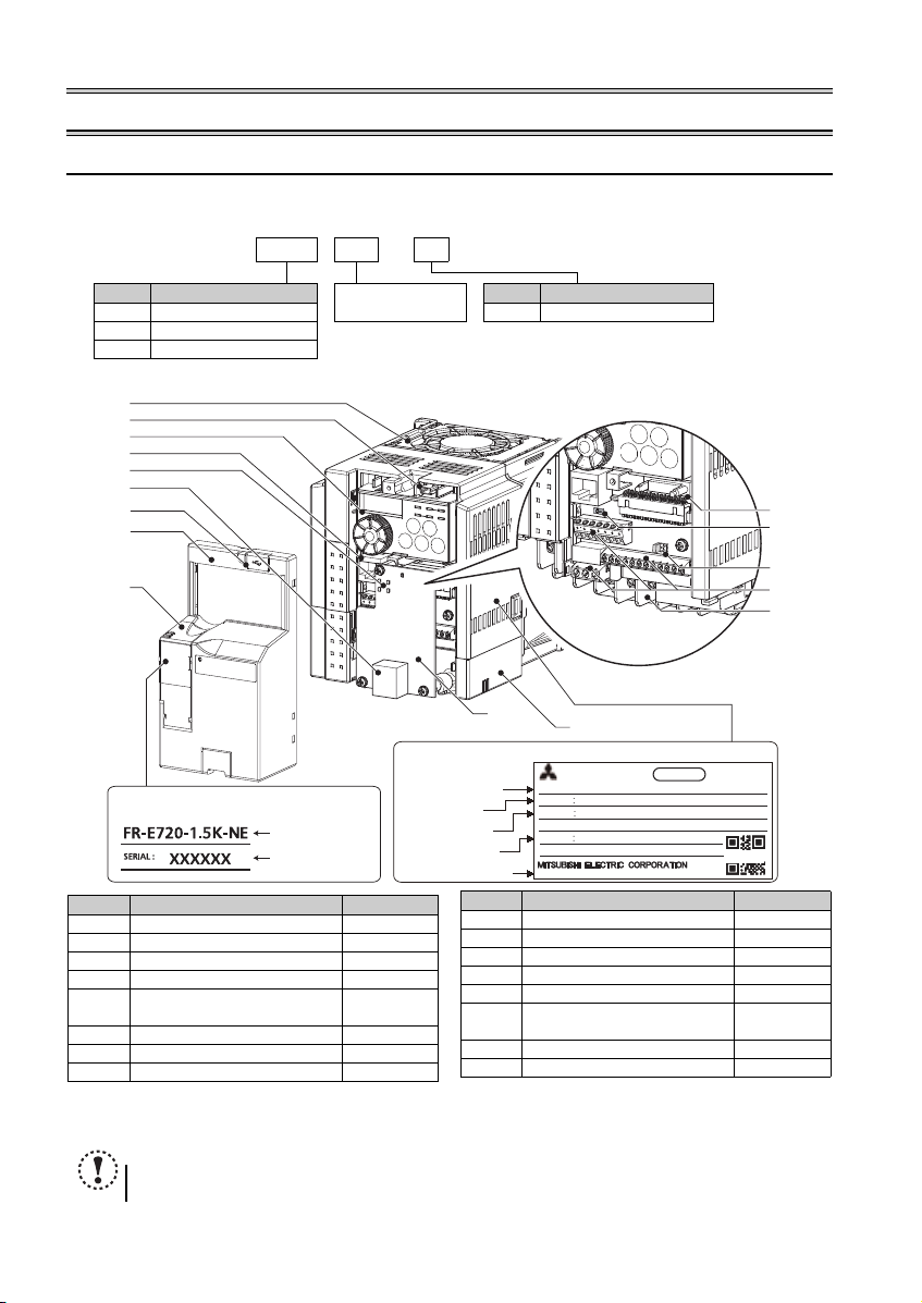
Product checking and parts identification
Inverter model
Serial number
Capacity plate
Input rating
Output rating
Serial number
Country of origin
Rating plate
Inverter model
ᴾ
MODEL FR-E720-1.5K-NE
INPUT XXXXX
OUTPUT
XXXXX
SERIAL
MADE IN JAPAN
ᾔᾛᾔᾒᾣᾡᾘᾒᾔᾛᾔᾒᾣᾡᾘᾒ
ᾜᾘᾣᾢᾤᾑᾘᾢᾗᾘ
ᾜᾘᾣᾢᾤᾑᾘᾢᾗᾘ
DATE : XXXX-XX
PASS ED
INVERTER
SAMPLE
(a)
(b)
(c)
(d)
(e)
(f)
(g)
(h)
(i)
(j)
(k)
(l)
(m)
(n)
(o)
(p)
View with the Ethernet board and
the wiring cover removed
Symbol Name Refer to Page
(a) Cooling fan
(b) USB connector (mini-B connector) 9
(c) Operation panel 3
(d) PU connector 9
(e)
LED indicator for communication
status
(f) Ethernet communication connector 17
(g) USB connector cover
(h) Front cover
(i) PU connector co ver 18
(j) Etherne t board 17
(k) Combed shaped wiring cover
(l) Ethernet bo ard connector 17
(m) Voltage/current input switch 9
(n)
Control logic switchover jumper
connector
(o) Control circuit terminal block 10
(p) Main circuit terminal block 10
Symbol Name Refer to Page
1 OUTLINE
1.1 Product checking and parts identification
Unpack the inverter and check the capacity plate on the front cover and the rating plate on the inverter side face to ensure that
the product agrees with your order and the inverter is intact.
Inverter model
FR - E720 - 1.5 K - NE
Symbol Voltage Class
E720 Three-phase 200V class NE Ethernet communication
E740 Three-phase 400V class
E720S Single-phase 200V class
Component names (FR-E720-1.5K-NE)
Represents the
inverter capacity [kW]
Symbol Function
Refer to the FR-E700 Instruction Manual (Applied).
Refer to the FR-E700-NE Ethernet Function Manual.
The jumper connector is set in the sink logic (SINK) position when shipped from the factory.
NOTE
All the switches (SW1 to SW3) on the Ethernet board are for manufacturer setting. Do not change the initial setting
1
(OFF).

1
Accessory
Capacity Quantity
FR-E720-1.5K to 3.7K, FR-E740-1.5K to 3.7K, FR-E720S-0.75K to 2.2K 1
FR-E720-5.5K to 15K, FR-E740-5.5K to 15K 2
· Fan cover fixing screws (M3 35mm)
These screws are necessary for
compliance with the EU Directive
(Refer to page 53)
REMARKS
For how to find the SERIAL number, refer to page 57.
Product checking and parts identification
2
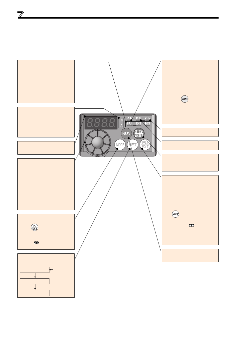
Operation panel
Operation mode indicator
PU: Lit to indicate PU operation mode.
EXT:
Lit to indicate External operation mod e.
(Lit at power-ON at initial setting.)
NET: Lit to indicate Network operation
mode.
PU, EXT: Lit to indicate External/PU
combined operation mode 1, 2.
These turn OFF when command source
is not on operation panel.
Unit indicator
Hz: Lit to indicate frequency.
(Blinks when the set frequency monit or
is displayed.)
A: Lit to indicate current.
(Both "Hz" and "A" turn OFF when other
than the above is displayed.)
Monitor (4-digit LED)
Shows the frequency, parameter number,
etc.
Setting dial
(Setting dial: Mitsubishi Electric inverter
dial)
Used to change the frequency setting and
parameter settings.
Press to display the following.
Displays the set frequency in the
monitor mode
Present set value is displayed during
calibration
Displays the order in the faults history
mode
Mode switchover
Used to change each setting mode.
Pressing simultaneously changes
the operation mode.
Pressing for a while (2s) can lock
operation. ( Refer to the Instruction
Manual (Applied))
Determination of each setting
If pressed during operation, monitor
changes as below:
Operating status indicator
Lit or blink during inverter operation.
* Lit: When the forward rotation operation
is being performed.
Slow blinking (1.4s cycle):
When the reverse operation is being
performed.
Fast blinking (0.2s cycle):
When was pressed or the
start command was given, but the
operation cannot be made.
When the frequency command is less
than the starting frequency.
When the MRS signal is input.
Parameter setting mode
Lit to indicate parame ter setting mode.
Monitor indicator
Lit to indicate monitoring mode.
Stop operation
Used to stop Run command.
Fault can be reset when protective
function is activated (fault).
Operation mode switchover
Used to switch between the PU and
External operation mode.
When using the External operation mode
(operation using a separately connected
frequency setting potentiometer and start
signal), press this key to light up the EXT
indication.
(Press simultaneously (0.5s) or
change Pr. 79 setting to change to
combined mode .) ( Refer to the
Instruction Manual (Applied))
PU: PU operation mode
EXT: External operation mode
Cancels PU stop also.
Start command
The rotation direction can be selected by
setting Pr. 40.
1.2 Operation panel
1.2.1 Names and functions of the operation panel
The operation panel cannot be removed from the inverter.
Running frequency
Output current
Output voltage
3
1
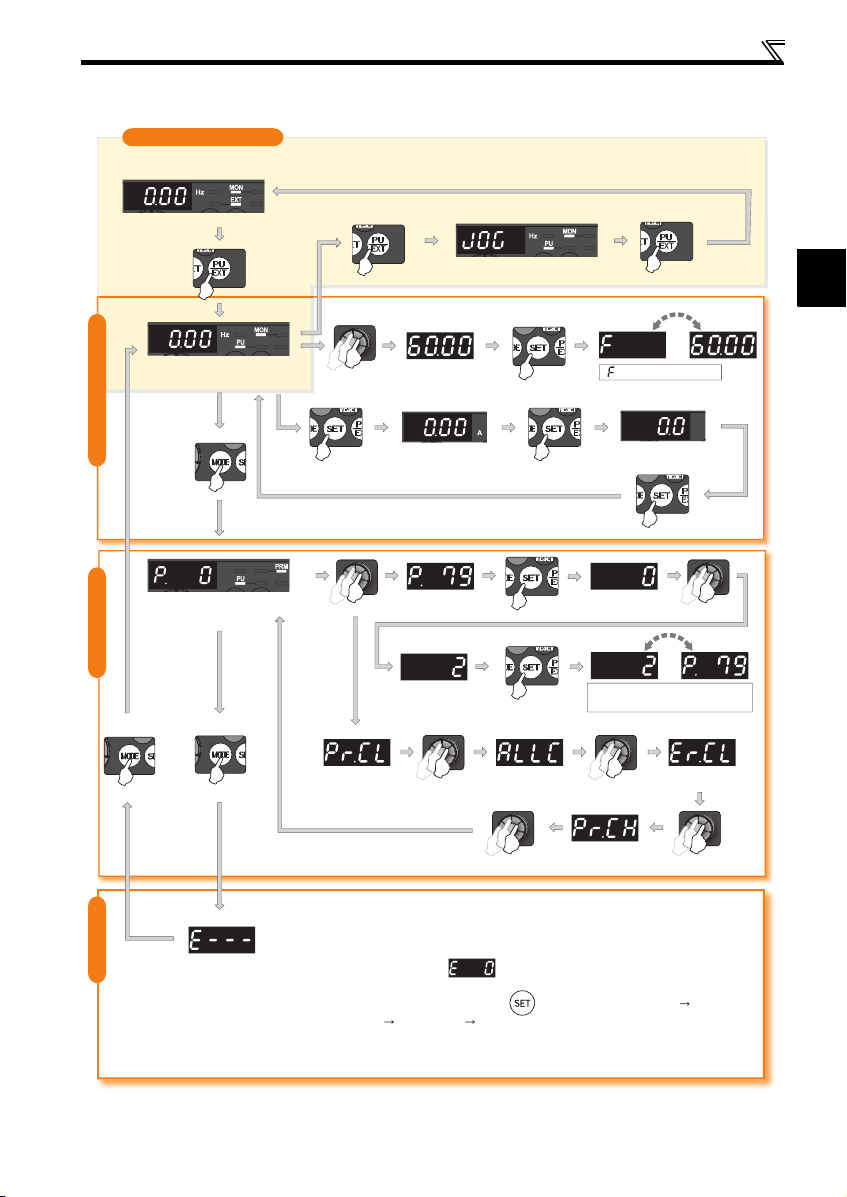
1.2.2 Basic operation (factory setting)
(Refer to page 42)
Operation mode switchover
At power-ON (External operation mode)
Operation panel
PU Jog operation mode
(Example)
PU operation mode
(output frequency monitor)
Parameter setting mode
Value change
Output current monitor
STOP
and frequency blink.
Frequency setting has been
written and completed!!
Output voltage monitor
Display the
present setting
(Example)
Parameter settingFaults history Monitor/frequency setting
Value change
Parameter clear All parameter
clear
Parameter and a setting value
blink alternately.
Parameter write is completed!!
Faults history clear
Initial value
change list
[Operation for displaying faults history]
Past eight faults can be displayed.
(The latest fault is ended by ".".)
When no fault history exists, is displayed.
While a fault is displayed:
The display shifts as follows by pressing : Output frequency at the fault
Output current Output voltage Energization time.
(After Energization time, it goes back to a fault display.)
Pressing the setting dial shows the fault history number.
4
Operation panel
REMARKS
is displayed...Why?
appears ....Write disable error
appears ....Write error during operation
appears ....Calibration error
appears .... Mode designation error
For details, refer to the FR-E700 Instruction
Manual (Applied).
The number of digits displayed on the oper ation
panel is four. Only the upper four digits of values can
be displayed and set. If the values to be displayed
have five digits or more including decimal places, the
fifth or later numerals cannot be displayed nor set.
(Example) For Pr. 1
When 60Hz is set, 60.00 is displayed.
When 120Hz is set, 120.0 is displayed and second
decimal place is not displayed nor set.
REMARKS
are displayed alternately ...
Why?
The inverter is not in the PU operation mode.
PU connector or USB connector is used.
1. Press . [PU] is lit and the monit or (4-digit LED)
displays "1". (When Pr. 79 = "0" (initial value))
2. Carry out operation from step 5 again.
Stop the inverter. Parameter clear is unavailable
when the inverter is running, and w ill cause the write
disable error.
and
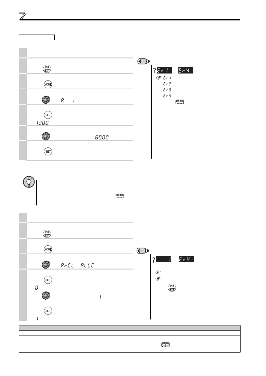
1.2.3 Changing the parameter setting value
Operation example Change the Pr. 1 Maximum frequency setting.
Screen at power-ON
1.
The monitor display appears.
Operation
Operation mode change
2.
Press to choose the PU op eration mode. PU indicator is lit.
Parameter setting mode
3.
Press to choose the parameter setting mode.
Selecting the parameter number
4.
Turn until " " (Pr. 1) appears.
Reading the setting value
5.
Press to read the pres ent set value.
" "(120.0Hz (initial value)) appears.
Changing the setting value
6.
Turn to change the set value to " " (60.00Hz).
Setting the parameter
7.
Press to set.
The parameter number and the setting value blink alternately.
1.2.4 Parameter clear/all parameter clear
POINT
Set "1" in Pr.CL Parameter clear or ALLC all parameter clear to initialize parameters. (Parameters are not cleared
when "1" is set in Pr. 77 Parameter write selection.)
Refer to the extended parameter list of the FR-E700 Instruction Manual (Applied) for parameters cleared
with this operation.
Screen at power-ON
1.
The monitor display appears.
Operation mode change
2.
Press to choose the PU op eration mode. PU indicator is lit.
Parameter setting mode
3.
Press to choose the parameter setting mode.
Selecting Parameter Clear (All Parameter Clear)
4.
Turn until " " (" ") appears
Selecting the setting value
Press to read the pres ent set value.
5.
" "(initial value) appears.
Turn to change it to the set value " ".
Press to set.
6.
Setting Description
5
Press to set.
" " and Pr. CL (ALLC) indication s blink alternately.
0 Clear is not executed.
Sets parameters back to the initial values. (Parameter clear sets back all parameters except calibration parameters, terminal
1
function selection parameters to the initial va lues.) Refer to the parameter list of the FR-E700 Instruction Manual (Appl ied) for
availability of parameter clear and a ll parameter clear.
Operation
to
2
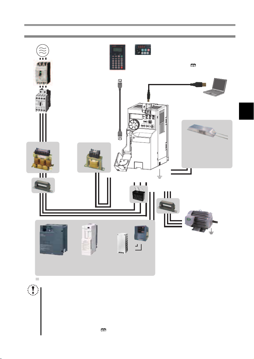
2 INSTALLATION AND WIRING
(Refer to page 48)
(Refer to page 7)
(Refer to page 7)
( Refer to Chapter 4
of the FR-E700 Instruction
Manual (Applied))
Brake resistor
(FR-ABR, MRS type, MYS type)
Braking capability can be i mproved. (0.4K
or higher)
Always install a thermal relay when using
a brake resistor whose capacity is 11K or
higher.
(Refer to page 19)
AC power supply
Use within the permissible power supply
specifications of the inverter. To ensure
safety, use a molded case circuit breaker,
AC reactor (FR-HAL)
earth leakage circuit breaker or magnetic
contactor to switch power ON/OFF.
Molded case circuit breaker (MCCB)
or earth leakage circuit breaker
(ELB), fuse
The breaker must be selected carefully
since an in-rush current flows in the
inverter at power ON.
Magnetic contactor (MC)
Install the magnetic contactor to ensure
safety. Do not use this magnetic contactor
to start and stop the inverter. Doing so will
cause the inverter life to be shorten.
Reactor (FR-HAL, FR-HEL option)
Reactors (option) must be used when power
harmonics measures are taken, the power
factor is to be improved or the inverter is
installed near a large power supply system
(500kVA or more). The inverter may be
damaged if you do not use reactors. Select
the reactor according to the model. Remove
the jumpers across terminals P/+ and P1 to
connect the DC reactor.
DC reactor (FR-HEL) *
Parameter unit
Enclosure surface operation panel
(FR-PA07)
By connecting the connection cable
(FR-CB2) to the PU connector, operation
can be performed from FR-PU07, FR-PA07.
(FR-PU07)
P/+
Noise filter (ferrite core) *
(FR-BSF01, FR-BLF)
* Filterpack (FR-BFP2), which contains DC reactor and EMC filter in one package, is also available.
Install a noise filter (ferrite core)
to reduce the electromagnetic
noise generated from the
inverter. Effective in the range
from about 1MHz to 10MHz.
When more wires are passed
through, a more effective result
can be obtained. A wire should
be wound four turns or more.
High power factor
converter (FR-HC2)
Power supply harmonics
can be greatly suppressed.
: Install this as required.
NOTE
The life of the inverter is influenced by surrounding air temperature. The surrounding air temperature should be as low as
possible within the permissible range. This must be noted especially when the inverter is installed in an enclosure. (Refer
to page 8)
Wrong wiring might lead to damage of the inverter. The control signal lines must be kept fully away from the main circuit
to protect them from no ise. (Refer to page 9)
Do not install a power factor correction capacitor, surge suppressor or capacitor type filter on the inverter output side.
This will cause the invert er to trip or the capacitor and surge suppressor to be damaged. If a ny of the above devices are
connected, immediatel y remove them.
Electromagnetic wave interference
The input/output (main circuit) of the inverter includes high frequen cy components, which may interfere with t he
communication devices (such as AM radios) used near the inverter. In this case, install options among the capacitor type
EMC filter FR-BIF (for use in the in put side only), the ferrite core type E MC filter FR-BSF01/FR-BLF, Filterpack, and EMC
filter to minimize the interferenc e. ( Refer to Chapter 3 of the FR-E700 Instruction Manual (Applied)).
Refer to the instruction manual of each option and peripheral devices for details of peripheral devices.
Power regeneration
common converter
(FR-CV)
Great braking capability
is obtained.
Inverter (FR-E700-NE)
P1
P/+
Noise filter
(capacitor) *
(FR-BIF)
Reduces the
radio noise.
Brake unit
(FR-BU2)
Resistor unit (FR-BR)
Discharging resistor (GZG, GRZG)
The regenerative braking capability
of the inverter can be exhibited fully.
R/L1 S/L2T/L3
PR
P/+
P/+
PR
PR
Earth (Ground)
UW
V
P/+
N/-
Devices connected to the output
Do not install a power factor correction capacitor,
surge suppressor or capacitor type filter on the output
side of the inverter. When installing a molded case
circuit breaker on the output side of the inverter,
contact each manufacturer for selection of the
molded case circuit breaker.
Earth (Ground)
To prevent an electric shock, always earth (ground)
the motor and inverter. For reduction of induction noise
from the power line of the inverter, it is recommended
to wire the earthing cable by returning it to the earth
(ground) terminal of the inverter.
USB connector
A personal computer and
an inverter can be connected
with a USB (Ver1. 1) cable.
Noise filter (ferrite core)
(FR-BSF01, FR-BLF)
Install a noise filter (ferrite core)
to reduce the electromagnetic
noise generated from the inverter.
Effective in the range from about
1MHz to 10MHz. A wire should be
wound four turns at a maximum.
Motor
Earth (Ground)
6
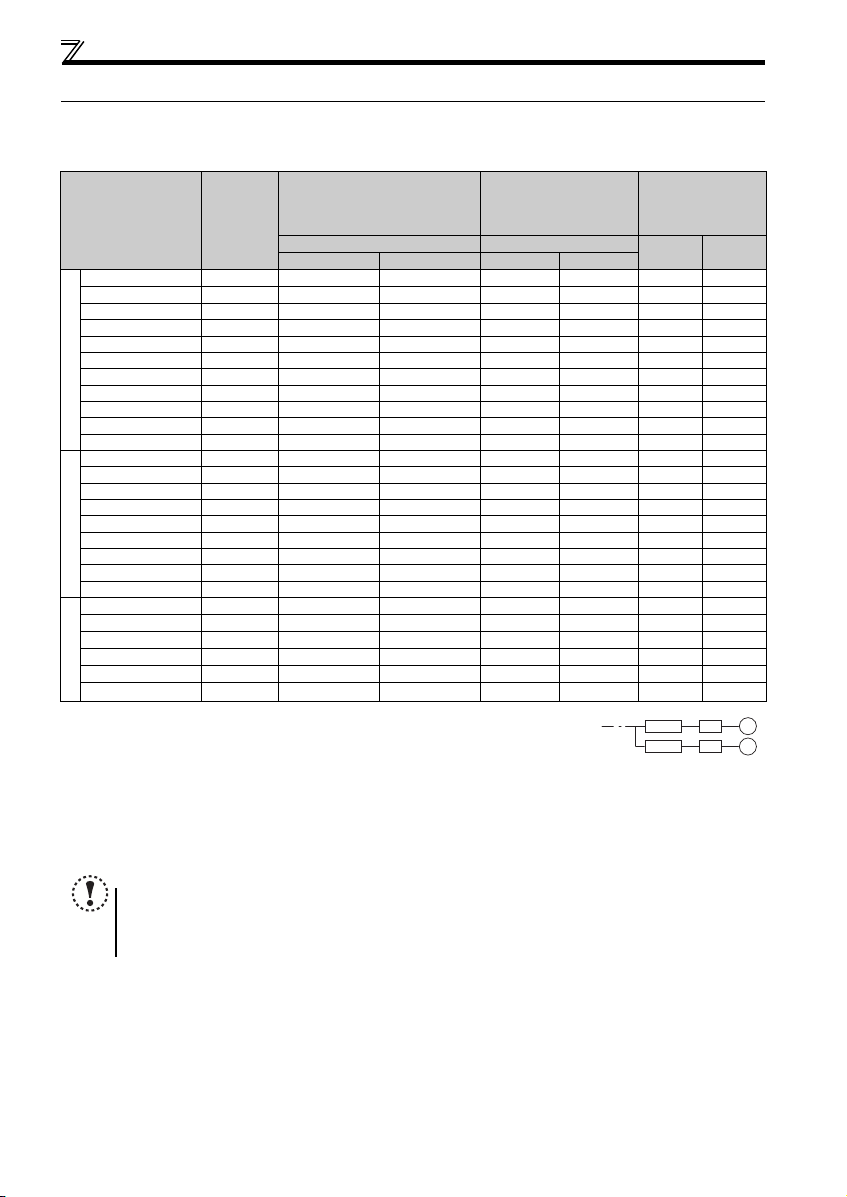
Peripheral devices
2.1 Peripheral devices
Check the inverter model of the inverter you purchased. Appropriate peripheral devices must be selected according to the capacity.
Refer to the following list and prepare appropriate peripheral devices.
Molded Case Circuit Breaker
(MCCB)
Applicable Inverter
Model
Motor
Output
(kW)
or Earth Leakage Circuit Breaker
(ELB)
Reactor connection Reactor connection
(NF, NV type)
without with without with
FR-E720-0.1K 0.1 5A 5A S-T10 S-T10 0.4K
FR-E720-0.2K 0.2 5A 5A S-T10 S-T10
FR-E720-0.4K 0.4 5A 5A S-T10 S-T10 0.4K 0.4K
FR-E720-0.75K 0.75 10A 10A S-T10 S-T10 0.75K 0.75K
FR-E720-1.5K 1.5 15A 15A S-T10 S-T10 1.5 K 1. 5K
FR-E720-2.2K 2.2 20A 15A S-T10 S-T10 2.2 K 2. 2K
FR-E720-3.7K 3.7 30A 30A S-T21 S-T10 3.7 K 3. 7K
FR-E720-5.5K 5.5 50A 40A S-T35 S-T21 5.5 K 5. 5K
Three-Phase 200V
FR-E720-7.5K 7.5 60A 50A S-T35 S-T35 7.5 K 7. 5K
FR-E720-11K 11 75A 75A S-T35 S-T35 11K 11K
FR-E720-15K 15 125A 100A S-T50 S-T50 15K 15K
FR-E740-0.4K 0.4 5A 5A S-T10 S-T10 H0.4K H0.4K
FR-E740-0.75K 0.75 5A 5A S-T10 S-T10 H0.75K H0.75K
FR-E740-1.5K 1.5 10A 10A S-T10 S-T10 H1.5K H1.5K
FR-E740-2.2K 2.2 15A 10A S-T10 S-T10 H2.2K H2.2K
FR-E740-3.7K 3.7 20A 15A S-T10 S-T10 H3.7K H3.7K
FR-E740-5.5K 5.5 30A 20A S-T21 S-T12 H5.5K H5.5K
FR-E740-7.5K 7.5 30A 30A S-T21 S-T21 H7.5K H7.5K
Three-Phase 400V
FR-E740-11K 11 50A 40A S-T21 S-T21 H11K H11K
FR-E740-15K 15 60A 50A S-T35 S-T21 H15K H15K
FR-E720S-0.1K 0.1 5A 5A S-T10 S-T10
FR-E720S-0.2K 0.2 5A 5A S-T10 S-T10
FR-E720S-0.4K 0.4 10A 10A S-T10 S-T10
FR-E720S-0.75K 0.75 15A 10A S-T10 S-T10
FR-E720S-1.5K 1.5 20A 20A S-T10 S-T10
FR-E720S-2.2K 2.2 40A 30A S-T21 S-T10
Single-Phase 200V
Select an MCCB according to the power supply capacity.
Install one MCCB per inverter.
For the use in the United States or Canada, refer to page 56, and select an appropriate fuse or molded case circuit
breaker (MCCB).
Magnetic contactor is selected based on the AC-1 class. The electrical durability of magnetic contactor is 500,000 times. When the magnetic contactor is
used for emergency stop during motor driving, the electrical durability is 25 times.
When using the MC for emergency stop during motor driving or using on the motor side during commercial-power supply operation, select the MC with class
AC-3 rated current for the motor rated current.
The power factor may be slightly lower.
Magnetic Contactor (MC)
Reactor
FR-HAL FR-HEL
0.4K
0.4K
0.4K
0.4K
0.4K
0.4K
0.4K
0.75K
0.75 K
1.5K
1.5K
2.2K
2.2K
3.7K
3.7K
MCCB INV
MCCB INV
IM
IM
NOTE
When the inverter capacity is larger than the motor capacity, select an MCCB and a magnetic contactor according to
the inverter model and cable and reactor according to the motor output.
When the breaker on the inverter input side trips, check for the wiring fault (short circuit), damage to internal parts of
the inverter, etc. Identify the cause of the trip, then remove the cause and power ON the breaker.
7
2
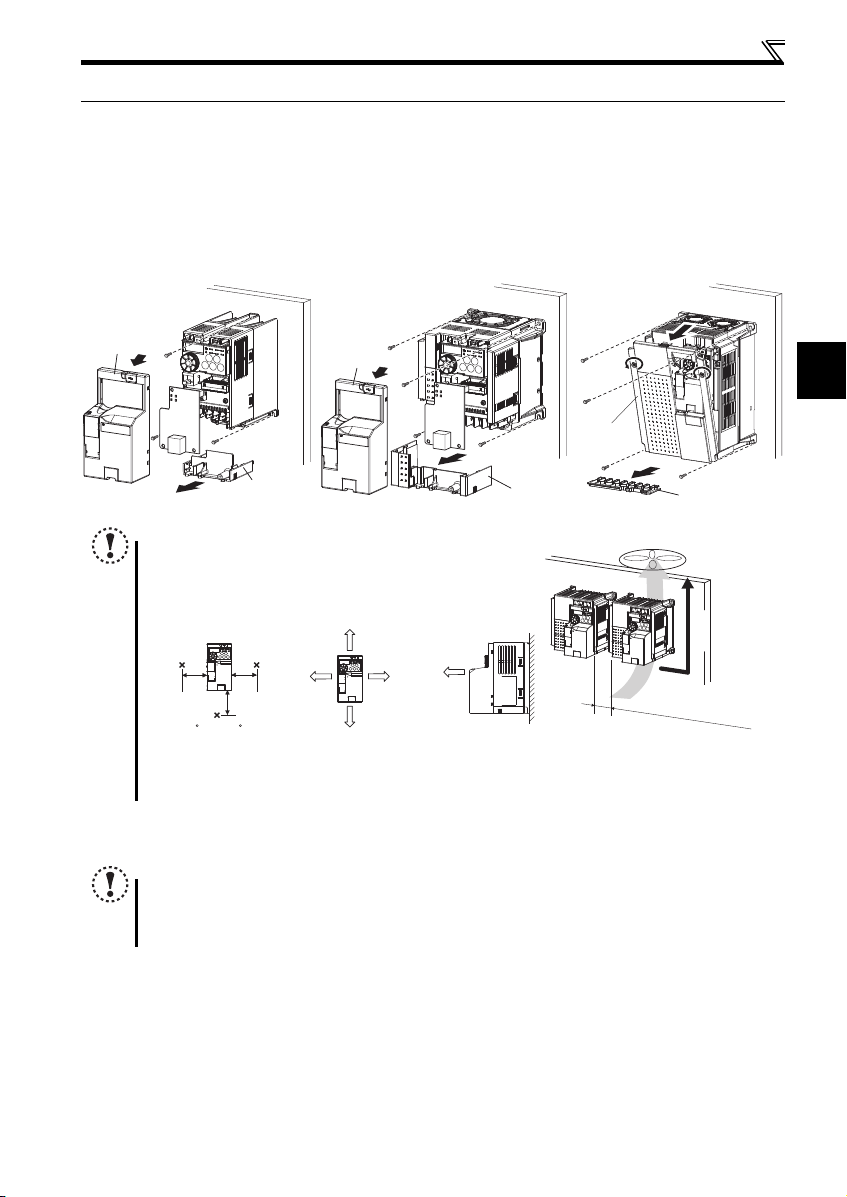
Installation of the inverter and instructions
Front cover
Wiring cover
Front cover
Wiring cover
FR-E720-0.1K to 0.75K
FR-E720S-0.1K to 0.4K
FR-E720-1.5K to 3.7K
FR-E740-0.4K to 7.5K
FR-E720S-0.75K or higher
Front cover 1
FR-E720-5.5K to 15K
FR-E740-11K, 15K
Wiring cover
Vertical
Refer to the clearances
shown on the left.
10cm or more
10cm or more
1cm or
more
1cm or
more
Measurement
position
Measurement
position
5cm
5cm
5cm
-10 C to +50 C
(non-freezing)
1cm or
more
, ,
2.2 Installation of the inverter and instructions
(1) Installation of the inverter
Enclosure surface mounting
Before installation, remove the front cover and the wiring cover. (Remove the covers in the directions of the arrows.)
For the FR-E720-3.7K or lower, FR-E740-7.5K or lower, or FR-E720S-2.2K or lower inverter, additionally remove the Ethernet
board. (Refer to page 17.)
Note
When encasing multiple inv erters, install them in parallel as a co oling
measure.
Install the inverter vertically.
For heat dissipation and maintenance, allow minimum clearances
around the inverter as shown in the following figures.
(2) Environment
Before installation, check that the environment meets the specifications on page 49.
Take 5cm or more clearances for 5.5K or higher.
When using the inverters at the surrounding air temperature of 40C or less, the inverters can be installed without any clearance between
them (0cm clearance).
Note
Install the inverter on a strong surface securely and vertically with bolts.
Leave enough clearances and take cooling measures.
Avoid places where the inverter is subjected to direct sunlight, high temperature and high humidity.
Install the inverter on a nonf lammable wall surface.
8
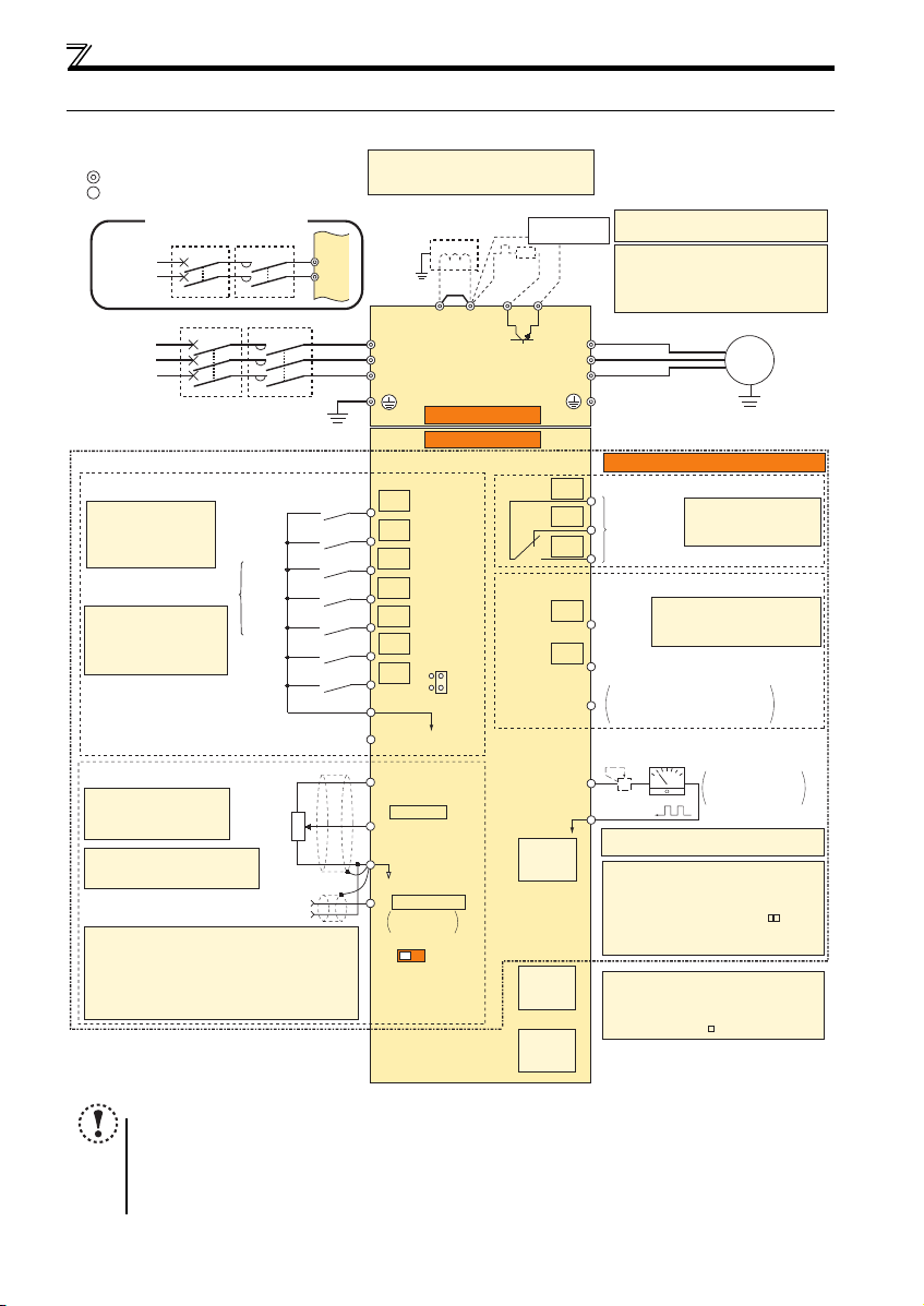
Wiring
Earth
(Ground)
Motor
IM
Earth (Ground)
Three-phase
AC power
supply
MCCB MC
R/L1
P1 P/+
PR
N/-
S/L2
T/L3
U
V
W
Earth
(Ground)
*7 Brake resistor (FR-ABR, MRS, MYS type)
Install a thermal relay to prevent an
overheat and burnout of the brake resistor.
(The brake resistor cannot be connected
to the 0.1K and 0.2K.)
*6 A brake transistor is not built-in to the
0.1K and 0.2K.
Forward
rotation start
Reverse
rotation start
Middle
speed
High
speed
Low
speed
Output
stop
Reset
Control input signals (No voltage input allowed)
Contact input common
24VDC power supply
(Common for external power supply transistor)
STR
STF
RH
RM
RL
MRS
SD
PC
Relay output
Running
Frequency detection
Open collector output
Open collector output common
Sink/source common
FU
RUN
SE
A
B
C
FM
SD
Indicator
(Frequency meter, etc.)
+
-
Moving-coil type
1mA full-scale
Calibration resistor
Frequency setting signals (Analog)
2 0 to 5VDC
10(+5V)
2
3
1
4 4 to 20mADC
Frequency
setting
potentiometer
1/2W1kΩ
(+)
(-)
5(Analog common)
*4
*3 Terminal input specifications
can be changed by analog
input specifications
switchover (Pr. 73).
*2 When using terminals PC
and SD as a 24VDC
power supply, take care
not to short across
terminals PC and SD.
PU
connector
USB
connector
Control circuit terminal
Main circuit terminal
Sink logic
Jumper
*1
*7
*6
*2
*3
*5
*8
Terminal functions vary
with the input terminal
assignment (Pr. 178 to
Pr. 184)
Multi-speed selection
Terminal functions vary with
the output terminal assignment
(Pr. 190 and Pr. 191)
Terminal functions vary
by Pr. 192 A,B,C terminal
function selection
SINK
SOURCE
IV
*5
0 to 5VDC
(0 to 10VDC)
0 to 10VDC
Voltage/current
input switch
Main circuit
Control circuit
Standard control terminal block
R
RES
Relay output
(Fault output)
Brake unit
(Option)
Single-phase
AC power
supply
MCCB MC
R/L1
S/L2
Single-phase power input
*5 Terminal input specifications can be changed by analog
input specifications switchover (Pr. 267). Set the
voltage/current input switch in the "V" position to select
voltage input (0 to 5V/0 to10V) and "I" (initial value) to
select current input (4 to 20mA).
To use terminal 4 (initial setting is current input), set "4"
in any of Pr.178 to Pr.184 (input terminal function selection)
to assign the function, and turn ON AU signal.
*1. DC reactor (FR-HEL)
When connecting a DC reactor, remove the
jumper across P1-P/+.
*9
*10
*9 Operation and parameter setting can be
done from the parameter unit (FR-PU07)
and the enclosure surface operation panel
(FR-PA07).
(Use the option cable (FR-CB2 ).)
RS-485 communication can be utilized from
a personal computer and other devices.
*8 It is not necessary when calibrating the
indicator from the operation panel.
Ethernet
connector
Terminal 4 input
(Current input)
*4 It is recommended to use 2W1kΩ
when the frequency setting signal
is changed frequently.
*10 A personal computer and an inverter can be
connected with a USB (Ver1.1) cable.
You can perform parameter setting and
monitoring with the FR Configurator2
(SW1DND-FRC2- ).
2.3 Wiring
2.3.1 Terminal connection diagram
NOTE
To prevent a malfunction caused by noise, separate the signal cables more than 10cm from the power cables. Also
separate the main circuit wire of the input side and the output side.
After wiring, wire offcuts must not be left in the inverter.
Wire offcuts can cause an alarm, failure or malfunction. Always keep the inverter clean. When drilling mounting holes
in an enclosure etc., take ca re not to allow chips and oth er foreign matter to e nter the inverter.
The output of the single-phase power input model is three-phase 200V.
9
2
Wiring
Voltage input
Current input
(initial status)
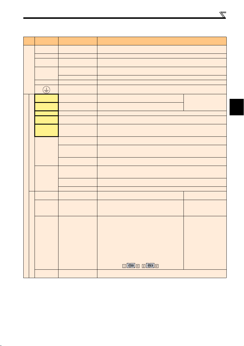
2.3.2 Terminal specifications
Terminal
Typ e
Symbol
R/L1, S/L2,
T/L3 *
U, V, W Inverter output
P/+, PR Brake resistor connection
P/+, N/-
Main circuit
P/+, P1 DC reactor connection
STF Forward rotation start
STR Reverse rotation start
RH, RM, RL Multi-speed selection
MRS Outp ut stop
RES Reset
SD
Contact input
PC
10
Control circuit/input signal
2
4
Frequency setting
Terminal Name Description
AC power input
Brake unit connection
DC power input
Earth (Ground)
Contact input common
(sink) (initial setting)
External transistor
common (source)
24VDC power supply
common
External transistor
common
(sink) (initial setting)
Contact input common
(source)
24VDC power supply
Frequency setting power
supply
Frequency setting
(voltage)
Frequency setting
(current)
Connect to the commercial power supply. Keep these terminals open when using the high
power factor converter (FR-HC) or power reg eneration common converter (FR-CV).
Connect a three-phase squirrel-cage motor.
Connect a brake resistor (MRS type, MYS type, FR-ABR) across terminals P/+ and PR.
(The brake resistor cannot be connect ed to the 0.1K or 0.2K)
Connect the brake unit (FR-BU2), power regeneration common conve rter (FR-CV) or high
power factor converter (FR-HC).
Connect the plus side of the power supply to terminal P/+ and minus side to terminal N/-.
Remove the jumper across terminals P/+ and P1 and connect a DC reactor.
For earthing (grounding) the inverter chassis. Must be earthed (grounded).
Turn ON the STF signal to start forward rotation and tu rn it OFF
to stop.
Turn ON the STR signal to start reverse rotation and turn it OFF
to stop.
Multi-speed can be selected according to the combination of RH, RM and RL signals.
Turn ON the MRS signal (20ms or more) to stop the inverter output.
Use to shut off the inverter output when stopping the motor by electromagnetic brake.
Used to reset alarm output provided when protective circuit is activated. Turn ON the RES
signal for more than 0.1s, then turn it OFF. Initial setting is for reset always. By setting Pr. 75,
reset can be set to enabled only at fault occurrence. Recover about 1s after reset is cancelled.
Common terminal for contact input terminal (sink logic) and terminal FM.
Connect this terminal to the power supply common terminal of a transistor output (open
collector output) device, such as a programmable controller, in the source logic to avoid
malfunction by undesirable current.
Common output terminal for 24VDC 0.1A power supply (PC terminal).
Isolated from terminals 5 and SE.
Connect this terminal to the power supply common terminal of a transistor output (open
collector output) device, such as a programmable controller, in the sink logic to avoid
malfunction by undesirable current.
Common terminal for contact input terminal (source logic).
Can be used as 24VDC 0.1A power supply.
Used as power supply when connecting potentiometer for
frequency setting (speed setting) from outside of the inverter.
Inputting 0 to 5VDC (or 0 to 10V) provides the maximum outp ut
frequency at 5V (10V) and makes input and output
proportional. Use Pr. 73 to switch between input 0 to 5VDC
(initial setting) and 0 to 10VDC input.
Inputting 0 to 20mADC (or 0 to 5V / 0 to 10V) provides the
maximum output frequency at 20mA and makes input and
output proportional. This input signal is valid only wh en the AU
signal is ON (terminal 2 input is invalid). To use terminal 4
(initial setting is cur rent input), set "4" to a ny of Pr.178 to Pr.184
(input terminal function selection) , and turn AU signal ON. Use
Pr. 267 to switch among input 4 to 20mA (initial setting), 0 to
5VDC, and 0 to 10VDC. Set the voltage/current input switch in
the "V" position to select voltage input (0 to 5V/0 to 10V).
When the STF and STR
signals are turned ON
simultaneously, the stop
command is given.
5VDC
permissible load current 10mA
Input resistance 10k ± 1k
Permissible maximum voltage
20VDC
Voltage input:
Input resistance 10k ± 1k
Permissible maximum voltage
20VDC
Current input:
Input resistance 233 ± 5
Maximum permissible current
30mA.
5
Frequency setting
common
Common terminal for the frequency setting signals (terminals 2 and 4). Do not ear th (ground).
10
Wiring
r
Motor
Power supply
N/-
P/+
PR
IM
R/L1 S/L2 T/L3
Jumper
Terminal
Typ e
Control circuit/output signal
Symbol
A, B, C
Relay
RUN Inverter running
FU Frequency detection
Open collector
SE
FM For meter
Pulse
— Ethernet connector
Communication
— PU connector
— USB connector
Terminal Name Description
Relay output
(fault output)
Open collector
output common
1 changeover contact output indicates th at the inverter fault occurs.
Fault: discontinuity across B-C (continuity across A-C), Normal: continuity across B-C
(discontinuity across A-C) Contact capacity 230VAC 0.3A (power factor = 0.4) 30VDC 0.3A
Switched Low when the inverter output frequency is equal to or
higher than the starting frequency (initial value 0.5Hz ).
Switched High during stop or DC injection brake operation.
Switched Low when the inverter output frequency is equal to or
higher than the preset detected frequency and High when less
than the preset detected frequency.
Common terminal of terminal RUN and FU.
Used to output a selected monitored item (such as Output
frequency) among several monitored items. (Not output during
inverter reset.) The output signal is proportional to the
magnitude of the corresponding monitoring item.
Communication can be made via Ethernet.
· Category: 100BASE-TX/10BASE-T
· Data transmission speed: 100Mbps (100BASE-TX) / 10Mbps (10BASE-T)
· Transmission method: Baseband
· Maximum segment length: 100m between the hub and the inverte r
· Number of cascade connection stages: Up to 2 (100BASE-TX) / up to 4 (10BASE -T)
· Interface: RJ-45
· Number of interfaces available: 1
· IP version: IPv4
With the PU connector, RS-485 communication can be established.
· Conforming standard: EIA-485 (RS-485) · Transmission format: Multi-dr op link
· Communication speed: 4800 to 38400bps · Overall extension: 500m
Use the USB connector to communicate with a personal computer. Setting and monitoring of
the inverter is enabled using FR Configurator2.
· Interface: conforms to USB1.1 · Transmission Speed: 12Mbps
· Connector: USB mini B connector (receptacle mini B type)
Permissible load 24VDC
(Maximum 27VDC) 0.1A
(a voltage drop is 3.4V
maximum when the signal is
on)
Low is when the open
collector output transistor is
ON (conducts). High is when
the transistor is OFF (does
not conduct).
Permissible load current 1mA
1440 pulses/s at 60Hz
Note
Set Pr. 267 and a voltage/current input switch correctly, then input an analog signal in accordance with the setting.
Applying a voltage with voltage/curre nt input switch in "I" positio n (current input is selected ) or a current with switch
in "V" position (voltage input is selected) could cause component damage of the inverter or analog circuit of output
devices.
The inverter will be damaged if power is applied to the inverter output terminals (U, V, W). Never perform such wiring.
indicates that terminal functions can be selected using Pr. 178 to Pr. 184 and Pr. 190 to Pr. 192 (I/O terminal function
selection).
Terminal names and terminal functions are those of the factory set.
When connecting the DC power supply, be sure to connect the plus side of the power supply to terminal P/+ and
minus side to terminal N/-. Opposite polarity will damage the inverter.
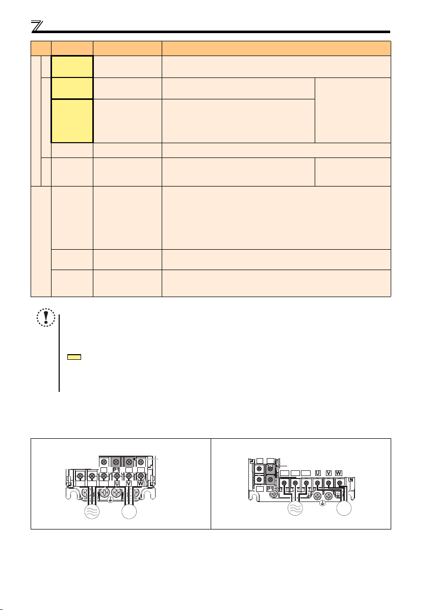
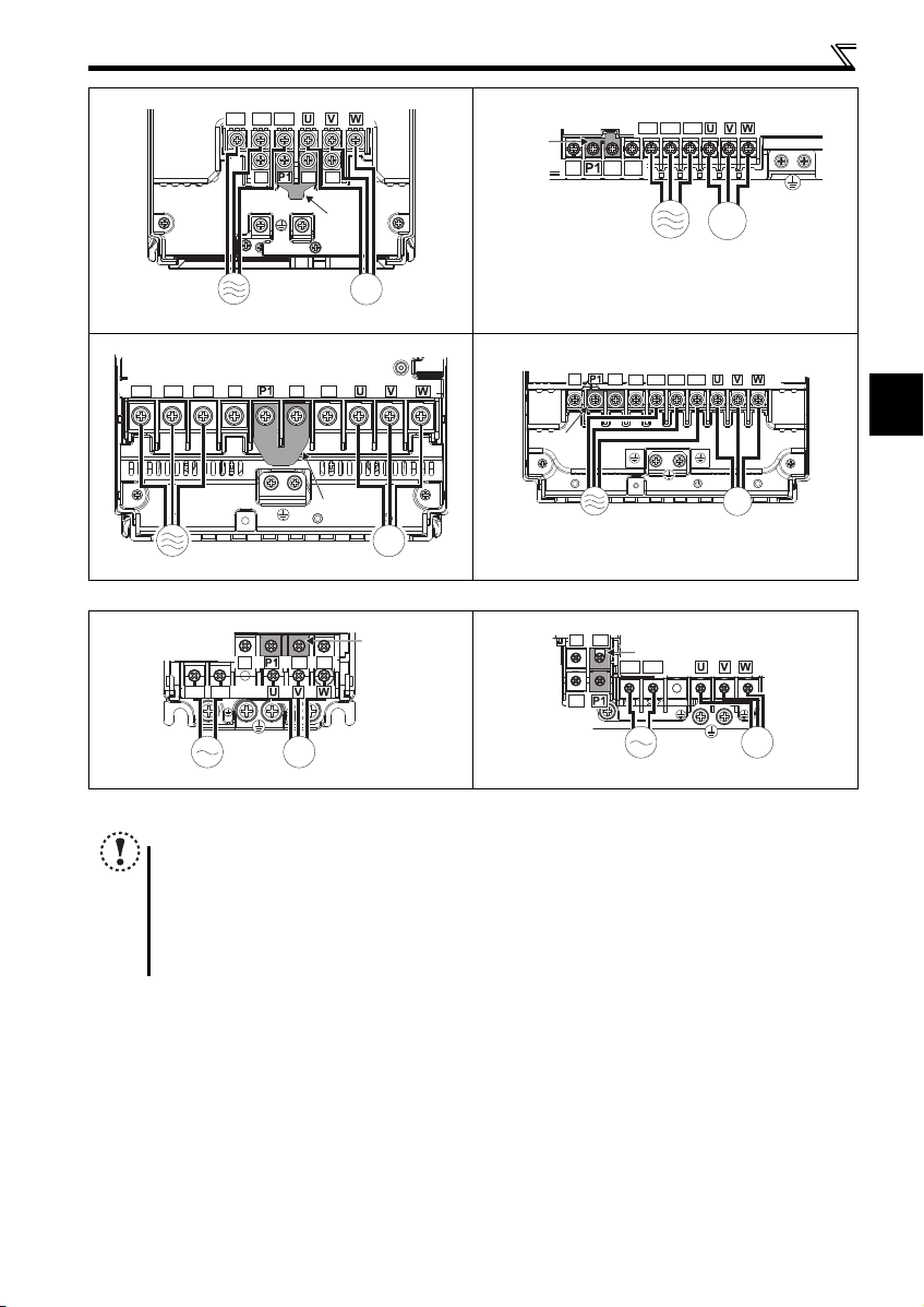
2.3.3 Terminal arrangement of the main circuit terminal, power supply and the motor wiring
Three-phase 200V/400V class
FR-E720-0.1K to 0.75K FR-E720-1.5K to 3.7K
Jumpe
N/-
P/+ PR
R/L1 S/L2 T/L3
FR-E740-0.4K to 3.7K
11
IM
MotorPower supply
2
Wiring
N/-
P/+
PR
R/L1 S/L2 T/L3
MotorPower supply
Jumper
IM
N/-
P/+
PR
R/L1 S/L2 T/L3
Jumper
MotorPower supply
IM
r
Motor
Power supply
N/-
P/+
PR
IM
R/L1 S/L2
Jumper
FR-E720-5.5K, 7.5K FR-E740-5.5K, 7.5K
R/L1 S/L2 T/L3
N/-
P/+
PR
Jumper
IM
Power supply
FR-E720-11K, 15K FR-E740-11K, 15K
Single-phase 200V class
FR-E720S-0.1K to 0.4K FR-E720S-0.75K to 2.2K
N/-
R/L1 S/L2
Motor
N/-
Jumper
Power supply
Jumpe
P/+ PR
P/+
R/L1 S/L2 T/L3
PR
IM
Motor
IM
MotorPower supply
NOTE
Before wiring cables to the main circuit terminals, remove the wiring cover. (For the FR-E720-3.7K or lower, FR-E740-
7.5K or lower, or FR-E720S-2.2K or lower inverter, additionally remo ve the Ethernet board.)
To remove the Ethernet board, refer to page 17. To remove the wiring cover, refer to page 8.
Make sure the power cables are connected to the R/L1, S/L2, and T/L3. (Phase need not be matched.) Never connect
the power cables to the U, V, and W of the inverter. Doing so will damage the inverter.
Connect the motor to U, V, and W. Turning ON the forward rotation switch (signal) at this time rotates the motor
counterclockwise when viewed from the load shaft.
12
Wiring
3 × wire resistance [mΩ/m] × wiring distance [m] × current [A]
1000
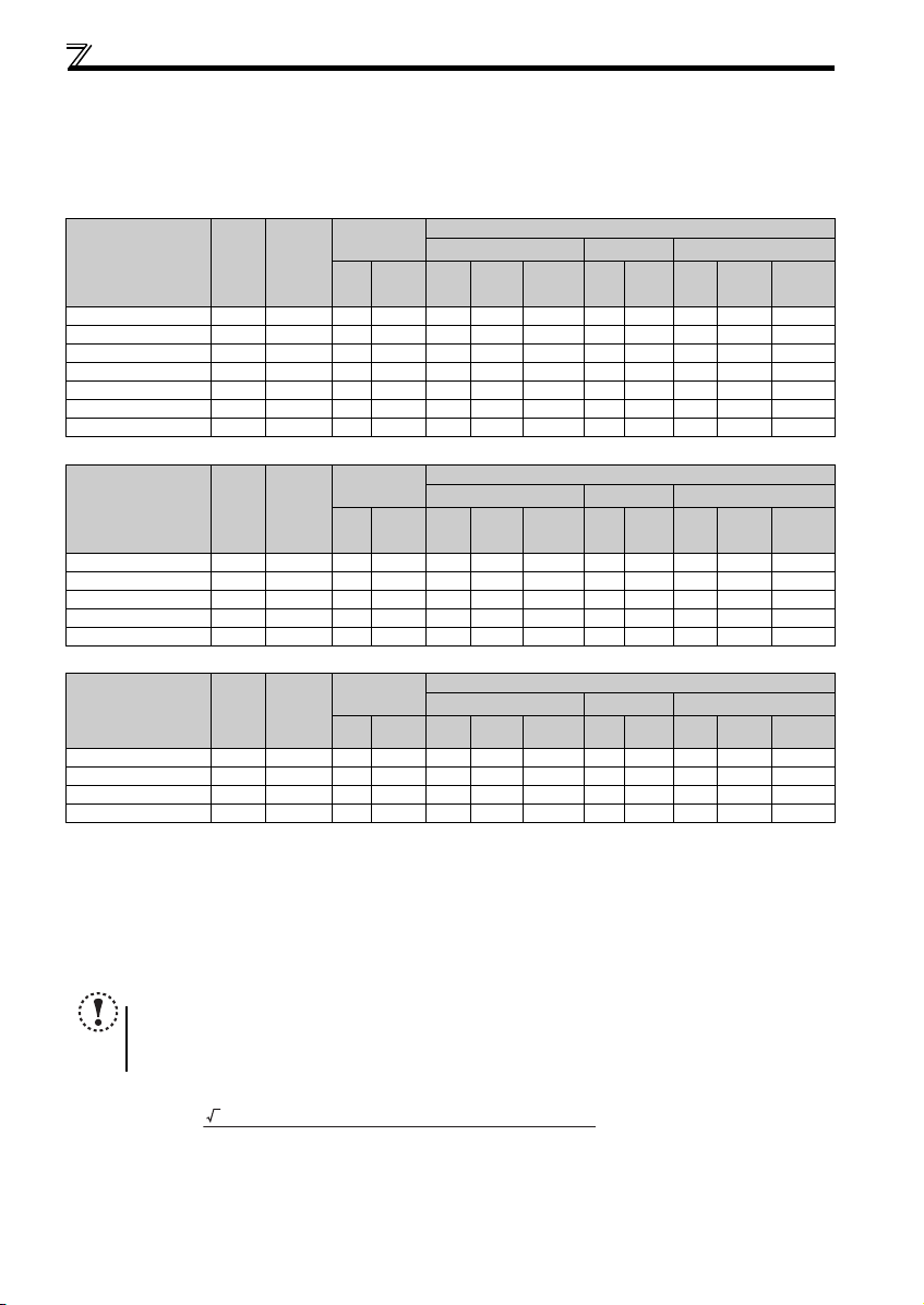
(1) Cable size and other specifications of the main circuit terminals and the earthing terminal
Select the recommended cable size to ensure that a voltage drop will be 2% at maximum.
If the wiring distance is long between the inverter and motor, a main circuit cable voltage drop will cause the motor torque to
decrease especially at the output of a low frequency.
The following table indicates a selection example for the wiring length of 20m.
Three-phase 200V class (when input power supply is 220V)
Crimp
Ter mi nal
Applicable Inverter
Model
FR-E720-0.1K to 0.75K M3.5 1.2 2-3.5 2-3.5 2 2 2 14 14 2.5 2.5 2.5
FR-E720-1.5K, 2.2K M4 1.5 2-4 2-4 2 2 2 14 1 4 2.5 2.5 2.5
FR-E720-3.7K M4 1.5 5.5-4 5.5 -4 3.5 3.5 3.5 12 12 4 4 4
FR-E720-5.5K M5 2.5 5.5-5 5.5 -5 5.5 5.5 5.5 10 10 6 6 6
FR-E720-7.5K M5 2.5 14-5 8-5 14 8 5.5 6 8 16 10 6
FR-E720-11K M5 2.5 14-5 14-5 14 14 8 6 6 16 16 16
FR-E720-15K M6(M5) 4.4 22-6 22-6 22 22 14 4 4 25 25 16
Screw
Size
Tightening
Torque
Ter min al
R/L1
·
m
N
S/L2
T/L3
HIV Cables, etc. (mm2)
R/L1
U, V, W
S/L2
T/L3
U, V, W
Earthing
Three-phase 400V class (when input power supply is 440V)
Crimp
N·m
Ter min al
R/L1
S/L2
T/L3
HIV Cables, etc. (mm2)
R/L1
U, V, W
S/L2
T/L3
U, V, W
Earthing
Ter mi nal
Applicable Inverter
Model
FR-E740-0.4K to 3.7K M4 1.5 2-4 2-4 2 2 2 14 14 2.5 2.5 2.5
FR-E740-5.5K M4 1 .5 5.5-4 2-4 3.5 2 3.5 12 14 4 2.5 4
FR-E740-7.5K M4 1 .5 5.5-4 5.5-4 3.5 3.5 3.5 12 1 2 4 4 4
FR-E740-11K M4 1.5 5.5-4 5.5-4 5.5 5.5 5.5 10 10 6 6 10
FR-E740-15K M5 2.5 8-5 8-5 8 8 5.5 8 8 10 10 10
Screw
Size
Tightening
Torque
Single-phase 200V class (when input power supply is 220V)
Ter mi nal
Applicable Inverter
Model
FR-E720S-0.1K to 0.4K M3.5 1.2 2-3.5 2-3.5 2 2 2 14 14 2.5 2.5 2.5
FR-E720S-0.75K M4 1.5 2-4 2-4 2 2 2 14 14 2.5 2.5 2.5
FR-E720S-1.5K M4 1.5 2-4 2-4 2 2 2 14 14 2.5 2.5 2 .5
FR-E720S-2.2K M4 1.5 5.5-4 2-4 3.5 2 2 12 14 4 2.5 2.5
The cable size is that of the cable (HIV cable (600V class 2 vinyl-insulated cable) etc.) with continuous m aximum permissible temperatur e of 75°C. Assumes
that the surrounding air temperatur e is 50°C or less and the wiring distance is 20m or less.
The recommended cable size is that of the cable (THHW cable) with continuous maximum permissible temperature of 75°C. Assumes that the surrounding air
temperature is 40°C or less and t he wiring distance is 20m or less. (For the use in t he United States or Canada, refer to
The recommended cable size is that of the cable (PVC cable) with continuou s maximum permissible temperatu re of 70°C. Assumes that the sur rounding air
temperature is 40°C or less and t he wiring distance is 20m or less. (Selection examp le for use mainly in Europe.)
The terminal screw size indicates the terminal size for R/L1, S/L2, T/L3, U, V, W, PR, P/+, N/-, P1 and a screw for earthing (grounding).
A screw for earthing (grounding) of the FR-E720-15K is indicated in ( ).
For single-phase power input, the terminal screw size indicates the size of terminal screw for R/L1, S/L2, U, V, W, PR, P/+, N/-, P1 and a screw for earthing
(grounding).
Screw
Size
Tightening
Torque
N·m
Ter min al
R/L1
S/L2
Crimp
U, V, W
HIV Cables, etc. (mm2)
R/L1
S/L2
U, V, W
Earthing
NOTE
Tighten the terminal screw to the specified torque. A screw that has been tighten too loosely can cause a short circuit
or malfunction. A screw that has been tighten too tightly can cause a short circuit or malfunction due to the unit
breakage.
Use crimp terminals with insulation sleeve to wire the power supply and motor.
The line voltage drop can be calculated by the following formula:
Line voltage drop [V]=
Use a larger diameter cable when the wiring distance is long or when it is desired to decrease the voltage drop (torque
reduction) in the low speed range.
cable
cable
cable
Cable Size
AWG
R/L1
S/L2
U, V, W
T/L3
Cable Size
AWG
R/L1
U, V, W
S/L2
T/L3
Cable Size
AWG
R/L1
U, V, W
S/L2
PVC Cables, etc. (mm2)
R/L1
S/L2
T/L3
U, V, W
Earthing
PVC Cables, etc. (mm2)
R/L1
S/L2
T/L3
U, V, W
Earthing
PVC Cables, etc. (mm2)
page 56
R/L1
S/L2
.)
U, V, W
Earthing
cable
cable
cable
13
2
Wiring
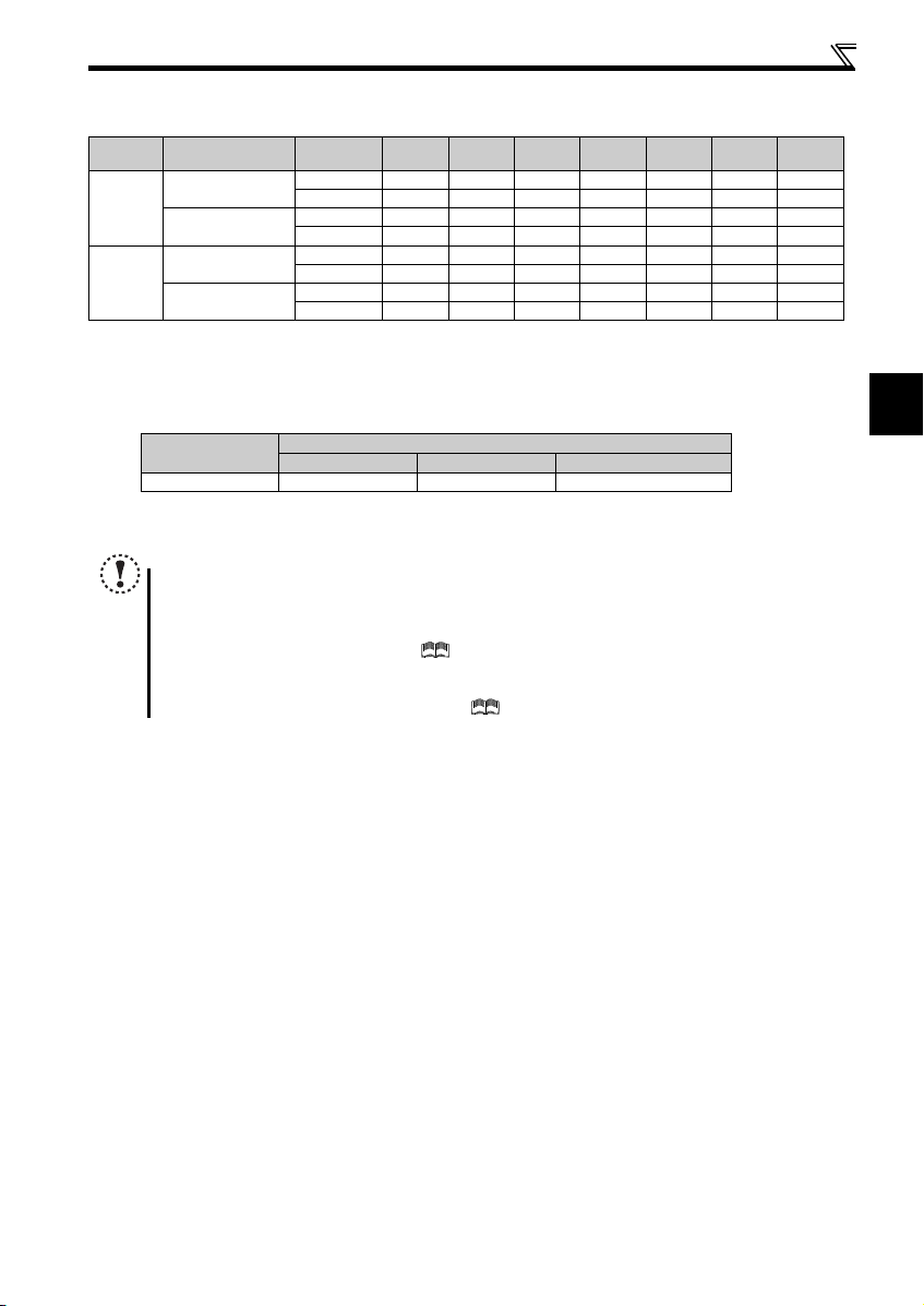
(2) Total wiring length
The overall wiring length for connection of a single motor or multiple motors should be within the value in the table below.
Cable
Typ e
Unshielded
cable
Shielded
cable
When driving a 400V class motor by the inverter, surge voltages attributable to the wiring constants may occur at the
motor terminals, deteriorating the insulation of the motor. Take the following measures 1) or 2) in this case.
1) Use a "400V class inverter-driven insulation-enhanced motor" and set frequency in Pr. 72 PWM frequency selection
2) Connect the surge voltage suppression filter (FR-ASF-H/FR-BMF-H) on the inverter output side.
Pr. 72 Setting
(carrier frequency)
1 (1kHz) or lower
2 (2kHz) or higher
1 (1kHz) or lower
2 (2kHz) or higher
Vol tage
Class
200V class 200m 200m 300m 500m 500m 500m 500m
400V class - - 200m 200m 300m 500m 500m
200V class 30m 100m 200m 300m 500m 500m 500m
400V class - - 30m 100m 200m 300m 500m
200V class 50m 50m 75m 100m 100m 100m 100m
400V class - - 50m 50m 75m 100m 100m
200V class 10m 25m 50m 75m 100m 100m 1 00m
400V class - - 10m 25m 50m 75m 100m
0.1K 0.2K 0.4K 0.75K 1.5K 2.2K
3.7K
or Higher
according to wiring length.
Wiring Length
Carrier frequency
50m or less 50m to 100m Exceeding 100m
14.5kHz or less 8kHz or less 2kHz or less
NOTE
Especially for long-distance wiring, the inverter may be affected by a charging current caused by the stray
capacitances of the wiring, leading to a malfunction of the overcurrent protective function, fast response current limit
function, or stall prevention function or a malfunction or fault of the equipment connected on the inverter output side.
If malfunction of fast-response current limit function occurs, disable this function. If malfunction of stall prevention
function occurs, increase the stall level. ( Refer to Pr. 22 Stall prevention operation level and Pr. 156 Stall prevention
operation selection in Chapter 4 of the FR-E700 Instruction Manual (Applied))
When using the automatic restart after instantaneous power failure function with the wiring length exceeding 100m,
select without frequency search (Pr. 162 = "1, 11"). (
Refer to Chapter 4 of the FR-E700 Instruction Manual (Applied))
14
Wiring
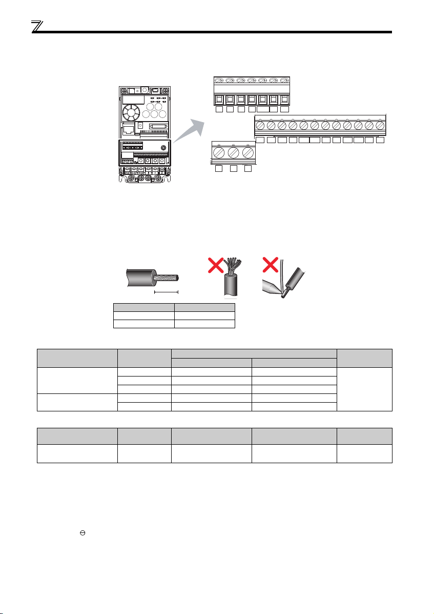
2.3.4 Wiring of control circuit
Terminal layout
Terminal screw size
M3: (Terminal A, B, C)
M2: (Other than the above)
10 2 5 4 RUN FU SE
FM
CBA
RHRMRL
STF STR
PCSD
RESMRS
Wiring method
1) Strip off the sheath of the wire of the control circuit to wire.
Strip off the sheath about the length below. If the length of the sheath peeled is too long, a short circuit may occur
among neighboring wires. If the length is too short, wires might come off.
Wire the stripped wire after twisting it to prevent it from becoming loose. In addition, do not solder it. Use a blade
terminal as necessary.
Wire stripping length
L
Terminal A, B, C 6
Other than the above 5
Blade terminals available on the market: (as of Jan. 2017)
Phoenix Contact Co., Ltd.
Terminal Screw Size
M3 (terminal A, B, C)
M2 (other than the above)
Wire Size (mm2)
0.3 AI 0,34-6TQ A 0,34-7
0.5 AI 0,5-6WH A 0,5-6
0.75 AI 0, 75-6GY A 0,75-6
0.3 AI 0,34-6TQ A 0,34-7
0.5 AI 0,5-6WH A 0,5-6
NICHIFU Co., Ltd.
Terminal Screw Size
M3 (terminal A, B, C)
M2 (other than the above)
Wire Size (mm2)
0.3 to 0.75 BT 0.75-7 VC 0.75 NH 69
2) Loosen the terminal screw and insert the wire into the terminal.
3) Tighten the screw to the specified torque.
Undertightening can cause wire disconnection or malfunction. Overtightening can cause a short circuit or malfunction due
to damage to the screw or unit.
Tightening torque: 0.5N·m to 0.6N·m (terminal A, B, C)
0.22N·m to 0.25N·m (other than the above)
Screwdriver: Small flathead screwdriver (Tip thickness: 0.4mm/tip width: 2.5mm)
L (mm)
With Insulation Sleeve Without Insulation Sleeve
Blade Terminal Product
Ferrule Terminal Model
Number
Insulation Cap Product
Number
Crimping Tool
Name
CRIMPFOX 6
Crimping Tool
Product Number
SDSD
15
2
Wiring
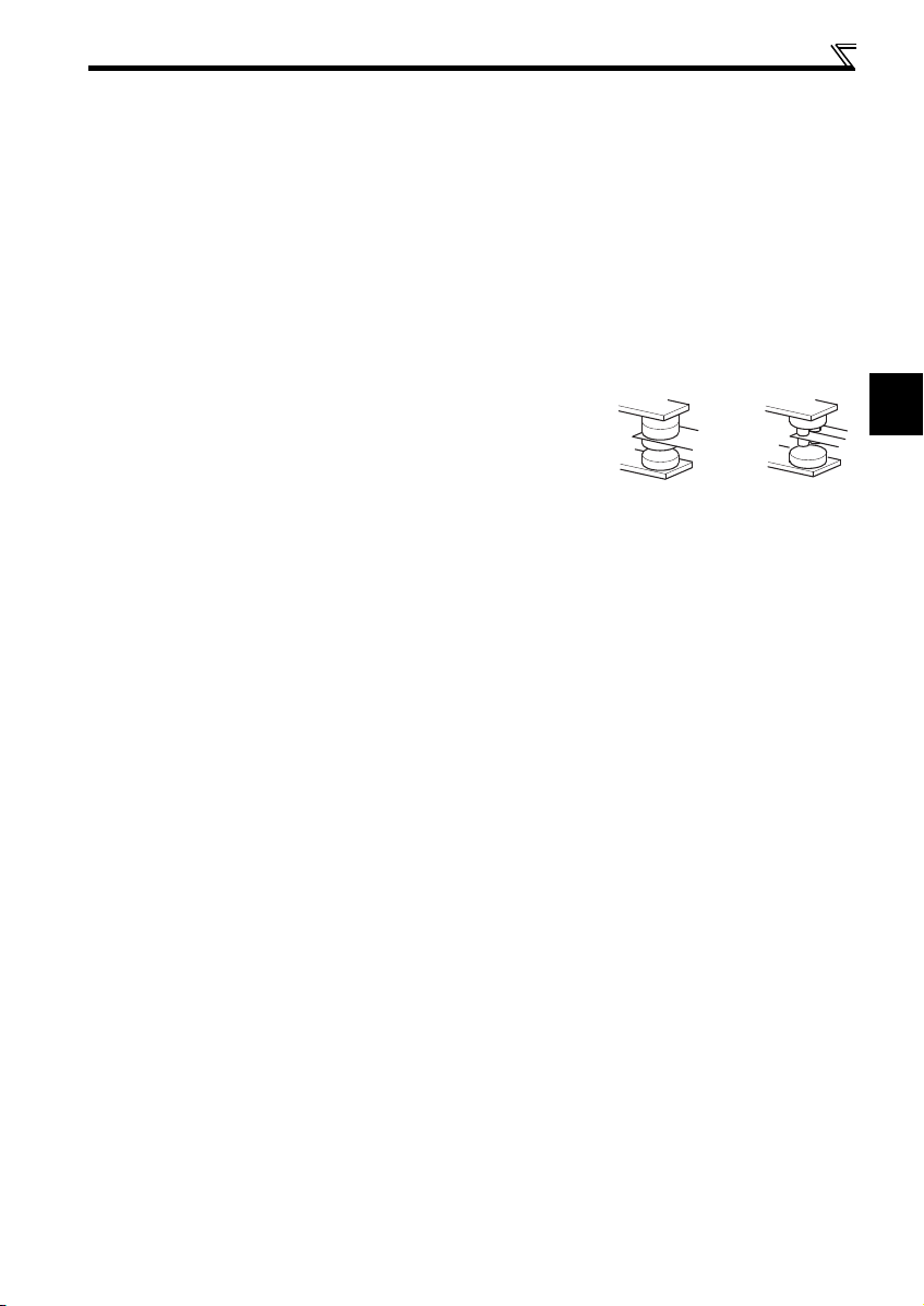
Micro signal contacts Twin contacts
(1) Control circuit common terminals (SD, 5, SE)
Terminals SD, SE and 5 are common terminals for I/O signals. (All common terminals are isolated from each other.) Do not
earth them. Avoid connecting the terminals SD and 5 and the terminals SE and 5.
Terminal SD is a common terminal for the contact input terminals (STF, STR, RH, RM, RL, MRS, RES) and the pulse train
output terminal (FM). The open collector circuit is isolated from the internal control circuit by photocoupler.
Terminal 5 is a common terminal for the frequency setting signals (terminal 2 or 4). It should be protected from external
noise using a shielded or twisted wire.
Terminal SE is a common terminal for the open collector output terminal (RUN, FU). The contact input circuit is isolated
from the internal control circuit by photocoupler.
(2) Wiring instructions
It is recommended to use the wires of 0.3mm2 to 0.75mm2 gauge for connection to the control circuit terminals.
The maximum wiring length should be 30m (200m for terminal FM).
Do not short terminals PC and SD. Inverter may be damaged.
When using contact inputs, use two or more parallel micro-signal contacts or
twin contacts to prevent contact faults since the control circuit input signals are
micro-currents.
To suppress EMI, use shielded or twisted cables for the control circuit terminals and run them away from the main and
power circuits (including the 200V relay sequence circuit). For the cables connected to the control circuit terminals, connect
their shields to the common terminal of the connected control circuit terminal. When connecting an external power supply to
terminal PC, however, connect the shield of the power supply cable to the negative side of the external power supply. Do
not directly earth (ground) the shield to the enclosure, etc.
Always apply a voltage to the fault output terminals (A, B, C) via a relay coil, lamp, etc.
When using an external power supply for transistor output, note the following points to prevent a malfunction caused by
undesirable current.
Do not connect any terminal SD on the inverter and the 0V terminal of the external power supply (when the sink logic is
selected).
Do not connect terminal PC on the inverter and the +24V terminal of the external power supply (when the source logic is
selected).
Do not install an external power source in parallel with the internal 24VDC power source (connected to terminals PC and
SD) to use them together.
Refer to Chapter 2 of the FR-E700 Instruction Manual (Applied) for the detail.
16
 Loading...