

Mitsubishi Electronics FR-E710W, FR-E700, FR-E740, FR-E720S, FR-E720 User Manual

INVERTER
FR-E700
INSTRUCTION MANUAL (BASIC)
FR-E720-0.1K to 15K
FR-E740-0.4K to 15K
FR-E720S-0.1K to 2.2K
FR-E710W-0.1K to 0.75K
Thank you for choosing this Mitsubishi Inverter.
This Instruction Manual (B asic) provides handling info rmation and precautions for use of the equipment.
Please forward this Instru ction Manual (Basic) to the e nd user.
CONTENTS
OUTLINE ...................................................................................1
1
INSTALLATION AND WIRING ...................................................6
2
PRECAUTIONS FOR USE OF THE INVERTER.........................18
3
FAILSAFE OF THE SYSTEM WHICH USES THE INVERTER ...20
4
DRIVING THE MOTOR.............................................................21
5
ENERGY SAVING OPERATION FOR FANS AND PUMPS ........31
6
PARAMETERS .........................................................................32
7
TROUBLESHOOTING ..............................................................37
8
PRECAUTIONS FOR MAINTENANCE AND INSPECTION ........42
9
SPECIFICATIONS....................................................................44
10
To obtain the Instruction Manual (Applied)
Contact where you purchased the inverter, your Mitsubishi sales
representative, or the nearest Mitsubishi FA Center for the following
manual:
y Instruction Manual (Applied) [IB(NA)-0600277ENG]
This manual is required if you are going to utilize functions and
performance.
The PDF version of this manual is also available for download at
"MELFANS Web," the Mitsubishi Electric FA network service on the
world wide web (URL: http://www.MitsubishiElectric.co.jp/melfansweb).
700
1
2
3
4
5
6
7
8
9
10
This Instruction Manual (Basic) provides handling information and precautions for use of the equipment.
Please forward this Instruction Manual (Basic) to the end user.
This section is specifically about safety matters
Do not attempt to install, operate, maintain or inspect th e
inverter until you have read through the Inst ruction Manual
(Basic) and appended documents carefully and can use the
equipment correctly. Do not use this product until you have
a full knowledge of the equipment, safety information and
instructions.
In this Instruction Manual (Basic), the safety instruction
levels are classified into "WARNING" and "CAUTION".
WARNIN G
CAUTION
CAUTION
The level may even lead to a se rious
consequence according to conditions. Both instruction
levels must be followed because these are important to
personal safety.
Incorrect handling m ay cause
hazardous conditions, resulting in
death or severe injur y.
Incorrect handling m ay cause
hazardous conditions, resulting in
medium or slight injury, or may cause
only material damage.
1. Electric Shock Prevention
WARNING
z While power is ON or when the inverter is running, do not
open the front cover. Otherwise you may g et an electric
shock.
z Do not run the inverter with the front cover or wiring cover
removed. Otherwis e you may access the exposed highvoltage terminals or t he charging part of the ci rcuitry and
get an electric shock.
z Even if power is OFF, do not remove the front cover
except for wiring or periodic inspection. You may
accidentally touch the charged inverter circuits and get an
electric shock.
z Before wiring or insp ection, power must be sw itched OFF.
To confirm that, LED indication of the operation panel
must be checked. (It must be OFF.) Any person who is
involved in wiring o r inspection shall wait for at least 10
minutes after the power supply has been switched OFF
and check that there are n o residual voltage using a tester
or the like. The capacitor is charged with high voltage for
some time after power OFF, and it is dangerous.
z
This inverter must be earthed (grounded). Earthing
(grounding) must conform to the requirements of national
and local safety regulations and electrical code (NEC section
250, IEC 536 class 1 and other appli cable standards).
A neutral-point earthed (grounded) power supply for 400V
class inverter in compliance with EN standard must be used.
z Any person who is involved in wiring or inspection of this
equipment shall be f ully competent to do the wor k.
z The inverter must be installed before wiring. Otherwise
you may get an elect ric shock or be injured.
z Setting dial and key operations must be performed with
dry hands to prevent an electric shock.
z Do not subject the c ables to scratches, excess ive stress,
heavy loads or pinc hing. Otherwise you may get an
electric shock.
z Do not change the cooling f an while power is ON. It is
dangerous to change the cooling fan while power is ON.
z Do not touch the printed circuit board or handle the
cables with wet hands. Otherwise you may get an electric
shock.
z When measuring th e main circuit capacitor ca pacity, the
DC voltage is applied to the motor for 1s at powering OFF.
Never touch the motor terminal, etc. right after powerin g
OFF to prevent an e lectric shock.
2. Fire Prevention
CAUTION
z Inverter must be installed on a nonflammable wall without
holes (so that nobody touches the inverter heatsink on the
rear side, etc.). Mounting it to or near flammable material
can cause a fire.
z If the inverter has become faulty, the inverter pow er must
be switched OFF. A continuous flow of large current could
cause a fire.
z When using a brake res istor, a sequence that will turn OFF
power when a fault signal is output must be configured.
Otherwise the brak e resistor may overheat due to damage
of the brake transi stor and possibly cause a fire.
z Do not connect a resistor directly to the DC terminals P/+
and N/-. Doing so could cause a fire.
3.Injury Prevention
CAUTION
z The voltage applied to each terminal must be the ones
specified in the Instruction Manual. Otherwise burst,
damage, etc. may occur.
z The cables must be connected to the correct terminals.
Otherwise burst, dam age, etc. may occur.
z Polarity must be cor rect. Otherwise burst, damage, etc.
may occur.
z While power is ON or for some time after power-OFF, do
not touch the inver ter as they will be extr emely hot. Doing
so can cause burns.
4. Additional Instructions
Also the following points must be noted to prevent an
accidental failure, injury, electric shoc k, etc.
(1) Transportation and Mounting
CAUTION
z The product must be transported in correct method that
corresponds to the weight. Failure to do so may lead to
injuries.
z Do not stack the boxes c ontaining inverters higher th an
the number recommended.
z The product must be installed to the position where
withstands the weight of the product according to the
information in the Instruction Manual.
z Do not install or operate the inverter if it is damaged or
has parts missing.
z When carrying the inverter, do not hold it by the front
cover or setting dial; it may fall off or fail.
z Do not stand or rest heavy objects on the product.
z The inverter mounting orientation must be correct.
z Foreign conductive objects must be prevented from
entering the inverter. That includes screws and metal
fragments or other flammable substance such as oil.
z As the inverter is a precision instrument, do not drop or
subject it to impact.
z The inverter must be used under the following
environment. Other wise the inverter may be damaged.
Surroundi ng
air
temperature
Ambient
humidity
Storage
temperature
Atmosphere
Environment
Altitude/
vibration
∗1 Temperature appl icable for a short time, e.g . in transit.
-10°C to +50°C (non-freezing)
90%RH or less (non-condensing)
-20°C to +65°C *1
Indoors (free from corros ive gas, flammable gas,
oil mist, dust and dirt)
Maximum 1,000m above sea level.
2
or less at 10 to 55Hz (directions of X, Y, Z
5.9m/s
axes)
A-1
(2) Wiring
CAUTION
z Do not install a power factor correction capacitor or sur ge
suppressor/capacitor type filter on the inverter output
side. These devices on the inverter output side may be
overheated or burn out.
z The connection orientation of the output cables U, V, W to
the motor affects the rotation direction of the motor.
(3) Trial run
CAUTION
z Be fore starting operation, each parameter must be
confirmed and adjusted. A fai lure to do so may cause
some machines to make unexpected motions.
(4) Usage
WARNING
z An y person must stay away from the equipment w hen the
retry function is set as it will restart suddenly after trip.
z S ince pressing key may not stop output dependin g
on the function setting status, separate circ uit and switch
that make an emerg ency stop (power OFF, mechanical
brake operation for emer gency stop, etc.) must be
provided.
z OFF status of the start signal must be confirmed before
resetting the inv erter fault. Resettin g inverter alarm wit h
the start signal ON restarts the motor suddenly.
z
The inverter mu st be used for thre e-phase induction motors.
Connection of any other electrical equipment to the
inverter output may damage the equipment.
z Do not modify the equipment.
z
Do not perform parts removal which is not in structed in this
manual. Doing so may lead to fault or damage of the product.
(5) Emergency stop
CAUTION
z A s afety backup such as an em ergency brake must be
provided to prevent hazardous condition to the machine
and equipment in ca se of inverter failure.
z W hen the breaker on the inverter input side trips, the
wiring must be checked for fault (short circuit), and
internal parts of the inverter for a damage, etc. The cause
of the trip must be identified and removed before turning
ON the power of the b reaker.
z W hen any protective function is activated, ap propriate
corrective action must be taken, and the inverter must be
reset before resuming operation.
(6) Maintenance, inspection and parts replacement
CAUTION
z Do not carry out a megger (insulation resistance) test on
the control circuit of the inverter. It will cause a failure.
(7) Disposal
CAUTION
z T he inverter must be trea ted as industrial waste.
General instruction
Many of the diagrams and dr awings in this Instruction
Manual (Basic) show the inverter without a cover or partially
open for explanation. Never operate the inverter in this
manner. The cover must be alway s reinstalled and the
instruction in this Instruct ion Manual (Basic) must be
followed when operating the inverter.
z The electronic thermal relay function does not guarantee
CAUTION
protection of the motor from overheating. It is
recommended to install bo th an external thermal and PT C
thermistor for overh eat protection.
z Do not use a magnetic contactor on the inverter input for
frequent starting/stopping of the inverter. Otherwise the
life of the inverter decreases.
z T he effect of electrom agnetic interference m ust be
reduced by using a noise filter or by other means.
Otherwise nearby e lectronic equipment ma y be affected.
z Appr opriate measures must be taken to suppress
harmonics. Otherwise power supply harmonics from the
inverter may heat/dam age the power factor co rrection
capacitor and generator.
z W hen driving a 400V class motor by th e inverter, the
motor must be an insulation-enhanced motor or measures
must be taken to suppress surge voltage. Surge voltage
attributable to the wiring constants may occur at the
motor terminals, deteriorating the insulation of the motor.
z W hen parameter clear or a ll parameter clear is perf ormed,
the required paramete rs must be set agai n before starting
operations becau se all parameters return t o the initial value.
z The inverter can be easily set for high-speed operation.
Before changing its setting, the performances of the
motor and machine must be fully examined.
z Stop status cannot be hold by the inverter's brake
function. In addition to t he inverter’s brake function, a
holding device must be installed to ensure safety.
z Be fore running an inverter which had been stored for a long
period, inspection and test operation must be performed.
z F or prevention of damage due t o static electricity, nearby
metal must be touched before touching this product to
eliminate static electricity from your body.
A-2
<Abbreviation>
y PU: Operatio n panel and parameter unit (FR-PU04, FR-PU07)
y Inverter: Mitsubishi inve rter FR-E700 series
y FR-E700: Mitsubishi inverter FR-E700 series
y Pr.: Parameter number (Number assigned to function)
y PU operation: Operation using the PU (operation panel/FR-PU04/FR-PU07)
y External operation: Operation using the control circuit signals
y Combined operation : Operation using the PU (FR-PU04/FR-PU07) and external operation
y Standard motor : SF-JR
y Constant torque motor : SF-HRCA
<Trademark>
y LONWORKS® is a registered trademark of Echelon Corporation in the U.S.A and other cou ntries.
y Company and product names herein are the trademarks and registered trademarks of their respective owners.
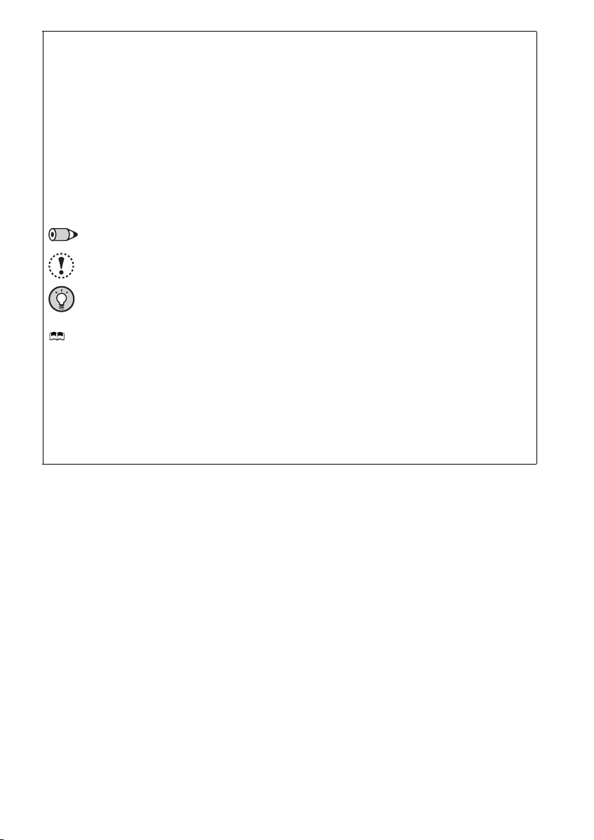
<Mark>
REMARKS: Additional helpful contents and relations with other functions are written.
Note: Contents requiring caution or cases when set functions are not activated are written.
POINT: Useful contents and points are written.
<Related document>
Refer to the Instruction Manual (Applied) for further information on the following points.
y Removal and reinstallation of the cover
y Connection of stand-alone option unit
y EMC and leakage currents
y Detailed explanation on parameters
y Troubleshooting
y Check first when you have a trouble
y Inspection items (life diagnosis, cooling fan replacement)
y Measurement of main circuit voltages, currents and powers
y For customers who are replacing the conventional model with this inverter
A-3
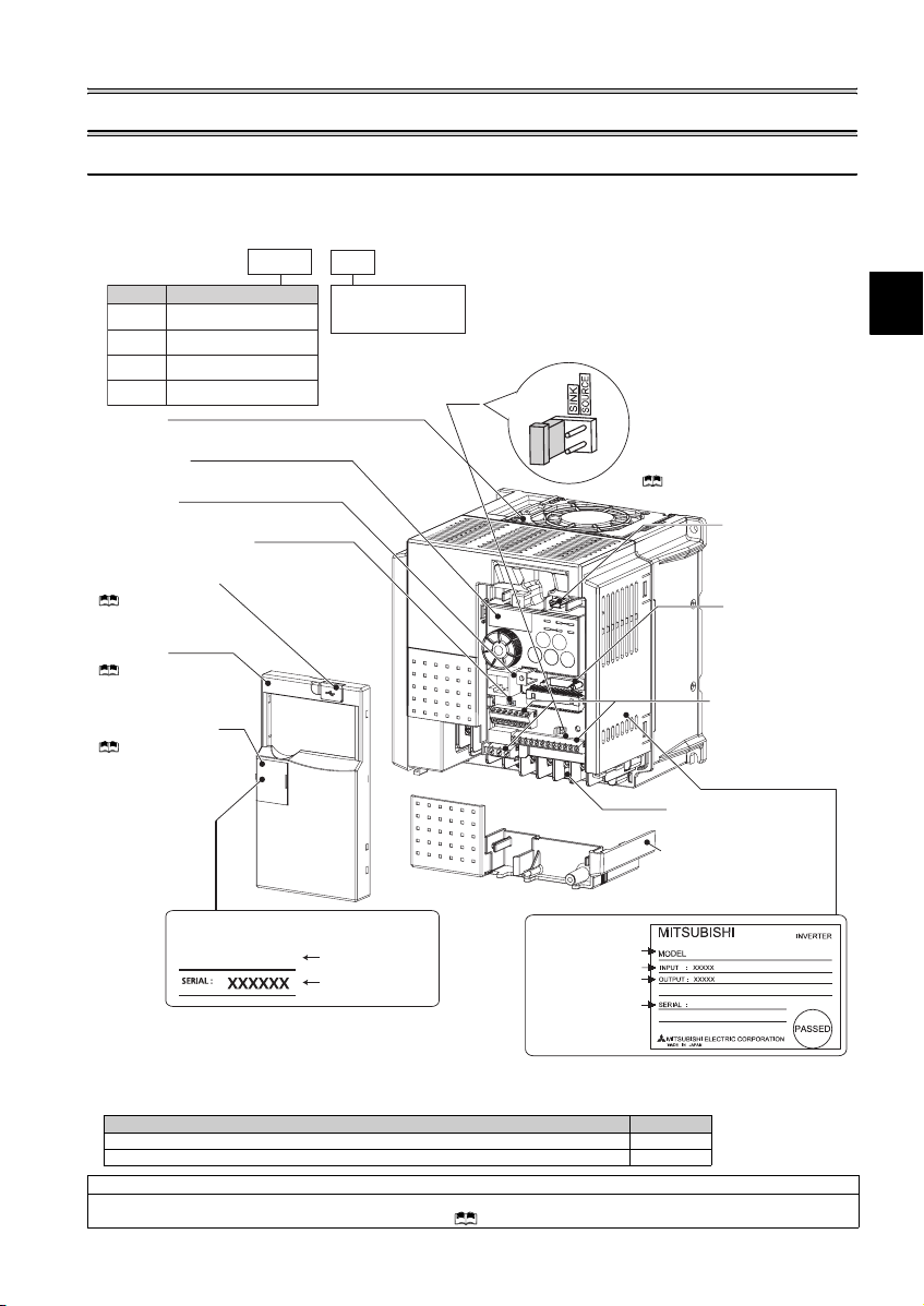
Product checking and parts identification
1 OUTLINE
1.1 Product checking and parts identification
Unpack the inverter and check the capacity plate on the front cover and the rating plate on the inverter side face to ensure that
the product agrees with your order and the inverter is intact.
zInverter model
--
E740 3.7
FR
No. Voltage class
Three-phase 200V class
E720
Three-phase 400V class
E740
Single-phase 200V class
E720S
Single-phase 100V class
E710W
Cooling fan
The cooling fan is removable.
Operation panel
(Refer to page 2)
PU connector
(Refer to page 9)
Voltage/current input switch
(Refer to page 9)
USB connector cover
Refer to the Instruction
Manual (Applied) for how to
open the cover.
Front cover
Refer to the Instruc tion
Manual (Applied) for
installation/removal.
PU connector cover
Refer to the
Instruction Manual
(Applied) for how to
open the cover.
Capacity plate
FR-E740-3.7K
K
Represents the
inverter capacity [kW]
Inverter model
Serial number
Example of FR-E740-3.7K
Rating plate
Inverter model
Input rating
Output rating
Serial number
Control logic switchover jumper
connector
The jumper connector is in the sink logic
(SINK) when shipped from the factory.
Move the jumper connector to change to
the source logic (SOURCE). Always fit the
jumper connector to the either position.
( Refer to the Instruction Manual (Applied))
USB connector
(mini-B conne ctor)
(Refer to page 9)
Connector for plug-in
option connection
(Refer to the instruction
manual of options.)
Control circuit terminal
block
(Refer to page 10)
Main circuit terminal block
(Refer to page 10)
Combed shaped wiring cover
Refer to the Instruction Manual
(Applied) for installation/removal.
FR-E740-3.7K
1
• Accessory
· Fan cover fixing screws (M3 × 35mm)
These screws are necessary for compliance with the EU Directive (
FR-E720-1.5K to 3.7K, FR-E740-1.5K to 3.7K, FR-E720S-0.75K to 2.2K 1
Harmonic suppression guideline (when inverters are used in Japan)
All models of general -purpose inverters used by specific consumers are covered by "Harmonic su ppression guideline for co nsumers who
receive high voltage or spe cial high voltage". (For furth er details, refer to Chapter 3 of the Instruction Manual (Applied).)
FR-E720-5.5K to 15K, FR-E740-5.5K to 15K 2
Capacity Quantity
Refer to page 47
)
1
Operation panel
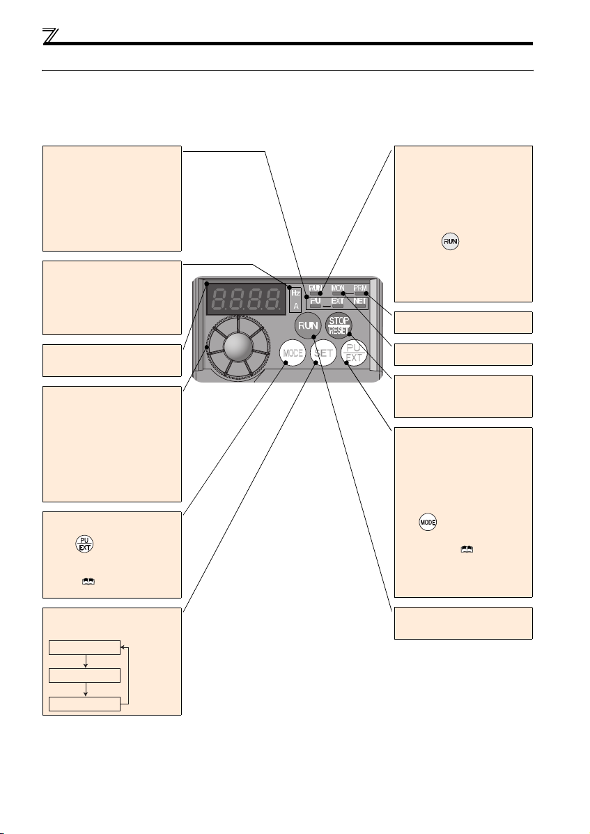
1.2 Operation panel
1.2.1 Names and functions of the operation panel
The operation panel cannot be removed from the inverter.
Operation mode indicator
PU: Lit to indicate P U operation mode.
Lit to indicate External operation mode.
EXT:
(Lit at power-ON at initial setting.)
NET: Lit to indicate Network operation
mode.
PU, EXT: Lit to indicate External/PU
combined operation mode 1, 2.
These turn OFF whe n command source is
not on oper ation panel.
Unit indicator
Hz: Lit to indicate frequency.
(Flickers when the set frequency
monitor is displayed.)
A: Lit to indicate current.
(Both "Hz" and "A" turn OFF when other
than the above is displayed.)
Monitor (4-digit LED)
Shows the f requency, parameter numb er,
etc.
Setting dial
(Setting dial: Mitsubishi inverter dial)
Used to change the frequency setting and
parameter settings.
Press to disp lay the following.
y Displays the set frequency in the
monitor mode
y Present set value is displayed during
calibration
y Displays the order in the faults history
mode
Mode switch over
Used to change each setting mode.
Pressing simultaneously changes
the operation mode.
Pressing for a while (2s) can lock
operation. ( Refer to the Instruction
Manual (Applied))
Determination of each setting
If pressed during operation, monitor
changes as below:
Running frequency
Operating status indicator
Lit or flicker during inverter operation.
* Lit: When the forward rotation operation
is being performed.
Slow flickering (1.4s cycle):
When the reverse operation is being
performed.
Fast flickering (0.2s cycle):
When was pressed or the
start command was given, but the
operation cannot be made.
yWhen the frequency command is less
than the starting frequency.
yWhen the MRS signal is input.
Parameter setting mode
Lit to indicate paramete r setting mode.
Monitor indicator
Lit to indicate monitoring mode.
Stop operation
Used to stop Run command.
Fault can be reset when protective
function is activated (fault).
Operation mode switchover
Used to switch between the PU and
External operation mode.
When using the External operation mode
(operati on using a separat ely connecte d
frequency setting potentiometer and start
signal), press this key to light up t he EXT
indication.
(Press simultaneously (0.5s) o r
change Pr. 79 setting to change to
combined mode .) ( Refer to the
Instruction Manual (Applied))
PU: PU operation mode
EXT:External operation mode
Cancels PU stop also.
Start command
The rotation direction can be selected by
setting Pr. 40.
∗
Output current
Output voltage
2
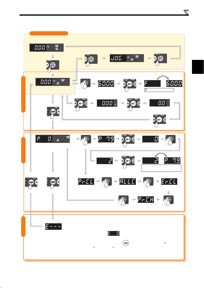
1.2.2 Basic operation (factory setting)
Operation mode switchover
At power-ON (External operation mode)
Operation panel
PU operation mode
(output frequency monitor)
Parameter setting mode
Parameter settingFaults history Monitor/frequency setting
PU Jog operation mode
Value change
Output current monitor
Value change
Parameter clear All parameter
STOP
clear
(Example)
and frequency flicker.
Frequency setting has been
written and completed!!
Output voltage monitor
Display the
present setting
(Example)
Parameter and a setting value
flicker alternately.
Parameter write is completed!!
Faults history clear
1
Initial value
change list
[Operation for displaying faults history]
Past eight faults can be displayed.
(The latest fault is ended by ".".)
When no fault history exists, is displayed.
While a fault is displayed:
The display shifts as follows by pressing : Output frequency at the fault
Output current Output voltage Energization time.
(After Energization time, it goes back to a fault display.)
Pressing the setting dial shows the fault history number.
(Refer to page 38)
3
Operation panel
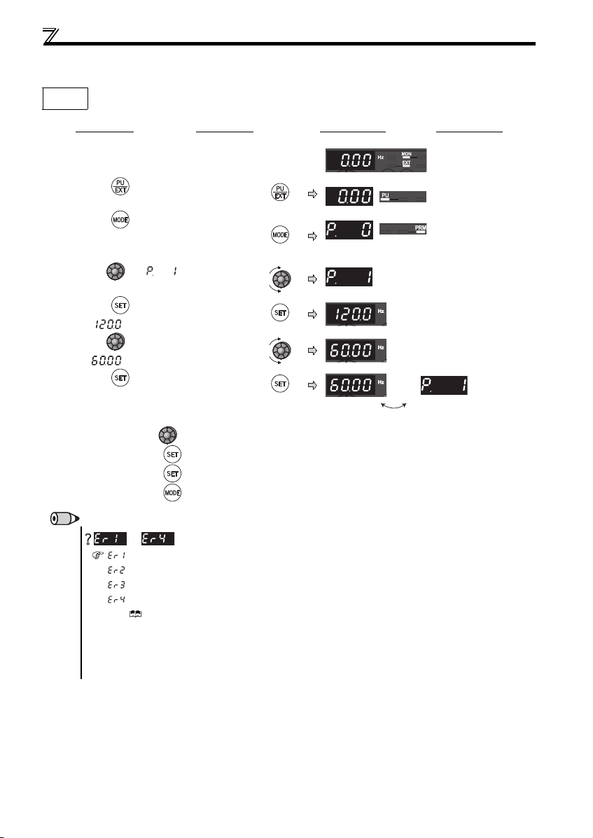
1.2.3 Changing the parameter setting value
Changing
example
Change the Pr. 1 Maximum frequency setting.
Operation Display
Screen at power-ON
1.
The monitor display ap pears.
2. P ress to choose the PU operation mo de.
3. P ress to choose the parameter setting
mode.
4. Turn until (Pr. 1) appears.
5. P ress to read the currently set value.
" "(120.0Hz (initial value) ) appears.
6. Turn to change the se t value to
" " (60.00Hz).
7. P ress to set.
y Turn to read another parameter.
y Press to show the setting again.
y Press twice to show the next parame ter.
y Press twice to return the monito r to frequency monitor.
PU indicator is lit.
PRM indicator is lit.
(The parameter number re ad previously appears.)
Flicker...Parameter setting complete!!
REMARKS
to
appears .................... Write disable error
appears .................... Write error during operat ion
appears ....................Ca libration error
appears ....................M ode designation error
(For details, Refer to the Instruction Manual (Applied) .)
y The number of digits displayed on the operation panel is four. Only the upper four digits of values can be displayed and set. If the
values to be displayed have five digits or more including decimal places, the fifth or later numerals can not be displayed nor set.
(Example ) For Pr. 1
When 60Hz is set, 60. 00 is displayed.
When 120Hz is set, 12 0.0 is displayed and second decimal place is not dis played nor set.
is displayed...Why?
4
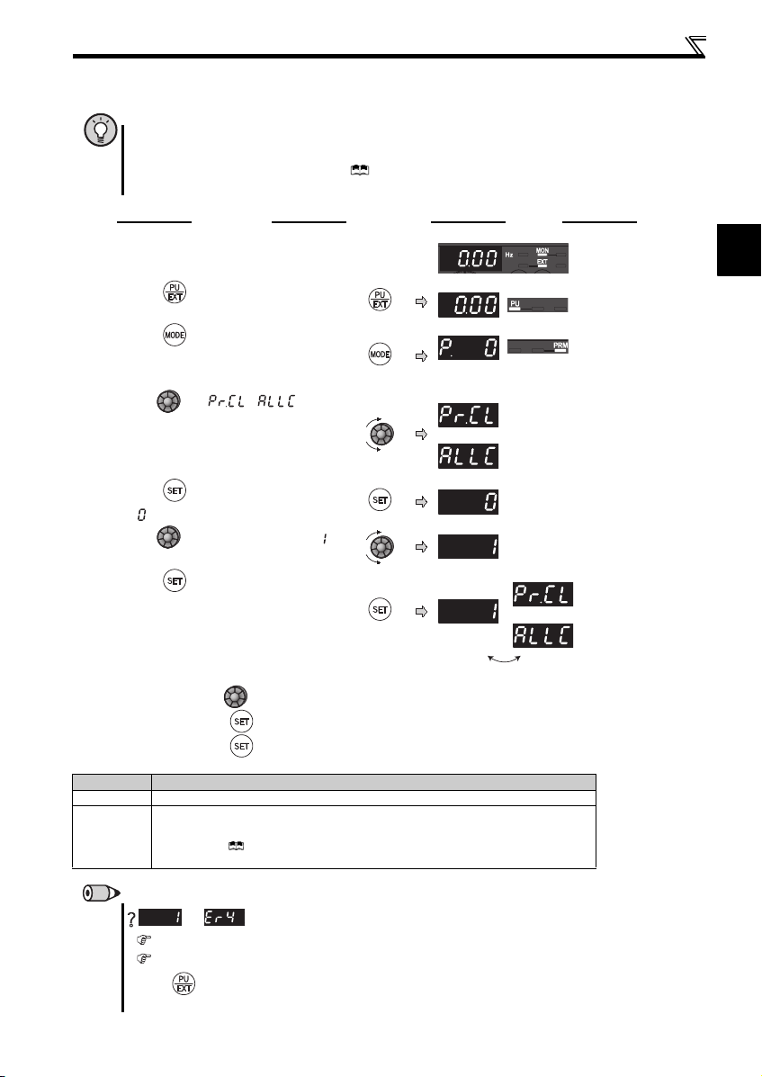
1.2.4 Parameter clear/all parameter clear
POINT
y Set "1" in Pr.CL Parameter clear, ALLC all parameter clear to initialize all parameters. (Parameters are not cleared
when "1" is set in Pr. 77 Parameter write selection.)
y Refer to the extended parameter list of the Instruction Manual (Applied) for parameters cleared with this
operation.
Operation Display
Screen at power-ON
1.
The monitor display app ears.
2. Press to choose th e PU operation mode.
Operation panel
1
PU indicator is lit.
3. Press to choose t he parameter setting
mode.
4. Turn until ( ) appears.
5. Press to read the c urrently set value.
" "(initial value) appears.
6. Turn to change it to the set val ue " ".
7. Press to set.
Flicker ··· Parameter setting complete!!
y Turn to read another parameter.
y Press to show the setting again.
y Press twice to show the next paramet er.
Setting Description
0 Not executed.
Sets parameters back to th e initial values. (Parame ter clear sets back all paramete rs except
calibration parameters and term inal function selection parameters to the initial values.) Refer to the
1
parameter list of the I nstruction Manual (Applied) for availabi lity of parameter clear and a ll
parame ter cl ear.
PRM indic ator is lit.
(The parameter number r ead previously appears.)
Parameter clear
All parameter clear
Parameter clea r
All parameter clear
REMARKS
and
The inverter is not in the PU operation mode.
PU connector or USB c onnector is used.
1. Press . [PU] is lit and the monitor (4-digit LED) displays "1" . (When Pr. 79 = "0" (initial value))
2. Carry out operation from step 6 again.
are displayed alternately ... Why?
5
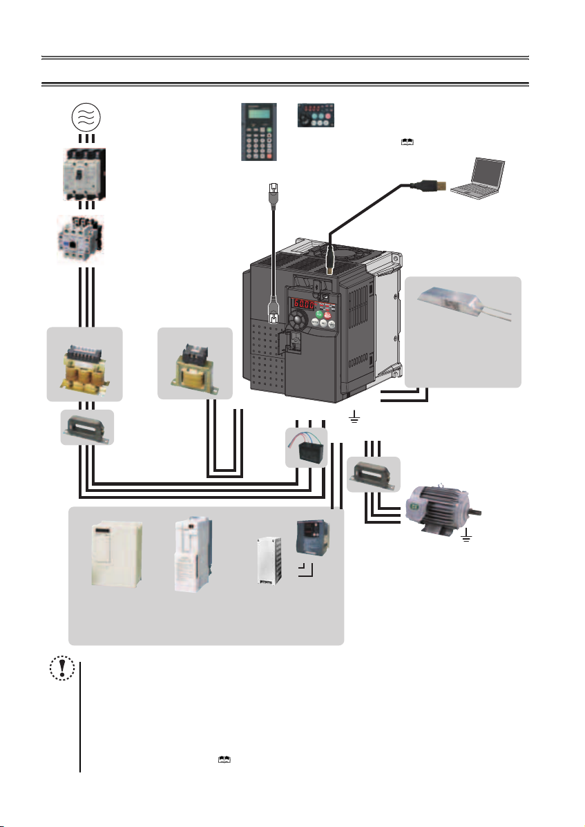
2 INSTALLATION AND WIRING
AC power supply
Use within the permissible power supply
specifications of the inverter. To ensure
safety, use a moulded case circuit breaker,
earth leakage circuit breaker or magnetic
contactor to switch power ON/OFF.
(Refer to page 44)
Moulded case circuit breaker
(MCCB) or earth leakage circuit
breaker (ELB), fuse
The breaker must be selected carefully
since an in-rush current flows in the
inverter at power ON.
(Refer to page 7)
Magnetic contactor (MC)
Install the magnetic contactor to ensure
safety. Do not use this magnetic contactor
to start and stop the inverter. Doing so will
cause the inverter life to be shorten.
(Refer to page 7)
Reactor (FR-HAL, FR-HEL option)
Reactors (option) must be used when
power harmonics measures are taken,
the power factor is to be improved or the
inverter is installed near a large power
supply system (500kVA or more). The
inverter may be damaged if you do not
use reactors. Select the reactor according
to the model. Remove the jumpers across
AC reactor (FR -HAL)
* Filterpack (FR-BFP2), which contains DC reactor and EMC filter in one package, is also available.
terminals P/+ and P1 to connect the DC reactor.
Install
to reduce the electromagnetic
noise generated from the
inverter. Effective in the range
from about 1MHz to 10MHz.
When more wires are passed
through, a more effective result
can be obtained. A wire should
be wound four turns or more.
DC reactor (FR-HEL) *
EMC filter (ferrite core) *
(FR-BSF01, FR-BLF)
an EMC filter (ferrite core)
Parameter unit
(FR-PU07)
P1
P/+
EMC filter
(capacitor) *
(FR-BIF)
Reduces the
radio noise.
Inverter (FR-E700)
Brake unit
(FR-BU2)
Enclosure surface
operation panel
(FR-PA07)
By connecting the connection
cable (FR-CB2) to the PU
connector, operation can be
performed from FR-PU07,
FR-PA07.
R/L1 S/L2T/L3
Earth (Ground)
P/+
N/-
USB connector
A personal computer and an inverter
can be connected with a
USB (Ver1. 1) cable.
( Refer to Chapter 3 of the
Instruction Manual (Applied))
Brake resistor
(FR-ABR, MRS type, MYS type)
Braking capabili ty can be improved. (0.4K
or higher)
Always install a t hermal relay when using
a brake resistor whose capacity is 11K or
higher.
P/+
PR
EMC filter (ferrite core)
(FR-BSF01, FR-BLF)
an EMC filter (ferrite core)
Install
UW
to reduce the electromagnetic
V
noise generated from the inverter.
Effective in the range from about
1MHz to 10MHz. A wire should be
wound four turns at a maximum.
(Refer to page 17)
Motor
High power factor
converter (FR-HC)
Power supply harmonics
can be greatly suppressed.
Install this as required.
6
P/+
P/+
PR
Power regeneration
common converter
(FR-CV)
Great braking capability
is obtained.
Install this as required.
NOTE
y The life of the inverter is influenced by surrounding air temperature. The surrounding air temperature should be as low as
possible within the p ermissible range. This m ust be noted especi ally when the inverter is installed in an enclosure. (Refer
to page 8)
y Wrong wiring might lead to damage of the inverter. The control signal lines must be kept fully away from the main circuit
to protect them from noise. (Refer to page 9)
y Do not install a power factor correction capacitor, surge suppressor or capacitor type filter on the inverter output side.
This will cause the i nverter to trip or the c apacitor and surge suppress or to be damaged. If any of the above dev ices are
connected, immediately remove them.
y Electromagne tic wave interference
The input/output (main circuit) of the inverter includes high frequency components, which may interfere with the
communication devices (such as AM radios) used near the inverter. In this case, install options among the capacitor type
EMC filter FR-BIF (for use in the input side only), the ferrite core type EMC filter FR-BSF01/FR-BLF, filterpack, and EMC
filter to minimize the interferen ce. ( Refer to Chapter 3 of the Instruction Manual (Applied)).
y Refer to the instructi on manual of each option and peripher al devices for details of peripheral devi ces.
Resistor unit (FR-BR)
Discharging resistor (GZG, GRZG)
The regenerative braking capability
of the inverter can be exhibited fully.
Install this as required.
surge suppressor or capacitor type filter on the output
side of the inverter. When installing a moulded case
circuit breaker on the output side of the inverter,
contact each manufacturer for selection of the
moulded case circuit breaker.
Earth (Ground)
To prevent an electric shock, always earth (ground)
the motor and inverter. For reduction of induction noise
from the power line of the inverter, it is recommended
to wire the earthing cable by returning it to the earth
(ground) terminal of the inverter.
Devices connected to the output
Do not install a power factor correction capacitor,
PR
Earth (Ground)
Peripheral devices
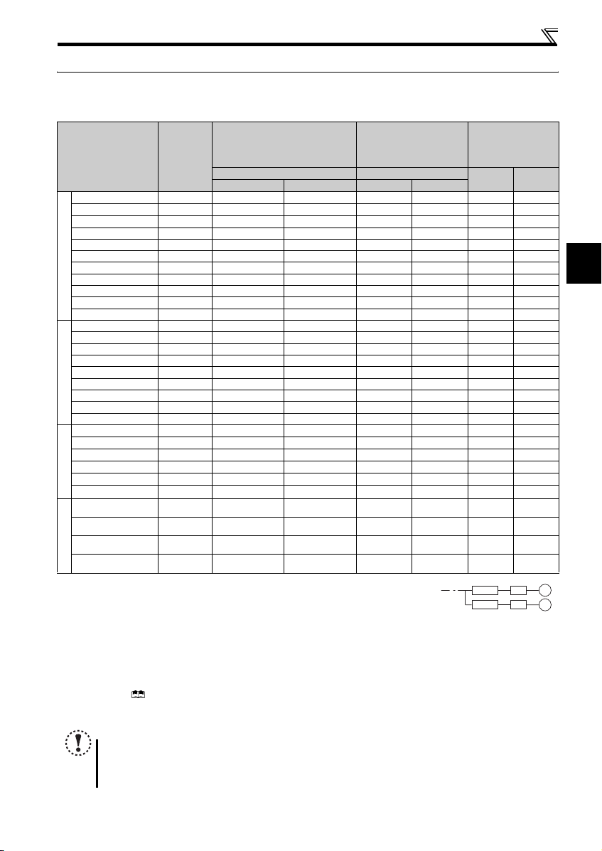
2.1 Peripheral devices
Check the inverter model of the inverter you purchased. Appropriate peripheral devices must be selected according to the capacity.
Refer to the following list and prepare appropriate peripheral devices.
Moulded Case Circuit Breaker
Applicable Inverter
Model
Motor
Output
(kW)
or Earth Leakage Circuit Breaker
(MCCB) ∗1
(ELB) ∗2
Reactor connection Reactor connection
without with without with
FR-E720-0.1K 0.1 5A 5A S-N10 S-N10 0.4K ∗5 0.4K ∗5
FR-E720-0.2K 0.2 5A 5A S-N10 S-N10 0.4K
FR-E720-0.4K 0.4 5A 5A S-N10 S-N10 0.4K 0.4K
FR-E720-0.75K 0.75 10A 10A S-N10 S-N10 0.75K 0.75K
FR-E720-1.5K 1.5 15A 15A S-N10 S-N10 1.5K 1.5K
FR-E720-2.2K 2.2 20A 15A S-N10 S-N10 2.2K 2.2K
FR-E720-3.7K 3.7 30A 30A S-N20, S-N21 S-N10 3.7K 3.7K
FR-E720-5.5K 5.5 50A 40A S-N25 S-N20, S-N21 5.5 K 5.5K
Three-Phase 200V
FR-E720-7.5K 7.5 60A 50A S-N25 S-N25 7.5K 7.5K
FR-E720-11K 11 75A 75A S-N35 S -N35 11K 11K
FR-E720-15K 15 125A 100A S-N50 S-N50 15K 15K
FR-E740-0.4K 0.4 5A 5A S-N10 S-N10 H0.4K H0.4K
FR-E740-0.75K 0.75 5A 5A S-N10 S-N10 H0.75K H0.75K
FR-E740-1.5K 1.5 10A 10A S-N10 S-N10 H1.5K H1.5K
FR-E740-2.2K 2.2 15A 10A S-N10 S-N10 H2.2K H2.2K
FR-E740-3.7K 3.7 20A 15A S-N10 S-N10 H3.7K H3.7K
FR-E740-5.5K 5.5 30A 20A S-N20, S-N21 S-N11, S-N12 H5.5K H5.5K
FR-E740-7.5K 7.5 30A 30A S-N20, S-N21 S-N20, S-N21 H7.5K H7.5K
Three-Phase 400V
FR-E740-11K 11 50A 40A S-N20, S-N21 S-N20, S- N21 H11K H11K
FR-E740-15K 15 60A 50A S-N25 S-N2 0, S-N21 H15K H15K
FR-E720S-0.1K 0.1 5A 5A S-N10 S-N10
FR-E720S-0.2K 0.2 5A 5A S-N10 S-N10
FR-E720S-0.4K 0.4 1 0A 10A S-N10 S-N10
FR-E720S-0.75K 0.75 15A 10A S-N10 S-N10
FR-E720S-1.5K 1.5 2 0A 20A S-N10 S-N10
FR-E720S-2.2K 2.2 4 0A 30A S-N20, S-N21 S-N10
Single-Phase 200V
FR-E710W-0.1K 0.1 10A 5A S-N10 S-N10
FR-E710W-0.2K 0.2 10A 10A S-N10 S-N10
FR-E710W-0.4K 0.4 15A 15A S-N10 S-N10
FR-E710W-0.75K 0.75 30A 20A S-N10 S-N10
Single-Phase 100V
∗1 ySelect an MCCB according to the power supply capacity.
yInstall one MCCB per inverter.
∗2 For the use in the United States or Canada, select a UL and cUL certified fuse with Class T fuse equivalent cut-off
speed or faster with the appropriate rating for branch circuit protection. Alternatively, select a UL489 molded case circuit breaker (MCCB). (Refer to page 50)
∗3 Magnetic contactor is selected based on the AC-1 class. The electrical durability of magnetic contactor is 500,000 times. When the magnetic contactor is
used for emergency stop during motor driving, the electrical durability is 25 times.
When using the MC for emergency stop during motor driving or using on the motor side during commercial-power supply operation, select the MC with c lass
AC-3 rated current for the motor rated current.
∗4 When connecting a single-phase 100V power input inverter to a power transformer (50kVA or more), install a AC reactor (FR-HAL) so that the performance
is more reliable. ( Refer to Chapter 3 of the Instruction Manual (Applied))
∗5 The power factor may be slightly lower.
∗6 Single-phase 100V power input model is not compatible with DC reactor.
NOTE
y When the inver ter capacity is larger than the motor capacity, select an MCCB and a magnetic contactor according to
the inverter model and cable and reactor according to the motor output.
y When the breaker on the inverter input side trips, check for the wiring fault (short circuit), damage to internal parts of
the inverter, etc. Identify the ca use of the trip, then rem ove the cause and power O N the breaker.
Magnetic Contactor (MC)
∗3
Reactor
FR-HAL FR-HEL
∗5 0.4K ∗5
∗5 0.4K ∗5
0.4K
∗5 0.4K ∗5
0.4K
∗5 0.75K ∗5
0.75K
∗5 1.5K ∗5
1.5K
∗5 2.2K ∗5
2.2K
∗5 3.7K ∗5
3.7K
0.75K ∗4
,
∗5
−−− ∗ 6
∗4, ∗5 −−− ∗ 6
1.5K
∗4, ∗5 −−− ∗ 6
2.2K
∗4, ∗5 −−− ∗ 6
3.7K
MCCB INV
MCCB INV
IM
IM
2
7
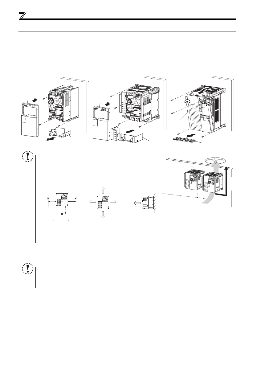
Installation of the inverter and instructions
2.2 Installation of the inverter and instructions
(1) Installation of the inverter
Enclosure surface mounting
Remove the front cover and wiring cover to fix the inverter to the surface. (Remove the covers in the directions of the arrows.)
FR-E720-0.1K to 0.75K
FR-E720S-0.1K to 0.4K
FR-E710W-0.1K to 0.4K
FR-E720-1.5K to 3.7K
FR-E740-0.4K to 7.5K
FR-E720S-0.75K or higher
FR-E710W-0.75K
FR-E720-5.5K to 15K
FR-E740-11K, 15K
Front cover
Wiring cover
Front cover
Wiring cover
Note
y When encasing mu ltiple inverters, install them in parallel as a cooling
measure.
y Install the inverter ve rtically.
y For heat dissipatio n and maintenance, tak e at least the clear ances
shown in the table below from the inverter to the other devices and to
the enclosure surface .
Measurement
position
5cm
5cm
1cm or
more
5cm
Measurement
position
-10 C to +50 C
(non-freezing)
∗1 Take 5cm or more clearances for 5.5K or higher.
∗2 When using the inverters at the surrounding air temperature of 40°C or less, the inverters can be installed without any clearance between
them (0cm clearance).
∗1, ∗2
10cm or more
1cm or
∗1, ∗2
more
10cm or more
1cm or
more
∗1
(2) Environment
Before installation, che ck that the environment meets the specifications on page 45.
Note
y Install the inverter on a strong surface securely and vertically with bolts.
y Leave enough clearances and take cooling measures.
y Avoid places where the inverter is subjected to direct sunlight, high temperature and high humidity.
y Install the inverter on a nonflammable wall surface.
Front cover 1
Refer to the clearances
show
n on
the left.
Wiring cover
Vertical
8
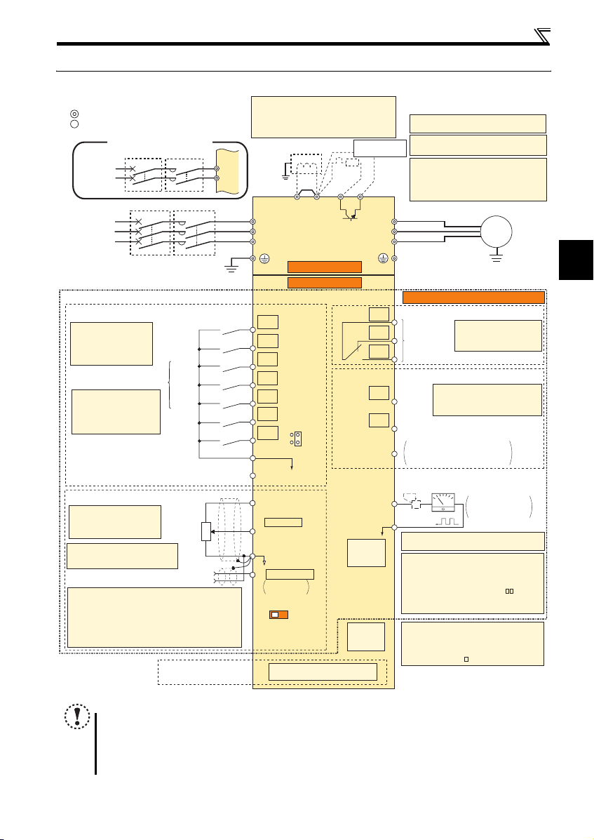
2.3 Wiring
2.3.1 Terminal connection diagram
Sink logic
Main circuit terminal
Control circuit terminal
Single-phase power input
Single-phase
AC power
supply
Three-phase
AC power
supply
Control input signals (No voltage input allowed)
Terminal functions vary
with the input terminal
assignment (Pr. 178 to
Pr. 184)
*2 When using terminals PC
and SD as a 24VDC
power supply, take care
not to short across
terminals PC and SD.
Frequency setting signals (Analog)
*3 Terminal input specifications
can be changed by analog
input specifications
switchover (Pr. 73).
*4 It is recommended to use 2W1kΩ
when the frequency setting signal
is changed frequently.
*5 Terminal input specifications can be changed by analog
input specifications switchover (Pr. 267). Set the
voltage/current input switch in the "V" position to select
voltage input (0 to 5V/0 to10V) and "I" (initial value) to
select current input (4 to 20mA).
To use terminal 4 (initial setting is current input), set "4"
in any of Pr.178 to Pr.184 (input terminal function selection)
to assign the function, and turn ON AU signal.
MCCB MC
R/L1
S/L2
MCCB MC
Earth
(Ground)
Forward
rotation start
Reverse
rotation start
High
speed
Multi-speed selection
Middle
speed
Low
speed
Output
stop
Reset
Contact input common
24VDC power supply
(Common for external power supply transistor)
3
Frequency
setting
potentiometer
1/2W1kΩ
Terminal 4 input
(Current input)
Connector for
plug-in option connection
2
*4
1
(+)
(-)
*1. DC reactor (FR-HEL)
When connecting a DC reactor, remove the
jumper across P1 and P/+.
Not available for single-phase 100V power
input model.
Jumper
P1 P/+
*1
*8
PR
*6
*7
Earth
(Ground)
R/L1
S/L2
T/L3
Main circuit
Control circuit
STF
STR
RH
RM
RL
MRS
RES
SD
PC
10(+5V)
2 0 to 5VDC
(0 to 10VDC)
5(Analog common)
4 4 to 20mADC
0 to 5VDC
0 to 10VDC
IV
Voltage/current
input switch
SOURCE
*2
Option connector
SINK
*3
*5
*5
Brake unit
(Option)
R
N/-
RUN
PU
connector
*10
USB
connector
*11
*6 Terminal P1 is not available for single-
phase 100V power input model.
*7 A brake transistor is not built-in to the 0.1K
and 0.2K.
*8 Brake resistor (FR-ABR, MRS, MYS type)
Install a thermal relay to prevent an
overheat and burnout of the brake resistor.
(The brake resistor can not be connected
to the 0.1K and 0.2K.)
U
V
W
Standard control terminal block
C
B
Relay output
(Fault output)
A
Running
FU
Frequency detection
Open collector output common
SE
Calibration resistor
FM
*9
SD
*10 Operation and parameter setting can be
*11 A personal computer and an inverter can be
Relay output
Terminal functions vary
by Pr. 192 A,B,C terminal
function selection
Open collector output
Terminal functions vary with
the output terminal assignment
(Pr. 190 and Pr. 191)
Sink/source common
Indicator
(Frequency meter, etc.)
+
-
Moving-coil type
1mA full-scale
*9 It is not necessary when calibrating the
indicator from the operation panel.
done from the parameter unit (FR-PU07)
and the enclosure surface operation panel
(FR-PA07).
(Use the option cable (FR-CB2 ).)
RS-485 communication can be utilized from
a personal computer and other devices.
connected with a USB (Ver1.1) cable.
You can perform parameter setting and
monitoring with the FR Configurator (FRSW3-SETUP-W ).
Wiring
Motor
IM
2
Earth (Ground)
NOTE
y To prevent a malfunction caus ed by noise, separate the signal c ables more than 10cm from the power cables. Also
separate the main circuit w ire of the input side and t he output side.
y After wiring, wire off cuts must not be left in the inverter.
Wire offcuts can cause an alarm, failure or malfunction. Always keep the inverter clean. When drilling mounting holes
in an enclosure etc., take ca re not to allow chips and other foreign matter to enter the inverter.
y The output of the single-phase power input model is three-phase 200V.
9
Wiring
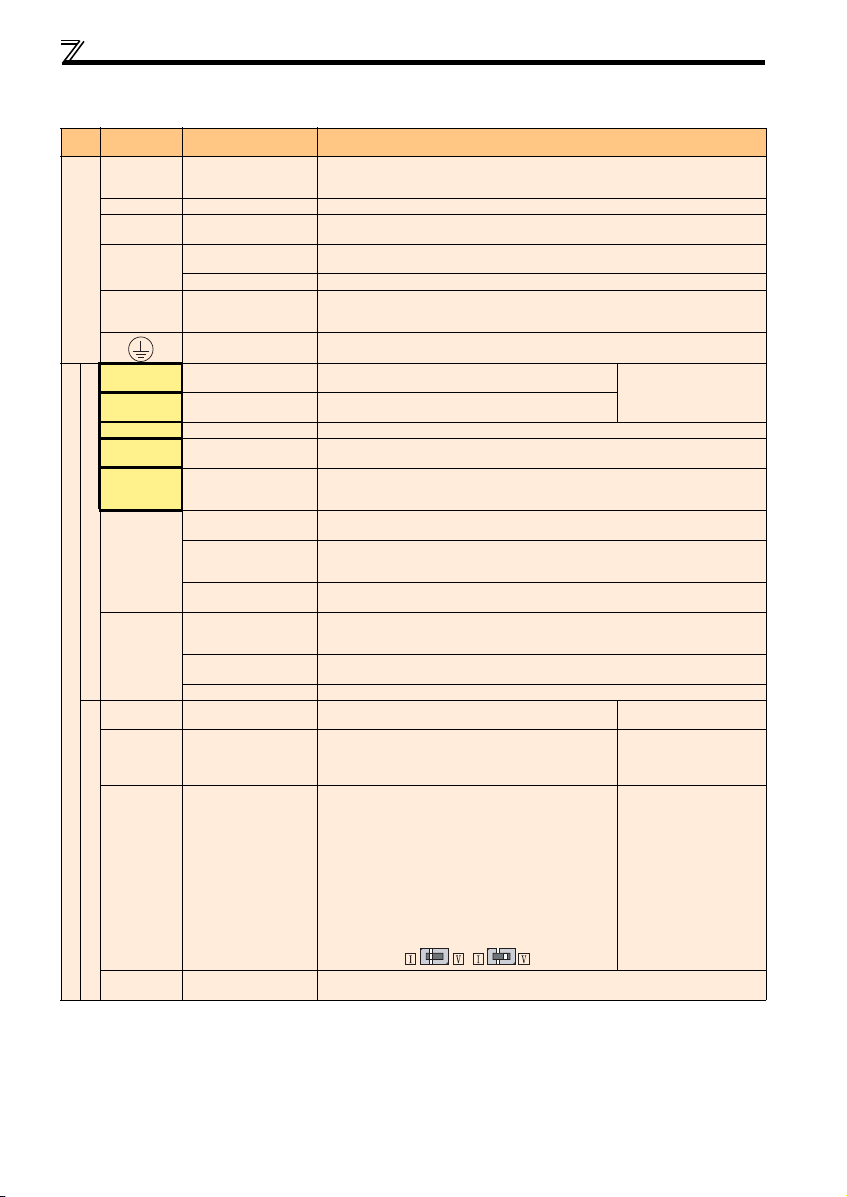
2.3.2 Terminal specifications
Ter mina l
Typ e
Symbol
R/L1, S/L2,
T/L3 *
U, V, W Inverter output Connect a three-phase squirrel-cage motor.
P/+, PR Brake resistor conn ection
P/+, N/-
Main circuit
P/+, P1 * DC reactor connection
STF Forward rotation start
STR Reverse rotation start
RH, RM, RL Mu lti-speed selection
MRS Output stop
RES Reset
SD
Contact input
PC
10
Control circuit/input signal
2
4
Frequency setting
Term inal Na me Description
AC power input
Brake unit connection
DC power input
Earth (Ground) For earthing (grounding) the inverter chassis. Must be earthed (grounded).
Contact input common
(sink) (initial setting)
External transistor
common (source)
24VDC power supply
common
External transistor
common
(sink) (initial setting)
Contact input common
(source)
24VDC power supply Can be used as 24VDC 0.1A power supply.
Frequency setting power
supply
Frequency setting
(voltage)
Frequency setting
(current)
Connect to the commercial power supply. Keep these terminals open when using the high
power factor converter (FR-HC) or power regeneration common converter (FR-CV).
∗ When using single-phase power input, terminals are R/L1 and S/L2.
Connect a brake resistor (MRS type, MYS type, FR-ABR) across terminals P/+ and PR.
(The brake resistor can not be connected to the 0.1K or 0.2K)
Connect the brake unit (FR-BU2), power regeneration common converter (FR-CV) or high
power factor converter (FR-HC).
Connect t he plus sid e of the pow er supply t o terminal P/+ and mi nus side to t erminal N/-.
Remove the jumper across terminals P/+ and P1 and connect a DC reactor. Single-phase
100V power input model is not compatible with DC reactor.
∗ Terminal P1 is not available for single-phase 100V power input model.
Turn ON the STF signal to start forward rotation and turn it OFF
to stop.
Turn ON the STR signal to start reverse rotation and turn it OFF
to stop.
Multi-speed can be selected according to the combination of RH, RM and RL signals.
Turn ON the MRS signal (20ms or more) to stop the inverter output.
Use to shut off the inverter output when stopping the motor by electromagnetic brake.
Used to reset alarm output provided when protective circuit is activated. Turn ON the RES
signal for more t han 0.1s, then turn it OFF. Initial setting is for reset always. By setting Pr. 75,
reset can be set to enabled only at fault occurrence. Recover about 1s after reset is cancelled.
Common terminal for contact input terminal (sink logic) and terminal FM.
Connect this terminal to the power supply common terminal of a transistor output (open
collector output) device, such as a programmable controller, in the source logic to avoid
malfunction by undesirable current.
Common output terminal for 24VDC 0.1A power supply (PC terminal).
Isolated from terminals 5 and SE.
Connect this terminal to the power supply common terminal of a transistor output (open
collector output) device, such as a programmable controller, in the sink logic to avoid
malfunction by undesirable current.
Common terminal for contact input terminal (source logic).
Used as power supply when connecting potentiometer for
frequency setting (speed setting) from outside of the inverter.
Inputting 0 to 5VDC (or 0 to 10V) provides the maximum output
frequency at 5V (10V) and makes input and output
proportional. Use Pr. 73 to switch between input 0 to 5VDC
(initial setting) and 0 to 10VDC input.
Inputting 0 to 20mADC (or 0 to 5V / 0 to 10V) provides the
maximum output frequency at 20mA and makes input and
output proportional. This input signal is valid only when the AU
signal is ON (terminal 2 input is invalid). To use terminal 4
(initial setting is current input), set "4" to any of Pr.178 to Pr.184
(input terminal function selection), an d turn AU signal ON. Use
Pr. 267 to switch among input 4 to 20mA (initial setting), 0 to
5VDC, and 0 to 10VDC. Set the voltage/current input switch in
the "V" position to select voltage input (0 to 5V/0 to 10V).
Current input
(initial status)
Voltage input
When the STF and STR
signals are turned ON
simultaneously, the stop
command i s given.
5VDC
permissible load current 10 mA
Input resistance 10kΩ ± 1kΩ
Permissible maximum voltage
20VDC
Voltage input:
Input resistance 10kΩ ± 1kΩ
Permissible maximum voltage
20VDC
Current input:
Input resistance 233Ω ± 5Ω
Maximum permissible current
30mA.
10
5
Frequency setting
common
Common terminal for the frequency setting signals (terminals 2 and 4). Do not earth (ground).
Wiring
r
Term ina l
Typ e
Control circuit/output sign al
Symbol
A, B, C
Relay
RUN Inverter running
FU Frequency detection
Open collector
SE
FM For meter
Pulse
— PU co nnector
— USB connector
Communication
Terminal Name Description
Relay output
(fault output)
Open collector
output common
1 changeover contact output indicates that the inverter fault occurs.
Fault: discontinuity across B-C (continuity across A-C), Normal: continuity across B-C
(discontinuity across A-C) Contact capacity 230VAC 0.3A (power factor = 0.4) 30VDC 0.3A
Switched Low when the inverter output frequency is equal to or
higher than the starting frequency (initial value 0.5Hz).
Switched High during stop or DC injection brake operation.∗
Switched Low when the inverter output frequency is equal to or
higher than the preset detected frequency and High when less
than the pr eset detect ed frequen cy.∗
Common terminal of terminal RUN and FU.
Used to output a selected monitored item (such as Output
frequency) among several monitored items. (Not output during
inverter reset.) The output signal is proportional to the
magnitude of the corresponding monitoring item.
With the PU connector, RS-485 communication can be established.
· Conforming standard: EIA-485 (RS-485) · Transmission format: Multi-drop link
· Communication speed: 4800 to 38400bps · Overall extension: 500m
FR Configurator can be operated by connecting the inverter to the personal computer through USB.
· Interface: conforms to USB1.1 · Transmission Speed: 12Mbps
· Connector: USB mini B connector (receptacle mini B type)
Permissible load 24VDC
(Maximum 27VDC) 0.1A
(a voltage drop is 3.4V
maximum when the signal is
on)
∗ Low is when the open
collector output transistor is
ON (conducts). High is when
the transistor is OFF (does
not conduct).
Permissible load current 1mA
1440 pulses/s at 60Hz
Note
y Set Pr. 267 and a voltage/current input switch correctly, then input an analog signal in accordance with the setting.
Applying a voltage with voltage/current input switch in "I" position (current input is selected) or a current with switch
in "V" position (voltage input is selected) could cause component damage of the inverter or analog circuit of output
devices.
y The inverter will b e damaged if power is applied to t he inverter output terminals (U, V, W). Never perform such wiring.
y indicates that terminal functions can be selected using Pr. 178 to Pr. 184 and Pr. 190 to Pr. 192 (I/O terminal function
selection).
y Terminal names and termina l functions are those of t he factory set.
y When connecting the DC power supply, be sure to connect the plus side of the power supply to terminal P/+ and
minus side to terminal N/-. Opposite polarity will damage the inverter.
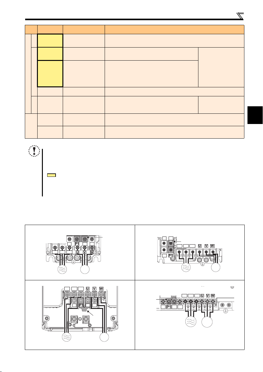
2.3.3 Terminal arrangement of the main circuit terminal, power supply and the motor wiring
Three-phase 200V/400V class
FR-E720-0.1K to 0.75K FR-E720-1.5K to 3.7K
Jumpe
N/-
P/+ PR
R/L1 S/L2 T/L3
FR-E740-0.4K to 3.7K
N/-
PR
P/+
Jumper
R/L1 S/L2 T/L3
2
IM
MotorPower supply
FR-E720-5.5K, 7.5K FR-E740-5.5K, 7.5K
R/L1 S/L2 T/L3
N/-
P/+
PR
Jumper
Jumper
N/-
IM
Power supply
Motor
Power supply
R/L1 S/L2 T/L3
P/+
PR
IM
Motor
IM
MotorPower supply
11
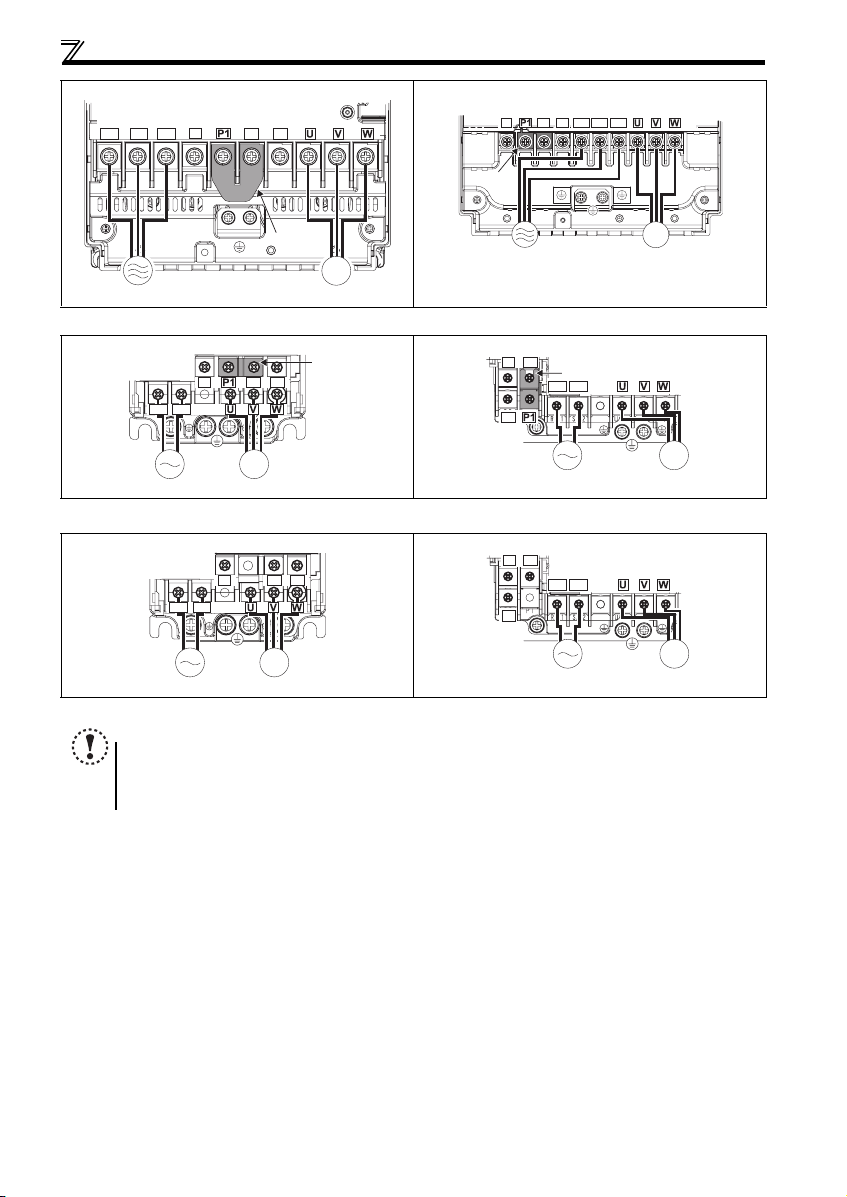
Wiring
r
FR-E720-11K, 15K FR-E740-11K, 15K
R/L1 S/L2 T/L3
N/-
P/+
PR
Jumper
N/-
P/+
R/L1 S/L2 T/L3
PR
Jumper
Power supply
IM
MotorPower supply
Single-phase 200V class
FR-E720S-0.1K to 0.4K FR-E720S-0.75K to 2.2 K
N/-
PR
R/L1 S/L2
N/-
P/+ PR
Jumpe
IM
MotorPower supply
Single-phase 100V class
FR-E710W-0.1K to 0.4K FR-E710W-0.75K
N/-
N/-
P/+ PR
R/L1 S/L2
PR
IM
MotorPower supply
NOTE
y Make sure the power cables are connected to the R/L1, S/L2, and T/L3. (Phase need not be matched.) Never connect
the power cables to the U, V, and W of the inverter. Doing so will damage the inverter.
y Connect the motor to U, V, and W. Turning ON the forward rotation switch (signal) at this time rotates the motor
counterclockwise when viewed from the load shaft.
P/+
R/L1 S/L2
Power supply
P/+
R/L1 S/L2
Power supply
IM
Motor
Jumper
IM
Motor
IM
Motor
12
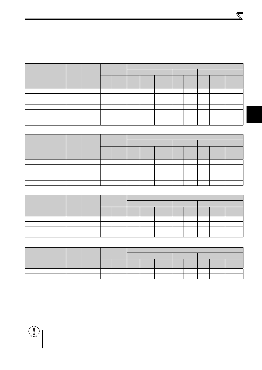
Wiring
(1) Cable size and other specifications of the main circuit terminals and the earthing terminal
Select the recommended cable size to ensure that a voltage drop will be 2% at maximum.
If the wiring distance is long between the inverter and motor, a main circuit cable voltage drop will cause the motor torque to
decrease especially at the output of a low frequency.
The following table indicates a selection example for the wiring length of 20m.
Three-phase 200V class (when input power supply is 220V)
cable
cable
cable
cable
Cable Size
AWG ∗2
R/L1
S/L2
U, V, W
T/L3
Cable Size
AWG ∗2
R/L1
S/L2
U, V, W
T/L3
Cable Size
AWG ∗2
R/L1
U, V, W
S/L2
Cable Size
AWG ∗2
R/L1
U, V, W
S/L2
PVC Cables, etc. (mm2) ∗3
R/L1
S/L2
T/L3
U, V, W
Earthing
cable
PVC Cables, etc. (mm2) ∗3
R/L1
S/L2
T/L3
U, V, W
Earthing
cable
PVC Cables, etc. (mm2) ∗3
R/L1
S/L2
U, V, W
Earthing
cable
PVC Cables, etc. (mm2) ∗3
R/L1
S/L2
U, V, W
Earthing
cable
Crimping
Ter mi nal
Applicable Inverter
Model
FR-E720-0.1K to 0.75K M3.5 1.2 2-3.5 2-3.5 2 2 2 14 1 4 2.5 2.5 2.5
FR-E720-1.5K, 2.2 K M4 1 .5 2-4 2-4 2 2 2 14 14 2.5 2 .5 2.5
FR-E720-3.7K M4 1.5 5 .5-4 5.5-4 3 .5 3.5 3.5 12 1 2 4 4 4
FR-E720-5.5K M5 2.5 5 .5-5 5.5-5 5 .5 5.5 5.5 10 1 0 6 6 6
FR-E720-7.5K M5 2.5 14-5 8-5 14 8 5.5 6 8 16 10 6
FR-E720-11K M5 2 .5 14-5 14-5 14 14 14 6 6 16 16 16
FR-E720-15K M 6(M5) 4.4 22-6 22-6 22 22 14 4 4 25 25 16
Screw
Size ∗4
Tightening
Torque
N·m
Terminal
R/L1
S/L2
T/L3
HIV Cables, etc. (mm2) ∗1
R/L1
U, V, W
S/L2
T/L3
U, V, W
Earthing
Three-phase 400V class (when input power supply is 440V)
Crimping
Ter mi nal
Applicable Inverter
Model
FR-E740-0.4K to 3.7K M4 1.5 2-4 2-4 2 2 2 14 14 2.5 2.5 2.5
FR-E740-5.5K M4 1.5 5 .5-4 2-4 3.5 2 3 .5 12 14 4 2.5 4
FR-E740-7.5K M4 1.5 5 .5-4 5.5-4 3 .5 3.5 3.5 12 1 2 4 4 4
FR-E740-11K M4 1.5 5 .5-4 5.5-4 5 .5 5.5 8 10 10 6 6 10
FR-E740-15K M5 2 .5 8-5 8-5 8 8 8 8 8 10 10 10
Screw
Size ∗4
Tightening
Torque
N·m
Terminal
R/L1
S/L2
T/L3
HIV Cables, etc. (mm2) ∗1
R/L1
U, V, W
S/L2
T/L3
U, V, W
Earthing
Single-phase 200V class (when input power supply is 220V)
N·m
Crimping
Terminal
R/L1
S/L2
HIV Cables, etc. (mm2) ∗1
R/L1
U, V, W
S/L2
U, V, W
Earthing
Ter mi nal
Applicable Inverter
Model
FR-E720S-0.1K to 0.4K M3.5 1.2 2-3.5 2-3.5 2 2 2 14 14 2.5 2.5 2.5
FR-E720S-0.75K M4 1.5 2-4 2-4 2 2 2 14 14 2.5 2.5 2.5
FR-E720S-1.5K M4 1.5 2-4 2-4 2 2 2 14 1 4 2.5 2.5 2 .5
FR-E720S-2.2K M4 1.5 5.5-4 2-4 3.5 2 2 12 14 4 2.5 2.5
Screw
Size ∗4
Tightening
Torque
Single-phase 100V class (when input power supply is 100V)
N·m
Crimping
Terminal
R/L1
S/L2
HIV Cables, etc. (mm2) ∗1
R/L1
U, V, W
S/L2
U, V, W
Earthing
Ter mi nal
Applicable Inverter
Model
FR-E710W-0.1K to 0.4K M3 .5 1.2 2-3.5 2-3.5 2 2 2 14 14 2.5 2.5 2.5
FR-E710W-0.75K M4 1 .5 5.5-4 2-4 3 .5 2 2 14 14 2 .5 2 .5 2.5
∗1
The cable size is that of the cable (HIV cable (600V class 2 vinyl-insulated cable) etc.) with continuous maximum permissible temperature of 75°C. Ass umes
that the surrounding air temperature is 50°C or less and the wiring distance is 20m or less.
∗2
The recommended cable size is that of the cable (THHW cable) with continuous maximum permissible temperature of 75°C. Assumes that the surrounding air
temperature is 40°C or less and the wiring distance is 20m or less. (Selection example for use mainly in the United States.)
∗3
The recommended cable size is that of the cable (PVC cable) with continuous maximum permissible temperature of 70°C. Assumes that the surrounding air
temperature is 40°C or less and the wiring distance is 20m or less. (Selection example for use mainly in Europe.)
∗4
The terminal screw size indicates the terminal size for R/L1, S/L2, T/L3, U, V, W, and a screw for earthing (grounding).
A screw for earthing (grounding) of the FR-E720-15K is indicated in ( ).
For single-phase power input, the terminal screw size indicates the size of terminal screw for R/L1, S/L2, U, V, W, PR, P/+, N/-, P1 and a screw for earthing
(grounding).
Screw
Size ∗4
Tightening
Torque
NOTE
y Tighten the terminal screw to the specified torque. A screw that has been tighten too loosely c an cause a short circuit
or malfunction. A screw that has been tighten too tightly can cause a short circuit or malfunction due to the unit
breakage.
y Use crimping terminals with insulation sleeve to wire the power supply and motor.
2
13
Wiring
The line voltage drop can be calculated by the following formula:
Line voltage drop [V]=
Use a larger diameter cable when the wiring distance is long or when it is desired to decrease the voltage drop (torque
reduction) in the low speed range.
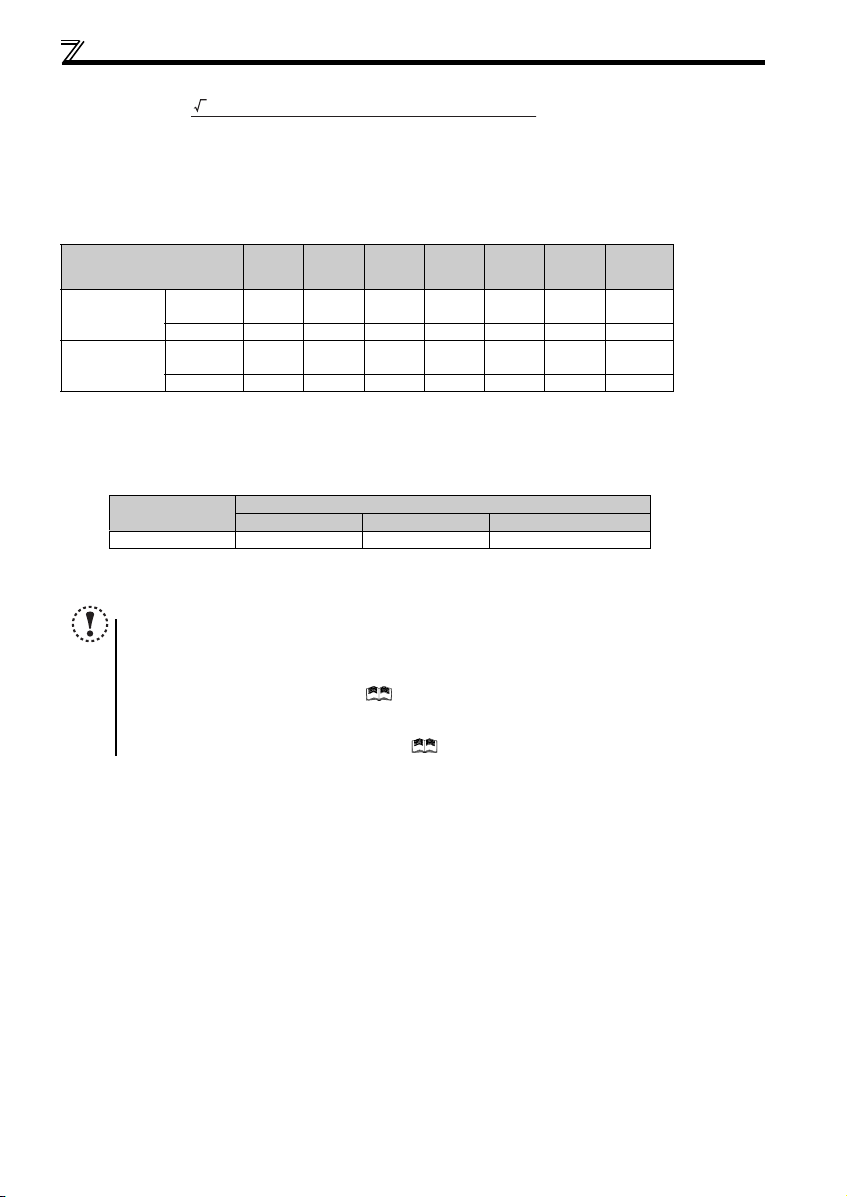
(2) Total wiring length
The overall wiring length for connection of a single motor or multiple motors sh ould be within the value in the table below.
Pr. 72 PWM frequency selection
(2kHz to 14.5kHz)
Setting
(carrier frequency)
1 (1kHz) or less
2 to15
When driving a 400V class motor by the inverter, surge voltages attributable to the wiring constants may occur at the
motor terminals, deteriorating the insulation of the motor. Take the following measures 1) or 2) in this case.
1) Use a "400V class inverter-driven insulation-enhanced motor" and set frequency in Pr. 72 PWM frequency selection
according to wiring length.
Carrier frequency 14.5kHz or less 8kHz or less 2kHz or less
2) Connect the surge voltage su ppression filter (FR-ASF- H/FR-BMF-H) o n the inverter output side.
NOTE
y Especially for long-distance wiring, the inverter may be affected by a charging current caused by the stray
capacitances of the wiring, leading to a malfunction of the overcurrent protective function, fast response current limit
function, or stall prevention function or a malfunction or fault of the equipment connected on the inverter output side.
If malfunction of fast-response current limit function occurs, disable this function. If malfunction of stall prevention
function occurs, incre ase the stall level. ( Refer to Pr. 22 Stall prevention operation level and Pr. 156 Stall prevention
operation selection in Chapter 4 of the Instruction Manual (Applied))
y When using the automatic restart after instantaneous power failure function with the wiring length exceeding 100m,
select without frequen cy search (Pr. 162 = "1, 11"). (
3 × wire resistance[mΩ/m] × wiring distance[m] × current[A]
1000
0.1K 0.2K 0.4K 0.75K 1.5K 2.2K
100V class,
200V class
400V class - - 200m 20 0m 300m 500m 500m
100V class,
200V class
400V class - - 30m 100m 200m 300m 500m
200m 200m 300m 500m 50 0m 500m 500m
30m 100m 200m 300m 500m 500m 500m
Wiring Length
50m or less 50m to 100m Exceeding 100m
Refer to Chapter 4 of the Instruction Manu al (Applied))
3.7K
or Higher
14
 Loading...