

Mitsubishi Electric FR-E700, FR-E720-0.1K, FR-E740-0.4K, FR-E720S-0.1K, FR-E710W-0.1K Basic Instruction Manual

INVERTER
FR-E700
INSTRUCTION MANUAL (BASIC)
FR-E720-0.1K to 15K
FR-E740-0.4K to 15K
FR-E720S-0.1K to 2.2K
FR-E710W-0.1K to 0.75K
Thank you for choosing this Mitsubishi Inverter.
This Instruction Manual (basic) is intended for users who "just want to run the inverter".
If you are going to utilize functions and performance, refer to the Instruction Manual (applied) [IB-0600277ENG]. The
Instruction Manual (applied) is separately available from where you purchased the inverter or your Mitsubishi sales
representa tive.
CONTENTS
1
PRODUCT CHECKING AND PARTS IDENTIFICATION ............................. 1
INSTALLATION AND WIRING ..................................................................... 2
2
2.1 Peripheral devices..................................................................................................... 3
2.2 Removal and reinstallation of the cover.................................................................... 4
2.3 Installation of the inverter and instructions ............................................................... 7
2.4 Wiring ........................................................................................................................ 9
2.5 When using the brake resistor (MRS type, MYS type, FR-ABR) ...........................26
2.6 Power-OFF and magnetic contactor (MC).............................................................. 27
2.7 Precautions for use of the inverter .......................................................................... 28
2.8 Failsafe of the system which uses the inverter ....................................................... 30
3
DRIVE THE MOTOR ................................................................................... 31
3.1 Step of operation..................................................................................................... 31
3.2 Operation panel....................................................................................................... 32
3.3 Before operation...................................................................................................... 40
3.4 Start/stop from the operation panel (PU operation)................................................ 55
3.5 Make a start and stop with terminals (external operation)...................................... 61
3.6 Parameter list .......................................................................................................... 71
4
TROUBLESHOOTING ................................................................................ 96
4.1 Reset method of protective function ....................................................................... 96
4.2 List of fault or alarm indications .............................................................................. 97
4.3 Causes and corrective actions................................................................................ 98
4.4 Correspondences between digital and actual characters..................................... 107
4.5 Check and clear of the faults history..................................................................... 108
4.6 Check first when you have some troubles ............................................................ 110
5
PRECAUTIONS FOR MAINTENANCE AND INSPECTION..................... 117
5.1 Inspection items .................................................................................................... 117
6
SPECIFICATIONS..................................................................................... 125
6.1 Rating .................................................................................................................... 125
6.2 Common specifications......................................................................................... 127
6.3 Outline dimension drawings.................................................................................. 128
APPENDIX................................................................................................. 133
700
1
2
3
4
5
6
This instruction manual (basic) provides handling information and precautions for use of the equipment.
G
Please forward this instruction manual (basic) to the end user.
This section is specifically about safety matters
Do not attempt to install, operate, maintain or inspect the
inverter until you have read through the Instruction Manual
(basic) and appended documents carefully and can use the
equipment correctly. Do not use this product until you have
a full knowledge of the equipment, safety in formation and
instructions.
In this Instruction Manual (bas ic), the safety instruction
levels are classified into "WARNING" and "CAUTION" .
WARNING
CAUTION
Note that even the level may lead to a serious
consequence according to conditions. Please follow the
instructions of both le vels because they are important to
personnel safety.
Assumes that incorrect handli ng may
cause hazardous conditions, resulting
in death or severe injur y.
Assumes that incorrect handli ng may
cause hazardous conditions, resulting
in medium or slight injury, or may
cause physical damage only.
CAUTION
1. Electric Shock Prevention
WARNIN
z
While power is ON or
open the front cover. Otherwise you may g et an electric
shock.
z Do not run the inverter with the front cover or wiring cover
removed. Otherwise, yo u may access the exposed highvoltage terminals or the charging part of the circuitry and
get an electric shock.
z Even if power is OFF, do not remove the front cover
except for wirin g or periodic insp ection. You may access
the charged inver ter circuits and get an el ectric shock.
z Before starting wiring or inspection, switch OFF power,
check to make sure that the operation panel indicator is
OFF, wait for at least 10 minutes after the power supply
has been switched OFF, and check that there are no
residual voltage using a tester or the like. The capacitor is
charged with high voltage for some time after power OFF
and it is dangerous.
z This inverter must be earthed (grounded). Earthing
(grounding) must conform to the requirements of national
and local safety regulations and electrical code. (NEC
section 250, IEC 536 class 1 and other applicable
standards)
Use an neutral-point earthed (grounded) power supply for
400V class inverte r in compliance with EN standard.
z Any person who is involved in the wiring or inspection of
this equipment should be fully competent to do the work.
z Always install the inverter be fore wiring. Otherwise, yo u
may get an electric s hock or be injured.
z Perform setting dial and key operations with dry hands to
prevent an electric shoc k. Otherwise you may get an
electric shock.
z Do not subject the c ables to scratches, excessive stress,
heavy loads or pinching. Otherwise, you may get an
electric shock.
z Do not change the cooling fan while power is ON. It is
dangerous to change the cooling fan while power is ON.
z Do not touch the printed circuit board with wet hands.
Otherwise, you may ge t an electric shock.
z When measuring t he main circuit capaci tor capacity, the
DC voltage is applied to t he motor for 1s at powering OFF.
Never touch the motor terminal, etc. right after powering
OFF to prevent an e lectric shock.
when the inverter is running, do not
2. Fire Prevention
CAUTION
Install the inverter on a nonflammable wall without holes
z
(so that nobody can touch the inverter heatsink on the rear
side, etc.). Mounting it to or near flammable ma terial can
cause a fire.
z If the inverter ha s become faulty, switch OF F the inverter
power. A continuous flow of large current could cause a
fire.
z When using a brake resist or, make up a sequence that will
turn OFF power when an alarm signal is output.
Otherwise, the brake re sistor may excessive ly overheat
due to damage of the brake transistor and such, causing a
fire.
z Do not connect a resi stor directly to the DC t erminals P/+
and N/-. This could cause a fire.
A-1
3.Injury Prevention
G
CAUTION
z Apply only the voltage speci fied in the instructio n manual
to each terminal. Otherwise, burst, damage, etc. may
occur.
z Ensure that the cab les are connected to the correct
terminals. Otherwise , burst, damage, etc. ma y occur.
z Always make sure that polarity is correct to pr event
damage, etc. Otherwise, burst, damage, etc. may occur.
z While power is ON or for some time after power-OFF, do
not touch the inver ter as they will be ext remely hot. Doing
so can cause burns.
4. Additional Instructions
Also note the following points to pre vent an accidental failure,
injury, electric shock, etc.
(1) Transportation and mounting
CAUTION
z Transport the product using the correct method that
corresponds to the weight. Failure to observe this could
lead to injuries.
z Do not stack the inverter boxes high er than the number
recommended.
z Ensure that installation positi on and material can
withstand the weight of the inverter. Install according to
the information in th e instruction manual.
z Do not install or operate the inverter if it is damaged or
has parts missing.
z When carrying the inverter, do not hold it by the front
cover or setting dial; it may fall off or fail.
z Do not stand or rest heavy objects on the product.
z Check the inverter mounting orientation is correct.
z Prevent other conductive bodies such as screws and
metal fragments or other flammable substance such as
oil from entering the inverter.
z As the inverter is a precision instrument, do not drop or
subject it to impact.
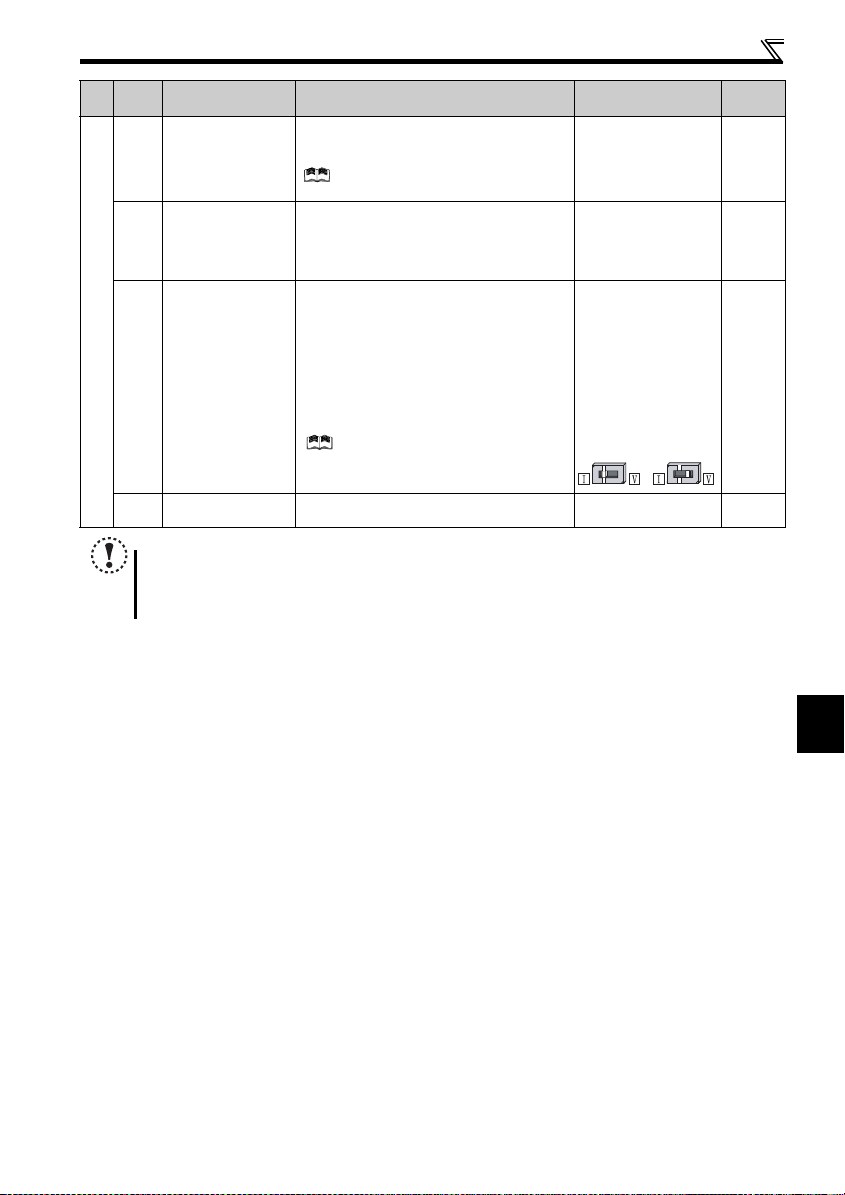
z Use the inverter under the following environmental
conditions: Otherwise, the inverter may be damaged.
Surroundi ng
air
temperature
Ambient
humidity
Storage
temperature
Atmosphere
Environment
Altitude/
vibration
∗1 Temperature appl icable for a short time, e.g. in transit.
-10°C to +50°C (non-freezing)
(-10°C to +40°C for totally-enclosed structure
feature)
90%RH or less (non-condensing)
-20°C to +65°C *1
Indoors (free from corrosi ve gas, flammable ga s,
oil mist, dust and dirt)
Maximum 1,000m above sea level.
2
or less at 10 to 55Hz (directions of X, Y, Z
5.9m/s
axes)
(2) Wiring
CAUTION
z Do not install a power fac tor correction capacitor or surge
suppressor/capacitor type filter on the inverter output
side. These devices on the inverter output side may be
overheated or burn out.
z The connection orientation of the output cables U, V, W to
the motor will affect the direction of rotation of the motor.
(3) Trial run
CAUTION
z Before starting operation, confirm and adjust the
parameters. A failure to do so may cau se some machines
to make unexpected m otions.
(4) Usage
WARNIN
z When you have chosen the retry function, stay away from
the equipment as it will restart suddenly after trip.
z Since pressing key may not stop output dependi ng
on the function setting status, provide a circuit and switch
separately to make an emerg ency stop (power OFF,
mechanical brake o peration for emergen cy stop, etc).
z Make sure that the start signal is OFF befor e resetting the
inverter alarm. A failure to do so may restart the motor
suddenly.
z
The load used should be a three-phase induction motor only.
Connection of any other electrical equipment to the
inverter output may damage the equipment.
z Do not modify the equipment.
z
Do not perform parts removal which is not i nstructed in this
manual. Doing so may lead to fault or damage of the product.
CAUTION
z
The electronic thermal relay function does not guarantee
protection of the motor from overheati ng. It is recommende d
to install both an external thermal and PTC thermistor for
overheat protection.
z Do not use a magnetic contactor on the inverter input for
frequent starting/stopping of the inverter. Otherwise, the
life of the invert er decreases.
z Use a noise filter to re duce the effect of elec tromagnetic
interference. Oth erwise nearby electron ic equipment may
be affected.
z Take measures to suppress harmonics. Otherwise power
supply harmonics from the inverter may heat/damage the
power factor correction capacitor and generator.
z When a 400V clas s motor is inverter -driven, please use an
insulation-enhanced motor or measures taken to
suppress surge voltages. Surge v oltages attributable to
the wiring constants may occur at the motor terminals,
deteriorating the insulation of the motor.
z When parameter clear or all parameter clear i s performed,
reset the required parameters before starting operations.
Each parameter return s to the initial value.
z The inverter can be easily set for high-speed operation.
Before changing its setting, f ully examine the
performances of the motor and machine.
z In addition to the inverter’s holding function, install a
holding device to ensure safety.
z Before running an inverter which had been stored for a
long period, always perform inspection and test
operation.
z For prevention of damage due to static electricity, touch
nearby metal before touching this product to eliminate
static electricity from your body.
A-2
(5) Emergency stop
CAUTION
z Provide a safety back up such as an emergen cy brake
which will prevent the machine and equipment from
hazardous conditions if the inverter fails.
z When the breaker on the inverter inp ut side trips, check
for the wiring fault (short circuit), damage to internal parts
of the inverter, etc. Identify the cause of the trip, then
remove the cause and power ON the breake r.
z When any protectiv e function is activated, take the
appropriate correct ive action, then re set the inverter, and
resume operation.
(6) Maintenance, inspection and parts replacement
CAUTION
z Do not carry out a megger (insulation resistance) test on
the control circuit of the inverter. It will cause a fai lure.
(7) Disposal
CAUTION
z Treat as industrial waste.
General instruction
Many of the diagrams and dr awings in this Instruction
Manual (basic) show the inverter without a cover, or partially
open. Never operate the inverter in this manner. Always
replace the cover and follo w this Instruction Manu al (basic)
when operating the inverter.
A-3

CONTENTS
1 PRODUCT CHECKING AND PARTS IDENTIFICATION 1
2 INSTALLATION AND WIRING 2
2.1 Peripheral devices ...................................................................................................3
2.2 Removal and reinstallation of the cover ............................................................... 4
2.2.1 Front cover..................................................................................................................................... 4
2.2.2 Wiring cover................................................................................................................................... 6
2.3 Installation of the inverter and instructions .........................................................7
2.4 Wiring ....................................................................................................................... 9
2.4.1 Terminal connection diagram ........................................................................................................ 9
2.4.2 Specification of main circuit terminal ........................................................................................... 10
2.4.3 Terminal arrangement of the main circuit terminal, power supply and the motor wiring.............. 11
2.4.4 Standard control circuit terminal .................................................................................................. 16
2.4.5 Changing the control logic ........................................................................................................... 19
2.4.6 Wiring of control circuit ................................................................................................................ 21
2.4.7 Connection to the PU connector.................................................................................................. 23
2.4.8 USB connector............................................................................................................................. 25
2.5 When using the brake resistor (MRS type, MYS type, FR-ABR) .......................26
2.6 Power-OFF and magnetic contactor (MC) ...........................................................27
2.7 Precautions for use of the inverter ......................................................................28
2.8 Failsafe of the system which uses the inverter .................................................. 30
3 DRIVE THE MOTOR 31
3.1 Step of operation ...................................................................................................31
3.2 Operation panel ..................................................................................................... 32
3.2.1 Names and functions of the operation panel ............................................................................... 32
3.2.2 Basic operation (factory setting) .................................................................................................. 33
3.2.3 Easy operation mode setting (easy setting mode)....................................................................... 34
3.2.4 Operation lock (Press [MODE] for a while (2s))........................................................................... 35
3.2.5 Monitoring of output current and output voltage .......................................................................... 36
3.2.6 First priority monitor ..................................................................................................................... 36
3.2.7 Setting dial push .......................................................................................................................... 36
3.2.8 Change the parameter setting value ............................................................................................ 37
I

3.2.9 Parameter clear/all parameter clear ............................................................................................ 38
3.2.10 Initial value change list ................................................................................................................ 39
3.3 Before operation ................................................................................................... 40
3.3.1 Simple mode parameter list......................................................................................................... 40
3.3.2 Overheat protection of the motor by the inverter (Pr. 9) .............................................................. 41
3.3.3 When the rated motor frequency is 50Hz (Pr. 3) ........................................................................ 43
3.3.4 Increase the starting torque (Pr. 0) ............................................................................................. 44
3.3.5 Limit the maximum and minimum output frequency (Pr. 1, Pr. 2) ............................................... 45
3.3.6 Change acceleration and deceleration time of the motor (Pr. 7, Pr. 8) ....................................... 46
3.3.7 Selection of the start command and frequency command locations (Pr. 79) .............................. 47
3.3.8 Large starting torque and low speed torque are necessary
(Advanced magnetic flux vector control, General-purpose magnetic flux vector control)
(Pr. 71, Pr. 80, Pr. 81, Pr. 800) .................................................................................................. 48
3.3.9 To exhibit the best performance of the motor performance (offline auto tuning)
(Pr. 71, Pr. 83, Pr. 84, Pr. 96) ...................................................................................................... 51
3.4 Start/stop from the operation panel (PU operation) .......................................... 55
3.4.1 Set the set frequency to operate (example: performing operation at 30Hz)................................ 55
3.4.2 Use the setting dial like a potentiometer to perform operation. ................................................... 57
3.4.3 Use switches to give a frequency command (multi-speed setting).............................................. 58
3.4.4 Perform frequency setting by analog (voltage input)................................................................... 59
3.4.5 Perform frequency setting by analog (current input) ................................................................... 60
3.5 Make a start and stop with terminals (external operation) ............................... 61
3.5.1 Use the set frequency set by the operation panel (Pr. 79 = 3)..................................................... 61
3.5.2 Use switches to give a start command and a frequency command
(multi-speed setting) (Pr. 4 to Pr. 6) ............................................................................................ 63
3.5.3 Perform frequency setting by analog (voltage input)................................................................... 65
3.5.4 Change the frequency (60Hz) at the maximum voltage input (5V initial value)........................... 67
3.5.5 Perform frequency setting by analog (current input) ................................................................... 68
3.5.6 Change the frequency (60Hz) at the maximum current input (at 20mA, initial value) ................. 70
3.6 Parameter list ........................................................................................................ 71
3.6.1 List of parameters classified by purpose of use .......................................................................... 71
3.6.2 Parameter list .............................................................................................................................. 74
CONTENTS
4 TROUBLESHOOTING 96
4.1 Reset method of protective function .................................................................. 96
4.2 List of fault or alarm indications ......................................................................... 97
4.3 Causes and corrective actions ............................................................................ 98
II

4.4 Correspondences between digital and actual characters ............................... 107
4.5 Check and clear of the faults history ................................................................ 108
4.6 Check first when you have some troubles .......................................................110
4.6.1 Motor does not start................................................................................................................... 110
4.6.2 Motor or machine is making abnormal acoustic noise ............................................................... 112
4.6.3 Inverter generates abnormal noise............................................................................................ 112
4.6.4 Motor generates heat abnormally.............................................................................................. 112
4.6.5 Motor rotates in the opposite direction....................................................................................... 113
4.6.6 Speed greatly differs from the setting........................................................................................ 113
4.6.7 Acceleration/deceleration is not smooth .................................................................................... 113
4.6.8 Speed varies during operation................................................................................................... 114
4.6.9 Operation mode is not changed properly................................................................................... 114
4.6.10 Operation panel display is not operating ................................................................................... 115
4.6.11 Motor current is too large........................................................................................................... 115
4.6.12 Speed does not accelerate........................................................................................................ 116
4.6.13 Unable to write parameter setting .............................................................................................. 116
5 PRECAUTIONS FOR MAINTENANCE AND INSPECTION 117
5.1 Inspection items .................................................................................................. 117
5.1.1 Daily inspection.......................................................................................................................... 117
5.1.2 Periodic inspection..................................................................................................................... 117
5.1.3 Daily and periodic inspection ..................................................................................................... 118
5.1.4 Display of the life of the inverter parts ....................................................................................... 119
5.1.5 Cleaning..................................................................................................................................... 121
5.1.6 Replacement of parts................................................................................................................. 121
5.1.7 Inverter replacement.................................................................................................................. 124
6 SPECIFICATIONS 125
6.1 Rating ...................................................................................................................125
6.2 Common specifications ......................................................................................127
6.3 Outline dimension drawings .............................................................................. 128
APPENDIX 133
Appendix 1 For customers who have replaced the conventional model
with this inverter ....................................................................................... 133
III

Appendix 1-1 Replacement of the FR-E500 series ............................................................................. 133
V/F
AD
MFVC
GP
MFVC
Appendix 2 Instructions for compliance with the European Directives ................. 135
Appendix 3 Instructions for UL and cUL..................................................................... 138
<Abbreviations>
PU: Operation pan el and parameter unit (FR-PU04, FR-PU07)
Inverter: Mitsubishi inverter FR-E700 series
FR-E700: Mitsubishi inverter FR-E700 series
Pr.: Parameter number
PU operation: Op eration usin g the PU (oper ation panel/FR -PU04/FR-PU07)
External operation: Operation using the control circuit signals
Combined operation : Operation using the PU (FR-PU04/FR-PU07) and external operation
Standard motor : SF-JR
Constant torque motor : SF-HRCA
<Trademarks>
LONWORKS® is a registered trademark of Echelon Corporation in the U.S.A and other countries.
Company and product names herein are the trademarks and registered trademarks of their respective owners.
<Mark>
V/F
V/F
: Indicates functions available during V/F control
AD
MFVC
AD
MFVC
: Indicates functions available during Advanced magnetic flux vector control
GP
MFVC
GP
MFVC
: Indicates functions available during General-purpose magnetic flux vector control
REMARKS: Additional helpful contents and relations with other functions are written
Note: Contents requiring caution or cases when set functions are not activated are written.
POINT: Useful contents and points are written.
CONTENTS
IV

MEMO
V
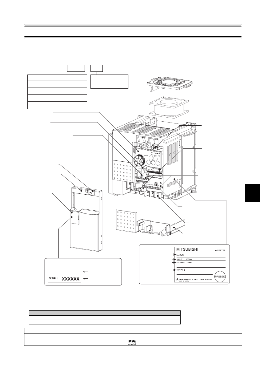
1 PRODUCT CHECKING AND PARTS IDENTIFICATION
Unpack the inverter and check the capacity plate on the front cover and the rating plate on the inverter side face to ensure that
the product agrees with your order and the inverter is intact.
zInverter type
--
E740 3.7
FR
No. Voltage class
Three-phase 200V class
E720
Three-phase 400V class
E740
Single-phase 200V class
E720S
Single-phase 100V class
E710W
Operation panel
(Refer to page 32)
PU connector
(Refer to page 18)
Voltage/current input switch
(Refer to page 16)
USB connector cover
(Refer to page 25)
Front cover
(Refer to page 4)
PU connector cover
(Refer to page 23)
Capacity plate *
FR-E740-3.7K
• Accessory
· Fan cover fixing screws (M3 × 35mm)
These screws are necessary for compliance with the European Directive (
FR-E720-1.5K to 3.7K, FR-E740-1.5K to 3.7K, FR-E720S-0.75K to 2.2K 1
Harmonic suppression guideline (when inverters are used in Japan)
All models of general -purpose inverters us ed by specific consume rs are covered by "Har monic suppression gui deline for consume rs who
receive high voltage or spe cial high voltage". (For fu rther details, refer to the chapter 3 of the Instruction Manual (applied).)
FR-E720-5.5K to 15K, FR-E740-5.5K to 15K 2
K
Represents the
inverter capacity [kW]
Cooling fan
(Refer to page 121)
Changing the control
logic jumper connector
(Refer to page 19)
Main circuit
terminal block
(Refer to page 10)
Combed shap ed wiring
cover
(Refer to page 6)
Rating plate *
Inverter type
Input rating
Output rating
Inverter type
Serial number
Serial number
* Location of the capacity plate and the rating plate differs according to the inverter capacity.
Refer to the outline dimension drawing.(Refer to page 128)
Capacity Number
FR-E740-3.7K
Refer to page 135
USB connector
(mini-B connector)
(Refer to page 18)
Connector for plug-in
option connection
(Refer to the instruction
manual of options.)
Standard control circuit
terminal block
(Refer to p age 16)
)
1
PRODUCT CHECKING AND PARTS IDENTIFICATION
1
2 INSTALLATION AND WIRING
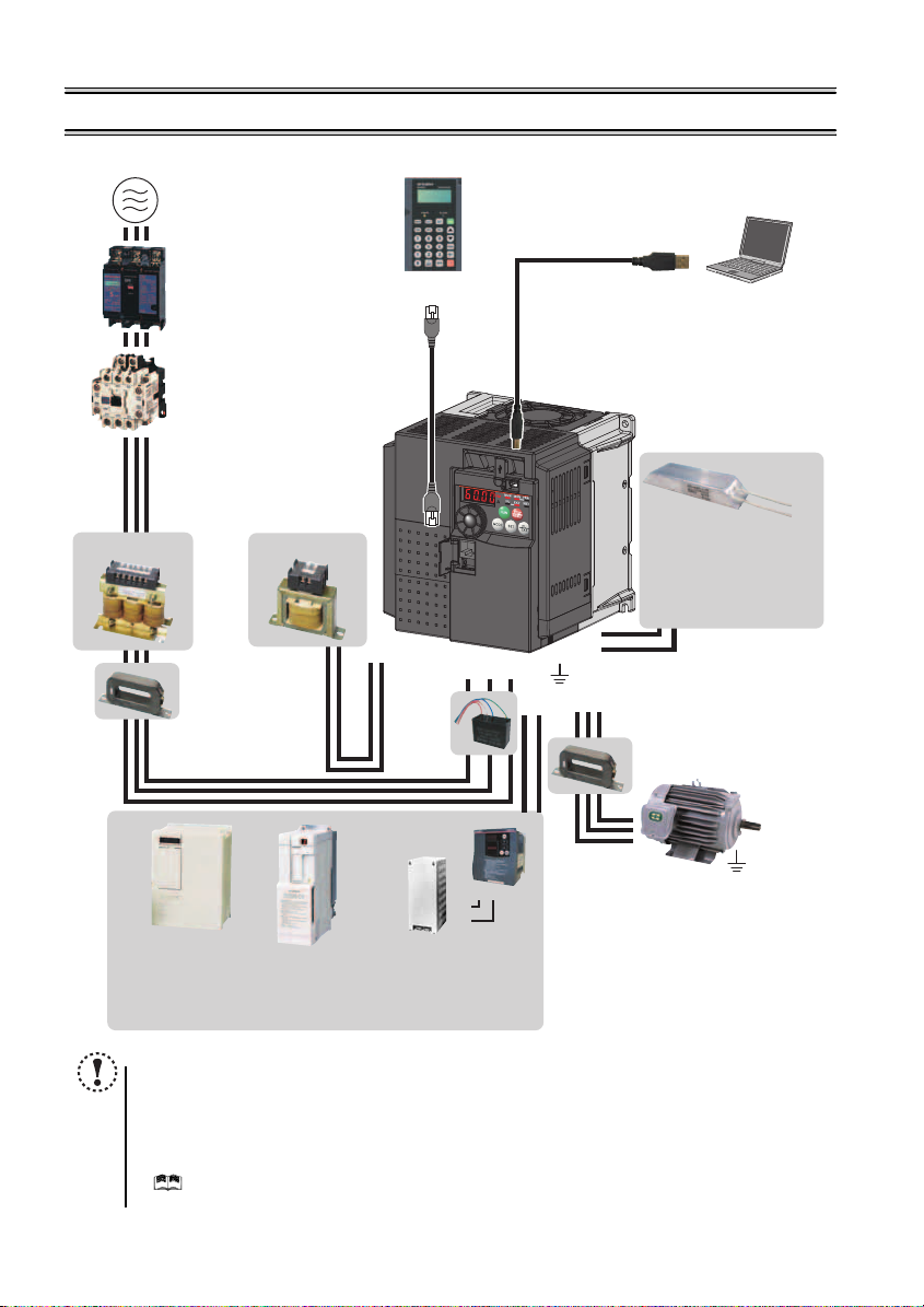
AC power supply
AC reactor (FR -HAL)
Use within the permissible power supply
specifications of the inverter. To ensure
safety, use a moulded case circuit breaker,
earth leakage circuit breaker or magnetic
contactor to switch power ON/OFF.
(Refer to page 304)
Moulded case circuit breaker
(MCCB) or earth leakage circuit
breaker (ELB), fuse
The breaker must be selected carefully
since an in-rush current flows in the
inverter at power on.
(Refer to page 3)
Magnetic contactor (MC)
Install the magnetic contactor to ensure
safety. Do not use this magnetic contactor
to start and stop the inverter. Doing so will
cause the inverter life to be shorten.
(Refer to page 3)
Reactor (FR-HAL, FR-HEL option)
Reactors (option) must be used when
power harmonics measures are taken,
the power factor is to be improved or the
inverter is installed near a large power
supply system (500kVA or more). The
inverter may be damaged if you do not
use reactors. Select the reactor according
to the model. Remove the jumpers across
terminals P/+ and P1 to connect the DC reactor.
Install a noise filter to reduce
the electromagnetic noise
generated from the inverter.
Effective in the range from
about 1MHz to 10MHz. When
more wires are passed
through, a more effective result
can be obtained. A wire should
be wound four turns or more.
DC reactor (FR-HEL)
Noise filter
(FR-BSF01, FR-BLF)
P1P/+
Capacitor type
filter
(FR-BIF)
Reduces the
radio noise.
Parameter unit (FR-PU07)
By connecting the connection cable
(FR-CB2) to the PU connector,
operation can be performed from
FR-PU07.
(Refer to page 23)
R/L1 S/L2T/L3
P/+
PR
Earth (Ground)
V
UW
N/-P/+
USB connector
A personal computer and an inverter
can be connected with a
USB (Ver1. 1) cable.
(Refer to page 25)
Inverter (FR-E700)
The life of the inverter is influe nced by
surrounding air tem perature. The
surrounding air tem perature should be as
low as possible within the permissible
range. This must be noted especi ally
when the inverter is installed in an
enclosure.
(Refer to page 7)
Wrong wiring might lead to d amage of the
inverter. The control signal lines must be
kept fully away from the main circuit to
Brake resistor
(FR-ABR, MRS type, MYS type)
Braking capabilit y can be improved.
(0.4K or more)
Always install a t hermal relay when
using a brake resist or whose capacity
is 11K or more.
Noise filter
(FR-BSF01, FR-BLF)
Install a noise filter to reduce the
electromagnetic noise generated
from the inverter.
Effective in the range from about
1MHz to 10MHz. A wire should be
wound four turns at a maximum.
(Refer to page 26)
Motor
High power factor
converter (FR-HC)
Power supply harmonics
can be greatly suppressed.
Install this as required.
2
Brake unit
(FR-BU2)
Earth (Ground)
Power regeneration
common converter
(FR-CV)
Great braking capability
is obtained.
Install this as required.
PR
P/+
P/+
PR
Resistor unit (FR-BR)
Discharging resistor (GZG, GRZG)
The regenerative braking capability
of the inverter can be exhibited fully.
Install this as required.
Devices connected to the output
Do not install a power factor correction capacitor,
surge suppressor or capacitor type filter on the output
side of the inverter. When installing a moulded case
circuit breaker on the output side of the inverter,
contact each manufacturer for selection of the
moulded case circuit breaker.
Earth (Ground)
To prevent an electric shock, always earth (ground)
the motor and inverter. For reduction of induction noise
from the power line of the inverter, it is recommended
to wire the earth (ground) cable by returning it to the
earth (ground) terminal of the inverter.
NOTE
Do not install a power factor correction capacitor, surge suppressor or capacitor type filter on the inverter output
side. This will cause the inverter to trip or the capacitor and surge suppressor to be damaged. If any of the above
devices are connected, immediate ly remove them.
Electrom agnetic wave interf erence
The input/output (main circuit) of the inverter includes high frequency components, which may interfere with the
communication devic es (such as AM radio s) used near the inv erter. In this case, install the FR- BIF optional capacitor
type filter (for use in the input side only) or FR-BSF01 or FR-BLF common mode filter to minimize interference.
( Refer to the chapter 3 of the Instr uction Manual (applied)).
Refer to the instruction manual of each option and peripheral devices for details of peripheral devices.
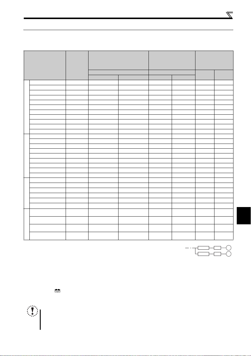
Peripheral devices
2.1 Peripheral devices
Check the inverter type of the inverter you purchased. Appropriate peripheral devices must be selected according to the capacity.
Refer to the following list and prepare appropriate peripheral devices:
Moulded Case Circuit Breaker
(MCCB) ∗1
(ELB) ∗2
Reactor connection Reactor connection
Inverter Type
Motor
Output
(kW)
or Earth Leakage Circuit Breaker
without with without with
FR-E720-0.1K 0.1 30A F 5A 30AF 5A S-N10 S-N10 0.4K ∗5 0.4K ∗5
FR-E720-0.2K 0.2 30A F 5A 30AF 5A S-N10 S-N10 0.4K
FR-E720-0.4K 0.4 30A F 5A 30AF 5A S-N10 S-N10 0.4K 0.4K
FR-E720-0.75K 0.75 30AF 10A 30AF 10A S-N10 S-N10 0.75K 0.75K
FR-E720-1.5K 1.5 30AF 15A 30AF 1 5A S-N10 S-N10 1.5K 1.5K
FR-E720-2.2K 2.2 30AF 20A 30AF 1 5A S-N10 S-N10 2.2K 2.2K
FR-E720-3.7K 3.7 30AF 30A 30AF 3 0A S-N20, S-N21 S-N10 3.7K 3.7K
FR-E720-5.5K 5.5 50AF 50A 50AF 4 0A S-N25 S-N20, S-N21 5.5K 5.5K
Three-Phase 200V
FR-E720-7.5K 7.5 100AF 60A 50AF 50A S-N25 S-N25 7.5K 7.5K
FR-E720-11K 11 100AF 75A 100AF 75A S-N35 S-N35 11K 11K
FR-E720-15K 15 225 AF 125A 100AF 100A S- N50 S-N50 15K 15K
FR-E740-0.4K 0.4 30A F 5A 30AF 5A S-N10 S-N10 H0. 4K H0.4K
FR-E740-0.75K 0.75 30AF 5A 30A F 5A S-N10 S-N10 H0.7 5K H0.75K
FR-E740-1.5K 1.5 30AF 10A 30AF 1 0A S-N10 S-N10 H1.5K H1.5K
FR-E740-2.2K 2.2 30AF 15A 30AF 1 0A S-N10 S-N10 H2.2K H2.2K
FR-E740-3.7K 3.7 30AF 20A 30AF 1 5A S-N10 S-N10 H3.7K H3.7K
FR-E740-5.5K 5.5 30AF 30A 30AF 2 0A S-N20, S-N21 S-N11, S-N12 H5.5K H5.5K
FR-E740-7.5K 7.5 30AF 30A 30AF 3 0A S-N20, S-N21 S-N20, S-N21 H7.5K H7.5K
Three-Phase 400V
FR-E740-11K 11 50AF 50A 50AF 40A S-N20, S-N21 S-N20, S-N21 H11K H11K
FR-E740-15K 15 100AF 60A 50AF 50A S-N25 S-N20, S-N21 H15K H15K
FR-E720S-0.1K 0.1 30A F 5A 30AF 5A S-N10 S-N10
FR-E720S-0.2K 0.2 30A F 5A 30AF 5A S-N10 S-N10
FR-E720S-0.4K 0.4 30AF 10A 30AF 1 0A S-N10 S-N10
FR-E720S-0.75K 0.75 30AF 15 A 30AF 10A S-N10 S-N10
FR-E720S-1.5K 1.5 30AF 20A 30AF 2 0A S-N10 S-N10
FR-E720S-2.2K 2.2 30AF 40A 30AF 3 0A S-N20, S-N21 S-N10
Single-Phase 200V
FR-E710W-0.1K 0.1 30AF 10A 30AF 5A S-N10 S-N10
FR-E710W-0.2K 0.2 30AF 10A 30AF 10A S-N10 S-N10
FR-E710W-0.4K 0.4 30AF 15A 30AF 15A S-N10 S-N10
FR-E710W-0.75K 0.75 30AF 30A 30AF 20A S-N10 S-N10
Single-Phase 100V
∗1 Select an MCCB according to the power supply capacity.
Install one MCCB per inverter.
∗2 For installations in the United States or Canada, use the class T type fuse certified by the UL and cUL. (Refer to page
138)
∗3 Magnetic contactor is selected based on the AC-1 class. The electrical durability of magnetic contactor is 500,000 times. When the magnetic contactor is
used for emergency stop during motor driving, the electrical durability is 25 times.
When using the MC for emergency stop during motor driving or using on the motor side during commercial-power supply operation, select the MC with cla ss
AC-3 rated current for the motor rated current.
∗4 When connecting a single-phase 100V power input inverter to a power transformer (50kVA or more), install a AC reactor (FR-HAL) so that the performance
is more reliable. ( Refer to the chapter 3 of the I nstruction Manual (applied)
∗5 The power factor may be slightly lower.
∗6 Single-phase 100V power input model is not compatible with DC reactor.
NOTE
When the inverter capacity is larg er than the motor c apacity, select an MCCB and a magnetic c ontactor according to
the inverter type and cable and reactor according to the motor output.
When the breaker on the inver ter primary side tr ips, check for the wiring f ault (short circuit), damage to internal parts
of the inverter, etc. Identify the ca use of the trip, then remove the cause and power on the breaker.
Magnetic Contactor (MC)
∗3
Reactor
FR-HAL FR-HEL
∗5 0.4K ∗5
∗5 0.4K ∗5
0.4K
∗5 0.4K ∗5
0.4K
∗5 0.75K ∗5
0.75K
∗5 1.5K ∗5
1.5K
∗5 2.2K ∗5
2.2K
∗5 3.7K ∗5
3.7K
0.75K ∗4
,
∗5
−−− ∗ 6
∗4, ∗5 −−− ∗ 6
1.5K
∗4, ∗5 −−− ∗ 6
2.2K
∗4, ∗5 −−− ∗ 6
3.7K
MCCB INV
MCCB INV
IM
IM
2
INSTALLATION AND WIRING
3
Removal and reinstallation of the cover
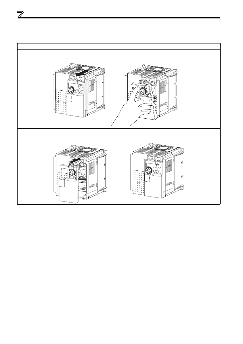
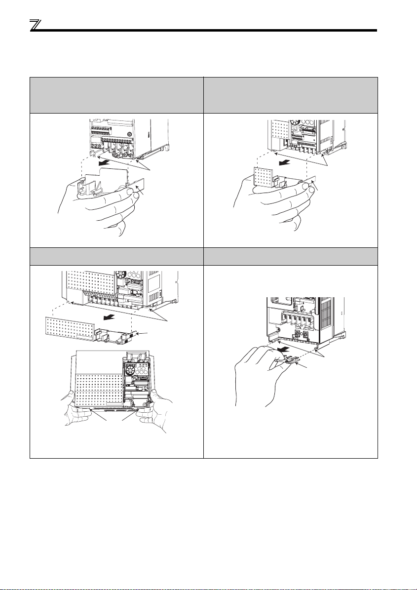
2.2 Removal and reinstallation of the cover
2.2.1 Front cover
FR-E720-3.7K or less, FR-E740-7.5K or less, FR-E720S, FR-E710W
zRemoval (Example of FR-E740-3.7K)
Remove the front cover by pulling it toward you in the direction of arrow.
zReinstallation (Example of FR-E740-3.7K)
To reinstall, match the cover to the inverter front and install it straight.
4
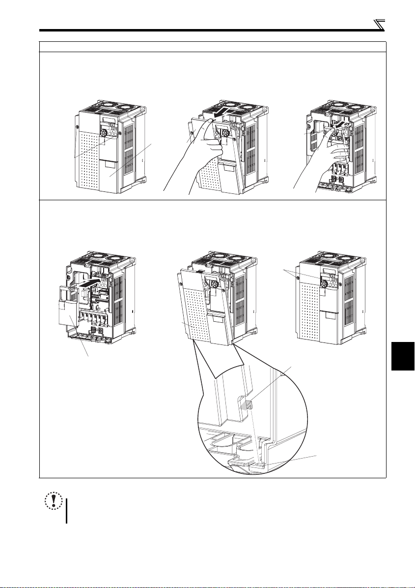
Removal and reinstallation of the cover
r
FR-E720-5.5K to 15K, FR-E740-11K, 15K
zRemoval (Example of FR-E740-11K)
1) Loosen the installation screws of the front cover 1.
2) Remove the front cover 1 by pulling it toward you in the direction of arrow.
3) Remove the front cover 2 by pulling it toward you in the direction of arrow.
1) 2) 3)
Front cover 2
Installation
screws
Front cover 1
zReinstallation (Example of FR-E740-11K)
1) Match the front cover 2 to the inverter front and install it straight.
2) Insert the two fixed hooks on the lower side of the front cover 1 into the sockets of the inverter.
3)Tighten the screw of the front cover 1.
1) 2) 3)
Front cover 1
Front cover 2
Tighten
the installation
screws
Fixed hook
2
Socket of the inverte
NOTE
Fully ma ke sure that the front c over has been rein stalled securely.
The sam e serial number is printed on the c apacity plate of the fro nt cover and the r ating plate of the inverter. Since
these plates have the s ame serial numbers, a lways reinstall the remo ved cover onto the orig inal inverter.
INSTALLATION AND WIRING
5
Removal and reinstallation of the cover
r
r
e
2.2.2 Wiring cover
zRemoval and reinstallation
The cover can be removed easily by pulling it toward you. To reinstall, fit the cover to the inverter along the guides.
FR-E720-0.1K to 0.75K
FR-E720S-0.1K to 0.4K
FR-E710W-0.1K to 0.4K
FR-E720-1.5K to 3.7K
FR-E740-0.4K to 3.7K
FR-E720S-0.75K to 2.2K
FR-E710W-0.75K
Guide
Wiring cove
Example of FR-E720S-0.4K Example of FR-E740-3.7K
FR-E740-5.5K, 7.5K
Guid
Wiring cover
Dent
For removal, push the d ent on the wiring cover with your finger and
pull toward you.
Example of FR-E740-5.5K Example of FR-E740-11K
Guide
Wiring cove
FR-E720-5.5K to 15K
FR-E740-11K, 15K
Guide
Wiring cover
6
Installation of the inverter and instructions
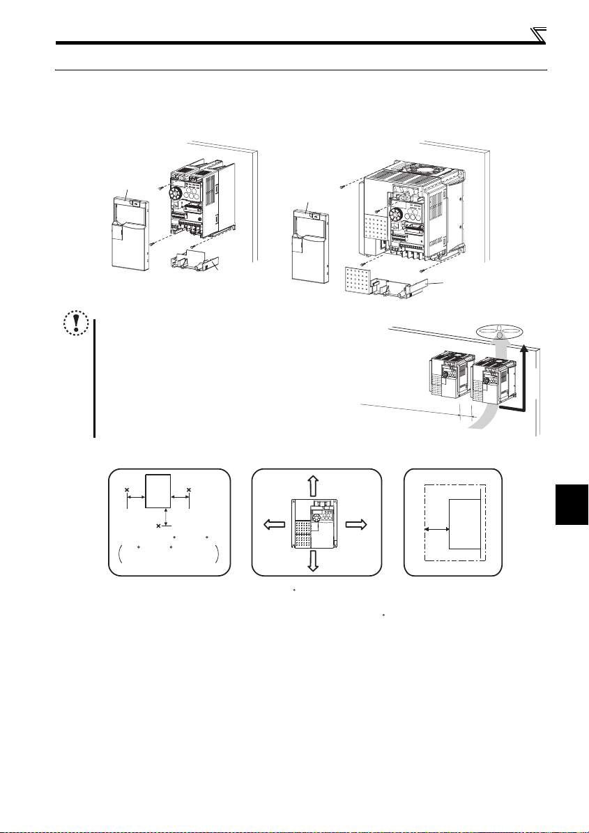
2.3 Installation of the inverter and instructions
Installation of the inverter
Enclosure surface mounting
Remove the front cover and wiring cover to fix the inverter to the surface.
FR-E720-0.1K to 0.75K
FR-E720S-0.1K to 0.4K
FR-E710W-0.1K t o 0.4K
Front cover
FR-E720-1.5K or more
FR-E740-0.4K or more
FR-E720S-0.75K or more
FR-E710W-0.75K
Front cover
Wiring cover
Note
When encasin g multiple inverters, ins tall them in parallel as a
cooling measure.
Install the inv erter vertically.
Install the inverter under the following conditions.
Surrounding air temperature and humidity
5cm
Measurement
position
Temperature: -10 C to +50 C
-10 C to +40 C for totally
-enclosed structure feature
Humidity: 90% RH or less
Leave enough clearances and
take cooling measures.
Inverter
Measurement
position
5cm
5cm
* When using the inverters at the surrounding air
temperature of 40 C or less, the inverters can be
installed without any clearance between them (0cm
clearance).
When surrounding air temperature exceeds 40 C,
clearances between the inverters should be 1cm or
more (5cm or more for the 5.5K or more).
1cm
or more*
Clearances (front)
10cm or more
10cm or more
R
efer to the clearances
1cm
or more*
Wiring cover
belo
w
.
Clearances (side)
Inverter
1cm
or more
*
* 5cm or more for the 5.5K
or more
Vertical
2
INSTALLATION AND WIRING
7

Installation of the inverter and instructions
The inverter consists of precision mechanical and electronic parts. Never install or handle it in any of the following
conditions as doing so could cause an operation fault or failure.
Vibration
Direct sunlight
(5.9m/s2 or less at
10 to 55Hz (directions of
X, Y, Z axes)
High temperature,
high humidity
Horizontal placement
When mounted inside
enclosure
Transportation by
holding front cover
or setting dial
Oil mist, flammable
gas, corrosive gas,
fluff, dust, etc.
Mounting to
combustible material
8
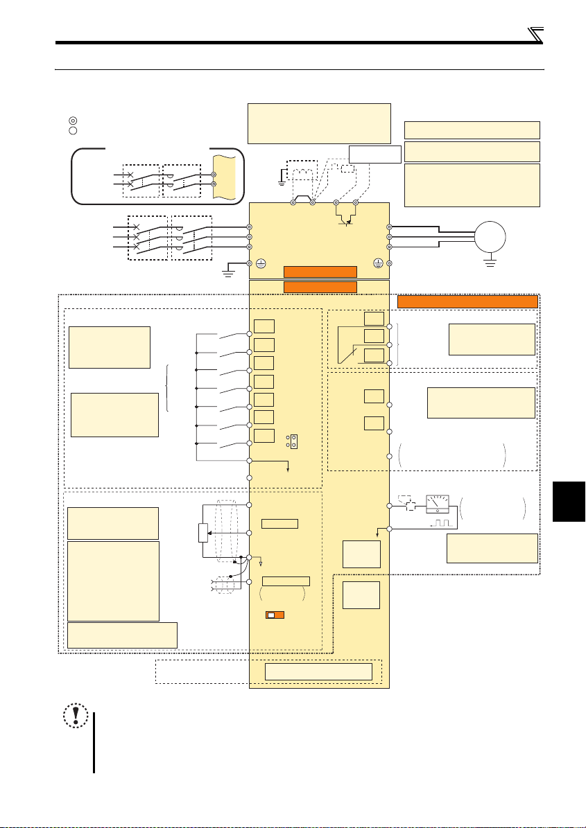
2.4 Wiring
2.4.1 Terminal connection diagram
Sink logic
Main circuit terminal
Control circuit terminal
Single-phase power input
Single-phase
AC power
supply
Three-phase
AC power
supply
MCCB MC
MCCB MC
R/L1
S/L2
*1. DC reactor (FR-HEL)
When connecting a DC reactor, remove the
jumper across P1 and P/+
Not available for single-phase 100V power
input model.
Jumper
*1
P1 P/+
*6
*8
PR
*7
Earth
(Ground)
R/L1
S/L2
T/L3
R
N/-
Brake unit
(Option)
*6 Terminal P1 is not available for single-
phase 100V power input model.
*7 A brake transistor is not built-in to the 0.1K
and 0.2K.
*8 Brake resistor (FR-ABR, MRS, MYS type)
Install a thermal relay to prevent an
overheat and burnout of the brake resistor.
(The brake resistor can not be connected
to the 0.1K and 0.2K.)
U
V
W
Wiring
Motor
IM
Earth
(Ground)
Main circuit
Control circuit
Standard control terminal block
Control input signals (No voltage input allowed)
Terminal functions vary
with the input terminal
assignment (Pr. 178 to
Pr. 184)
Multi-speed selection
*2 When using terminals PC-
SD as a 24VDC power
supply, take care not to
short across terminals
PC-SD.
Forward
rotation start
Reverse
rotation start
High
speed
Middle
speed
Low
speed
Output
stop
Reset
Contact input common
24VDC power supply
(Common for external power supply transistor)
Frequency setting signals (Analog)
*3 Terminal input specifications
can be changed by analog
input specifications
switchover (Pr. 73).
*4 Terminal input
specifications can be
changed by analog input
specifications switchover
(Pr. 267). Set the
voltage/current input
switch in the "V" position
to select voltage input (0
to 5V/0 to10V) and "I"
(initial value) to select
current input (4 to 20mA).
*5 It is recommended to use 2W1kΩ
when the frequency setting signal
is changed frequently.
3
Frequency
setting
potentiometer
1/2W1kΩ
Connector for
plug-in option connection
*5
Terminal 4
input
(Current
input)
2
1
(+)
(-)
STF
STR
RH
RM
RL
MRS
RES
SD
SOURCE
*2
PC
10(+5V)
2 0 to 5VDC
(0 to 10VDC)
*3
5(Analog common)
4 4 to 20mADC
0 to 5VDC
0 to 10VDC
IV
Voltage/current
input switch
*4
Option connector
SINK
*4
RUN
PU
connector
USB
connector
C
B
Relay output
(Fault output)
A
Running
FU
Frequency detection
Open collector output common
SE
Calibration resistor
FM
*9
SD
Relay output
Terminal functions vary
by Pr. 192 A,B,C terminal
function selection
Open collector output
Terminal functions vary with
the output terminal assignment
(Pr. 190 and Pr. 191)
Sink/source common
Indicator
(Frequency meter, etc.)
+
-
Moving-coil type
1mA full-scale
*9 It is not necessary when
calibrating the indicator
from the operation panel.
NOTE
To prevent a malfunction caused by noise, separate the signal cables more than 10cm from the power cabl es. Also
separate the main circuit w ire of the input side an d the output side.
After wiring, wir e offcuts must not be left in the in verter.
Wire offcuts can cause an alarm, failure or malfunction. Always keep the inverter clean. When drilling mounting holes
in an enclosure etc., take ca re not to allow chips and ot her foreign matter to enter the inverter.
The output of the single-phase power input specification is three-phase 200V.
Earth (Ground)
2
INSTALLATION AND WIRING
9

Wiring
2.4.2 Specification of main circuit terminal
Ter min al
Symbol
R/L1,
S/L2,
T/L3 ∗1
U, V, W I nverter output Connect a three-phase s quirrel-cage motor.
P/+, PR Br ake resistor connecti on
P/+, N/- B rake unit connection
P/+, P1 ∗2 DC reac tor connection
∗1 When using single-phase power input, terminals are R/L1 and S/L2.
∗2 Terminal P1 is not available for single-phase 100V power input model.
Terminal Name Description
AC power input
Earth (Ground) For earthing (groundin g) the inverter chassis. Must be earthed (ground ed).
Connect to the commercia l power supply.
Keep these terminals op en when using the high p ower factor converter (F R-HC) or
power regeneration common converter (FR-CV).
Connect a brake resistor (FR-ABR, MRS type, M YS type) across ter minals P/+ and
PR.
(The brake resistor can no t be connected to the 0.1K or 0.2K.)
Connect the brake unit (FR-B U2), power regeneratio n common converter (FR-C V)
or high power factor conver ter (FR-HC).
Remove the jumper across terminals P/+ and P1 and connect a DC reactor.
Single-phase 100V power input model is not com patible with DC reactor.
10
Wiring
r
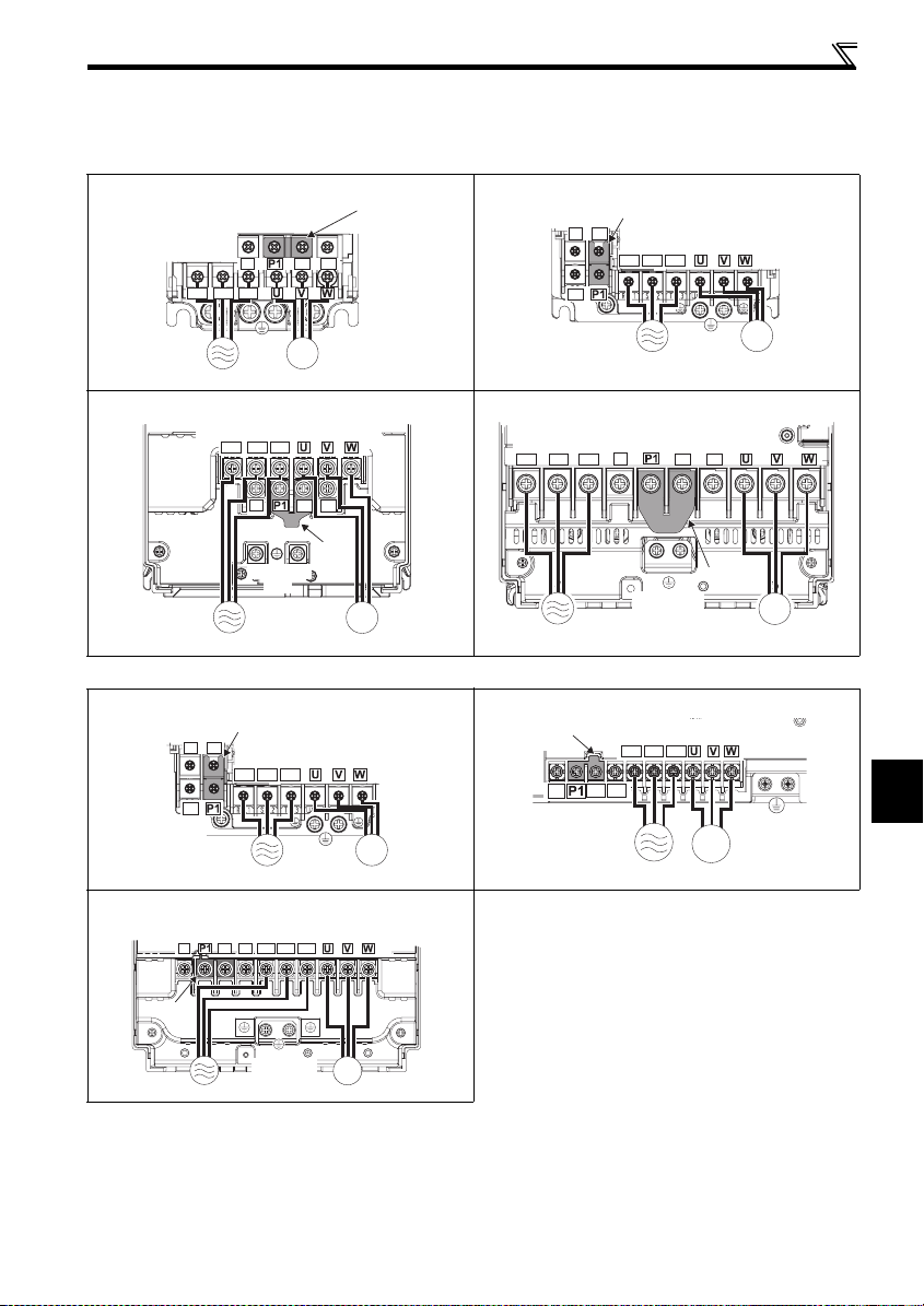
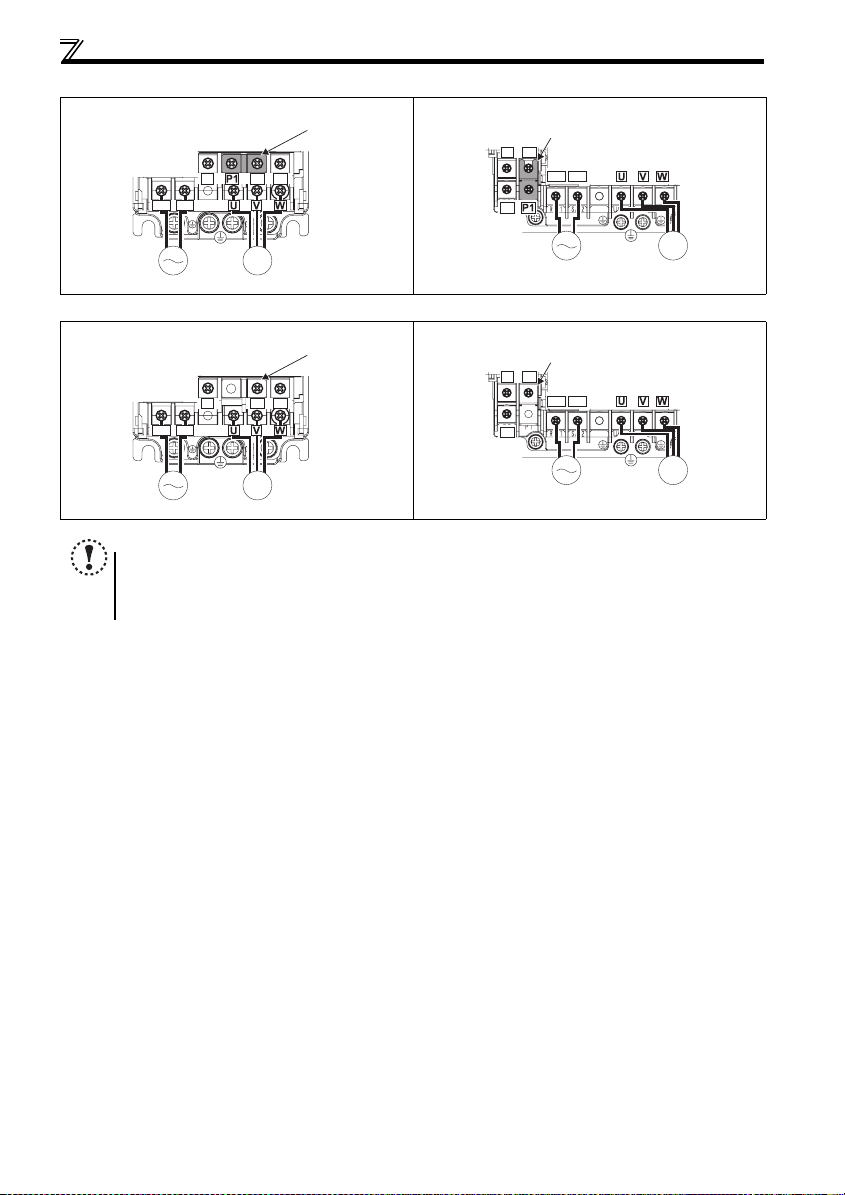
2.4.3 Terminal arrangement of the main circuit terminal, power supply and the motor wiring
Three-phase 200V class
FR-E720-0.1K to 0.75K FR-E720-1.5K to 3.7K
Screw size (M3.5)
N/-
R/L1 S/L2 T/L3
Jumpe
P/+ PR
N/-
PR
P/+
Jumper
Screw size (M4)
R/L1 S/L2 T/L3
Screw size
IM
(M3.5)
MotorPower supply
FR-E720-5.5K, 7.5K FR-E720-11K, 15K
Screw size (M5)
R/L1 S/L2 T/L3
N/-
Screw size
(M5)
P/+
PR
Jumper
Screw size(11K:M5/15K:M6)
R/L1 S/L2 T/L3
IM
Power supply
Three-phase 400V class
FR-E740-0.4K to 3.7K FR-E740-5.5K, 7.5K
Jumper
N/-
P/+
Screw size (M4)
R/L1 S/L2 T/L3
PR
FR-E740-11K, 15K
Screw size (11K: M4/15K: M5)
N/-
P/+
R/L1 S/L2 T/L3
PR
Screw size
(M4)
Motor
Jumper
N/-
IM
MotorPower supply
Power supply
N/-
P/+
PR
Screw size
(M5)
Screw size (M4)
R/L1 S/L2 T/L3
Screw size
(M4)
P/+
PR
Jumper
IM
MotorPower supply
IM
Motor
IM
MotorPower supply
Screw size
(M4)
2
Jumper
Power supply
Screw size
(11K: M4/15K: M5)
IM
Motor
INSTALLATION AND WIRING
11
Wiring
r
r
Single-phase 200V class
FR-E720S-0.1K to 0.4K FR-E720S-0.75K to 2.2K
Screw size (M3.5)
N/-
R/L1 S/L2
Jumpe
N/-
P/+ PR
PR
P/+
Jumper
Screw size (M4)
R/L1 S/L2
Screw size
(M3.5)
IM
MotorPower supply
Single-phase 100V class
FR-E710W-0.1K to 0.4K FR-E710W-0.75K
Screw size (M3.5)
N/-
R/L1 S/L2
Screw size
(M3.5)
IM
MotorPower supply
Jumpe
P/+ PR
NOTE
Make sure the power cables are connected to the R/L1, S/L2, T/L3. (Phase need not be matched.) Never connect the
power cable to the U, V, W of the inverter. Doing so w ill damage the inverter.
Connect t he motor to U, V, W. Turning ON the forward rotation switch (signal) at this time rotates the motor
counterclockwise when viewed from the load shaft.
N/-
PR
Power supply
Jumper
P/+
R/L1 S/L2
Power supply
Screw size
(M4)
Screw size (M4)
Screw size
(M4)
IM
Motor
IM
Motor
12
Wiring
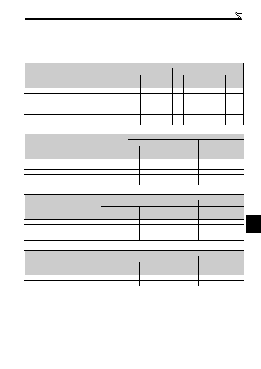
(1) Cable sizes etc., of the main control circuit terminals and earth (ground) terminals
Select the recommended cable size to ensure that a voltage drop will be 2% max.
If the wiring distance is long between the inverter and motor, a main circuit cable voltage drop will cause the motor torque to
decrease especially at the output of a low frequency.
The following table indicates a selection example for the wiring length of 20m.
Three-phase 200V class (when input power supply is 220V)
Earth
cable
Earth
cable
Earth
cable
Earth
cable
Cable Size
AWG ∗2
R/L1
S/L2
U, V, W
T/L3
Cable Size
AWG ∗2
R/L1
S/L2
U, V, W
T/L3
Cable Size
AWG ∗2
R/L1
U, V, W
S/L2
Cable Size
AWG ∗2
R/L1
U, V, W
S/L2
PVC Cables, etc. (mm2) ∗3
R/L1
S/L2
T/L3
U, V, W
Earth
(ground)
cable
PVC Cables, etc. (mm2) ∗3
R/L1
S/L2
T/L3
U, V, W
Earth
(ground)
cable
PVC Cables, etc. (mm2) ∗3
U, V, W
Earth
(ground)
cable
R/L1
S/L2
PVC Cables, etc. (mm2) ∗3
U, V, W
Earth
(ground)
cable
R/L1
S/L2
Crimping
N·m
Ter min al
R/L1
S/L2
T/L3
HIV Cables, etc. (mm2) ∗1
R/L1
U, V, W
S/L2
T/L3
U, V, W
(ground)
Ter mi nal
Applicable Inverter
Model
FR-E720-0.1K to 0.75K M3.5 1.2 2-3.5 2-3.5 2 2 2 1 4 14 2.5 2.5 2.5
FR-E720-1.5K, 2.2K M4 1.5 2-4 2-4 2 2 2 14 14 2.5 2.5 2.5
FR-E720-3.7K M4 1 .5 5. 5-4 5.5-4 3.5 3.5 3 .5 12 12 4 4 4
FR-E720-5.5K M5 2 .5 5. 5-5 5.5-5 5.5 5.5 5 .5 10 10 6 6 6
FR-E720-7.5K M5 2 .5 14-5 8-5 14 8 5.5 6 8 16 10 6
FR-E720-11K M5 2.5 14-5 14-5 14 14 14 6 6 16 16 16
FR-E720-15K M6(M5) 4.4 22-6 22-6 22 22 14 4 4 25 25 16
Screw
Size ∗4
Tightening
Torque
Three-phase 400V class (when input power supply is 440V)
Crimping
N·m
Ter min al
R/L1
S/L2
T/L3
HIV Cables, etc. (mm2) ∗1
R/L1
U, V, W
S/L2
T/L3
U, V, W
(ground)
Ter mi nal
Applicable Inverter
Model
FR-E740-0.4K to 3.7K M4 1.5 2-4 2-4 2 2 2 14 14 2.5 2 .5 2.5
FR-E740-5.5K M4 1. 5 5. 5-4 2 -4 3.5 2 3.5 12 1 4 4 2.5 4
FR-E740-7.5K M4 1 .5 5. 5-4 5.5-4 3.5 3.5 3.5 12 1 2 4 4 4
FR-E740-11K M4 1.5 5.5-4 5.5-4 5.5 5.5 8 10 10 6 6 10
FR-E740-15K M5 2.5 8-5 8-5 8 8 8 8 8 10 10 10
Screw
Size ∗4
Tightening
Torque
Single-phase 200V class (when input power supply is 220V)
Crimping
N·m
Ter min al
R/L1
S/L2
HIV Cables, etc. (mm2) ∗1
R/L1
U, V, W
S/L2
U, V, W
(ground)
Ter mi nal
Applicable Inverter
Model
FR-E720S-0.1K to 0.4K M3.5 1.2 2-3. 5 2-3.5 2 2 2 14 14 2.5 2.5 2.5
FR-E720S-0.75K M4 1.5 2-4 2-4 2 2 2 14 14 2.5 2.5 2.5
FR-E720S-1.5K M4 1.5 2-4 2-4 2 2 2 14 14 2.5 2.5 2.5
FR-E720S-2.2K M4 1.5 5.5-4 2-4 3.5 2 2 12 14 4 2.5 2.5
Screw
Size ∗4
Tightening
Torque
Single-phase 100V class (when input power supply is 100V)
Crimping
N·m
Ter min al
R/L1
S/L2
HIV Cables, etc. (mm2) ∗1
R/L1
U, V, W
S/L2
U, V, W
(ground)
Ter mi nal
Applicable Inverter
Model
FR-E710W-0.1K to 0.4K M3.5 1.2 2-3.5 2-3.5 2 2 2 14 14 2.5 2.5 2.5
FR-E710W-0.75K M4 1 .5 2-4 2-4 2 2 2 14 14 2.5 2.5 2.5
Screw
Size ∗4
Tightening
Torque
2
∗1
The cable size is that of the cable (HIV cable (600V class 2 vinyl-insulated cable) etc.) with continuous maximum permissible temperature of 75 °C. Assum es
that the surrounding air temperature is 50°C or less and the wiring distance is 20m or less.
∗2
The recommended cable size is that of the cable (THHW cable) with continuous maximum permissible temperature of 75°C. Assumes that the surrounding air
temperature is 40°C or less and the wi ring distance is 20m or less. (Selection example for use mainly in the United States.)
∗3
The recommended cable size is that of the cable (THHW cable) with continuous maximum permissible temperature of 70°C. Assumes that the surrounding air
temperature is 40°C or less and the wi ring distance is 20m or less. (Selection example for use mainly in Europe.)
∗4
The terminal screw size indicates the terminal size for R/L1, S/L2, T/L3, U, V, W, and a screw for earthing (grounding).
A screw for earthing (grounding) of t he FR-E720-15K is indicated in ( ).
For single-phase power input, the terminal screw size indicates the size of terminal screw for R/L1, S/L2, U, V, W, PR, P/+, N/-, P1 and a screw for earthing
(grounding).
INSTALLATION AND WIRING
13

Wiring
NOTE
Tighten the terminal screw to the specified torque. A scre w that has been tighten too loosely can cause a short circuit
or malfunction. A screw that has been tighten too tightly can cause a short circuit or malfunction due to the unit
breakage.
Use crimping terminals with insulation sleeve to wire the power supply and motor.
The line voltage drop can be calculated by the following formula:
line voltage drop [V]=
Use a larger diameter cable when the wiring distance is long or when it is desired to decrease the voltage drop (torque
reduction) in the low speed range.
(2) Earthing (Grounding) precautions
Leakage currents flow in the inverter. To prevent an electric shock, the inverter and motor must be earthed (grounded). This
inverter must be earthed (grounded). Earthing (Grounding) must conform to the requirements of national and local safety
regulations and electrical codes. (NEC section 250, IEC 536 class 1 and other applicable standards)
Use an neutral-point earthed (grounded) power supply for 400V class inverter in compliance with EN standard.
Use the dedicated earth (ground) terminal to earth (ground) the inverter. (Do not use the screw in the casing, chassis, etc.)
Use the thickest possible earth (ground) cable. Use the cable whose size is equal to or greater than that indicated on page
13 , and minimize the cable length. The earthing (grounding) point should be as near as possible to the inverter.
POINT
To be compliant with the European Directive (Low Voltage Directive), earth (ground) the inverter according to the
instructions on page 135.
3 × wire resistance[mΩ/m] × wiring distance[m] × current[A]
1000
14
Wiring
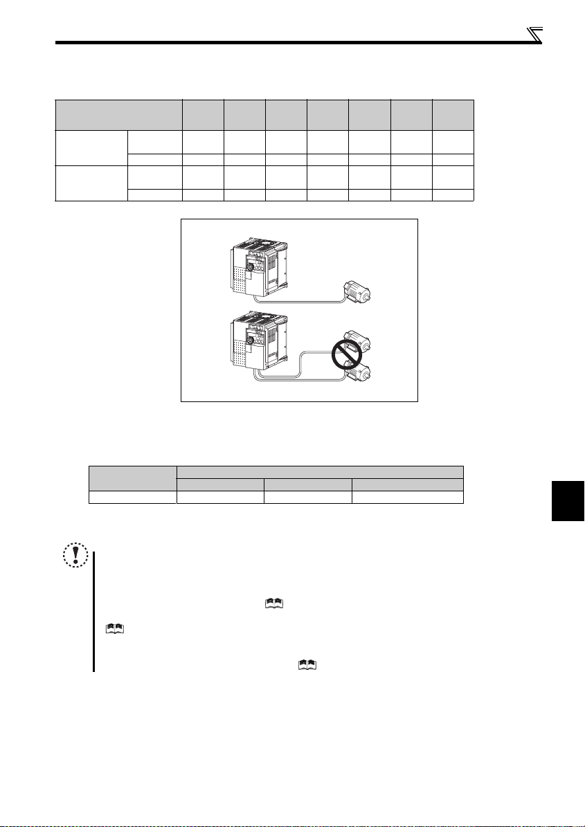
(3) Total wiring length
The overall wiring length for connection of a single motor or multiple motors should be within the value in the table
below.
Pr. 72 PWM frequency selection
Setting
(carrier frequency)
1 (1kHz) or less
2 to15
(2kHz to 14.5kHz)
100V class,
200V class
400V class - - 200m 200m 300m 500m 500m
100V class,
200V class
400V class - - 30m 100m 200m 300m 500m
0.1K 0.2K 0.4K 0.75K 1.5K 2.2K
200m 200m 30 0m 500m 50 0m 500m 500m
30m 100m 200m 300m 500m 500m 500m
Total wiring length (3.7K or more)
500m or less
300m
300m
300m+300m=600m
When driving a 400V class motor by the inverter, surge voltages attributable to the wiring constants may occur at the
motor terminals, deteriorating the insulation of the motor. Take the following measures 1) or 2) in this case.
1) Use a "400V class inverter-driven insulation-enhanced motor" and set frequency in Pr. 72 PWM frequency selection
according to wiring length
Carrier frequency 14.5kHz or le ss 8kHz or less 2kHz or less
50m or less 50m to 100m Exceeding 100m
Wiring Length
2) C onnect the s urge voltage s uppression filter (FR-ASF-H/FR-B MF-H) on the inverter output side.
3.7K
or More
2
NOTE
Especially for long-distance wiring, the inverter may be affected by a charging current caused by the stray
capacitances of the wiring, leading to a malfunction of the overcurrent protective function, fast response current limit
function, or stall prevention f unction or a malfunct ion or fault of the equi pment connected on t he inverter output side .
If malfunction of fast-response current limit function occurs, disable this function. If malfunction of stall prevention
function occurs, i ncrease the stall level. ( Pr. 22 Stall prevention operation level and Pr. 156 Stall prevention operation
selection in the chapter 4 of the Instruction Manual (applied))
Refer to the chapter 4 of the Instruction Manual (applied) for details of Pr. 72 PWM frequency selection. Refer to the m anual
of the option for details of surge voltage suppression filter (FR-ASF-H/FR-BMF-H).
When using the automatic restart after instantaneous power failure function with wiring length exceeding 100 m,
select without frequen cy search (Pr. 162 = "1, 11"). (
Refer to the chapter 4 of the Instruction Manua l (applied))
INSTALLATION AND WIRING
15
Wiring
2.4.4 Standard control circuit terminal
indicates that terminal functions can be selected using Pr. 178 to Pr. 184, Pr. 190 to Pr. 192 (I/O terminal function
selection). ( Refer to the Instruction Manual (applied)).
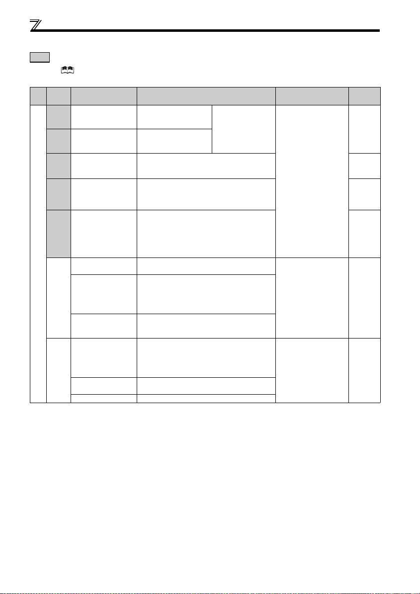
(1) Input signal
Ter min al
Typ e
Symbol
STF Forward rotation start
STR Reverse rotation start
RH,
RM,
RL
MRS Output stop
RES Reset
Contact input
SD
PC
Terminal Name Description Rated Specifications
Turn ON the STF signal to
start forward rotation and
turn it OFF to stop.
Turn ON the STR signal to
start reverse rotation and
turn it OFF to stop.
Multi-speed selection
Contact input common
(sink) (initial setting)
External transistor
common (source)
24VDC power supply
common
External transistor
common (sink)
(initial setting)
Contact input common
(source)
24VDC power supply Can be used as 24VDC 0.1A powe r supply.
Multi-speed can be selec ted according to the
combination of RH, RM and RL signals.
Turn ON the MRS signal (20ms or more) to stop the
inverter output.
Use to shut off the inverter ou tput when stopping the
motor by electromagne tic brake.
Used to reset fault output provided when fault occ urs.
Turn ON the RES signal for more tha n 0.1s, then turn it
OFF.
Factory setting is for res et always. By setting Pr. 75,
reset can be set to enabl ed only at fault occur rence.
Recover about 1s after res et is cancelled.
Common terminal for contact input terminal (sink logic)
and terminal FM.
When connecting the t ransistor output (open c ollector
output), such as a prog rammable controller, when
source logic is selecte d, connect the external p ower
supply common for trans istor output to this ter minal to
prevent a malfunction c aused by undesirable currents.
Common output terminal for 24VDC 0.1A power
supply (PC terminal).
Isolated from terminals 5 and SE.
When connecting the t ransistor output (open c ollector
output), such as a program mable controller, when sink
logic is selected, connec t the external power sup ply
common for transistor ou tput to this terminal to prevent
a malfunction caused by undesirable currents.
Common terminal for contact input terminal (source
logic).
When the STF and STR
signals are turned ON
simultaneously, the stop
command is given.
Input resistance 4.7kΩ
Voltage when contacts are
open
21 to 26VDC
When contacts are short-
circuited
4 to 6mADC
——
Power supply voltage range
22 to 26.5VDC
permissible load current
100mA
Refer to
Page
61
63
Instruction
Manual
(applied)
96
20
16
Wiring
Ter min al
Typ e
Symbol
10
2
Frequency setting
4
5
Terminal Name Description Rated Specifications
Used as power supply when conne cting potentiometer
Frequency setting power
supply
Frequency setting
(voltage)
Frequency setting
(current)
Frequency setting
common
for frequency setting (spe ed setting) from outside o f
the inverter.
( Refer to the chapter 4 of the Instruction Manual
(applied))
Inputting 0 to 5VDC (or 0 to 10V) provides the
maximum output freque ncy at 5V (10V) and ma kes
input and output proporti onal. Use Pr. 73 to switch
between input 0 to 5VDC input (init ial setting) and 0 to
10VDC.
Inputting 4 to 20mADC (or 0 to 5V, 0 to 10V) provides
the maximum output fre quency at 20mA and mak es
input and output proportion al. This input signal is val id
only when the AU signa l is ON (terminal 2 inp ut is
invalid). U se Pr. 267 to switch from among input 4 to
20mA (initial setting), 0 to 5VDC and 0 to 10VDC . Set
the voltage/current input sw itch in the "V" position to
select voltage input (0 to 5V /0 to 10V).
( Refer to the chapter 4 of the Instruction Manual
(applied)).
Frequency setting sign al (terminal 2, 4) commo n
terminal. Do not earth (gr ound).
5VDC
permissible load current
10mA
Input resistance10kΩ ± 1kΩ
Permissible maximum
voltage 20VDC
Current input:
Input resistance 233Ω ± 5Ω
Maximum permissible
current 30mA
Voltage input:
Input resistance10kΩ ± 1kΩ
Permissible maximum
voltage 20VDC
Current input
(initial status)
——
NOTE
Set Pr. 267 and a voltage/current input switch correctly, then input analog signals in accordance with the settings.
Applying a voltage with voltage/current input switch in "I" position (current input is selected) or a current with switch in
"V" position (voltage input is selected) could cause component damage of the inverter or analog circuit of output
devices.
Refer to
Page
59, 65
59, 65
60, 68
Voltage input
17
2
INSTALLATION AND WIRING

Wiring
(2) Output signal
Ter min al
Typ e
Relay
Terminal Name Description Rated Specifications
Symbol
Relay output (fault
A, B, C
output)
1 changeover contact out put indicates that the i nverter
protective function has activated and the output stopped.
Fault: discontinuity acros s B-C (continuity across A -C),
Normal: continuity across B-C (discontinuity acros s A-C)
Contact capacity:230VAC
0.3A
(power factor =0.4)
30VDC 0.3A
Reference
Page
Instruction
Manual
(applied)
RUN Inverter running
Open collector
FU Frequency dete ction
Open collector output
SE
common
FM For meter
Pulse
(3) Communication
Terminal
Typ e
Symbol
— PU connector
RS-485
— USB connector
USB
Switched low when the inverter output frequency is equal to
or higher than the starting frequency (initial value 0 .5Hz).
Switched high during stop or DC injection brake operatio n.*
Switched low when the inverter output frequency is equal to
or higher than the preset detecte d frequency and high when
less than the preset de tected frequency.*
Common terminal of termina l RUN and FU. — —
Select one e.g. output
frequency from monito r items.
Not output during inver ter
reset. Not output during
inverter reset.
The output signal is
proportional to the magnitude
of the corresponding
monitoring item.
Output item:
Output frequency (initi al
setting)
Permissible load 24VDC
(maximum 27VDC) 0.1A
(a voltage drop is 3.4V
maximum when the signal
is ON)
* Low indicates that the open
collector output transistor is
ON (conducts).
High indicates that the
transistor is OFF (does not
conduct).
Permissible load curr ent
1mA
1440 pulses/s at 60H z
Terminal Name Description
With the PU connecto r, communication can be made throu gh RS-485.
Conforming standard: EIA-48 5 (RS-485)
Transmission format: Multidrop lin k
Communication speed: 4800 to 38400bps
Overall length: 500m
The FR Configurator can be operated by connec ting the inverter to the
personal computer through USB.
Interface: conforms to USB1.1
Transmission speed: 12Mbps
Connector: USB mini B conn ector (receptacle mini B ty pe)
Instruction
Manual
(applied)
Instruction
Manual
(applied)
Instruction
Manual
(applied)
Reference
Page
23
25
18
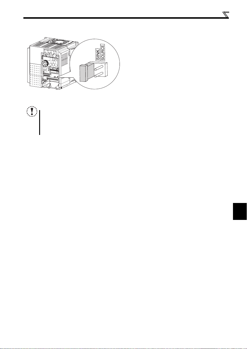
2.4.5 Changing the control logic
The input signals are set to sink logic (SINK) when shipped from
the factory.
To change the control logic, the jumper connector above the
control terminal must be moved to the other position.
To change to source logic, change the jumper connector in
the sink logic (SINK) position to source logic (SOURCE)
position using tweezers , a pair of long-nose pliers etc.
Change the jumper connector position before switching power
ON.
NOTE
Fully ma ke sure that the front c over has been rein stalled securely.
The capacity pla te is placed on the front co ver and the rating plate is on the inverter. Since these plat es have the
same serial numbers, always reinstall the remove d cover onto the original inverter.
The sink-source logic change-over jumper connector must be fitted in only one of those positions. If it is fitted in both
positions at the same time, the inverter may be damaged.
Wiring
19
2
INSTALLATION AND WIRING
Wiring
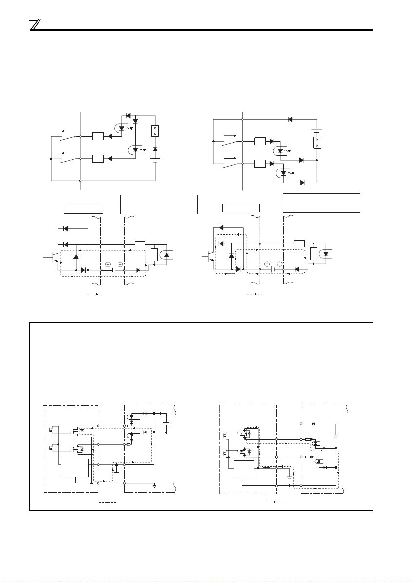
(1) Sink logic type and source logic type
In sink logic, a signal switches ON when a current flows from the corresponding signal input terminal.
Terminal SD is common to the contact input signals. Terminal SE is common to the open collector output signals.
In source logic, a signal switches ON when a current flows into the corresponding signal input terminal.
Terminal PC is common to the contact input signals. Terminal SE is common to the open collector output signals.
Current flow concerning t he input/output signa l when sink logic is
selected
Sink logic
Current
STF
STR
SD
R
R
Sink
connector
Current flow concerni ng the input/output sign al when source logic is
selected
Source logic
PC
Current
STF
R
STR
R
Source
connector
DC input (sink type)
24VDC
Current flow
<Example: QX40>
TB1
R
TB17
R
Inverter
RUN
SE
When using an external power supply for trans istor output
Sink logic type
Use terminal PC as a common terminal, and perform
wiring as shown below. (Do not connect terminal SD of the
inverter with terminal 0V of the external power supply.
When using terminals PC-SD as a 24VDC power supply,
do not install an external power supply in parallel with the
inverter. Doing so may cause a malfunction in the inverter
due to undesirable currents.)
STF
STR
PC
SD
Current flow
Inverter
24VDC
(SD)
QY40P type transistor
output unit
Constant
voltage
circuit
TB1
TB2
TB17
TB18
24VDC
DC input (source type)
Inverter
RUN
SE
24VDC
Current flow
<Example: QX80>
TB1
R
TB18
R
Source logic type
Use terminal SD as a common terminal, and perform
wiring as shown below. (Do not connect terminal PC of the
inverter with terminal +24V of the external power supply.
When using terminals PC-SD as a 24VDC power supply,
do not install an external power supply in parallel with the
inverter. Doing so may cause a malfunction in the inverter
due to undesirable currents.)
PC
STF
STR
24VDC
SD
Inverter
24VDC
(SD)
QY80 type transistor
output unit
Constant
voltage
Fuse
circuit
TB1
TB2
TB17
TB18
Current flow
20
2.4.6 Wiring of control circuit
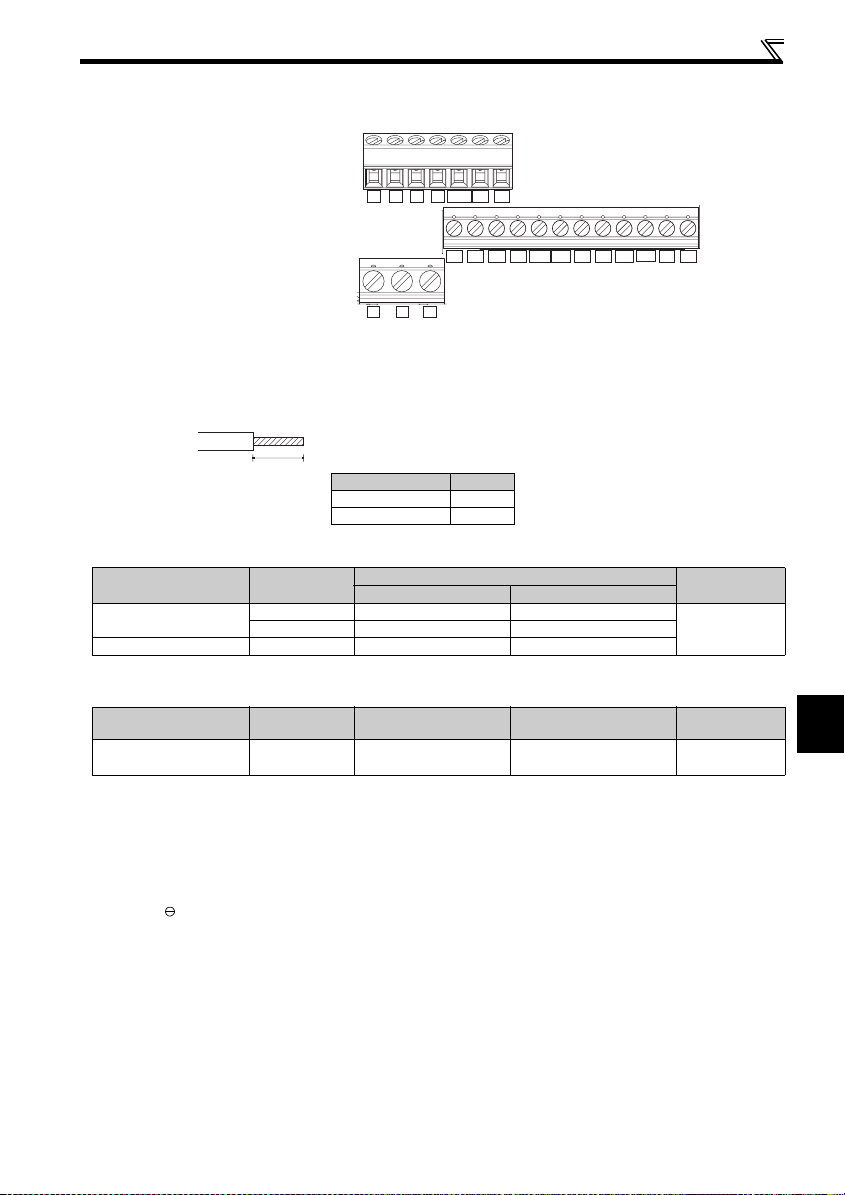
(1) Standard control circuit terminal layout
Terminal screw size
M3: (Terminal A, B, C)
M2: (Other than the above)
Wiring
10 2 5 4 RUN FU SE
FM
CBA
RHRMRL
STF STR
PCSD
RESMRS
SDSD
(2) Wiring method
1) Strip off the sheath of the wire of the control circuit to wire.
Strip off the sheath about the size below. If the length of the sheath peeled is too long, a short circuit may occur among
neighboring wires. If the length is too short, wires might come off.
Wire stripping size
Wire the stripped wire after twisting it to prevent it from
becoming loose. In addition, do not solder it.
L
Use a bar terminal as necessary.
L(mm)
Terminal A, B, C 6
Other than the above 5
Introduced products on bar terminals: (as of Mar., 2008)
zPhoenix Contact Co.,Ltd.
Terminal Screw Size
M3 (terminal A, B, C)
M2 (other than the above) 0.3, 0.5 AI 0,5-6WH A 0,5-6
Wire Size (mm2)
0.3, 0.5 AI 0,5-6WH A 0,5-6
0.75 AI 0,75-6GY A 0,75-6
With Insulation Sleeve Without Insulation Sleeve
Bar Terminal Model
Bar terminal
crimping tool
CRIMPFOX ZA3
zNICHIFU Co.,Ltd.
Terminal Screw Size
M3 (terminal A, B, C)
M2 (other than the above)
Wire Size (mm2)
0.3 to 0.75 BT 0.75-7 VC 0.75 NH 67
Bar terminal product
number
Insulation product number
Bar terminal
crimping tool
2) Loosen the terminal screw and insert the wire into the terminal.
3) Tighten the screw to the specified torque.
Undertightening can cause wire disconnection or malfunction. Overtightening can cause a short circuit or malfunction due
to damage to the screw or unit.
Tightening torque: 0.5N·m to 0.6N·m (terminal A, B, C)
0.22N·m to 0.25N·m (other than the above)
* Screwdriver: Small flathead screwdriver (Tip thickness: 0.4mm/tip width: 2.5mm)
2
21
INSTALLATION AND WIRING
 Loading...