

Mitsubishi Electric FR-D700, fr-e700, fr-e720-008, fr-e740-016, fr-e710w-008 Installation Manuallines
...
INVERTER
FR-D700
INSTALLATION GUIDELINE
FR-D740-012 to 160-EC
FR-D720S-008 to 100-EC
Thank you for choosing this Mitsubishi Inverter.
Please read through this Installation Guideline and a CD-ROM enclosed to operate this inverter correctly.
Do not use this product until you have a full knowledge of the equipment, safety information and
instructions.
Please forward this Installation Guideline and the CD-ROM to the end user.
CONTENTS
PRODUCT CHECKING AND PARTS IDENTIFICATION ..........1
1
OUTLINE DIMENSION DRAWINGS........................................3
2
WIRING..................................................................................4
3
PRECAUTIONS FOR USE OF THE INVERTER.....................10
4
FAILSAFE OF THE SYSTEM WHICH USES THE INVERTER 12
5
PARAMETER LIST ...............................................................13
6
TROUBLESHOOTING...........................................................18
7
700
This Installation Guideline provides handling information and precautions for use of the equipment.
G
Please forward this Installation Guideline to the end user.
This section is specifically about safety matters
Do not attempt to install, operate, maintain or inspect the
inverter until you have read through the Installation
Guideline and appended documents carefully and can use
the equipment correctly. Do not use this product until you
have a full knowledge of the equipment, safety information
and instructions.
In this Installation Guideline, the safety instruction levels
are classified into "WARNING" and "CAUTION".
WARNING
CAUTION
Note that even the level may lead to a serious
consequence according to conditions. Please follow the
instructions of both levels because they are important to
personnel safety.
1. Electric Shock Prevention
Assumes that incorrect handling may
cause hazardous conditions, resulting
in death or severe injury.
Assumes that incorrect handling may
cause hazardous conditions, resulting
in medium or slight injury, or may
cause physical damage only.
CAUTION
WARNIN
z While power is on or when the inverter is running, do not
open the front cover. Otherwise you may get an electric
shock.
z Do not run the inverter with the front cover or wiring cover
removed. Otherwise, you may access the exposed highvoltage terminals or the charging part of the circuitry and
get an electric shock.
z Even if power is off, do not remove the front cover except
for wiring or periodic inspection. You may access the
charged inverter circuits and get an electric shock.
z Before starting wiring or inspection, switch off power,
check to make sure that the operation panel indicator is
off, wait for at least 10 minutes after the power supply has
been switched off, and check that there are no residual
voltage using a tester or the like. The capacitor is charged
with high voltage for some time after power off and it is
dangerous.
z This inverter must be earthed (grounded). Earthing
(grounding) must conform to the requirements of national
and local safety regulations and electrical code. (NEC
section 250, IEC 536 class 1 and other applicable
standards)
z Any person who is involved in the wiring or inspection of
this equipment should be fully competent to do the work.
z Always install the inverter before wiring. Otherwise, you
may get an electric shock or be injured.
z Perform setting dial and key operations with dry hands to
prevent an electric shock. Otherwise you may get an
electric shock.
z Do not subject the cables to scratches, excessive stress,
heavy loads or pinching. Otherwise, you may get an
electric shock.
z Do not change the cooling fan while power is on. It is
dangerous to change the cooling fan while power is on.
z Do not touch the printed circuit board with wet hands.
Otherwise, you may get an electric shock.
z When measuring the main circuit capacitor capacity, the
DC voltage is applied to the motor for 1s at powering off.
Never touch the motor terminal, etc. right after powering
off to prevent an electric shock.
2. Fire Prevention
CAUTION
z Install the inverter on a nonflammable wall without holes
(so that nobody can touch the inverter heatsink on the
rear side, etc.). Mounting it to or near combustible
material can cause a fire.
z If the inverter has become faulty, switch off the inverter
power. A continuous flow of large current could cause a
fire.
z When using a brake resistor, make up a sequence that will
turn off power when an alarm signal is output. Otherwise,
the brake resistor may excessively overheat due to
damage of the brake transistor and such, causing a fire.
z Do not connect a resistor directly to the DC terminals +
and -. This could cause a fire.
3.Injury Prevention
CAUTION
z
Apply only the voltage specified in the instruction manual
to each terminal. Otherwise, burst, damage, etc. may occur.
z Ensure that the cables are connected to the correct
terminals. Otherwise, burst, damage, etc. may occur.
z Always make sure that polarity is correct to prevent
damage, etc. Otherwise, burst, damage, etc. may occur.
z While power is on or for some time after power-off, do not
touch the inverter as they will be extremely hot. Doing so
can cause burns.
4. Additional Instructions
Also note the following points to prevent an accidental failure,
injury, electric shock, etc.
(1) Transportation and mounting
CAUTION
z Transport the product using the correct method that
corresponds to the weight. Failure to observe this could
lead to injuries.
z Do not stack the inverter boxes higher than the number
recommended.
z Ensure that installation position and material can
withstand the weight of the inverter. Install according to
the information in the instruction manual.
z Do not install or operate the inverter if it is damaged or
has parts missing.
z When carrying the inverter, do not hold it by the front
cover or setting dial; it may fall off or fail.
z Do not stand or rest heavy objects on the product.
z Check the inverter mounting orientation is correct.
z Prevent other conductive bodies such as screws and
metal fragments or other flammable substance such as oil
from entering the inverter.
z As the inverter is a precision instrument, do not drop or
subject it to impact.
z Use the inverter under the following environmental
conditions: Otherwise, the inverter may be damaged.
Surrounding
air
temperature
Ambient
humidity
Storage
temperature
Atmosphere
Environment
Altitude/
vibration
∗1 Temperature applicable for a short time, e.g. in transit.
-10°C to +50°C (non-freezing)
90%RH maximum (non-condensing)
-20°C to +65°C *1
Indoors (free from corrosive gas, flammable gas,
oil mist, dust and dirt)
Maximum 1000m above sea level for standard
operation. After that derate by 3% for every extra
500m up to 2500m (91%) .
2
or less
5.9m/s
A-1
(2) Wiring
G
CAUTION
z Do not install a power factor correction capacitor or surge
suppressor/capacitor type filter on the inverter output
side. These devices on the inverter output side may be
overheated or burn out.
z The connection orientation of the output cables U, V, W to
the motor will affect the direction of rotation of the motor.
(3) Trial run
CAUTION
z Before starting operation, confirm and adjust the
parameters. A failure to do so may cause some machines
to make unexpected motions.
(4) Usage
WARNIN
z When you have chosen the retry function, stay away from
the equipment as it will restart suddenly after trip.
z Since pressing key may not stop output depending
on the function setting status, provide a circuit and switch
separately to make an emergency stop (power off,
mechanical brake operation for emergency stop, etc).
z Make sure that the start signal is off before resetting the
inverter alarm. A failure to do so may restart the motor
suddenly.
z The load used should be a three-phase induction motor
only.
Connection of any other electrical equipment to the
inverter output may damage the equipment.
z Do not modify the equipment.
z Do not perform parts removal which is not instructed in
this manual. Doing so may lead to fault or damage of the
product.
(5) Emergency stop
CAUTION
z Provide a safety backup such as an emergency brake
which will prevent the machine and equipment from
hazardous conditions if the inverter fails.
z When the breaker on the inverter input side trips, check
for the wiring fault (short circuit), damage to internal parts
of the inverter, etc. Identify the cause of the trip, then
remove the cause and power on the breaker.
z When any protective function is activated, take the
appropriate corrective action, then reset the inverter, and
resume operation.
(6) Maintenance, inspection and parts replacement
CAUTION
z Do not carry out a megger (insulation resistance) test on
the control circuit of the inverter. It will cause a failure.
(7) Disposal
CAUTION
z Treat as industrial waste.
General instruction
Many of the diagrams and drawings in this Installation
Guideline show the inverter without a cover, or partially
open. Never operate the inverter in this manner. Always
replace the cover and follow this Installation Guideline
when operating the inverter.
CAUTION
z
The electronic thermal relay function does not guarantee
protection of the motor from overheating. It is recommended
to install both an external thermal and PTC thermistor for
overheat protection.
z Do not use a magnetic contactor on the inverter input for
frequent starting/stopping of the inverter. Otherwise, the
life of the inverter decreases.
z Use a noise filter to reduce the effect of electromagnetic
interference. Otherwise nearby electronic equipment may
be affected.
z Take measures to suppress harmonics. Otherwise power
supply harmonics from the inverter may heat/damage the
power factor correction capacitor and generator.
z When a 400V class motor is inverter-driven, please use an
insulation-enhanced motor or measures taken to
suppress surge voltages. Surge voltages attributable to
the wiring constants may occur at the motor terminals,
deteriorating the insulation of the motor.
z When parameter clear or all parameter clear is performed,
reset the required parameters before starting operations.
Each parameter returns to the initial value.
z The inverter can be easily set for high-speed operation.
Before changing its setting, fully examine the
performances of the motor and machine.
z In addition to the inverter’s holding function, install a
holding device to ensure safety.
z Before running an inverter which had been stored for a
long period, always perform inspection and test
operation.
z For prevention of damage due to static electricity, touch
nearby metal before touching this product to eliminate
static electricity from your body.
A-2
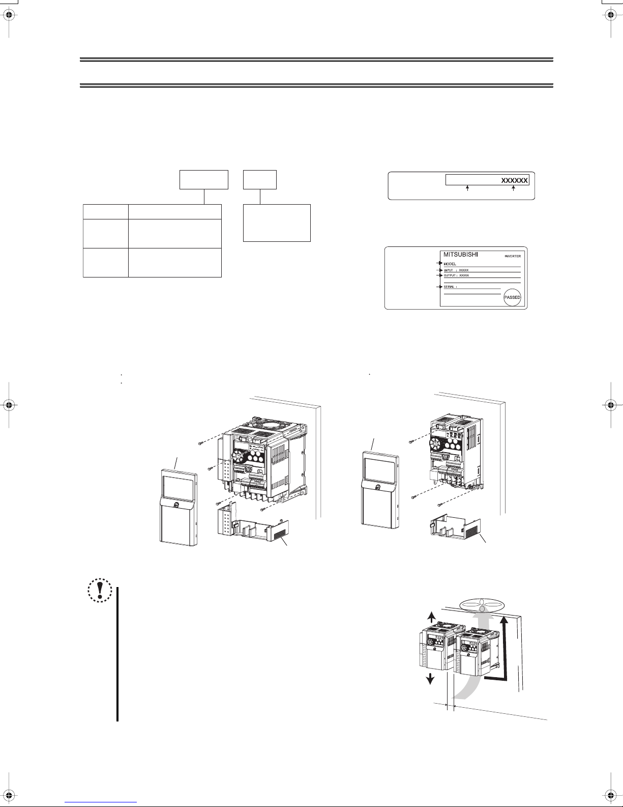
1 PRODUCT CHECKING AND PARTS IDENTIFICATION
Unpack the inverter and check the capacity plate on the front cover and the rating plate on the inverter side face to ensure that
the product agrees with your order and the inverter is intact.
Inverter type Capacity plate
---
FR D740 036
Symbol Voltage class
D740
D720S
z Installation of the inverter
Three-phase 400V
class
Single-phase 200V
class
Displays the
rated current
EC
Enclosure surface mounting
Remove the front cover and wiring cover to fix the inverter to the surface.
FR-D740-012 to 160
FR-D720S-070 and 100
Front cover
Capacity plate
Rating plate
Rating plate
Inverter type
Output rating
Serial number
FR-D720S-008 to 042
Front cover
Input rating
FR-D740-036-EC
Inverter type
FR-D740-036-EC
Serial number
Note
y When encasing multiple inverters, install them in parallel as a
cooling measure.
y When using the inverters at the surrounding air temperature of
40
°
C or less, the inverters can be installed without any clearance
between them (0cm clearance). When surrounding air
temperature exceeds 40
should be 1cm or more (5cm or more for the FR-D740-120 or
more).
y Install the inverter vertically.
Wiring cover
°
C, clearances between the inverters
Wiring cover
10cm or more
Vertical
10cm or more
Refer to the clearances
on the left.
1
PRODUCT CHECKING AND PARTS IDENTIFICATION
z General Precaution
The bus capacitor discharge time is 10 minutes. Before starting wiring or inspection, switch power off, wait for more than 10
minutes, and check for residual voltage between terminal + and - with a meter etc., to avoid a hazard of electrical shock.
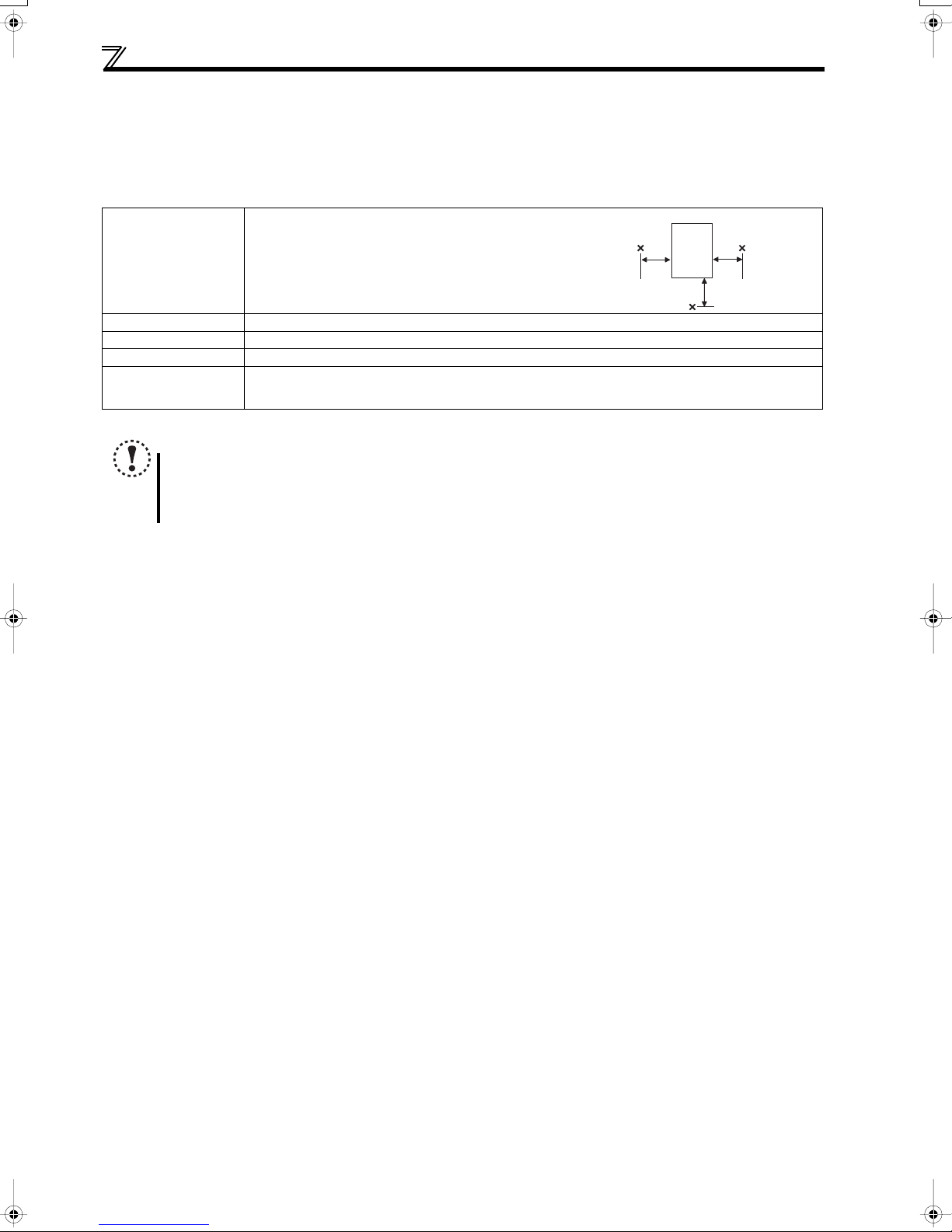
z Environment
Before installation, check that the environment meets following specifications.
Surrounding Air
Temperature
Ambient humidity
Storage temperature
Ambience
Altitude, vibration
Note
y Install the inverter on a strong surface securely and vertically with bolts.
y Leave enough clearances and take cooling measures.
y Avoid places where the inverter is subjected to direct sunlight, high temperature and high humidity.
y Install the inverter on a non-combustible wall surface.
-10°C to +50°C (non-freezing)
5cm 5cm
Measurement
position
90% RH maximum
-20°C to +65°C (Temperature applicable for a short time, e.g. in transit.)
Indoors (free from corrosive gas, flammable gas, oil mist, dust and dirt)
Maximum 1000m above sea level for standard operation. After that derate by 3% for every extra 500m
up to 2500m (91%).
5.9m/s2 or less
Measurement
position
Inverter
5cm
2
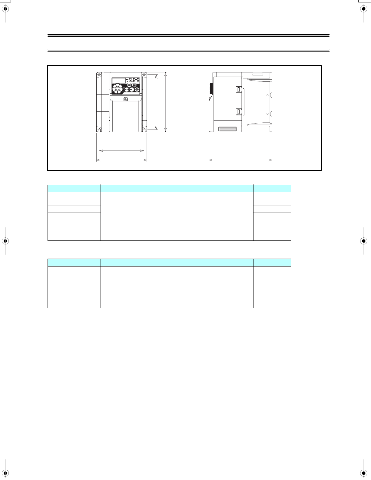
2 OUTLINE DIMENSION DRAWINGS
H
H1
W1
W
• Three-phase 400V class
Inverter Type W W1 H H1 D
FR-D740-012
FR-D740-022
FR-D740-036
FR-D740-050 155.5
FR-D740-080 165.5
FR-D740-120
FR-D740-160
108 96 128 118
220 208 150 138 155
D
(Unit:mm)
129.5
135.5
• Single-phase 200V class
Inverter Type W W1 H H1 D
FR-D720S-008
FR-D720S-014
FR-D720S-025
FR-D720S-042 162.5
FR-D720S-070 108 96 155.5
FR-D720S-100 140 128 150 138 145
68 56
128 118
80.5
142.5
3
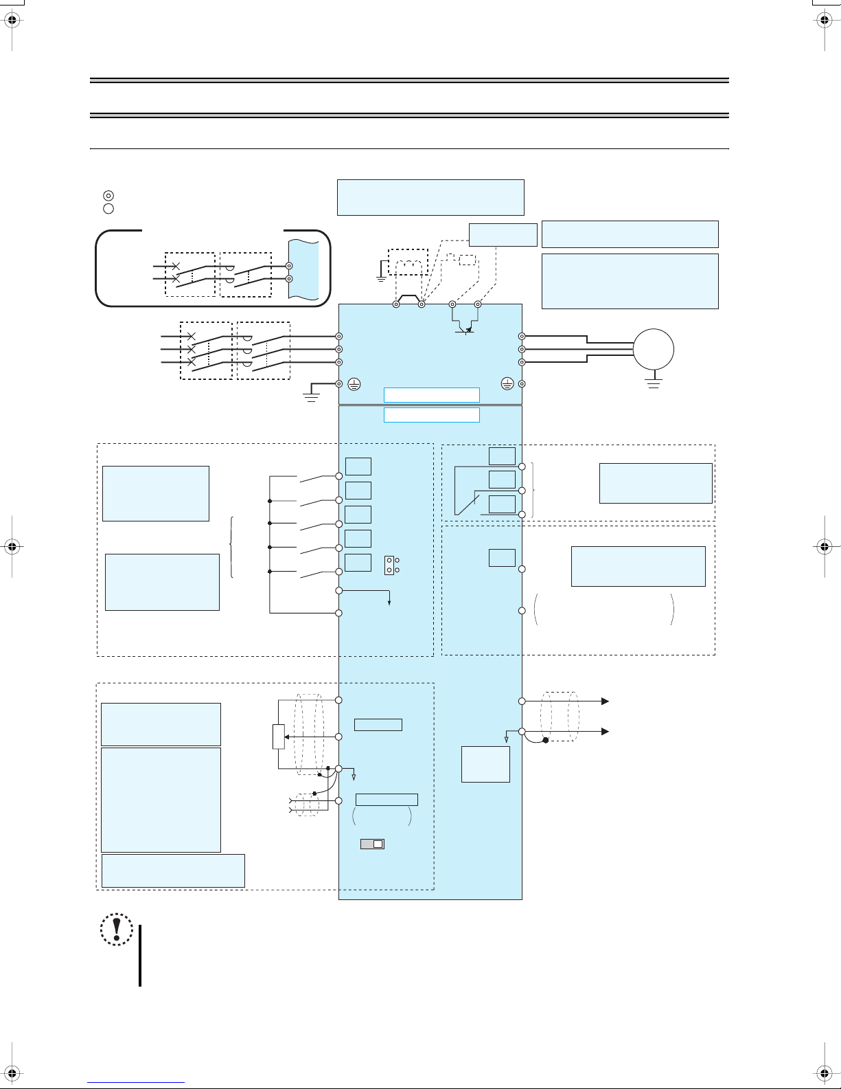
Terminal connection diagram
3WIRING
3.1 Terminal connection diagram
Source logic
Main circuit terminal
Control circuit terminal
Single-phase power input
MCCB MC
Single-phase
AC power
supply
MCCB MC
Three-phase
AC power
supply
Earth
(Ground)
Control input signals (No voltage input allowed)
Terminal functions vary
with the input terminal
assignment (Pr. 178 to
Pr. 182)
Multi-speed selection
*2 When using terminals PC-
SD as a 24VDC power
supply, take care not to
short across terminals
PC-SD.
Contact input common
(Common for external power supply transistor)
Contact input common
Forward
rotation start
Reverse
rotation start
High
speed
Middle
speed
Low
speed
24VDC power supply
*
1. DC reactor (FR-HEL)
When connecting a DC reactor, remove the
jumper across P1-
L1
N
Earth
(Ground)
R/L1
S/L2
T/L3
Jumper
P1
+
*1
PR
+
Main circuit
Brake unit
(Option)
R
*7
-
*6
*6 A brake transistor is not built-in to the
FR-D720S-008 and 014.
*7 Brake resistor (FR-ABR, MRS)
Install a thermal relay to prevent an
overheat and burnout of the brake resistor.
(The brake resistor can not be connected
to the FR-D720S-008 and 014.)
U
V
W
Motor
IM
Earth (Ground)
Control circuit
STF
STR
RH
RM
RL
SD
PC
*2
SOURCE
SINK
C
B
A
RUN
SE
Relay output
(Fault output)
Running
Open collector output common
Sink/source common
Relay output
Terminal functions vary
by Pr. 192 A,B,C terminal
function selection
Open collector output
Terminal functions vary by
Pr. 190 RUN terminal function
selection
Frequency setting signals (Analog)
*3 Terminal input specifications
can be changed by analog
input specifications
switchover (Pr. 73).
*4 Terminal input
specifications can be
changed by analog input
specifications switchover
(Pr. 267). Set the
voltage/current input
switch in the "V" position
to select voltage input (0
to 5V/0 to10V) and "I"
(initial value) to select
current input (4 to 20mA).
*5 It is recommended to use 2W1kΩ
when the frequency setting signal
is changed frequently.
Frequency
setting
potentiometer
1/2W1kΩ
*5
Terminal 4
input
(Current
input)
3
1
(+)
(-)
NOTE
y
To prevent a malfunction caused by noise, separate the signal cables more than 10cm from the power cables.
y After wiring, wire offcuts must not be left in the inverter.
Wire offcuts can cause an alarm, failure or malfunction. Always keep the inverter clean. When drilling mounting holes
in an enclosure etc., take care not to allow chips and other foreign matter to enter the inverter.
4
10(+5V)
2
2 0 to 5VDC
(0 to 10VDC)
5(Analog common)
4 4 to 20mADC
0 to 5VDC
0 to 10VDC
*3
*4
AM
5
PU
connector
(+)
Analog signal output
(0 to 10VDC)
(-)
VI
Voltage/current
input switch
*4
WIRING
r
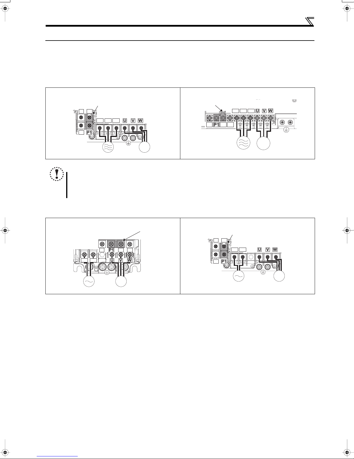
3.2 Main circuit terminal specifications
3.2.1 Terminal arrangement of the main circuit terminal, power supply and the motor
wiring
z Three-phase 400V class
FR-D740-012 to 080 FR-D740-120, 160
Jumper
-
PR
-
Jumper
+
R/L1 S/L2 T/L3
Screw size (M4)
Screw size
(M4)
IM
MotorPower supply
NOTE
y Make sure the power cables are connected to the R/L1, S/L2, T/L3. (Phase need not be matched.) Never connect the
power cable to the U, V, W of the inverter. Doing so will damage the inverter.
y Connect the motor to U, V, W. Turning on the forward rotation switch (signal) at this time rotates the motor
counterclockwise when viewed from the load shaft.
z Single-phase 200V class
FR-D720S-008 to 042 FR-D720S-070 and 100
Screw size (M3.5)
-
L1 N
+
Jumpe
-
PR
PR
+
PR
+
Screw size (M4)
R/L1 S/L2 T/L3
Jumper
Screw size (M4)
L1 N
IM
MotorPower supply
Screw size
(M4)
Screw size
(M3.5)
IM
MotorPower supply
Screw size
(M4)
IM
MotorPower supply
5
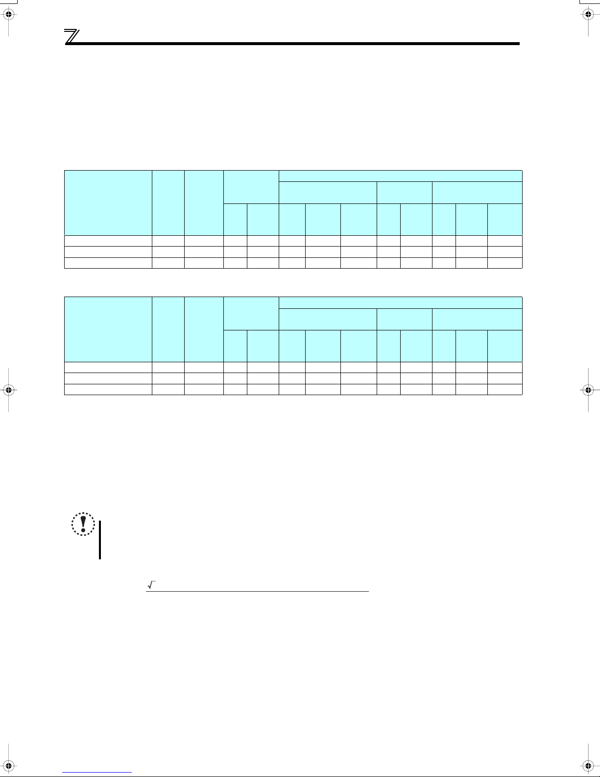
WIRING
3.2.2 Cables and wiring length
(1) Cable sizes etc., of the main control circuit terminals and earth (ground) terminals
Select the recommended cable size to ensure that a voltage drop will be 2% max.
If the wiring distance is long between the inverter and motor, a main circuit cable voltage drop will cause the motor torque to
decrease especially at the output of a low frequency.
The following table indicates a selection example for the wiring length of 20m.
Three-phase 400V class (when input power supply is 440V)
Crimping
Applicable Inverter
Model
FR-D740-012 to 080 M4 1.5 2-4 2-4 2 2 2 14 14 2.5 2.5 2.5
FR-D740-120 M4 1.5 5.5-4 2-4 3.5 2 3.5 12 14 4 2.5 4
FR-D740-160 M4 1.5 5.5-4 5.5-4 3.5 3.5 3.5 12 12 4 4 4
Ter mi nal
Screw
Size ∗4
Tightening
Torque
N·m
Ter min al
R/L1
S/L2
T/L3
U, V, W
HIV Cables, etc. (mm2) ∗1
R/L1
S/L2
T/L3
U, V, W
Earth
(ground)
cable
Cable Size
AWG ∗2
R/L1
S/L2
U, V, W
T/L3
PVC Cables, etc. (mm2)
∗3
R/L1
S/L2
T/L3
U, V, W
Earth
(ground)
cable
Single-phase 200V class (when input power supply is 220V)
Crimping
Applicable Inverter
Model
Ter mi nal
Screw
Size ∗4
Tightening
Torque
N·m
Ter min al
HIV Cables, etc. (mm2) ∗1
L1, N U, V, W L1, N U, V, W
Earth
(ground)
cable
FR-D720S-008 to 042 M3.5 1.2 2-3.5 2-3.5 2 2 2 14 14 2.5 2.5 2.5
FR-D720S-070 M4 1.5 2-4 2-4 2 2 2 14 14 2.5 2.5 2.5
FR-D720S-100 M4 1.5 5.5-4 2-4 3.5 2 3.5 12 14 4 2.5 4
∗1 The cable size is that of the cable (HIV cable (600V class 2 vinyl-insulated cable) etc.) with continuous maximum permissible temperature of 75°C. Assumes
that the surrounding air temperature is 50°C or less and the wiring distance is 20m or less.
∗2 The recommended cable size is that of the cable (THHW cable) with continuous maximum permissible temperature of 75°C. Assumes that the surrounding
air temperature is 40°C or less and the wiring distance is 20m or less.
(Selection example for use mainly in the United States.)
∗3 The recommended cable size is that of the cable (THHW cable) with continuous maximum permissible temperature of 70°C. Assumes that the surrounding
air temperature is 40°C or less and the wiring distance is 20m or less.
(Selection example for use mainly in Europe.)
∗4 The terminal screw size indicates the terminal size for R/L1, S/L2, T/L3, U, V, W, PR, +, -, P1 and a screw for earthing (grounding).
(For single-phase power input, the terminal screw size indicates the size of terminal screw for L1, N, U, V, W, and a screw for earthing (grounding).)
Cable Size
AWG ∗2
PVC Cables, etc. (mm2)
∗3
L1, N U, V, W L1, N U, V, W
Earth
(ground)
cable
NOTE
y Tighten the terminal screw to the specified torque. A screw that has been tighten too loosely can cause a short circuit
or malfunction. A screw that has been tighten too tightly can cause a short circuit or malfunction due to the unit
breakage.
y Use crimping terminals with insulation sleeve to wire the power supply and motor.
The line voltage drop can be calculated by the following formula:
line voltage drop [V]=
3 × wire resistance[mΩ/m] × wiring distance[m] × current[A]
Use a larger diameter cable when the wiring distance is long or when it is desired to decrease the voltage drop (torque
reduction) in the low speed range.
6
1000
 Loading...