

Page 1
INVERTER
FR-E700
INSTRUCTION MANUAL (Applied)
FL remote communication function
FR-E720-0.1KNF to 15KNF
OUTLINE
1
FR-E740-0.4KNF to 15KNF
WIRING
PRECAUTIONS FOR
USE OF THE INVERTER
FL REMOTE
COMMUNICATION FUNCTION
PARAMETERS
2
3
4
5
TROUBLESHOOTING
PRECAUTIONS FOR
MAINTENANCE AND INSPECTION
SPECIFICATIONS
6
7
8
Page 2
Thank you for choosing this Mitsubishi Inverter.
This Instruction Manual (Applied) provides instructions for advanced use of the FR-E700 series FL remote type
inverters. Incorrect handling might cause an unexpected fault. Before using the inverter, always read this Instruction
Manual and the Instruction Manual (Basic) [IB-0600397ENG] packed with the product carefully to use the equipment
to its optimum performance.
1. Electric Shock Prevention
This section is specifically about safety matters
Do not attempt to install, operate, maintain or inspect the
inverter until you have read through the Instruction Manual
(Basic) and appended documents carefully and can use the
equipment correctly. Do not use this product until you have
a full knowledge of the equipment, safety information and
instructions.
In this Instruction Manual, the safety instruction levels are
classified into "WARNING" and "CAUTION".
WARNING
CAUTION
CAUTION
The level may even lead to a serious
consequence according to conditions. Both instruction
levels must be followed because these are important to
personal safety.
Incorrect handling may cause
hazardous conditions, resulting in
death or severe injury.
Incorrect handling may cause
hazardous conditions, resulting in
medium or slight injury, or may cause
only material damage.
z
While power is ON or when the inverter is running, do not
open the front cover. Otherwise you may get an electric
shock.
z
Do not run the inverter with the front cover or wiring cover
removed. Otherwise you may access the exposed highvoltage terminals or the charging part of the circuitry and get
an electric shock.
z
Even if power is OFF, do not remove the front cover except
for wiring or periodic inspection. You may accidentally touch
the charged inverter circuits and get an electric shock.
z
Before wiring or inspection, power must be switched OFF. To
confirm that, LED indication of the operation panel must be
checked. (It must be OFF.) Any person who is involved in
wiring or inspection shall wait for at least 10 minutes after
the power supply has been switched OFF and check that
there are no residual voltage using a tester or the like. The
capacitor is charged with high voltage for some time after
power OFF, and it is dangerous.
z
This inverter must be earthed (grounded). Earthing
(grounding) must conform to the requirements of national
and local safety regulations and electrical code (NEC section
250, IEC 536 class 1 and other applicable standards).
A neutral-point earthed (grounded) power supply for 400V
class inverter in compliance with EN standard must be used.
z
Any person who is involved in wiring or inspection of this
equipment shall be fully competent to do the work.
z
The inverter must be installed before wiring. Otherwise you
may get an electric shock or be injured.
z
Setting dial and key operations must be performed with dry
hands to prevent an electric shock. Otherwise you may get
an electric shock.
z
Do not subject the cables to scratches, excessive stress,
heavy loads or pinching. Otherwise you may get an electric
shock.
z
Do not change the cooling fan while power is ON. It is
dangerous to change the cooling fan while power is ON.
z
Do not touch the printed circuit board or handle the cables
with wet hands. Otherwise you may get an electric shock.
z
When measuring the main circuit capacitor capacity, the DC
voltage is applied to the motor for 1s at powering OFF. Never
touch the motor terminal, etc. right after powering OFF to
prevent an electric shock.
WARNING
2. Fire Prevention
CAUTION
z
Inverter must be installed on a nonflammable wall without
holes (so that nobody touches the inverter heatsink on the
rear side, etc.). Mounting it to or near flammable material
can cause a fire.
z If the inverter has become faulty, the inverter power must
be switched OFF. A continuous flow of large current could
cause a fire.
z When using a brake resistor, a sequence that will turn OFF
power when a fault signal is output must be configured.
Otherwise the brake resistor may overheat due to damage
of the brake transistor and possibly cause a fire.
z Do not connect a resistor directly to the DC terminals P/+
and N/-. Doing so could cause a fire.
A-1
Page 3

3.Injury Prevention
CAUTION
z The voltage applied to each terminal must be the ones
specified in the Instruction Manual. Otherwise burst,
damage, etc. may occur.
z The cables must be connected to the correct terminals.
Otherwise burst, damage, etc. may occur.
z Polarity must be correct. Otherwise burst, damage, etc.
may occur.
z While power is ON or for some time after power-OFF, do
not touch the inverter as they will be extremely hot. Doing
so can cause burns.
4. Additional Instructions
Also the following points must be noted to prevent an
accidental failure, injury, electric shock, etc.
(1) Transportation and Mounting
CAUTION
z The product must be transported in correct method that
corresponds to the weight. Failure to do so may lead to
injuries.
z Do not stack the boxes containing inverters higher than
the number recommended.
z The product must be installed to the position where
withstands the weight of the product according to the
information in the Instruction Manual.
z Do not install or operate the inverter if it is damaged or
has parts missing.
z When carrying the inverter, do not hold it by the front
cover or setting dial; it may fall off or fail.
z Do not stand or rest heavy objects on the product.
z The inverter mounting orientation must be correct.
z Foreign conductive objects must be prevented from
entering the inverter. That includes screws and metal
fragments or other flammable substance such as oil.
z As the inverter is a precision instrument, do not drop or
subject it to impact.
z The inverter must be used under the following
environment. Otherwise the inverter may be damaged.
Surrounding
air
temperature
Ambient
humidity
Storage
temperature
Atmosphere
Environment
Altitude/
vibration
∗1 Temperature applicable for a short time, e.g. in transit.
-10°C to +50°C (non-freezing)
90%RH or less (non-condensing)
-20°C to +65°C *1
Indoors (free from corrosive gas, flammable gas,
oil mist, dust and dirt)
Maximum 1,000m above sea level.
2
or less at 10 to 55Hz (directions of X, Y, Z
5.9m/s
axes)
(2) Wiring
CAUTION
z Do not install a power factor correction capacitor or surge
suppressor/capacitor type filter on the inverter output
side. These devices on the inverter output side may be
overheated or burn out.
z The connection orientation of the output cables U, V, W to
the motor affects the rotation direction of the motor.
(3) Trial run
CAUTION
z Before starting operation, each parameter must be
confirmed and adjusted. A failure to do so may cause
some machines to make unexpected motions.
(4) Usage
WARNING
z Any person must stay away from the equipment when the
retry function is set as it will restart suddenly after trip.
z Since pressing key may not stop output depending
on the function setting status, separate circuit and switch
that make an emergency stop (power OFF, mechanical
brake operation for emergency stop, etc.) must be
provided.
z OFF status of the start signal must be confirmed before
resetting the inverter fault. Resetting inverter alarm with
the start signal ON restarts the motor suddenly.
The inverter must be used for three-phase induction motors.
z
Connection of any other electrical equipment to the
inverter output may damage the equipment.
z Do not modify the equipment.
Do not perform parts removal which is not instructed in this
z
manual. Doing so may lead to fault or damage of the product.
CAUTION
z
The electronic thermal relay function does not guarantee
protection of the motor from overheating. It is recommended
to install both an external thermal for overheat protection.
z Do not use a magnetic contactor on the inverter input for
frequent starting/stopping of the inverter. Otherwise the
life of the inverter decreases.
z The effect of electromagnetic interference must be
reduced by using a noise filter or by other means.
Otherwise nearby electronic equipment may be affected.
z Appropriate measures must be taken to suppress
harmonics. Otherwise power supply harmonics from the
inverter may heat/damage the power factor correction
capacitor and generator.
z When driving a 400V class motor by the inverter, the
motor must be an insulation-enhanced motor or measures
must be taken to suppress surge voltage. Surge voltage
attributable to the wiring constants may occur at the
motor terminals, deteriorating the insulation of the motor.
z When parameter clear or all parameter clear is performed,
the required parameters must be set again before starting
operations because all parameters return to the initial value.
z The inverter can be easily set for high-speed operation.
Before changing its setting, the performances of the
motor and machine must be fully examined.
z Stop status cannot be hold by the inverter's brake
function. In addition to the inverter’s brake function, a
holding device must be installed to ensure safety.
z Before running an inverter which had been stored for a long
period, inspection and test operation must be performed.
z For prevention of damage due to static electricity, nearby
metal must be touched before touching this product to
eliminate static electricity from your body.
A-2
Page 4
(5) Emergency stop
CAUTION
z A safety backup such as an emergency brake must be
provided to prevent hazardous condition to the machine
and equipment in case of inverter failure.
z When the breaker on the inverter input side trips, the
wiring must be checked for fault (short circuit), and
internal parts of the inverter for a damage, etc. The cause
of the trip must be identified and removed before turning
ON the power of the breaker.
z When any protective function is activated, appropriate
corrective action must be taken, and the inverter must be
reset before resuming operation.
(6) Maintenance, inspection and parts replacement
CAUTION
z Do not carry out a megger (insulation resistance) test on
the control circuit of the inverter. It will cause a failure.
(7) Disposal
CAUTION
z The inverter must be treated as industrial waste.
General instruction
Many of the diagrams and drawings in this Instruction
Manual show the inverter without a cover or partially open
for explanation. Never operate the inverter in this manner.
The cover must be always reinstalled and the instruction in
this Instruction Manual must be followed when operating
the inverter.
A-3
Page 5

CONTENTS
1 OUTLINE 1
1.1 Product checking and parts identification......................................... 2
1.2 Inverter and peripheral devices ......................................................... 3
1.2.1 Peripheral devices .......................................................................................................................... 4
1.3 Removal and reinstallation of the cover ............................................ 5
1.3.1 Front cover...................................................................................................................................... 5
1.3.2 Wiring cover.................................................................................................................................... 7
1.4 Installation of the inverter and enclosure design.............................. 8
1.4.1 Inverter installation environment..................................................................................................... 8
1.4.2 Cooling system types for inverter enclosure................................................................................. 10
1.4.3 Inverter placement ........................................................................................................................ 11
2 WIRING 13
2.1 Wiring ................................................................................................ 14
2.1.1 Terminal connection diagram ....................................................................................................... 14
2.2 Main circuit terminal specifications ................................................ 15
2.2.1 Specification of main circuit terminal ............................................................................................ 15
2.2.2 Terminal arrangement of the main circuit terminal, power supply and the motor wiring............... 15
2.2.3 Cables and wiring length .............................................................................................................. 17
2.3 Control circuit specifications ........................................................... 20
2.3.1 Control circuit terminal .................................................................................................................. 20
2.3.2 Wiring of control circuit ................................................................................................................. 21
2.3.3 Connecting the 24V external power supply .................................................................................. 23
2.3.4 Safety stop function ...................................................................................................................... 24
2.4 Connection of stand-alone option unit ............................................. 25
2.4.1 Connection of a dedicated external brake resistor (MRS type, MYS type, FR-ABR) ................... 25
2.4.2 Connection of the brake unit (FR-BU2) ........................................................................................ 27
2.4.3 Connection of the DC reactor (FR-HEL)....................................................................................... 28
3 PRECAUTIONS FOR USE OF THE INVERTER 29
3.1 EMC and leakage currents................................................................ 30
3.1.1 Leakage currents and countermeasures ...................................................................................... 30
3.1.2 EMC measures ............................................................................................................................. 32
3.1.3 Power supply harmonics............................................................................................................... 34
3.1.4 Harmonic suppression guideline in Japan ....................................................................................35
I
Page 6

3.2 Installation of power factor improving reactor ................................ 37
3.3 Power-OFF and magnetic contactor (MC)......................................... 38
3.4 Inverter-driven 400V class motor ..................................................... 39
3.5 Precautions for use of the inverter ................................................... 40
3.6 Failsafe of the system which uses the inverter ............................... 42
4 FL REMOTE COMMUNICATION FUNCTION 45
4.1 FL remote communication specification.......................................... 46
4.2 Node address setting ........................................................................46
4.3 Wiring .................................................................................................47
4.3.1 Connecting to the network ............................................................................................................ 47
4.3.2 Precautions for system configuration ........................................................................................... 47
4.3.3 Cable specifications...................................................................................................................... 47
4.3.4 Connecting the FL-net dedicated cable........................................................................................ 48
CONTENTS
4.4 LED status ......................................................................................... 49
4.4.1 Device status LED (DEV), remote status LED (RMT) .................................................................. 49
4.4.2 Transmitting (TX)/receiving (RX) LED .......................................................................................... 49
4.4.3 Communication set status LED (CHG).........................................................................................49
4.5 Operation mode setting.....................................................................50
4.5.1 Operation mode basics................................................................................................................. 50
4.5.2 PU operation interlock .................................................................................................................. 51
4.5.3 Operation availability in each operation mode..............................................................................51
4.6 FL remote communication ................................................................ 52
4.6.1 Overview of FL remote communication ........................................................................................52
4.6.2 FL remote data communication types .......................................................................................... 52
4.7 Cyclic transmission ........................................................................... 53
4.7.1 Common memory ......................................................................................................................... 54
4.7.2 Output data (master to inverter) ................................................................................................... 57
4.7.3 Input data (inverter to master) ...................................................................................................... 59
4.8 Message transmission.......................................................................61
4.8.1 Error response at word block read/write ....................................................................................... 61
4.8.2 Word block read/write ................................................................................................................... 62
4.8.3 Network parameter read ............................................................................................................... 68
4.8.4 Log data read ............................................................................................................................... 69
4.8.5 Log data clear............................................................................................................................... 69
4.8.6 Profile read ................................................................................................................................... 70
4.8.7 Message loopback........................................................................................................................ 71
II
Page 7

5 PARAMETERS 73
5.1 Operation panel................................................................................. 74
5.1.1 Names and functions of the operation panel ................................................................................ 74
5.1.2 Basic operation (factory setting) ................................................................................................... 75
5.1.3 Changing the parameter setting value.......................................................................................... 76
5.1.4 Setting dial push ........................................................................................................................... 77
5.2 Parameter list ................................................................................... 78
5.2.1 Parameter list................................................................................................................................ 78
5.3 Control mode.................................................................................... 92
5.3.1 Changing the control method (Pr. 80, Pr. 81, Pr. 800) ................................................................ 93
5.4 Adjustment of the output torque (current) of the motor................. 94
5.4.1 Manual torque boost (Pr. 0, Pr. 46) ............................................................................................. 94
5.4.2 Advanced magnetic flux vector control (Pr. 71, Pr. 80, Pr. 81, Pr.89, Pr. 800) .......................... 95
5.4.3 General-purpose magnetic flux vector control (Pr. 71, Pr. 80, Pr. 81, Pr. 800) ........................... 98
5.4.4 Slip compensation (Pr. 245 to Pr. 247) ..................................................................................... 100
5.4.5 Stall prevention operation (Pr. 22, Pr. 23, Pr. 48, Pr. 66, Pr. 156, Pr. 157, Pr. 277) ................. 101
5.5 Limiting the output frequency ....................................................... 105
5.5.1 Maximum/minimum frequency (Pr. 1, Pr. 2, Pr. 18)................................................................... 105
5.5.2 Avoiding mechanical resonance points (frequency jumps) (Pr. 31 to Pr. 36) ............................ 106
5.6 V/F pattern...................................................................................... 107
5.6.1 Base frequency, voltage (Pr. 3, Pr. 19, Pr. 47) .......................................................................... 107
5.6.2 Load pattern selection (Pr. 14) .................................................................................................. 109
5.7 Frequency setting by input signals ............................................... 111
5.7.1 Operation by multi-speed operation (Pr. 4 to Pr. 6, Pr. 24 to Pr. 27) ......................................... 111
5.7.2 Remote setting function (Pr. 59)................................................................................................ 113
5.8 Setting of acceleration/deceleration time and acceleration/
deceleration pattern ...................................................................... 116
5.8.1 Setting of the acceleration and deceleration time
(Pr. 7, Pr. 8, Pr. 20, Pr. 21, Pr. 44, Pr. 45, Pr. 147) .................................................................. 116
5.8.2 Starting frequency and start-time hold function (Pr. 13, Pr. 571)............................................... 119
5.8.3 Acceleration/deceleration pattern (Pr. 29) ................................................................................. 120
5.8.4 Shortest acceleration/deceleration (automatic acceleration/deceleration)
(Pr. 61 to Pr. 63, Pr. 292, Pr. 293)............................................................................................. 121
5.9 Selection and protection of a motor ............................................. 123
5.9.1 Motor overheat protection (Electronic thermal O/L relay) (Pr. 9, Pr. 51) ................................... 123
5.9.2 Applied motor (Pr. 71, Pr. 450).................................................................................................. 125
5.9.3 Exhibiting the best performance for the motor (offline auto tuning)
(Pr. 71, Pr. 80 to Pr. 84, Pr. 90 to Pr. 94, Pr. 96, Pr. 859) ......................................................... 127
III
Page 8

5.10 Motor brake and stop operation..................................................... 135
5.10.1 DC injection brake (Pr. 10 to Pr. 12).......................................................................................... 135
5.10.2 Selection of a regenerative brake (Pr. 30, Pr. 70) ..................................................................... 136
5.10.3 Stop selection (Pr. 250) ............................................................................................................. 138
5.10.4 Stop-on contact control function (Pr. 6, Pr. 48, Pr. 270, Pr. 275, Pr. 276) ................................ 139
5.11 I/O signal control ............................................................................ 141
5.11.1 Operation of start signals (STF, STR signal)............................................................................. 141
5.11.2 Reset cancel signal (READY signal) and inverter running signal (RUN signal) ........................ 142
5.11.3 Second function selection signal (RT signal)............................................................................. 143
5.11.4 Inverter output shutoff signal (MRS signal, Pr. 17).................................................................... 143
5.11.5 Detection of output frequency (SU, FU signal, Pr. 41 to Pr. 43) ................................................ 144
5.11.6 Output current detection function (Y12 signal, Y13 signal, Pr. 150 to Pr. 153) ......................... 145
5.12 Monitor display and monitor output signal .................................... 146
5.12.1 Speed display and speed setting (Pr. 37).................................................................................. 146
5.12.2 Monitor display selection of the operation panel
(Pr. 52, Pr. 170, Pr. 171, Pr. 268, Pr. 563, Pr. 564)................................................................... 147
CONTENTS
5.13 Operation selection at power failure and instantaneous power
failure.............................................................................................. 151
5.13.1 Automatic restart after instantaneous power failure/flying start
(Pr. 57, Pr. 58, Pr. 96, Pr. 162, Pr. 165, Pr. 298, Pr. 299, Pr. 611) ........................................... 151
5.13.2 Power-failure deceleration stop function (Pr. 261) .................................................................... 156
5.14 Operation setting at fault occurrence ........................................... 158
5.14.1 Retry function (Pr. 65, Pr. 67 to Pr. 69) ..................................................................................... 158
5.14.2 Input/output phase loss protection selection (Pr. 251, Pr. 872) ................................................. 160
5.14.3 Earth (ground) fault detection at start (Pr. 249) ......................................................................... 160
5.14.4 Display and erasure of communication error occurrence count (Pr. 501) ................................. 161
5.15 Energy saving operation................................................................. 162
5.15.1 Optimum excitation control (Pr. 60) ........................................................................................... 162
5.16 Motor noise, EMI measures, mechanical resonance .................... 163
5.16.1 PWM carrier frequency and soft-PWM control (Pr. 72, Pr. 240)................................................ 163
5.16.2 Speed smoothing control (Pr. 653)............................................................................................ 164
5.17 Misoperation prevention and parameter setting restriction......... 165
5.17.1 Reset selection/PU stop selection (Pr. 75) ................................................................................ 165
5.17.2 Parameter write disable selection (Pr. 77)................................................................................. 166
5.17.3 Reverse rotation prevention selection (Pr. 78) .......................................................................... 167
5.17.4 Extended parameter display and user group function (Pr. 160, Pr. 172 to Pr. 174) .................. 167
5.17.5 Password function (Pr. 296, Pr. 297)......................................................................................... 169
5.18 Special operation and frequency control ...................................... 171
5.18.1 Jog operation (Pr. 15, Pr. 16) .................................................................................................... 171
IV
Page 9

5.18.2 Droop control (Pr. 286, Pr. 287) ................................................................................................ 173
5.18.3 Regeneration avoidance function (Pr. 665, Pr. 882, Pr. 883, Pr. 885, Pr. 886)......................... 174
5.19 Useful functions ............................................................................. 176
5.19.1 Cooling fan operation selection (Pr. 244) .................................................................................. 176
5.19.2 Display of the life of the inverter parts (Pr. 255 to Pr. 259)........................................................ 177
5.19.3 Maintenance timer alarm (Pr. 503, Pr. 504)............................................................................... 180
5.19.4 Free parameter (Pr. 888, Pr. 889) ............................................................................................. 181
5.20 Setting from the operation panel .................................................. 182
5.20.1 RUN key rotation direction selection (Pr. 40)............................................................................. 182
5.20.2 Operation panel frequency setting/key lock operation selection (Pr. 161)................................. 183
5.20.3 Magnitude of frequency change setting (Pr. 295)...................................................................... 185
5.21 Parameter clear/ All parameter clear ............................................ 186
5.22 Initial value change list ................................................................. 187
5.23 Check and clear of the faults history ............................................ 188
6 TROUBLESHOOTING 191
6.1 Reset method of protective function ............................................. 192
6.2 List of fault or alarm indications .................................................... 193
6.3 Causes and corrective actions....................................................... 194
6.4 Correspondences between digital and actual characters ............ 203
6.5 Check first when you have a trouble.............................................. 204
6.5.1 Motor does not start.................................................................................................................... 204
6.5.2 Motor or machine is making abnormal acoustic noise................................................................ 205
6.5.3 Inverter generates abnormal noise............................................................................................. 205
6.5.4 Motor generates heat abnormally............................................................................................... 206
6.5.5 Motor rotates in the opposite direction........................................................................................ 206
6.5.6 Speed greatly differs from the setting......................................................................................... 206
6.5.7 Acceleration/deceleration is not smooth ..................................................................................... 206
6.5.8 Speed varies during operation .................................................................................................... 207
6.5.9 Operation mode is not changed properly.................................................................................... 207
6.5.10 Operation panel display is not operating .................................................................................... 207
6.5.11 Motor current is too large............................................................................................................ 208
6.5.12 Speed does not accelerate......................................................................................................... 208
6.5.13 Unable to write parameter setting............................................................................................... 208
6.5.14 Troubleshooting in FL remote communication............................................................................ 209
7 PRECAUTIONS FOR MAINTENANCE AND INSPECTION 211
V
Page 10

7.1 Inspection items.............................................................................. 212
7.1.1 Daily inspection .......................................................................................................................... 212
7.1.2 Periodic inspection ..................................................................................................................... 212
7.1.3 Daily and periodic inspection...................................................................................................... 213
7.1.4 Display of the life of the inverter parts ........................................................................................ 214
7.1.5 Checking the inverter and converter modules ............................................................................ 214
7.1.6 Cleaning ..................................................................................................................................... 214
7.1.7 Replacement of parts ................................................................................................................. 215
7.2 Measurement of main circuit voltages, currents and powers ....... 218
7.2.1 Measurement of powers ............................................................................................................. 220
7.2.2 Measurement of voltages and use of PT.................................................................................... 220
7.2.3 Measurement of currents............................................................................................................ 221
7.2.4 Use of CT and transducer .......................................................................................................... 221
7.2.5 Measurement of inverter input power factor ............................................................................... 221
7.2.6 Measurement of converter output voltage (across terminals P and N) ...................................... 221
7.2.7 Insulation resistance test using megger ..................................................................................... 222
7.2.8 Pressure test .............................................................................................................................. 222
CONTENTS
8 SPECIFICATIONS 223
8.1 Rating............................................................................................... 224
8.2 Common specifications................................................................... 225
8.3 Outline dimension drawings............................................................ 226
APPENDIX 231
Appendix 1 Specification change ................................................................................ 232
Appendix 1-1 SERIAL number check .................................................................................................... 232
Appendix 1-2 Changed Functions ......................................................................................................... 232
Appendix 2 Index........................................................................................................... 233
VI
Page 11

MEMO
VII
Page 12

1 OUTLINE
This chapter explains the "OUTLINE" for use of this product.
Always read the instructions before using the equipment.
1.1 Product checking and parts identification ................................. 2
1.2 Inverter and peripheral devices................................................... 3
1.3 Removal and reinstallation of the cover ..................................... 5
1.4 Installation of the inverter and enclosure design ...................... 8
<Abbreviation>
Inverter ........................................... Mitsubishi inverter FR-E700 series FL remote type
FR-E700-NF .................................. Mitsubishi inverter FR-E700 series FL remote type
Pr.................................................... Parameter number
PU operation .................................. Operation using the operation panel
Mitsubishi standard motor .............. SF-JR
Mitsubishi constant-torque motor ... SF-HRCA
<Trademark>
Company and product names herein are the trademarks and registered trademarks of their
respective owners.
<Mark>
1
2
3
4
REMARKS :Additional helpful contents and relations with other functions are stated
NOTE :Contents requiring caution or cases when set functions are not
activated are stated.
POINT :Useful contents and points are stated.
Parameters referred to : Related parameters are stated.
5
6
7
8
1
Page 13
Product checking and parts identification
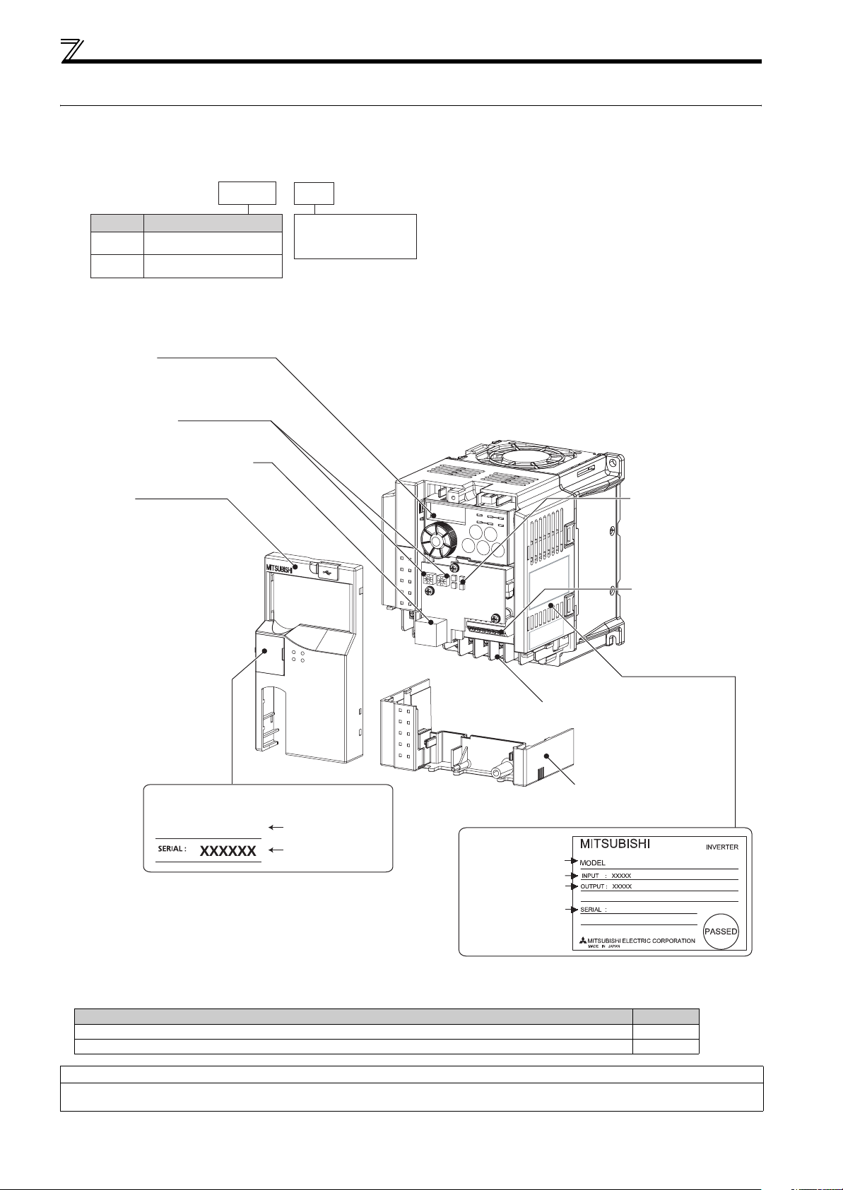
1.1 Product checking and parts identification
Unpack the inverter and check the capacity plate on the front cover and the rating plate on the inverter side face to ensure that
the product agrees with your order and the inverter is intact.
zInverter model
--
E720 2.2 KNFFR
No. Voltage class
E720
E740
Operation panel
(Refer to page 74)
Node address switch
(Refer to page 46)
FL remote communication connector
(Refer to page 48)
Front cover
(Refer to page 5)
Three-phase 200V class
Three-phase 400V class
Represents the
inverter capacity [kW]
Cooling fan
(Refer to page 215)
LED (operation status
indication)
(Refer to page 49)
Control circuit terminal
block
(Refer to page 20)
Main circuit terminal block
(Refer to page 15)
Capacity plate *
FR-E720-2.2KNF
Inverter model
Example of FR-E720-2.2KNF
Serial number
∗ Location of the capacity plate and the rating plate differs
according to the inverter capacity.
Refer to the outline dimension drawing. (Refer to page 226)
Rating plate *
Inverter model
Input rating
Output rating
Serial number
Combed shaped wiring cover
(Refer to page 7)
FR-E720-2.2KNF
• Accessory
· Fan cover fixing screws (M3 × 35mm)
These screws are necessary for compliance with the EU Directive (
Capacity Quantity
FR-E720-1.5KNF to 3.7KNF, FR-E740-1.5KNF to 3.7KNF 1
FR-E720-5.5KNF to 15KNF, FR-E740-5.5KNF to 15KNF 2
Harmonic suppression guideline (when inverters are used in Japan)
All models of general-purpose inverters used by specific consumers are covered by "Harmonic suppression guideline for consumers who
receive high voltage or special high voltage". (For further details, refer to page 35.)
Refer to the Instruction Manual (Basic)
)
2
Page 14
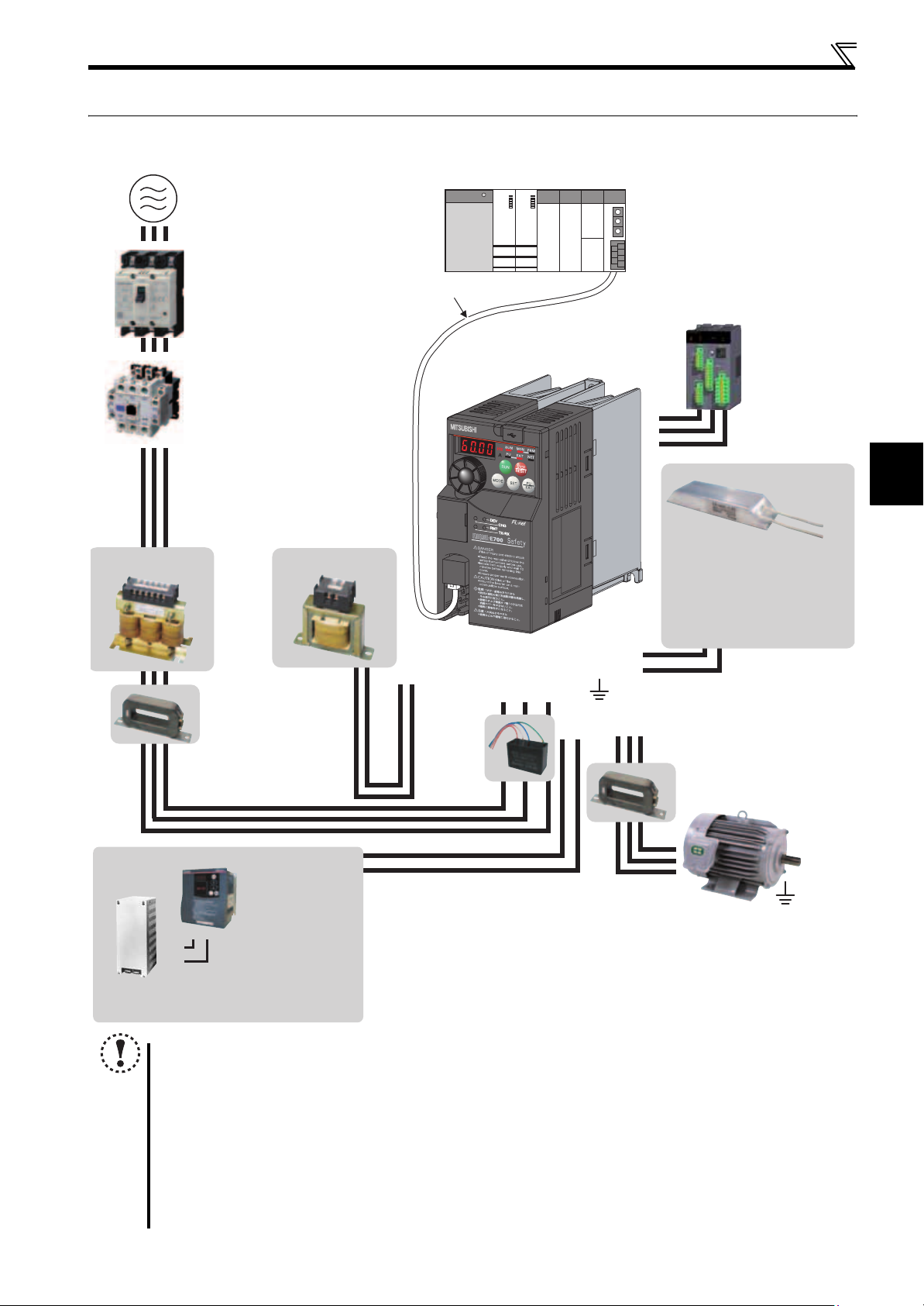
1.2 Inverter and peripheral devices
AC power supply
AC reactor (FR-HAL)
Use within the permissible power supply
specifications of the inverter. To ensure
safety, use a moulded case circuit breaker,
earth leakage circuit breaker or magnetic
contactor to switch power ON/OFF.
(Refer to page 224)
Moulded case circuit breaker
(MCCB) or earth leakage circuit
breaker (ELB), fuse
The breaker must be selected carefully
since an in-rush current flows in the
inverter at power on.
Magnetic contactor (MC)
Install the magnetic contactor to ensure
safety. Do not use this magnetic contactor
to start and stop the inverter. Doing so will
cause the inverter life to be shorten.
(Refer to page 38)
Reactor (FR-HAL, FR-HEL option)
Reactors (option) must be used when
power harmonics measures are taken,
the power factor is to be improved or the
inverter is installed near a large power
supply system (500kVA or more). The
inverter may be damaged if you do not
use reactors. Select the reactor according
to the model. Remove the jumpers across
terminals P/+ and P1 to connect the DC reactor.
EMC filter (ferrite core) *
(FR-BSF01, FR-BLF)
Install an EMC filter (ferrite core)
to reduce the electromagnetic
noise generated from the
inverter. Effective in the range
from about 1MHz to 10MHz.
When more wires are passed
through, a more effective result
can be obtained. A wire should
be wound four turns or more.
(Refer to page 4)
DC reactor (FR-HEL) *
Master module
FL-net dedicated cable
Inverter (FR-E700-NF)
P1P/+
EMC filter
(capacitor) *
(FR-BIF)
Reduces the
radio noise.
Inverter and peripheral devices
R/L1 S/L2T/L3
P/+
PR
Earth (Ground)
UW
N/-P/+
V
Approved safety
relay module
Required for
compliance with
safety standard.
S1
S2
PC
Brake resistor
(FR-ABR, MRS type, MYS type)
Braking capability can be improved.
(0.4K or higher)
Always install a thermal relay when
using a brake resistor whose capacity
is 11K or higher.
EMC filter (ferrite core)
(FR-BSF01, FR-BLF)
Install
to reduce the electromagnetic
noise generated from the inverter.
Effective in the range from about
1MHz to 10MHz. A wire should be
wound four turns at a maximum.
(Refer to page 25)
an EMC filter (ferrite core)
1
OUTLINE
Motor
* Filterpack (FR-BFP2), which contains DC reactor and EMC filter in one package, is also available.
Brake unit
(FR-BU2)
The regenerative
braking capability
of the inverter can be
PR
P/+
P/+
PR
Resistor unit (FR-BR)
Discharging resistor (GZG, GRZG)
exhibited fully.
Install this as required.
Devices connected to the output
Do not install a power factor correction
capacitor, surge suppressor or capacitor type
filter on the output side of the inverter.
When installing a moulded case circuit breaker
on the output side of the inverter, contact each
manufacturer for selection of the moulded case
circuit breaker.
NOTE
Up to 64 inverters can be connected when using FL remote communication.
The life of the inverter is influenced by surrounding air temperature. The surrounding air temperature should be as low as
possible within the permissible range. This must be noted especially when the inverter is installed in an enclosure. (Refer
to page 8)
y Wrong wiring might lead to damage of the inverter. The control signal lines must be kept fully away from the main circuit
to protect them from noise. (Refer to page 14)
Do not install a power factor correction capacitor, surge suppressor or capacitor type filter on the inverter output side.
This will cause the inverter to trip or the capacitor and surge suppressor to be damaged. If any of the above devices are
connected, immediately remove them.
Electromagnetic wave interference
The input/output (main circuit) of the inverter includes high frequency components, which may interfere with the
communication devices (such as AM radios) used near the inverter. In this case, install options among the capacitor type
EMC filter FR-BIF (for use in the input side only), the ferrite core type EMC filter FR-BSF01/FR-BLF, filterpack, and EMC
filter to minimize the interference. (Refer to page 32).
Refer to the instruction manual of each option and peripheral devices for details of peripheral devices.
Earth (Ground)
To prevent an electric shock, always earth
(ground) the motor and inverter. For reduction of
induction noise from the power line of the
inverter, it is recommended to wire the earth
(ground) cable by returning it to the earth
(ground) terminal of the inverter.
Earth (Ground)
3
Page 15
Inverter and peripheral devices
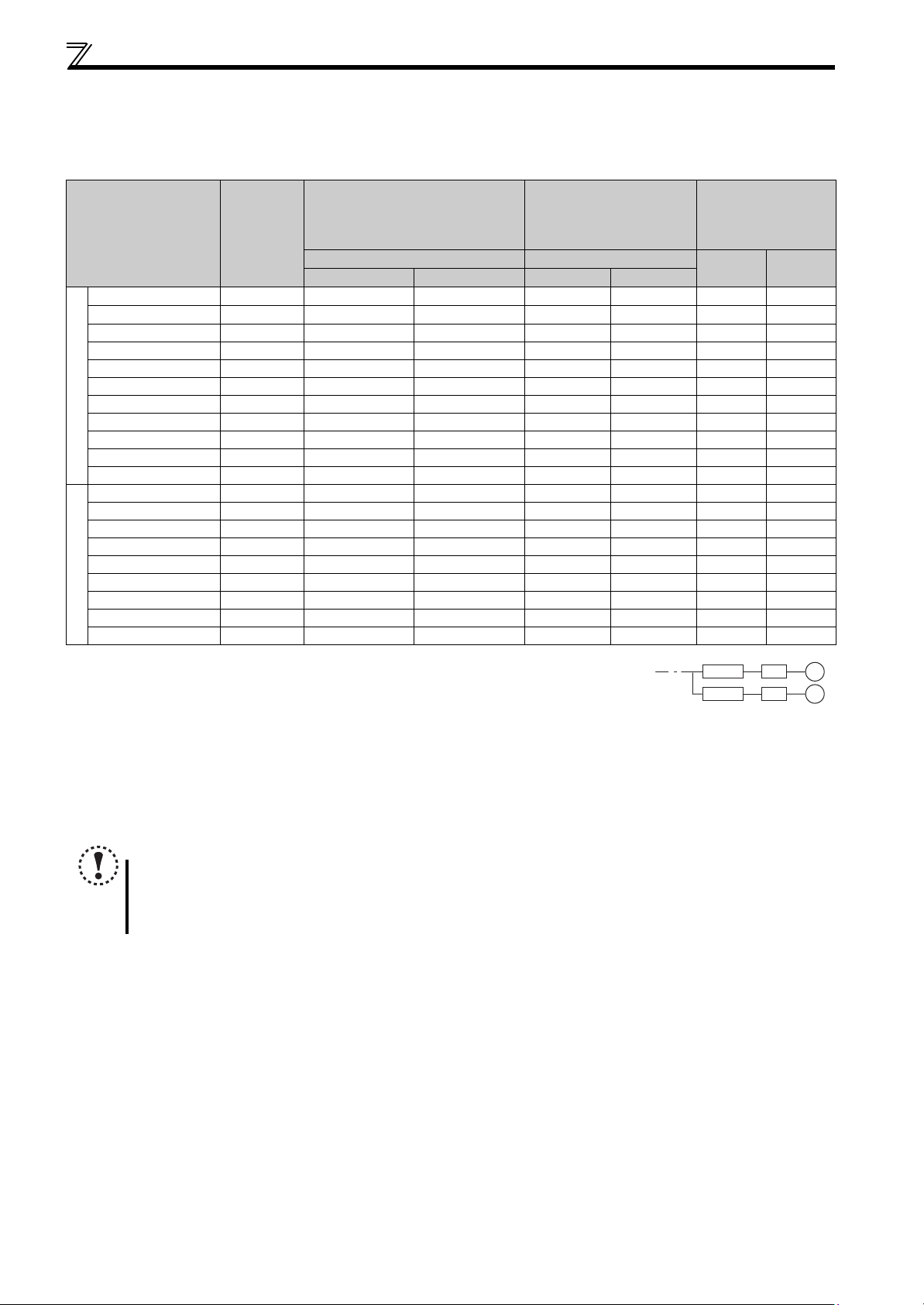
1.2.1 Peripheral devices
Check the inverter model of the inverter you purchased. Appropriate peripheral devices must be selected according to the capacity.
Refer to the following list and prepare appropriate peripheral devices:
Moulded Case Circuit Breaker
(MCCB) ∗1
(ELB) ∗2 (NF, NV type)
Reactor connection Reactor connection
Applicable Inverter
Model
Motor
Output
(kW)
or Earth Leakage Circuit Breaker
without with without with
FR-E720-0.1KNF 0.1 5A 5A S-N10 S-N10 0.4K ∗4
FR-E720-0.2KNF 0.2 5A 5A S-N10 S-N10 0.4K ∗4
FR-E720-0.4KNF 0.4 5A 5A S-N10 S-N10 0.4K 0.4K
FR-E720-0.75KNF 0.75 10A 10A S-N10 S-N10 0.75K 0.75K
FR-E720-1.5KNF 1.5 15A 15A S-N10 S-N10 1.5K 1.5K
FR-E720-2.2KNF 2.2 20A 15A S-N10 S-N10 2.2K 2.2K
FR-E720-3.7KNF 3.7 30A 30A S-N20, S-N21 S-N10 3.7K 3.7K
FR-E720-5.5KNF 5.5 50A 40A S-N25 S-N20, S-N21 5.5K 5.5K
Three-Phase 200V
FR-E720-7.5KNF 7.5 60A 50A S-N25 S-N25 7.5K 7.5K
FR-E720-11KNF 11 75A 75A S-N35 S-N35 11K 11K
FR-E720-15KNF 15 125A 100A S-N50 S-N50 15K 15K
FR-E740-0.4KNF 0.4 5A 5A S-N10 S-N10 H0.4K H0.4K
FR-E740-0.75KNF 0.75 5A 5A S-N10 S-N10 H0.75K H0.75K
FR-E740-1.5KNF 1.5 10A 10A S-N10 S-N10 H1.5K H1.5K
FR-E740-2.2KNF 2.2 15A 10A S-N10 S-N10 H2.2K H2.2K
FR-E740-3.7KNF 3.7 20A 15A S-N10 S-N10 H3.7K H3.7K
FR-E740-5.5KNF 5.5 30A 20A S-N20, S-N21 S-N11, S-N12 H5.5K H5.5K
FR-E740-7.5KNF 7.5 30A 30A S-N20, S-N21 S-N20, S-N21 H7.5K H7.5K
Three-Phase 400V
FR-E740-11KNF 11 50A 40A S-N20, S-N21 S-N20, S-N21 H11K H11K
FR-E740-15KNF 15 60A 50A S-N25 S-N20, S-N21 H15K H15K
Magnetic Contactor (MC)
∗3
Reactor
FR-HAL FR-HEL
0.4K
0.4K
∗4
∗4
∗1 Select an MCCB according to the power supply capacity.
Install one MCCB per inverter.
∗2 For the use in the United States or Canada, select a UL and cUL certified fuse with Class T fuse equivalent cut-off
speed or faster with the appropriate rating for branch circuit protection. Alternatively, select a UL489 molded case circuit breaker (MCCB).
∗3 Magnetic contactor is selected based on the AC-1 class. The electrical durability of magnetic contactor is 500,000 times. When the magnetic contactor is
used for emergency stop during motor driving, the electrical durability is 25 times.
When using the MC for emergency stop during motor driving or using on the motor side during commercial-power supply operation, select the MC with class
AC-3 rated current for the motor rated current.
∗4 The power factor may be slightly lower.
MCCB INV
MCCB INV
IM
IM
NOTE
When the inverter capacity is larger than the motor capacity, select an MCCB and a magnetic contactor according to
the inverter model and cable and reactor according to the motor output.
When the breaker on the inverter input side trips, check for the wiring fault (short circuit), damage to internal parts of
the inverter, etc. Identify the cause of the trip, then remove the cause and power on the breaker.
4
Page 16
Removal and reinstallation of the cover
1.3 Removal and reinstallation of the cover
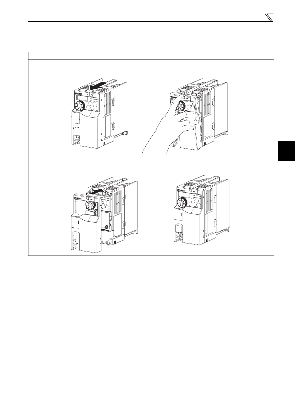
1.3.1 Front cover
FR-E720-3.7KNF or lower, FR-E740-7.5KNF or lower
zRemoval (Example of FR-E720-0.75KNF)
Remove the front cover by pulling it toward you in the direction of arrow.
1
zReinstallation (Example of FR-E720-0.75KNF)
To reinstall, match the cover to the inverter front and install it straight.
OUTLINE
5
Page 17
Removal and reinstallation of the cover
r
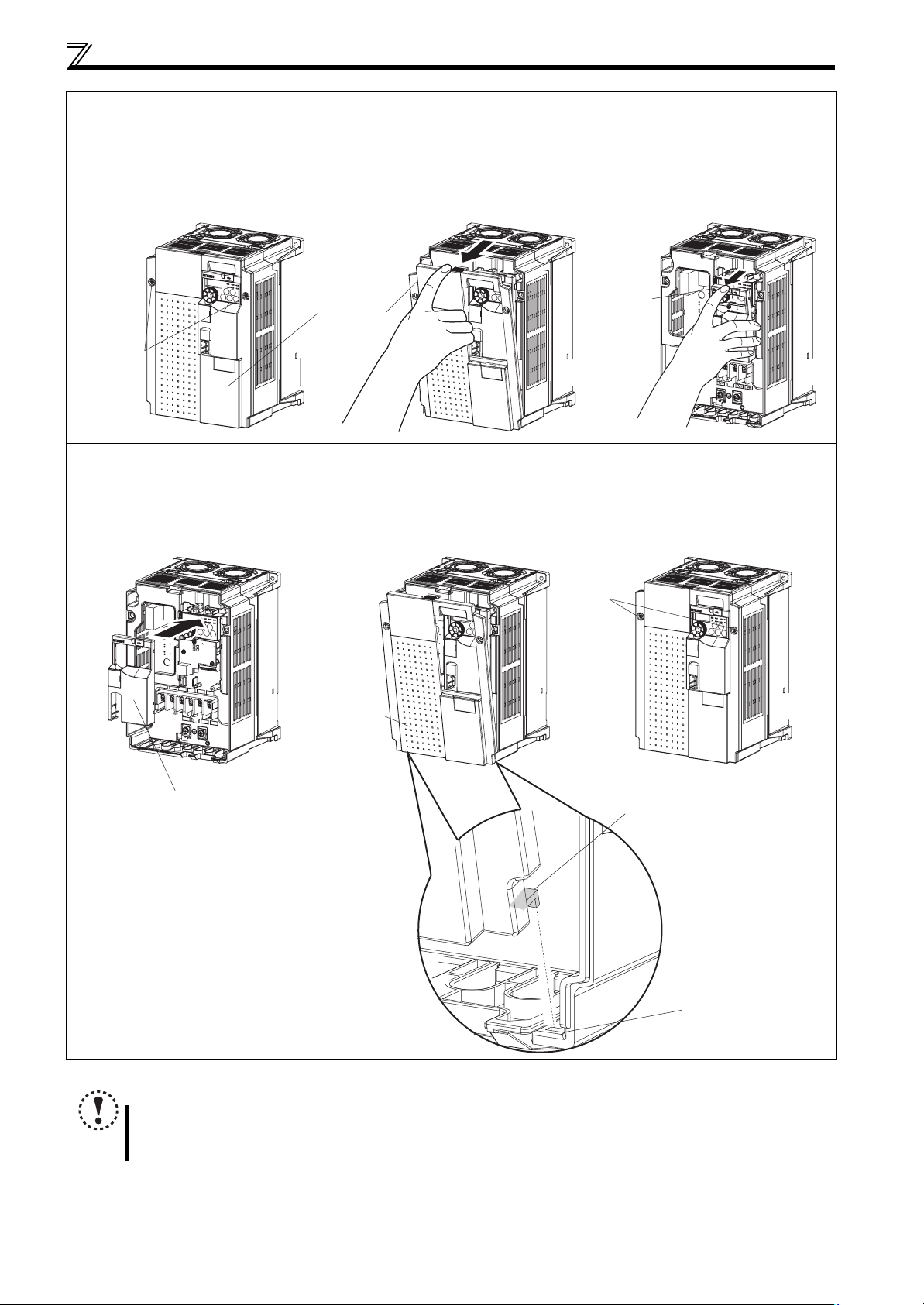
FR-E720-5.5KNF or higher, FR-E740-11KNF or higher
zRemoval (Example of FR-E720-5.5KNF)
1) Loosen the installation screws of the front cover 1.
2) Remove the front cover 1 by pulling it toward you in the direction of arrow.
3) Remove the front cover 2 by pulling it toward you in the direction of arrow.
1) 2) 3)
Front cover 2
Front cover 1
Installation
screws
zReinstallation (Example of FR-E720-5.5KNF)
1) Match the front cover 2 to the inverter front and install it straight.
2) Insert the two fixed hooks on the lower side of the front cover 1 into the sockets of the inverter.
3)Tighten the screw of the front cover 1.
1) 2) 3)
Tighten
the installation
screws
Front cover 1
Front cover 2
Fixed hook
Socket of the inverte
NOTE
Fully make sure that the front cover has been reinstalled securely.
The same serial number is printed on the capacity plate of the front cover and the rating plate of the inverter. Since
these plates have the same serial numbers, always reinstall the removed cover onto the original inverter.
6
Page 18
Removal and reinstallation of the cover
r
r
e
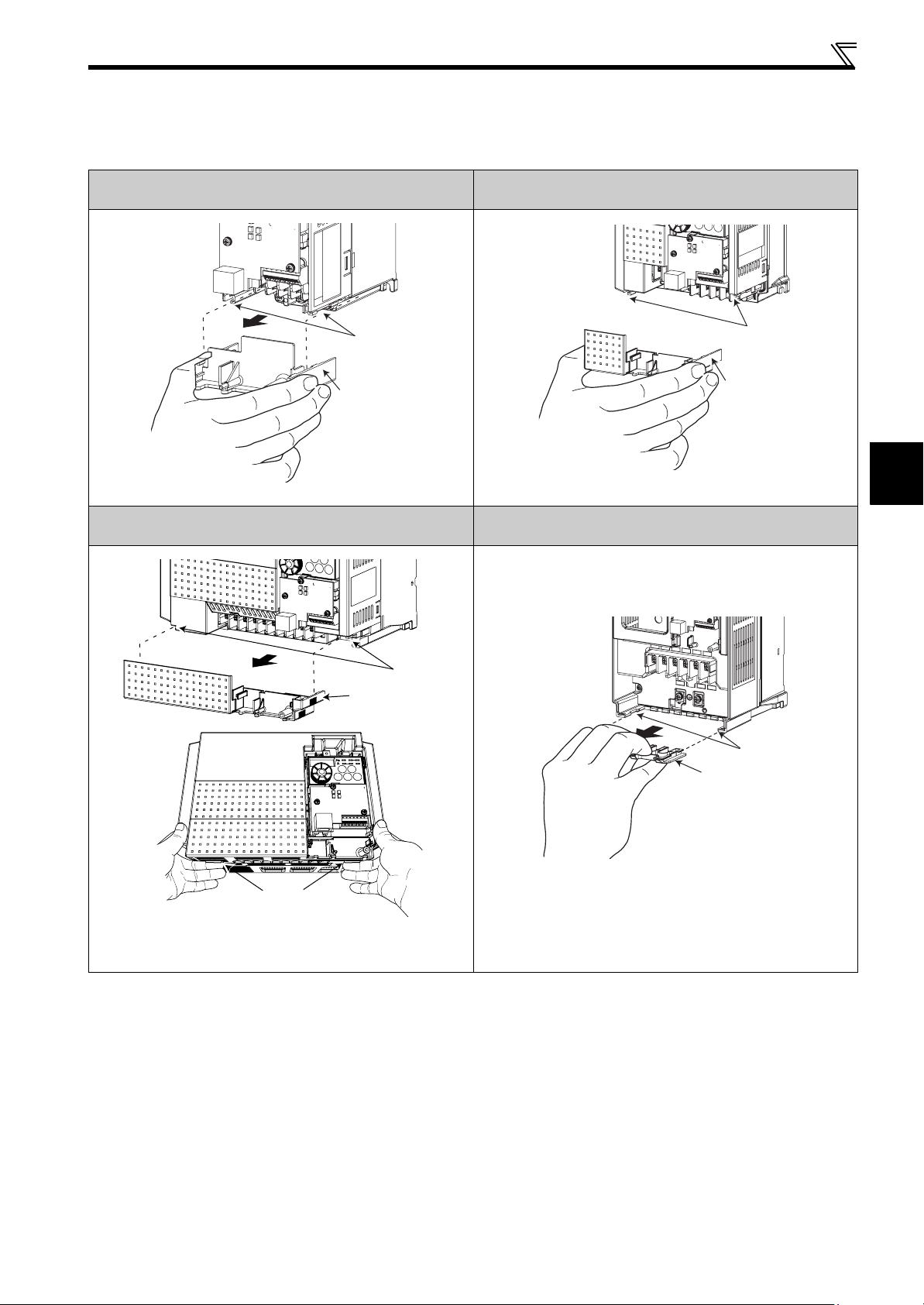
1.3.2 Wiring cover
zRemoval and reinstallation
The cover can be removed easily by pulling it toward you. To reinstall, fit the cover to the inverter along the guides.
FR-E720-0.1KNF to 0.75KNF
Guide
Wiring cove
Example of FR-E720-0.75KNF Example of FR-E740-3.7KNF
FR-E740-5.5KNF, 7.5KNF
FR-E720-1.5KNF to 3.7KNF
FR-E740-0.4KNF to 3.7KNF
Wiring cove
FR-E720-5.5KNF to 15KNF
FR-E740-11KNF, 15KNF
Guide
1
OUTLINE
Guid
Wiring cover
Dent
For removal, push the dent on the wiring cover with your finger and
pull toward you.
Example of FR-E740-5.5KNF Example of FR-E740-11KNF
Guide
Wiring cover
7
Page 19

Installation of the inverter and enclosure design
1.4 Installation of the inverter and enclosure design
When an inverter enclosure is to be designed and manufactured, heat generated by contained equipment, etc., the
environment of an operating place, and others must be fully considered to determine the enclosure structure, size and
equipment layout. The inverter unit uses many semiconductor devices. To ensure higher reliability and long period of
operation, operate the inverter in the ambient environment that completely satisfies the equipment specifications.
1.4.1 Inverter installation environment
As the inverter installation environment should satisfy the standard specifications indicated in the following table, operation in
any place that does not meet these conditions not only deteriorates the performance and life of the inverter, but also causes a
failure. Refer to the following points and take adequate measures.
Environmental standard specifications of inverter
Item Description
Surrounding air
temperature
Ambient humidity 90%RH or less (non-condensing)
Atmosphere Free from corrosive and explosive gases, free from dust and dirt
Maximum altitude 1,000m or less
Vibration
(1) Temperature
The permissible surrounding air temperature of the inverter is between -10 and +50°C
temperature range. Operation outside this range will considerably shorten the service lives of the semiconductors, parts,
capacitors and others. Take the following measures so that the surrounding air temperature of the inverter falls within the
specified range.
1) Measures against high temperature
Use a forced ventilation system or similar cooling system. (Refer to page 10)
Install the panel in an air-conditioned electrical chamber.
Block direct sunlight.
Provide a shield or similar plate to avoid direct exposure to the radiated heat and wind of a heat source.
Ventilate the area around the panel well.
-10 to +50
5.9m/s
°C (non-freezing)
2
or less at 10 to 55Hz (directions of X, Y, Z axes)
. Always operate the inverter within this
2) Measures against low temperature
Provide a space heater in the enclosure.
Do not power off the inverter. (Keep the start signal of the inverter off.)
3) Sudden temperature changes
Select an installation place where temperature does not change suddenly.
Avoid installing the inverter near the air outlet of an air conditioner.
If temperature changes are caused by opening/closing of a door, install the inverter away from the door.
(2) Humidity
Normally operate the inverter within the 45 to 90% range of the ambient humidity. Too high humidity will pose problems of
reduced insulation and metal corrosion. On the other hand, too low humidity may produce a spatial electrical breakdown. The
insulation distance specified in JEM1103 "Control Equipment Insulator" is defined as humidity 45 to 85%.
1) Measures against high humidity
Make the panel enclosed, and provide it with a hygroscopic agent.
Take dry air into the enclosure from outside.
Provide a space heater in the enclosure.
2) Measures against low humidity
What is important in fitting or inspection of the unit in this status is to discharge your body (static electricity)
beforehand and keep your body from contact with the parts and patterns, besides blowing air of proper humidity into
the panel from outside.
3) Measures against condensation
Condensation may occur if frequent operation stops change the in-panel temperature suddenly or if the outside-air
temperature changes suddenly.
Condensation causes such faults as reduced insulation and corrosion.
Take the measures against high humidity in 1).
Do not power OFF the inverter. (Keep the start signal of the inverter OFF.)
8
Page 20

Installation of the inverter and enclosure design
(3) Dust, dirt, oil mist
Dust and dirt will cause such faults as poor contact of contact points, reduced insulation or reduced cooling effect due to
moisture absorption of accumulated dust and dirt, and in-panel temperature rise due to clogged filter. In the atmosphere
where conductive powder floats, dust and dirt will cause such faults as malfunction, deteriorated insulation and short circuit in
a short time.
Since oil mist will cause similar conditions, it is necessary to take adequate measures.
Countermeasures
Place in a totally enclosed enclosure.
Take measures if the in-enclosure temperature rises. (Refer to page 10)
Purge air.
Pump clean air from outside to make the in-panel pressure higher than the outside-air pressure.
(4) Corrosive gas, salt damage
If the inverter is exposed to corrosive gas or to salt near a beach, the printed board patterns and parts will corrode or the
relays and switches will result in poor contact.
In such places, take the measures given in Section 3.
(5) Explosive, flammable gases
As the inverter is non-explosion proof, it must be contained in an explosion proof enclosure. In places where explosion may be
caused by explosive gas, dust or dirt, an enclosure cannot be used unless it structurally complies with the guidelines and has
passed the specified tests. This makes the enclosure itself expensive (including the test charges). The best way is to avoid
installation in such places and install the inverter in a non-hazardous place.
(6) Highland
Use the inverter at the altitude of within 1000m. If it is used at a higher place, it is likely that thin air will reduce the cooling
effect and low air pressure will deteriorate dielectric strength.
(7) Vibration, impact
The vibration resistance of the inverter is up to 5.9m/s2 at 10 to 55Hz frequency and 1mm amplitude for the directions of X, Y,
Z axes. Vibration or impact, if less than the specified value, applied for a long time may make the mechanism loose or cause
poor contact to the connectors.
Especially when impact is imposed repeatedly, caution must be taken as the part pins are likely to break.
Countermeasures
Provide the panel with rubber vibration isolators.
Strengthen the structure to prevent the panel from resonance.
Install the panel away from sources of vibration.
1
OUTLINE
9
Page 21
Installation of the inverter and enclosure design
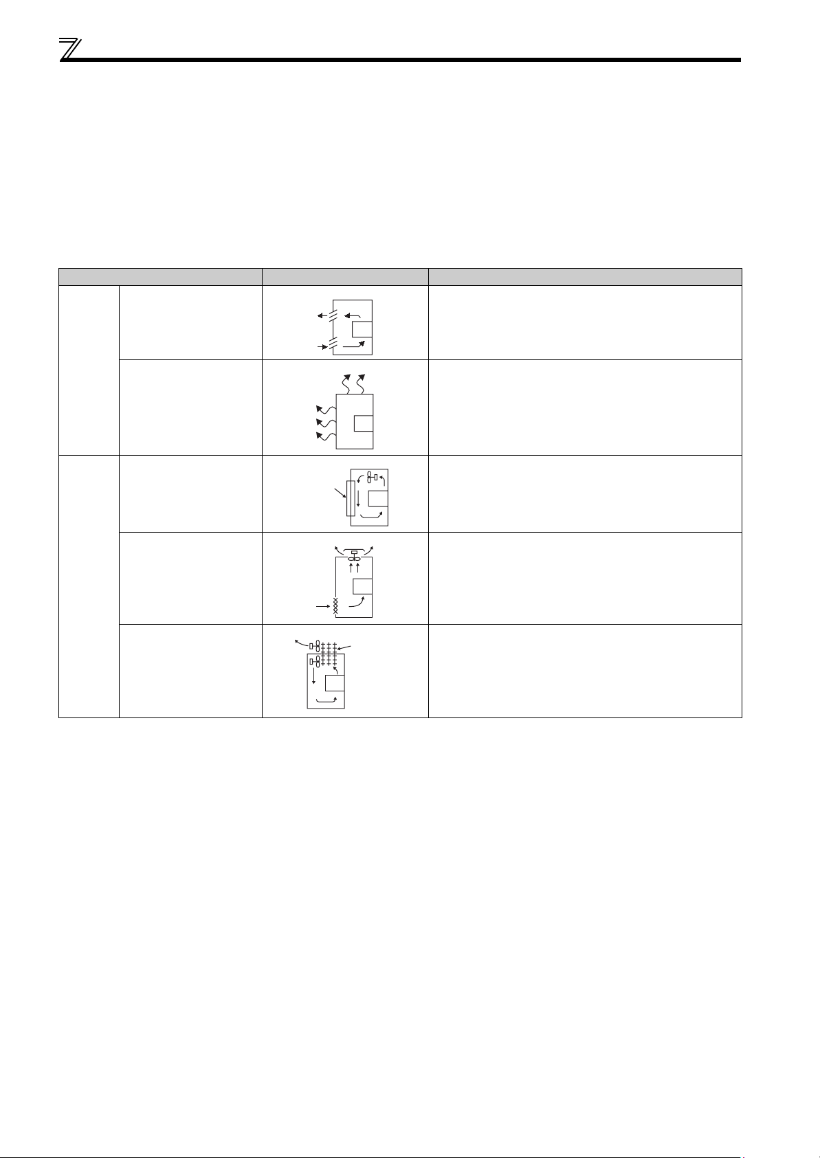
1.4.2 Cooling system types for inverter enclosure
From the enclosure that contains the inverter, the heat of the inverter and other equipment (transformers, lamps, resistors,
etc.) and the incoming heat such as direct sunlight must be dissipated to keep the in-panel temperature lower than the
permissible temperatures of the in-panel equipment including the inverter.
The cooling systems are classified as follows in terms of the cooling calculation method.
1) Cooling by natural heat dissipation from the enclosure surface (totally enclosed type)
2) Cooling by heat sink (aluminum fin, etc.)
3) Cooling by ventilation (forced ventilation type, pipe ventilation type)
4) Cooling by heat exchanger or cooler (heat pipe, cooler, etc.)
Cooling System Enclosure Structure Comment
Natural
cooling
Forced
cooling
Natural ventilation
(enclosed, open type)
Natural ventilation
(totally enclosed type)
Fin cooling
Forced ventilation
Heat pipe Totally enclosed type for panel downsizing.
Heatsink
INV
INV
INV
INV
Heat pipe
INV
Low in cost and generally used, but the panel size increases
as the inverter capacity increases. For relatively small
capacities.
Being a totally enclosed type, the most appropriate for hostile
environment having dust, dirt, oil mist, etc. The panel size
increases depending on the inverter capacity.
Having restrictions on the heatsink mounting position and
area, and designed for relative small capacities.
For general indoor installation. Appropriate for panel
downsizing and cost reduction, and often used.
10
Page 22
Installation of the inverter and enclosure design
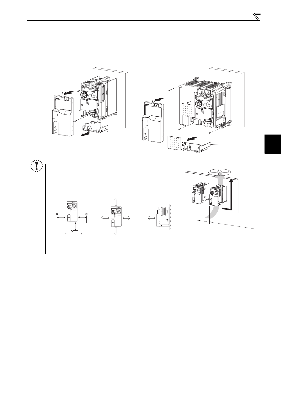
1.4.3 Inverter placement
(1) Installation of the inverter
Enclosure surface mounting
Remove the front cover and wiring cover to fix the inverter to the surface.
FR-E720-0.1KNF to 0.75KNF FR-E720-1.5KNF or higher
FR-E740-0.4KNF or higher
Front cover
Front cover
Wiring cover
Wiring cover
Note
When encasing multiple inverters, install them in parallel as a cooling
measure.
Install the inverter vertically.
For heat dissipation and maintenance, take at least the clearances
shown in the table below from the inverter to the other devices and to
the enclosure surface.
Measurement
position
5cm
Measurement
position
-10 C to +50 C (non-freezing)
∗1 Take 5cm or more clearances for 5.5K or higher.
∗2 When using the inverters at the surrounding air temperature of 40°C or less, the inverters can be installed without any clearance between
them (0cm clearance).
5cm
5cm
1cm or
∗1, ∗2
more
10cm or more
1cm or
∗1, ∗2
more
10cm or more
1cm or
more
∗1
Refer to the clearances
on the left.
Vertical
(2) Above inverter
Heat is blown up from inside the inverter by the small fan built in the unit. Any equipment placed above the inverter should be
heat resistant.
1
OUTLINE
11
Page 23
Installation of the inverter and enclosure design
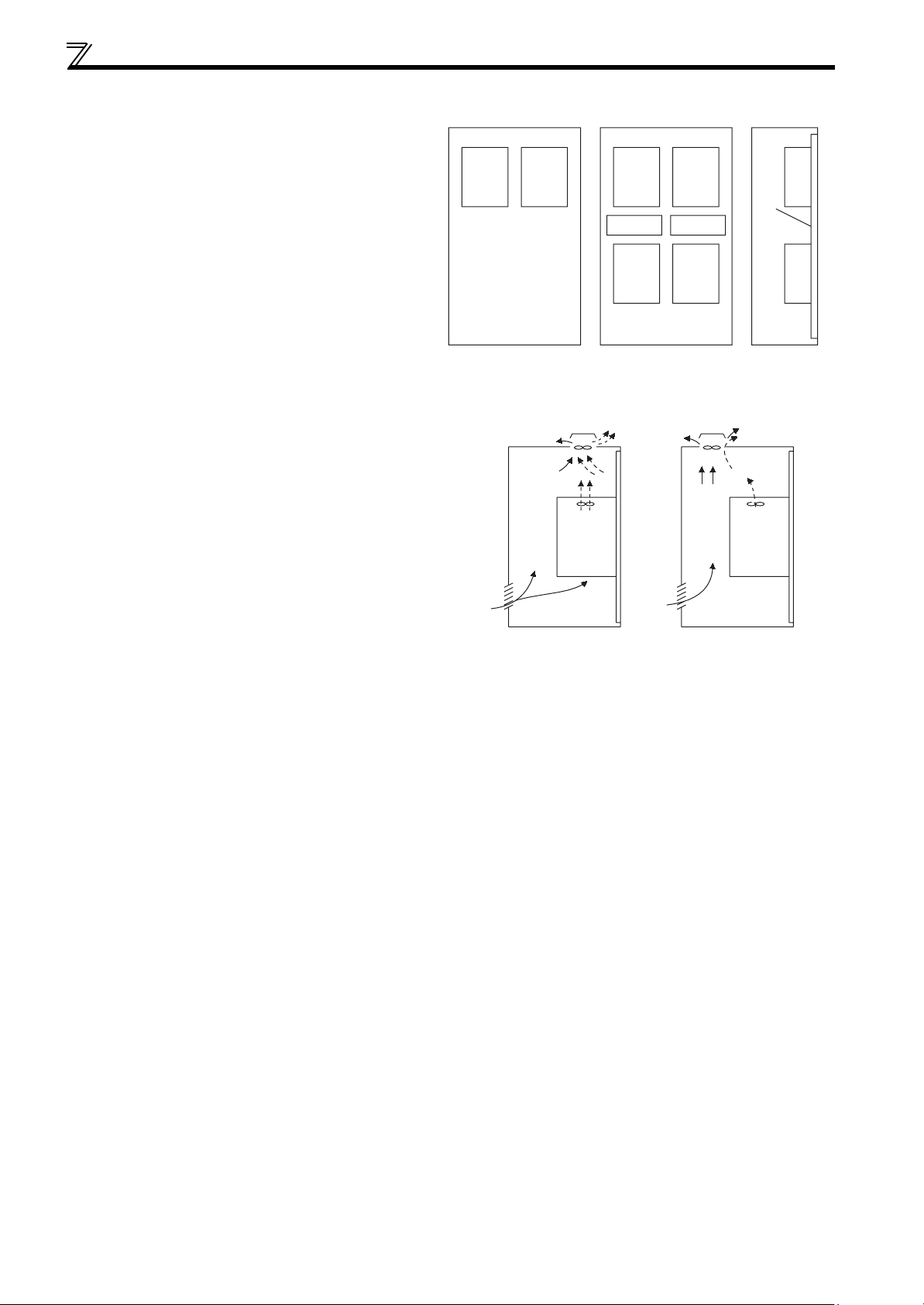
(3) Arrangement of multiple inverters
When multiple inverters are placed in the same
enclosure, generally arrange them horizontally as shown
in the right figure (a). When it is inevitable to arrange
them vertically to minimize space, take such measures as
to provide guides since heat from the bottom inverters
can increase the temperatures in the top inverters,
causing inverter failures.
When mounting multiple inverters, fully take caution not
to make the surrounding air temperature of the inverter
higher than the permissible value by providing ventilation
and increasing the panel size.
(4) Arrangement of ventilation fan and inverter
Heat generated in the inverter is blown up from the bottom of
the unit as warm air by the cooling fan. When installing a
ventilation fan for that heat, determine the place of ventilation
fan installation after fully considering an air flow. (Air passes
through areas of low resistance. Make an airway and airflow
plates to expose the inverter to cool air.)
(a) Horizontal arrangement
InverterInverter
Enclosure Enclosure
Arrangement of multiple inverters
Inverter Inverter
Inverter
Guide Guide
Inverter
Inverter
Inverter
(b) Vertical arrangement
Guide
<Good example> <Bad example>
Placement of ventilation fan and inverter
12
Page 24

2 WIRING
This chapter describes the basic "WIRING" for use of this
product.
Always read the instructions before using the equipment.
1
2.1 Wiring............................................................................................. 14
2.2 Main circuit terminal specifications ............................................ 15
2.3 Control circuit specifications ...................................................... 20
2.4 Connection of stand-alone option unit ....................................... 25
2
3
4
5
6
13
7
8
Page 25
Wiring
2.1 Wiring
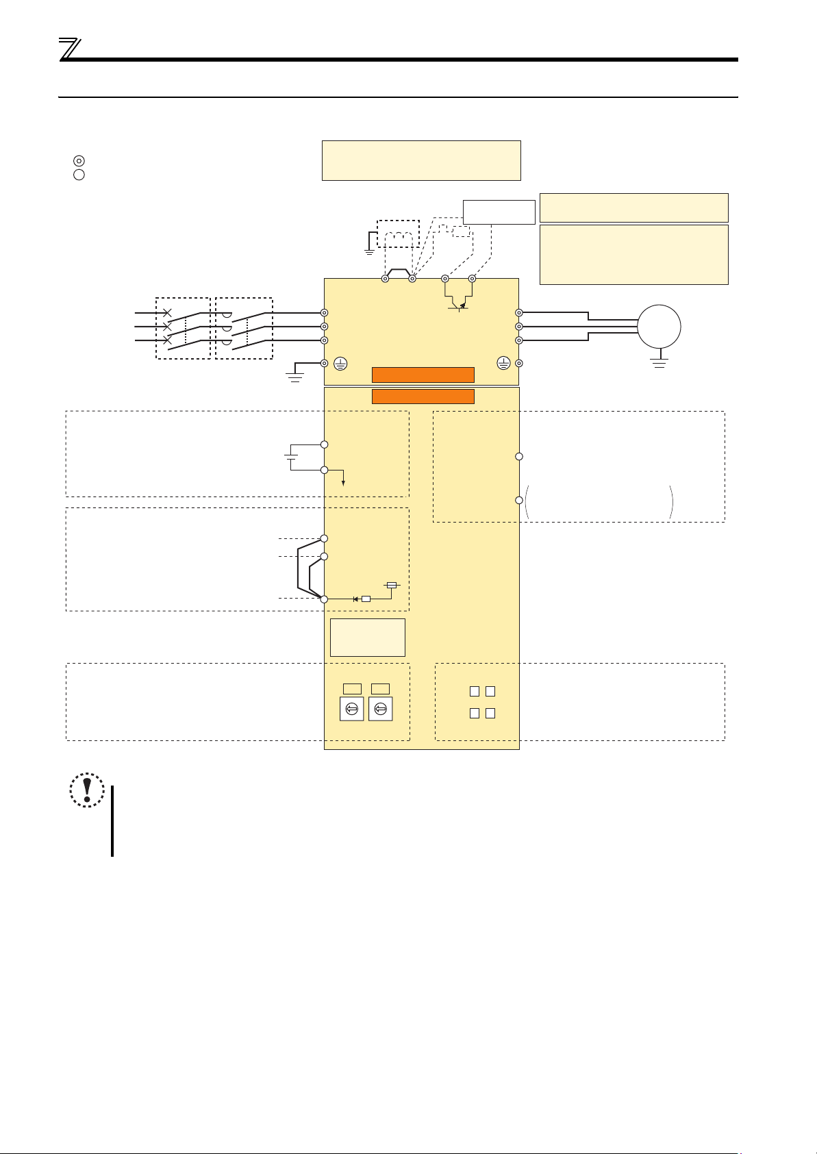
2.1.1 Terminal connection diagram
Sink logic
Main circuit terminal
Control circuit terminal
MCCB MC
Three-phase
AC power
supply
24V external power supply
Safety stop signal
Safety stop input (Channel 1)
Safety stop input (Channel 2)
Safety stop input common
Earth
(Ground)
24V power supply
Common terminal
Shorting
wire
*1. DC reactor (FR-HEL)
When connecting a DC reactor, remove the
jumper across P1 and P/+.
Earth
(Ground)
Jumper
R/L1
S/L2
T/L3
*1
P1 P/+
Inrush current
limit circuit
R
*3
PR
*2
Main circuit
Control circuit
+24
SD
S1
Output
shutoff
S2
circuit
24V
PC
N/-
Brake unit
(Option)
Y0
SE
*2 A brake transistor is not built-in to the 0.1K
and 0.2K.
*3 Brake resistor (FR-ABR, MRS, MYS type)
Install a thermal relay to prevent an
overheat and burnout of the brake resistor.
(The brake resistor cannot be connected
to the 0.1K and 0.2K.)
U
V
W
Open collector output
Open collector output Y0
(Safety monitor output 2)
Open collector output common
Sink/source common
Motor
IM
Earth (Ground)
Node address setting
NOTE
To prevent a malfunction caused by noise, separate the signal cables more than 10cm from the power cables. Also
separate the main circuit wire of the input side and the output side.
After wiring, wire offcuts must not be left in the inverter.
Wire offcuts can cause an alarm, failure or malfunction. Always keep the inverter clean. When drilling mounting holes
in an enclosure etc., take care not to allow chips and other foreign matter to enter the inverter.
FL remote
communication
connector
X1
X10
3
3
2
2
4
4
1
1
5
0
5
0
6
6
9
9
7
7
8
8
D1 D2
D3 D4
LED (operation status display)
Communication setting status LED (CHG)
D1:
D2: Device status LED (DEV)
D3: Reception/transmission LED (TX/RX)
D4: Remote status LED (RMT)
14
Page 26
Main circuit terminal specifications
r
2.2 Main circuit terminal specifications
2.2.1 Specification of main circuit terminal
Terminal
Symbol
R/L1,
S/L2,
T/L3
U, V, W Inverter output Connect a three-phase squirrel-cage motor.
P/+, PR Brake resistor connection
P/+, N/- Brake unit connection Connect the brake unit (FR-BU2).
P/+, P1 DC reactor connection Remove the jumper across terminals P/+ and P1 and connect a DC reactor.
AC power input Connect to the commercial power supply.
Earth (Ground) For earthing (grounding) the inverter chassis. Must be earthed (grounded).
Terminal Name Description
Connect a brake resistor (FR-ABR, MRS type, MYS type) across terminals P/+ and
PR.
(The brake resistor cannot be connected to the 0.1K or 0.2K.)
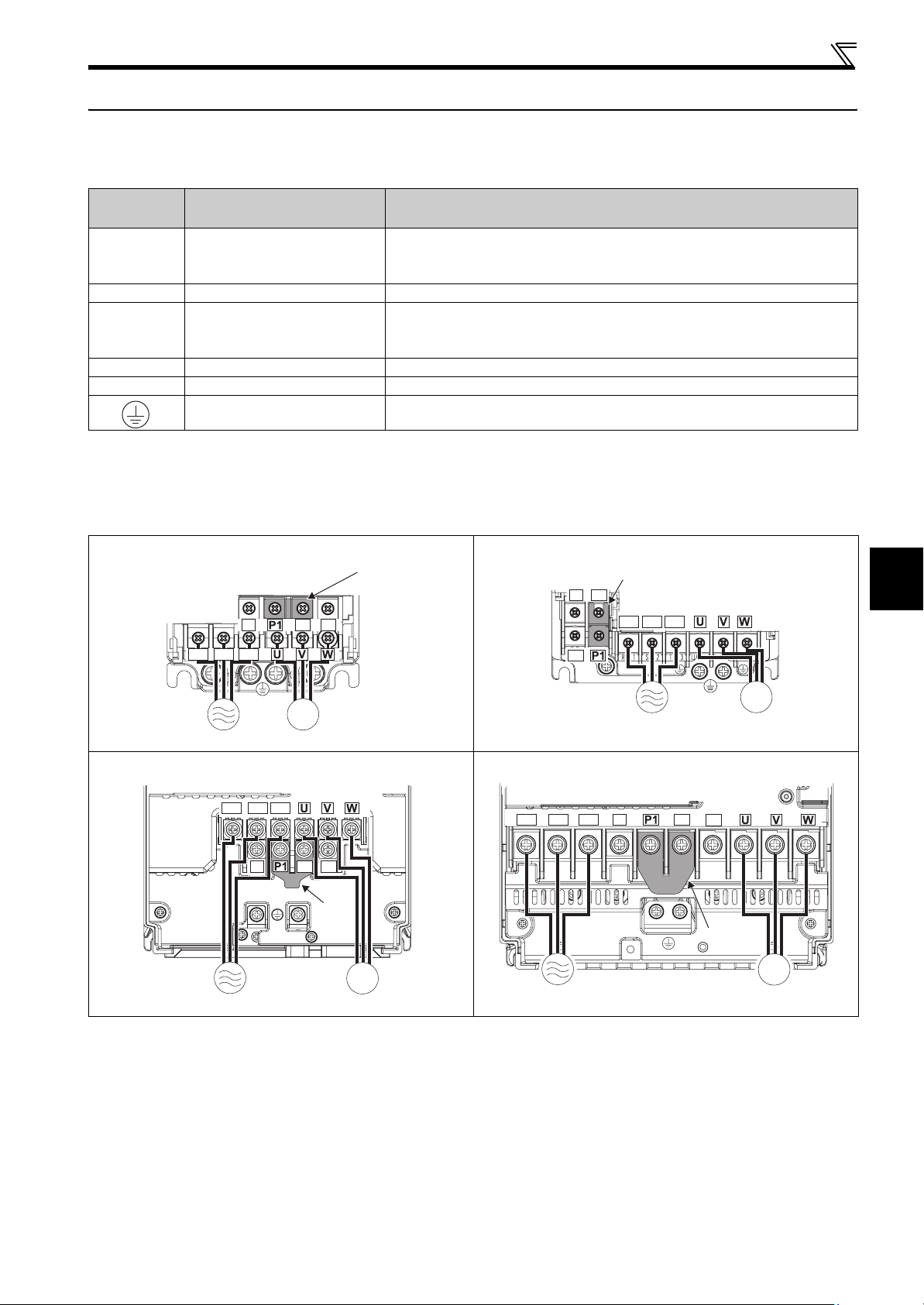
2.2.2 Terminal arrangement of the main circuit terminal, power supply and the motor wiring
Three-phase 200V class
FR-E720-0.1KNF to 0.75KNF FR-E720-1.5KNF to 3.7KNF
N/-
Jumpe
N/-
P/+ PR
Jumper
P/+
R/L1 S/L2 T/L3
2
R/L1 S/L2 T/L3
PR
IM
MotorPower supply
FR-E720-5.5KNF, 7.5KNF FR-E720-11KNF, 15KNF
R/L1 S/L2 T/L3
N/-
P/+
PR
Jumper
R/L1 S/L2 T/L3
IM
Power supply
Motor
Power supply
N/-
P/+
PR
Jumper
IM
Motor
MotorPower supply
WIRING
IM
15
Page 27
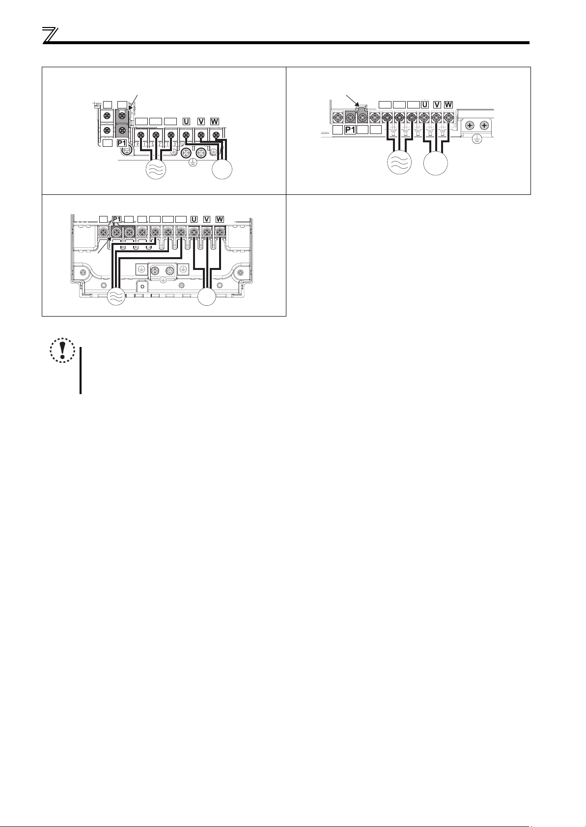
Main circuit terminal specifications
Three-phase 400V class
FR-E740-0.4KNF to 3.7KNF FR-E740-5.5KNF, 7.5KNF
N/-
P/+
PR
FR-E740-11KNF, 15KNF
N/-
Jumper
Power supply
NOTE
Make sure the power cables are connected to the R/L1, S/L2, T/L3. (Phase need not be matched.) Never connect the
power cable to the U, V, W of the inverter. Doing so will damage the inverter.
Connect the motor to U, V, W. Turning ON the forward rotation switch (signal) at this time rotates the motor
counterclockwise when viewed from the load shaft.
Jumper
R/L1 S/L2 T/L3
R/L1 S/L2 T/L3
P/+
PR
IM
Motor
IM
MotorPower supply
Jumper
N/-
P/+
R/L1 S/L2 T/L3
PR
IM
MotorPower supply
16
Page 28
Main circuit terminal specifications
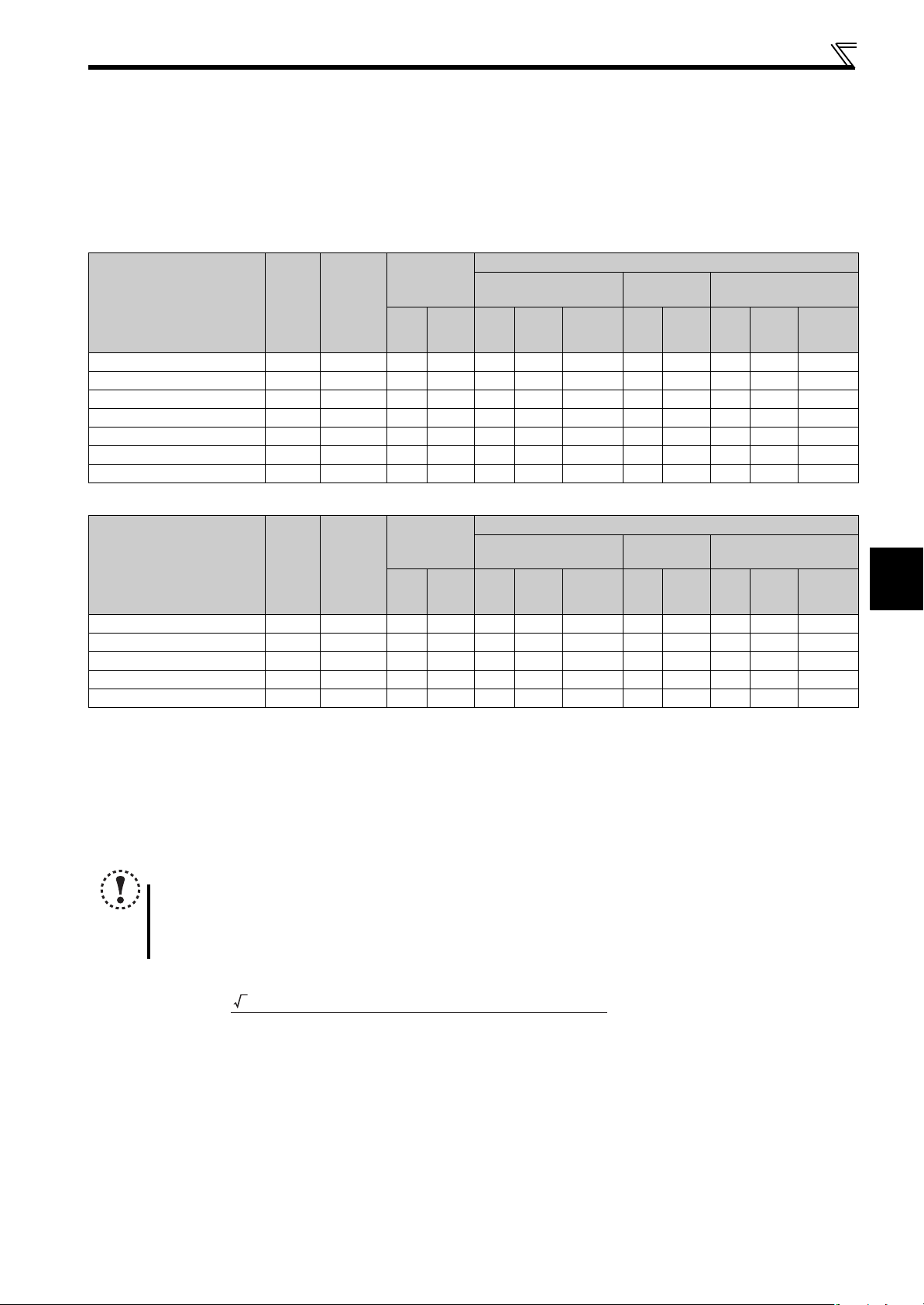
2.2.3 Cables and wiring length
(1) Applicable cable size
Select the recommended cable size to ensure that a voltage drop will be 2% or less.
If the wiring distance is long between the inverter and motor, a main circuit cable voltage drop will cause the motor torque to
decrease especially at the output of a low frequency.
The following table indicates a selection example for the wiring length of 20m.
Three-phase 200V class (when input power supply is 220V)
Crimping
Applicable Inverter
Model
Termin al
Screw
Size ∗4
Tightening
Torque
·
m
N
Terminal
R/L1
S/L2
U, V, W
T/L3
FR-E720-0.1KNF to 0.75KNF M3.5 1.2 2-3.5 2-3.5 2 2 2 14 14 2.5 2.5 2.5
FR-E720-1.5KNF, 2.2KNF M4 1.5 2-4 2-4 2 2 2 14 14 2.5 2.5 2.5
FR-E720-3.7KNF M4 1.5 5.5-4 5.5-4 3.5 3.5 3.5 12 12 4 4 4
FR-E720-5.5KNF M5 2.5 5.5-5 5.5-5 5.5 5.5 5.5 10 10 6 6 6
FR-E720-7.5KNF M5 2.5 14-5 8-5 14 8 5.5 6 8 16 10 6
FR-E720-11KNF M5 2.5 14-5 14-5 14 14 14 6 6 16 16 16
FR-E720-15KNF M6(M5) 4.4 22-6 22-6 22 22 14 4 4 25 25 16
HIV Cables, etc. (mm2)
∗1
R/L1
S/L2
T/L3
U, V, W
Earthing
cable
Cable Size
AWG ∗2
R/L1
S/L2
U, V, W
T/L3
PVC Cables, etc. (mm2)
∗3
R/L1
S/L2
T/L3
U, V, W
Earthing
cable
Three-phase 400V class (when input power supply is 440V)
Crimping
Applicable Inverter
Model
Termin al
Screw
Size ∗4
Tightening
Torque
·
m
N
Terminal
R/L1
S/L2
U, V, W
T/L3
FR-E740-0.4KNF to 3.7KNF M4 1.5 2-4 2-4 2 2 2 14 14 2.5 2.5 2.5
FR-E740-5.5KNF M4 1.5 5.5-4 2-4 3.5 2 3.5 12 14 4 2.5 4
FR-E740-7.5KNF M4 1.5 5.5-4 5.5-4 3.5 3.5 3.5 12 12 4 4 4
FR-E740-11KNF M4 1.5 5.5-4 5.5-4 5.5 5.5 8 10 10 6 6 10
FR-E740-15KNF M5 2.5 8-5 8-5 8 8 8 8 8 10 10 10
∗1
The cable size is that of the cable (HIV cable (600V class 2 vinyl-insulated cable) etc.) with continuous maximum permissible temperature of 75°C. Assumes
that the surrounding air temperature is 50°C or less and the wiring distance is 20m or less.
∗2
The recommended cable size is that of the cable (THHW cable) with continuous maximum permissible temperature of 75°C. Assumes that the surrounding air
temperature is 40°C or less and the wiring distance is 20m or less. (Selection example for use mainly in the United States.)
∗3
The recommended cable size is that of the cable (PVC cable) with continuous maximum permissible temperature of 70°C. Assumes that the surrounding air
temperature is 40°C or less and the wiring distance is 20m or less. (Selection example for use mainly in Europe.)
∗4
The terminal screw size indicates the terminal size for R/L1, S/L2, T/L3, U, V, W, and a screw for earthing (grounding).
A screw for earthing (grounding) of the FR-E720-15KNF is indicated in ( ).R/L1, S/L2P/N/
HIV Cables, etc. (mm2)
∗1
R/L1
S/L2
T/L3
U, V, W
Earthing
cable
Cable Size
AWG ∗2
R/L1
U, V, W
S/L2
T/L3
PVC Cables, etc. (mm2)
∗3
R/L1
S/L2
T/L3
U, V, W
Earthing
cable
NOTE
Tighten the terminal screw to the specified torque. A screw that has been tighten too loosely can cause a short circuit
or malfunction. A screw that has been tighten too tightly can cause a short circuit or malfunction due to the unit
breakage.
Use crimping terminals with insulation sleeve to wire the power supply and motor.
2
WIRING
The line voltage drop can be calculated by the following formula:
Line voltage drop [V]=
3 × wire resistance[mΩ/m] × wiring distance[m] × current[A]
1000
Use a larger diameter cable when the wiring distance is long or when it is desired to decrease the voltage drop (torque
reduction) in the low speed range.
17
Page 29
Main circuit terminal specifications
(2) Earthing (Grounding) precautions
Always earth (ground) the motor and inverter.
1) Purpose of earthing (grounding)
Generally, an electrical apparatus has an earth (ground) terminal, which must be connected to the ground before use.
An electrical circuit is usually insulated by an insulating material and encased. However, it is impossible to manufacture
an insulating material that can shut off a leakage current completely, and actually, a slight current flow into the case.
The purpose of earthing (grounding) the case of an electrical apparatus is to prevent operator from getting an electric
shock from this leakage current when touching it.
To avoid the influence of external noises, this earthing (grounding) is important to audio equipment, sensors, computers
and other apparatuses that handle low-level signals or operate very fast.
2) Earthing (grounding) methods and earthing (grounding) work
As described previously, earthing (grounding) is roughly classified into an electrical shock prevention type and a noise-
affected malfunction prevention type. Therefore, these two types should be discriminated clearly, and the following
work must be done to prevent the leakage current having the inverter's high frequency components from entering the
malfunction prevention type earthing (grounding):
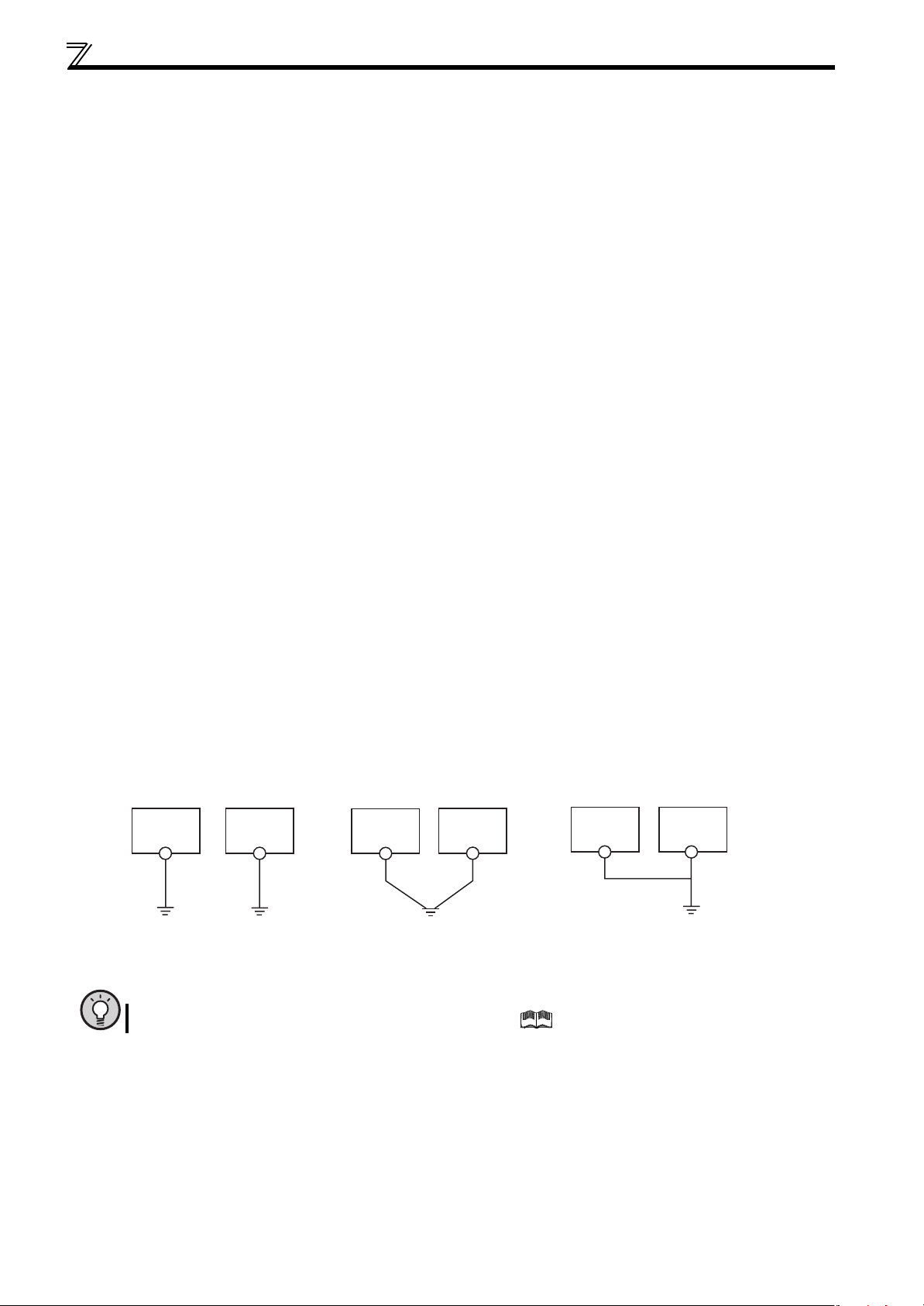
(a)If possible, use (l) independent earthing (grounding) in figure below for the inverter. If independent earthing
(grounding) is not available, use (ll) joint earthing (grounding) in the figure below which the inverter is connected with
the other equipment at an earthing (grounding) point. The (lll) common earthing (grounding) as in the figure below,
which inverter shares a common earth (ground) cable with the other equipment, must be avoided.
A leakage current including many high frequency components flows in the earth (ground) cables of the inverter and
inverter-driven motor. Therefore, use the independent earthing (grounding) and separated the earthing (grounding)
cable of the inverter from equipments sensitive to EMI.
In a high building, it may be effective to use the EMI prevention type earthing (grounding) connecting to an iron
structure frame, and electric shock prevention type earthing (grounding) with the independent earthing (grounding)
together.
(b)This inverter must be earthed (grounded). Earthing (Grounding) must conform to the requirements of national and
local safety regulations and electrical codes. (NEC section 250, IEC 536 class 1 and other applicable standards).
Use an neutral-point earthed (grounded) power supply for 400V class inverter in compliance with EN standard.
(c)Use the thickest possible earth (ground) cable. The earth (ground) cable should be of not less than the size indicated
in the table on the previous page 17.
(d)The grounding point should be as near as possible to the inverter, and the ground wire length should be as short as
possible.
(e)Run the earth (ground) cable as far away as possible from the I/O wiring of equipment sensitive to noises and run
them in parallel in the minimum distance.
18
Inverter
(I)Independent earthing.......Best
Other
equipment
Inverter
(II)Common earthing.......Good
Other
equipment
Inverter
(III)Common earthing.......Not allowed
Other
equipment
POINT
To be compliant with the EU Directive (Low Voltage Directive), refer to the Instruction Manual (Basic).
Page 30
Main circuit terminal specifications
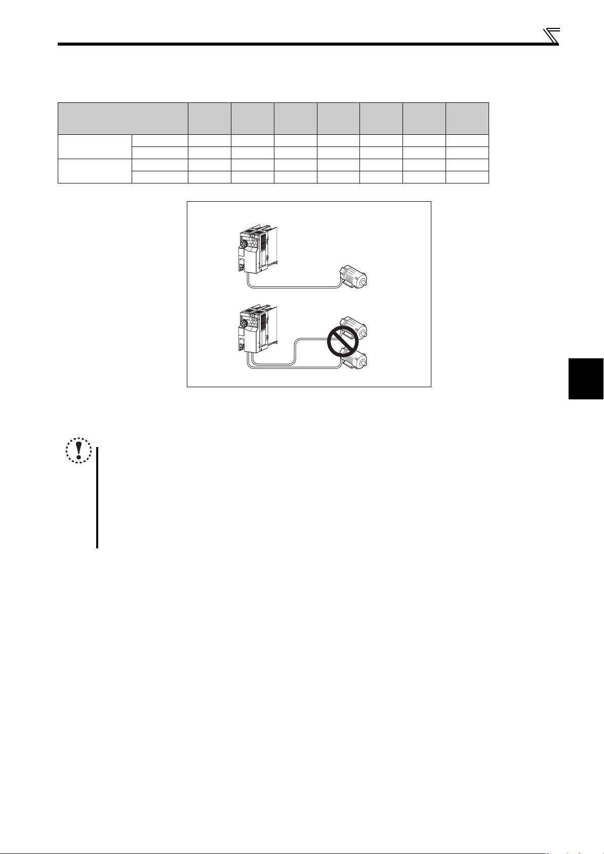
(3) Total wiring length
The overall wiring length for connection of a single motor or multiple motors should be within the value in the table
below.
Pr. 72 PWM frequency selection
1 (1kHz) or less
(2kHz to 14.5kHz)
Setting
(carrier frequency)
200V class 200m 200m 300m 500m 500m 500m 500m
400V class - - 200m 200m 300m 500m 500m
2 to15
200V class 30m 100m 200m 300m 500m 500m 500m
400V class - - 30m 100m 200m 300m 500m
0.1K 0.2K 0.4K 0.75K 1.5K 2.2K
Total wiring length (3.7K or higher)
500m or less
300m
300m
300m+300m=600m
3.7K
or Higher
When driving a 400V class motor by the inverter, surge voltages attributable to the wiring constants may occur at the motor
terminals, deteriorating the insulation of the motor. In this case, refer to page 39.
2
NOTE
Especially for long-distance wiring, the inverter may be affected by a charging current caused by the stray
capacitances of the wiring, leading to a malfunction of the overcurrent protective function, fast response current limit
function, or stall prevention function or a malfunction or fault of the equipment connected on the inverter output side.
If malfunction of fast-response current limit function occurs, disable this function. If malfunction of stall prevention
function occurs, increase the stall level. (Refer to page 101 for Pr. 22 Stall prevention operation level and Pr. 156 Stall prevention
operation selection )
Refer to page 163 for details of Pr. 72 PWM frequency selection.
When using the automatic restart after instantaneous power failure function with wiring length exceeding 100m,
select without frequency search (Pr. 162 = "1 (initial value), 11"). (Refer to page 151)
WIRING
19
Page 31

Control circuit specifications
2.3 Control circuit specifications
2.3.1 Control circuit terminal
(1) Input signal
Ter mi nal
Typ e
Symbol
+24
Terminal Name Description Rated Specifications
24V external power
supply
Even when the main circuit power supply is OFF, FL
remote communication continues with the input from
the 24V external power supply.
Input voltage
23.5 to 26.5VDC
Input current
0.7A or less
Refer to
Page
23
SD
24V external power supply
S1
S2
Safety stop
PC
24V external power
supply common terminal
Safety stop input
(Channel 1)
Safety stop input
(Channel 2)
Safety stop input terminal
common
(2) Output signal
Ter mi nal
Typ e
Symbol
Y0
Open collector
SE
Terminal Name Description Rated Specifications
Open collector output Y0
(safety monitor output 2)
Open collector output
common
Common terminal for the terminal +24 — —
Terminal S1/S2 are safety stop signals for use with in
conjunction with an approved external safety unit.
Both terminal S1/S2 must be used in dual channel
form. Inverter output is shutoff depending on shorting/
opening between S1 and PC, S2 and PC.
In the initial status, terminal S1 and S2 are shorted
with terminal PC by shorting wire.
Remove the shorting wire and connect the safety
relay module when using the safety stop function.
Common terminal for safety stop input terminals S1
and S2.
Input resistance 4.7kΩ
Voltage when contacts are
open
21 to 26VDC
When contacts are short-
circuited
4 to 6mADC
——
24
Refer to
Page
This terminal is switched to Low during the operation
with no internal safety circuit fault (E.SAF, E.6, E.7,
E.CPU). It is switched to High in operation statuses
other than above.
(Low indicates that the open collector output transistor
is ON (conducts). High indicates that the transistor is
OFF (does not conduct).)
Common terminal of terminal Y0. — —
Permissible load 24VDC
(maximum 27VDC) 0.1A
(a voltage drop is 3.4V
maximum when the signal
is ON)
24
(3) Communication
Connector Name Description
FL remote communication
connector
With the FL remote communication connector, FL remote communication can be performed. 48
20
Refer to
Page
Page 32

Control circuit specifications
2.3.2 Wiring of control circuit
(1) Terminal layout of control circuit terminals
Recommend wire size:
2
0.3mm
to 0.75mm
(2) Wiring method
zWiring
For the control circuit wiring, strip off the sheath of wires, and use them with a blade terminal. For a single wire, strip off the
sheath of the wire and apply directly.
Insert the blade terminal or the single wire into a socket of the terminal.
1) Strip off the sheath about the length below. If the length of the sheath peeled is too long, a short circuit may occur
among neighboring wires. If the length is too short, wires might come off.
Wire the stripped wire after twisting it to prevent it from becoming loose. In addition, do not solder it.
2
S1 S2+24 SD PC Y0 SE
Wire stripping length
10mm
2) Crimp the blade terminal.
Insert wires to a blade terminal, and check that the wires come out for about 0 to 0.5 mm from a sleeve.
Check the condition of the blade terminal after crimping. Do not use a blade terminal of which the crimping is
inappropriate, or the face is damaged.
Unstranded
Wire
Shell
Sleeve
0 to 0.5mm
Damaged
Crumpled tip
Blade terminals available on the market: (as of Oct. 2008)
zPhoenix Contact Co.,Ltd.
Wire Size (mm2)
0.3 AI 0,5-10WH — —
0.5 AI 0,5-10WH — AI 0,5-10WH-GB
0.75 AI 0,75-10GY A 0,75-10 AI 0,75-10GY-GB
1 AI 1-10RD A1-10 AI 1-10RD/1000GB
1.25, 1.5 AI 1,5-10BK A1,5-10 —
0.75 (for two wires) AI-TWIN 2 x 0,75-10GY — —
∗A blade terminal with an insulation sleeve compatible with MTW wire which has a thick wire insulation
with insulation sleeve without insulation sleeve for UL wire∗
Blade Terminal Model
zNICHIFU Co.,Ltd.
Wire Size (mm2)
0.3 to 0.75 BT 0.75-11 VC 0.75 NH 67
Blade terminal product
number
Insulation product number
2
WIRING
wires
Wires are not inserted
into the shell
Blade terminal
crimping tool
CRIMPFOX ZA3
Blade terminal
crimping tool
21
Page 33

Control circuit specifications
3) Insert the wire into a socket.
When using a single wire or a stranded wire without a blade terminal, push an open/close button all the way down
with a flathead screw driver, and insert the wire.
Open/close button
Flathead screwdriver
NOTE
When using a stranded wire without a blade terminal, twist enough to avoid short circuit with a nearby terminals or
wires.
Place the flathead screwdriver vertical to the open/close button. In case the blade tip slips, it may cause to damage of
inverter or injury.
zWire removal
Pull the wire with pushing the open/close button all the way down firmly with a flathead screwdriver.
Open/close button
Flathead screwdriver
NOTE
Use a small flathead screwdriver (Tip thickness: 0.4mm/tip width: 2.5mm).
If a flathead screwdriver with a narrow tip is used, terminal block may be damaged.
Introduced products :(as of Oct. 2008)
Product Type Maker
Flathead screwdriver SZF 0- 0,4 x 2,5 Phoenix Contact Co.,Ltd.
Place the flathead screwdriver vertical to the open/close button. In case the blade tip slips, it may cause to damage of
inverter or injury.
(3) Control circuit common terminals (SD, SE)
Terminals SD and SE are common terminals for I/O signals. (Both common terminals are isolated from each other.) Do not
earth them.
Terminal SD is a common terminal for 24V external power supply terminal (+24). The open collector circuit is isolated from the
internal control circuit by photocoupler.
Terminal SE is a common terminal for the open collector output terminal (Y0). The contact input circuit is isolated from the
internal control circuit by photocoupler.
(4) Wiring instructions
1) It is recommended to use the cables of 0.3mm2 to 0.75mm2 gauge for connection to the control circuit terminals.
2) The maximum wiring length should be 30m.
3) Do not short across terminals +24 and SD. It may cause a failure to the external power supply.
4) Use shielded or twisted cables for connection to the control circuit terminals and run them away from the main and power
circuits (including the 200V relay sequence circuit).
22
Page 34

Control circuit specifications
2.3.3 Connecting the 24V external power supply
FL remote communication between the master module and the inverter can be continued while the main power circuit is OFF
if the 24V external power supply is connected across terminals +24 and SD. When the main circuit power supply is turned ON,
the power supply changes from the 24V external power supply to the main circuit power supply.
(1) Specification of the applied 24V external power supply
Input voltage 23.5 to 26.5VDC
Input current 0.7A or less
(2) Operation panel display during the 24V external power supply operation
"EV" flickers.
Flickering
(3) Function of the 24V external power supply operation
When the main power supply is turned ON during the 24V external power supply operation, a reset is performed in the
inverter, then the power supply changes to the main circuit power supply. During the reset operation in the inverter, the
inverter cannot be controlled through the FL remote communication.
The operation stops when the power supply changes to the 24V external power supply from the main circuit power
supply regardless of the operating status (in a stop, in running, in automatic restart after instantaneous power failure,
in offline (online) tuning, in main circuit capacitor life measurement).
2
All start signals (STF signal, STR signal, and on the operation panel) are invalid during the 24V external power
supply operation.
Faults history and parameters can be read and parameters can be written (when the parameter write from the
operation panel is enabled) using the operation panel keys.
The safety stop function is also valid during the 24V external power supply operation. When the safety stop function is
active, however, "SA" is not displayed because "EV" is displayed. The "EV" display has priority over the "SA" display.
The following items can be monitored during the 24V external power supply operation.
Frequency setting, output current peak value
actual operation time
∗ The monitored data is not updated after the power supply is changed from the main circuit power supply.
∗
, cumulative power∗, and cumulative power 2∗ (monitor dedicated to the FL remote communication)
∗
, converter output voltage peak value∗, cumulative energization time,
(Refer to page 147 for the details of each monitor.)
The valid signals when the 24V external power supply is ON are ALM, Safety alarm, Edit, NET, READY and Y95.
(Other signals are OFF.)
(Refer to page 59 and 60 for the detail of each signal.)
The alarms, which have occurred when the main circuit power supply is ON, continue to be output after the power
supply is changed to the 24V external power supply. Perform the inverter reset to reset the alarms.
The retry function is invalid for all alarms when the 24V external power supply is ON.
If the power supply changes from the main circuit power supply to the 24V external power supply while measuring the
main circuit capacitor's life in the PU operation mode, the measurement completes after the power supply changes
back to the main circuit power supply (Pr.259 = "3").
NOTE
When the 24V external power supply is input while the main circuit power supply is OFF, the FL remote
communication is enabled, but the inverter operation is disabled.
Inrush current higher than the value described in (1) may flow at a power-ON. Confirm that the power supply and
other devices are not affected by the inrush current and the voltage drop caused by it.
When the wiring length between the external power supply and the inverter is long, the voltage often drops. Select the
appropriate wiring size and length to keep the voltage in the rated input voltage range.
In a serial connection of several inverters, the current increases when it flows through the inverter wiring near the
power supply. The increase of the current causes voltage to drop further. When connecting different inverters to
different power supplies, use the inverters after confirming that the input voltage of each inverter is within the rated
input voltage range.
"E.SAF" may appear when the start-up time of the 24V power supply is too long in the 24V external power supply
operation.
WIRING
23
Page 35

Control circuit specifications
2.3.4 Safety stop function
(1) Description of the function
The terminals related to the safety stop function are shown below.
Terminal Symbol Description
S1∗1 For input of safety stop channel 1.
S2
∗1 For input of safety stop channel 2.
PC
∗1 Common terminal for terminal S1 and S2.
Y0 (SAFE2 signal)
Outputs when an alarm or failure is detected.
The signal is output when no internal safety circuit failure
∗2 exists.
SE Common terminal for open collector outputs (terminal Y0)
∗1 In the initial status, terminal S1 and S2 are shorted with terminal PC by shortening wire. Remove the shortening wire and connect the safety relay module
when using the safety stop function.
∗2 At an internal safety circuit failure, one of E.SAF, E.6, E.7, and E.CPU is displayed on the operation panel.
......Specifications differ according to the date assembled. Refer to page 232 to check the SERIAL number.
NOTE
y
Hold the ON or OFF status for 2ms or longer to input signal to terminal S1 or S2. Signal input shorter than 2ms is not recognized.
y SAFE2 signal can only be used to output an alarm or to prevent restart of an inverter. The signal cannot be used as
safety stop input signal to other devices.
(2) Wiring connection diagram
Between S1 and PC / S2 and PC
Open: In safety stop state.
Short: Other than safety stop state.
OFF: Internal safety circuit failure.
∗2
ON : No internal safety circuit failure.∗2
To prevent restart at fault occurrence, connect terminals Y0 (SAFE2 signal) and SE to terminals XS0 and XS1, which are
the feedback input terminals of the safety relay module. Terminal Y0 is turned OFF at a fault occurrence.
R S T
U V W
IM
DC24V
START/RESET
Emergency
stop button
COM0
X0 X1
+24V
24G
MITSUBISHI MELSEC Safety relay module
QS90SR2SN-Q
Internal
Safety
Circuit
COM1
XS0
XS1
K1
K2
Z00
Z10
Z20
Z11 Z01 Z21
Y0(SAFE2)
SE
PC
S1
S2
Inverter
I/O control
Output shutoff
circuit
(3) Safety stop function operation
Input power
Input signal
S1-PC S2-PC
Internal safety
circuit∗1
Output signal (SAFE2)∗3 Operation state
O FF ----- ----- ----- O F F O u t p u t s h u t o ff ( S a f e s t a te )
No failure ON Drive enabled
Detected OFF Output shutoff (Safe state)
No failure∗2 ON Output shutoff (Safe state)
Detected OFF Output shutoff (Safe state)
ON
Short Short
Open Open
Short Open Detected OFF Output shutoff (Safe state)
Open
∗1 At an internal safety circuit failure, one of E.SAF, E.6, E.7, and E.CPU is displayed on the operation panel.
∗2 SA is displayed when both of the S1 and S2 signals are in open status and no internal safety circuit failure exists.
∗3 ON: Transistor used for an open collector output is conducted.
OFF: Transistor used for an open collector output is not conducted.
Short Detected OFF Output shutoff (Safe state)
For more details, refer to the Safety stop function instruction manual (BCN-A211508-004). (Refer to the front cover of the Instruction
Manual (Basic) for how to obtain the manual.)
24
Page 36

Connection of stand-alone option unit
R
2.4 Connection of stand-alone option unit
The inverter accepts a variety of stand-alone option units as required.
Incorrect connection will cause inverter damage or accident. Connect and operate the option unit carefully in accordance with
the corresponding option unit manual.
2.4.1 Connection of a dedicated external brake resistor (MRS type, MYS type, FR-ABR)
Install a dedicated brake resistor (MRS type, MYS type, FR-ABR) outside when the motor is made to run by the load, quick
deceleration is required, etc. Connect a dedicated brake resistor (MRS type, MYS type, FR-ABR) to terminal P/+ and PR.
(For the locations of terminal P/+ and PR, refer to the terminal block layout (page 15).)
Set parameters below.
Connected Brake Resistor
MRS type, MYS type 0 (initial value) —
MYS type
(used at 100% torque / 6%ED)
FR-ABR 1
FR-E720-0.4KNF, 0.75KNF
Pr. 30 Regenerative function
selection Setting
16%
Pr. 70 Special regenerative brake duty Setting
7.5K or lower 10%
11K or higher 6%
Refer to page 136
FR-E720-1.5KNF to 3.7KNF
FR-E740-0.4KNF to 3.7KNF
Connect the brake resistor across terminals P/+ and PR. Connect the brake resistor across terminals P/+ and PR.
Jumper
*1
Brake resistor
Jumper
Terminal P/+
*1
Terminal PR
Terminal P/+
Terminal PR
Brake resistor
FR-E720-5.5KNF to 15KNF FR-E740-5.5KNF to 15KNF
Connect the brake resistor across terminals P/+ and PR. Connect the brake resistor across terminals P/+ and PR.
2
WIRING
Terminal P/+
Terminal P
Jumper
*1
Brake resistor
∗1 Do not remove the jumper across terminals P/+ and P1 except when connecting a DC reactor.
∗2 The shape of jumper differs according to capacities.
Brake resistor
Jumper
Terminal P/+
Terminal PR
*1*2
25
Page 37

Connection of stand-alone option unit
r
It is recommended to configure a sequence, which shuts off power in the input side of the inverter by the external thermal
relay as shown below, to prevent overheat and burnout of the brake resistor (MRS type, MYS type) and high duty brake
resistor (FR-ABR) in case the regenerative brake transistor is damaged. (The brake resistor cannot be connected to the
0.1K and 0.2K.)
MC
Power supply
T∗2
F
MC
OFF
ON
OCR
MC
∗3 Refer to the table below for the type number of each capacity of thermal relay and the diagram below for the connection.
(Always install a thermal relay when using a brake resistor whose capacity is 11K or higher)
∗4 When the power supply is 400V class, install a step-down transformer.
Power
Supply
Vol tag e
200V
Power
Supply
Vol tag e
200V
400V
Brake Resistor
MRS120W200 TH-N20CXHZ-0.7A
MRS120W100 TH-N20CXHZ-1.3A
MRS120W60 TH-N20CXHZ-2.1A
MRS120W40 TH-N20CXHZ-3.6A
MYS220W50 (two units in
parallel)
High-duty
Brake Resistor
FR-ABR-0.4K TH-N20CXHZ-0.7A
FR-ABR-0.75K TH-N20CXHZ-1.3A
FR-ABR-2.2K TH-N20CXHZ-2.1A
FR-ABR-3.7K TH-N20CXHZ-3.6A
FR-ABR-5.5K TH-N20CXHZ-5A
FR-ABR-7.5K TH-N20CXHZ-6.6A
FR-ABR-11K TH-N20CXHZ-11A
FR-ABR-15K TH-N20CXHZ-11A
FR-ABR-H0.4K TH-N20CXHZ-0.24A
FR-ABR-H0.75K TH-N20CXHZ-0.35A
FR-ABR-H1.5K TH-N20CXHZ-0.9A
FR-ABR-H2.2K TH-N20CXHZ-1.3A
FR-ABR-H3.7K TH-N20CXHZ-2.1A
FR-ABR-H5.5K TH-N20CXHZ-2.5A
FR-ABR-H7.5K TH-N20CXHZ-3.6A
FR-ABR-H11K TH-N20CXHZ-6.6A
FR-ABR-H15K TH-N20CXHZ-6.6A
Thermal Relay Type
(Mitsubishi product)
TH-N20CXHZ-5A
Thermal Relay Type
(Mitsubishi product)
Contact
Inverter
R/L1
S/L2
T/L3
110VAC 5A,
220VAC 2A(AC11 class)
110VDC 0.5A,
220VDC 0.25A(DC11class)
110VAC 5A,
220VAC 2A(AC11 class)
110VDC 0.5A,
220VDC 0.25A(DC11 class)
Thermal relay
(OCR) (∗1)
P/+
PR
Contact Rating
Contact Rating
High-duty brake
resistor (FR-ABR)
R
1/L1 5/L3
2/T1 6/T3
To the inverter
terminal P/+
TH-N20
To a resisto
26
NOTE
The brake resistor connected should only be the dedicated brake resistor.
Brake resistor cannot be used with the brake unit, etc.
Do not use the brake resistor (MRS type, MYS type) with a lead wire extended.
Do not connect a resistor directly to the terminals P/+ and N/-. This could cause a fire.
Page 38

Connection of stand-alone option unit
r
2.4.2 Connection of the brake unit (FR-BU2)
Connect the brake unit (FR-BU2(-H)) as shown below to improve the braking capability at deceleration. If the transistors in the
brake unit should become faulty, the resistor can be unusually hot. To prevent unusual overheat and fire, install a magnetic
contactor on the inverter's input side to configure a circuit so that a current is shut off in case of fault.
(1) Connection example with the GRZG type discharging resistor
OCR
OFFON
∗2
T
MC
GRZG type
discharging
resistor
∗4
∗5
RR
Three-phase AC
power supply
MCCB
MC
R/L1
S/L2
T/L3
MC
OCR
U
V
W
Motor
IM
External
thermal
relay
Inverter
P/+
∗1
N/-
∗1 Connect the inverter terminals (P/+ and N/-) and brake unit (FR-BU2) terminals so that their terminal names match
with each other.
(Incorrect connection will damage the inverter and brake unit.)
∗2 When the power supply is 400V class, install a step-down transformer.
∗3 The wiring distance between the inverter, brake unit (FR-BU2) and discharging resistor should be within 5m. Even
when the wiring is twisted, the cable length must not exceed 10m.
∗4 It is recommended to install an external thermal relay to prevent overheat of discharging resistors.
∗5 Refer to FR-BU2 manual for connection method of discharging resistor.
∗3
∗3
∗3
5m or less
<Recommended external thermal relay>
Brake Unit Discharging Resistor
FR-BU2-1.5K GZG 300W-50Ω (one) TH-N20CXHZ 1.3A
FR-BU2-3.7K GRZG 200-10Ω (three in series) TH-N20CXHZ 3.6A
FR-BU2-7.5K GRZG 300-5Ω (four in series) TH-N20CXHZ 6.6A
FR-BU2-15K GRZG 400-2Ω (six in series) TH-N20CXHZ 11A
FR-BU2-H7.5K GRZG 200-10Ω (six in series) TH-N20CXHZ 3.6A
FR-BU2-H15K GRZG 300-5Ω (eight in series) TH-N20CXHZ 6.6A
Recommended External
Thermal Relay
FR-BU2
PR
∗1
P/+
N/-
BUE
SD
A
B
C
1/L
2/T
To the brake unit
terminal P/+
2
WIRING
1
1
5/L
3
TH-N20
6/T
3
To a resisto
NOTE
Set "1" in Pr. 0 Brake mode selection of the FR-BU2 to use GRZG type discharging resistor.
Do not remove the jumper across terminals P/+ and P1 except when connecting a DC reactor.
27
Page 39

Connection of stand-alone option unit
(2) Connection example with the FR-BR(-H) type resistor
∗2
T
MCCB MC
Inverter
∗1
U
V
W
P/+
N/-
Three-phase AC
power supply
∗1 Connect the inverter terminals (P/+ and N/-) and brake unit (FR-BU2) terminals so that their terminal names match
with each other.
(Incorrect connection will damage the inverter and brake unit.)
∗2 When the power supply is 400V class, install a step-down transformer.
∗3 The wiring distance between the inverter, brake unit (FR-BU2) and resistor unit (FR-BR) should be within 5m. Even
when the wiring is twisted, the cable length must not exceed 10m.
∗4 Normal: across TH1-TH2...close, Alarm: across TH1-TH2...open
∗5 A jumper is connected across BUE and SD in the initial status.
R/L1
S/L2
T/L3
Motor
IM
5m or less
MC
∗3
∗3
FR-BR
P
PR
FR-BU2
PR
P/+
∗1
N/-
BUE
SD
∗5
MC
TH1
TH2
OFFON
∗4
A
B
C
NOTE
Do not remove the jumper across terminals P/+ and P1 except when connecting a DC reactor.
2.4.3 Connection of the DC reactor (FR-HEL)
When using the DC reactor (FR-HEL), connect it across terminals P/+ and P1.
In this case, the jumper connected across terminals P/+ and P1 must be removed. Otherwise, the reactor will not exhibit its
performance.
P/+
P1
FR-HEL
Remove the jumper.
NOTE
The wiring distance should be within 5m.
The size of the cables used should be equal to or larger than that of the power supply cables (R/L1, S/L2, T/L3). (Refer
to page 17)
28
Page 40

3
PRECAUTIONS FOR USE
OF THE INVERTER
This chapter explains the "PRECAUTIONS FOR USE OF THE
INVERTER" for use of this product.
Always read the instructions before using the equipment.
3.1 EMC and leakage currents.......................................................... 30
3.2 Installation of power factor improving reactor ......................... 37
3.3 Power-OFF and magnetic contactor (MC) ................................. 38
3.4 Inverter-driven 400V class motor ............................................... 39
3.5 Precautions for use of the inverter ............................................ 40
1
2
3
3.6 Failsafe of the system which uses the inverter ........................ 42
4
5
6
7
29
8
Page 41

EMC and leakage currents
3.1 EMC and leakage currents
3.1.1 Leakage currents and countermeasures
Capacitances exist between the inverter I/O cables, other cables and earth and in the motor, through which a leakage current
flows. Since its value depends on the static capacitances, carrier frequency, etc., low acoustic noise operation at the
increased carrier frequency of the inverter will increase the leakage current. Therefore, take the following measures. Select
the earth leakage current breaker according to its rated sensitivity current, independently of the carrier frequency setting.
(1) To-earth (ground) leakage currents
Leakage currents may flow not only into the inverter's own line but also into the other lines through the earth (ground) cable,
etc. These leakage currents may operate earth (ground) leakage circuit breakers and earth leakage relays unnecessarily.
Suppression technique
If the carrier frequency setting is high, decrease the Pr. 72 PWM frequency selection setting.
Note that motor noise increases. Selecting Pr. 240 Soft-PWM operation selectionmakes the sound inoffensive.
By using earth leakage circuit breakers designed for harmonic and surge suppression in the inverter's own line and other
line, operation can be performed with the carrier frequency kept high (with low noise).
To-earth (ground) leakage currents
Take caution as long wiring will increase the leakage current. Decreasing the carrier frequency of the inverter reduces the
leakage current.
Increasing the motor capacity increases the leakage current. The leakage current of the 400V class is larger than that of
the 200V class.
(2) Line-to-line leakage currents
Harmonics of leakage currents flowing in static capacitances between the inverter output cables may operate the external
thermal relay unnecessarily. When the wiring length is long (50m or more) for the 400V class small-capacity model (7.5kW or
less), the external thermal relay is likely to operate unnecessarily because the ratio of the leakage current to the rated motor
current increases.
Line-to-line leakage current data example (200V class)
Motor Capacity
(kW)
0.4 1.8 310 500
0.75 3.2 340 530
1.5 5.8 370 560
2.2 8.1 400 590
3.7 12.8 440 630
5.5 19.4 490 680
7.5 25.6 535 725
Rated Motor
Current (A)
Leakage Current (mA) *
Wiring length 50m Wiring length 100m
Motor: SF-JR 4P
Carrier frequency: 14.5kHz
Used wire: 2mm
Cabtyre cable
2
, 4 cores
*The leakage currents of the 400V class are about twice as large.
Power
supply
MCCB MC
Inverter
Thermal relay
Motor
IM
Line-to-line static
capacitances
Line-to-line leakage currents path
Measures
Use Pr. 9 Electronic thermal O/L relay.
If the carrier frequency setting is high, decrease the Pr. 72 PWM frequency selection setting.
Note that motor noise increases. Selecting Pr. 240 Soft-PWM operation selection makes the sound inoffensive.
To ensure that the motor is protected against line-to-line leakage currents, it is recommended to use a temperature
sensor to directly detect motor temperature.
Installation and selection of moulded case circuit breaker
Install a moulded case circuit breaker (MCCB) on the power receiving side to protect the wiring of the inverter input side.
Select the MCCB according to the inverter input side power factor (which depends on the power supply voltage, output
frequency and load). Especially for a completely electromagnetic MCCB, one of a slightly large capacity must be selected
since its operation characteristic varies with harmonic currents. (Check it in the data of the corresponding breaker.) As an
earth leakage current breaker, use the Mitsubishi earth leakage current breaker designed for harmonics and surge
suppression.
30
Page 42

EMC and leakage currents
-
(3) Selection of rated sensitivity current of earth (ground) leakage current breaker
When using the earth leakage current breaker with the inverter circuit, select its rated sensitivity current as follows,
independently of the PWM carrier frequency.
Breaker designed for harmonic and
surge suppression
Rated sensitivity current:
IΔn≥10×(Ig1+Ign+Igi+Ig2+Igm)
Standard breaker
Rated sensitivity current:
IΔn≥10×{Ig1+Ign+Igi+3×(Ig2+Igm)}
Example of leakage current of
cable path per 1km during the
commercial power supply operation
when the CV cable is routed in
metal conduit
(200V 60Hz)
120
100
80
60
40
20
Leakage currents (mA)
0
2 3.5
8142230386080
5.5
Cable size (mm2)
100
150
Example of leakage current
of three-phase induction motor
during the commercial
power supply operation
(200V 60Hz)
1.0
0.7
0.5
0.3
0.2
0.1
0.07
0.05
0.03
Leakage currents (mA)
0.02
0.1 0.2
<Example>
2
5.5mm
50m5.5mm2 5m
Noise
ELB
filter
Inverter
Ig1 Ign Ig2 Igm
Igi
3φ
IM
200V2.2kW
0.75
2.2
0.4
Motor capacity (kW)
5.5 11
1.5
3.7
Leakage current Ig1 (mA)
Leakage current Ign (mA) 0 (without noise filter)
Leakage current Igi (mA) 1
Leakage current Ig2 (mA)
Motor leakage current Igm (mA) 0.18
Total leakage current (mA) 3.00 6.66
Rated sensitivity current (mA)
7.5
Ig1, Ig2: Leakage currents in wire path during commercial
power supply operation
Ign: Leakage current of inverter input side noise filter
Igm: Leakage current of motor during commercial power
supply operation
Igi: Leakage current of inverter unit
Example of leakage current per 1km during
the commercial power supply operation
when the CV cable is routed in metal conduit
(Three-phase three-wire delta
connection 400V60Hz)
120
100
80
60
40
20
leakage currents (mA)
0
23.5
20
15
For " " connection, the amount of leakage current is appox.1/3 of the above value.
Cable
8142230386080
5.5
size (mm2)
100
150
Example of leakage current of three
phase induction motor during the
commercial power supply operation
(Totally-enclosed fan-cooled
type motor 400V60Hz)
2. 0
1. 0
0. 7
0. 5
0. 3
0. 2
leakage currents (mA)
0. 1
1.5 3.7
Motor capacity (kW)
7.5 15
2.2
Breaker Designed for
Harmonic and Surge
Standard Breaker
Suppression
5m
1000m
50m
1000m
(≥Ig × 10)
33
×
33
×
30 100
11 205.5
= 0.17
3
= 1.65
NOTE
Install the earth leakage breaker (ELB) on the input side of the inverter.
In the connection earthed-neutral system, the sensitivity current is blunt against an earth (ground) fault in the
inverter output side. Earthing (Grounding) must conform to the requirements of national and local safety regulations
and electrical codes. (NEC section 250, IEC 536 class 1 and other applicable standards)
When the breaker is installed on the output side of the inverter, it may be unnecessarily operated by harmonics even
if the effective value is less than the rating.
In this case, do not install the breaker since the eddy current and hysteresis loss will increase, leading to temperature
rise.
General products indicate the following models. ...... BV-C1, BC-V, NVB, NV-L, NV-G2N, NV-G3NA, NV-2F earth leakage
relay (except NV-ZHA), NV with AA neutral wire open-phase protection
The other models are designed for harmonic and surge suppression ....NV-C/NV-S/MN series, NV30-FA, NV50-FA, BV-
C2, earth leakage alarm breaker (NF-Z), NV-ZHA, NV-H
31
PRECAUTIONS FOR USE OF THE INVERTER
Page 43

EMC and leakage currents
)
3.1.2 EMC measures
Some electromagnetic noises enter the inverter to malfunction it and others are radiated by the inverter to malfunction
peripheral devices. Though the inverter is designed to have high immunity performance, it handles low-level signals, so it
requires the following basic techniques. Also, since the inverter chops outputs at high carrier frequency, that could generate
electromagnetic noises. If these electromagnetic noises cause peripheral devices to malfunction, EMI measures should be
taken to suppress noises. These techniques differ slightly depending on EMI paths.
(1) Basic techniques
Do not run the power cables (I/O cables) and signal cables of the inverter in parallel with each other and do not bundle
them.
Use twisted shield cables for the detector connecting and control signal cables and connect the sheathes of the shield
cables to terminal SD.
Earth (Ground) the inverter, motor, etc. at one point.
(2) Techniques to reduce electromagnetic noises that enter and malfunction the inverter (Immunity measures)
When devices that generate many electromagnetic noises (which use magnetic contactors, magnetic brakes, many relays,
for example) are installed near the inverter and the inverter may be malfunctioned by electromagnetic noises, the following
measures must be taken:
Provide surge suppressors for devices that generate many electromagnetic noises to suppress electromagnetic noises.
Fit data line filters (page 33) to signal cables.
Earth (Ground) the shields of the detector connection and control signal cables with cable clamp metal.
(3) Techniques to reduce electromagnetic noises that are radiated by the inverter to malfunction peripheral devices (EMI
measures)
Inverter-generated electromagnetic noises are largely classified into those radiated by the cables connected to the inverter
and inverter main circuits (I/O), those electromagnetically and electrostatically induced to the signal cables of the peripheral
devices close to the main circuit power supply, and those transmitted through the power supply cables.
Inverter
generated
electromagnetic
noise
Air propagated
electromagnetic
noise
Electromagnetic
induction noise
Electrostatic
induction noise
Electrical path
propagated noise
Noise directly
radiated from inverter
Noise radiated from
power supply cable
Noise radiated from
motor connection cable
Path 4), 5)
Path 6)
Noise propagated through
power supply cable
Noise from earth (ground)
cable due to leakage
current
Path 1
Path 2)
Path 3)
Path 7)
Path 8)
(7)
Instrument Receiver
(2)
(1)
(3)
Motor
(5)
Inverter
IM
(7)
(4)
(6)
(3)
Telephone
Sensor
power supply
(1)
(8)
Sensor
32
Page 44

Propagation Path Measures
When devices that handle low-level signals and are liable to malfunction due to electromagnetic noises, e.g.
instruments, receivers and sensors, are contained in the enclosure that contains the inverter or when their signal
cables are run near the inverter, the devices may be malfunctioned by air-propagated electromagnetic noises. The
following measures must be taken:
(1)(2)(3)
(4)(5)(6)
(7)
(8)
Install easily affected devices as far away as possible from the inverter.
Run easily affected signal cables as far away as possible from the inverter and its I/O cables.
Do not run the signal cables and power cables (inverter I/O cables) in parallel with each other and do not bundle them.
Insert common mode filters into I/O and capacitors between the input lines to suppress cable-radiated noises.
Use shield cables as signal cables and power cables and run them in individual metal conduits to produce further effects.
When the signal cables are run in parallel with or bundled with the power cables, magnetic and static induction noises
may be propagated to the signal cables to malfunction the devices and the following measures must be taken:
Install easily affected devices as far away as possible from the inverter.
Run easily affected signal cables as far away as possible from the I/O cables of the inverter.
Do not run the signal cables and power cables (inverter I/O cables) in parallel with each other and do not bundle them.
Use shield cables as signal cables and power cables and run them in individual metal conduits to produce further effects.
When the power supplies of the peripheral devices are connected to the power supply of the inverter in the same line,
inverter-generated noises may flow back through the power supply cables to malfunction the devices and the
following measures must be taken:
Install the common mode filter (FR-BLF, FR-BSF01) to the power cables (output cable) of the inverter.
When a closed loop circuit is formed by connecting the peripheral device wiring to the inverter, leakage currents may
flow through the earth (ground) cable of the inverter to malfunction the device. In such a case, disconnection of the
earth (ground) cable of the device may cause the device to operate properly.
EMC and leakage currents
zData line filter
Data line filter is effective as an EMC measure. Provide a data line filter for the detector cable, etc.
zEMC measures
Install common mode filter
on inverter input side.
Install capacitor type FR-BIF filter
on inverter input side.
Separate inverter and power
line by more than 30cm (at
least 10cm) from sensor circuit.
FR- BLF
FR- BSF01
Inverter
power
supply
Control
power
supply
Do not earth (ground)
enclosure directly.
Do not earth (ground) control cable.
Enclosure
FRBSF01
Decrease
carrier frequency
Inverter
FRBIF
Power
supply
for sensor
Install common mode filter
on inverter output side.
FRBSF01
Use 4-core cable for motor
power cable and use one
cable as earth (ground) cable.
Use a twisted pair shielded cable
Sensor
Do not earth (ground) shield but
connect it to signal common cable.
IM
NOTE
For compliance with the EU EMC directive, please refer the Instruction Manual (Basic).
FR- BLF
FR- BSF01
3
Motor
33
PRECAUTIONS FOR USE OF THE INVERTER
Page 45

EMC and leakage currents
3.1.3 Power supply harmonics
The inverter may generate power supply harmonics from its converter circuit to affect the power generator, power capacitor
etc. Power supply harmonics are different from noise and leakage currents in source, frequency band and transmission path.
Take the following countermeasure suppression techniques.
The differences between harmonics and RF noises are indicated below:
Item Harmonics Noise
Frequency
Environment To-electric channel, power impedance To-space, distance, wiring path
Quantitative understanding Theoretical calculation possible Random occurrence, quantitative grasping difficult
Generated amount Nearly proportional to load capacity
Affected equipment immunity Specified in standard per equipment Different depending on maker's equipment specifications
Suppression example Provide reactor. Increase distance.
zSuppression technique
The harmonic current generated from the inverter
to the input side differs according to various
conditions such as the wiring impedance, whether
a reactor is used or not, and output frequency and
output current on the load side.
For the output frequency and output current, we
understand that they should be calculated in the
conditions under the rated load at the maximum
operating frequency.
Normally 40th to 50th degrees or less
(up to 3kHz or less)
Power
supply
High frequency (several 10kHz to 1GHz order)
Change with current variation ratio (larger as switching
speed increases)
DC reactor
(FR-HEL)
MCCB MC
R
S
TZ
AC reactor
(FR-HAL)
X
Y
P1
P/+
R/L1
S/L2
T/L3
Inverter
U
V
W
Do not insert
power factor improving
capacitor.
IM
NOTE
The power factor improving capacitor and surge suppressor on the inverter output side may be overheated or damaged
by the harmonic components of the inverter output. Also, since an excessive current flows in the inverter to activate
overcurrent protection, do not provide a capacitor and surge suppressor on the inverter output side when the motor is
driven by the inverter. For power factor improvement, install a reactor on the inverter input side or in the DC circuit.
34
Page 46

EMC and leakage currents
3.1.4 Harmonic suppression guideline in Japan
Harmonic currents flow from the inverter to a power receiving point via a power transformer. The harmonic suppression
guideline was established to protect other consumers from these outgoing harmonic currents.
The three-phase 200V input specifications 3.7kW or less are previously covered by "Harmonic suppression guideline for
household appliances and general-purpose products" and other models are covered by "Harmonic suppression guideline for
consumers who receive high voltage or special high voltage". However, the transistorized inverter has been excluded from the
target products covered by "Harmonic suppression guideline for household appliances and general-purpose products" in
January 2004 and "Harmonic suppression guideline for household appliances and general-purpose products" was repealed
on September 6, 2004.
All capacity and all models of general-purpose inverter used by specific consumers are covered by "Harmonic suppression
guideline for consumers who receive high voltage or special high voltage" (hereinafter referred to as "Guideline for specific
consumers").
"Guideline for specific consumers"
This guideline sets forth the maximum values of harmonic currents outgoing from a high-voltage or especially high-voltage
consumer who will install, add or renew harmonic generating equipment. If any of the maximum values is exceeded, this
guideline requires that consumer to take certain suppression measures.
Table 1 Maximum Values of Outgoing Harmonic Currents per 1kW Contract Power
Received Power Voltage 5th 7th 11th 13th 17th 19th 23rd Over 23rd
6.6kV 3.5 2.5 1.6 1.3 1.0 0.9 0.76 0.70
22kV 1.8 1.3 0.820.690.530.470.390.36
33kV 1.2 0.86 0.55 0.46 0.35 0.32 0.26 0.24
(1) Application for specific consumers
Install, add or renew
equipment
Calculation of equivalent
Equal to or less
than reference
capacity
Above reference
capacity
capacity total
Equivalent
capacity total
Calculation of outgoing
harmonic current
Not more than
harmonic current upper
limit?
Equal to or less
than upper limit
Harmonic suppression
measures unnecessary
More than upper limit
Harmonic suppression
measures necessary
Table 2 Conversion Factors for FR-E700 Series
Class Circuit Type Conversion Factor (Ki)
Without reactor K31= 3.4
3
Three-phase bridge
(Capacitor smoothing)
With reactor (AC side) K32 = 1.8
With reactor (DC side) K33 = 1.8
With reactors (AC, DC sides) K34 = 1.4
3
Table 3 Equivalent Capacity Limits
Received Power Voltage Reference Capacity
6.6kV 50kVA
22/33 kV 300kVA
66kV or more 2000kVA
Table 4 Harmonic Contents (Values at the fundamental current of 100%)
Reactor 5th 7th 11t h 13th 17th 19th 23rd 25th
Not used 65 41 8.5 7.7 4.3 3.1 2.6 1.8
Used (AC side) 38 14.5 7.4 3.4 3.2 1.9 1.7 1.3
Used (DC side) 30 13 8.4 5.0 4.7 3.2 3.0 2.2
Used (AC, DC sides) 28 9.1 7.2 4.1 3.2 2.4 1.6 1.4
PRECAUTIONS FOR USE OF THE INVERTER
35
Page 47

EMC and leakage currents
1) Calculation of equivalent capacity (P0) of harmonic generating equipment
The "equivalent capacity" is the capacity of a 6-pulse converter converted from the capacity of consumer's harmonic
generating equipment and is calculated with the following equation. If the sum of equivalent capacities is higher than the
limit in Table 3, harmonics must be calculated with the following procedure:
Σ(Ki×Pi) [kVA]
P0 =
Ki: Conversion factor (refer to Table 2)
Pi: Rated capacity of harmonic generating equipment∗[kVA]
i: Number indicating the conversion circuit type
2) Calculation of outgoing harmonic current
Outgoing harmonic current = fundamental wave current (value converted from received power voltage) × operation ratio ×
harmonic content
Operation ratio: Operation ratio = actual load factor × operation time ratio during 30 minutes
Harmonic content: Found in Table 4.
Table 5 Rated Capacities and Outgoing Harmonic Currents for Inverter Drive
∗ Rated capacity: Determined by the capacity of the applied motor and
found in Table 5. It should be noted that the rated capacity used here is
used to calculate generated harmonic amount and is different from the
power supply capacity required for actual inverter drive.
Applicable
Motor (kW)
0.4
0.75 2.74 1.37 83 0.97 53.95 34.03 7.055 6.391 3.569 2.573 2.158 1.494
1.5 5.50 2.75 167 1.95 108.6 68.47 14.20 12.86 7.181 5.177 4.342 3.006
2.2 7.93 3.96 240 2.81 156.0 98.40 20.40 18.48 10.32 7.440 6.240 4.320
3.7 13.0 6.50 394 4.61 257.1 161.5 33.49 30.34 16.94 12.21 10.24 7.092
5.5 19.1 9.55 579 6.77 376.1 237.4 49.22 44.58 24.90 17.95 15.05 10.42
7.5 25.6 12.8 776 9.07 504.4 318.2 65.96 59.75 33.37 24.06 20.18 13.97
11 36.9 18.5 1121 13.1 728.7 459.6 95.29 86.32 48.20 34.75 29.15 20.18
15 49.8 24.9 1509 17.6 980.9 618.7 128.3 116.2 64.89 46.78 39.24 27.16
Rated Current [A]
200V 400V 5th 7th 11th 13th 17th 19th 23rd 25th
1.61 0.81 49 0.57 31.85 20.09 4.165 3.773 2.107 1.519 1.274 0.882
Fundamental
Wave Current
Converted
from 6.6kV
(mA)
Rated
Capacity
(kVA)
Outgoing Harmonic Current Converted from 6.6kV(mA)
(No reactor, 100% operation ratio)
3) Application of the guideline for specific consumers
If the outgoing harmonic current is higher than the maximum value per 1kW contract power × contract power, a harmonic
suppression technique is required.
4) Harmonic suppression techniques
No. Item Description
Reactor installation
1
(FR-HAL, FR-HEL)
Installation of power factor
2
improving capacitor
Transformer multi-phase
3
operation
Passive filter
4
(AC filter)
Active filter
5
(Active filter)
Install an AC reactor (FR-HAL) on the AC side of the inverter or a DC reactor (FR-HEL) on its DC side
or both to suppress outgoing harmonic currents.
When used with a series reactor, the power factor improving capacitor has an effect of absorbing
harmonic currents.
Use two transformers with a phase angle difference of 30° as in -Δ, Δ-Δ combination to provide an
effect corresponding to 12 pulses, reducing low-degree harmonic currents.
A capacitor and a reactor are used together to reduce impedances at specific frequencies, producing a
great effect of absorbing harmonic currents.
This filter detects the current of a circuit generating a harmonic current and generates a harmonic
current equivalent to a difference between that current and a fundamental wave current to suppress a
harmonic current at a detection point, providing a great effect of absorbing harmonic currents.
36
Page 48

Installation of power factor improving reactor
3.2 Installation of power factor improving reactor
When the inverter is connected near a large-capacity power transformer (500kVA or more) or when a power capacitor is to be
switched over, an excessive peak current may flow in the power input circuit, damaging the converter circuit. To prevent this,
always install an optional reactor (FR-HAL, FR-HEL).
AC reactor
MCCB MC
Power supply
∗ When connecting the FR-HEL, remove the jumper across terminals P/+ and P1.
The wiring length between the FR-HEL and inverter should be 5m maximum and minimized.
(FR-HAL)
R
S
TZ
X
Y
Inverter
U
R/L1
V
S/L2
W
T/L3
P/+
P1
DC reactor
(FR-HEL) *
REMARKS
Use the same wire size as that of the power supply wire (R/L1, S/L2, T/L3). (Refer to page 17)
IM
1500
Range requiring
500
0
installation of
the reactor
Wiring length
(m)
1000
(kVA)
Power supply system capacity
10
3
PRECAUTIONS FOR USE OF THE INVERTER
37
Page 49

Power-OFF and magnetic contactor (MC)
3.3 Power-OFF and magnetic contactor (MC)
(1) Inverter input side magnetic contactor (MC)
On the inverter input side, it is recommended to provide an MC for the following purposes.
(Refer to page 4 for selection.)
1) To release the inverter from the power supply when the fault occurs or when the drive is not functioning (e.g. emergency
stop operation). For example, MC avoids overheat or burnout of the brake resistor when heat capacity of the resistor is
insufficient or brake regenerative transistor is damaged with short while connecting an optional brake resistor.
2) To prevent any accident due to an automatic restart at restoration of power after an inverter stop by a power failure
3) To separate the inverter from the power supply to ensure safe maintenance and inspection work.
The inverter's input side MC is used for the above purpose, select class JEM1038-AC3 MC for the inverter input side
current when making an emergency stop during normal operation.
REMARKS
y Since repeated inrush currents at power ON will shorten the life of the converter circuit (switching life is about 1,000,000
times.), frequent starts and stops of the magnetic contactor must be avoided. Start and stop the inverter by turning ON/OFF the
input signal (forward/reverse rotation signal) of the FL remote communication.
y If the main power supply needs to be shut off at an inverter fault, configure a system where the output of an inverter alarm is
monitored through FL remote communication, and the magnetic contactor is turned OFF by an programmable controller output.
MCCB MC
Threephase AC
power
supply
Inverter
R/L1
S/L2
T/L3
U
V
W
Motor
IM
FL remote
master
CPU module
Output module
MC
Y00
FL remote
communication
connector
FL-net
dedicated cable
COM
(2) Handling of inverter output side magnetic contactor
Switch the magnetic contactor between the inverter and motor only when both the inverter and motor are at a stop. When the
magnetic contactor is turned ON while the inverter is operating, overcurrent protection of the inverter and such will activate.
When an MC is provided for switching to the commercial power supply, for example, switch it ON/OFF after the inverter and
motor have stopped.
38
Page 50

Inverter-driven 400V class motor
3.4 Inverter-driven 400V class motor
In the PWM type inverter, a surge voltage attributable to wiring constants is generated at the motor terminals. Especially for a
400V class motor, the surge voltage may deteriorate the insulation. When the 400V class motor is driven by the inverter,
consider the following measures:
zMeasures
It is recommended to take either of the following measures:
(1) Rectifying the motor insulation and limiting the PWM carrier frequency according to the wiring
length
For the 400V class motor, use an insulation-enhanced motor.
Specifically,
1) Specify the "400V class inverter-driven insulation-enhanced motor".
2) For the dedicated motor such as the constant-torque motor and low-vibration motor, use the "inverter-driven, dedicated
motor".
3) Set Pr. 72 PWM frequency selection as indicated below according to the wiring length
Wiring Length
50m or less 50m to 100m exceeding 100m
Pr. 72 PWM frequency selection 15 (14.5kHz) or less 8 (8kHz) or less 2 (2kHz) or less
(2) Suppressing the surge voltage on the inverter side
Connect the surge voltage suppression filter (FR-ASF-H/FR-BMF-H) on the inverter output side.
NOTE
For details of Pr. 72 PWM frequency selection, refer to page 163.
For explanation of surge voltage suppression filter (FR-ASF-H/FR-BMF-H), refer to the manual of each option.
3
39
PRECAUTIONS FOR USE OF THE INVERTER
Page 51

Precautions for use of the inverter
3.5 Precautions for use of the inverter
The FR-E700 series is a highly reliable product, but incorrect peripheral circuit making or operation/handling method may
shorten the product life or damage the product.
Before starting operation, always recheck the following items.
(1) Use crimping terminals with insulation sleeve to wire the power supply and motor.
(2) Application of power to the output terminals (U, V, W) of the inverter will damage the inverter. Never perform
such wiring.
(3) After wiring, wire offcuts must not be left in the inverter.
Wire offcuts can cause an alarm, failure or malfunction. Always keep the inverter clean.
When drilling mounting holes in an enclosure etc., take care not to allow chips and other foreign matter to enter the
inverter.
(4) Use cables of the size to make a voltage drop 2% or less.
If the wiring distance is long between the inverter and motor, a main circuit cable voltage drop will cause the motor torque
to decrease especially at the output of a low frequency.
Refer to page 17 for the recommended wire sizes.
(5) The overall wiring length should be 500m or less.
Especially for long distance wiring, the fast-response current limit function may decrease or the equipment connected to
the secondary side may malfunction or become faulty under the influence of a charging current due to the stray capacity
of the wiring. Therefore, note the overall wiring length. (Refer to page 19)
(6) Electromagnetic wave interference
The input/output (main circuit) of the inverter includes high frequency components, which may interfere with the
communication devices (such as AM radios) used near the inverter. In this case, install the FR-BIF optional capacitor
type filter (for use in the input side only) or FR-BSF01 common mode filter to minimize interference.
(7) Do not install a power factor correction capacitor, surge suppressor or capacitor type filter on the inverter
output side.
This will cause the inverter to trip or the capacitor and surge suppressor to be damaged. If any of the above devices are
connected, immediately remove them.
(8) For some short time after the power is switched OFF, a high voltage remains in the smoothing capacitor.
Before wiring or inspecting inside the inverter, wait 10 minutes or longer after turning OFF the power supply, then confirm
that the voltage across the main circuit terminals P/+ and N/- of the inverter is 30VDC or less using a tester, etc. The
capacitor is charged with high voltage for some time after power OFF, and it is dangerous.
(9) If "EV" is displayed on the operation panel, turn off the 24V external power supply before wiring and inspection.
(10) A short circuit or earth (ground) fault on the inverter output side may damage the inverter modules.
Fully check the insulation resistance of the circuit prior to inverter operation since repeated short circuits caused by
peripheral circuit inadequacy or an earth (ground) fault caused by wiring inadequacy or reduced motor insulation
resistance may damage the inverter modules.
Fully check the to-earth (ground) insulation and phase to phase insulation of the inverter output side before power-on.
Especially for an old motor or use in hostile atmosphere, securely check the motor insulation resistance etc.
(11) Do not use the inverter input side magnetic contactor to start/stop the inverter.
Since repeated inrush currents at power ON will shorten the life of the converter circuit (switching life is about 1,000,000
times.), frequent starts and stops of the MC must be avoided. Turn ON/OFF the inverter start controlling terminals (STF,
STR) to run/stop the inverter. (Refer to page 38)
40
Page 52

Precautions for use of the inverter
(12) Across P/+ and PR terminals, connect only an external regenerative brake discharging resistor.
Do not connect a mechanical brake.
The brake resistor cannot be connected to the 0.1K or 0.2K. Leave terminals P/+ and PR open.
Also, never short between these terminals.
(13) Do not apply a voltage higher than the permissible voltage to the inverter I/O signal circuits.
Application of a voltage higher than the permissible voltage to the inverter I/O signal circuits or opposite polarity may
damage the I/O devices.
(14) Provide electrical and mechanical interlocks for MC1 and
MC2 which are used for bypass operation.
When the wiring is incorrect and if there is a bypass operation
circuit as shown right, the inverter will be damaged when the
power supply is connected to the inverter U, V, W terminals, due
to arcs generated at the time of switch-over or chattering caused
by a sequence error.
(15) If the machine must not be restarted when power is restored after a power failure, provide a magnetic contactor
in the inverter's input side and also make up a sequence which will not switch ON the start signal.
If the start signal (start switch) remains ON after a power failure, the inverter will automatically restart as soon as the
power is restored.
(16) Inverter input side magnetic contactor (MC)
On the inverter input side, connect a MC for the following purposes. (Refer to page 4 for selection.)
1)To release the inverter from the power supply when a fault occurs or when the drive is not functioning (e.g. emergency
stop operation). For example, MC avoids overheat or burnout of the brake resistor when heat capacity of the resistor is
insufficient or brake regenerative transistor is damaged with short while connecting an optional brake resistor.
2)To prevent any accident due to an automatic restart at restoration of power after an inverter stop made by a power
failure
3)To separate the inverter from the power supply to ensure safe maintenance and inspection work.
The inverter's input side MC is used for the above purpose, select class JEM1038-AC3 MC for the inverter input side
current when making an emergency stop during normal operation.
Power
supply
R/L1
S/L2
T/L3
Inverter
U
V
W
Undesirable current
MC1
MC2
Interlock
IM
3
(17) Handling of inverter output side magnetic contactor
Switch the magnetic contactor between the inverter and motor only when both the inverter and motor are at a stop. When
the magnetic contactor is turned ON while the inverter is operating, overcurrent protection of the inverter and such will
activate. When MC is provided for switching to the commercial power supply, for example, switch it ON/OFF after the
inverter and motor have stopped.
(18) Instructions for overload operation
When performing operation of frequent start/stop of the inverter, rise/fall in the temperature of the transistor element of
the inverter will repeat due to a repeated flow of large current, shortening the life from thermal fatigue. Since thermal
fatigue is related to the amount of current, the life can be increased by reducing current at locked condition, starting
current, etc. Decreasing current may increase the life. However, decreasing current will result in insufficient torque and
the inverter may not start. Therefore, choose the inverter which has enough allowance for current (up to 2 rank larger in
capacity).
(19) Make sure that the specifications and rating match the system requirements.
PRECAUTIONS FOR USE OF THE INVERTER
41
Page 53

Failsafe of the system which uses the inverter
e
3.6 Failsafe of the system which uses the inverter
When a fault occurs, the inverter trips to output a fault signal. However, a fault output signal may not be output at an inverter
fault occurrence when the detection circuit or output circuit fails, etc. Although Mitsubishi assures best quality products,
provide an interlock which uses inverter status output signals to prevent accidents such as damage to machine when the
inverter fails for some reason and at the same time consider the system configuration where failsafe from outside the inverter,
without using the inverter, is enabled even if the inverter fails.
(1) Interlock method which uses the inverter status output signals
By providing interlocks, inverter fault can be detected. For the interlocks, use different status output signals of the
inverter (virtual terminals of the FL remote communication) in combinations shown below.
No. Interlock Method Check Method Used Signals Refer to Page
Inverter protective
1)
function operation
2) Inverter running status Check of the reset release signal
3) Inverter running status
4) Inverter running status
Operation check of an alarm contact
Circuit error detection by negative logic
Logic check of the start signal and
running signal
Logic check of the start signal and
output current
Fault output signal
(ALM signal)
Reset release signal
(READY signal)
Start signal
(STF signal, STR signal)
Running signal (RUN signal)
Start signal
(STF signal, STR signal)
Output current detection signal
(Y12 signal)
59
59
57, 59
57, 59
1) Checking by the inverter fault output signal
When the inverter's protective function activates and the
inverter trips, the fault output signal (ALM signal) is output.
With this signal, you can check if the inverter is operating
properly.
2) Checking the inverter operation status by the reset cancel
signal
Reset cancel signal (READY signal) is output when the
reset operation of the inverter is cancelled by turning ON
the power of the inverter.
Check if the READY signal is output after the reset
operation of the inverter is canceled.
3) Checking the inverter operating status by the start signal
input to the inverter and inverter running signal
The inverter running signal (RUN signal) is output when the
inverter is running.
Check if RUN signal is output when inputting the start
signal to the inverter (forward signal is STF signal and
reverse signal is STR signal). For logic check, note that
RUN signal is output for the period from the inverter
decelerates until output to the motor is stopped, configure a
sequence considering the inverter deceleration time.
ALM
Error reset
Power
supply
STF
RH
Pr. 13 Starting frequency
Output frequency
READY
RUN
Inverter fault occurrence
(trip)
Output frequency
ON
OFF
OFF
ON
Reset processing
(about 1s)
Reset ON
ON OFF
ON OFF
ON
DC injection brake
operation point
Reset
processing
ON OFF
ON OFF
Tim
DC injection
brake operation
Time
42
Page 54

Failsafe of the system which uses the inverter
4)Checking the motor operating status by the start signal input to the inverter and inverter output current detection signal.
The output current detection signal (Y12 signal) is output when the inverter operates and currents flows in the motor.
Check if Y12 signal is output when inputting the start signal to the inverter (forward signal is STF signal and reverse
signal is STR signal). Note that the current level at which Y12 signal is output is set to 150% of the inverter rated current
in the initial setting, it is necessary to adjust the level to around 20% using no load current of the motor as reference with
Pr.150 Output current detection level.
For logic check, as same as the inverter running signal (RUN signal), the inverter outputs for the period from the inverter
decelerates until output to the motor is stopped, configure a sequence considering the inverter deceleration time.
(2) Backup method outside the inverter
Even if the interlock is provided by the inverter status signal, enough failsafe is not ensured depending on the failure
status of the inverter itself. For example, when the inverter CPU fails, even if the interlock is provided using the inverter
fault output signal, start signal and RUN signal output, there is a case where a fault output signal is not output and RUN
signal is kept output even if an inverter fault occurs.
Provide a speed detector to detect the motor speed and current detector to detect the motor current and consider the
backup system such as checking up as below according to the level of importance of the system.
1)Start signal and actual operation check
Check the motor running and motor current while the start signal is input to the inverter by comparing the start signal to
the inverter and detected speed of the speed detector or detected current of the current detector. Note that the motor
current runs as the motor is running for the period until the motor stops since the inverter starts decelerating even if the
start signal turns off. For the logic check, configure a sequence considering the inverter deceleration time. In addition, it is
recommended to check the three-phase current when using the current detector.
2)Command speed and actual operation check
Check if there is no gap between the actual speed and commanded speed by comparing the inverter speed command
and detected speed of the speed detector.
Controller
System failure
Inverter
To the alarm detection sensor
Sensor
(speed, temperature,
air volume, etc.)
3
43
PRECAUTIONS FOR USE OF THE INVERTER
Page 55

MEMO
44
Page 56

4
FL REMOTE
COMMUNICATION FUNCTION
This chapter explains the "FL REMOTE COMMUNICATION
FUNCTION" for use of this product.
Always read the instructions before using the equipment.
4.1 FL remote communication specification ................................... 46
4.2 Node address setting .................................................................. 46
4.3 Wiring............................................................................................ 47
4.4 LED status .................................................................................... 49
4.5 Operation mode setting............................................................... 50
1
2
3
4.6 FL remote communication.................. ....................................... 52
4.7 Cyclic transmission ..................................................................... 53
4.8 Message transmission ................................................................ 61
4
5
6
7
45
8
Page 57

FL remote communication specification
4.1 FL remote communication specification
Type
Power supply
Connection cable
Maximum number of
connectable inverters
Communication speed
Topology
Communication
distance
Electrical interface
Transmission protocol
Node address setting
I/O points
Built-in to an inverter, RJ-45 connector connection method
Supplied from the inverter or the 24V external power supply
FL-net dedicated cable (Refer to page 47)
64 units maximum
Auto negotiation (auto detection) (10Mbps/100Mbps)
y Star (connection with a hub in the center)
y Star bus (connection with multiple hubs)
y Between node ⇔ hub: 100m maximum (Node indicate master and inverters.)
y Between hubs: 100m maximum
y Overall length: 2000m maximum
Conforms to IEEE802.3u (conforms to CSMA/CD)
FL remote
Can be set with node address switch. (Refer to page 46)
Reflected to IP address as well. (192.168.250. node address)
Input 64 points, output 64 points
4.2 Node address setting
Set the node address between "1 to 64" using node address switches. (Refer to page 2) The setting is applied when the power
turns OFF once, then ON again.
Set the arrow () of the corresponding switches to the number to set a desired address.
Setting example
Node address 1:
Set the "
"
" of X10(SW2) to "0" and the
" of X1(SW1) to "1."
0
X1
1
9
3
2
4
5
6
7
8
Node address 26:
Set the "
X10
3
2
" of X1(SW1) to "6."
"
4
1
5
0
6
9
7
8
" of X10(SW2) to "2" and the
X1
1
0
X10
3
3
2
2
4
4
1
5
5
0
6
6
9
9
7
7
8
8
NOTE
y Always remove the front cover before setting a node address with node address switches.
(Refer to page 5 for how to remove the front cover.)
Set the node address switch to the switch number position correctly. If the switch is set
y
between numbers, normal data communication can not be established.
y If the node address switch is set to a value other than "1 to 64", it is invalid due to outside of setting range. In this
case, DEV LED is lit red and E.OPT appears on the operation panel. (Refer to page 209)
y You cannot set the same node address to other devices on the network. (Doing so disables proper communication.)
Set the inverter node address before switching ON the inverter and do not change the setting while power is
y
ON. Otherwise you may get an electric shock.
Good
example
0
1
9
2
8
3
7
4
6
5
Bad
example
0
1
9
2
8
3
7
4
6
5
46
Page 58

4.3 Wiring
4.3.1 Connecting to the network
(1) Be sure to check the following points before connecting the inverter to the network.
Check that the correct node address is set. (Refer to page 46)
Check that the FL-net dedicated cable is correctly connected to the FL remote communication connector.
(2) System configuration
Wiring
(Refer to page 48)
Segment 1
Master
100m maximum)
(
Inverter Inverter Inverter Inverter Inverter
Overall length: 2000m maximum
Personal computer
Hub
Cascade connection (100m maximum)
Segment 2
Hub
4.3.2 Precautions for system configuration
Enough safety measures are necessary when installing the FL-net dedicated cable and connecting to the FL remote
network.
Consult the network provider and network administrator (person in charge of network planning and IP address
management) including terminal treatment of connection cable, construction of trunk cable, etc.
We are not responsible for system troubles from connecting to the FL remote network.
4.3.3 Cable specifications
Use the following FL-net dedicated cables.
Cables :TPCC5 or more(Twisted Pair Communication Cable for LAN Category 5)
For the shape, use STP (Shielded Twisted Pair)
(according to the 100BASE-TX(IEEE802.3u) standard)
Maximum wiring length :100m maximum between the hub and the inverter
(according to the 100BASE-TX(IEEE802.3u) standard)
REMARKS
y FL-net dedicated cable...recommended product (as of October 2009)
Model name Cable length Manufacturer
FLG-S- 1m to 100m
(Example: when the cable length is 1m) FLG-S-010
Shinwa Co., Ltd.
4
FL REMOTE COMMUNICATION FUNCTION
47
Page 59

Wiring
4.3.4 Connecting the FL-net dedicated cable
Connect the FL-net dedicated cable to the FL remote communication connector.
NOTE
y Do not connect the FL-net dedicated cable to the terminal reserved for manufacturer settings.
FL remote communication connector
Terminal reserved for manufacturer settings
CAUTION
Do not connect a parameter unit (FR-PU07, etc.) to the FL remote communication connector. Doing so may
damage the inverter.
Take caution not to subject the cables to stress.
After wiring, wire offcuts must not be left in the inverter. Wire offcuts can cause an alarm, failure or
malfunction.
48
Page 60

4.4 LED status
CHG
TX RX
DEV
RMT
Each LED indicates the operating status of the inverter and network according to the indication status.
CHG
: Communication set status LED
DEV
: Device status LED
TX/RX
: Reception/transmission LED
RMT
: Remote status LED
4.4.1 Device status LED (DEV), remote status LED (RMT)
LED status
LED Status
DEV RMT
FL remote network is not connected
FL remote network at a remote stop
FL remote network during remote
Node Status Description
Power is OFF The inverter power is OFF.
y Node address is out of range (other than 1 to 64).
Hardware fault
connection processing
Master is not present When the master is disconnected from FL remote network.
FL remote network
during remote operation
Own node is disconnected When the own node is disconnected from FL remote network.
Setting error
Duplicate node When node address is duplicate with other node address
Unsupported protocol Communication is attempted via an unsupported protocol.
y The option board is faulty.
y A contact fault or other failure has occurred in the option connector between the
inverter and a communication option.
Although hardware is normal, it is not connected to the FL remote network.
It is correctly set to connect to the FL remote network and waiting for remote I/O control.
Although remote I/O control started, initial processing is in progress.
During remote I/O control
Although it is connected to the FL remote, setting error is found.
(When the slave is not the one the master is expected.)
:OFF, : red is lit, : green is lit, :red is flickering, : green is flickering,
: red and green are alternately flickering
4.4.2 Transmitting (TX)/receiving (RX) LED
4
LED Status Node Status Description
Not transmitting (TX)
/not receiving (RX)
Transmitting (TX)/receiving (RX) Flickers at high speed during continuous transmitting/receiving
:OFF, : green is lit
4.4.3 Communication set status LED (CHG)
LED Status Node Status Description
Communication setting is not
changed
Communication setting is
changed
:OFF, : red is flickering
Red flickers when the setting value actually reflected and of node address switch
differ. The setting value of the node address switch is reflected by re-powering ON the
inverter in this status, then communication setting status LED turns OFF.
FL REMOTE COMMUNICATION FUNCTION
49
Page 61

Operation mode setting
4.5 Operation mode setting
4.5.1 Operation mode basics
The operation mode specifies the source of the start command and the frequency command for the inverter.
Basically, there are following operation modes.
Network operation mode (NET operation mode): For inputting a start command and a frequency command through FL
remote communication.
PU operation mode: For inputting start command and frequency command with the operation panel.
At power-on, the inverter starts up in the Network operation mode. The operation mode can be switched using on the
operation panel when "1" is set in the X12 signal (Bit11). X12 signal gives a control input command through FL remote
communication. (Refer to page 57)
Confirm the operation mode from the operation panel. (Refer to page 74)
Inverter
PU operation mode
Personal computer
Programmable controller
REMARKS
y The stop function (PU stop selection) activated by pressing of the operation panel is valid even in other than the
PU operation mode in the initial setting.
(Refer to Pr. 75 Reset selection/PU stop selection (page 165))
Operation panel
Network
operation mode
FL remote communication connector
50
Page 62

Operation mode setting
4.5.2 PU operation interlock
The PU operation interlock function is designed to forcibly change the operation mode to the Network operation mode
when the PU operation interlock signal (X12) input turns OFF.
This function prevents the operation mode from being accidentally unswitched from the PU operation mode. If the
operation mode is left unswitched from the PU operation mode, the inverter does not reply to the commands sent through
FL remote communication.
X12 Signal
ON
OFF
Operation mode Parameter write
Operation mode (PU, NET) switching enabled
Output stop during Network operation
Forcibly switched to Network operation mode
Network operation allowed
Switching between the PU operation mode is enabled
Function/Operation
Parameter write is enabled (depending on Pr. 77
Parameter write selection and each parameter write
conditions (Refer to page 78 for the parameter list))
Parameter write is disabled
(Note that the Pr.297 setting is available when Pr.296 ≠
"9999.")
<Function/operation changed by switching ON-OFF the X12 signal>
Operating Condition
Operation
mode
PU
Network
∗1 The operation mode switches to the Network operation mode independently of whether the start signal (STF, STR) is ON or OFF. Therefore, the
motor is run in Network operation mode when the X12 signal is turned OFF with either of STF and STR ON.
∗2 At fault occurrence, pressing of the operation panel resets the inverter.
Status
During stop ON OFF ∗1
Running ON OFF ∗1 Disallowed
During stop
Running
X12 Signal
OFF ON
ON OFF Disallowed
OFF ON During operation output stop Disallowed
ON OFF Output stop operation Disallowed
Operation
Mode
Network ∗2
Operating Status
If Network operation frequency setting and start
signal are entered, operation is performed in that
status.
During stop
Switching to PU
Operation Mode
Disallowed
Allowed
NOTE
If the X12 signal is ON, the operation mode cannot be switched to the PU operation mode when the start signal (STF,
STR) is ON.
4.5.3 Operation availability in each operation mode
Operation availability in each operation mode is shown below.
(Monitoring and parameter read can be performed from any operation regardless of operation mode.)
Operation Mode
Operation Location
Item
Run command (start) ×
Run command (stop) Δ ∗3
Operation panel
FL remote communication
∗1 Some parameters may be write-disabled according to the Pr. 77 Parameter write selection setting and operating status. (Refer to page 166)
∗2 Some parameters are write-enabled independently of the operation mode and command source presence/absence. When Pr. 77 = 2, write is enabled.
(Refer to the parameter list on page 78) Parameter clear is disabled.
∗3 Enabled only when stopped by the PU. At a PU stop, PS is displayed on the operation panel. As set in Pr. 75 Reset selection/PU stop selection. (Refer to page 165)
Running frequency setting ×
Parameter write ∗1 × ∗2
Inverter reset ×
Run command (start) ×
Run command (stop) ×
Running frequency setting ×
Parameter write × ∗2 ∗1
Inverter reset ×
PU Operation NET Operation
: Enabled, ×: Disabled, Δ: Some are enabled
4
FL REMOTE COMMUNICATION FUNCTION
51
Page 63

FL remote communication
a
4.6 FL remote communication
4.6.1 Overview of FL remote communication
(1) Output from the inverter to the network
Main items to be output from the inverter to the network and their descriptions are explained below.
(: with function, ×: without function)
Item Description
Inverter monitor
Inverter status Monitors the output signal of the inverter. 59, 64
Operation mode read Reads the operation mode of the inverter. × 63
Output frequency read Monitors the output frequency of the inverter. 60, 64
Parameter read Reads parameter settings of the inverter. × 65
Fault records Monitors the fault history of the inverter. × 66
Monitor various items such as inverter output current and
output voltage.
Cyclic
Transmission
× 64
Message
Transmission
Refer to
Page
REMARKS
y Refer to page 51 for functions controllable from the network in each operation mode.
(2) Input to the inverter from the network
Main items which can be commanded from the network to the inverter and their descriptions are explained below.
(: with function, ×: without function)
Item Description
Run command
Frequency setting Sets the running frequency of the inverter. × 58
Parameter write Sets parameters of the inverter. × 65
Fault records all clear Clears the fault of the inverter. × 66
Sets the control input command such as forward rotation
signal (STF) and reverse rotation signal (STR).
Cyclic
Transmission
× 57
Message
Transmission
Refer to
Page
REMARKS
y Refer to page 51 for functions controllable from the network in each operation mode.
4.6.2 FL remote data communication types
FL remote data communication supports "cyclic transmission" which transmits data periodically (Refer to page 53) and
"message transmission" which transmits data non-periodically (Refer to page 61).
Message dat
Cyclic transmission
Cyclic data
with token
Cyclic transmission + message transmission
52
Page 64

Cyclic transmission
4.7 Cyclic transmission
Cyclic transmission transmits data periodically. Each node shares data through common memory.
Data of I/O area is updated periodically by cyclic transmission.
The master controls the inverter by setting run command (control input command, set frequency, etc.) in the output
data area.
The inverter sets the inverter status (output frequency, output current, various signals, etc.) in the input data area and
sends it to the master.
Data
Node 1 Node 2
Node 1
Node 2
Node 3
Node 4
Node n
Node 1
Node 2
Node 3
Node 4
Node n
Token
FL remote
Node 3
Node 1
Node 2
Node 3
Node 4
Node n
Node
Node 1
Node 2
Node 3
Node 4
Node n
Node n
Node 1
Node 2
Node 3
Node 4
Node n
Common
memory
4
FL REMOTE COMMUNICATION FUNCTION
53
Page 65

Cyclic transmission
4.7.1 Common memory
Concept of common memory is stated below.
The common memory is used as a shared memory between nodes which perform cyclic transmission.
The common memory has two areas which are "common memory area 1" and "common memory area 2".
Common memory area 1 is I/O data area. Common memory area 2 is the control information area.
Two different areas can be assigned to each node.
When the area each node sends exceed the transmission size (1024 bytes) by one frame, data is transmitted by multiple
frames.
When receiving data which are divided into multiple frames as above, common memory is not updated until all frames sent
from one node are received. Synchronism per node unit is guaranteed.
Entire network has an area of 8k bits (0.5k word) + 8k words = 8.5k words.
The maximum send data capacity per one node is 8.5k words. (Note that one word is 2 bytes.)
15
2
Common memory area 1
=Input/output data area
Common memory area 2
=Control information area
2
0
0.5k Word
8k Words
Common memory
8.5k Words
area
Among common memory, both common memory area 1 and common memory 2 can be set as a transmission area of one
node as desired within the maximum area.
Each node on FL remote network can share the same data in the whole system by broadcasting data at a constant period.
In addition, each node has own transmission area which does not overlap each other to exchange data. (For common
memory function, the transmission area assigned to one node is a receive area for other nodes.)
Common memory
of node = 01
(Send)
(Receive)
Common memory
of node = 02
(Receive)
(Send)
Common memory
of node = 03
(Receive)
(Receive)
Common memory
of node = 04
(Receive)
(Receive)
54
(Receive)
(Receive)
(Receive)
(Receive)
(Receive)
(Send)
(Send)
(Receive)
Page 66

(1) Common memory area 1
Cyclic transmission
Size Description
Input data
(Inverter→master)
Output data
(Master→inverter)
256 words
(512 bytes)
256 words
(512 bytes)
Data to be sent from inverter to master (4 words).
The data includes inverter status, output frequency, etc.
Data to be sent from master to inverter (4 words).
The data includes starting command, frequency command, etc.
Applications
Input data
(Inverter→master)
Output data
(Master→inverter)
Virtual address
(byte boundary)
H00000000 0 4 Input data (#1)
H00000008 4 4 Input data (#2)
H00000010 8 4 Input data (#3)
H000001F0 248 4 Input data (#63)
H000001F8 252 4 Input data (#64)
H00000200 256 4 Output data (#1)
H00000208 260 4 Output data (#2)
H00000210 264 4 Output data (#3)
H000003F0 504 4 Output data (#63)
H000003F8 508 4 Output data (#64)
Address
(word boundary)
Size
(word boundary)
:
:
* When accessing a message, the access size should be the size stated in the table above.
REMARKS
y When node status is other than "during FL remote network remote operation", all output data is changed to "0".
(Refer to page 49 for change of the setting.)
y When transmitting a message, common memory area 1 and 2 are read only. (Refer to page 62)
Refer to
Page
59
57
Description
(Number in parentheses
indicates node address)
(2) Common memory area 2
Size
Control information (inverter→master) 1024 words (2048 bytes)
Control information (master→inverter) 1024 words (2048 bytes)
Applications
(1) Control information
(inverter
→master)
(2) Control information
→inverter)
(master
Virtual address
(byte boundary)
H00000400 0 1 Slave status (#)
H00000402 1 1 Actual status slave type (#1)
H00000404 2 14 Simple setting check area (#1)
H00000BE0 1008 1 Slave status (#64)
H00000BE2 1009 1 Actual status slave type (#64)
H00000BE4 1010 14 Simple setting check area (#64)
H00000C00 1024 1 Remote control area (#1)
H00000C02 1025 1 Expected slave type (#1)
H00000C04 1026 14 Simple setting area (#1)
H000013E0 2032 1 Remote control area (#64)
H000013E2 2033 1 Expected slave type (#64)
H000013E4 2034 14 Simple setting area (#64)
Address
(word boundary)
Size
(word boundary)
:
:
indicates node address.)
* When accessing a message, the access size should be the size stated in the table above.
REMARKS
y When sending a message, common memory area 1 and 2 are read only. (Refer to page 62)
Description
(Number in parentheses
4
55
FL REMOTE COMMUNICATION FUNCTION
Page 67

Cyclic transmission
(1) Control information (inverter→master)
<Slave status>
Value Slave status
0 FL remote network is not connected
1 FL remote network remote at a stop
2 FL remote network remote connection processing
3 FL remote network remote operating
4 Master is not present
5 Own node is disconnected
6 Setting error
<Actual slave type>
b15 b14 b13 b12 b11 b10 b9 b8 b7 b6 b5 b4 b3 b2 b1 b0
Output points
H00 to H3F (One point to 64 point)
H00 to H3F (One point to 64 point)
Input points
Subsequent area
0: Not used, 1:Used
0: Output not used (0 point)
1: Output used
Subsequent area
0: Not used, 1: Used
0: Input not used (0 point)
1: Input used
<Simple setting check area>
Not used. (Displays data imported in the simple setting area set from the master.)
(2) Control information (master→inverter)
<Remote control area>
b15 b14 b13 b12 b11 b10 b9 b8 b7 b6 b5 b4 b3 b2 b1 b0
Not used
<Expected slave type>
Refer to <Actual slave type>
<Simple setting check area>
Not used
Remote control flag
0: Remote control stop
1: Remote control start
56
Page 68

Cyclic transmission
4.7.2 Output data (master to inverter)
[Master output area (master → inverter)]
Address
Word
(word boundary)
(n: node address)
Bit 15 14 13 12 11 10 9 8 7 6 5 4 3 2 1 0
0 4(n-1)+256 (1) Control input command
1 4(n-1)+257 — (not used)
2 4(n-1)+258 (2) Set frequency (0.01 Hz increments)
3 4(n-1)+259 — (not used)
(1) Control input command
Set control input command such as forward and reverse rotation commands.
Bit Signal Description Related Parameters
Applications
Refer
to
Page
0 STF signal
1 STR signal
2 RL signal
3 RM signal
4 RH signal
5 RT signal
6 to 8 — (not used) Always 0 ——
9 MRS signal Output stop 0: output shut off cancel, 1: output shut off Pr. 17 143
10 — (not used) Always 0 ——
Forward rotation
command
Reverse rotation
command
Pr. 59 = 0 (initial value) Low-speed operation command
Pr. 59 = 1, 2 ∗1 Remote setting (setting clear) Pr. 59 113
Pr. 270 = 1 ∗2 Stop-on contact selection 0 Pr. 270, Pr. 275, Pr. 276 139
Pr. 59 = 0 (initial value) Middle-speed operation command
Pr. 59 = 1, 2 ∗1 Remote setting (deceleration) Pr. 59 11 3
Pr. 59 = 0 (initial value) High-speed operation command
Pr. 59 = 1, 2 ∗1 Remote setting (acceleration) Pr. 59 11 3
Second function
selection
Pr. 270 = 1 ∗2 Stop-on contact selection 1 Pr. 270, Pr. 275, Pr. 276 139
PU operation interlock
Bit11
Operation mode Parameter write
Bit0 Bit1 Command
Forward rotation: 0 Reverse rotation: 0
Forward rotation: 1 Reverse rotation: 0
Forward rotation: 0 Reverse rotation: 1
Forward rotation: 1 Reverse rotation: 1
0: second function selection invalid,
1: second function selection valid
Signal Function/Operation
Stop command
Forward rotation
command
Reverse rotation
command
Stop command
— 141
Pr. 4 to Pr. 6, Pr. 24 to Pr. 27
Pr. 4 to Pr. 6, Pr. 24 to Pr. 27
Pr. 4 to Pr. 6, Pr. 24 to Pr. 27
Pr. 44 to Pr. 51 143
111
111
111
4
Forcibly switched to Network
operation mode
0
11 X12 signal
Network operation is allowed
Switching to the PU operation
mode is disabled
Operation mode (PU, NET)
switching is enabled
1
Output stop during Network
operation
12 to 14 — (not used) Always 0 ——
Resets the inverter when the setting of Bit15 is changed from 0 to 1 at
15 Error reset
∗1 When Pr. 59 Remote function selection = "1" or "2", the functions of the RL, RM and RH signals are changed as given in the table.
∗2 When Pr. 270 Stop-on contact control selection = "1", functions of RL and RT signals are changed as in the table.
occurrence of inverter error. Resetting the inverter resets the fault and initializes
the inverter status. (FL remote communication remains online.)
Parameter write is disabled
(Note that the Pr.297 setting is
available when Pr.296 ≠ "9999.")
Parameter write is enabled
(depending on Pr. 77 Parameter
write selection and each parameter
write conditions)
— 51
——
REMARKS
y The values of each bit, "0" and "1," indicate "OFF" and "ON."
FL REMOTE COMMUNICATION FUNCTION
57
Page 69

Cyclic transmission
(2) Set frequency
The set frequency can be set in 0.01Hz increments.
Bit Range Unit
0 to 15 0.00Hz to 400.00Hz 0.01Hz
Example:
If you want to set 120.00Hz, set 12000, which is the value multiplied by 100.
REMARKS
y Regardless of the Pr.37 setting, the value is always set in frequency (Hz).
58
Page 70

Cyclic transmission
4.7.3 Input data (inverter to master)
[Master input area (inverter → master)]
Address
Word
(word boundary)
(n: node address)
Bit 15 14 13 12 11 10 9 8 7 6 5 4 3 2 1 0
0 4(n-1)+0 (1) Inverter status monitor
1 4(n-1)+1 (3) Life/alarm (2) Alarm code
2 4(n-1)+2 (4) Output frequency monitor
3 4(n-1)+3 (5) Output current monitor
(1) Inverter status monitor
Monitors the output signal of the inverter from the network.
Bit Signal Description Related Parameters
During
0
1
2 RUN signal Inverter running
3 SU signal
4 — (not used) Always 0 ——
5 OL signal Overload alarm
6 FU signal
7 ALM signal Fault
8 — (not used) Always 0 ——
9
10 Edit signal Edit enabled
11 NET signal
12 Y12 signal
13 Y13 signal
14
15 — (not used) Always 0 ——
forward
rotation
During
reverse
rotation
Safety alarm
signal
READY
signal
Reached the
frequency
Output frequency
detection
Internal safety circuit
fault
0: Command (run command/speed command) can not be given through network
1: Command (run command/speed command) can be given through network
Output current
detection
Zero current
detection
Reset cancel
Bit0 Bit1 Operation
Forward rotation: 0 Reverse rotation: 0 During stop
Forward rotation: 1 Reverse rotation: 0 During forward rotation
Forward rotation: 0 Reverse rotation: 1 During reverse rotation
Forward rotation: 1 Reverse rotation: 1 Not used
When the inverter output frequency reaches or exceeds
Pr.13 Starting frequency, the value changes to "1".
When the output frequency reaches the set frequency, the
value changes to "1".
While stall prevention function is activated, the value
changes to "1".
When the output frequency reaches the frequency set in
Pr. 43
for reverse rotation), the value changes to "1".
(
When the inverter protective function is activated to stop
the output (fault), the value changes to "1".
When an internal safety circuit fault (E.SAF, E. 6, E. 7, or
E.CPU) occurs, the value changes to "1".
0: Parameter change disabled (X12 signal = "0")
1: Parameter change enabled (X12 signal = "1")
When the output current is higher than the Pr.150 setting
and persists for longer than the time set in Pr.151, the value
changes to "1".
When the output current is lower than the Pr.152 setting and
persists for longer than the time set in Pr.153, the value
changes to "1".
0: inverter resetting/starting after power is turned on
1: Reset canceling
Applications
——
——
—
Pr.41 144
Pr.22, Pr.23, Pr.66 101
Pr. 42
Pr.42, Pr.43 144
— 192
——
——
——
Pr.150, Pr.151 145
Pr.152, Pr.153 145
— 142
Refer
to
Page
142
4
REMARKS
y The values of each bit, "0" and "1," indicate "OFF" and "ON."
(2) Alarm code
Description of an alarm that occurred in the inverter can be read.
Bit Name Description
0 to 7 Alarm code When an alarm (fault) occurs in the inverter, fault code is displayed. (Refer to page 67)
FL REMOTE COMMUNICATION FUNCTION
59
Page 71

Cyclic transmission
(3) Life/alarm
Whether the control circuit capacitor, main circuit capacitor, cooling fan, and each parts of the inrush current limit circuit have
reached the life alarm output level or not can be checked.
Bit Name Description
0: without alarm, 1: with alarm
The control circuit capacitor life is calculated from the energization time and temperature
8 Control circuit capacitor life
9 Main circuit capacitor life
10 Cooling fan life
11 Inrush current limit circuit life
FIN signal
12
(Heatsink overheat pre-alarm)
13 Alarms 0: without display, 1: with display
14 — (not used) (Always 0)
Y95 signal
15
(maintenance timer)
according to the operating status, and is counted down from 100%.
An alarm is output when the control circuit capacitor life falls below 10%.
(The setting value goes back to 0 when the part is replaced.)
0: without alarm, 1: with alarm
On the assumption that the main circuit capacitor capacitance at factory shipment is 100%, the
capacitor life is checked every time measurement is made. An alarm is output when the measured
value falls below 85%. The life check of the main circuit capacitor can be performed by measuring
at the maintenance time, etc.
After setting "1" in Pr. 259 Main circuit capacitor life measuring, switch OFF power once, then ON
again to check that Pr. 259 = "3" (measuring completion).
(The setting value goes back to 0 when the part is replaced.)
0: without alarm, 1: with alarm
This function detects that the cooling fan speed falls 50% or below and outputs an alarm.
(The setting value goes back to 0 when the part is replaced.)
0: without alarm, 1: with alarm
Counts the number of contact (relay, contactor, thyristor) ON times and counts down every 100%
(0 times) to 1%/10,000 times.
Outputs an alarm when the speed reaches 10% (900000 times).
(The setting value goes back to 0 when the part is replaced.)
0: without alarm, 1: with alarm
Output when the heatsink temperature reaches about 85% of the heatsink overheat protection
providing temperature. (Refer to page 199 for the details.)
0: normal, 1: maintenance timer has elapsed
When the Pr. 503 Maintenance timer setting has elapsed the time (100h increments) set in Pr.504
Maintenance timer alarm output set time, the value changes to 1. (Turn ON Y95 signal.)
When Pr. 504 = "9999", no function is selected. (Refer to page 180 for the details.)
REMARKS
y The values of each bit, "0" and "1," indicate "OFF" and "ON."
(4) Output frequency monitor
The output frequency of the inverter can be monitored in 0.01Hz increments.
Bit Range Unit
0 to 15 0.00Hz to 400.00Hz 0.01Hz
Example:
If the monitor value is 120.00Hz, 12000 (the value multiplied by 100) is displayed.
REMARKS
y Regardless of the Pr.37 setting, the value is always displayed in frequency (Hz).
(5) Output current monitor
The output current of the inverter can be monitored in 0.1A increments.
Bit Range Unit
0 to 15 0.0A to 3276.7A 0.1A
60
Page 72

Message transmission
4.8 Message transmission
Message transmission is a non-periodic data communication method to communicate to a specified node when send request
is given.
Basic function of message transmission is as follows.
(1) When a node receives a token, one frame can be sent before sending cyclic frame.
(2) The message frame size which can be sent at a time is 1024 bytes at maximum.
Message frame
1024 bytes
(3) This method applies algorithm which controls refresh time not exceeding refresh cycle permissible time.
(4) Two transmission functions are available. One is "one-to-one message transmission" to send to specified nodes, and
another is "one-to-n message transmission" to send to all nodes.
(5)
y For "one-to-one message transmission", whether the other node has received data correctly or not is checked.
y For "one-to-n message transmission", response is not given after receipt of a message.
Request
One-to-one message
transmission
One-to-n message
Node 1
Node 2 Node 3 Node 4
Request
Response
Receive
Receive Receive
transmission
Node 1 Node 2 Node 3 Node 4
Following functions are provided with a message transmission.
Function Description
Word block read/write
Network parameter read Reads network parameter information of other node from network. 68
Log data read Reads log information of other node from network. 69
Log data clear Clears log information (Refer to page 69) of other node from network. 69
Profile read Reads system parameter of device profile of other node from network. 70
Message loopback
Performs data read/write per word unit (one address 16 bit) to the virtual
address space (32 bit address space) of other node from the network.
Returns message data received then performs message communication
test of device.
4.8.1 Error response at word block read/write
Refer to
Page
62
4
71
Error response may be received when reading/writing the product information of connected Mitsubishi inverter.
In such a case, error code is attached to the data portion.
The list of error code is shown below.
Error code Description Remarks
H0010 Address error
H0020 Size error y Write size was other than one word.
H0030 Data error
H0040 Write disable error
H0060 During reset y Accessed during inverter reset.
y Odd address was specified.
y Accessed address not defined.
y A value outside the data range was specified.
y The range of calibration was too narrow.
y Attempted to write to monitor data.
y Attempted to write to a parameter during an operation.
y Attempted to write to a write-prohibited parameter.
FL REMOTE COMMUNICATION FUNCTION
61
Page 73

Message transmission
4.8.2 Word block read/write
Performs data read/write per word unit (one address 16 bit unit) to the virtual address space (32 bit address space) of other
node from the network.
y Word block read
Item Data Portion
Request Not applicable
Normal
response
Response
Error
response
Offset Bit15 to Bit0
+0
:
Virtual address space
Offset Bit15 to Bit0
+0 Error code (Refer to page 61)
y Word block write
Item Data Portion
Offset Bit15 to Bit0
Request
Response
Normal
response
Error
response
+0
:
Not applicable
Virtual address space
Offset Bit15 to Bit0
+0 Error code (Refer to page 61)
(1) Virtual address space of word block read/write
Virtual
address
(byte
boundary)
H00000000
H00000400
H00000C00 1024 to 2047 1024
H00001400 2048 to 8191 6144 Control information (blank) ×× 55
H10000000
H100000C8 100 to 100 1 Operation mode × 63
H100000DC 110 to 110 1 Inverter status × 64
H100000F0 120 to 121 2 Set frequency × 64
H10000190 200 to 299 100 Inverter monitor × 64
H100007D0 1000 to 1999 1000 Parameter 65
H10001770 3000 to 3899 900 Fault record 66
Common memory
area 1
Common memory
area 2
Product information
Address
(word
boundary)
0 to 511 512 Input/output data × 55
0 to 1023 1024
0 to 71 72 Product information × 62
Applications
Size
(word
boundary)
Description Read Write
Control information
(inverter→master)
Control information
(master→inverter)
Message
Access
× 55
× 55
Refer to
Page
(2) Product information
Reads product information such as the inverter type, inverter capacity, etc.
Virtual
address
(byte
boundary)
H10000000 0 50 Manufacturer name: MITSUBISHI ELECTRIC CORPORATION ×
H10000064 50 20 Product name: FR-E700 ×
H1000008C 70 1 Inverter capacity : in 0.1kW increments ×
∗ When accessing a message, the access size should be the size stated in the table above.
Address
(word
boundary)
Size
(word
boundary)
Applications
Description Read Write
Message
Access
62
Page 74

<Word block read (manufacturer name)>
Item Data Portion
Request Not applicable
Returns "MITSUBISHI ELECTRIC CORPORATION". The rest are the characters for space.
Offset Bit15 to Bit8 Bit7 to Bit0
Normal
response
Response
+0 Second character First character
+1 Fourth character Third character
:
+49 Hundredth character Ninety ninth character
Message transmission
Error
response
Offset Bit15 to Bit0
+0 Error code (Refer to page 61)
<Word block read (product name)>
Item Data Portion
Request Not applicable
For the 200V class FR-E700, "FR-E720" is returned. The rest are the characters for space.
Offset Bit15 to Bit8 Bit7 to Bit0
Normal
response
Response
Error
response
+0 Second character First character
+1 Fourth character Third character
:
+19 Fortieth character Thirty ninth character
Offset Bit15 to Bit0
+0 Error code (Refer to page 61)
<Word block read (inverter capacity)>
Item Data Portion
Request Not applicable
Inverter capacity is returned.
Offset Bit15 to Bit0
Normal
response
Response
+0 Inverter Capacity
Inverter Capacity Value
0.1kW 1
0.2kW 2
:
15kW 150
Error
response
Offset Bit15 to Bit0
+0 Error code (Refer to page 61)
(3) Operation mode
Read the operation mode of the inverter from network.
Virtual address
(byte boundary)
Address
(word boundary)
H100000C8 100 1 Operation mode ×
∗ When accessing a message, the access size should be the size stated in the table above.
Size
(word boundary)
<Word block read (operation mode)>
Item Data Portion
Request
Normal
response
Response
Error
response
Not applicable
Operation mode is returned.
Offset Bit15 to Bit0
+0 Operation mode
Offset Bit15 to Bit0
+0 Error code (Refer to page 61)
Applications
Description Read Write
Operation mode Value
PU operation H0001
PUJOG operation H0003
Network operation H0004
4
Message
Access
FL REMOTE COMMUNICATION FUNCTION
63
Page 75

Message transmission
(4) Inverter status
Monitors the output signal of the inverter from network.
Virtual address
(byte boundary)
Address
(word boundary)
H100000DC 110 1 Inverter status ×
∗ When accessing a message, the access size should be the size stated in the table above.
Size
(word boundary)
Applications
Description Read Write
<Word block read (inverter status)>
Item Data Portion
Request Not applicable
Normal
response
Response
Error
response
Inverter status is returned. (Refer to page 59 for details)
Offset Bit15 to Bit0
+0 Inverter status
Offset Bit15 to Bit0
+0 Error code (Refer to page 61)
(5) Set frequency
Set frequency can be read from RAM or EEPROM in 0.01Hz increments.
Virtual address
(byte boundary)
Address
(word boundary)
H100000F0 120 1 Set frequency (EEPROM/RAM) ×
H100000F2 121 1 Set frequency (RAM) ×
∗ When accessing a message, the access size should be the size stated in the table above.
Size
(word boundary)
<Word block read (set frequency (EEPROM/RAM))>
<Word block read (set frequency (RAM))>
Item Data Portion
Request Not applicable
Set frequency is returned.
Normal
response
Response
H0000 to HFFFF (0.01Hz increments)
Offset Bit15 to Bit0
+0 Set frequency
Applications
Description Read Write
Message
Access
Message
Access
Error
response
Offset Bit15 to Bit0
+0 Error code (Refer to page 61)
REMARKS
y Regardless of the Pr.37 setting, the value is always displayed in frequency (Hz).
(6) Inverter monitor
Inverter monitored value can be read.
<Word block read (inverter monitor)>
Item Data Portion
Request Not applicable
Normal
response
Response
Error
response
Inverter monitor value is returned.
Offset Bit15 to Bit0
+0 Inverter monitor value (Refer to page 65)
Offset Bit15 to Bit0
+0 Error code (Refer to page 61)
64
Page 76

Message transmission
Inverter monitor value of each monitor is as in the table below.
(When accessing a message, the access size should be 2 bytes (1 word).)
Code number Description Unit
H10000190 Output frequency 0.01Hz
H10000192 Output current 0.01A
H10000194 Output voltage 0.1V
H10000198 Set frequency 0.01Hz
H1000019C Motor torque 0.1%
H1000019E Converter output voltage 0.1V
H100001A0 Regenerative brake duty 0.1%
H100001A2
H100001A4 Output current peak value 0.01A
∗ Output terminal monitor details
b15 b0
——————————
Electronic thermal relay function
load factor
0.1%
(7) Parameter
Inverter parameters can be read or written through the network.
Refer to the Chapter 5 for details of the parameters.
Code number Description Unit
H100001A6 Converter output voltage peak value 0.1V
H100001AA Output power 0.01kW
H100001AE Output terminal status ∗ —
H100001B6 Cumulative energization time 1h
H100001BC Actual operation time 1h
H100001BE Motor load factor 0.1%
H100001C0 Cumulative power 1kWh
H10000208 Motor thermal load factor 0.1%
H1000020A Inverter thermal load factor 0.1%
H1000020C Cumulative power 2 0.01kWh
ALM
signal
FU
signal
———
Te rm i n al
Y0
Virtual address
(byte boundary)
Address
(word boundary)
H100007D0 1000 1 Pr. 0
H100007D2 1001 1 Pr. 1
H100007D4 1002 1 Pr. 2
H10000F9C 1998 1 Pr. 998
H10000F9E 1999 1 Pr. 999
∗ When accessing a message, the access size should be the size stated in the table above.
Size
(word boundary)
Applications
Description Read Write
:
Message
Access
<Word block read (parameter)>
Item Data Portion
Request Not applicable
Normal
response
Response
Error
response
Specified parameter values return.
Offset Bit15 to Bit0
+0 Parameter value
Offset Bit15 to Bit0
+0 Error code (Refer to page 61)
<Word block write (parameter)>
Item Data Portion
Specified parameter values are written.
Request
Response
Normal
response
Error
response
Offset Bit15 to Bit0
+0 Parameter value
Not applicable
Offset Bit15 to Bit0
+0 Error code (Refer to page 61)
4
REMARKS
y Parameter write is available only when "1" is set in the X12 signal (Bit11), which gives a control input command
through FL remote communication. (Refer to page 57)
(Note that the Pr.77 setting cannot be written through FL remote communication.)
65
FL REMOTE COMMUNICATION FUNCTION
Page 77

Message transmission
(8) Fault record
Fault history can be monitored up to eight past faults occurred in the inverter.
Virtual address
(byte boundary)
Address
(word boundary)
H10001770 3000 1 Fault record all clear ×
H10001838 3100 to 3899 800 Past eight faults history ×
H10001838 3100 1
H1000183A 3101 3 Fault display ×
H10001840 3104 1 Output frequency at fault occurrence ×
H10001842 3105 1 Output current at fault occurrence ×
H10001844 3106 1 Output voltage at fault occurrence ×
H10001846 3107 1 Energization time at fault occurrence ×
H10001848 3108 2 (blank) ××
H1000184C 3110 90 Fault name ×
:
H10001DB0 3800 1
H10001DB2 3801 3 Fault display ×
H10001DB8 3804 1 Output frequency at fault occurrence ×
H10001DBA 3805 1 Output current at fault occurrence ×
H10001DBC 3806 1 Output voltage at fault occurrence ×
H10001DBE 3807 1 Energization time at fault occurrence ×
H10001DC0 3808 2 (blank) ××
H10001DC4 3810 90 Fault name ×
∗ When accessing a message, the access size should be the size stated in the table above.
Size
(word boundary)
Applications
Description Read Write
Fault code ×
Latest
faults
history
Fault code ×
Past
eight
faults
history
Message
Access
<Word block write (fault record all clear)>
Item Data Portion
Faults history can be cleared.
Request
Response
Normal
response
Error
response
Offset Bit15 to Bit0
+0 Any ∗
∗ Any value is set.
Not applicable
Offset Bit15 to Bit0
+0 Error code (Refer to page 61)
<Word block read (fault code)>
Item Data Portion
Request Not applicable
Normal
response
Response
Error
response
Fault code is returned.
Offset Bit15 to Bit0
+0 Fault code (Refer to page 67)
Offset Bit15 to Bit0
+0 Error code (Refer to page 61)
<Word block read (alarm display)>
Item Data Portion
Request Not applicable
Alarm display (5 characters) is returned as a character string. (Refer to page 67)
The rest one character is space character.
Normal
response
Response
Error
response
Offset Bit15 to Bit8 Bit7 to Bit0
+0 Second character First character
+1 Fourth character Third character
+2 Sixth character (space character) Fifth character
Offset Bit15 to Bit0
+0 Error code (Refer to page 61)
66
Page 78

Message transmission
<
Word block read (output frequency at fault occurrence (0.01Hz increments), output current (0.01A increments),
voltage (0.1V), energization time (1h increments))>
Item Data Portion
Request Not applicable
Output frequency, output current, output voltage, and energization time at fault occurrence is
Normal
response
Response
returned.
Offset Bit15 to Bit0
+0 Data at fault occurrence
output
Error
response
Offset Bit15 to Bit0
+0 Error code (Refer to page 61)
<Word block read (fault name)>
Item Data Portion
Request Not applicable
Fault name is returned in a character string. The rest are space characters. (Refer to page 67)
Offset Bit15 to Bit8 Bit7 to Bit0
Normal
response
Response
Error
response
+0 Second character First character
+1 Fourth character Third character
:
+89 One hundred eightieth character One hundred seventy-ninth character
Offset Bit15 to Bit0
+0 Error code (Refer to page 61)
Fault code
Refer to page 194 for details of alarm definitions.
Fault code ∗
H0000 No alarm
H0010 E.OC1 Overcurrent shut-off during acceleration
H0011 E.OC2 Overcurrent shut-off during constant speed
H0012 E.OC3 Overcurrent shut-off during deceleration or stop
H0020 E.OV1 Regenerative overvoltage shut-off during acceleration
H0021 E.OV2 Regenerative overvoltage shut-off during constant speed
H0022 E.OV3 Regenerative overvoltage shut-off during deceleration or stop
H0030 E.THT Inverter overload shut-off(electronic thermal relay function)
H0031 E.THM Motor overload shut-off(electronic thermal relay function)
H0040 E.FIN Fin overheat
H0052 E.ILF Input phase failure
H0060 E.OLT Stall prevention stop
H0070 E.BE Brake transistor alarm detection
H0080 E.GF Output side earth(ground) fault overcurrent
H0081 E.LF Output phase failure
H00A0 E.OPT Option alarm
H00A1 E.OP1 Communication option alarm
H00B0 E.PE Parameter storage device alarm
H00B2 E.RET Retry count excess
H00B3 E.PE2 Parameter storage device alarm
H00C0 E.CPU CPU error
H00C5 E.IOH Inrush current limit circuit alarm
H00C9 E.SAF Safety circuit fault
H00F1 E.1 Option1 alarm
H00F5 E.5
H00F7 E.7
H00FD E.13 Internal circuit error
∗ Alarm code size of cyclic transmission is 1 byte. The last two digits of alarm code are displayed.
Fault
Indication
Fault name
CPU errorH00F6 E.6
4
FL REMOTE COMMUNICATION FUNCTION
67
Page 79

Message transmission
4.8.3 Network parameter read
With this function, network parameter information of other node is read from network.
Item Data Portion
Request Not applicable
Offset Bit15 to Bit8 Bit7 to Bit0 Remarks
+0 Second character First character
Response
Normal
response
+1 Fourth character Third character
+2 Sixth character Fifth character
+3 Eighth character Seventh character
+4 Tenth character Ninth character
+5 Second character First character
+6 Fourth character Third character
+7 Sixth character Fifth character
+8 Eighth character Seventh character
+9 Tenth character Ninth character
+10 Second character First character
+11 Fourth character Third character
+12 Sixth character Fifth character
+13 Eighth character Seventh character
+14 Tenth character Ninth character
+15 First address of area 1
+16 Size of area 1 Always 4 words
+17 First address of area 2
+18 Size of area 2 Always 16 words
+19 (spare)
+20 (spare)
+21 (spare) Link status Refer to the description below.
+22 (spare) Protocol Always H80
+23 Higher-layer status Refer to the description below.
+24 Refresh cycle permissible time setting
+25 Refresh cycle measured value (present value)
+26 Refresh cycle measured value (maximum value)
+27 Refresh cycle measured value (minimum value)
Token monitoring time
out time
Minimum permissible
clearance
Character string of "FR-E700" is stored.
In the reset places, space characters
are set.
Character string of "MELCO" is stored.
In the reset places, space characters
are set.
Manufacturer model name
Character string of "FR-A7NF" is stored.
In the reset places, space characters
are set.
Refresh cycle permissible time
(120% value of the time the token
circulates one ring) of own node.
Measured value (current value,
maximum value, minimum value) of
one cycle of own node.
Node name
Vender name
Always 10ms
Always 1.0ms
0 to 65535ms
0 to 65535ms
Error
response
Offset Bit15 to Bit0
+0 Error code (Refer to page 61)
<Link status>
b7 b6 b5 b4 b3
Common memory data 0: Invalid, 1: Valid
Common memory setting 0: Uncompleted, 1: Completed
Address duplication 0: Undetected, 1: Detected
b2 b1 b0
00
Higher layer operation signal 0: Normal, 1: Error
Node status 0: Disconnect, 1: Participate
Communication invalid is detection 0: Undetected, 1: Detected
<Higher-layer status>
The inverter periodically creates "higher layer status" based on "slave control status of FL remote" and "inverter status". In
addition, the inverter reports the "higher layer status" to the master (FA link layer) periodically.
b15 b14 b13 b12 b11 b10 b9 b8 b7 b6 b5 b4 b3 b2 b1 b0
Not used
Error information
00: NORMAL (Without inverter error)
01: WARNING (Minor fault occurrence)
10, 11: ALARM (Inverter error has occurred)
Operation information
0: STOP (Slave control status of FL remote is not operating)
1: RUN (Slave control status of FL remote is operating)
68
Page 80

4.8.4 Log data read
With this function, log information of other node is read from network.
Item Data Portion
Request Not applicable
Offset Bit7 to Bit0
The number of communication socket
transmitting times
The number of communication socket
transmitting error times
The number of Ethernet transmitting
error times
The number of communication socket
receiving times
The number of communication socket
receiving error times
The number of Ethernet receiving
error times
The number of token transmitting
times
The number of cyclic frame
transmitting times
The number of 1:1 message
transmitting times
The number of 1:n message
transmitting times
The number of cyclic frame receiving
times
The number of 1:1 message receiving
times
The number of 1:n message receiving
times
The number of cyclic transmission
receiving error times
The number of cyclic address size
error times
The number of cyclic BSIZE error
times
—
The number of message transmission
retransmitting times
The number of message transmission
retransmitting over times
Response
Normal
response
+0
+4
+8
+12 to +20 —
+24
+28
+32
+36 to +44 —
+48
+52
+56
+60
+64, +68 —
+72 The number of token receiving times
+76
+80
+84
+88, +92 —
+96
+100
+104 The number of cyclic CBN error times
+108 The number of cyclic TBN error times
+112
+116 to +140
+144
+148
Message transmission
Offset Bit7 to Bit0
+152 to +164
+168
+172
+176
+180 to +188
+192 The number of ACK error times
+196
+200
+204
+208 The number of ACK TCD error times
+212 to +236
+240
+244 The number of token destroyed times
+248 The number of token reissued times
+252 to +260
+264
+268
+272 to +284
+288 Total operation times
+292
+296 Entry time
+300 The number of times disconnected
+304
+308
+312 to
+332
+336 to
+364
+368 to
+508
The number of message transmission
receiving error times
The number of message sequence
The number of message sequence
retransmitting recognition times
The number of ACK sequence version
The number of ACK sequence
number error times
The number of ACK node number
The number of token multiplexing
The number of token hold time out
The number of token monitoring time
The number of frame waiting status
The number of disconnected times
The number of recognition times of
other node disconnected
List of participation recognized node
—
version error times
—
error times
error times
—
recognition times
—
times
out times
—
times
due to skip
—
—
4
Error
response
Offset Bit15 to Bit0
+0 Error code (Refer to page 61)
4.8.5 Log data clear
Clears log information (Refer to page 69) of other node from network.
Item Data Portion
Request Not applicable
Response
Normal
response
Error
response
Not applicable
Offset Bit15 to Bit0
+0 Error code (Refer to page 61)
FL REMOTE COMMUNICATION FUNCTION
69
Page 81

Message transmission
4.8.6 Profile read
With this function, system parameter of device profile of other node is read from network.
Item Data Portion
Request Not applicable
Normal
response
Response
Error
response
Offset Bit15 to Bit0
+0
:
Read data (see the table below for details)
Offset Bit15 to Bit0
+0 Error code (Refer to page 61)
SYSPARA
Parameter Name
Device profile
common specification version
System parameter recognition
character
System parameter change
number
System parameter change
date
Device type 10 "DVCATEGORY" PrintableString 3 "INV"
Vender name 6 "VENDOR" PrintableString 10 "MELCO "
Product model name 7 "DVMODEL" PrintableString 10 "FR-A7NF "
Name character
Length Character Length Character
6 "COMVER" INTEGER 1 1
2 "ID" PrintableString 7 "SYSPARA"
3"REV" INTEGER 1 0
7 "REVDATE"
Data Type
[INTEGER], 2, (0001-9999),
[INTEGER], 1, (01-12),
[INTEGER], 1, (01-31)
Parameter description
2
1
1
(Example) 2009
INVPARA
Parameter Name
Device specific parameter
distinguishing characters
MAC address 10 "MACADDRESS" INTEGER 6
Firmware version (inverter) 7 "INV VER" PrintableString 5
Firmware version (option) 7 "OPT VER" PrintableString 5
Name Character
Length Character Length Character
2 "ID" PrintableString 7 "DEVPARA"
Data Type
Parameter Description
(Example) 08 00 70 46 D0 00
(Example) 8214*
(Example) 8220*
(Example) 10
(Example) 31
MAC address
(6 bytes)
ROM number
ROM number
70
Page 82

Arrangement of transfer syntax data (coded)
Identifier Length Description
30 81AA Identifier Length Description
30 6F Identifier Length Description
13 06 "COMVER"
02 01 1
13 02 "ID"
13 07 "SYSPARA"
13 03 "REV"
02 01 0
13 07 "REVDATE"
Identifier Length Description
30 0A Identifier Length Description
02 02 07D9
02 01 0A
02 01 1F
Identifier Length Description
13 0A "DVCATEGORY"
13 03 "INV"
13 06 "VENDOR"
13 0A "MELCO "
13 07 "DVMODEL"
13 0A "FR-A7NF "
Identifier Length Description
30 39 Identifier Length Description
13 02 "ID"
13 07 "DEVPARA"
13 0A "MACADDRESS"
02 06 (6-byte data)
13 07 "INV VER"
13 05 (5-byte data)
13 07 "OPT VER"
13 05 (5-byte data)
∗ Identifier 13 indicates PrintableString type, identifier 02 indicates INTEGER type.
Message transmission
4.8.7 Message loopback
Perform communication test of device by returning message data received.
Item Data Portion
Offset Bit15 to Bit0
Request
Response
Normal
response
+0
:
Any data up to 1024 bytes.
Offset Bit15 to Bit0
+0
:
Same data as request data is sent.
4
FL REMOTE COMMUNICATION FUNCTION
71
Page 83

MEMO
72
Page 84

5
V/F
AD
MFVC
GP
MFVC
PARAMETERS
This chapter explains the "PARAMETERS" for use of this
product.
Always read the instructions before using the equipment.
The following marks are used to indicate the controls as below.
V/F
AD
AD
GP
GP
V/F
......V/F control
MFVC
MFVC
......Advanced magnetic flux vector control
MFVC
MFVC
......General-purpose magnetic flux vector control
1
2
3
(Parameters without any mark are valid for all controls.)
4
5
6
7
8
73
Page 85

Operation panel
5.1 Operation panel
5.1.1 Names and functions of the operation panel
The operation panel cannot be removed from the inverter.
Operation mode indicator
PU: Lit to indicate PU operation mode.
EXT: Not lit.
NET: Lit to indicate Network operation
mode.
(Lit at power-ON at initial setting.)
Unit indicator
Hz: Lit to indicate frequency.
(Flickers when the set frequency
monitor is displayed.)
A: Lit to indicate current.
(Both "Hz" and "A" turn OFF when other
than the above is displayed.)
Monitor (4-digit LED)
Shows the frequency, parameter number,
etc.
Setting dial
(Setting dial: Mitsubishi inverter dial)
Used to change the frequency setting and
parameter settings.
Press to display the following.
Displays the set frequency in the
monitor mode
Displays the order in the faults history
mode
Mode switchover
Used to change each setting mode.
Pressing for a while (2s) can lock
operation.
(Refer to page 183)
Determination of each setting
If pressed during operation, monitor
changes as below:
Running frequency
Operating status indicator
Lit or flicker during inverter operation.
∗ Lit: When the forward rotation operation is
being performed.
∗ Slow flickering (1.4s cycle):
When the reverse rotation operation is
being performed.
∗ Fast flickering (0.2s cycle):
When was pressed or the start
command was given, but the operation
cannot be made.
When the frequency command is less
than the starting frequency.
When the MRS signal is input.
Parameter setting mode
Lit to indicate parameter setting mode.
Monitor indicator
Lit to indicate monitoring mode.
Stop operation
Used to stop Run command.
Fault can be reset when protective
function is activated (fault).
Operation mode switchover
Used to switch between the NET and PU
operation modes.
Cancels PU stop also. (Refer to page 165.)
Start command
The rotation direction can be selected by
setting Pr. 40.
∗
Output current
Output voltage
74
Page 86

5.1.2 Basic operation (factory setting)
Operation mode switchover
At power-ON (Network operation mode)*
Operation panel
PU Jog operation mode
(Example)
PU operation mode
(output frequency monitor)
Parameter setting mode
Parameter settingFaults history Monitor/frequency setting
(Refer to page 76)
Value change
Output current monitor
Value change
STOP
and frequency flicker.
Frequency setting has been
written and completed!!
Output voltage monitor
Display the
present setting
(Example)
Parameter and a setting value
flicker alternately.
Parameter write is completed!!
Parameter clear All parameter
[Operation for displaying faults history]
Past eight faults can be displayed.
(The latest fault is ended by ".".)
When no fault history exists, is displayed.
∗ Switching from the Network operation mode to the PU and PU JOG operation modes using is available when "1" is set in the X12 signal (Bit11), which
gives a control input signal through FL remote communication. (Refer to page 57.)
Setting "0" in the X12 signal (Bit11) forces PU and PU JOG operation modes to change to Network operation mode.
clear
Initial value
change list
(Refer to page 188)
Faults history clear
75
5
PARAMETERS
Page 87

Operation panel
5.1.3 Changing the parameter setting value
Changing
example
Change the Pr. 1 Maximum frequency setting.
Operation Display
1. Screen at power-ON
The inverter starts up in the Network operation
mode.
The monitor display appears.
2. Change the X12 signal (Bit11) setting to "1."
X12 signal (Bit11) gives a control input
command through FL remote communication.
3. Press to choose the PU operation mode.
4. Press to choose the parameter setting
mode.
5. Turn until (Pr. 1) appears.
6. Press to read the currently set value.
" "(120.0Hz (initial value)) appears.
PU indicator is lit.
PRM indicator is lit.
(The parameter number read previously appears.)
7. Turn to change the set value to
" " (60.00Hz).
8. Press to set.
Flicker...Parameter setting complete!!
Turn to read another parameter.
Press to show the setting again.
Press twice to show the next parameter.
Press twice to return the monitor to frequency monitor.
REMARKS
,or
appears ....................Write disable error
appears ....................Write error during operation
appears .................... Mode designation error
(For details, refer to page 194.)
The number of digits displayed on the operation panel is four. Only the upper four digits of values can be displayed and set. If the
values to be displayed have five digits or more including decimal places, the fifth or later numerals can not be displayed nor set.
(Example) For Pr. 1
When 60Hz is set, 60.00 is displayed.
When 120Hz is set, 120.0 is displayed and second decimal place is not displayed nor set.
is displayed...Why?
76
Page 88

5.1.4 Setting dial push
Push the setting dial ( ) to display the set frequency* currently set.
∗ Appears when PU operation mode is selected.
Operation panel
77
5
PARAMETERS
Page 89

5.2 Parameter list
V/F
AD
MFVC
GP
MFVC
5.2.1 Parameter list
For simple variable-speed operation of the inverter, the initial setting of the parameters may be used as they are. Set the
necessary parameters to meet the load and operational specifications. Parameter setting, change and check are available
from the operation panel. For details of parameters, refer to the instruction manual.
REMARKS
y indicates simple mode parameters. (initially set to extended mode)
y The parameters surrounded by a black border in the table allow its setting to be changed during operation even if "0" (initial
value) is set in Pr. 77 Parameter write selection. (Note that the Pr.77 setting cannot be changed through FL remote
communication.)
Parameter listParameter list
y "{" indicates valid and "×" indicates invalid of "control mode-based correspondence table", "parameter clear", and "all parameter clear".
Parameter List
Func-
tion
Parameter
Name Setting Range
Minimum
Setting
Increments
Initial
Value
Refer
to
Page
Customer
Setting
Parameter
Control Mode-based
Correspondence Table
V/F
V/F
AD
AD
MFVC
MFVC
GP
GP
MFVC
MFVC
Parameter
Clear
All clear
0 Torque boost 0 to 30% 0.1% 6/4/3/2% ∗1 94 0 { × × { {
1 Maximum frequency 0 to 120Hz 0.01Hz 120Hz 105 1 {{{{{
2 Minimum frequency 0 to 120Hz 0.01Hz 0Hz 105 2 { { { { {
3 Base frequency 0 to 400Hz 0.01Hz 60Hz 107 3 { ××{{
4 Multi-speed setting (high speed) 0 to 400Hz 0.01Hz 60Hz 111 4 { { { { {
5 Multi-speed setting (middle speed) 0 to 400Hz 0.01Hz 30Hz 111 5 {{{{{
6 Multi-speed setting (low speed) 0 to 400Hz 0.01Hz 10Hz 111 6 { { { { {
7 Acceleration time 0 to 3600/360s 0.1/0.01s 5/10/15s
Basic functions
8 Deceleration time 0 to 3600/360s 0.1/0.01s 5/10/15s ∗2 11 6 8 { { { { {
∗2 11 6 7 {{{{{
Rated
9 Electronic thermal O/L relay 0 to 500A 0.01A
inverter
123 9 {{{{{
current
10 DC injection brake operation frequency 0 to 120Hz 0.01Hz 3Hz 135 10 { { { { {
11 DC injection brake operation time 0 to 10s 0.1s 0.5s 135 11 {{{{{
brake
DC injection
12 DC injection brake operation voltage 0 to 30% 0.1% 6/4/2% ∗3 135 12 { { { { {
— 13 Starting frequency 0 to 60Hz 0.01Hz 0.5Hz 11 9 13 {{{{{
— 14 Load pattern selection 0 to 3 1 0 109 14 { × × { {
15 Jog frequency 0 to 400Hz 0.01Hz 5Hz 171 15 {{{{{
JOG
16 Jog acceleration/deceleration time 0 to 3600/360s 0.1/0.01s 0.5s 171 16 { { { { {
operation
— 17 MRS input selection 0, 2, 4 1 0 143 17 {{{{{
— 18 High speed maximum frequency 120 to 400Hz 0.01Hz 120Hz 105 18 { { { { {
— 19 Base frequency voltage 0 to 1000V, 8888, 9999 0.1V 9999 107 19 { ××{{
20
Acceleration/deceleration reference
frequency
1 to 400Hz 0.01Hz 60Hz 11 6 20 { { { { {
5
Acceleration/
deceleration time
Stall
prevention
setting
Multi-speed
— 29
78
21
Acceleration/deceleration time
increments
0, 1 1 0 11 6 21 {{{{{
22 Stall prevention operation level 0 to 200% 0.1% 150% 101 22 { { { { {
23
Stall prevention operation level
compensation factor at double speed
0 to 200%, 9999 0.1% 9999 101 23 {{{{{
24 Multi-speed setting (speed 4) 0 to 400Hz, 9999 0.01Hz 9999 111 24 { { { { {
25 Multi-speed setting (speed 5) 0 to 400Hz, 9999 0.01Hz 9999 111 25 {{{{{
26 Multi-speed setting (speed 6) 0 to 400Hz, 9999 0.01Hz 9999 111 26 { { { { {
27 Multi-speed setting (speed 7) 0 to 400Hz, 9999 0.01Hz 9999 111 27 {{{{{
Acceleration/deceleration pattern
selection
0, 1, 2 1 0 120 29 { { { { {
PARAMETERS
Page 90

Parameter listParameter list
V/F
AD
MFVC
GP
MFVC
Func-
tion
Parameter
Name Setting Range
Minimum
Setting
Increments
— 30 Regenerative function selection 0, 1, 2 1 0
Initial
Value
Refer
to
Page
136,
151
Customer
Setting
Parameter
30 {{{{{
Control Mode-based
Correspondence Table
V/F
V/F
AD
AD
MFVC
MFVC
GP
GP
MFVC
MFVC
Parameter
Clear
All clear
31 Frequency jump 1A 0 to 400Hz, 9999 0.01Hz 9999 106 31 { { { { {
32 Frequency jump 1B 0 to 400Hz, 9999 0.01Hz 9999 106 32 {{{{{
33 Frequency jump 2A 0 to 400Hz, 9999 0.01Hz 9999 106 33 { { { { {
34 Frequency jump 2B 0 to 400Hz, 9999 0.01Hz 9999 106 34 {{{{{
35 Frequency jump 3A 0 to 400Hz, 9999 0.01Hz 9999 106 35 { { { { {
Frequency jump
36 Frequency jump 3B 0 to 400Hz, 9999 0.01Hz 9999 106 36 {{{{{
— 37 Speed display 0, 0.01 to 9998 0.001 0 146 37 { { { { {
— 40 RUN key rotation direction selection 0, 1 1 0 182 40 {{{{{
41 Up-to-frequency sensitivity 0 to 100% 0.1% 10% 144 41 { { { { {
42 Output frequency detection 0 to 400Hz 0.01Hz 6Hz 14 4 42 {{{{{
detection
Frequency
43
Output frequency detection for reverse
rotation
0 to 400Hz, 9999 0.01Hz 9999 144 43 { { { { {
44 Second acceleration/deceleration time 0 to 3600/360s 0.1/0.01s 5/10/15s ∗2 11 6 44 {{{{{
45 Second deceleration time 0 to 3600/360s, 9999 0.1/0.01s 9999 11 6 45 { { { { {
46 Second torque boost 0 to 30%, 9999 0.1% 9999 94 46 { ××{{
47 Second V/F (base frequency) 0 to 400Hz, 9999 0.01Hz 9999 107 47 { × × { {
48
Second functions
51 Second electronic thermal O/L relay 0 to 500A, 9999 0.01A 9999 123 51 { { { { {
Second stall prevention operation
current
0 to 200%, 9999 0.1% 9999 101 48 {{{{{
0, 5, 7 to 12, 14, 20,
— 52 DU/PU main display data selection
23 to 25, 52 to 57, 61,
10147 52 {{{{{
62, 100
— 54
Parameter for manufacturer setting. Do not set.
54
Parameter for manufacturer setting. Do not set.—55 55
— 56 56
Parameter List
57 Restart coasting time 0, 0.1 to 5s, 9999 0.1s 9999 151 57 {{{{{
functions
58 Restart cushion time 0 to 60s 0.1s 1s 151 58 { { { { {
Automatic restart
— 59 Remote function selection 0, 1, 2, 3 1 0 113 59 {{{{{
— 60 Energy saving control selection 0, 9 1 0 162 60 { × × { {
61 Reference current 0 to 500A, 9999 0.01A 9999 121 61 {{{{{
62 Reference value at acceleration 0 to 200%, 9999 1% 9999 121 62 { { { { {
/deceleration
63 Reference value at deceleration 0 to 200%, 9999 1% 9999 121 63 {{{{{
Automatic acceleration
— 65 Retry selection 0 to 5 1 0 158 65 { { { { {
—66
Stall prevention operation reduction
starting frequency
0 to 400Hz 0.01Hz 60Hz 101 66 {{{{{
67 Number of retries at fault occurrence 0 to 10, 101 to 110 1 0 158 67 { { { { {
Retry
68 Retry waiting time 0.1 to 360s 0.1s 1s 158 68 {{{{{
69 Retry count display erase 0 1 0 158 69 { { { { {
— 70 Special regenerative brake duty 0 to 30% 0.1% 0% 136 70 {{{{{
95, 98,
125,
127,
71 { { { { {
— 71 Applied motor
0, 1, 3 to 6, 13 to 16, 23,
24, 40, 43, 44, 50, 53, 54
1 0
— 72 PWM frequency selection 0 to 15 1 1 163 72 {{{{{
— 73
—74 74
Parameter for manufacturer setting. Do not set.
73
Parameter for manufacturer setting. Do not set.
— 75 Reset selection/PU stop selection 0 to 3, 14 to 17 1 14 165 75 { { { × ×
— 77∗6 Parameter write selection 0, 1, 2 1 0 166 77 {{{{{
— 78 Reverse rotation prevention selection 0, 1, 2 1 0 167 78 { { { { {
— 79 Parameter for manufacturer setting. Do not set. 79 Parameter for manufacturer setting. Do not set.
5
PARAMETERS
80
Page 91

Parameter listParameter list
V/F
AD
MFVC
GP
MFVC
Func-
tion
Parameter
Name Setting Range
Minimum
Setting
Increments
Initial
Value
Refer
to
Page
Customer
Setting
Parameter
Control Mode-based
Correspondence Table
V/F
V/F
AD
AD
MFVC
MFVC
GP
GP
MFVC
MFVC
Parameter
Clear
All clear
93, 95,
80 Motor capacity 0.1 to 15kW, 9999 0.01kW 9999
98,
80 × { { { {
127
93, 95,
81 Number of motor poles 2, 4, 6, 8, 10, 9999 1 9999
98,
81 × {{{{
127
82 Motor excitation current
83 Rated motor voltage 0 to 1000V 0.1V
0 to 500A (0 to ****), 9999
∗5
0.01A (1) ∗5 9999 127 82 × { { × {
200V/400V
∗4
127 83 × {{{{
84 Rated motor frequency 10 to 120Hz 0.01Hz 60Hz 12 7 84 × { { { {
89
90 Motor constant (R1)
Motor constants
91 Motor constant (R2)
92 Motor constant (L1)
93 Motor constant (L2)
94 Motor constant (X)
96 Auto tuning setting/status 0, 1, 11, 21 1 0
— 117
Speed control gain (Advanced
magnetic flux vector)
0 to 200%, 9999 0.1% 9999 95 89 × { ××{
0 to 50Ω (0 to ****) ,
∗5
9999
0 to 50Ω (0 to ****) ,
9999
∗5
0 to 1000mH (0 to 50Ω,
0 to ****), 9999
∗5
0 to 1000mH (0 to 50Ω,
0 to ****) , 9999
∗5
0 to 100% (0 to 500Ω, 0
to ****) , 9999
∗5
0.001Ω (1) ∗5 9999 127 90 { { { × {
0.001Ω (1) ∗5 9999 127 91 × {{× {
0.1mH
(0.001Ω, 1)
0.1mH
(0.001Ω, 1)
0.1%
(0.01Ω, 1)
∗5
9999 127 92 × { { × {
∗5
9999 127 93 × {{× {
∗5
9999 127 94 × { { × {
127,
151
96 {{{× {
117
—118 118
— 119 119
— 120 120
— 121 121
— 122 122
— 123 123
— 124 124
— 125 125
— 126 126
— 127 127
Parameter for manufacturer setting. Do not set.
Parameter for manufacturer setting. Do not set.
— 128 128
— 129 129
— 130 130
— 131 131
— 132 132
— 133 133
— 134 134
— 145 145
— 146 146
— 147
Acceleration/deceleration time
switching frequency
0 to 400Hz, 9999 0.01Hz 9999 11 6 147 { { { { {
150 Output current detection level 0 to 200% 0.1% 150% 145 150 {{{{{
Output current detection signal delay
time
0 to 10s 0.1s 0s 145 151 { { { { {
Current
151
152 Zero current detection level 0 to 200% 0.1% 5% 145 152 {{{{{
detection
153 Zero current detection time 0 to 1s 0.01s 0.5s 145 153 { { { { {
— 156 Stall prevention operation selection 0 to 31, 100, 101 1 0 101 156 {{{{{
— 157 OL signal output timer 0 to 25s, 9999 0.1s 0s 101 157 { { { { {
— 160 User group read selection 0, 1, 9999 1 0 167 160 {{{{{
— 161
Frequency setting/key lock operation
selection
0, 1, 10, 11 1 0 183 161 { { { × {
Parameter List
5
PARAMETERS
82
Page 92

Parameter listParameter list
V/F
AD
MFVC
GP
MFVC
Func-
Parameter
tion
162
functions
165
Automatic restart
— 168
— 169 169
Automatic restart after instantaneous
power failure selection
Stall prevention operation level for
restart
Parameter for manufacturer setting. Do not set.
Name Setting Range
0, 1, 10, 11 1 1 151 162 {{{{{
0 to 200% 0.1% 150% 151 165 { { { { {
Minimum
Setting
Increments
Initial
Value
Refer
to
Page
Customer
Setting
Parameter
168
Control Mode-based
Correspondence Table
GP
MFVC
GP
V/F
V/F
AD
AD
MFVC
MFVC
MFVC
Clear
Parameter for manufacturer setting. Do not set.
Parameter
170 Watt-hour meter clear 0, 10, 9999 1 9999 147 170 {{{× {
Cumulative
User
171 Operation hour meter clear 0, 9999 1 9999 147 171 { { { × ×
monitor clear
172
173 User group registration 0 to 999, 9999 1 9999 167 173 { { { × ×
group
User group registered display/batch
clear
9999, (0 to 16) 1 0 167 172 {{{××
174 User group clear 0 to 999, 9999 1 9999 167 174 {{{××
— 178
178
— 179 179
— 180 180
— 181 181
— 182 182
— 183 183
— 184 184
— 190 190
— 191 191
— 192 192
Parameter for manufacturer setting. Do not set.
Parameter for manufacturer setting. Do not set.
— 232 232
— 233 233
— 234 234
— 235 235
— 236 236
— 237 237
— 238 238
— 239 239
— 240 Soft-PWM operation selection 0, 1 1 1 163 240 { { { { {
— 241 Parameter for manufacturer setting. Do not set. 241 Parameter for manufacturer setting. Do not set.
— 244 Cooling fan operation selection 0, 1 1 1 176 244 { { { { {
245 Rated slip 0 to 50%, 9999 0.01% 9999 100 245 { × {{{
All clear
Parameter List
Slip
246 Slip compensation time constant 0.01 to 10s 0.01s 0.5s 100 246 { × { { {
247
compensation
Constant-power range slip
compensation selection
0, 9999 1 9999 100 247 { × {{{
— 249 Earth (ground) fault detection at start 0, 1 1 0 160 249 { { { { {
0 to 100s,
— 250 Stop selection
1000 to 1100s,
0.1s 9999 138 250 {{{{{
8888, 9999
— 251 Output phase loss protection selection 0, 1 1 1 160 251 { { { { {
255 Life alarm status display (0 to 15) 1 0 177 255 {{{××
256 Inrush current limit circuit life display (0 to 100%) 1% 100% 177 256 { { { × ×
257 Control circuit capacitor life display (0 to 100%) 1% 100% 177 257 {{{××
258 Main circuit capacitor life display (0 to 100%) 1% 100% 177 258 { { { × ×
Life diagnosis
259 Main circuit capacitor life measuring 0, 1 (2, 3, 8, 9) 1 0 177 259 {{{{{
261 Power failure stop selection 0, 1, 2 1 0 156 261 { { { { {
stop
failure
Power
— 267 Parameter for manufacturer setting. Do not set. 267 Parameter for manufacturer setting. Do not set.
— 268 Monitor decimal digits selection 0, 1, 9999 1 9999 147 268 { { { { {
— 269 Parameter for manufacturer setting. Do not set. 269 Parameter for manufacturer setting. Do not set.
— 270 Stop-on contact control selection 0, 1 1 0 139 270 × { { { {
84
5
PARAMETERS
Page 93

Parameter listParameter list
V/F
AD
MFVC
GP
MFVC
Func-
Parameter
tion
control
contact
Stop-on
— 277
— 278
275
276
Name Setting Range
Stop-on contact excitation current low-
speed multiplying factor
PWM carrier frequency at stop-on
contact
Stall prevention operation current
switchover
Minimum
Setting
Increments
Initial
Value
Refer
to
Page
Customer
Setting
Parameter
0 to 300%, 9999 0.1% 9999 139 275 × {{{{
0 to 9, 9999 1 9999 139 276 × { { { {
0, 1 1 0 101 277 {{{{{
278
Control Mode-based
Correspondence Table
V/F
V/F
AD
AD
MFVC
MFVC
GP
GP
MFVC
MFVC
Parameter
Clear
— 279 279
— 280 280
— 281 281
Parameter for manufacturer setting. Do not set.
Parameter for manufacturer setting. Do not set.
— 282 282
— 283 283
286 Droop gain 0 to 100% 0.1% 0% 173 286 × { × { {
Droop
287 Droop filter time constant 0 to 1s 0.01s 0.3s 173 287 × { × {{
control
— 292 Automatic acceleration/deceleration 0, 1, 7, 8, 11 1 0 121 292 { { { { {
— 293
Acceleration/deceleration separate
selection
0 to 2 1 0 121 293 {{{{{
— 295 Magnitude of frequency change setting 0, 0.01, 0.1, 1, 10 0.01 0 185 295 { { { { {
0 to 6, 99, 100 to 106,
199, 9999
(0 to 5), 1000 to 9998,
9999
1 9999 169 296 {{{× {
1 9999 169 297 { { { × {
Password
296 Password lock level
297 Password lock/unlock
function
— 298 Frequency search gain 0 to 32767, 9999 1 9999 151 298 {{{× {
— 299
— 338
Rotation direction detection selection
at restarting
0, 1, 9999 1 0 151 299 { { { { {
338
— 339 339
— 340 340
Parameter for manufacturer setting. Do not set.
Parameter for manufacturer setting. Do not set.
— 342 342
— 343 343
All clear
Parameter List
450 Second applied motor 0, 1, 9999 1 9999 125 450 { { { { {
constant
Second motor
— 495
— 496 496
— 497 497
Parameter for manufacturer setting. Do not set.
495
Parameter for manufacturer setting. Do not set.
— 500 500
— 501
Communication error occurrence count
display
010161 501 {{{{{
— 502 Parameter for manufacturer setting. Do not set. 502 Parameter for manufacturer setting. Do not set.
503 Maintenance timer 0 (1 to 9998) 1 0 180 503 {{{××
504
Maintenance
— 547
Maintenance timer alarm output set
time
0 to 9998, 9999 1 9999 180 504 { { { × {
547
— 548 548
— 549 549
— 550 550
— 551 551
Parameter for manufacturer setting. Do not set.
Parameter for manufacturer setting. Do not set.
— 555 555
— 556 556
— 557 557
— 563 Energization time carrying-over times (0 to 65535) 1 0 147 563 {{{××
— 564 Operating time carrying-over times (0 to 65535) 1 0 147 564 { { { × ×
— 571 Holding time at a start 0 to 10s, 9999 0.1s 9999 11 9 571 {{{{{
— 611 Acceleration time at a restart 0 to 3600s, 9999 0.1s 9999 151 611 { { { { {
5
PARAMETERS
86
Page 94

Parameter listParameter list
V/F
AD
MFVC
GP
MFVC
Func-
tion
Parameter
Name Setting Range
Minimum
Setting
Increments
Initial
Value
Refer
to
Page
Customer
Setting
Parameter
Control Mode-based
Correspondence Table
V/F
V/F
AD
AD
MFVC
MFVC
GP
GP
MFVC
MFVC
Parameter
Clear
All clear
— 653 Speed smoothing control 0 to 200% 0.1% 0 164 653 {{{{{
— 665
— 800 Control method selection 20, 30 1 20
— 859 Torque current
Regeneration avoidance frequency
gain
0 to 200% 0.1% 100 174 665 { { { { {
0 to 500A (0 to ****) ,
∗5
9999
93, 95,
98
0.01A (1) ∗5 9999 127 859 × { { × {
800 × {{{{
872 Input phase loss protection selection 0, 1 1 1 160 872 {{{{{
functions
Protective
882
883
885
function
Regeneration avoidance
886 Regeneration avoidance voltage gain 0 to 200% 0.1% 100% 174 886 {{{{{
Regeneration avoidance operation
selection
Regeneration avoidance operation
level
Regeneration avoidance compensation
frequency limit value
0, 1, 2 1 0 174 882 { { { { {
300 to 800V 0.1V
400VDC/
780VDC
174 883 {{{{{
∗4
0 to 10Hz, 9999 0.01Hz 6Hz 174 885 { { { { {
888 Free parameter 1 0 to 9999 1 9999 181 888 { { { × ×
Free
— C0
889 Free parameter 2 0 to 9999 1 9999 181 889 {{{××
parameter
C0
—C2 C2
— C3 C3
—C4 C4
— C5 C5
—C6 C6
— C7 C7
Parameter for manufacturer setting. Do not set.
Parameter for manufacturer setting. Do not set.
—C22 C22
— C23 C23
—C24 C24
— C25 C25
— 990 990
— 991 991
Pr.CL Parameter clear 0, 1 1 0 186 Pr.CL — — — — —
Parameter List
ALLC All parameter clear 0, 1 1 0 186 ALLC — — — — —
Er.CL Faults history clear 0, 1 1 0 188 Er.CL — — — — —
Clear parameters
Pr.CH Initial value change list — — — 187 Pr.CH — — — — —
Initial value change list
∗1 Differ according to capacities.
6%: 0.75K or lower
4%: 1.5K to 3.7K
3%: 5.5K, 7.5K
2%: 11K, 15K
∗2 Differ according to capacities.
5s: 3.7K or lower
10s: 5.5K, 7.5K
15s: 11K, 15K
∗3 Differ according to capacities.
6%: 0.1K, 0.2K
4%: 0.4K to 7.5K
2%: 11K, 15K
∗4 The initial value differs according to the voltage class. (200V class/400V class)
∗5 The range differs according to the Pr. 71 setting.
∗6 The setting cannot be changed through FL remote communication.
88
5
PARAMETERS
Page 95

Parameters according to purposes
5.3 Control mode 92
5.3.1 Changing the control method (Pr. 80, Pr. 81, Pr. 800) ................................................................. 93
5.4 Adjustment of the output torque (current) of the motor 94
5.4.1 Manual torque boost (Pr. 0, Pr. 46) .............................................................................................. 94
5.4.2 Advanced magnetic flux vector control (Pr. 71, Pr. 80, Pr. 81, Pr.89, Pr. 800) ........................... 95
5.4.3 General-purpose magnetic flux vector control (Pr. 71, Pr. 80, Pr. 81, Pr. 800) ............................ 98
5.4.4 Slip compensation (Pr. 245 to Pr. 247) ...................................................................................... 100
5.4.5 Stall prevention operation (Pr. 22, Pr. 23, Pr. 48, Pr. 66, Pr. 156, Pr. 157, Pr. 277) .................. 101
5.5 Limiting the output frequency 105
5.5.1 Maximum/minimum frequency (Pr. 1, Pr. 2, Pr. 18).................................................................... 105
5.5.2 Avoiding mechanical resonance points (frequency jumps) (Pr. 31 to Pr. 36) ............................. 106
5.6 V/F pattern 107
5.6.1 Base frequency, voltage (Pr. 3, Pr. 19, Pr. 47) ........................................................................... 107
5.6.2 Load pattern selection (Pr. 14) ................................................................................................... 109
5.7 Frequency setting by input signals 111
5.7.1 Operation by multi-speed operation (Pr. 4 to Pr. 6, Pr. 24 to Pr. 27).......................................... 111
5.7.2 Remote setting function (Pr. 59) ................................................................................................. 113
5.8 Setting of acceleration/deceleration time and acceleration/
deceleration pattern 116
5.8.1 Setting of the acceleration and deceleration time
(Pr. 7, Pr. 8, Pr. 20, Pr. 21, Pr. 44, Pr. 45, Pr. 147) ................................................................... 116
5.8.2 Starting frequency and start-time hold function (Pr. 13, Pr. 571)................................................ 119
5.8.3 Acceleration/deceleration pattern (Pr. 29) .................................................................................. 120
5.8.4 Shortest acceleration/deceleration (automatic acceleration/deceleration)
(Pr. 61 to Pr. 63, Pr. 292, Pr. 293).............................................................................................. 121
5.9 Selection and protection of a motor 123
5.9.1 Motor overheat protection (Electronic thermal O/L relay) (Pr. 9, Pr. 51) .................................... 123
5.9.2 Applied motor (Pr. 71, Pr. 450) ................................................................................................... 125
5.9.3 Exhibiting the best performance for the motor (offline auto tuning)
(Pr. 71, Pr. 80 to Pr. 84, Pr. 90 to Pr. 94, Pr. 96, Pr. 859) .......................................................... 127
5.10 Motor brake and stop operation 135
5.10.1 DC injection brake (Pr. 10 to Pr. 12)........................................................................................... 135
5.10.2 Selection of a regenerative brake (Pr. 30, Pr. 70) ...................................................................... 136
5.10.3 Stop selection (Pr. 250) .............................................................................................................. 138
5.10.4 Stop-on contact control function (Pr. 6, Pr. 48, Pr. 270, Pr. 275, Pr. 276) ................................. 139
5.11 I/O signal control 141
5.11.1 Operation of start signals (STF, STR signal) .............................................................................. 141
5.11.2 Reset cancel signal (READY signal) and inverter running signal (RUN signal) ......................... 142
5.11.3 Second function selection signal (RT signal).............................................................................. 143
5.11.4 Inverter output shutoff signal (MRS signal, Pr. 17) ..................................................................... 143
5.11.5 Detection of output frequency (SU, FU signal, Pr. 41 to Pr. 43) ................................................. 144
5.11.6 Output current detection function (Y12 signal, Y13 signal, Pr. 150 to Pr. 153) .......................... 145
90
Page 96

5.12 Monitor display and monitor output signal 146
5.12.1 Speed display and speed setting (Pr. 37)................................................................................... 146
5.12.2 Monitor display selection of the operation panel
(Pr. 52, Pr. 170, Pr. 171, Pr. 268, Pr. 563, Pr. 564).................................................................... 147
5.13 Operation selection at power failure and instantaneous power
failure 151
5.13.1 Automatic restart after instantaneous power failure/flying start
(Pr. 57, Pr. 58, Pr. 96, Pr. 162, Pr. 165, Pr. 298, Pr. 299, Pr. 611) ............................................ 151
5.13.2 Power-failure deceleration stop function (Pr. 261) ..................................................................... 156
5.14 Operation setting at fault occurrence 158
5.14.1 Retry function (Pr. 65, Pr. 67 to Pr. 69) ...................................................................................... 158
5.14.2 Input/output phase loss protection selection (Pr. 251, Pr. 872) .................................................. 160
5.14.3 Earth (ground) fault detection at start (Pr. 249) .......................................................................... 160
5.14.4 Display and erasure of communication error occurrence count (Pr. 501) .................................. 161
5.15 Energy saving operation 162
5.15.1 Optimum excitation control (Pr. 60) ............................................................................................ 162
5.16 Motor noise, EMI measures, mechanical resonance 163
5.16.1 PWM carrier frequency and soft-PWM control (Pr. 72, Pr. 240)................................................. 163
5.16.2 Speed smoothing control (Pr. 653)............................................................................................. 164
5.17 Misoperation prevention and parameter setting restriction 165
5.17.1 Reset selection/PU stop selection (Pr. 75) ................................................................................. 165
5.17.2 Parameter write disable selection (Pr. 77).................................................................................. 166
5.17.3 Reverse rotation prevention selection (Pr. 78) ........................................................................... 167
5.17.4 Extended parameter display and user group function (Pr. 160, Pr. 172 to Pr. 174)................... 167
5.17.5 Password function (Pr. 296, Pr. 297).......................................................................................... 169
5.18 Special operation and frequency control 171
5.18.1 Jog operation (Pr. 15, Pr. 16) ..................................................................................................... 171
5.18.2 Droop control (Pr. 286, Pr. 287) ................................................................................................ 173
5.18.3 Regeneration avoidance function (Pr. 665, Pr. 882, Pr. 883, Pr. 885, Pr. 886).......................... 174
5.19 Useful functions 176
5.19.1 Cooling fan operation selection (Pr. 244) ................................................................................... 176
5.19.2 Display of the life of the inverter parts (Pr. 255 to Pr. 259)......................................................... 177
5.19.3 Maintenance timer alarm (Pr. 503, Pr. 504) ............................................................................... 180
5.19.4 Free parameter (Pr. 888, Pr. 889) .............................................................................................. 181
Parameters according to purposes
5
5.20 Setting from the operation panel 182
5.20.1 RUN key rotation direction selection (Pr. 40) ............................................................................. 182
5.20.2 Operation panel frequency setting/key lock operation selection (Pr. 161) ................................. 183
5.20.3 Magnitude of frequency change setting (Pr. 295)....................................................................... 185
5.21 Parameter clear/ All parameter clear 186
5.22 Initial value change list 187
5.23 Check and clear of the faults history 188
91
PARAMETERS
Page 97

Control mode
5.3 Control mode
V/F control (initial setting), Advanced magnetic flux vector control and General-purpose magnetic flux vector control are
available with this inverter.
(1) V/F Control
It controls frequency and voltage so that the ratio of frequency (F) to voltage (V) is constant when changing frequency.
(2) Advanced (General-purpose) magnetic flux vector control
This control divides the inverter output current into an excitation current and a torque current by vector calculation and
makes voltage compensation to flow a motor current which meets the load torque.
General-purpose magnetic flux vector control is the same function as the FR-E500 series. For other cases, select
Advanced magnetic flux vector control.
POINT
If the following conditions are not satisfied, select V/F control since malfunction such as insufficient torque and
uneven rotation may occur.
The motor capacity should be equal to or one rank lower than the inverter capacity. (Note that the capacity
should be 0.1kW or higher.)
Motor to be used is any of Mitsubishi standard motor, high efficiency motor (SF-JR, SF-HR 0.2kW or higher) or
Mitsubishi constant-torque motor (SF-JRCA four-pole, SF-HRCA 0.2kW to 15kW). When using a motor other
than the above (other manufacturer's motor), perform offline auto tuning without fail.
Single-motor operation (one motor run by one inverter) should be performed.
Wiring length from inverter to motor should be within 30m. (Perform offline auto tuning in the state where wiring
work is performed when the wiring length exceeds 30m.)
92
Page 98

Control mode
5.3.1 Changing the control method (Pr. 80, Pr. 81, Pr. 800)
Set when selecting the control method for Advanced magnetic flux vector control and General-purpose magnetic flux
vector control. The initial value is V/F control.
Select a control mode using Pr. 800 Control method selection.
Parameter
Number
Name
80 Motor capacity
81 Number of motor poles
800
∗ Set a value other than "9999" in Pr. 80 and Pr. 81.
Control method
selection
Initial
Value
9999
9999
20
Setting Range Description
0.1 to 15kW Set the applied motor capacity.
9999 V/F Control
2, 4, 6, 8, 10 Set the number of motor poles.
9999 V/F Control
20
30
V/F
Control
Advanced magnetic flux vector control ∗
General-purpose magnetic flux vector control
(1) Setting of the motor capacity and the number of motor poles (Pr. 80, Pr. 81)
Motor specifications (motor capacity and number of motor poles) must be set to select Advanced magnetic flux vector
control or General-purpose magnetic flux vector control.
Set the motor capacity (kW) in Pr. 80 Motor capacity and set the number of motor poles in Pr. 81 Number of motor poles.
(2) Selection of control method
Select the inverter control method for V/F control, Advanced magnetic flux vector control, and General-purpose magnetic
flux vector control.
Pr. 80, 81 Pr. 800 Setting Control Method
20
Other than 9999
9999
(Pr. 80, Pr. 81 initial value)
∗ Control method is V/F control regardless of the setting value of Pr. 800 when "9999" is set in Pr. 80 Motor capacity or Pr. 81 Number of motor poles.
(Pr. 800 initial value)
30 General-purpose magnetic flux vector control
— ∗ V/F control
Advanced magnetic flux vector control
∗
Parameters referred to
Advanced magnetic flux vector control Refer to page 95
General-purpose magnetic flux vector control Refer to page 98
Pr. 450 Second applied motor Refer to page 125
Pr. 44 Second acceleration/deceleration time, Pr. 45 Second deceleration time Refer to page 116
Pr. 46 Second torque boost Refer to page 94
Pr. 47 Second V/F (base frequency) Refer to page 107
Pr. 48 Second stall prevention operation current Refer to page 101
Pr. 51 Second electronic thermal O/L relay Refer to page 123
5
PARAMETERS
93
Page 99

Adjustment of the output torque (current) of the motor
V/F
P
P
y
5.4 Adjustment of the output torque (current) of the motor
Purpose Parameter that should be Set Refer to Page
Set starting torque manually Manual torque boost Pr. 0, Pr. 46
Automatically control output current
according to load
Compensate for motor slip to secure
low-speed torque
Limit output current to prevent
inverter trip
5.4.1 Manual torque boost (Pr. 0, Pr. 46)
A voltage drop in the low-frequency range can be compensated to improve motor torque reduction in the low-speed range.
Motor torque in the low-frequency range can be adjusted to the load to increase the starting motor torque.
Turning the RT signal ON/OFF switches between two start torque boost settings.
Advanced magnetic flux vector
control,
General-purpose magnetic flux
vector control
Slip compensation (V/F control
and General-purpose magnetic
flux vector control only)
Stall prevention operation
V/F
V/F
Pr. 71, Pr. 80, Pr. 81, Pr. 89,
Pr. 90, Pr. 450, Pr. 800
Pr. 245 to Pr. 247
Pr. 22, Pr. 23, Pr. 66, Pr. 156,
Pr. 157
94
95, 98
100
101
Parameter
Number
0 Torque boost
46 ∗
∗ The above parameters can be set when Pr. 160 User group read selection = "0". (Refer to page 167)
Second torque
boost
Name Initial Value
0.1K to 0.75K 6%
1.5K to 3.7K 4%
5.5K, 7.5K 3%
11K , 15K 2%
9999
(1) Starting torque adjustment
Setting
Range
0 to 30% Set the output voltage at 0Hz as %.
0 to 30%
9999 Without second torque boost
Set the torque boost when the RT
signal is ON.
100%
Description
On the assumption that Pr. 19 Base frequency voltage is 100%, set
the output voltage at 0Hz in % to Pr. 0 (Pr. 46).
Adjust the parameter little by little (about 0.5%), and check the
motor status each time. If the setting is too large, the motor will
overheat. The guideline is about 10% at the greatest.
(2) Set two kinds of torque boosts (RT signal, Pr. 46)
r. 0
Setting range
r. 46
Output voltage
0
Output frequency (Hz)
Base frequenc
When you want to change torque boost according to applications, switch multiple motors with one inverter, etc., use Second
torque boost.
Pr. 46 Second torque boost is valid when the RT signal is ON.
REMARKS
The RT signal acts as the second function selection signal and makes the other second functions valid. (Refer to page 143)
NOTE
y The amount of current flows in the motor may become large according to the conditions such as the motor
characteristics, load, acceleration/deceleration time, wiring length, etc., resulting in an overcurrent trip (OL
(overcurrent alarm) then E.OC1 (overcurrent trip during acceleration), overload trip (E.THM (motor overload trip), or
E.THT (inverter overload trip).
(When a fault occurs, release the start command, and decrease the Pr. 0 setting 1% by 1% to reset.) (Refer to page 192.)
y The Pr. 0, Pr. 46 settings are valid only when V/F control is selected.
y When using the inverter dedicated motor (constant-torque motor) with the
When Pr. 0 = "3%"(initial value), if Pr. 71 value is changed to the setting for use with a constant-torque motor, the Pr. 0
setting changes to 2%.
5.5K, 7.5K
, set torque boost value to 2%.
Parameters referred to
Pr. 3 Base frequency, Pr. 19 Base frequency voltage Refer to page 107
Pr. 71 Applied motor Refer to page 125
94
Page 100

Adjustment of the output torque (current) of the motor
AD
MFVC
AD
MFVC
AD
5.4.2 Advanced magnetic flux vector control (Pr. 71, Pr. 80, Pr. 81, Pr.89, Pr. 800)
Advanced magnetic flux vector control can be selected by setting the capacity, poles and type of the motor used in Pr.
80 and Pr. 81.
Advanced magnetic flux vector control?
The low speed torque can be improved by providing voltage compensation to flow a motor current which meets the
load torque. Output frequency compensation (slip compensation) is made so that the motor actual speed
approximates a speed command value. Effective when load fluctuates drastically, etc.
When the FR-E500 series used for General-purpose magnetic flux vector control was replaced, select General-
purpose magnetic flux vector control only when the same operation characteristic is necessary. (Refer to page 98)
MFVC
Parameter
Number
Name
71 Applied motor
80 Motor capacity
81
Number of motor
poles
Speed control gain
89
(Advanced
magnetic flux
vector)
800
The above parameters can be set when Pr. 160 User group read selection = "0".(Refer to page 167)
∗ Set a value other than "9999" in Pr. 80 and Pr. 81.
Control method
selection
Initial
Val ue
0
9999
9999
9999
20
Setting Range Description
0,1, 3 to 6,
13 to 16, 23, 24
40, 43, 44
50, 53, 54
0.1 to 15kW Set the applied motor capacity.
9999 V/F control
2, 4, 6, 8, 10 Set the number of motor poles.
9999 V/F control
0 to 200%
9999 Gain matching with the motor set in Pr.71.
20 Advanced magnetic flux vector control ∗
30
By selecting a standard motor or constant-torque motor,
thermal characteristic and motor constants of each motor
are set.
Motor speed fluctuation due to load fluctuation is adjusted
during Advanced magnetic flux vector control.
100% is a referenced value.
General-purpose magnetic flux vector control ∗ (Refer to
page 98)
POINT
If the following conditions are not satisfied, select V/F control since malfunction such as insufficient torque and
uneven rotation may occur.
The motor capacity should be equal to or one rank lower than the inverter capacity. (Note that the capacity
should be 0.1kW or higher.)
Motor to be used is any of Mitsubishi standard motor (SF-JR 0.2kW or higher), high efficiency motor (SF-HR
0.2kW or higher) or Mitsubishi constant-torque motor (SF-JRCA four-pole, SF-HRCA 0.2kW to 15kW). When
using a motor other than the above (other manufacturer's motor), perform offline auto tuning without fail.
Single-motor operation (one motor run by one inverter) should be performed.
The wiring length from inverter to motor should be within 30m. (Perform offline auto tuning in the state where
wiring work is performed when the wiring length exceeds 30m.)
Permissible wiring length between inverter and motor differs according to the inverter capacity and setting value
of Pr. 72 PWM frequency selection (carrier frequency). Refer to page 19 for the permissible wiring length.
5
PARAMETERS
95
 Loading...