

Mitsubishi FR-E 520S EC, FR-E 500, FR-E 540 EC Installation Manual

FR-E 500
Frequency Inverter
Installation Manual
FR-E 520S EC
FR-E 540 EC
INDUSTRIAL AUTOMATION
MITSUBISHI ELECTRI
C
MITSUBISHI ELECTRI
C
Art.-No.: 158536
25 02 2004
Version A

2 MITSUBISHI ELECTRIC
Installation Manual
FR-E 520S EC and FR-E 540 EC
Art. No: 158536
Version Changes / Additions / Corrections
A 02/04 pdp – gb First issue
About this Manual
The texts, illustrations, diagrams, and examples contained in this manual are
only intended as aids to help explain the installation, set-up, and starting of the
frequency inverters FR-E 520S EC and FR-E 540 EC.
If you have any questions concerning the programming and operation of the
equipment described in this manual, please contact your relevant sales office
or department (refer to back of cover). Current information and answers to
frequently asked questions are also available through the Internet
(www.mitsubishi-automation.com).
MITSUBISHI ELECTRIC EUROPE B.V. reserves the right to make
changes both to this manual and to the specifications and design of the
hardware at any time without prior notice.

FR-E 500 EC 3
1 Introduction
1.1 General Description . . . . . . . . . . . . . . . . . . . . . . . . . . . . . . . . . . . . . . . . . . . . . . . . .7
2 Specifications
2.1 Model Specifications FR-E 520S EC (1-phase connection). . . . . . . . . . . . . . . . . . . 8
2.2 Model Specifications FR-E 540 EC (3-phase connection) . . . . . . . . . . . . . . . . . . . .9
2.3 Model Specifications FR-E 500 EC . . . . . . . . . . . . . . . . . . . . . . . . . . . . . . . . . . . . 10
3 Appearance and Structure
3.1 Description of the Case . . . . . . . . . . . . . . . . . . . . . . . . . . . . . . . . . . . . . . . . . . . . .12
4 Wiring
4.1 Overview . . . . . . . . . . . . . . . . . . . . . . . . . . . . . . . . . . . . . . . . . . . . . . . . . . . . . . . . .13
4.2 Wiring of the Main Circuit . . . . . . . . . . . . . . . . . . . . . . . . . . . . . . . . . . . . . . . . . . . .14
4.2.1 Mains, Motor and Ground Terminal Connections. . . . . . . . . . . . . . . . . . . 14
4.2.2 Main Circuit Terminals . . . . . . . . . . . . . . . . . . . . . . . . . . . . . . . . . . . . . . .16
4.3 Wiring of the Control Circuit . . . . . . . . . . . . . . . . . . . . . . . . . . . . . . . . . . . . . . . . . .17
5 Parameter
5.1 Overview and Setting Ranges . . . . . . . . . . . . . . . . . . . . . . . . . . . . . . . . . . . . . . . .20
6 Protective Functions
6.1 Error Messages and Remedies . . . . . . . . . . . . . . . . . . . . . . . . . . . . . . . . . . . . . . .24
7 Dimensions
7.1 Dimensions of the Frequency Inverters . . . . . . . . . . . . . . . . . . . . . . . . . . . . . . . . . 27

Safety instructions
For qualified staff only
This manual is only intended for use by properly trained and qualified electrical technicians who
are fully acquainted with automation technology safety standards. All work with the hardware
described, including system design, installation, set-up, maintenance, service and testing, may
only be performed by trained electricaltechnicians withapproved qualifications who arefully ac
-
quainted with the applicable automation technology safety standards and regulations. Any oper
ations or modifications of the hardware and/or software of our products not specifically
described in this manual may only be performed by authorised Mitsubishi staff.
Proper use of equipment
The devices of the FR-E series are only intended for the specific applications explicitly
described in this manual. Please take care to observe all the installation and operating parame
ters specified in the manual. The design, manufacturing, testing and documentation of these
products have all beencarried out instrict accordance with the relevant safety standards. Under
normal circumstances the products described here do not constitute a potential source of injury
to persons or property provided that you precisely observe the instructions and safety informa
tion provided for proper system design, installation and operation. However, unqualified modifi
cation of the hardware or software or failure to observe the warnings on the product and in this
manual can result in serious personal injury and/or damage to property. Only accessories
specifically approved by MITSUBISHI ELECTRIC may be used with the frequency inverters
FR-E 520S EC and FR-E 540 EC. Any other use or application of the products is deemed to be
improper.
Relevant safety regulations
All safety and accident prevention regulations relevant to your specific application must be observed in the system design, installation, setup, maintenance, servicing and testing of these
products.
The regulations listed below are particularly important. This list does not claim to be complete;
however, you are responsible for knowing and applying the regulations applicable to you.
쎲
VDE/EN Standards
–
VDE 0100
(Regulations for electrical installations with rated voltages up to 1,000V)
–
VDE 0105
(Operation of electrical installations)
–
VDE 0113
(Electrical systems with electronic equipment)
–
EN 50178
(Configuration of electrical systems and electrical equipment)
쎲
Fire prevention regulations
쎲
Accident prevention regulations
–
VBG No. 4 (electrical systems and equipment)
4 MITSUBISHI ELECTRIC

General safety informations and precautions
The following safety precautions are intended as a general guideline for using the frequency in
verter together with other equipment. These precautions must always be observed in the de
sign, installation and operation of all control systems.
E
CAUTION:
All relevant electrical and physical specifications must be strictly observed and
maintained for all the frequency inverters in the installation.
The load used should be a three-phase induction motor only. Connection of any
other electrical equipment to the inverter output may damage the equipment.
FR-E 500 EC 5
P
DANGER:
쎲
Observe all safety and accident prevention regulations applicable to your specific
application. Installation, wiring and opening of the assemblies, components and
devices may only be performed with all power supplies disconnected.
쎲
Assemblies, components and devices must always be installed in a shockproof
housing fitted with a proper cover and protective equipment.
쎲
Devices with a permanent connection to the mains power supply must be inte
grated in the building installations with an all-pole disconnection switch and a
suitable fuse.
쎲
Check power cables and lines connected to the equipment regularly for breaks
and insulation damage. If cable damage is found, immediately disconnect the
equipment and the cables from the power supply and replace the defective ca
bling.
쎲
Before using the equipment for the first time check that the power supply rating
matches that of the local mains power.
쎲
Residual current protective devices pursuant to DIN VDE Standard 0641 Parts 1–3
are not adequate on their own as protection against indirect contact for installations with frequency inverter systems. Additional and/or other protection facilities are essential for such installations.
쎲
EMERGENCY OFF facilities pursuant to VDE 0113 must remain fully operative at
all times and in all control system operating modes.The EMERGENCY OFF facility
reset function must be designed so that it cannot cause an uncontrolled or undefined restart.
쎲
You must also implement hardware and software safety precautions to prevent
the possibility of undefined control system states caused by signal line cable or
core breaks.

Safety warnings
In this manual special warnings that are important for the proper and safe use of the products are
clearly identified as follows:
P
DANGER:
Personnelhealth and injury warnings. Failure to observe the precautions described
here can result in serious health and injury hazards.
E
CAUTION:
Equipment and property damage warnings. Failure to observe the precautions
described here can result in serious damage to the equipment or other property.
6 MITSUBISHI ELECTRIC

1 Introduction
This Installation Manual includes a brief summaryof the mainspecifications of theFR-E 500 fre
quency inverters, which should be sufficient to enable experienced usersto install and configure
the inverter. For further information on the functions and parametrization please refer to the In
struction Manual of the frequency inverter FR-E 500. This Installation Manual is intended exclu
sively as an installation and setup guide and a brief reference. It does not replace the main
product manual.
1.1 General Description
The inverters of the FR-E 520S EC series are available with outputs from 0.4 to 2.2kW
(1-phase). The inverters of the FR-E 540 EC series are available with outputs from 0.4 to 7.5kW
(3-phase). The output frequency ranges from 0.2 to 400Hz.
Features of the frequency inverters
쎲
Communication ability and networking
For the integration in an automation plant a serial interface RS485 is included as standard
equipment. Through this interface up to 32 inverters can be linked up. Open communications with standardised industrial bus systems as Profibus/DP, DeviceNet, CC-Link, CAN
Open, or Modbus Plus can be realised easily via optional interface cards.
쎲 Compatibility with a lot of new applications
– PID Control
The inverter can be used to exercise process control, e.g. flow rate for pumps
– Stop function selection (terminal MRS)
This function isused to select the stoppingmethod (deceleration to astop or coasting).
쎲
Large number of protective functions for safe operation
–
Automatic restart after instantaneous power failure
–
Built-in overcurrent protection
–
Retry function after alarm occurence
쎲
Compatibility with numerous I/O's
–
Multi-speed operation
(15 different pre-selected speeds are available)
–
0/4 to 20mA (0–10V) control input
–
Multi-input terminals:
select 4 inputs from 11 possible input types (e.g. digital potentiometer)
–
Multi-output terminals:
select three outputs from 12 possible output types
–
24V external power supply output
(permissible values: 24V DC/0.1A)
Introduction
FR-E 500 EC 7

2 Specifications
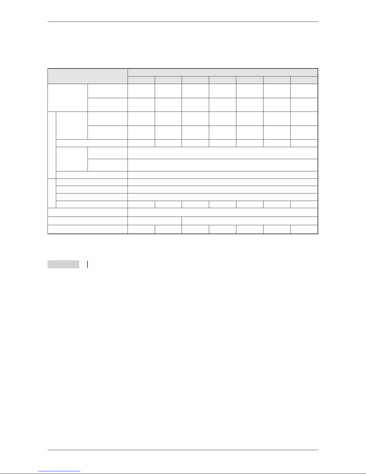
2.1 Model Specifications FR-E 520S EC
(1-phase connection)
NOTES Special notes referring to the table:
The applicable motor capacity refers to a motor voltage of 230V.
The overload capacity indicated in % is the ratio of the overload current to the inverter’s rated
current. For repeated duty, allow time for the inverter and motor to return to or below the tem
-
peratures under 100% load.
The maximum output voltage cannot exceed the power supply voltage. The maximum output
voltage may be set as desired below the power supply voltage.
The power supply capacity changes with the values of the power supply side inverter im
-
pedances (including those of the input reactor and cables).
Specifications
8 MITSUBISHI ELECTRIC
Type
FR-E 520S EC
0.4 k 0.75 k 1.5 k 2.2 k
Rated motor
capacity [kW]
150% Overload
capacity
0.75 1.1 2.2 3
200% Overload
capacity
0.4 0.75 1.5 2.2
Output
Rated
current [A]
150% Overload
capacity
3.6 5 9.6 12
200% Overload
capacity
2.5 4 7 10
Rated output capacity [kVA]
0.95 1.5 2.7 3.8
Overload
capacity
150% of rated motor capacity for 0.5s; 120% for 1min
(max. ambiente temperature 40°C)
200% of rated motor capacity for 0.5s; 150% for 1min
(max. ambiente temperature 50°C)
Voltage
3-phase, 0V up to power supply voltage
Input
Power supply voltage
1-phase, 200–240V AC, −15% / +10%
Permissible AC voltage fluctuation
170–264V AC at 50 / 60Hz
Power supply frequency
50 / 60Hz ± 5%
Rated input capacity [kVA]
1.5 2.3 4.0 5.2
Protection
IP 20
Cooling
Self-cooling Fan-cooling
Weight [kg]
1.9 1.9 2.0 2.0
2.2 Model Specifications FR-E 540 EC
(3-phase connection)
NOTES Special notes referring to the table:
The applicable motor capacity refers to a motor voltage of 400V.
The overload capacity indicated in % is the ratio of the overload current to the inverter’s rated
current. For repeated duty, allow time for the inverter and motor to return to or below the tem
-
peratures under 100% load.
The maximum output voltage cannot exceed the power supply voltage. The maximum output
voltage may be set as desired below the power supply voltage.
The power supply capacity changes with the values of the power supply side inverter im
-
pedances (including those of the input reactor and cables).
The rated output current in the parentheses applies when low acoustic noise operation is to
be performed at an ambient temperature higher than 40°C with the parameter 72 value set
to 2kHz or higher.
Specifications
FR-E 500 EC 9
Type
FR-E 540 EC
0.4 k 0.75 k 1.5 k 2.2 k 3.7 k 5.5 k 7.5 k
Rated motor
capacity [kW]
150% Overload
capacity
0.75 1.1 2.2 3 4 7.5 11
200% Overload
capacity
0.4 0.75 1.5 2.2 4 5.5 7.5
Output
Rated
current [A]
150% Overload
capacity
1.8 3 4.9 6.7 9.5 14 21
200 % Overload
capacity
1.6 (1.4) 2.6 (2.2) 4 (3.8) 6 (5.4) 9.5 (8.7) 12 17
Rated output capacity [kVA]
1.2 2.0 3.0 4.6 7.2 9.1 13.0
Overload
capacity
150% of rated motor capacity for 0.5s; 120% for 1min
(max. ambient temperature 40°C )
200% of rated motor capacity for 0.5s; 150% for 1min
(max. ambient temperature 50°C)
Voltage
3-phase, 0V up to power supply voltage
Input
Power supply voltage
3-phase, 380–480V AC, −15% / +10%
Voltage range
323–528V AC at 50 / 60Hz
Frequency range
50 / 60Hz ± 5%
Rated input capacity [kVA]
1.5 2.5 4.5 5.5 9 12 17
Protection
IP 20
Cooling
Self-cooling Fan-cooling
Weight [kg]
1.9 1.9 2.0 2.1 2.1 3.8 3.8
 Loading...