

Mitsubishi FR-E520-0.1K, FR-E520S, FR-E520-0.2K, FR-E520-0.4K, FR-E520-0.75K Instruction Manual
...
TRANSISTO RIZED INVERTER
FR-E
500
INSTRUCTION MANUAL
HIGH PERFORMANCE
&
HIGH FUNCTION
F R -E 5 20 -0 .1K to 7 .5K (C )
F R -E 5 40 -0 .4K to 7 .5K (C )
FR-E520S-0.1K to 0.75K
FR-E510W -0.1K to 0.75K
OUTLINE
INSTA LLATION
AND WIRING
OPERATION/
CONTROL
PARAMETERS
PROTECTIVE
FUNCTIONS
MAINTENANCE/
INSPECTION
Chapter 1
Chapter 2
Chapter 3
Chapter 4
Chapter 5
Chapter 6
SPECIFICATONS
Chapter 7
Thank you for choosing the Mitsubishi Transistorized inverter.
This instruction manual gives handling information and precautions for use of this
equipment.
Incorrect handling might cause an unexpected fault. Before using the inverter, please
read this manual carefully to use the equipment to its optimum.
Please forward this manual to the end user.
This section is specifically about safety matters
Do not attempt to install, operate, maintain or inspect the inverter until you have read
through this instruction manual and appended documents carefully and can use the
equipment correctly.
Do not use the inverter until you have a full knowledge of the equipment, safety
information and instructions.
In this manual, the safety instruction levels are classified into "WARNING" and
"CAUTION".
WARNING
CAUTION
Note that even the level may lead to a serious consequence
according to conditions. Please follow the instructions of both levels because they are
important to personnel safety.
Assumes that incorrect handling may cause hazardous
conditions, resulting in death or severe injury.
Assumes that incorrect handling may cause
hazardous conditions, resulting in medium or slight
injury, or may cause physical damage only.
CAUTION
A - 1

SAFETY INSTRUCTIONS
1. Electric Shock Prevention
! While power is on or when the inverter is running, do not open the front cover.
You may get an electric shock.
! Do not run the inverter with the front cover or wiring cover removed. Otherwise,
you may access the exposed high-voltage terminals or the charging part of the
circuitry and get an electric shock.
! If power is off, do not remove the front cover except for wiring or periodic
inspection. You may access the charged i nv erte r cir cuit s an d ge t an elec tric sh ock.
! Before starting wiring or inspection, check to make sure that the inverter power
indicator lamp is off, wait for at least 10 minutes after the power supply has been
switched off, and check that there are no residual voltage using a tester or the
like. The capacitor is charged with high voltage for some time after power off and
it is dangerous.
! This inverter must be earthed (grounded). Earthing (grounding) must conform to
the requirements of national and local safety regulations and electrical codes.
(JIS, NEC section 250, IEC 536 class 1 and other applicable standards)
! Any person who is involved in the wiring or inspection of this equipment should
be fully competent to do the work.
! Always install the inverter before wiring. Otherwise, you may get an electric
shock or be injured.
! Operate the switches and potentiometers with dry hands to prevent an electric
shock.
! Do not subject the cables to scratches, excessive stress, heavy loads or
pinching. Otherwise, you may get an electric shock.
! Do not change the cooling fan while power is on.
It is dangerous to change the cooling fan while power is on.
WARNING
2. Fire Prevention
CAUTION
! Mount the inverter and brake resistor on an incombustible surface. Installing the
inverter directly on or near a combustible surface could lead to a fire.
! If the inverter has become faulty, switch off the inverter power. A continuous flow
of large current could cause a fire.
! When a brake resistor is used, use an alarm signal to switch power off.
Otherwise, the brake resistor may excessively overheat due to damage of the
brake transistor and such, causing a fire.
! Do not connect a resistor directly to the DC terminals P(+), N(-). This could cause
a fire.
A - 2
3. Injury Prevention
CAUTION
! Apply only the voltage specified in the instruction manual to each terminal to
prevent damage etc.
! Ensure that the cables are connected to the correct terminals. Otherwise,
damage etc. may occur.
! Always make sure that polarity is correct to prevent damage etc.
! While power is on and for some time after power-off, do not touch the inverter or
brake resistor as they are hot and you may get burnt.
4. Additional Instructions
Also note the following points to prevent an accidental failure, injury, electric shock, etc.
(1) Transportation and installation
CAUTION
! When carrying products, use correct lifting gear to prevent injury.
! Do not stack the inverter boxes higher than the number recommended.
! Ensure that installation position and material can withstand the weight of the
inverter. Install according to the information in the Instruction Manual.
! Do not operate if the inverter is damaged or has parts missing.
! Do not hold the inverter by the front cover or operation panel; it may fall off.
! Do not stand or rest heavy objects on the inverter.
! Check the inverter mounting orientation is correct.
! Prevent screws, wire fragments or other conductive bodies or oil or other
flammable substance from entering the inverter.
! Do not drop the inverter, or subject it to impact.
! Use the inverter under the following environmental conditions:
Ambient
temperature
Ambient humidity 90%RH or less (non-condensing)
Storage
temperature
Ambience
Environment
Altitude, vibration
*Temper atures applicable for a short time, e.g. in transit.
-10°C to +50°C (non-freezing)
(-10°C to +40°C for totally enclosed structure feature)
-20°C to +65°C *
Indoors (free from corrosive gas, flammable gas, oil mist, dust
and dirt)
Maximum 1000m above sea level for standard operation. After
that derate by 3% for every extra 500m up to 2500m (91%).
2
5.9m/s
or less (conformin g to J IS C 004 0)
A - 3
(2) Wiring
CAUTION
! Do not fit capacitive equipment such as power factor correction capacitor, radio
noise filter or surge suppressor to the output of the inverter.
! The connection orientation of the output cables U, V, W to the motor will affect
the direction of rotation of the motor.
(3) Trial run
CAUTION
! Check all parameters, and ensure that the machine will not be damaged by a
sudden start-up.
(4) Operation
WARNING
! When you have chosen the retry function, stay away from t he equipment as it will
restart suddenly after an alarm stop.
! The [STOP] key is valid only when the appropriate function setting has been
made. Prepare an emergency stop switch separately.
! Make sure that the start signal is off before resetting the inverter alarm. A failure
to do so may restart the motor suddenly.
! The load used should be a three-phase induction motor only. Connection of any
other electrical equipment to the inverter output may damage the equipment.
! Do not modify the equipment.
! Do not perform parts removal which is not instructed in this manual. Doing so
may lead to fault or damage of the inverter.
A - 4
! The electronic thermal reray function does not guarantee protection of the motor
from overheating.
! Do not use a magnetic contactor on the inverter input for frequent starting/
stopping of the inverter.
! Use a noise filter to reduce the effect of electromagnetic interference. Otherwise
nearby electronic equipment may be affected.
! Take measures to suppress harmonics. Otherwise power supply harmonics from
the inverter may heat/damage the power capacitor and generator.
! When a 400V class motor is inverter-driven, it should be insulation-enhanced or
surge voltages suppressed. Surge voltages attributable to the wiring constants
may occur at the motor terminals, deteriorating the insulation of the motor.
! When parameter clear or all clear is performed, each parameter returns to the
factory setting. Re-set the required parameters before starting operation.
! The inverter can be easily set for high-speed operation. Before changing its
setting, fully examine the performances of the motor and machine.
! In addition to the inverter's holding function, install a holding device to ensure
safety.
! Before running an inverter which had been stored for a long period, always
perform inspection and test operation.
(5) Emergency stop
CAUTION
CAUTION
! Provide a safety backup such as an emergency brake which will prevent the
machine and equipment from hazardous conditions if the inverter fails.
! When the breaker on the inverter primary side trips, check for the wiring fault
(short circuit), damage to internal parts of the inverter, etc. Identify the cause of
the trip, then remove the cause and power on the breaker.
! When any protective function is activated, take the corrective appropriate action,
then reset the inverter, and resume operation.
(6) Maintenance, inspection and parts replacement
CAUTION
! Do not carry out a megger (insulation resistance) test on the control circuit of the
inverter.
(7) Disposing of the inverter
CAUTION
! Treat as industrial waste.
(8) General instructions
Many of the diagrams and drawings in this instruction manual show the inverter
without a cover, or partially open. Never operate the inverter in this manner. Always
replace the cover and follow this instruction manual when operating the inverter.
A - 5

CONTENTS
CHAPTER 1 OUTLINE 1
1.1 Pre-Operation Information.....................................................................................2
1.1.1 Precautions for operation.................................................................................. 2
1.2 Basic Configuration............................................................................................... 4
1.2.1 Basic configuration............................................................................................4
1.3 Structure .................................................................................................................5
1.3.1 Appearance and structure .................................................................................5
1.3.2 Removal and reinstallation of the front cover....................................................6
1.3.3 Removal and reinstallation of the wiring cover..................................................8
1.3.4 Removal and reinstallation of the operation panel ............................................ 9
1.3.5 Removal of the operation panel front cover.....................................................10
1.3.6 Exploded view .............................................................................................. ...11
CHAPTER 2 INSTALLATION AND WIRING 13
2.1 Installation ............................................................................................................ 14
2.1.1 Instructions for installation............................................................................... 14
2.2 Wiring....................................................................................................................16
2.2.1 Terminal connection diagram..................................................... ......... ......... ...16
2.2.2 Wiring of the Main Circuit................................................................................ 20
2.2.3 Wiring of the control circuit ..............................................................................25
2.2.4 Connection to the PU connector......................................................................29
2.2.5 Connection of stand-alone option units...........................................................33
2.2.6 Design information...........................................................................................37
2.3 Other Wiring..........................................................................................................38
2.3.1 Power supply harmonics................................................................................. 38
2.3.2 Harmonic suppression guideline..................................................................... 39
2.3.3 Inverter-generated noise and reduction techniques........................................42
2.3.4 Leakage currents and countermeasures......................................................... 46
2.3.5 Inverter-driven 400V class motor.....................................................................47
2.3.6 Peripheral devices........................................................................................... 48
2.3.7 Power off and magnetic contactor (MC).......................................................... 53
2.3.8 Instructions for UL, cUL................................................................................... 54
2.3.9 Instructions for compliance with the European Directive................................. 55
CHAPTER 3 OPERATION/CONTROL 57
3.1 Pre-Operation Information...................................................................................58
3.1.1 Types of operation modes............................................................................... 58
3.1.2 Power on......................................................................................................... 60
3.2 About the Operation Panel..................................................................................61
Contents
I

3.2.1 Names and functions of the operation panel................................................... 61
3.2.2 Monitor display is changed by pressing the [MODE] key................................ 62
3.2.3 Monitoring........................................................................................................62
3.2.4 Frequency setting............................................................................................ 63
3.2.5 Parameter setting method...............................................................................63
3.2.6 Operation mode...............................................................................................66
3.2.7 Help mode.......................................................................................................66
3.3 Operation.............................................................................................................. 68
3.3.1 Pre-operation checks.......................................................................................68
3.3.2 PU operation mode (Operation using the operation panel)............................. 69
3.3.3 External operation mode (Operation using the external frequency setting
potentiometer and external start signal)..........................................................71
3.3.4 Combined operation mode 1 (Operation using both external start signal and
operation panel).................................... .......... ......... ......... .......... ......... ......... ...72
3.3.5 Combined operation mode 2...........................................................................73
CHAPTER 4 PARAMETERS 75
4.1 Parameter List ...................................................................................................... 76
4.1.1 Parameter list.................................................................................................. 76
4.1.2 List of parameters classified by purpose of use..............................................82
4.1.3 Parameters recommended to be set by the user ............................................ 84
4.2 Parameter Function Details................................................................................. 85
4.2.1 Torque boost (Pr. 0, Pr. 46).............................................................................85
4.2.2 Output frequency range (Pr. 1, Pr. 2, Pr. 18)................................................... 86
4.2.3 Base frequency, base frequency voltage (Pr. 3, Pr. 19, Pr. 47)......................87
4.2.4 Multi-speed operation
(Pr. 4 to Pr. 6, Pr. 24 to Pr. 27, Pr. 232 to Pr. 239).......................................... 88
4.2.5 Acceleration/deceleration time (Pr. 7, Pr. 8, Pr. 20, Pr. 21, Pr. 44, Pr. 45)..... 89
4.2.6 Electronic thermal relay function (Pr. 9, Pr. 48)...............................................91
4.2.7 DC injection brake (Pr. 10 to Pr. 12)................................................................92
4.2.8 Starting frequency (Pr. 13).............................................................................. 93
4.2.9 Load pattern selection (Pr. 14)........................................................................94
4.2.10 Jog operation (Pr. 15, Pr. 16)..........................................................................95
4.2.11 Stall prevention and current restriction (Pr. 22, Pr. 23, Pr. 66, Pr. 156).......... 96
4.2.12 Acceleration/deceleration pattern (Pr. 29).......................................................99
4.2.13 Regenerative brake duty (Pr. 30, Pr. 70)....................................................... 100
4.2.14 Frequency jump (Pr. 31 to Pr. 36).................................................................101
4.2.15 Speed display (Pr. 37)................................................................................... 102
4.2.16 Frequency at 5V (10V) input (Pr. 38).............................................................103
4.2.17 Frequency at 20mA input (Pr. 39)................................................................. 103
4.2.18 Up-to-frequency sensitivity (Pr. 41) ...............................................................104
4.2.19 Output frequency detection (Pr. 42, Pr. 43)................................................... 104
II

4.2.20 Monitor display (Pr. 52, Pr. 54)......................................................................105
4.2.21 Monitoring reference (Pr. 55, Pr. 56)............................................................. 107
4.2.22 Automatic restart after instantaneous power failure
(Pr. 57, Pr. 58)............................................................................................... 108
4.2.23 Remote setting function selection (Pr. 59).....................................................110
4.2.24 Shortest acceleration/deceleration mode (Pr. 60 to Pr. 63)...........................113
4.2.25 Retry function (Pr. 65, Pr. 67 to Pr. 69).........................................................115
4.2.26 Applied motor (Pr. 71)................................................................................... 117
4.2.27 PWM carrier frequency and long wiring mode (Pr. 72, Pr. 240).................... 118
4.2.28 Voltage input (Pr. 73).....................................................................................120
4.2.29 Input filter time constant (Pr. 74)................................................................... 120
4.2.30 Reset selection/disconnected PU detection/PU stop selection (Pr. 75)........ 121
4.2.31 Parameter write disable selection (Pr. 77).....................................................123
4.2.32 Reverse rotation prevention selection (Pr. 78)..............................................124
4.2.33 Operation mode selection (Pr. 79).................................................................124
4.2.34 General-purpose magnetic flux vector control selection (Pr. 80)...................128
4.2.35 Offline auto tuning function (Pr. 82 to Pr. 84, Pr. 90, Pr. 96) ......................... 129
4.2.36 Computer link operation (Pr. 117 to Pr. 124, Pr. 342)...................................135
4.2.37 PID control (Pr. 128 to Pr. 134).....................................................................148
4.2.38 Frequency setting command selection (Pr. 146)...........................................156
4.2.39 Output current detection function (Pr. 150, Pr. 151)...................................... 157
4.2.40 Zero current detection (Pr. 152, Pr. 153).......................................................158
4.2.41 User group selection (Pr. 160, Pr. 173 to Pr. 176)........................................ 159
4.2.42 Actual operation hour meter clear (Pr. 171) .................................................. 161
4.2.43 Input terminal function selection (Pr. 180 to Pr. 183) .................................... 161
4.2.44 Output terminal function selection (Pr. 190 to Pr. 192)..................................163
4.2.45 Cooling fan operation selection (Pr. 244)......................................................164
4.2.46 Slip compensation (Pr. 245 to Pr. 247)..........................................................165
4.2.47 Earth (ground) fault detection at start (Pr. 249)
(400V class does not have this function)....................................................... 166
4.2.48 Stop selection (Pr. 250)................................................................................. 167
4.2.49 Output phase failure protection selection (Pr. 251)....................................... 168
4.2.50 Capacitor life alarm (Pr. 503, Pr. 504) (No function for the 400V class)........169
4.2.51 Meter (frequency meter) calibration (Pr. 900)................................................170
4.2.52 Biases and gains of the frequency setting voltage (current)
and built-in frequency setting potentiometer
(Pr. 902 to Pr. 905, Pr. 922, Pr. 923).............................................................172
CHAPTER 5 PROTECTIVE FUNCTIONS 185
5.1 Errors (Alarms)...................................................................................................186
5.1.1 Error (alarm) definitions................................................................................. 186
5.1.2 To know the operating status at the occurrence of alarm..............................195
5.1.3 Correspondence between digital and actual characters................................195
Contents
III

5.1.4 Resetting the inverter.................................................................................... 195
5.2 Troubleshooting.................................................................................................196
5.2.1 Motor remains stopped..................................................................................196
5.2.2 Motor rotates in opposite direction................................................................ 196
5.2.3 Speed greatly differs from the setting............................................................197
5.2.4 Acceleration/deceleration is not smooth........................................................ 197
5.2.5 Motor current is large.....................................................................................197
5.2.6 Speed does not increase...............................................................................197
5.2.7 Speed varies during operation.......................................................................197
5.2.8 Operation mode is not changed properly ...................................................... 198
5.2.9 Operation panel display is not operating.......................................................198
5.2.10 POWER lamp is not lit...................................................................................198
5.2.11 Parameter write cannot be performed...........................................................198
CHAPTER 6 MAINTENANCE/INSPECTION 199
6.1 Precautions for Maintenance and Inspection.................................................. 200
6.1.1 Precautions for maintenance and inspection.................................................200
6.1.2 Check items...................................................................................................200
6.1.3 Periodic inspection........................................................................................ 200
6.1.4 Insulation resistance test using megger........................................................201
6.1.5 Pressure test................................................................................................. 201
6.1.6 Daily and periodic inspection......................................................................... 202
6.1.7 Replacement of parts.................................................................................... 205
6.1.8 Measurement of main circuit voltages, currents and powers ........................ 210
CHAPTER 7 SPECIFICATIONS 213
7.1 Standard Specifications ....................................................................................214
7.1.1 Model specifications......................................................................................214
7.1.2 Common specifications................................................................................. 218
7.1.3 Outline drawings......................................................................... ......... ......... .220
APPENDIX 227
APPENDIX 1 Instruction Code List..........................................................................228
APPENDIX 2 When using the communication option. (400V class only).............232
IV

CHAPTER 1
OUTLINE
This chapter gives information on the basic "outline" of this
product.
Always read the instructions before using the equipment.
Chapter 1
1.1 Pre-Operation Informa tion............. ..........
1.2 Basic Configuration..................................
1.3 Structure..................................................
<Abbreviations>
•PU
Operation panel and parameter
unit (FR-PU04)
• Inverter
Mitsubishi transistorized inverter
FR-E500 series
•Pr.
Parameter number
1
2
4
Chapter 2
5
Chapter 3
Chapter 4
Chapter 5
Chapter 6
Chapter 7
OUTLINE
r
1.1 Pre-Operation Information
1.1.1 Precautions for operation
This manual is written for the FR-E500 series transistorized inverters.
Incorrect handling may cause the inverter to operate incorrectly, causing its life to be
reduced considerably, or at the worst, the inverter to be damaged. Handle the inverter
properly in accordance with the information in each section as well as the precautions
and instructions of this manual to use it correctly.
For handling information on the parameter unit (FR-PU04), stand-alone options, etc.,
refer to the corresponding manuals.
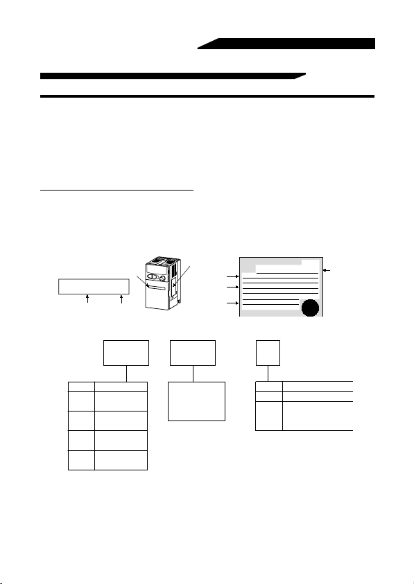
(1) Unpacking and product check
Unpack the inverter and check the capacity plate on the front cover and the rating plate
on the inverter side face to ensure that the product agrees with your order and the
inverter is intact.
1) Inverter type
Capacity plate
FR-E520-0.1K
Inverter type
!!!!
Inverter type
Capacity plate
Serial number
Rating plate
Input rating
Output rating
Serial number
Rating plate
MITSUBISHI
MODEL
FR-E520-0.1K
INPUT :
XXXXX
OUTPUT :
XXXXX
SERIAL :
INVERTER
PASSED
Inverte
type
FR -
E520 0.1
Symbol Voltage Class
Three-phase
E520
200V class
Three-phase
E540
400V class
Single-phase
E520S
200V class
Single-phase
E510W
100V class
- K -
Represents the
inverter capacity
"kW
".
Symbol
None
C
Protective Structure
Enclosed-type
Totally enclosed
structure
IP40
2) Accessory
Instruction manual
If you have found any discrepancy, damage, etc., please contact your sales
representative.
2

OUTLINE
(2) Preparation of instruments and parts required for operation
Instruments and parts to be prepared depend on how the inverter is operated. Prepare
equipment and parts as necessary. (Refer to page 58.)
(3) Installation
To operate the inverter with high performance for a long time, install the inverter in a
proper place, in the correct direction, with proper clearances. (Refer to page 14.)
(4) Wiring
Connect the power supply, motor and operation signals (control signals) to the terminal
block. Note that incorrect connection may damage the inverter and peripheral devices.
(See page 16.)
1
3
OUTLINE
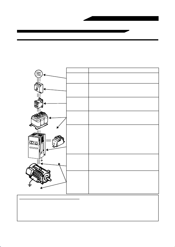
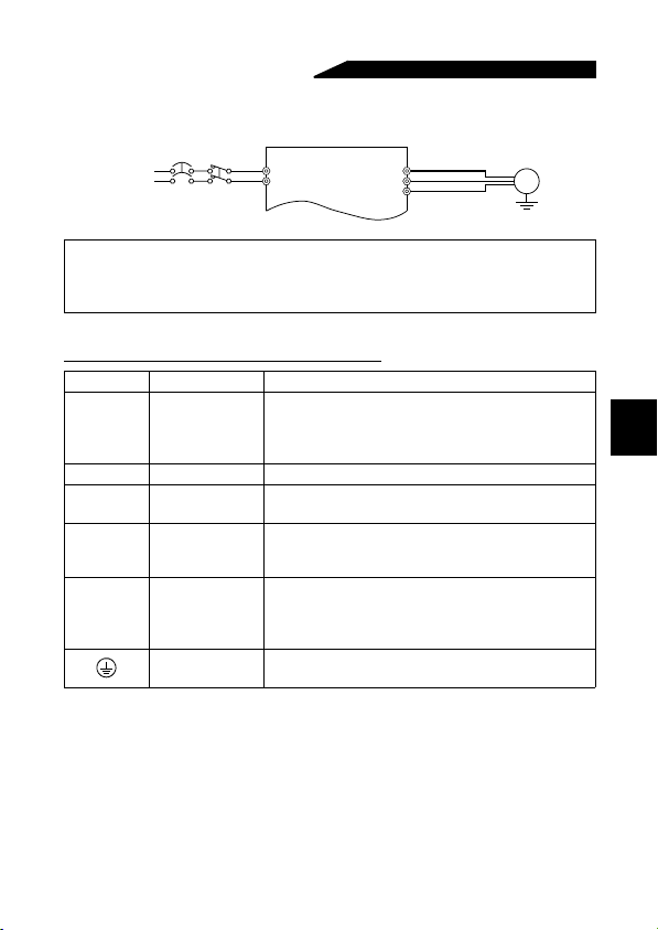
1.2 Basic Configuration
1.2.1 Basic configuration
The following devices are required to operate the inverter. Proper peripheral devices
must be selected and correct connections made to ensure proper operation. Incorrect
system configuration and connections can cause the inverter to operate improperly, its
life to be reduced considerably, and in the worst case, the inverter to be damaged.
Please handle the inverter properly in accordance with the information in each section
as well as the precautions and instructions of this manual. (For connections of the
peripheral devices, refer to the corresponding manuals.)
(NFB)
or
(ELB)
(MC)
AC
reactor
(FR-BAL)
DC reactor
(FR-BEL)
Earth (ground)
Earth (ground)
Harmonic Suppression Guideline
The "harmonic suppression guideline for household appliances and general-purpose products"
was issued by Ministry of Economy, Trade and Industry (formerly Ministry of International Trade
and Industry) in September, 1994. This guideline applies to the 3.7K* and less models of threephase 200V classes. By installing the power factor improving reactor (FR-BEL or FR-BAL),
inverters comply with the "harmonic suppression techniques for transistorized inverters (input
current 20A or less)" established by the Japan Electrical Manufacturers' Association.
* For the single-phase 200V class, the guideline applies to 2.2kW and less models.
For the single-phase 100V class, the guideline applies to 0.75kW and less models.
Name Description
Power supply
Earth (ground)
leakage circuit
breaker or nofuse breaker
Magnetic
contactor
Reactors
Inverter
Devices
connected to
the output
Earth (Ground)
Use the power supply within the permissible power
supply specifications of the inverter. (Refer to page
214.)
The breaker should be selected with care since a
large inrush current flows in the inverter at power
on. (Refer to page 48.)
Install for your safety. (Refer to page 53.) Do not
use this magnetic contactor to start or stop the
inverter. It might reduce the inverter life. (Refer to
page 48.)
The reactors must be used when the power factor is
to be improved or the inverter is installed near a large
power supply system (500KVA or more and wiring
distance within 10m). Make selection carefully.
• The life of the inverter is influenced by ambient
temperature. The ambient temperature should be
as low as possible within the permissible range.
This must be noted especially when the inverter is
installed in an en c los u r e . (Ref e r to pa ge 14 .)
• Wrong wiring might lead to damage of the
inverter. The contr ol sig nal li nes should be kept
away from the main circuit to protect them from
noise. (Refer to page 16.)
Do not connect a power capacitor, surge
suppressor or radio noise filter on the output side.
When installing a no-fuse breaker on the output
side of the inverter, contact each manufacturer for
selection of the no-fus e breaker.
To prevent an electric shock, always earth
(ground) the motor an d inverter.
For reduction of induction noise from the power
line of the inverter, it is recommended to wire the
earth (ground) cable by returning it to the earth
(ground) terminal of the inverter. (Refer to page
45.)
4
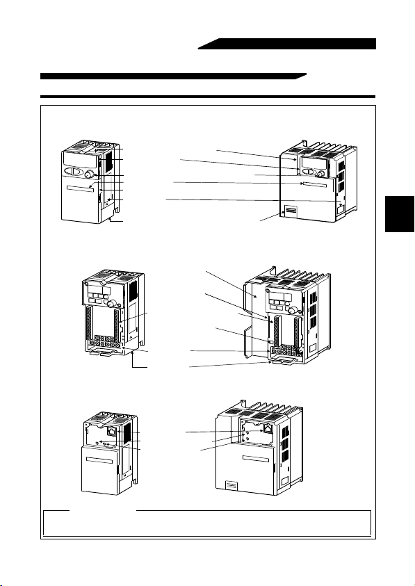
1.3 Structure
1.3.1 Appearance and str ucture
OUTLINE
(1) Front view
(100V class, 200V class)
Operation panel front cover
Operation panel
Built-in frequency setting potentiometer
Capacity plate
Front cover
Rating plate
Wiring cover
(2) Without front cover and operation panel f ront cover
(100V class, 200V class)
Inboard option
mounti ng position
Connector for connection
of inboard option
(400V class only)
Control circuit terminal block
Control logic changing
jumper connector
(400V class only)
Main circuit
terminal block
Wiring cover
(3) Without operation panel
PU connector
POWER lamp (yellow)
ALARM lamp (red)
Lamp indication
Power lamp.......Lit when power is spplied to the main circuit (R (L1),S (L2),T (L3)).
Alarm lamp........Lit when the inverter is in the alarm status (major faults).
Wiring port cover
for option
(400V class)100V class, 200V class)
(400V class)
(400V class)
1
5
OUTLINE
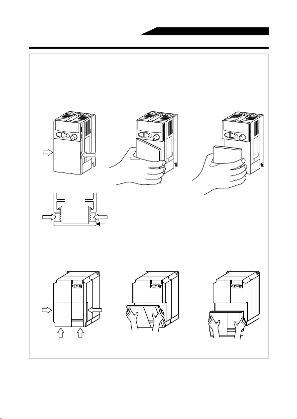
1.3.2 Removal and reinstallation of the front co ver
!!!!
Removal
(For the FR-E520-0.1K to 3.7K, FR-E520S-0.1K to 0.75K, FR-E510W-
0.1K to 0.75K)
The front cover is secured by hooks in positions A and B as shown below.
Push either A or B in the direction of arrows, and using the other end as a support,
pull the front cover toward you to remove.
1)
2) 3)
A
Overhead cross-sectional view
A
(For the FR-E520-5.5K, 7.5K)
The front cover is fixed with hooks in positions A, B and C.
Push A and B in the directions of arrows at the same time and remove the cover
using C as supporting points.
1)
A
CBC
B
B
Front cover
3)2)
6
OUTLINE
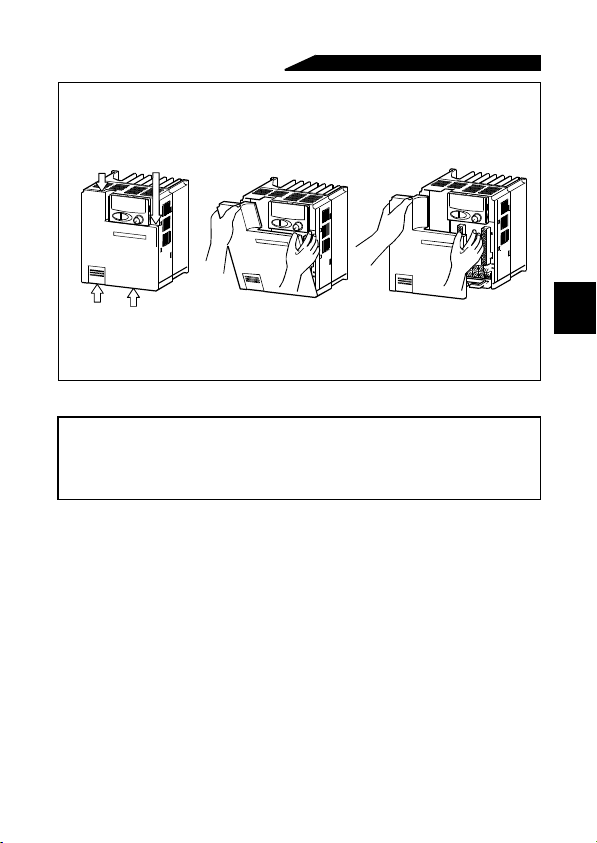
(For the FR-E540-0.4K to 7.5K)
The front cover is fixed with hooks in positions A, B and C.
Push A and B in the directions of arrows at the same time and remove the cover
using C as supporting points.
1) 2) 3)
B
A
C
C
!!!!
Reinstallation
When reinstalling the front cover after wiring, fix the hooks securely.
With the front cover removed, do not switch power on.
Note:1. Make sure that the front cover has been reinstalled securely.
2. The same serial number is printed on the capacity plate of the front cover
and the rating plate of the inverter. Before reinstalling the front cover, check
the serial numbers to ensure that the cover removed is reinstalled to the
inverter from where it was removed.
7
1
OUTLINE
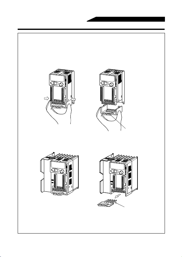
1.3.3 Removal and reinstallation of the wiri ng cover
!!!!
Removal
(For the FR-E520-0.1K to 7.5K, FR-E520S-0.1K to 0.75K, FR-E510W-
0.1K to 0.75K)
The wiring cover is fixed by hooks in positions 1) and 2).
Push either 1) or 2) in the direction of arrows and pull the wiring cover downward to
remove.
1)
(For the FR-E540-0.4K to 7.5K)
Remove the wiring cover by pulling it in the direction of arrow A.
!
!Reinstallation
!!
Pass the cables through the wiring hole and reinstall the cover in the original
position.
2)
Wiring hole
A
Wiring hole
8
OUTLINE
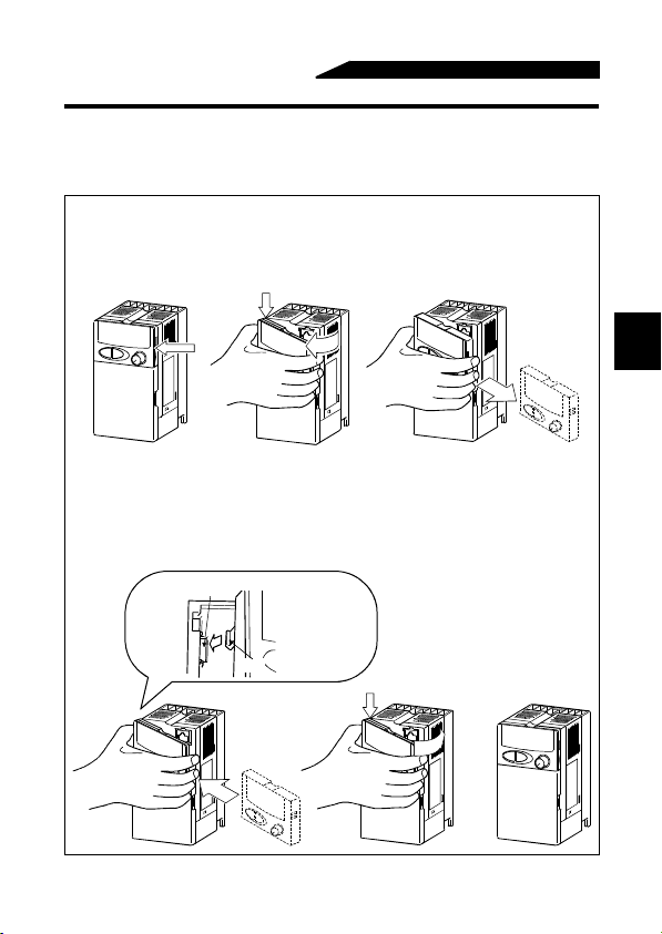
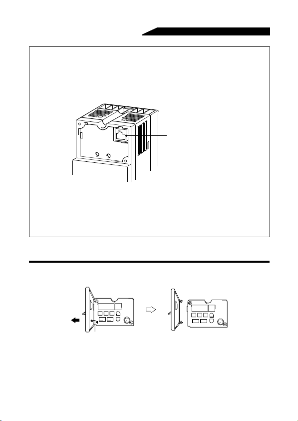
1.3.4 Removal and reinstallation of the operation panel
T o ensure safety , remove and reinstall the operation panel after swit chi ng power off.
The charging area and control printed board are exposed on the rear surface of the
operation panel. When removing the operation panel, always fit the rear cover option FR-
E5P. Never touch the control printed board because touching it can cause the inverter to fail
!!!!
Removal
Hold down the portion A indicated by the arrow and lift the right hand side using
the portion B indicated by the arrow as a support, and pull out the operation panel
to the right.
)
B
2)
3)
A
(If the above procedure is not used for removal, the internal connector may be
damaged by the force applied.)
!!!!
Reinstallation
Insert the mounting hook (left hand side) of the operation panel into the mounting
position of the inverter and push in the right hand side mounting hook to install the
operation panel.
Mounting position
Operation panel
Hook
1)
A
2)
3)
9
1
OUTLINE
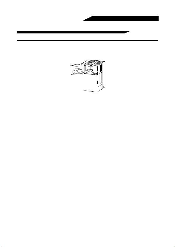
!!!!
Using the connection cable for operation
1) Remove the operation panel.
2) Fit the rear cover option FR-E5P to the back surface of the operation panel.
3) Securely plug one end of the connection cable into the PU connector of the
inverter and the other end into the adaptor of the FR-E5P option to connect it to
the operation panel. (For the connection cable of the FR-E5P, refer to page 29.)
PU connector
(RS-485 cable specifications)
!!!!
Mounting the operation panel on an enclosure
When you open the operation panel front cover, the screw mounting guides for
fixing the operation panel to an enclosure appear on the top left and bottom right.
Remove the operation panel, fit the rear cover of the FR-E5P option, drill holes in
the operation panel mounting guides, and securely mount the operation panel on
the enclosure with screws.
1.3.5 Removal of the operation panel front cover
1)Open the operation panel front cover to 90 degrees.
2)Pull out the operation panel front cover to the left to remove it.
90 degrees
10
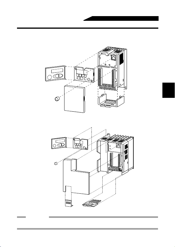
1.3.6 Exploded view
!!!!
FR-E520-0.1K to 7.5K
!!!!
FR-E520S-0.1K to 0.75K
!!!!
FR-E510W-0.1K to 0.75K
Operation panel
OUTLINE
1
Front cover
!!!!
FR-E540-0.4K to 7.5K
Operation panel
Front cover
Wiring port cover
for option
CAUTION
Do not remove any parts other than the operation panel, front cover, and wiring cover
Wiring cover
Wiring cover
from the inverter. Doing so will damage the inverter.
11

MEMO
12

CHAPTER 2
INSTALLATION AND
WIRING
This chapter gives information on the basic "installation and
wiring" for use of this product.
Always read the instructions in this chapter before using the
equipment.
Chapter 1
2.1 Installation................................................
2.2 Wiring.......................................................
2.3 Other Wiring.............................................
13
14
16
38
Chapter 2
Chapter 3
Chapter 4
Chapter 5
Chapter 6
Chapter 7
INSTALLATION AND WIRING
2.1 Installation
2.1.1 Instructions for installation
The FR-E520(S)-0.1K to 0.75K and FR-E510W-0.1K to 0.4K have top mounting holes
in the back of the operation panel front cover. Tighten the screws after opening the
cover.
1)Handle the unit carefully.
The inverter uses plastic parts. Handle it gently to protect it from damage.
Also, hold the unit with even strength and do not apply too much strength to the front
cover alone.
2) Install the inverter in a place where it is not affected by vibration easily (5.9m/s
maximum).
Note the vibration of a cart, press, etc.
3)Note on the ambient temperature.
The inverter life is under great influence of the ambient temperature. In the place of
installation, the ambient temperature must be within the permissible range -10°C to
+50°C (-10°C to +40°C when using the totally enclosed structure). Check that the
ambient temperature is within that range in the positions shown in figure 3).
4)Install the inverter on a non-combustible surface.
The inverter will be very hot (maximum about 150°C). Install it on a non-combustible
surface (e.g. metal). Also leave sufficient clearances around the inverter.
5)Avoid high temperature and high humidity.
Avoid direct sunlight and places of high temperature and high humidity.
6) Av oid places where the invert er is expos ed to oil mist, flammable gas es, fluff, dust,
dirt etc.
Install the inverter in a clean place or inside a "totally enclosed" panel which does not
accept any suspended matter.
2
14
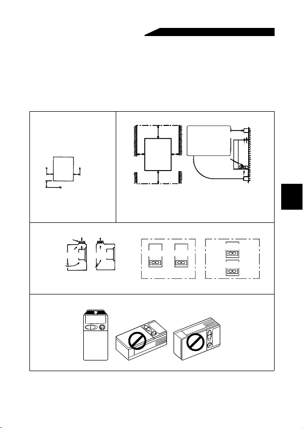
7)Note the cooling method when the inverter is installed in an enclosure.
INSTALLATION AND WIRING
When two or more inverters are installed or a ventilation fan is mounted in an
enclosure, the inverters and ventilation fan must be installed in proper positions with
extreme care taken to keep the ambient temperatures of the inverters with the
permissible values. If they are installed in improper positions, the ambient
temperatures of the inverters will rise and ventilation effect will be reduced.
8)Install the inverter securely in the vertical direction with screws or bolts.
3)Note on ambient
temperatures
Measurement
5cm
5cm
position
FR-E500
5cm
Measurement position
7)For installation in an enclosure
entilation
an
Inverter
Inverter
(Correct example) (Incorrect example)
Position of Ventilation Fan
8)Vertical mounting
4)Clearances around the inverter
10cm
Leave sufficient
or more
clearances above
and under the
inverter to ensure
adequate ventilation.
Cooling fan
1cm or
more*
*5cm or more for 5.5K and 7.5K
These clearances are also necessary for changing
the cooling fan.
(The 0.75K or more for 200V class and the 1.5K or
more for 400V class are provided with a cooling fan.)
1cm or
FR-E500
10cm
or more
Inverter
Built-in cooling fan
(Correct example)
When more than one inverter is contained
more*
Inverter
built in the
inverter
(Incorrect example)
15
Cooling air
2
Inverter
Inverter

INSTALLATION AND WIRING
2.2 Wiring
2.2.1 Terminal connection diagram
!!!!
3-phase 200V power input
!!!!
3-phase 400V power input
NFB
3-phase AC
power supply
24VDC power output and
external transistor common
Multi-speed selection
Control input signals
(No voltage input allowed)
Frequency setting signals (Analog)
(Note 1)
Frequency
setting
potentiometer
1/2W1kΩ
When using current input as the
frequency setting signal, set "4" in
any of Pr.180 to Pr.183 (input
terminal function selection) and
assign AU (current input selection)
to any of terminal RH, RM, RL, or
MRS, then turn the AU signal on.
Note:1. If the potentiometer is to be operated often, use a 2W1kΩ potentiometer.
2. 0.1K and 0.2K do not contain a transistor .
3. Terminals SD and SE are isolated.
4. Terminals SD and 5 are common terminals. Do not earth (ground) them to the
5. When terminals PC-SD are used as a 24VDC power supply, be careful not
6. Not needed when the operation panel or parameter unit (FR-PU04) is used for
MC
Forward rotation start
Reverse rotation start
Output stop
Contact input common
3
2
1
Current input(-)
4 to 20mADC(+)
R(L
S(L
T(L
PC
Note 5
STF
STR
High
RH
Middle
RM
RL
Low
MRS
RES
Reset
SD
Note 4
10(+5V)
0 to 5VDC
2
0 to 10VDC
(Common)
5
Note 4
4(4 to 20mADC)
Operation panel
(With frequency setting
potentiometer)
1
)
2
)
3
)
PU connector
(RS-485)
ground. Term inals SD and 5 are not isolated. (Those of the 400V class are isolated.)
to short these terminals. If they are shorted, the inverter will be damaged.
calibration. U sed when calibration must be made near the frequency meter for
such a reason as a remote frequency meter. However, the frequency meter
needle may not deflect to full-scale if the calibration resistor is connected. In this
case, use this resistor and the operation panel or parameter unit together.
Selected
U
V
W
P1
(+)P
PR
(-)N
Note 2
A
B
C
RUN
Running
FU
Frequency detection
SE
Note 3
(e.g. frequency meter)
FM
SD
Note 3
Alarm
output
Open collector
output common
Calibration
resistor (Note 6)
Jumper
Remove this jumper when
using the optional power-factor
improving DC reactor.
Brake resistor connection
Earth
(ground)
16
Motor
IM
Earth
(ground)
Open
collector outputs
Meter
+
-
Moving-coil type
1mA full-scale
Main circuit terminal
Control circuit input terminal
Control circuit output terminal
!!!! Single-phase 200V power input
)
INSTALLATION AND WIRING
!!!!
Single-phase 100V power input
NFB
Power supply
MC
R
S
U
V
W
Motor
IM
Earth
(ground
Note:1. To ensure safety, connect the power input to the inverter via a magnetic
contactor and earth (ground) leakage circuit breaker or no-fuse breaker, and
use the magnetic contactor to switch power on-off.
2. The output is three-phase 200V.
(1) Description of the main circuit terminals
Symbol Terminal Name Description
R, S, T
1
, L2, L3)
(L
U, V, W Inverter output Connect a three-phase squirrel-cage motor.
P (+), PR
P (+), N (-)
P (+), P1
(Note)
AC power input
Brake resistor
connection
Brake unit
connection
Power factor
improving
DC reactor
connection
Earth (Ground)
Note: R, S (L1, L2) terminals for single-phase power input.
Connect to the commercial power supply. Keep these
terminals open when using the high power factor
converter (FR-HC) or power regeneration common
converter (FR-CV).
Connect the optional brake resistor across terminals PPR (+ - PR) (not for 0.1K and 0.2K).
Connect the optional brake unit, high power factor
converter (FR-HC), and power regeneration common
converter (FR-CV).
Disconnect the jumper from terminals P-P1 ( + - P1) and
connect the optional power factor improving DC re actor.
(can not be connected to the single phase 100V power
input specification inverter)
For earthing (grounding) the inverter chassis. Must be
earthed (grounded).
2
17

INSTALLATION AND WIRING
(2) Description of the control circuit terminals
Type Symbol
RH, RM,
Contact input
Input signals
SD
PC
Analog
Frequency set tin g
Note: Assign the AU signal to any of the terminals using the input terminal function
selection (Pr. 180 to Pr. 183).
* Used as a contact input signal common terminal for the 400V class by switching
between sink logic and source logic. (Refer to page 26.)
Terminal
Name
Forward
STF
rotation start
Reverse
STR
rotation start
Multi-speed
selection
RL
MRS Output stop
RES Reset
Contact input
common
(sink*)
Power output
and external
transistor
common
Contact input
common
(source*)
Frequency
10
setting power
supply
Frequency
2
setting
(voltage)
Frequency
4
setting
(current)
Frequency
5
setting
common
Description
Turn on the STF signal to start forward
rotation and turn it off to stop.
Turn on the STR signal to start reverse
rotation and turn it off to stop.
Combine the RH, RM and RL signals as
appropriate to select multiple speeds.
Turn on the MRS signal (20ms or longer)
to stop the inverter output.
Used to shut off the inverter output to bring the
motor to a stop by the electromagn eti c brake.
Used to reset the protective circuit activated. Turn on the
RES signal for more than 0.1s then turn it off.
Factory setting is for reset always. By setting Pr.75, reset
can be set t o enabled only at an inverter alarm occurrence.
(Refer to page 121.) Recover about 1s after reset is
cancelled.
Common to the contact input terminals and terminal FM.
Common outpu t te rmi nal for 24VDC 0. 1A po we r o ut put ( PC
terminal).
When transistor output (open collector output), such as a
programmable controller (PLC), is connected, connect the
external power supply common for transistor output to this
terminal to preve nt a fau lt ca us e d by un de s ira bl e curre nt.
This terminal can be used as a 24VDC, 0.1A power output.
5VDC, permissi bl e lo ad cur ren t 10 mA
By entering 0 to 5VDC (0 to 10VDC), the maximum
output frequency is reached at 5V (or 10V) and I/O
are proportional. Use Pr. 73 to switch between input 0
to 5VDC (factory setting) and 0 to 10VDC. Input
resistance 10kΩ. Maximum permissible voltage 20V.
By entering 4 to 20mADC, the maximum output frequency is
reached at 20mA and I/O are proportional. This input signal
is valid only when the AU signal (Note) is on (voltage input is
invalid). Input resistance approximately 250Ω. Maximum
permissible current 30mA.
Common to the frequency setting signals (terminal 2, 1 or 4).
Do not connect to the earth (ground).
When the STF
and STR signals
are turned on
simultaneously,
the stop command
is given.
Input terminal
funct ion sel ect i on
(Pr. 180 to P r.
183) changes
termina l
functions.
18

INSTALLATION AND WIRING
Type Symbol
A, B, C Alarm output
Contact
RUN
Open collector
SE
Output signals
Pulse
PU connector
RS-485
Communication
*1: Low indicates that the open collector output transistor is on (conducts). High
indicates that the transistor is off (does not conduct).
Terminal
Name
Inverter
running
Frequency
FU
detection
Open collector
output common
FM For meter
Description
Change-over contact output indicating that
the output has b een s topp ed by t he inv ert er
protective function activated. 230VAC 0.3A,
30VDC 0.3A. Alarm: discontinuity across BC (continuit y across A-C), nor m al:
continuity across B-C (discontinuity across
A-C).
Switched low when the inve r ter ou tp ut
frequency is equal to or higher than the
starting frequency (factory set to 0.5Hz,
variable). Switched high during stop or DC
injection brake operation (*1).
Permissible lo a d 24 VD C 0. 1A.
Switched low whe n the output frequency
has reached or exc e eded the detection
frequency set as ap pro pr i at e. Swi tch ed
high when below the detection frequency
(*1).
Permissible lo a d 24 VD C 0. 1A
Common to the RU N an d FU term i na ls
One selected from output
frequency, motor current
and output voltage is output
(*2). The output signal is
proportional to the
magnitude of each
monitoring item.
With the operation panel connector, communication can
be made using the RS-485 protocol.
• Conforming Standard : EIA Standard RS-485
• Transmission format : Multi-drop link system
• Communication speed : Maximum 19200bps
• Overall length : 500m
Factory setti ng of output
item:
Frequency permissible
load current 1mA
1440 pulses/s at 60 Hz
Output
terminal
function
selection
(Pr. 190 to
Pr. 192)
changes
terminal
functions.
*2: Not output during inverter resetting.
2
19
INSTALLATION AND WIRING
2.2.2 Wiring of the Main Circuit
(1) Wiring instructions
1)It is recommended to use insulation-sleeved crimping terminals for power supply and
motor cables.
2)Application of power to the output terminals (U, V, W) of the inverter will damage the
inverter. Never perform such wiring.
3)After wiring, wire off-cuts must not be left in the inverter.
Wire off-cuts can cause an alarm, failure or malfunction. Always keep the inverter clean.
When drilling mounting holes in a control box etc., be careful so that chips and others
do not enter the inverter.
4)Use thick cables to make the voltage drop 2% or less.
If the wiring distance is long between the inverter and motor, a main circuit cable voltage
drop will cause the motor torque to decrease, especially at the output of a low frequency.
(A selection example for the wiring length of 20m is shown on page 23.)
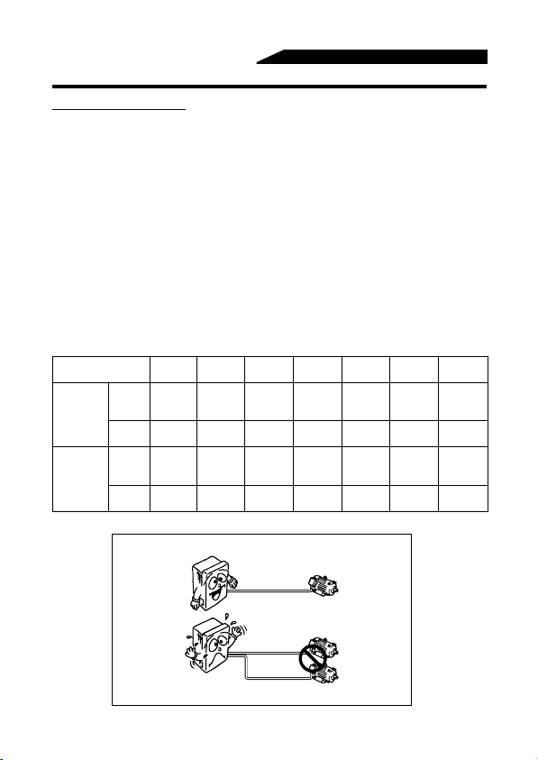
5) For long distance wiring, the overcurrent protection may be activated improperly or
the devices connected to the output side may misoperate or become faulty under the
influence of a charging current due to the stray capacitance of the wiring.
Therefore, the maximum overall wiring length should be as indicated in the following
table. If the wiring length exceeds the value, it is r ecom mended to set "1" in Pr. 156 to
make the high-response current limit function invalid. (When two or more motors are
connected to the inverter, the total wiring length should be withi n the indica ted val ue.)
Inverter
Capacity
Non-low
acoustic
noise
mode
Low
acoustic
noise
mode
0.1K 0.2K 0.4K 0.75K 1.5K 2.2K
100V,
200 200 300 500 500 500 500
200V
class
400V
—— —— 200 200 300 500 500
class
100V,
30 100 200 300 500 500 500
200V
class
400V
—— —— 30 100 200 300 500
class
Overall wiring length (3.7K or more)
3.7K or
more
(Unit: m)
500m maximum
300m
300m
300m+300m=600m
20
 Loading...