

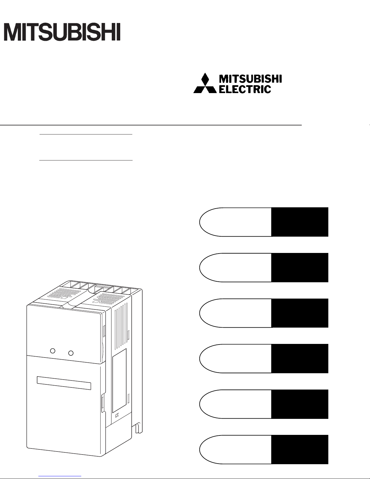
Mitsubishi Electric FR-E500, FR-E520, FR-E540, FR-E510W Instruction Manual
HIGH PERFORMANCE
&
HIGH FUNCTION
TRANSISTORIZED INVERTER
FR-E500
INSTRUCTION MANUAL
OUTLINE
OPERATION/
CONTROL
PARAMETERS
SPECIFICATIONS
INSTALLATION
AND WIRING
PROTECTIVE
FUNCTIONS
Chapter 6
Chapter 5
Chapter 4
Chapter 3
Chapter 2
Chapter 1
Thank you for choosing the Mitsubishi Transistorized inverter.
This instruction manual gives handling information and precautions for use of this
equipment.
Incorrect handling might cause an unexpected fault. Before using the inverter, please
read this manual carefully to use the equipment to its optimum.
Please forward this manual to the end user.
This section is specifically about safety matters
Do not attempt to install, operate, maintain or inspect the inverter until you have read
through this instruction manual and appended documents carefully and can use the
equipment correctly.
Do not use the inverter until you have a full knowledge of the equipment, safety
information and instructions.
In this manual, the safety instruction levels are classified into "WARNING" and
"CAUTION".
Assumes that incorrect handling may cause hazardous
WARNING
CAUTION
Note that even the CAUTION level may lead to a serious consequence according to
conditions. Please follow the instructions of both levels because they are important
to personnel safety.
conditions, resulting in death or severe injury.
Assumes that incorrect handling may cause hazardous
conditions, resulting in medium or slight injury, or may
cause physical damage only.
A - 1

SAFETY INSTRUCTIONS
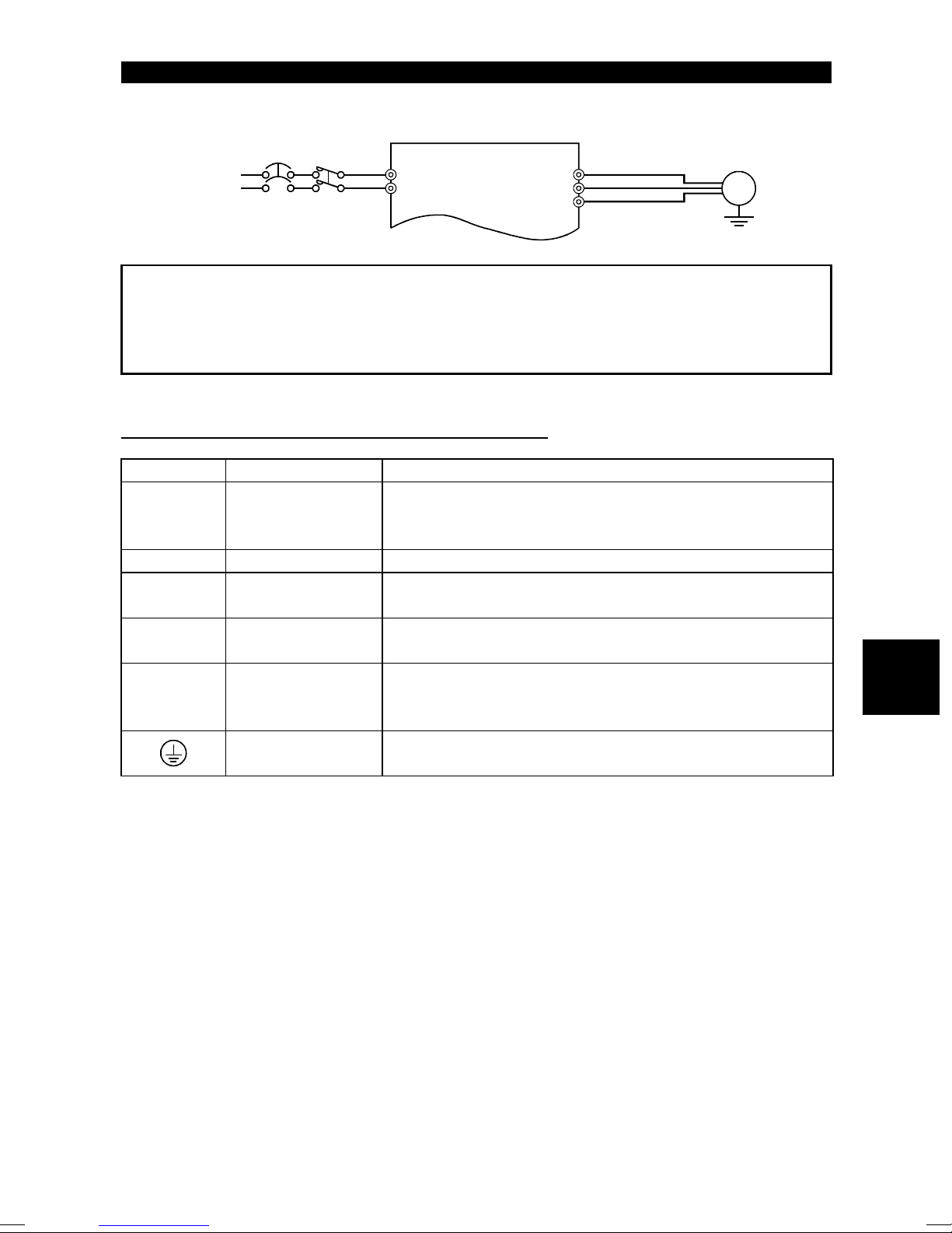
1. Electric Shock Prevention
WARNING
z
While power is on or when the inverter is running, do not open the front cover.
You may get an electric shock.
z
Do not run the inverter with the front cover removed. Otherwise, you may access
the exposed high-voltage terminals or the charging part of the circuitry and get
an electric shock.
z
If power is off, do not remove the front cover except for wiring or periodic
inspection. You may access the charged inverter circuits and get an electric
shock.
z
Before starting wiring or inspection, switch power off, wait for more than 10
minutes, and check for residual voltage with a meter (refer to chapter 2 for
further details) etc.
z
Earth the inverter.
z
Any person who is involved in the wiring or inspection of this equipment should
be fully competent to do the work.
z
Always install the inverter before wiring. Otherwise, you may get an electric
shock or be injured.
z
Operate the switches and potentiometers with dry hands to prevent an electric
shock.
z
Do not subject the cables to scratches, excessive stress, heavy loads or
pinching. Otherwise, you may get an electric shock.
z
Do not change the cooling fan while power is on.
It is dangerous to change the cooling fan while power is on.
2. Fire Prevention
z
Mount the inverter and brake resistor on an incombustible surface. Installing the
inverter directly on or near a combustible surface could lead to a fire.
z
If the inverter has become faulty, switch off the inverter power. A continuous
flow of large current could cause a fire.
z
When a brake resistor is used, use an alarm signal to switch power off.
Otherwise, the brake resistor will overheat abnormally due a brake transistor or
other fault, resulting in a fire.
z
Do not connect a resistor directly to the DC terminals P(+), N(−). This could
cause a fire.
CAUTION
A - 2
3. Injury Prevention
CAUTION
z
Apply only the voltage specified in the instruction manual to each terminal to
prevent damage etc.
z
Ensure that the cables are connected to the correct terminals. Otherwise,
damage etc. may occur.
z
Always make sure that polarity is correct to prevent damage etc.
z
While power is on and for some time after power-off, do not touch the inverter or
brake resistor as they are hot and you may get burnt.
4. Additional instructions
Also note the following points to prevent an accidental failure, injury, electric shock, etc.
(1)
Transportation and installation
CAUTION
z
When carrying products, use correct lifting gear to prevent injury.
z
Do not stack the inverter boxes higher than the number recommended.
z
Ensure that installation position and material can withstand the weight of the
inverter. Install according to the information in the Instruction Manual.
z
Do not operate if the inverter is damaged or has parts missing.
z
Do not hold the inverter by the front cover or operation panel; it may fall off.
z
Do not stand or rest heavy objects on the inverter.
z
Check the inverter mounting orientation is correct.
z
Prevent screws, wire fragments or other conductive bodies or oil or other
flammable substance from entering the inverter.
z
Do not drop the inverter, or subject it to impact.
z
Use the inverter under the following environmental conditions:
Ambient
temperature
Ambient humidity 90%RH or less (non-condensing)
Storage
temperature
Ambience
Environment
Altitude, vibration
*Temperatures applicable for a short time, e.g. in transit.
Constant torque : -10°C to +50°C (14°F to 122 °F)
(non-freezing)
-20°C to +65°C * (-4°F to 149 °F)
Indoors (free from corrosive gas, flammable gas, oil mist, dust
and dirt)
Maximum 1000m (3280. 80 feet) above sea level for standard
operation. After that derate by 3% f or every extra 500m
(1640.40 feet) up to 2500m (8202. 00 feet) (91%).
A - 3
(2)
Wiring
CAUTION
z
Do not fit capacitive equipment such as a power factor correction capacitor,
radio noise filter or surge suppressor to the output of the inverter.
z
The connection orientation of the output cables U, V, W to the motor will affect
the direction of rotation of the motor.
(3)
Trial run
CAUTION
z
Check all parameters, and ensure that the machine will not be damaged by a
sudden start-up.
(4)
Operation
WARNING
z
When you have chosen the retry function, stay away from the equipment as it
will restart suddenly after an alarm stop.
z
The [STOP] key is valid only when the appropriate function setting has been
made. Prepare an emergency stop switch separately.
z
Make sure that the start signal is off before resetting the inverter alarm. A failure
to do so may restart the motor suddenly.
z
The load used should be a three-phase induction motor only. Connection of any
other electrical equipment to the inverter output may damage the equipment.
z
Do not modify the equipment.
CAUTION
z
The electronic overcurrent protection does not guarantee protection of the
motor from overheating.
z
Do not use a magnetic contactor on the inverter input for frequent
starting/stopping of the inverter.
z
Use a noise filter to reduce the effect of electromagnetic interference. Otherwise
nearby electronic equipment may be affected.
z
Take measures to suppress harmonics. Otherwise power harmonics from the
inverter may heat/damage the power capacitor and generator.
A - 4
CAUTION
z
When a 400V class motor is inverter-driven, it should be insulation-enhanced or
surge voltages suppressed. Surge voltages attributale to the wiring constants
may occur at the motor terminals, deteriorating the insulation of the motor.
z
When parameter clear or all clear is performed, each parameter returns to the
factory setting. Re-set the required parameters before starting operation.
z
The inverter can be easily set for high-speed operation. Before changing its
setting, fully examine the performances of the motor and machine.
z
In addition to the inverter's holding function, install a holding device to ensure
safety.
z
Before running an inverter which had been stored for a long period, always
perform inspection and test operation.
(5)
Emergency stop
CAUTION
z
Provide a safety backup such as an emergency brake which will prevent the
machine and equipment from hazardous conditions if the inverter fails.
(6)
Maintenance, inspection and parts replacement
CAUTION
z
Do not carry out a megger (insulation resistance) test on the control circuit of
the inverter.
(7)
Disposing of the inverter
CAUTION
z
Treat as industrial waste.
(8) General
Many of the diagrams and drawings in this instruction manual show the inverter
without a cover, or partially open. Never operate the inverter like this. Always
replace the cover and follow this instruction manual when operating the inverter.
instructions
A - 5

CONTENTS
1 OUTLINE 1
1.1 Pre-Operation Information.......................................................................................... 1
1.1.1 Precautions for operation..................................................................................... 1
1.2 Basic Configuration.................................................................................................... 3
1.2.1 Basic configuration .............................................................................................. 3
1.3 Structure..................................................................................................................... 4
1.3.1 Appearance and structure ................................................................................... 4
1.3.2 Removal and reinstallation of the front cover ...................................................... 5
1.3.3 Removal and reinstallation of the wiring cover.................................................... 7
1.3.4 Removal and reinstallation of the accessory cover.............................................. 8
1.3.5 Reinstallation and removal of the control panel................................................... 9
1.3.6 Removal of the control panel (FR-PA02-02) front cover..................................... 10
Contents
1.3.7 Exploded view.................................................................................................... 11
2 INSTALLATION AND WIRING 12
2.1 Installation................................................................................................................12
2.1.1 Instructions for installation................................................................................. 12
2.2 Wiring....................................................................................................................... 14
2.2.1 Terminal connection diagram ............................................................................ 14
2.2.2 Wiring of the main circuit ................................................................................... 18
2.2.3 Wiring of the control circuit ................................................................................ 23
2.2.4 Connection to the PU connector........................................................................ 28
2.2.5 Connection of stand-alone option units ............................................................. 31
2.2.6 Design information............................................................................................. 34
2.3 Other Wiring............................................................................................................. 35
2.3.1 Power supply harmonics.................................................................................... 35
2.3.2 Japanese harmonic suppression guideline........................................................ 36
2.3.3 Inverter-generated noise and reduction techniques........................................... 36
2.3.4 Leakage currents and countermeasures........................................................... 40
2.3.5 Inverter-driven 400V class motor....................................................................... 41
2.3.6 Peripheral devices............................................................................................. 42
2.3.7 Instructions for compliance with the UL and CSA standards............................. 46
2.3.8 Instructions for compliance with the European standards................................. 47
I

3 OPERATION/CONTROL 49
3.1 Pre-Operation Information........................................................................................ 49
3.1.1 Types of operation modes................................................................................. 49
3.1.2 Power on............................................................................................................ 51
3.2 About the Control Panel........................................................................................... 52
3.2.1 Names and functions of the control panel (FR-PA02-02)................................... 52
3.2.2 Control panel mode is changed by pressing the
MODE
key ................................ 53
3.2.3 Monitoring.......................................................................................................... 53
3.2.4 Frequency setting.............................................................................................. 54
3.2.5 Parameter setting method ................................................................................. 54
3.2.6 Operation mode................................................................................................. 56
3.2.7 Help mode ......................................................................................................... 56
3.3 Operation ................................................................................................................. 59
3.3.1 Pre-operation checks......................................................................................... 59
3.3.2 External operation mode (Operation using the external
frequency setting potentiometer and external start signal)................................ 60
3.3.3 PU operation mode (Operation using the control panel).................................... 61
3.3.4 Combined operation mode 1
(Operation using both external start signal and control panel).......................... 62
3.3.5 Combined operation mode 2 ............................................................................. 63
4 PARAMETERS 64
4.1 Parameter List.......................................................................................................... 64
4.1.1 Parameter list..................................................................................................... 64
4.1.2 List of parameters classified by purpose of use................................................. 70
4.1.3 Parameters recommended to be set by the user............................................... 72
4.2 Parameter Function Details...................................................................................... 73
4.2.1 Torque boost (Pr. 0, Pr. 46)............................................................................... 73
4.2.2 Output frequency range (Pr. 1, Pr. 2, Pr. 18)..................................................... 74
4.2.3 Base frequency, base frequency voltage (Pr. 3, Pr. 19, Pr. 47)......................... 75
4.2.4 Multi-speed operation (Pr. 4, Pr. 5, Pr. 6, Pr. 24 to Pr. 27, Pr. 232 to Pr. 239). 76
4.2.5 Acceleration/deceleration time (Pr. 7, Pr. 8, Pr. 20, Pr. 21, Pr. 44, Pr. 45)....... 77
4.2.6 Electronic overcurrent protection (Pr. 9, Pr. 48)................................................. 79
4.2.7 DC dynamic brake (Pr. 10 to Pr. 12).................................................................. 80
II

4.2.8 Starting frequency (Pr. 13)................................................................................. 81
4.2.9 Load pattern selection (Pr. 14) .......................................................................... 82
4.2.10 Jog operation (Pr. 15, Pr. 16) .......................................................................... 83
4.2.11 Stall prevention (Pr. 22, Pr. 23, Pr. 66)............................................................ 84
4.2.12 Acceleration/deceleration pattern (Pr. 29) ....................................................... 86
4.2.13 Regenerative brake duty (Pr. 30, Pr. 70)......................................................... 87
4.2.14 Frequency jump (Pr. 31 to Pr. 36).................................................................... 88
4.2.15 Speed display (Pr. 37)..................................................................................... 89
4.2.16 Frequency at 5V (10V) input (Pr. 38)............................................................... 90
4.2.17 Frequency at 20mA input (Pr. 39).................................................................... 90
4.2.18 Up-to-frequency sensitivity (Pr. 41).................................................................. 91
4.2.19 Output frequency detection (Pr. 42, Pr. 43)..................................................... 91
4.2.20 Monitor display (Pr. 52, Pr. 54, Pr. 158)........................................................... 93
4.2.21 Monitoring reference (Pr. 55, Pr. 56) ............................................................... 95
4.2.22 Automatic restart after instantaneous power failure
(Pr. 57, Pr. 58).................................................................................................. 96
4.2.23 Remote setting function selection (Pr. 59)....................................................... 97
4.2.24 Shortest acceleration/deceleration mode (Pr. 60 to Pr. 63)............................. 98
4.2.25 Retry function (Pr. 65, Pr. 67 to Pr. 69) ......................................................... 100
Contents
4.2.26 Applied motor (Pr. 71).................................................................................... 102
4.2.27 PWM carrier frequency (Pr. 72, Pr. 240) ....................................................... 103
4.2.28 Voltage input (Pr. 73)..................................................................................... 104
4.2.29 Input filter time constant (Pr. 74).................................................................... 105
4.2.30 Reset selection/PU disconnection detection/PU stop
selection (Pr. 75)............................................................................................ 105
4.2.31 Parameter write inhibit selection (Pr. 77)....................................................... 107
4.2.32 Reverse rotation prevention selection (Pr. 78)............................................... 108
4.2.33 Operation mode selection (Pr. 79)................................................................. 109
4.2.34 General-purpose magnetic flux v ector control selection (Pr . 80)........................ 112
4.2.35 Offline auto tuning function (Pr. 82 to Pr. 84, Pr. 90, Pr. 96) ......................... 114
4.2.36 Computer link operation (Pr. 117 to Pr. 124)................................................. 120
4.2.37 PID control (Pr. 128 to Pr. 134) ..................................................................... 131
4.2.38 Output current detection function (Pr. 150, Pr.151)....................................... 139
4.2.39 Zero current detection (Pr. 152, Pr.153)........................................................ 140
4.2.40 Stall prevention function and current limit function (Pr. 156)......................... 141
III

4.2.41 User group selection (Pr. 160, Pr. 173 to Pr. 176)......................................... 143
4.2.42 Actual operation hour meter clear (Pr. 171)................................................... 145
4.2.43 Input terminal function selection (Pr. 180 to Pr. 183)..................................... 145
4.2.44 Output terminal function selection (Pr. 190 to Pr. 192).................................. 147
4.2.45 Cooling fan operation selection (Pr. 244) ...................................................... 148
4.2.46 Slip compensation (Pr. 245 to Pr. 247).......................................................... 149
4.2.47 Ground fault detection at start (Pr. 249)
(400V class does not have this function)....................................................... 150
4.2.48 Stop selection (Pr. 250)................................................................................. 151
4.2.49 Meter (frequency meter) calibration (Pr. 900) (200V class, 100V class)....... 153
4.2.50 Meter (frequency meter) calibration (Pr. 901) (400V class)........................... 155
4.2.51 Biases and gains of the frequency setting voltage (current)
(Pr. 902 to Pr. 905) ........................................................................................ 157
5 PROTECTIVE FUNCTIONS 163
5.1 Errors (Alarms)....................................................................................................... 163
5.1.1 Error (alarm) definitions................................................................................... 163
5.1.2 To know the operating status at the occurrence of alarm................................ 171
5.1.3 Correspondence between digital and actual characters.................................. 171
5.1.4 Resetting the inverter....................................................................................... 171
5.2 Troubleshooting ..................................................................................................... 172
5.2.1 Motor remains stopped.................................................................................... 172
5.2.2 Motor rotates in opposite direction................................................................... 172
5.2.3 Speed greatly differs from the setting.............................................................. 173
5.2.4 Acceleration/deceleration is not smooth.......................................................... 173
5.2.5 Motor current is large....................................................................................... 173
5.2.6 Speed does not increase................................................................................. 173
5.2.7 Speed varies during operation......................................................................... 173
5.2.8 Operation mode is not changed properly......................................................... 174
5.2.9 Control panel display is not operating.............................................................. 174
5.2.10 POWER lamp is not lit................................................................................... 174
5.2.11 Parameter write cannot be performed........................................................... 174
5.3 Precautions for Maintenance and Inspection......................................................... 175
5.3.1 Precautions for maintenance and inspection................................................... 175
5.3.2 Check items..................................................................................................... 175
IV

5.3.3 Periodic inspection........................................................................................... 175
5.3.4 Insulation resistance test using megger........................................................... 176
5.3.5 Pressure test.................................................................................................... 176
5.3.6 Daily and Periodic Inspection .......................................................................... 177
5.3.7 Replacement of parts....................................................................................... 180
5.3.8 Measurement of main circuit voltages, currents and powers........................... 185
6 SPECIFICATIONS 188
6.1 Standard Specifications ......................................................................................... 188
6.1.1 Model specifications ........................................................................................ 188
6.1.2 Common specifications.................................................................................... 191
6.1.3 Outline drawings.............................................................................................. 193
APPENDIX 199
Appendix 1 Data Code List........................................................................................... 199
Contents
V

C H A P T E R 1
CHAPTER 1
O U T L I N E
OUTLINE
This chapter gives information on the basic "outline" of this
product.
Always read the instructions before using the equipment.
1.1 Pre-Operation Information ..........................................1
1.2 Basic Configuration.....................................................3
1.3 Structure.....................................................................4
<Abbreviations>
y PU
Control panel and parameter
unit (FR-PU04)
y Inverter
Mitsubishi transistorized inverter
FR-E500 series
y Pr.
Parameter number
Chapter 1
Chapter 2
Chapter 3
Chapter 4
Chapter 5
Chapter 6
1.1 Pre-Operation Information
g
g
OUTLINE
1 OUTLINE
1.1 Pre-Operation Information
1.1.1 Precautions for operation
This manual is written for the FR-E500 series transistorized inverters.
Incorrect handling may cause the inverter to operate incorrectly, causing its life to be
reduced considerably, or at the worst, the inverter to be damaged. Handle the inverter
properly in accordance with the information in each section as well as the precautions
and instructions of this manual to use it correctly.
For handling information on the parameter unit (FR-PU04), stand-alone options, etc.,
refer to the corresponding manuals.
(1)
Unpacking and product check
Unpack the inverter and check the capacity plate on the front cover and the rating plate
on the inverter side face to ensure that the product agrees with your order and the
inverter is intact.
1) Inverter type
Capacity plate
FR-E520-0.1K-NA/
Inverter type
z Inverter type
FR -
Symbol Voltage Class
E520
E540
E510W
E520
Three-phase
200V class
Three-phase
400V class
Single-phase
100V class
Capacity plate
Serial number
Rating plate
MITSUBISHI
Rating plate
Input ratin
Output ratin
Serial number
MODEL
FR-E520-0.1K-NA
INPUT :
XXXXX
OUTPUT :
XXXXX
SERIAL :
-0.1K - NA
Represents the
inverter capacity
"kW
".
INVERTER
Inverter type
PASSED
2) Accessory
Instruction manual
If you have found any discrepancy, damage, etc., please contact your sales
representative.
1

OUTLINE
(2)
Preparation of instruments and parts required for operation
Instruments and parts to be prepared depend on how the inverter is operated. Prepare
equipment and parts as necessary. (Refer to page 49.)
(3)
Installation
To operate the inverter with high performance for a long time, install the inverter in a
proper place, in the correct direction, with proper clearances. (Refer to page 12.)
(4)
Wiring
Connect the power supply, motor and operation signals (control signals) to the terminal
block. Note that incorrect connection may damage the inverter and peripheral devices.
(See page 14.)
1
2
1.2 Basic Configuration
A
OUTLINE
1.2 Basic Configuration
1.2.1 Basic configuration
The following devices are required to operate the inverter. Proper peripheral devices
must be selected and correct connections made to ensure proper operation. Incorrect
system configuration and connections can cause the inverter to operate improperly, its
life to be reduced considerably, and in the worst case, the inverter to be damaged.
Please handle the inverter properly in accordance with the information in each section
as well as the precautions and instructions of this manual. (For connections of the
peripheral devices, refer to the corresponding manuals.)
Name Description
Use the power supply within the
permissible power supply specifications
of the inverter. (Refer to page 188.)
The breaker should be selected with
care since a large inrush current flows
in the inverter at power on. (Refer to
page 42.)
Do not use this magnetic contactor to
start or stop the inverter. It might reduce
the inverter life. (Refer to page 42.)
The reactors must be used when the
power factor is to be improved or the
inverter is installed near a large power
supply system (1000KVA or more and
wiring distance within 10m (32.81 feet)).
Make selection carefully.
•
The inverter life is influenced by
ambient temperature. The ambient
temperature should be as low as
possible within the permissible range.
This must be noted especially when
the inverter is installed in an enclosure.
(Refer to page 12.)
•
Wrong wiring might lead to inverter
damage. The control signal lines should
be kept away from the main circuit to
protect them from noise. (Refer to page
14.)
Do not connect a power capacitor,
surge suppressor or radio noise
filter to the output side.
To prevent an electric shock, always
ground the motor and inverter.
(NFB)
(ELB)
C reactor
(FR-BAL)
Ground
or
(MC)
Power
supply
Earth leakage
circuit breaker
or no-fuse
breaker
Magnetic
contactor
Reactors
DC reactor
(FR-BEL)
Inverter
Ground
Devices
connected
to the output
Ground
Japanese Harmonic Suppression Guideline
The "harmonic suppression guideline for household appliances and general-purpose
products" was issued by the Ministry of International Trade and Industry in September,
1994. This guideline applies to the 3.7K* and less models of three-phase 200V classes.
By installing the power factor improving reactor (FR-BEL or FR-BAL), inverters comply
with the "harmonic suppression techniques for transistorized inverters (input current 20A
or less)" established by the Japan Electrical Manufacturers' Association.
* For the single-phase 100V class, the guideline applies to 0.75kW and less models.
3

1.3 Structure
g
g
g
g
g
g
1.3 Structure
1.3.1 Appearance and structure
(1) Front view
OUTLINE
(100V class, 200V class)
POWER lamp
(yellow)
Accessory cover
ALARM lamp (red)
Capacity plate
Ratin
plate
Front cover
Wirin
port cover
for option
(2) Without accessory cover and front cover
(100V class, 200V class)
Inboard opt i on
mountin
PU conector*
POWER lamp (yellow)
ALARM lamp (red)
Connector for connection
of inboard option
(400V class only )
Control circuit
terminal block
Control lo
connector
Main circuit
terminal block
Wirin
position
ic changin
cover
(400V class)
1
(400V class)
*Use the PU connector for the FR-PA02
communication.
-02
or FR-PU04 option and RS-485
4
OUTLINE
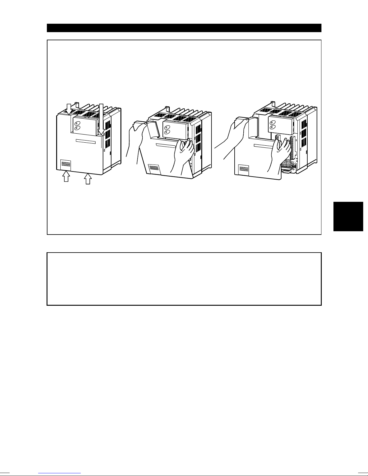
1.3.2 Removal and reinstallation of the front cover
z Removal
(For the FR-E520-0.1K to 3.7K-NA, FR-E510W-0.1K to 0.75K-NA)
The front cover is secured by catches in positions A and B as shown below.
Push either A or B in the direction of arrows, and using the other end as a
support, pull the front cover toward you to remove.
1) 2) 3)
A
B
(For the FR-E520-5.5K, 7.5K-NA)
The front cover is fixed with catches in positions A, B and C.
Push A and B in the directions of arrows at the same time and remove the
cover using C as supporting points.
1) 2) 3)
A
C
C
B
5
OUTLINE
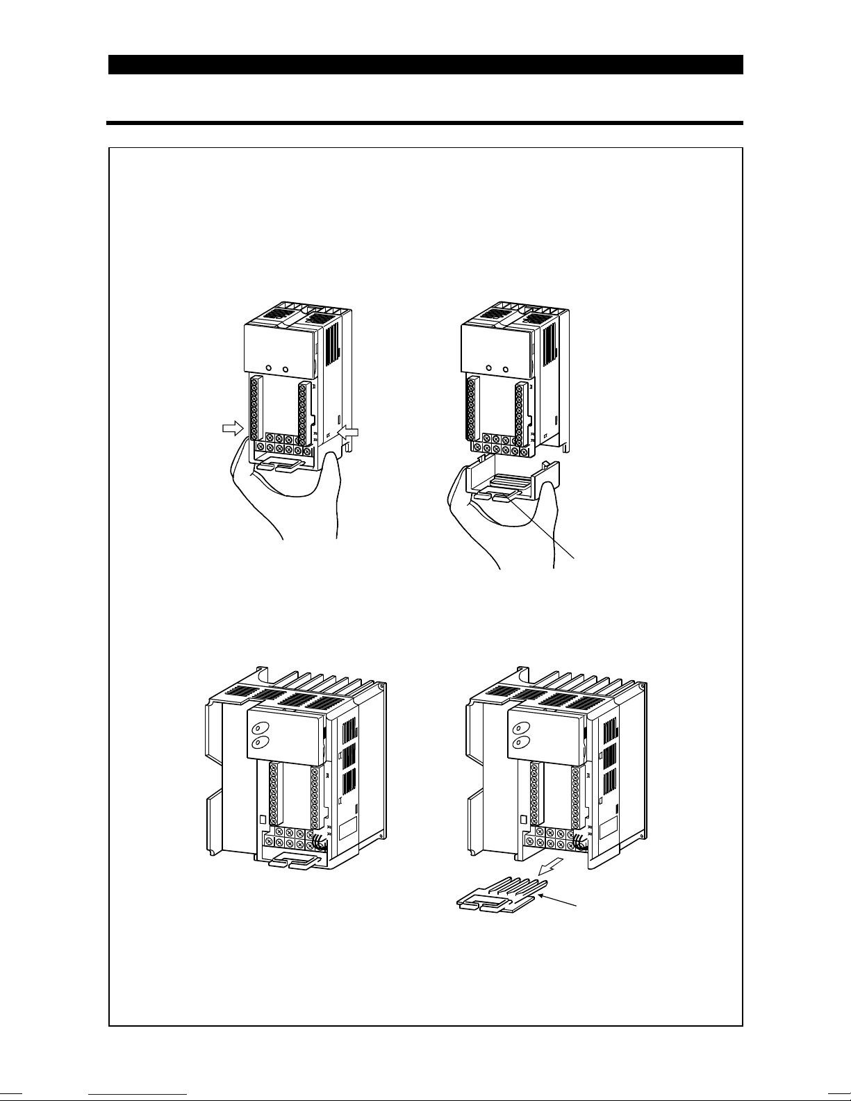
(For the FR-E540-0.4K to 7.5K-NA)
The front cover is fixed with catches in positions A, B and C.
Push A and B in the directions of arrows at the same time and remove the
cover using C as supporting points.
1)
C
A B
C
2) 3)
z Reinstallation
When reinstalling the front cover after wiring, fix the catches securely.
With the front cover removed, do not switch power on.
Note:1. Make sure that the front cover has been reinstalled securely.
2. The same serial number is printed on the capacity plate of the front cover
and the rating plate of the inverter. Before reinstalling the front cover, check
the serial numbers to ensure that the cover removed is reinstalled to the
inverter from where it was removed.
1
6
OUTLINE
1.3.3 Removal and reinstallation of the wiring cover
z
Removal
(For the FR-E520-0.1K to 7.5K-NA, FR-E510W-0.1K to 0.75K-NA)
The wiring cover is fixed by catches in positions 1) and 2).
Push either 1) or 2) in the direction of arrows and pull the wiring cover
downward to remove.
1)
2)
(For the FR-E540-0.4K to 7.5K-NA)
Remove the wiring cover by pulling it in the direction of arrow A.
Wiring hole
z
Reinstallation
Pass the cables through the wiring hole and reinstall the cover in the original
position.
A
Wiring hole
7

OUTLINE
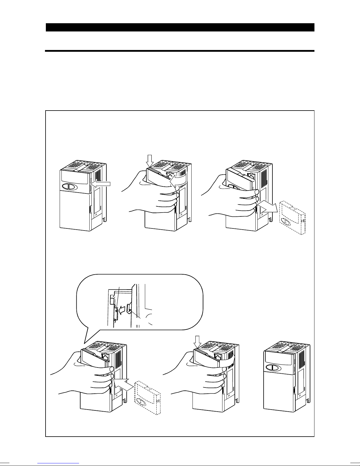
1.3.4 Removal and reinstallation of the accessory cover
z
Removal of the accessory cover
Hold down the portion A indicated by the arrow and lift the right hand side using
the portion B indicated by the arrow as a support, and pull out the accessory
cover to the right.
1)
z
Reinstallation of the accessory cover
2)
A
B
3)
Insert the mounting catch (left hand side) of the accessory cover into the
mounting position of the inverter and push in the right hand side mounting
catch to install the accessory cover.
Mounting position
1
1)
Accessory cover
Catch
2)
A
3)
8
OUTLINE
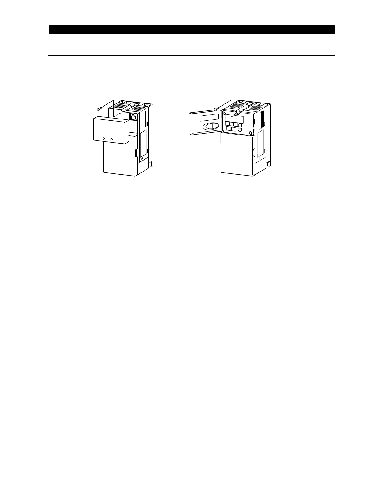
1.3.5 Reinstallation and removal of the control panel
To ensure safety, reinstall and removal the optional control panel (FR-PA02-02) after
switching power off.
The charging area and control printed board are exposed on the rear surface of the
control panel. When removing the control panel, always fit the rear cover option
FR-E5P. Never touch the control printed board because touching it can cause the
inverter to fail.
z
Reinstallation of the control panel
Insert the mounting catch (left hand side) of the control panel into the
mounting position of the inverter and push in the right hand side mounting
catch to install the control panel.
1) 2)
A
B
3)
z
Removal of the control panel
Hold down the portion A indicated by the arrow and lift the right hand side
using the portion B indicated by the arrow as a support, and pull out the
control panel to the right.
Mounting position
2)
02
A
3)
FR-PA02-
Catch
1)
(If the above procedure is not used for removal, the internal connector may be
damaged by the force applied.)
9
OUTLINE
)
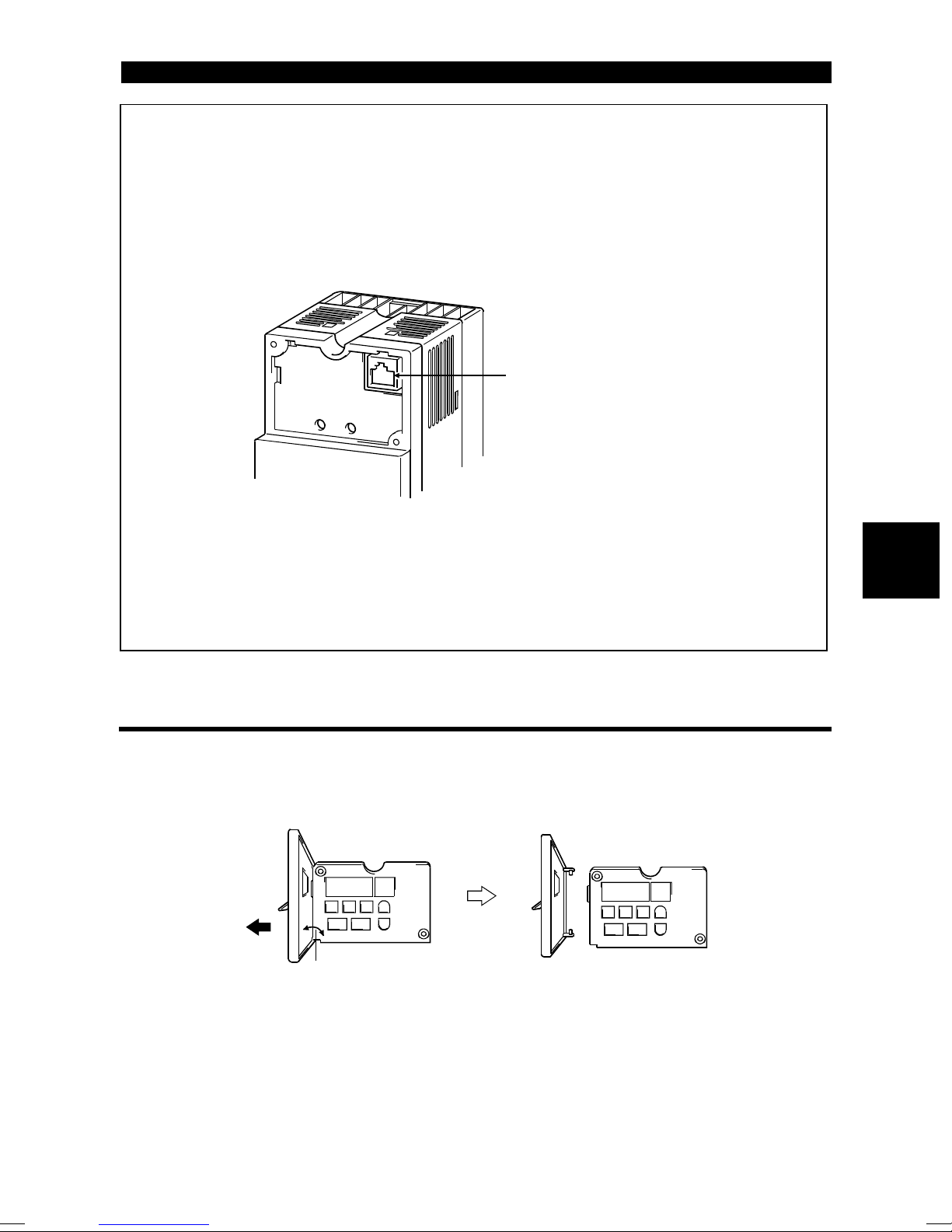
z Using the connection cable for operation
1) Fit the rear cover option FR-E5P to the back surface of the optional control
panel.
2) Securely plug one end of the connection cable into the PU connector of the
inverter and the other end into the adaptor of the FR-E5P option to connect it
to the control panel. (For the connection cable of the FR-E5P, refer to page
28.)
PU connector
(RS-485 cable specifications
z Mounting the control panel on an enclosure
When you open the control panel front cover, the screw mounting guides for
fixing the control panel to an enclosure appear on the top left and bottom right.
Fit the rear cover of the FR-E5P option, drill holes in the control panel mounting
guides, and securely mount the control panel on the enclosure with screws.
1.3.6 Removal of the control panel (FR-PA02-02) front cover
1) Open the control panel front cover to 90 degrees.
2) Pull out the control panel front cover to the left to remove it.
90 degrees
1
10
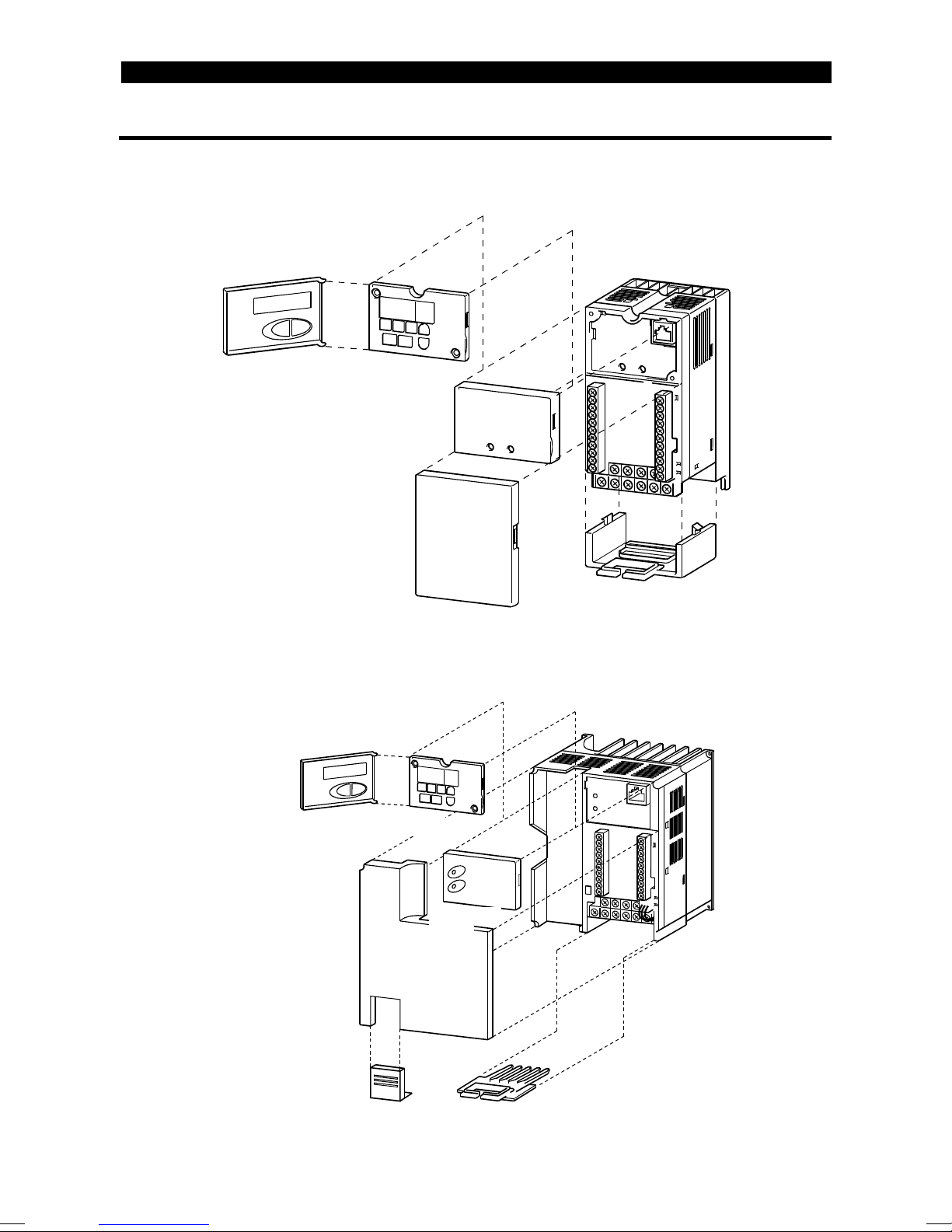
1.3.7 Exploded view
W
f
z FR-E520-0.1K to 7.5K-NA
z FR-E510W-0.1K to 0.75K-NA
OUTLINE
Control panel (FR-PA02 )
Accessory cov er
z FR-E540-0.4K to 7.5K-NA
Control panel (FR-PA02-02)
-02
Wiring cover
Front cover
Front cover
iring port cover
or option
Accessory
cover
Wiring cover
11

C H A P T E R 2
CHAPTER 2
INSTALLATION AND
INSTALLATIONAND
WIRINNG
WIRING
This chapter gives information on the basic "installation and
wiring" for use of this product.
Always read the instructions in this chapter before using the
equipment.
2.1 Installation ....................................................................12
2.2 Wiring ...........................................................................14
2.3 Other Wiring ................................................................. 35
Chapter 1
Chapter 2
Chapter 3
Chapter 4
Chapter 5
Chapter 6
2.1 Installation
>
INSTALLATION AND WIRING
2 INSTALLATION AND WIRING
2.1 Installation
2.1.1 Instructions for installation
For the FR-E520-0.1K to 0.75K-NA and FR-E510W-0.1K to 0.4K-NA, install the
inverter with the accessory cover or control panel (FR-PA02-
02
) front cover open.
<For the accessory cover> <For the control panel (FR-PA02 )
-02
1) Handle the unit carefully.
The inverter uses plastic parts. Handle it gently to protect it from damage.
Also, hold the unit with even strength and do not apply too much strength to the front
cover alone.
2) Install the inverter in a place where it is not affected by vibration easily (5.9m/s
{0.6G} maximum).
Note the vibration of a cart, press, etc.
2
3) Note on ambient temperature.
The inverter life is under great influence of ambient temperature. In the place of
installation, the ambient temperature must be within the permissible range -10°C to
+50°C (14°F to 122°F). Check that the ambient temperature is within that range in
the positions shown in figure 3).
4) Install the inverter on a non-combustible surface.
The inverter will be very hot (maximum about 150°C (302°F)). Install it on a noncombustible surface (e.g. metal). Also leave sufficient clearances around the
inverter.
5) Avoid high temperatures and high humidity.
Avoid direct sunlight and places of high temperature and high humidity.
6) Avoid places where the inverter is exposed to oil mist, flammable gases, fluff, dust,
dirt etc.
Install the inverter in a clean place or inside a "totally enclosed" panel which does
not accept any suspended matter.
12
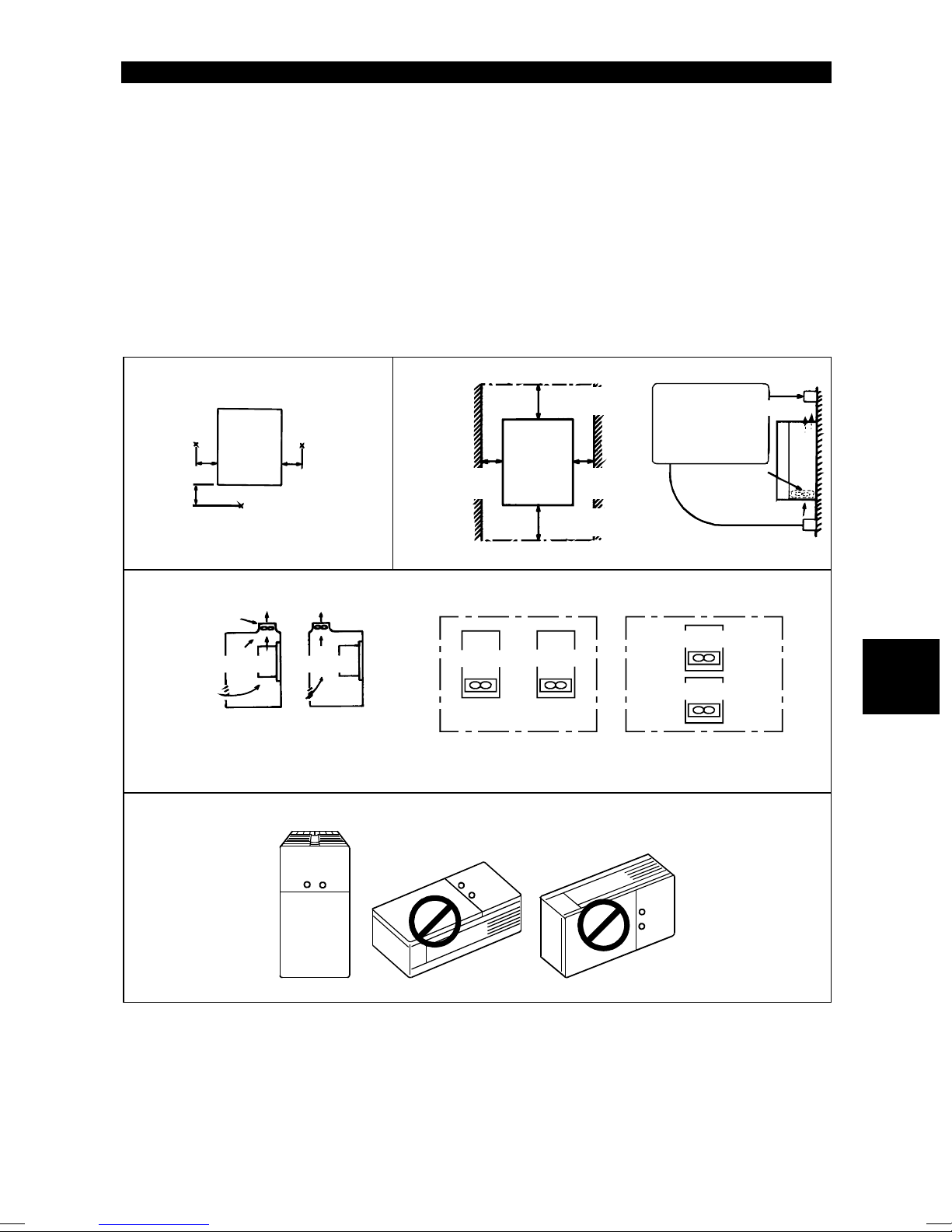
INSTALLATION AND WIRING
V
f
g
7) Note the cooling method when the inverter is installed in an enclosure.
When two or more inverters are installed or a ventilation fan is mounted in an
enclosure, the inverters and ventilation fan must be installed in proper positions with
extreme care taken to keep the ambient temperatures of the inverters with the
permissible values. If they are installed in improper positions, the ambient
temperatures of the inverters will rise and ventilation effect will be reduced.
8) Install the inverter on an installation surface securely and vertically with screws or
bolts.
3) Note on ambient
temperatures
Measurement
position
5cm
(1.97inch)
5cm
(1.97inch)
FR-E500
Measurement position
5cm
(1.97inch)
7) For installation in an enclosure
entilation
an
Inverter
(Correct example) (Incorrect example)
Position of Ventilation Fan
Inverter
8) Vertical mounting
4) Clearances around the inverter
1cm (0.39inch)
or more*
*5cm (1.97inch) or more for 5.5K and 7.5K
Inverter
Built-in coolin
(Correct example)
When more than one inverter is contained
10cm (3.94inch )
or more
FR-E500
10cm (3.94inch )
or more
Inverter
fan
1cm (0.39inch)
or more*
Leave sufficient
clearances above
and under the
inverter to ensure
adequate ventilation.
(Incorrect example)
Cooling fan
built in the
inverter
Inverter
Inverter
Cooling air
2
13
2.2 Wiring
2.2 Wiring
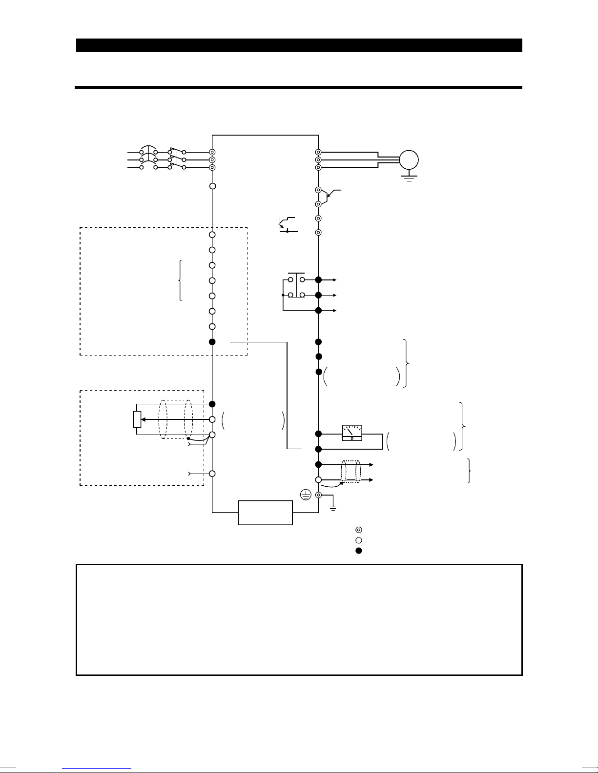
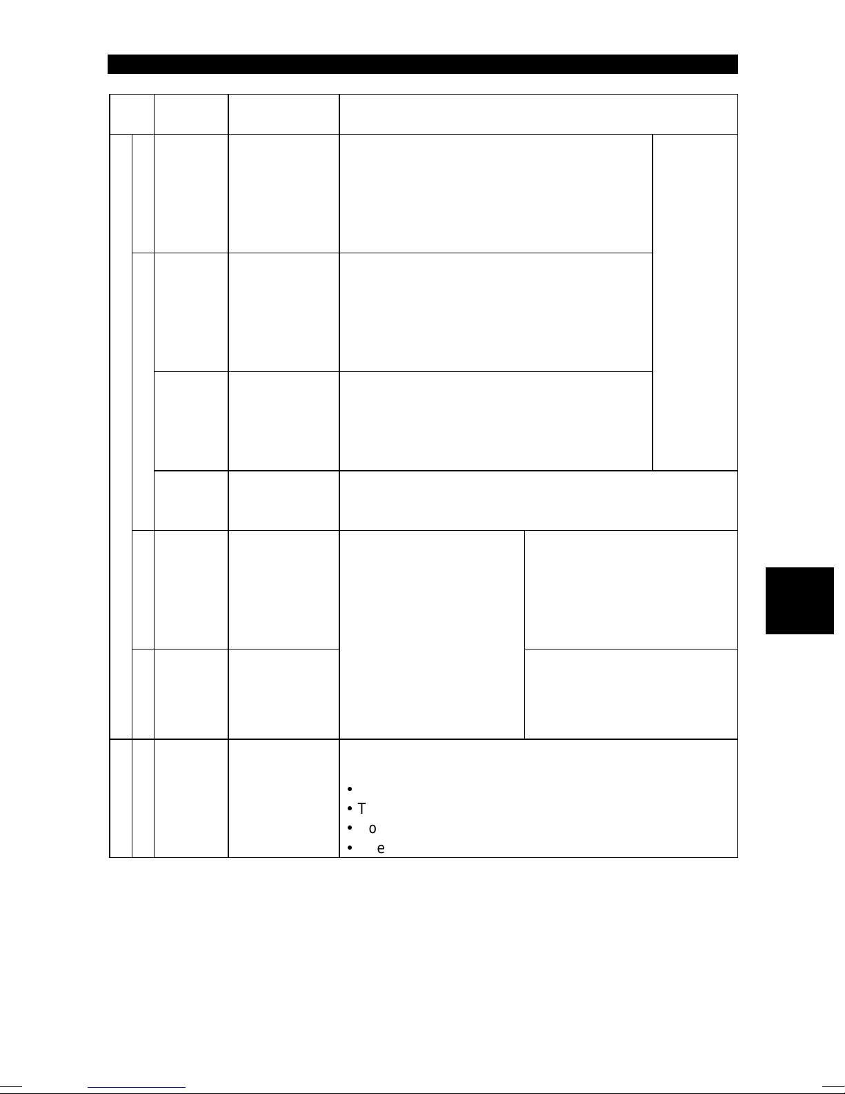
2.2.1 Terminal connection diagram
z 3-phase 200V power input
z 3-phase 400V power input
INSTALLATION AND WIRING
NFB
3-phase AC
power supply
24VDC power output and
external transistor common
Forward rotation start
Reverse rotation start
Multi-speed se lection
Contact input common
Control input signals
(no voltage input allowed)
Frequency setting signals (analog)
(Note 1)
Frequency
setting
potentiometer
1/2W1kΩ
3
1
Current input(-)
4 to 20mADC(+)
MC
Middle
Output stop
Reset
2
R(L
S(L
T(L3)
PC
Note 5
STF
STR
RH
High
RM
RL
Low
MRS
RES
SD
10(+5V)
2
5(Common)
Note 4
4(4 to 20mADC)
)
1
)
2
Note 4
0 to 5VDC
0 to 10VDC
Selected
P1
(+)P
PR
(-)N
Note 2
RUN
FU
SE
Note 3
FM
SD
Note 3
AM
U
V
W
Jumper
Remove this jumper when
using the optional power-factor
improving DC reactor.
Brake resistor connection
A
B
C
5
Alarm
detection
Running
Frequency detection
Open collector
output common)
(e.g. frequency meter)
Meter
-
+
Motor
IM
Ground
Open
collector outputs
Moving-coil type
1mA full-scale
(+)
Analog signal output
(0 to 10VDC)
(−)
For 200V and
100V class
inverters
For 400V
class inverter
Note:1. If the potentiometer is to be operated often, use a 2W1kΩ potentiometer.
2. 0.1K and 0.2K do not contain a transistor.
3. Terminals SD and SE are isolated.
4. Terminals SD and 5 are common terminals. Do not earth them to the
ground. Terminals SD and 5 are not isolated. (Those of the 400V class are
isolated.)
5. When terminals PC-SD are used as a 24VDC power supply, be careful not
to short these terminals. If they are shorted, the inverter will be damaged.
PU connector
(RS-485)
Ground
Main circuit terminal
Control circuit input terminal
Control circuit output terminal
14
z Single-phase 100V power input
INSTALLATION AND WIRING
NFB
Power supply
MC
R (L
S (L
)
1
)
2
U
V
W
Motor
IM
Ground
Note:1. To ensure safety, connect the power input to the inverter via a magnetic
contactor and earth leakage circuit breaker or no-fuse breaker, and use the
magnetic contactor to switch power on-off.
2. The output is three-phase 200V.
(1)
Description of the main circuit terminals
Symbol Terminal Name Description
R, S, T
(L
, L2, L3)
1
AC power input
(Note)
U, V, W Inverter output Connect a three-phase squirrel-cage motor.
P (+), PR
P (+), N (−)
Brake resistor
connection
Brake unit
connection
Power factor
P (+), P1
improving DC
reactor connection
Connect to the commercial power supply. Keep these
terminals unconnected when using the high power factor
converter.
Connect the optional brake resistor across terminals P-PR
(+ - PR) (not for 0.1K and 0.2K).
Connect the optional brake unit or high power factor
converter.
Disconnect the jumper from terminals P-P1 (+ - P1) and
connect the optional power factor improving DC reactor.
2
Ground For grounding the inverter chassis. Must be earthed.
Note: R, S (L1, L2) terminals for single-phase power input.
15

(2)
Description of the control circuit terminals
INSTALLATION AND WIRING
Type Symbol
STF
STR
RH, RM,RLMulti-speed
MRS Output stop
Input signals
Analog
RES Reset
SD
Contacts, e.g. start (STF), stop (STOP) etc
PC
10
2
4
Frequency setting
5
Terminal
Name
Forward
rotation start
Reverse
rotation start
selection
Contact input
common
(sink*)
Power output
and external
transistor
common
Contact input
common
(source*)
Frequency
setting power
supply
Frequency
setting
(voltage)
Frequency
setting
(current)
Frequency
setting input
common
Description
When the ST F
Turn on the STF signal to start forward
rotation and turn it off t o st op.
Turn on the STR signal to start reverse
rotation and turn it off t o st op.
Combine the RH, RM and RL signals
as appropriate to select multiple
speeds.
Turn on the MRS signal (20ms or
longer) to stop the inverter output.
Used to shut off the inverter output to
bring the motor to a stop by the
electromagnetic brake.
Used to reset the protective circuit activated. Turn on the
RES signal for more than 0.1 second then t urn it off.
Common to the contact input terminals and terminal FM.
Common output terminal for 24VDC 0.1A power output
(PC terminal).
When transist or output (open collector output), such as a
programmable controller (PC), is connected, connect the
external power supply common for transistor output t o this
terminal to prevent a fault caused by leakage current. T his
terminal can be used as a 24VDC, 0.1A power output.
5VDC, permissible load current 10mA
By entering 0 to 5VDC (0 to 10VDC), the maximum output
frequency is reached at 5V (or 10V) and I/O are
proportional. Use Pr. 73 to switch between input 0 to
5VDC (factory setting) and 0 to 10VDC. Input resistance
10kΩ. Maximum perm issible voltage 20V.
By entering 4 to 20mADC, the m aximum out put frequency
is reached at 20mA and I/O are proportional. This input
signal is valid only when the AU signal is on. Input
resistance 250Ω. Maximum permissible current 30mA.
Common to the frequency setting signals (terminal 2, 1 or 4).
Do not connect to the earth.
and STR signals
are turned on
simultaneously,
the stop
command is
given.
Input terminal
function choices
(Pr. 180 to
Pr. 183) change
terminal functions.
Note: Assign the AU signal to any of the terminals using the input terminal function
selection (Pr. 180 to Pr. 183).
* Used as a contact input signal common terminal for the 400V class by switching
between sink logic and source logic. (Refer to page 24).
16
INSTALLATION AND WIRING
Type Symbol
A, B, C Alarm output
Contact
RUN
FU
Open collector
Output signals
SE
FM
(200V
and
100V
Pulse
class
inverters)
AM
(400V
class
Analog
only)
Terminal
Name
Inverter
running
Frequency
detection
Open collector
output
common
For meter
Analog signal
output
Description
Contact output indicating that the out put has
been stopped by the inverter protective
function activated. 230VAC 0.3A, 30VDC
0.3A. Alarm: discontinuity across B-C
(continuity across A-C), normal: continuity
across B-C (discontinuity across A-C).
Switched low when the inverter output
frequency is equal to or higher than the
starting frequency (factory set to 0.5Hz,
variable). Switched high during stop or DC
dynamic brake operation (*1).
Permissible load 24VDC 0.1A.
Switched low when the output frequency has
reached or exceeded the detection frequency
set as appropriate. Switched high when below
the detection frequency (*1).
Permissible load 24VDC 0.1A
Common to the RUN and FU terminals.
Factory setting of output item:
One selected from out put
frequency, motor current
and output voltage is
output (*2). The output
signal is proportional to
the magnitude of each
monitoring item.
Frequency
Permissible load current 1mA
1440 pulses/second at 60Hz
Factory setting of output item:
Frequency
Output signal 0 to 10 VDC
Permissible load current 1mA
Output
terminal
function
choices
(Pr. 190 to
Pr. 192)
change
terminal
functions.
2
RS-485
Communication
PU connector
*1: Low indicates that the open collector output transistor is on (conducts). High
indicates that the transistor is off (does not conduct).
*2: Not output during inverter resetting.
With the control panel connector, communication can be
made using the RS-485 protocol.
y
Conforming Standard : EIA Standard RS-485
y
Transmission format : Multi-drop link
y
Communication speed : Maximum 19200 baud rate
y
Overall length : 500m (1640.40 feet)
17
 Loading...