

Page 1
Page 2
Thank you for choosing the Mitsubishi Transistorized inverter.
This instruction manual gives handling information and precautions for use of this
equipment.
Incorrect handling might cause an unexpected fault. Before using the inverter, please
read this manual carefully to use the equipment to its optimum.
Please forward this manual to the end user.
This instruction manual uses the International System of Units (SI). The measuring
units in the yard and pound system are indicated in parentheses as reference values.
This section is specifically about safety matters
Do not attempt to install, operate, maintain or inspect the inverter until you have read
through this instruction manual and appended documents carefully and can use the
equipment correctly.
Do not use the inverter until you have a full knowledge of the equipment, safety
information and instructions.
In this manual, the safety instruction levels are classified into "WARNING" and
"CAUTION".
Assumes that incorrect handling may cause hazardous
WARNING
CAUTION
Note that even the CAUTION level may lead to a serious consequence according to
conditions. Please follow the instructions of both levels because they are important
to personnel safety.
conditions, resulting in death or severe injury.
Assumes that incorrect handling may cause hazardous
conditions, resulting in medium or slight injury, or may
cause physical damage only.
A - 1
Page 3
SAFETY INSTRUCTIONS
1. Electric Shock Prevention
WARNING
!
While power is on or when the inverter is running, do not open the front cover.
You may get an electric shock.
!
Do not run the inverter with the front cover removed. Otherwise, you may access
the exposed high-voltage terminals or the charging part of the circuitry and get
an electric shock.
!
If power is off, do not remove the front cover except for wiring or periodic
inspection. You may access the charged inverter circuits and get an electric
shock.
!
Before starting wiring or inspection, switch power off, wait for more than 10
minutes, and check for residual voltage with a meter (refer to chapter 2 for
further details) etc.
!
Earth the inverter.
!
Any person who is involved in the wiring or inspection of this equipment should
be fully competent to do the work.
!
Always install the inverter before wiring. Otherwise, you may get an electric
shock or be injured.
!
Operate the switches and potentiometers with dry hands to prevent an electric
shock.
!
Do not subject the cables to scratches, excessive stress, heavy loads or
pinching. Otherwise, you may get an electric shock.
!
Do not change the cooling fan while power is on.
It is dangerous to change the cooling fan while power is on.
2. Fire Prevention
CAUTION
!
Mount the inverter and brake resistor on an incombustible surface. Installing the
inverter directly on or near a combustible surface could lead to a fire.
!
If the inverter has become faulty, switch off the inverter power. A continuous
flow of large current could cause a fire.
!
When a brake resistor is used, use an alarm signal to switch power off.
Otherwise, the brake resistor will overheat abnormally due a brake transistor or
other fault, resulting in a fire.
!
Do not connect a resistor directly to the DC terminals P(+), N(−). This could
cause a fire.
A - 2
Page 4

3. Injury Prevention
CAUTION
!
Apply only the voltage specified in the instruction manual to each terminal to
prevent damage etc.
!
Ensure that the cables are connected to the correct terminals. Otherwise,
damage etc. may occur.
!
Always make sure that polarity is correct to prevent damage etc.
!
While power is on and for some time after power-off, do not touch the inverter or
brake resistor as they are hot and you may get burnt.
4. Additional instructions
Also note the following points to prevent an accidental failure, injury, electric shock, etc.
(1)
Transportation and installation
CAUTION
!
When carrying products, use correct lifting gear to prevent injury.
!
Do not stack the inverter boxes higher than the number recommended.
!
Ensure that installation position and material can withstand the weight of the
inverter. Install according to the information in the Instruction Manual.
!
Do not operate if the inverter is damaged or has parts missing.
!
Do not hold the inverter by the front cover or operation panel; it may fall off.
!
Do not stand or rest heavy objects on the inverter.
!
Check the inverter mounting orientation is correct.
!
Prevent screws, wire fragments or other conductive bodies or oil or other
flammable substance from entering the inverter.
!
Do not drop the inverter, or subject it to impact.
!
Use the inverter under the following environmental conditions:
Ambient
temperature
Ambient humidit y 90%RH or less (non-condensing)
Storage
temperature
Ambience
Environment
Altitude, vibration
*Temperatures applicable for a short time, e.g. in transit.
Constant torque : -10°C to +50°C (14°F to 122 °F)
(non-freezing)
-20°C to +65°C * (-4°F to 149 °F)
Indoors (free from corrosive gas, flammable gas, oil mist, dust
and dirt)
Maximum 1000m (3280.80 feet) above sea level for standard
operation. After that derate by 3% for every extra 500m
(1640.40 feet) up to 2500m (8202.00 feet) (91%).
5.9 m/s
2
or less (conforming to JIS C 0911)
A - 3
Page 5
(2)
Wiring
CAUTION
!
Do not fit capacitive equipment such as a power factor correction capacitor,
radio noise filter or surge suppressor to the output of the inverter.
!
The connection orientation of the output cables U, V, W to the motor will affect
the direction of rotation of the motor.
(3)
Trial run
CAUTION
!
Check all parameters, and ensure that the machine will not be damaged by a
sudden start-up.
(4)
Operation
WARNING
!
When you have chosen the retry function, stay away from the equipment as it
will restart suddenly after an alarm stop.
!
The [STOP] key is valid only when the appropriate function setting has been
made. Prepare an emergency stop switch separately.
!
Make sure that the start signal is off before resetting the inverter alarm. A failure
to do so may restart the motor suddenly.
!
The load used should be a three-phase induction motor only. Connection of any
other electrical equipment to the inverter output may damage the equipment.
!
Do not modify the equipment.
CAUTION
!
The electronic overcurrent protection does not guarantee protection of the
motor from overheating.
!
Do not use a magnetic contactor on the inverter input for frequent
starting/stopping of the inverter.
!
Use a noise filter to reduce the effect of electromagnetic interference. Otherwise
nearby electronic equipment may be affected.
!
Take measures to suppress harmonics. Otherwise power harmonics from the
inverter may heat/damage the power capacitor and generator.
A - 4
Page 6

CAUTION
!
When a 400V class motor is inverter-driven, it should be insulation-enhanced or
surge voltages suppressed. Surge voltages attributale to the wiring constants
may occur at the motor terminals, deteriorating the insulation of the motor.
!
When parameter clear or all clear is performed, each parameter returns to the
factory setting. Re-set the required parameters before starting operation.
!
The inverter can be easily set for high-speed operation. Before changing its
setting, fully examine the performances of the motor and machine.
!
In addition to the inverter's holding function, install a holding device to ensure
safety.
!
Before running an inverter which had been stored for a long period, always
perform inspection and test operation.
(5)
Emergency stop
CAUTION
!
Provide a safety backup such as an emergency brake which will prevent the
machine and equipment from hazardous conditions if the inverter fails.
(6)
Maintenance, inspection and parts replacement
CAUTION
!
Do not carry out a megger (insulation resistance) test on the control circuit of
the inverter.
(7)
Disposing of the inverter
CAUTION
!
Treat as industrial waste.
(8) General
Many of the diagrams and drawings in this instruction manual show the inverter
without a cover, or partially open. Never operate the inverter like this. Always
replace the cover and follow this instruction manual when operating the inverter.
instructions
A - 5
Page 7

CONTENTS
1 OUTLINE 1
1.1 Pre-Operation Information ..........................................................................................1
1.1.1 Precautions for operation.....................................................................................1
1.2 Basic Configuration.....................................................................................................3
1.2.1 Basic configuration...............................................................................................3
1.3 Structure .....................................................................................................................4
1.3.1 Appearance and structure....................................................................................4
1.3.2 Removal and reinstallation of the front cover.......................................................5
1.3.3 Removal and reinstallation of the wiring cover.....................................................7
1.3.4 Removal and reinstallation of the accessory cover..............................................8
1.3.5 Reinstallation and removal of the control panel....................................................9
1.3.6 Removal of the control panel (FR-PA02-
1.3.7 Exploded view....................................................................................................11
) front cover .....................................10
02
2 INSTALLATION AND WIRING 12
Contents
2.1 Installation.................................................................................................................12
2.1.1 Instructions for installation..................................................................................12
2.2 Wiring........................................................................................................................14
2.2.1 Terminal connection diagram.............................................................................14
2.2.2 Wiring of the main circuit....................................................................................18
2.2.3 Wiring of the control circuit.................................................................................22
2.2.4 Connection to the PU connector ........................................................................27
2.2.5 Connection of stand-alone option units..............................................................30
2.2.6 Design information .............................................................................................33
2.3 Other Wiring..............................................................................................................34
2.3.1 Power supply harmonics....................................................................................34
2.3.2 Inverter-generated noise and reduction techniques...........................................35
2.3.3 Leakage currents and countermeasures............................................................39
2.3.4 Inverter-driven 400V class motor........................................................................40
2.3.5 Peripheral devices ..............................................................................................41
2.3.6 Instructions for compliance with U.S and Canadian Electrical Codes................45
2.3.7 Instructions for compliance with the European standards..................................46
I
Page 8

3 OPERATION/CONTROL 48
3.1 Pre-Operation Information ........................................................................................48
3.1.1 Types of operation modes..................................................................................48
3.1.2 Power on............................................................................................................50
3.2 About the Control Panel............................................................................................51
3.2.1 Names and functions of the control panel (FR-PA02-
3.2.2 Control panel mode is changed by pressing the
MODE
)....................................51
02
key.................................52
3.2.3 Monitoring...........................................................................................................52
3.2.4 Frequency setting...............................................................................................53
3.2.5 Parameter setting method..................................................................................53
3.2.6 Operation mode..................................................................................................55
3.2.7 Help mode..........................................................................................................55
3.3 Operation..................................................................................................................58
3.3.1 Pre-operation checks .........................................................................................58
3.3.2 External operation mode (Operation using the external
frequency setting potentiometer and external start signal).................................59
3.3.3 PU operation mode (Operation using the control panel)....................................60
3.3.4 Combined operation mode 1
(Operation using both external start signal and control panel)...........................61
3.3.5 Combined operation mode 2..............................................................................62
4 PARAMETERS 63
4.1 Parameter List...........................................................................................................63
4.1.1 Parameter list.....................................................................................................63
4.1.2 List of parameters classified by purpose of use.................................................69
4.1.3 Parameters recommended to be set by the user...............................................71
4.2 Parameter Function Details ......................................................................................72
4.2.1 Torque boost (Pr. 0, Pr. 46)................................................................................72
4.2.2 Output frequency range (Pr. 1, Pr. 2, Pr. 18)......................................................73
4.2.3 Base frequency, base frequency voltage (Pr. 3, Pr. 19, Pr. 47).........................74
4.2.4 Multi-speed operation (Pr. 4, Pr. 5, Pr. 6, Pr. 24 to Pr. 27, Pr. 232 to Pr. 239) .75
4.2.5 Acceleration/deceleration time (Pr. 7, Pr. 8, Pr. 20, Pr. 21, Pr. 44, Pr. 45) .......76
4.2.6 Electronic overcurrent protection (Pr. 9, Pr. 48).................................................78
4.2.7 DC injection brake (Pr. 10 to Pr. 12)...................................................................79
II
Page 9

4.2.8 Starting frequency (Pr. 13).................................................................................80
4.2.9 Load pattern selection (Pr. 14)...........................................................................81
4.2.10 Jog operation (Pr. 15, Pr. 16)...........................................................................82
4.2.11 Stall prevention (Pr. 22, Pr. 23, Pr. 66).............................................................83
4.2.12 Acceleration/deceleration pattern (Pr. 29)........................................................85
4.2.13 Regenerative brake duty (Pr. 30, Pr. 70)..........................................................86
4.2.14 Frequency jump (Pr. 31 to Pr. 36)....................................................................87
4.2.15 Speed display (Pr. 37)......................................................................................88
4.2.16 Frequency at 5V (10V) input (Pr. 38)................................................................89
4.2.17 Frequency at 20mA input (Pr. 39)....................................................................89
4.2.18 Up-to-frequency sensitivity (Pr. 41)..................................................................90
4.2.19 Output frequency detection (Pr. 42, Pr. 43)......................................................90
4.2.20 Monitor display (Pr. 52, Pr. 54, Pr. 158)...........................................................92
4.2.21 Monitoring reference (Pr. 55, Pr. 56)................................................................94
4.2.22 Automatic restart after instantaneous power failure (Pr. 57, Pr. 58).................95
4.2.23 Remote setting function selection (Pr. 59)........................................................97
4.2.24 Shortest acceleration/deceleration mode (Pr. 60 to Pr. 63)..............................99
4.2.25 Retry function (Pr. 65, Pr. 67 to Pr. 69)..........................................................101
Contents
4.2.26 Applied motor (Pr. 71)....................................................................................103
4.2.27 PWM carrier frequency (Pr. 72, Pr. 240)........................................................104
4.2.28 Voltage input (Pr. 73) .....................................................................................105
4.2.29 Input filter time constant (Pr. 74)....................................................................106
4.2.30 Reset selection/disconnected PU detection/PU stop selection (Pr. 75).........106
4.2.31 Parameter write inhibit selection (Pr. 77)........................................................108
4.2.32 Reverse rotation prevention selection (Pr. 78)...............................................109
4.2.33 Operation mode selection (Pr. 79) .................................................................110
4.2.34 General-purpose magnetic flux v ector contr ol selection ( Pr. 80).........................113
4.2.35 Offline auto tuning function (Pr. 82 to Pr. 84, Pr. 90, Pr. 96)..........................115
4.2.36 Computer link operation (Pr. 117 to Pr. 124, Pr. 342)....................................121
4.2.37 PID control (Pr. 128 to Pr. 134)......................................................................134
4.2.38 Output current detection function (Pr. 150, Pr.151)........................................142
4.2.39 Zero current detection (Pr. 152, Pr.153).........................................................143
4.2.40 Stall prevention function and current limit function (Pr. 156)..........................144
4.2.41 User group selection (Pr. 160, Pr. 173 to Pr. 176) .........................................146
4.2.42 Actual operation hour meter clear (Pr. 171)...................................................148
III
Page 10

4.2.43 Input terminal function selection (Pr. 180 to Pr. 183).....................................148
4.2.44 Output terminal function selection (Pr. 190 to Pr. 192)...................................150
4.2.45 Cooling fan operation selection (Pr. 244).......................................................151
4.2.46 Slip compensation (Pr. 245 to Pr. 247) ..........................................................152
4.2.47 Ground fault detection at start (Pr. 249)
(400V class does not have this function)........................................................153
4.2.48 Stop selection (Pr. 250)..................................................................................154
4.2.49 Output phase failure protection selection (Pr. 251)........................................155
4.2.50 Meter (frequency meter) calibration (Pr. 900) (200V class, 100V class).......156
4.2.51 Meter (frequency meter) calibration (Pr. 901) (400V class)............................158
4.2.52 Biases and gains of the frequency setting voltage (current)
(Pr. 902 to Pr. 905)...........................................................................................160
5 PROTECTIVE FUNCTIONS 166
5.1 Errors (Alarms)........................................................................................................166
5.1.1 Error (alarm) definitions....................................................................................166
5.1.2 To know the operating status at the occurrence of alarm.................................174
5.1.3 Correspondence between digital and actual characters...................................174
5.1.4 Resetting the inverter.......................................................................................174
5.2 Troubleshooting......................................................................................................175
5.2.1 Motor remains stopped.....................................................................................175
5.2.2 Motor rotates in opposite direction...................................................................175
5.2.3 Speed greatly differs from the setting...............................................................176
5.2.4 Acceleration/deceleration is not smooth...........................................................176
5.2.5 Motor current is large........................................................................................ 176
5.2.6 Speed does not increase..................................................................................176
5.2.7 Speed varies during operation..........................................................................176
5.2.8 Operation mode is not changed properly.........................................................177
5.2.9 Control panel display is not operating ..............................................................177
5.2.10 POWER lamp is not lit....................................................................................177
5.2.11 Parameter write cannot be performed............................................................177
5.3 Precautions for Maintenance and Inspection..........................................................178
5.3.1 Precautions for maintenance and inspection ...................................................178
5.3.2 Check items......................................................................................................178
5.3.3 Periodic inspection...........................................................................................178
IV
Page 11

5.3.4 Insulation resistance test using megger...........................................................179
5.3.5 Pressure test....................................................................................................179
5.3.6 Daily and Periodic Inspection...........................................................................180
5.3.7 Replacement of parts.......................................................................................183
5.3.8 Measurement of main circuit voltages, currents and powers............................188
6 SPECIFICATIONS 191
6.1 Standard Specifications..........................................................................................191
6.1.1 Model specifications.........................................................................................191
6.1.2 Common specifications....................................................................................194
6.1.3 Outline drawings...............................................................................................196
APPENDIX 202
Appendix 1 Data Code List...........................................................................................202
Contents
V
Page 12

C H A P T E R 1
CHAPTER 1
O U T L I N E
OUTLINE
This chapter gives information on the basic "outline" of this
product.
Always read the instructions before using the equipment.
1.1 Pre-Operation Information ..........................................1
1.2 Basic Configuration.....................................................3
1.3 Structure.....................................................................4
<Abbreviations>
!
PU
Control panel and parameter
unit (FR-PU04)
!
Inverter
Mitsubishi transistorized inverter
FR-E500 series
!
Pr.
Parameter number
Chapter 1
Chapter 2
Chapter 3
Chapter 4
Chapter 5
Chapter 6
Page 13
1.1 Pre-Operation Information
OUTLINE
1 OUTLINE
1.1 Pre-Operation Information
1.1.1 Precautions for operation
This manual is written for the FR-E500 series transistorized inverters.
Incorrect handling may cause the inverter to operate incorrectly, causing its life to be
reduced considerably, or at the worst, the inverter to be damaged. Handle the inverter
properly in accordance with the information in each section as well as the precautions
and instructions of this manual to use it correctly.
For handling information on the parameter unit (FR-PU04), stand-alone options, etc.,
refer to the corresponding manuals.
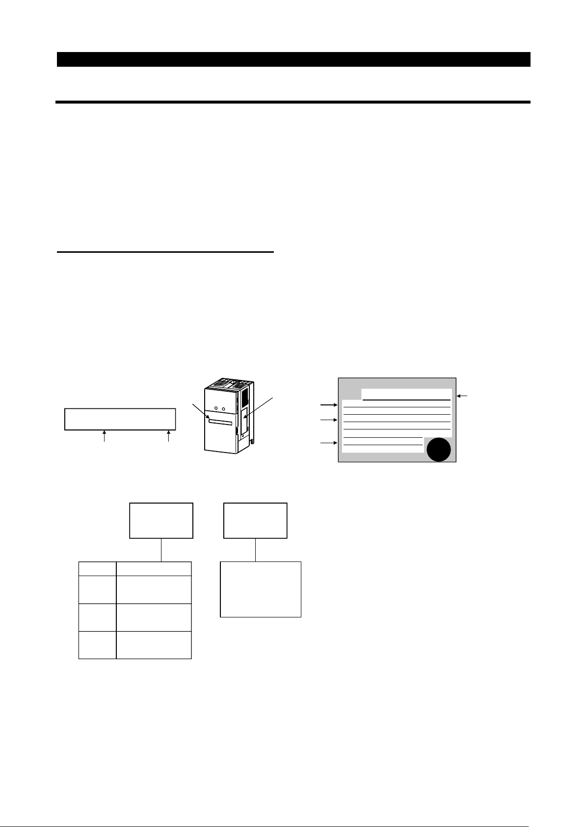
(1)
Unpacking and product check
Unpack the inverter and check the capacity plate on the front cover and the rating plate
on the inverter side face to ensure that the product agrees with your order and the
inverter is intact.
1) Inverter type
Capacity plate
FR-E520-0.1K-NA/
Inverter type
"
Inverter type
FR -
Symbol Voltage Class
E520
E540
E510W
E520
Three-phase
200V class
Three-phase
400V class
Single-phase
100V class
Capacity plate
Serial number
Rating plate
MITSUBISHI
Rating plate
Input rating
Output rating
Serial number
MODEL
FR-E520-0.1K-NA
INPUT :
XXXXX
OUTPUT :
XXXXX
SERIAL :
-0.1K - NA
Represents the
inverter capacity
".
"kW
INVERTER
Inverter type
PASSED
2) Accessory
Instruction manual
If you have found any discrepancy, damage, etc., please contact your sales
representative.
1
Page 14

OUTLINE
(2)
Preparation of instruments and parts requi r ed for operation
Instruments and parts to be prepared depend on how the inverter is operated. Prepare
equipment and parts as necessary. (Refer to page 48.)
(3)
Installation
To operate the inverter with high performance for a long time, install the inverter in a
proper place, in the correct direction, with proper clearances. (Refer to page 12.)
(4)
Wiring
Connect the power supply, motor and operation signals (control signals) to the terminal
block. Note that incorrect connection may damage the inverter and peripheral devices.
(See page 14.)
1
2
Page 15
1.2 Basic Configuration
A
(
)
OUTLINE
1.2 Basic Configuration
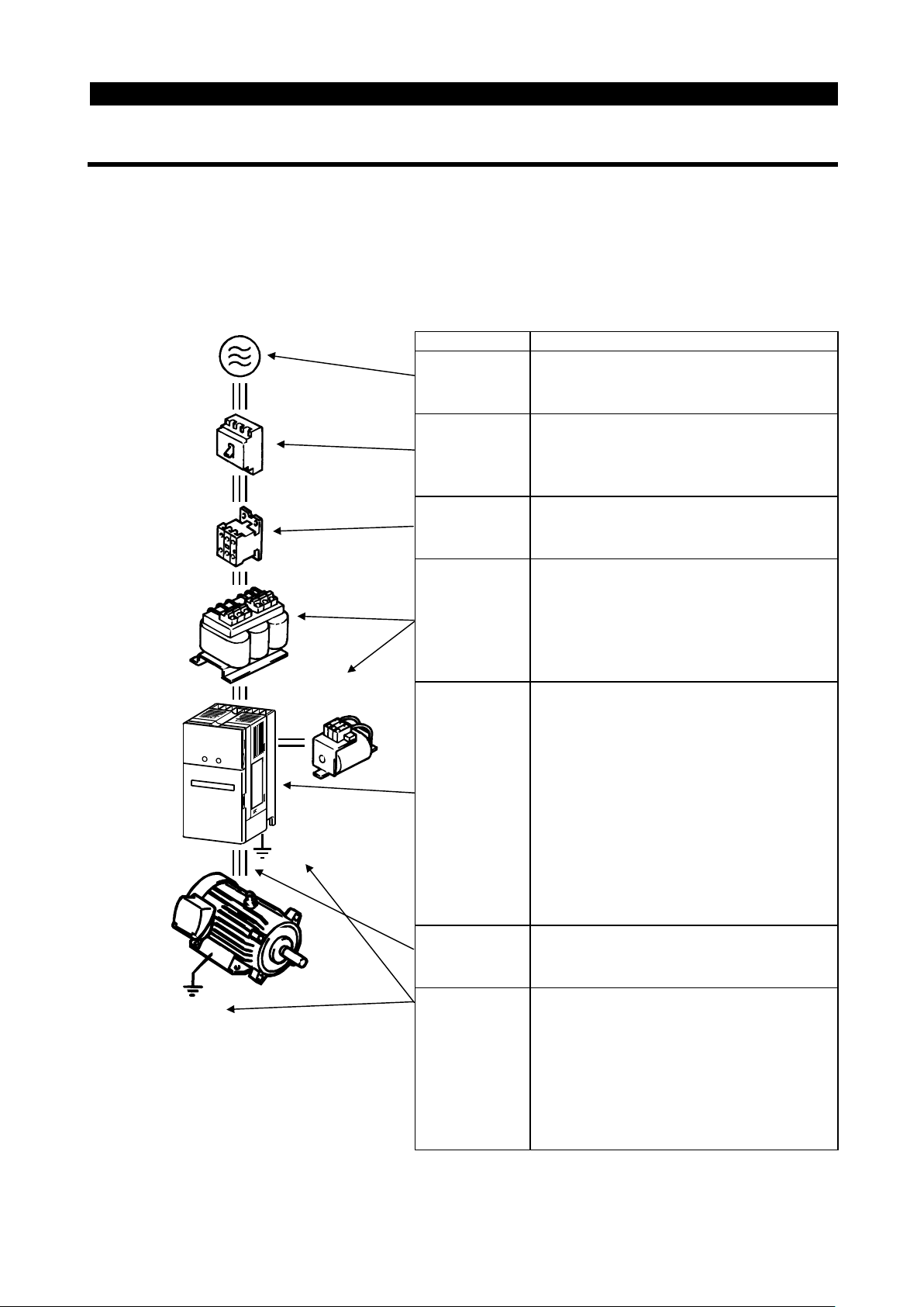
1.2.1 Basic configuration
The following devices are required to operate the inverter. Proper peripheral devices
must be selected and correct connections made to ensure proper operation. Incorrect
system configuration and connections can cause the inverter to operate improperly, its
life to be reduced considerably, and in the worst case, the inverter to be damaged.
Please handle the inverter properly in accordance with the information in each section
as well as the precautions and instructions of this manual. (For connections of the
peripheral devices, refer to the corresponding manuals.)
Name Description
Use the power supply within the
permissible power supply specifications
of the inverter. (Refer to page 191.)
The breaker should be selected with
care since a large inrush current flows
in the inverter at power on. (Refer to
page 41.)
Do not use this magnetic contactor to
start or stop the inverter. It might reduce
the inverter life. (Refer to page 41.)
The reactors must be used when the
power factor is to be improved or the
inverter is installed near a large power
supply system (1000KVA or more and
wiring distance within 10m (32.81 feet)).
Make selection carefully.
•
The inverter life is influenced by
ambient temperature. The ambient
temperature should be as low as
possible within the permissible range.
This must be noted especially when
the inverter is installed in an enclosure.
(Refer to page 12.)
•
Wrong wiring might lead to inverter
damage. The control signal lines should
be kept away from the main circuit to
protect them from noise. (Refer to page
14.)
Do not connect a power capacitor,
surge suppressor or radio noise
filter to the output side.
To prevent an electric shock, always
ground the motor and inverter.
The ground wiring from the power line
of the inverter as an induction noise
reduction technique is recommended to
be run by returning it to the ground
terminal of the inverter. (Refer to page
38.)
(NFB)
(ELB)
C reactor
FR-BAL
or
(MC)
Ground
Power
supply
Earth leakage
circuit breaker
or no-fuse
breaker
Magnetic
contactor
Reactors
DC reactor
(FR-BEL)
Inverter
Ground
Devices
connected
to the output
Ground
3
Page 16
1.3 Structure
(
)
g
(
)
1.3 Structure
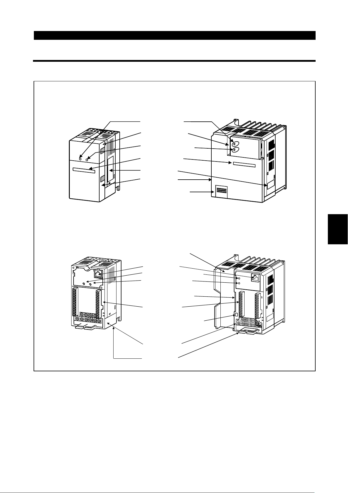
1.3.1 Appearance and structure
(1) Front view
OUTLINE
100V class, 200V class
POWER lamp
(yellow)
Accessory cover
ALARM lamp (red)
Capacity plate
Rating plate
Front cover
Wiring port cover
for option
(2) Without accessory cover and front cover
100V class, 200V class
Inboard option
mounting position
PU conector*
POWER lamp (yellow)
ALARM lamp (red)
Connector for connection
of inboard option
(400V class only)
Control circuit
terminal block
Control logic changing
connector
(400V class only)
Main circuit
terminal block
(400V class)
1
(400V class)
Wirin
cover
*Use the PU connector for the FR-PA02
-02
or FR-PU04 option and RS-485
communication.
4
Page 17
OUTLINE
)2)3)
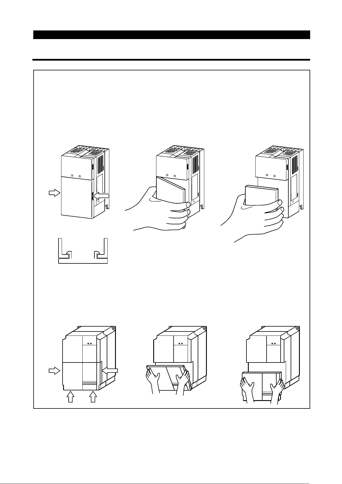
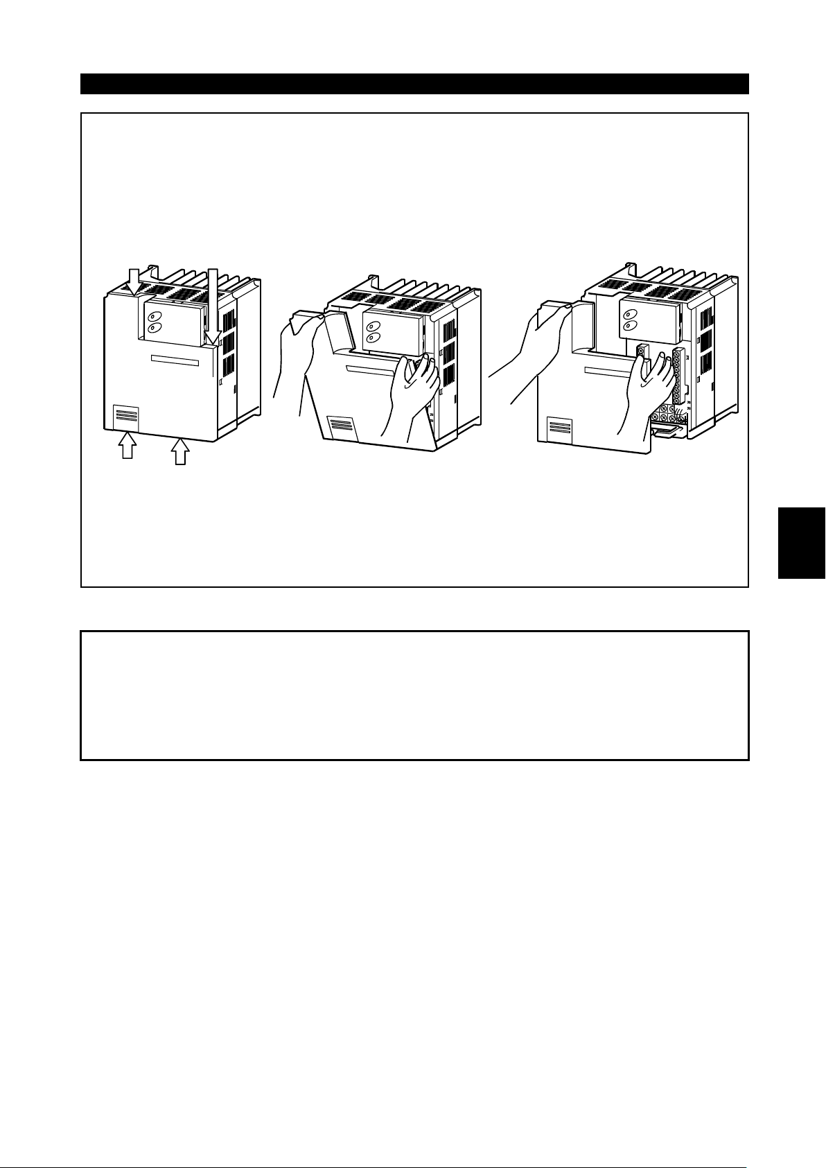
1.3.2 Removal and reinstallation of the front cover
""""
Removal
(For the FR-E520-0.1K to 3.7K-NA, FR-E510W-0.1K to 0.75K-NA)
The front cover is secured by catches in positions A and B as shown below.
Push either A or B in the direction of arrows, and using the other end as a
support, pull the front cover toward you to remove.
1
A
B
(For the FR-E520-5.5K, 7.5K-NA)
The front cover is fixed with catches in positions A, B and C.
Push A and B in the directions of arrows at the same time and remove the
cover using C as supporting points.
1) 2) 3)
A
C
C
B
5
Page 18
OUTLINE
)
(For the FR-E540-0.4K to 7.5K-NA)
The front cover is fixed with catches in positions A, B and C.
Push A and B in the directions of arrows at the same time and remove the
cover using C as supporting points.
1
A B
C
"
" Reinstallation
""
C
2) 3)
When reinstalling the front cover after wiring, fix the catches securely.
With the front cover removed, do not switch power on.
Note:1. Make sure that the front cover has been reinstalled securely.
1
2. The same serial number is printed on the capacity plate of the front cover
and the rating plate of the inverter. Before reinstalling the front cover, check
the serial numbers to ensure that the cover removed is reinstalled to the
inverter from where it was removed.
6
Page 19
OUTLINE
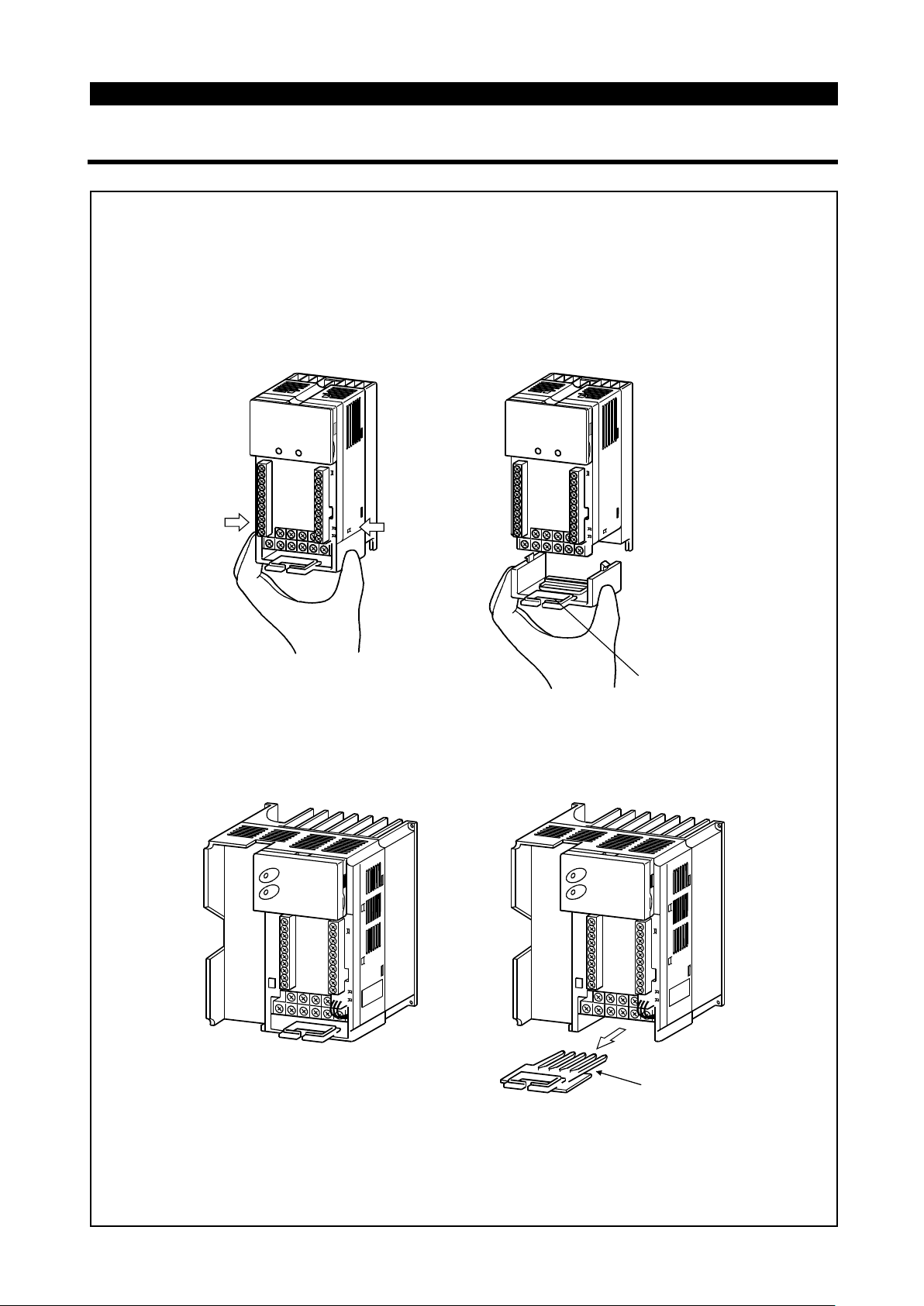
1.3.3 Removal and reinstallation of the wiring cover
""""
Removal
(For the FR-E520-0.1K to 7.5K-NA, FR-E510W-0.1K to 0.75K-NA)
The wiring cover is fixed by catches in positions 1) and 2).
Push either 1) or 2) in the direction of arrows and pull the wiring cover
downward to remove.
1)
2)
(For the FR-E540-0.4K to 7.5K-NA)
Remove the wiring cover by pulling it in the direction of arrow A.
Wiring hole
A
Wiring hole
""""
Reinstallation
Pass the cables through the wiring hole and reinstall the cover in the original
position.
7
Page 20

OUTLINE
1.3.4 Removal and reinstallation of the accessory cover
""""
Removal of the accessory cover
Hold down the portion A indicated by the arrow and lift the right hand side using
the portion B indicated by the arrow as a support, and pull out the accessory
cover to the right.
1)
""""
Reinstallation of the accessory cover
2)
A
B
3)
Insert the mounting catch (left hand side) of the accessory cover into the
mounting position of the inverter and push in the right hand side mounting
catch to install the accessory cover.
Mounting position
1
1)
Accessory cover
Catch
2)
A
3)
8
Page 21
OUTLINE
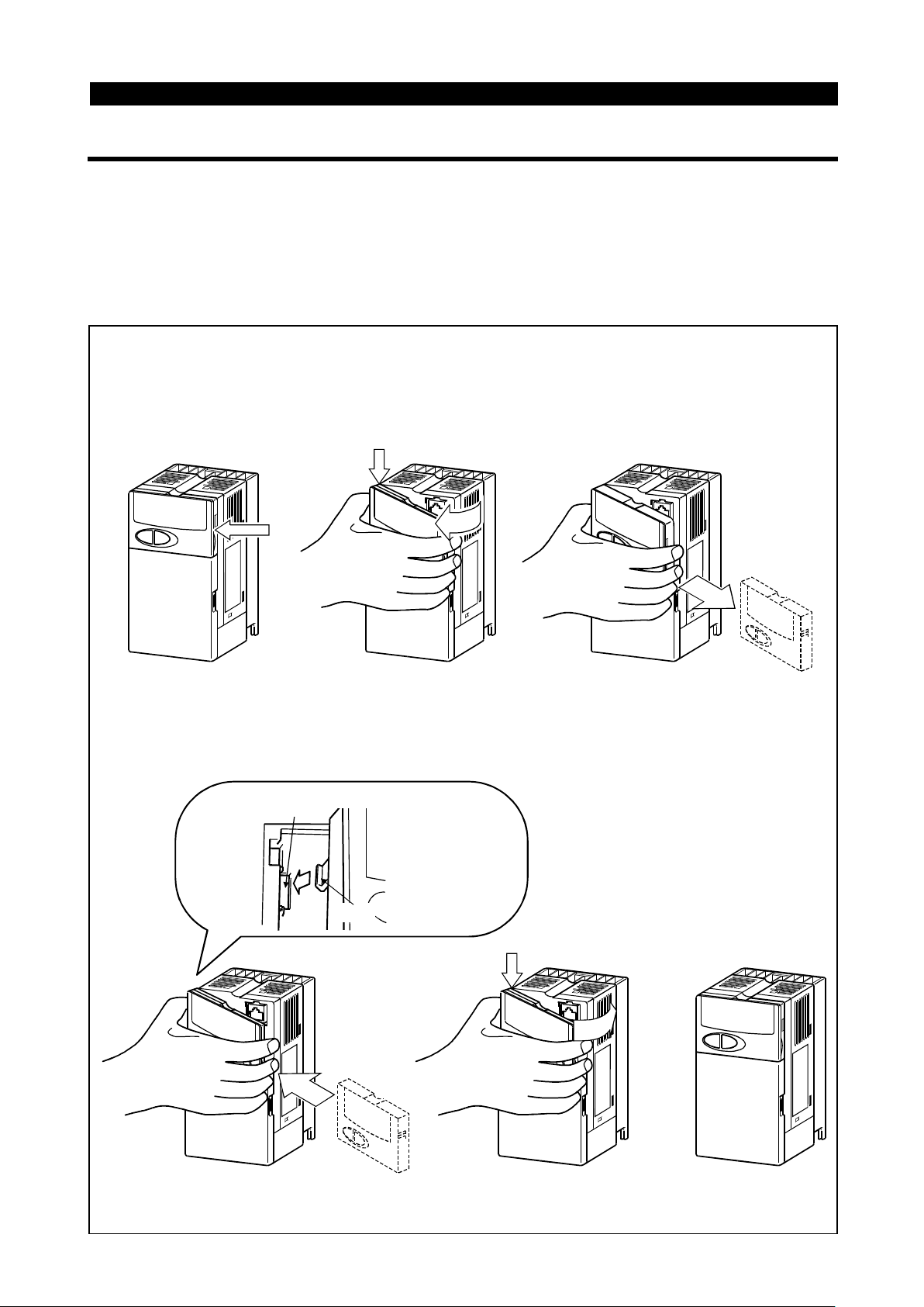
1.3.5 Reinstalla tion and removal of the control panel
To ensure safety, reinstall and removal the optional control panel (FR-PA02-02) after
switching power off.
The charging area and control printed board are exposed on the rear surface of the
control panel. When removing the control panel, always fit the rear cover option
FR-E5P. Never touch the control printed board because touching it can cause the
inverter to fail.
""""
Reinstallation of the control panel
Insert the mounting catch (left hand side) of the control panel into the
mounting position of the inverter and push in the right hand side mounting
catch to install the control panel.
1) 2)
A
B
3)
""""
Removal of the control panel
Hold down the portion A indicated by the arrow and lift the right hand side
using the portion B indicated by the arrow as a support, and pull out the
control panel to the right.
Mounting position
2)
02
A
3)
FR-PA02-
Catch
1)
(If the above procedure is not used for removal, the internal connector may be
damaged by the force applied.)
9
Page 22
OUTLINE
(
)
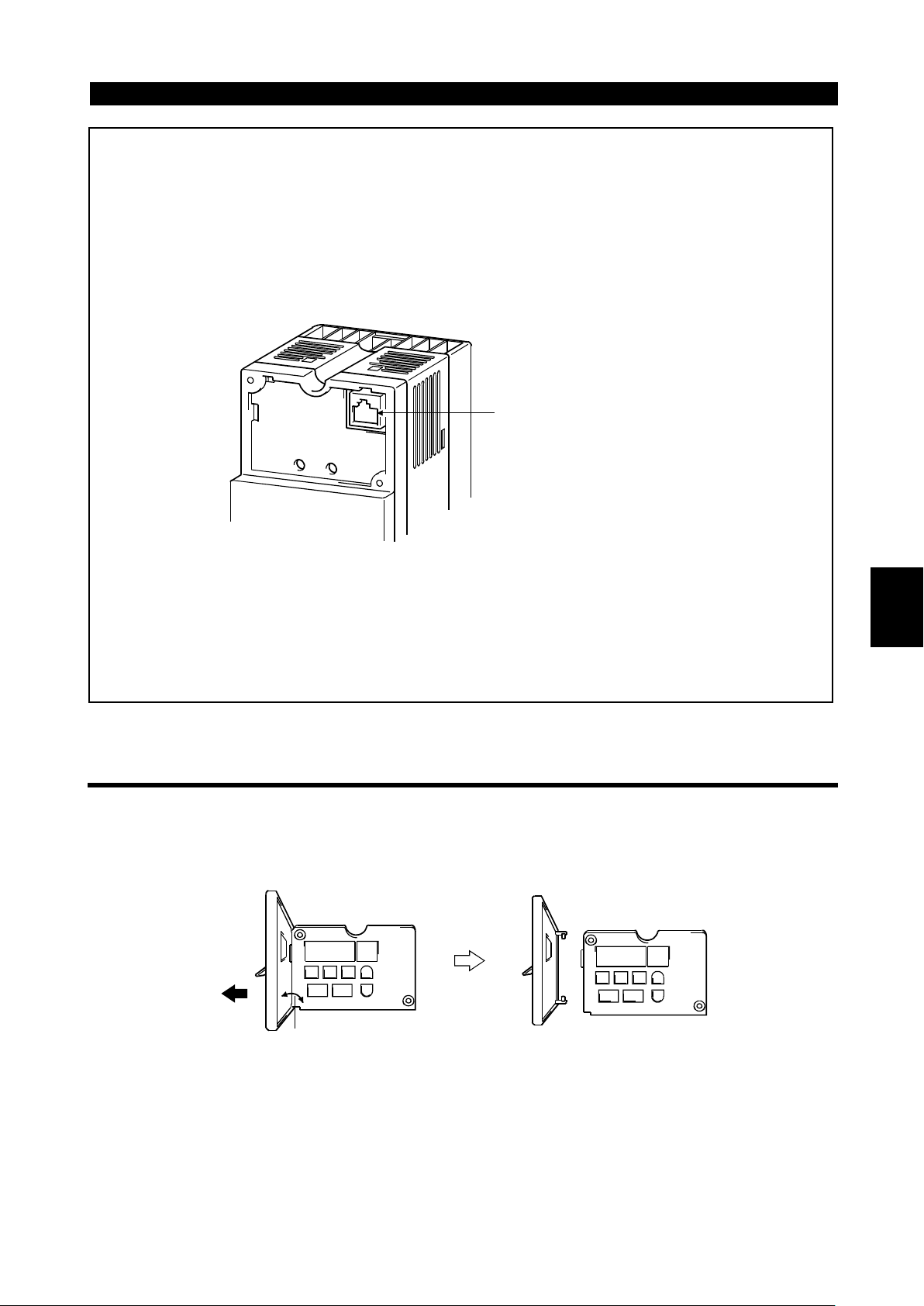
"
" Using the connection cable for operation
""
1) Fit the rear cover option FR-E5P to the back surface of the optional control
panel.
2) Securely plug one end of the connection cable into the PU connector of the
inverter and the other end into the adaptor of the FR-E5P option to connect it
to the control panel. (For the connection cable of the FR-E5P, refer to page
27.)
PU connector
RS-485 cable specifications
"
" Mounting the control panel on an enclosure
""
When you open the control panel front cover, the screw mounting guides for
fixing the control panel to an enclosure appear on the top left and bottom right.
Fit the rear cover of the FR-E5P option, drill holes in the control panel mounting
guides, and securely mount the control panel on the enclosure with screws.
1.3.6 Removal of the control panel (FR-PA02-02) front cover
1) Open the control panel front cover to 90 degrees.
2) Pull out the control panel front cover to the left to remove it.
1
90 degrees
10
Page 23
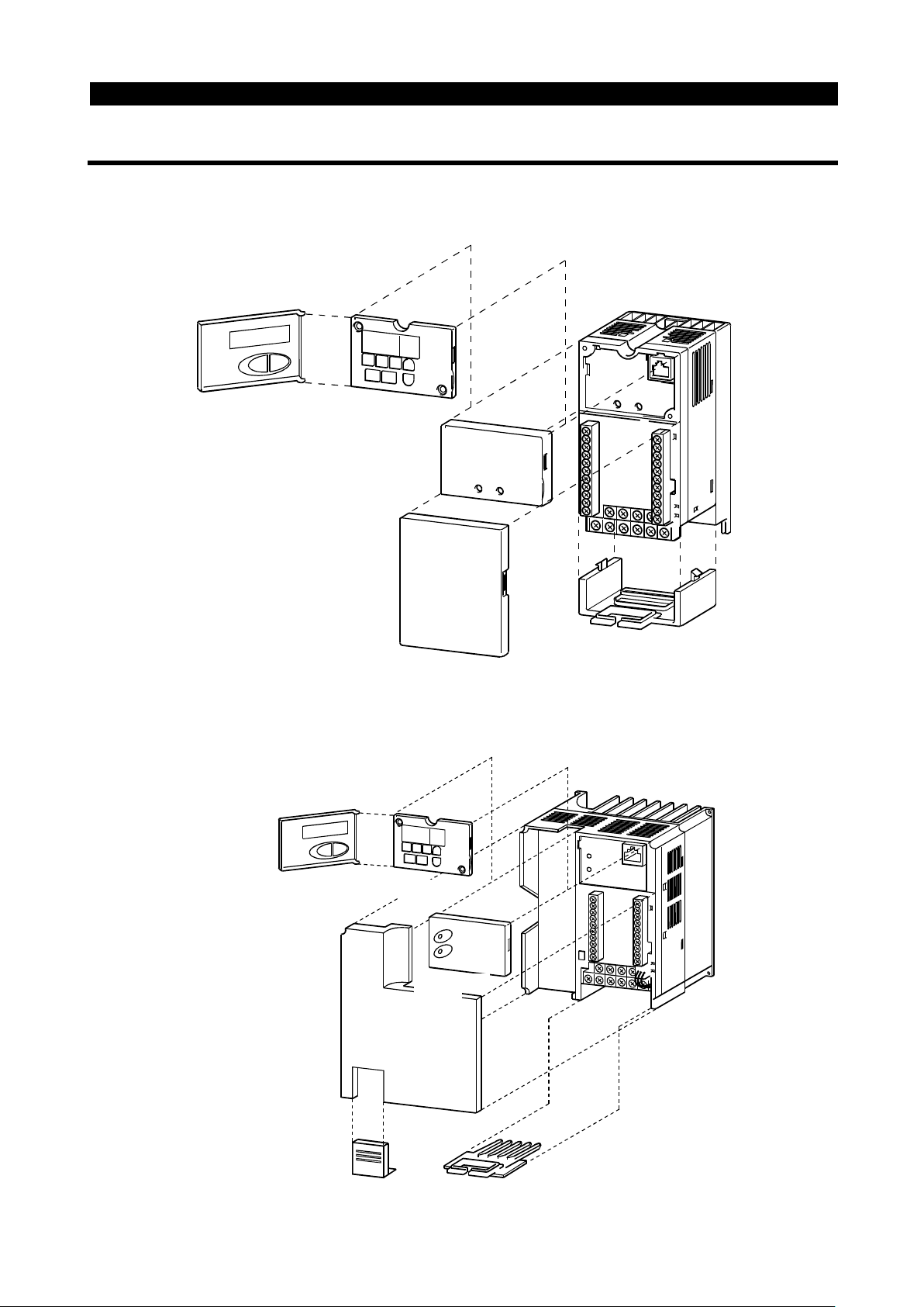
1.3.7 Exploded view
ont cove
W
f
""""
FR-E520-0.1K to 7.5K-NA
""""
FR-E510W-0.1K to 0.75K-NA
OUTLINE
Control panel (FR-PA02 )
""""
FR-E540-0.4K to 7.5K-NA
-02
Accessory cover
Fr
Wiring cover
r
Control panel (FR-PA02-02)
Front cover
iring port cover
or option
Accessory
cover
Wiring cover
11
Page 24

C H A P T E R 2
CHAPTER 2
INSTALLATION AND
INSTALLATIONAND
WIRINNG
WIRING
This chapter gives information on the basic "installation and
wiring" for use of this product.
Always read the instructions in this chapter before using the
equipment.
2.1 Installation ....................................................................12
2.2 Wiring ...........................................................................14
2.3 Other Wiring ................................................................. 34
Chapter 1
Chapter 2
Chapter 3
Chapter 4
Chapter 5
Chapter 6
Page 25
2.1 Installation
)>
INSTALLATION AND WIRING
2 INSTALLATION AND WIRING
2.1 Installation
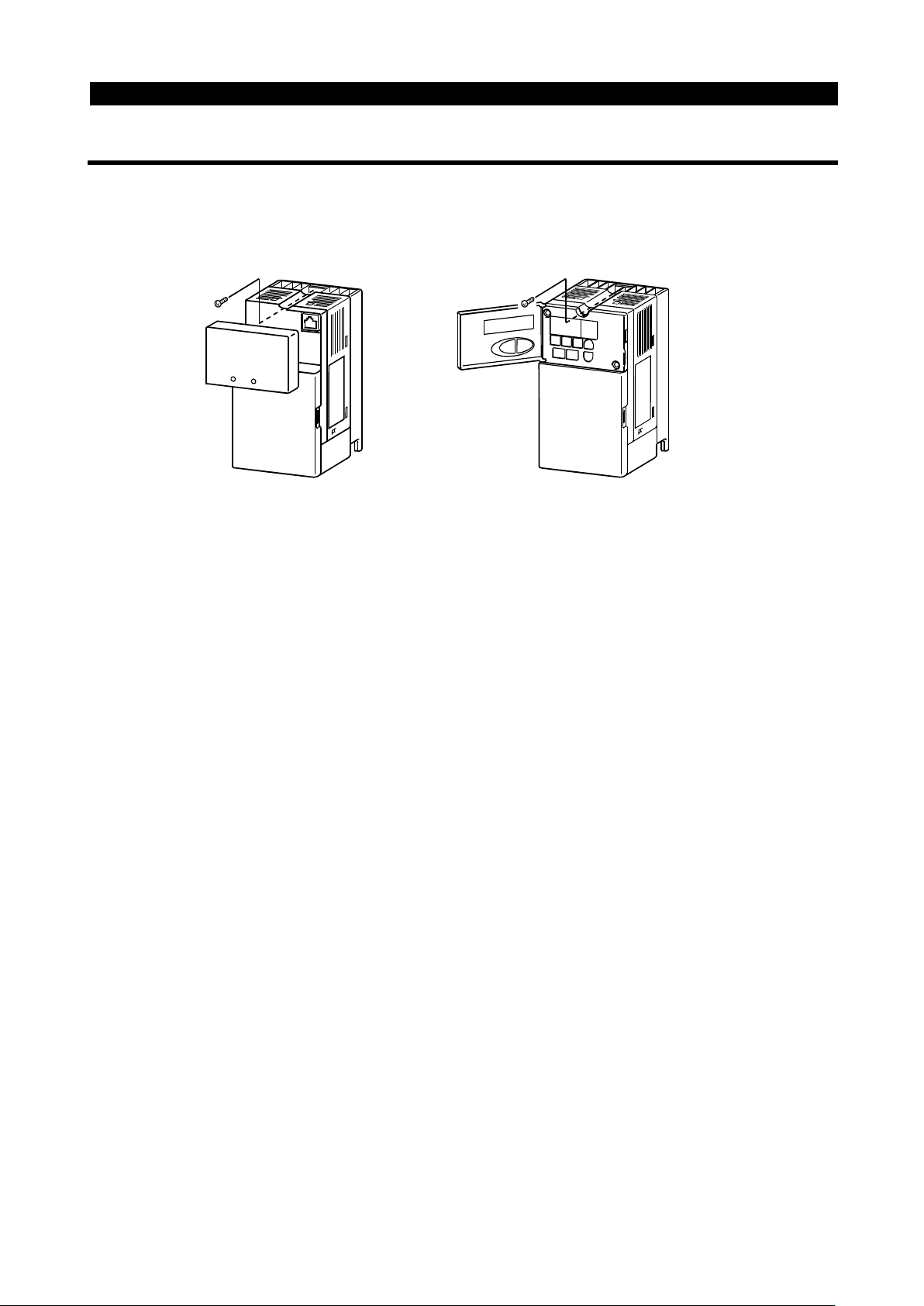
2.1.1 Instructions for installation
For the FR-E520-0.1K to 0.75K-NA and FR-E510W-0.1K to 0.4K-NA, install the
02
inverter with the accessory cover or control panel (FR-PA02-
) front cover open.
<For the accessory cover> <For the control panel (FR-PA02
-02
1) Handle the unit carefully.
The inverter uses plastic parts. Handle it gently to protect it from damage.
Also, hold the unit with even strength and do not apply too much strength to the front
cover alone.
2) Install the inverter in a place where it is not affected by vibration easily (5.9m/s
maximum).
Note the vibration of a cart, press, etc.
2
3) Note on ambient temperature.
The inverter life is under great influence of ambient temperature. In the place of
installation, the ambient temperature must be within the permissible range -10°C to
+50°C (14°F to 122°F). Check that the ambient temperature is within that range in
the positions shown in figure 3).
4) Install the inverter on a non-combustible surface.
The inverter will be very hot (maximum about 150°C (302°F)). Install it on a noncombustible surface (e.g. metal). Also leave sufficient clearances around the
inverter.
5) Avoid high temperatures and high humidity.
Avoid direct sunlight and places of high temperature and high humidity.
6) Avoid places where the inverter is exposed to oil mist, flammable gases, fluff, dust,
dirt etc.
Install the inverter in a clean place or inside a "totally enclosed" panel which does
not accept any suspended matter.
12
Page 26

INSTALLATION AND WIRING
(
)
(
)
7) Note the cooling method when the inverter is installed in an enclosure.
When two or more inverters are installed or a ventilation fan is mounted in an
enclosure, the inverters and ventilation fan must be installed in proper positions with
extreme care taken to keep the ambient temperatures of the inverters with the
permissible values. If they are installed in improper positions, the ambient
temperatures of the inverters will rise and ventilation effect will be reduced.
8) Install the inverter securely in the vertical direction with screws or bolts.
3) Note on ambient
temperatures
Measurement
position
5cm
1.97inch
5cm
1.97inch
FR-E500
Measurement position
5cm
(1.97inch)
7) For installation in an enclosure
Ventilation
fan
Inverter
(Correct example) (Incorrect example)
Position of Ventilation Fan
Inverter
4) Clearances around the inverter
10cm (3.94inch)
or more
1cm (0.39inch)
or more*
These cleara nc es ar e a ls o necessary for cha nging the cooling fan.
Inverter
FR-E500
*5cm (1.97inch) or mor e for 5.5K and 7.5K
Built-in cooling fan
(Correct example)
1cm (0.39inch)
or more*
10cm (3.94inch)
or more
Inverter
Leave sufficient
clearances above
and under the
inverter to ensure
adequate ventilation.
Cooling fan
built in the
inverter
Inverter
Inverter
(Incorrect example)
Cooling air
2
8) Vertical mounting
13
Page 27

2.2 Wiring
g
p
)
q
q
p
2.2 Wiri ng
2.2.1 Terminal connection diagram
""""
3-phase 200V power input
""""
3-phase 400V power input
INSTALLATION AND WIRING
3-phase
AC power
supply
24VDC power output and
external transistor commo n
Multi-speed selection
Control input signals
(no voltage input allowed)
Frequency setting signals (analog)
(Note 1)
Frequency
setting
potentiometer
1/2W1k
NFB
Forward rotation start
Reverse rotation start
Contact input common
3
1
Current input(-)
Ω
4 to 20mADC(+)
MC
High
Middle
Low
Output stop
Reset
2
)
R(L
1
)
S(L
2
3
T(L
)
PC
Note 5
STF
STR
RH
RM
RL
MRS
RES
SD
Note 4
10(+5V)
0 to 5VDC
2
0 to 10VDC
5(Common)
Note 4
4(4 to 20mADC)
Selected
PU connector
(RS-485)
P1
(+)P
PR
(-)N
Note 2
RUN
FU
SE
Note 3
FM
SD
Note 3
AM
U
V
W
Jumper
Remove this jumper when
using the optional power-factor
improving DC reactor.
Brake resistor connection
A
B
C
5
Alarm
output
Running
Frequency detection
Open collector
output common)
(e.g. frequency meter)
+
Calibration
resistor (Note 6)
Ground
Main circuit termina l
Control circuit input terminal
Control circuit output terminal
Meter
Moving-coil
type1mA
full-scale
Analog signal
(+)
output
(−)
(0 to 10VDC)
Motor
IM
Ground
Open
collector outputs
For 200V
and100V
class
inverters
For 400V
class
inverter
Note:1. If the potentiometer is to be operated often, use a 2W1kΩ potentiometer.
2. 0.1K and 0.2K do not contain a transistor.
3. Terminals SD and SE are isolated.
4. Terminals SD and 5 are common terminals. Do not earth them to the
round. Terminals SD and 5 are not isolated. (Those of the 400V class are
isolated.)
5. When terminals PC-SD are used as a 24VDC
ower supply, be careful not
to short these terminals. If they are shorted, the inverter will be damaged.
02
6. Not needed when the control panel (FR-PA-02-
PU04
fre
the fre
is used for calibration. Used when calibration must be made near the
uency meter for such a reason as a remote frequency meter. However,
uency meter needle may not deflect to full-scale if the calibration
) or parameter unit (FR-
resistor is connected. In this case, use this resistor and the control
parameter unit together.
14
anel or
Page 28
"
" Single-phase 100V power input
""
INSTALLATION AND WIRING
NFB
Power supply
MC
R (L
S (L
)
1
)
2
U
V
W
Motor
IM
Ground
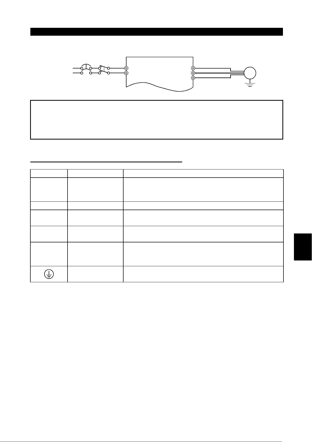
Note:1. To ensure safety, connect the power input to the inverter via a magnetic
contactor and earth leakage circuit breaker or no-fuse breaker, and use the
magnetic contactor to switch power on-off.
2. The output is three-phase 200V.
(1)
Description of the main circuit terminals
Symbol Terminal Name Description
R, S, T
, L2, L3)
(L
1
AC power input
(Note)
U, V, W Inverter output Connect a three-phase squirrel-cage motor.
P (+), PR
P (+), N (−)
Brake resistor
connection
Brake unit
connection
Power factor
P (+), P1
improving DC
reactor connection
Connect to the commercial power supply. Keep these
terminals unconnected when using the high power factor
converter.
Connect the optional brake resistor across term inals P-PR
(+ - PR) (not for 0.1K and 0.2K).
Connect the optional brake unit or high power factor
converter.
Disconnect the jumper f rom terminals P-P1 (+ - P1) and
connect the optional power factor improving DC reactor.
2
Ground For grounding the inverter chassis. Must be earthed.
Note: R, S (L1, L2) terminals for single-phase power input.
15
Page 29

(2)
Description of the control circuit terminals
INSTALLATION AND WIRING
Type Symbol
STF
STR
RH, RM,RLMulti-speed
MRS Output stop
Input signals
Analog
RES Reset
SD
Contacts, e.g. start (STF), stop (STOP) etc
PC
10
2
4
Frequency setting
5
Terminal
Name
Forward
rotation start
Reverse
rotation start
selection
Contact input
common
(sink*)
Power output
and external
transistor
common
Contact input
common
(source*)
Frequency
setting power
supply
Frequency
setting
(voltage)
Frequency
setting
(current)
Frequency
setting input
common
Description
When the STF
Turn on the STF signal to start forward
rotation and turn it off to stop.
Turn on the STR signal to start reverse
rotation and turn it off to stop.
Combine the RH, RM and RL signals
as appropriate to select multiple
speeds.
Turn on the MRS signal (20ms or
longer) to stop the inverter output.
Used to shut off the inverter output to
bring the motor to a stop by the
electromagnetic brake.
Used to reset the protective circuit activated. Turn on the
RES signal for more than 0.1 second then turn it off.
Common to the contact input terminals and terminal FM.
Common output terminal for 24VDC 0.1A power output
(PC terminal).
When transist or output (open collector output), such as a
programmable controller (PLC), is connected, connect the
external power supply common for transistor output to this
terminal to prevent a fault caused by undesirable current.
This terminal can be used as a 24VDC, 0.1A power
output.
5VDC, permissible load current 10m A
By entering 0 to 5VDC (0 to 10VDC), the maximum output
frequency is reached at 5V (or 10V) and I/O are
proportional. Use Pr. 73 to switch between input 0 to
5VDC (factory setting) and 0 to 10VDC. Input resistance
10kΩ. Maximum permissible voltage 20V.
By entering 4 to 20mADC, the m aximum output frequency
is reached at 20mA and I/O are proportional. This input
signal is valid only when the AU signal is on. Input
resistance 250Ω. Maximum permissible current 30mA.
Common to the frequency setting signals (terminal 2, 1 or 4).
Do not connect to the earth.
and STR signals
are turned on
simultaneously,
the stop
command is
given.
Input terminal
function choices
(Pr. 180 to
Pr. 183) change
terminal functions.
Note: Assign the AU signal to any of the terminals using the input terminal function
selection (Pr. 180 to Pr. 183).
* Used as a contact input signal common terminal for the 400V class by switching
between sink logic and source logic. (Refer to page 23).
16
Page 30

INSTALLATION AND WIRING
Type Symbol
A, B, C Alarm output
Contact
RUN
FU
Open collector
Output signals
SE
FM
(200V
and
100V
Pulse
class
inverters)
AM
(400V
class
Analog
only)
Terminal
Name
Inverter
running
Frequency
detection
Open collector
output
common
For meter
Analog signal
output
Description
Contact output indicating that t he output has
been stopped by the inverter protective
function activated. 230VAC 0.3A, 30VDC
0.3A. Alarm: discontinuity across B-C
(continuity across A-C), normal: continuity
across B-C (discontinuity across A-C).
Switched low when the inverter output
frequency is equal to or higher than the
starting frequency (factory set to 0.5Hz,
variable). Switched high during stop or DC
injection brake operation (*1).
Permissible load 24VDC 0.1A.
Switched low when the output frequency has
reached or exceeded the detection frequency
set as appropriate. Switched high when below
the detection frequency (*1).
Permissible load 24VDC 0.1A
Common to t he RUN and FU terminals.
Factory setting of output item:
One selected from output
frequency, motor current
and output voltage is
output (*2). The output
signal is proportional to
the magnitude of each
monitoring item.
Frequency
Permissible load current 1mA
1440 pulses/s at 60Hz
Factory setting of output item:
Frequency
Output signal 0 to 10 VDC
Permissible load current 1mA
Output
terminal
function
choices
(Pr. 190 to
Pr. 192)
change
terminal
functions.
2
With the control panel connector, communication can be
made using the RS-485 protocol.
Conforming Standard : EIA Standard RS-485
!
Transmission format : Multi-drop link
!
Communication speed : Maximum 19200 bps
!
Overall length : 500m (1640.40 feet)
!
Communication
RS-485
PU connector
*1: Low indicates that the open collector output transistor is on (conducts). High
indicates that the transistor is off (does not conduct).
*2: Not output during inverter resetting.
17
Page 31

INSTALLATION AND WIRING
3
)
2.2.2 Wiring of the main circuit
(1)
Wiring instructions
1) It is recommended to use insulation-sleeved solderless terminals for power supply
and motor wiring.
2) Power must not be applied to the output terminals (U, V, W) of the inverter.
Otherwise the inverter will be damaged.
3) After wiring, wire off-cuts must not be left in the inverter.
Wire off-cuts can cause an alarm, failure or malfunction. Always keep the inverter
clean.
When drilling mounting holes in a control box etc., be careful so that chips and
others do not enter the inverter.
4) Use thick cables to make the voltage drop 2% or less.
If the wiring distance is long between the inverter and motor, a main circuit cable
voltage drop will cause the motor torque to decrease, especially at the output of a
low frequency. (A selection example for the wiring length of 20m (65.62 feet) is
shown on page 21.)
5) For long distance wiring, the overcurrent protection may be activated improperly or
the devices connected to the output side may misoperate or become faulty under
the influence of a charging current due to the stray capacitance of the wiring.
Therefore, the maximum overall wiring length should be as indicated in the following
table. If the wiring length exceeds the value, it is recommended to set "1" in Pr. 156 to
make the fast-response current limit function invalid. (When two or more motors are
connected to the inverter, the total wiring length should be within the indicated value.)
Inverter Capacity 0.1K 0.2K 0.4K 0.75K 1.5K 2.2K
Non-low
acoustic noise
mode
Low acoustic
noise mode
100V,
200V
class
400V
class
100V,
200V
class
400V
class
200
(656.16)
——
30
(98.42)
——
200
(656.16)
100
(328.08)
300
(984.24 )
200
(656.16)
200
(656.16)
30
(98.42)
500
(1640.40)
200
(656.16)
300
(984.24)
100
(328.08)
500
(1640.40)
300
(984.24)
500
(1640.40)
200
(656.16)
(1640.40)
(1640.40)
(1640.40)
(984.24)
Overall wiring length (3.7K or more)
500m (1640.40 feet)
maximum
300m
(984.24 feet)
300m
(984.24 feet)
500
500
500
300
(Unit: m (feet))
3.7K or
more
500
(1640.40)
500
(1640.40)
500
(1640.40)
500
(1640.40)
00m (984.24 feet)+300m (984.24 feet)=600m (1968.48 feet
18
Page 32

INSTALLATION AND WIRING
g
g
)
pp
g
g
q
p
g
6) Connect only the recommended optional brake resistor between the terminals P-PR
(+ - PR). Keep terminals P-PR (+ - PR) of 0.1K or 0.2K open.
These terminals must not be shorted.
0.1K and 0.2K do not accept the brake resistor. Keep terminals P-PR (+ - PR) open.
Also, never short these terminals.
7) Electromagnetic wave interference
The input/output (main circuit) of the inverter includes harmonic components, which
may interfere with the communication devices (such as AM radios) used near the
inverter. In this case, install the FR-BIF optional radio noise filter (for use in the input
side only) or FR-BSF01 or FR-BLF line noise filter to minimize interference.
8) Do not install a power capacitor, surge suppressor or radio noise filter (FR-BIF
option) in the output side of the inverter.
This will cause the inverter to trip or the capacitor and surge suppressor to be
damaged. If any of the above devices are installed, immediately remove them.
(When using the FR-BIF radio noise filter with a single-phase power supply, connect
it to the input side of the inverter after isolating the T phase securely.)
9) W hen rewiring after operation, make sure that the POWER lamp has gone off, and
when more than 10 minutes has elapsed after power-off, check with a meter etc.
that the voltage is zero. After that, start rewiring work. For some time after power-off,
there is a dangerous voltage in the capacitor.
Notes on Grounding
"
Leaka
and motor must be grounded.
"
Use the dedicated
in the case, chassis, etc.
aluminium and co
contain zinc. When ti
the aluminium frame.
"
The
e
as short as
inverter to minimize the ground cable length.
2.2kW (3HP) or less 2 (2.5)
3.7kW (5HP)
5.5kW (7. 5HP), 7.5kW (10HP)
To meet the Low Volta
specified size in brackets ( ).
e currents flow in the inverter. To prevent an electric shock, the inverter
round terminal to ground the inverter. (Do not use the screw
For the earth connection avoid direct contact between
er. Tin-plated cable lugs can be used if the plating does not
htening the screws take care not to damage the thread in
round cable should be as thick as possible. Use the cable whose gauge is
ual to or larger than those indicated in the following table, and make its length
ossible. The grounding point should be as near as possible to the
(Unit: mm2)
Ground Cable Gauge
100V class
200V class 400V class
2 (2.5) 2 (2.5)
3.5 (4) 2 (4)
e Directive, use PVC insulated cables larger than
2
"
Ground the motor on the inverter side using one wire of the 4-core cable.
19
Page 33

(2)
(
)
(
)
(
)
)
Terminal block layout of the power circ ui t
INSTALLATION AND WIRING
FR-E520-0.1K-NA, 0.2K-NA, 0.4K-NA,
0.75K-NA
P1N/- P/+ PR
UVW
R/L1S/L2T/L
3
Screw size (M3 . 5 )
TB1
Screw size
M3.5
FR-E520-5.5K-NA, 7.5K-NA
R/L1S/L2T/L3N/-
P1
Screw size (M5)
PR V WP/+
U
TB1
Screw size
(M5)
FR-E540-0.4K to 7.5K-NA
P1N/- P/+ PR
R/L1S/L2T/L
3
UVW
TB1
Screw size (M4 )
FR-E520-1.5K-NA, 2.2K-NA, 3.7K-NA
N/- P/+
P1
PR
TB2
Screw size (M4 )
R/L1S/L2T/L
3
UVW
Screw size (M4 )
TB1
Screw size (M4 )
Screw size (M4 )
FR-E510W-0.1K-NA, 0.2K-NA, 0.4K-NA
P1N/- P/+ PR
R/L1S/L
2
Screw size
UVW
TB1
Screw size
M3.5
M3.5
FR-E510W-0.75K-NA
N/- P/+
P1
PR
TB2
Screw size (M4)
R/L1S/L
2
Screw size (M4)
UVW
TB1
Screw size (M4
20
Page 34

INSTALLATION AND WIRING
(3)
Cables, crimping terminals, etc.
The following table lists the cables and crimping terminals used with the inputs (R (L1),
2
S (L
), T (L3)) and outputs (U, V, W) of the inverter and the torques for tightening the
screws:
1) FR-E520-0.1K-NA to 7.5K-NA
Applicable
Inverter Type
FR-E520-0.1K-NA
to 0.75K-NA
FR-E520-1.5K-NA,
2.2K-NA
FR-E520-3.7K-NA M4 1.5 5.5-4 5.5-4 3.5 3.5 12 12 4 2.5
FR-E520-5.5K-NA M5 2.5 5.5-5 5.5-5 5.5 5.5 10 10 6 4
FR-E520-7.5K-NA M5 2.5 14-5 8-5 14 8 6 8 16 6
Terminal
Screw
Size
M3.5 1.2 2-3.5 2-3.5 2 2 14 14 2.5 2.5
M4 1.5 2-4 2-4 2 2 14 14 2.5 2.5
Tight-
ening
Torque
N
m
⋅⋅⋅⋅
Crimping
Terminals
R, S, T
(L1, L2, L3)
U, V, W
mm
R, S, T
(L1, L2, L3)
Cables
2
U, V, W
AWG mm
R, S, T
(L1, L2, L3)
U, V, W
PVC insulated
Cables
R, S, T
(L1, L2, L3)
2
U, V, W
2) FR-E540-0.4K-NA to 7.5K-NA
Applicable
Inverter Type
FR-E540-0.4K-NA M4 1.5 2-4 2-4 2 2 14 14 2.5 2.5
FR-E540-0.75K-NA M4 1.5 2-4 2-4 2 2 14 14 2.5 2.5
FR-E540-1.5K-NA M4 1.5 2-4 2-4 2 2 14 14 2.5 2.5
FR-E540-2.2K-NA M4 1.5 2-4 2-4 2 2 14 14 2.5 2.5
FR-E540-3.7K-NA M4 1.5 2-4 2-4 2 2 14 14 2.5 2.5
FR-E540-5.5K-NA M4 1.5 5.5-4 2-4 3.5 2 12 14 4 2.5
FR-E540-7.5K-NA M4 1.5 5.5-4 5.5-4 3.5 3.5 12 12 4 4
Terminal
Screw
Size
Tight-
ening
Torque
N
m
⋅⋅⋅⋅
Crimping
Terminals
R, S, T
(L1, L2, L3)
U, V, W
mm
R, S, T
(L1, L2, L3)
Cables
2
U, V, W
AWG mm
R, S, T
(L1, L2, L3)
U, V, W
PVC insulated
Cables
R, S, T
(L1, L2, L3)
2
U, V, W
2
3) FR-E510W-0.1K-NA to 0.75K-NA
Cables
2
U, V, W
AWG mm
R, S
(L1, L2)
Applicable
Inverter Type
FR-E510W-0.1K
-NA to 0.4K-NA
FR-E510W-0.75K
-NA
Terminal
Screw
Size
M3.5 1.2 2-3.5 2-3.5 2 2 14 14 2.5 2.5
M4 1.5 5.5-4 2-4 3.5 2 12 14 4 2.5
Tight-
ening
Torque
N
m
⋅⋅⋅⋅
Crimping
Terminals
R, S
(L1, L2)
U, V, W
mm
R, S,
(L1, L2)
Note:1. The cables used should be 75°C (167°F) copper cables.
2. Tighten the terminal screws to the specified torques.
Undertightening can cause a short or misoperation.
Overtightening can cause the screws and unit to be damaged, resulting in a
short or misoperation.
21
U, V, W
PVC insulated
Cables
2
R, S
(L1, L2)
U, V, W
Page 35

(4)
T
t
s
(
Connection of the power suppl y and motor
"
" Three-phase power input
""
Three-phase
power supply 200V
Three-phase
power supply 400V
No-fuse
breaker
Ground
terminal
Ground
R
)S(L2)T(L3)
(L
1
R
(L1)S(L2)T(L3)
UVW
U
INSTALLATION AND WIRING
W
Motor
Ground
V
he power supply cables must be connected
o R, S, T (L , L , L ). If the y ar e connected to
U, V, W, the inverter will be damaged. (Phase
equence need not be matched.)
"
" Single-phase power input
""
1 2 3
Single-phase power
supply 100V
Ground
No-fuse
breaker
terminal
Ground
R
(L1)S(L2)
R
1
(L
)S(L2)
Note:1. To ensure safety, connect the power input to the inverter via a
magnetic contactor and earth leakage circuit breaker or no-fuse
breaker, and use the magnetic contactor to switch power on-off.
2. The output is three-phase 200V.
Connect the motor to U, V, W.
connection, turning on the forward rotation switch (signal)
rotates the motor in the counterclockwise
when viewed from the load shaft.
UVW
UVW
Motor
In the above
arrow) direction
Ground
2.2.3 Wiring of the control circuit
(1)
Wiring instructions
1) Terminals SD, SE and 5 are common to the I/O signals. These common terminals
must not be earthed to the ground.
Terminals SD and 5 are not isolated. (Those of the 400V class are isolated.)
2) Use shielded or twisted cables for connection to the control circuit terminals and run
them away from the main and power circuits (including the 200V relay sequence
circuit).
3) The frequency input signals to the control circuit are micro currents. W hen contacts
are required, use two or more parallel micro signal contacts or a twin contact to
prevent a contact fault.
4) It is recommended to use the cables of 0.3mm2 to 0.75mm2 gauge for connection to
the control circuit terminals.
5) W hen bar terminals and solid wires are used for wiring, their diameters should be
0.9mm (0.04 inches) maximum If they are larger, the screw threads may be
damaged during tightening.
22
Page 36

INSTALLATION AND WIRING
)
(2)
Terminal block layout
In the control circuit of the inverter, the terminals are arranged as shown below:
Terminal screw size: M2.5
(200V class, 100V class) (400V class)Terminal layout of control circuit
RH
RM
RL
MRS
RES
SD
FM*
PC
SE
RUN
FU
A
B
C
10
2
5
4
SD
STF
STR
SD
*AM for the 400V class inverter.
(3)
Wiring method
1) For wiring the control circuit, use cables after stripping their sheaths.
Refer to the gauge printed on the inverter and strip the sheaths to the following
dimensions. If the sheath is stripped too much, its cable may be shorted with the
adjoining cable. If the sheath is stripped too little, the cable may come off.
2
7mm±1mm (0.28inches± 0.04inches
2) When using bar terminals and solid wires for wiring, their diameters should be
0.9mm maximum. If they are larger, the threads may be damaged during tightening.
3) Loosen the terminal screw and insert the cable into the terminal.
4) Tighten the screw to the specified torque.
Undertightening can cause cable disconnection or misoperation. Overtightening can
cause damage to the screw or unit, leading to short circuit or misoperation.
⋅
Tightening torque: 0.25 N
m to 0.49 N⋅m
* Use a size 0 screwdriver.
Note: When routing the stripped cables, twist them so that they do not become loose.
In addition, do not solder them.
(4) Control logic changing (400V class only)
For the 200V and 100V class inverters, the logic cannot be changed.
The input signal logic is factory-set to the sink mode.
To change the control logic, the position of the connector beside the control circuit
terminal block must be changed.
23
Page 37

INSTALLATION AND WIRING
1) Use tweezers etc. to remove the connector in the sink logic position and fit it in the
source logic position.
Do this position changing before switching power on.
Note:1. Make sure that the front cover has been installed securely.
2. The front cover has a capacity plate and the inverter a rating plate on it.
Since these plates have the same serial numbers, always reinstall the
removed cover to the inverter from where it was removed.
3. Always install the sink-source logic changing connector in either of the
positions. If two connectors are installed in these positions at the same time,
the inverter may be damaged.
2) Sink logic type
•
In this logic, a signal switches on when a current flows out of the corresponding
signal input terminal.
Terminal SD is common to the contact input signals. Terminal SE common to the
open collector output signals.
•
Current
STF
STR
SD
R
R
Current flow related to
RUN signal
Inverter
RUN
SE
24VDC
AX40
1
9
R
R
24
Page 38

INSTALLATION AND WIRING
C
•
When using an external power supply for transistor output, use terminal PC as a
common to prevent misoperation caused by undesirable current.
(Do not connect terminal SD of the inverter with terminal 0V of the external power
supply. When using terminals PC-SD as a 24VDC power supply, do not install the
power supply in parallel outside the inverter. Doing so may cause misoperation due
to undesirable current.)
Y40 type
ransistor
utput module
Inverter
24VD
(SD)
10
1
STF
2
STR
3
RH
4
RM
5
RL
6
RES
9
PC
24VDC
SD
3) Source logic type
•
In this logic, a signal switches on when a current flows into the corresponding signal
input terminal.
Terminal PC is common to the contact input signals. Terminal SE common to the
open collector output signals.
2
• Current flow related to
Current
PC
STF
STR
RUN signal
R
R
Inverter
RUN
SE
24VDC
AX80
1
9
R
R
25
Page 39

INSTALLATION AND WIRING
C
(
)
•
When using an external power supply for transistor output, use terminal SD as a
common to prevent misoperation caused by undesirable current.
24VDC
PC
STF
STR
SD
Inverter
24VD
(SD)
AY-80
9
1
2
10
(5) How to use the STOP signal
The following connection example shows how to self-hold the start signals (forward
rotation, reverse rotation).
Use Pr. 180 to Pr. 183 (input terminal function selection) to assign the STOP signal.
RL
(STOP)
Stop
Forward
rotation
Reverse
rotation
MRS
RES
SD
STF
STR
Wiring example for sink logic
26
Page 40

INSTALLATION AND WIRING
2.2.4 Connection to the PU connector
(1)
When connecting the control panel or parameter unit using a cable
Use the option FR-CB2# or the following connector and commercially available cable:
<Connection cable>
!
Connector : RJ45 connector
Example: 5-554720-3, Tyco Electronics Corporation
!
Cable : Cable conforming to EIA568 (e.g. 10BASE-T cable)
Example: SGLPEV 0.5mm×4P (Twisted pair cable, 4 pairs),
MITSUBISHI CABLE INDUSTRIES, LTD.
<When using the control panel>
Note: The rear cover and junction adaptor are required since the circuit board is
exposed in the back of the control panel.
Use the FR-E5P option (cover and adaptor available as a set).
<Maximum w iring length>
!
Control panel (FR-PA02-
!
Parameter unit (FR-PU04): 20m (65.62 feet)
(2)
For RS-485 communication
02
): 20m (65.62 feet)
The PU connector can be used for communication
operation from a personal computer etc.
When the PU connector is connected with a
personal, FA or other computer by a
communication cable, a user program allows the
1) SG
2) P5S
3) RDA
4) SDB
8) to 1)
5) SDA
6) RDB
7) SG
8) P5S
inverter to be run and monitored and the parameter
values to be read and written.
<PU connector pin-outs>
Viewed from the inverter (receptacle side) front
Note: 1. Do not connect the PU connector to a computer's LAN board, FAX modem
socket or telephone modular connector. Otherwise, the product may be
damaged due to electrical specification differences.
2. Pins 2) and 8) (P5S) provide power to the control panel or parameter unit.
Do not use these pins for RS-485 communication.
2
27
Page 41

INSTALLATION AND WIRING
n
<System configuration examples>
1) When a computer having a RS-485 interface is used with several inverters
Computer
RS-485
interface/terminal
Computer
Station 1
Inverter
PU connector
(Note1)
Distribution
terminal
10BASE-T cable (Note 2)
Station 2
Inverter
PU connector
(Note1)
Station n
Inverter
PU connector
(Note1)
Use the connectors and cables which are available on the market.
Note:1. Connector: RJ45 connector
Example: 5-554720-3, Tyco Electronics Corporation
2. Cable :Cable conforming to EIA568 (such as 10BASE-T cable)
Example: SGLPEV 0.5mm × 4P (Twisted pair cable, 4 pairs),
Mitsubishi Cable Industries, Ltd.
2) When a computer having a RS-232C interface is used with inverters
Termination
resistor
Computer
RS-232C
connector
RS-232C
cable
RS-485
terminal
*Commercially available converter is required. (Note 3)
Max. 15m
(49.21 feet)
Converter*
Distribution
terminal
10BASE-T ca ble (Note 2)
Station 1
Inverter
PU connector
(Note1)
Use the connectors, cables and converter which are available on the market.
Note:1. Connector: RJ45 connector
Example: 5-554720-3, Tyco Electronics Corporation
2. Cable : Cable conforming to EIA568 (such as 10BASE-T cable)
Example: SGLPEV 0.5mm × 4P (Twisted pair cable, 4 pairs),
Mitsubishi Cable Industries, Ltd.
3.*Commercially available converter examples
Model: FA-T-RS40
Converter
Nagoya Sales Office, Mitsubishi Electric Engineering Co., Ltd.
Station 2
Inverter
PU connector
(Note1)
Station n
Inverter
PU connector
(Note1)
Terminatio
resistor
28
Page 42

<Wiring methods>
1) Wiring of one RS-485 computer and one inverter
INSTALLATION AND WIRING
Computer Side Terminals
Signal name Description
RDA
RDB
SDA
SDB
RSA
RSB
CSA
CSB
SG
FG
Receive data
Receive data
Send data
Send data
Request to send
Request to send
Clear to send
Clear to send
Signal ground
Frame ground
Cable connection and signal direction
10 BASE-T Cable
(Note 1)
0.3mm or more
2
PU connector
2) Wiring of one RS-485 computer and "n" inverters (several inverters)
Cable connection and signal direction
Computer
RDA
RDB
SDA
SDB
RSA
RSB
CSA
CSB
SG
FG
(Note 1)
RDB
SG
Station 1
Inverter Inverter Inverter
10 BASE-T Cable
RDA
SDB
SDA
RDB
RDA
SG
Station 2
SDB
SDA
RDB
RDA
SG
Station n
Inverter
SDA
SDB
RDA
RDB
SG
SDB
SDA
Termination
resistor
(Note 2)
2
Note:1. Make connections in accordance with the instruction manual of the
computer used.
Fully check the terminal numbers of the computer as they differ between
models.
2. There may be the influence of reflection depending on the transmission
speed and/or transmission distance. If this reflection hinders
communication, provide a termination resistor. If the PU connector is used
to make a connection, use the distributor as a termination resistor cannot be
fitted.
Connect the termination resistor to only the inverter remotest from the
computer. (Termination resistor: 100Ω)
29
Page 43

INSTALLATION AND WIRING
r
2.2.5 Connection of stand-alone option unit s
The inverter accepts a variety of stand-alone option units as required.
Incorrect connection will cause inverter damage or an accident. Connect and operate
the option unit carefully in accordance with the corresponding option unit manual.
(1)
Connection of the dedicated external brake resistor (option)
(Cannot be connected to 0.1K and 0.2K)
Connect a brake resistor across terminals P (+) and PR. Connect a dedicated brake
resistor only.
(For the positions of terminals P (+) and PR, refer to the terminal block layout (page 20).)
⋅
FR-E520-0.4K to 0.75K, 5.5K, 7.5K-NA
⋅
FR-E540-0.4K to 7.5K-NA
⋅
FR-E510W-0.4K-NA
PPR
P1N
Brake resistor
⋅
FR-E520-1.5K to 3.7K-NA
⋅
FR-E510W-0.75K-NA
P
PR
Brake resisto
30
Page 44

(2)
Connection of the BU brake unit (option)
INSTALLATION AND WIRING
Connect the BU brake unit correctly
as shown on the right. Incorrect
connection will damage the inverter.
NFB
MC
T (Note 3)
Brake unit
HC HB
Inverter
R (L
S (L
T (L
P (+)
P
BU brake unit
OFF
U
)
1
V
)
2
W
)
3
N (-)
PC
Constantvoltage
power
supply
ON
MC
Motor
IM
Remove jumpers.
Discharge resistor
HCHBHA
TB
OCR
+
MC
PR
OCR
-
N
Comparator
Note: 1. The wiring distance between the inverter, brake unit and discharge resistor
should be within 2m (6.56 feet). If twisted wires are used, the distance
should be within 5m (16.40 feet).
2. If the transistors in the brake unit should fail, the resistor will be extremely
hot, causing a fire. Therefore, install a magnetic contactor on the inverter's
power supply side to shut off current in case of failure.
3. When the power supply is 400V class, install a step-down transformer.
2
31
Page 45

INSTALLATION AND WIRING
A
(3)
Connection of the FR-HC high power factor converter (option unit)
When connecting the high power factor converter (FR-HC) to suppress power
harmonics, wire as shown below. Wrong connection will damage the high power factor
converter and inverter.
Power
supply
NFB
MC
Reactor 1
(FR-HCL01)
R2
R
S2
S
T2
T
External box
(FR-HCB)
Resistor
R2
S2
T2
Filter
capacitor
MC
MC1
MC2
S3
R3
T3
Reactor 2
(FR-HCL02)
R4
R3
S4
S3
T4
T3
Resistor
High power
factor converter
(FR-HC)
MC1
MC2
R4
S4
T4
R
S
T
P
N
RDY
RSO
SE
Phase
detection
Inverter
(FR-E500)
R (L1)
S (L2)
T (L
P (+)
N (-)
MRS
RES
SD
Note:1. The power input terminals R, S, T (L1, L2, L3) must be open.
Incorrect connection will damage the inverter. Reverse polarity of terminals
N (−), P (+) will damage the inverter.
1
2. The voltage phases of terminals R, S, T (L
, L2, L3) and terminals R4, S4,
T4 must be matched before connection.
3
)
Motor
U
V
IM
W
3. If the load capacity is less than half of the high power factor converter
capacity, satisfactory harmonic suppression effects cannot be produced.
(4)
Connection of the power factor improving DC reactor (option)
Connect the FR-BEL power
factor improving DC reactor
between terminals P1-P (+). In
this case, the jumper
connected across terminals
P1-P (+) must be removed.
<Connection method>
FR-E520-0.1K-NA to 0.75K-NA,
$
5.5K-NA, 7.5K-NA
$
FR-E540-0.4K-NA to 7.5K-NA
N
(-)
P1
P
(+)
PR
FR-BEL
FR-E520-1.5K-NA to 3.7K-N
$
P
(+)
P1
Otherwise, the reactor will not
function.
Remove the jumper.
Note:1. The wiring distance should be within 5m (16.40 feet).
2. The size of the cables used should be equal to or larger than that of the
1
power supply cables (R (L
), S (L2), T (L3)).
Remove
the jumper.
FR-BEL
32
Page 46

INSTALLATION AND WIRING
2.2.6 Design information
1) Provide electrical and mechanical interlocks for MC1 and MC2 which are used for
commercial power supply-inverter switch-over.
When there is a commercial power supply-inverter switch-over circuit as shown
below, the inverter will be damaged by leakage current from the power supply due to
arcs generated at the time of switch-over or chattering caused by a sequence error.
2) If the machine must not be restarted when power is restored after a power failure,
provide a magnetic contactor in the inverter's primary circuit and also make up a
sequence which will not switch on the start signal.
If the start signal (start switch) remains on after a power failure, the inverter will
automatically restart as soon as the power is restored.
3) Since the input signals to the control circuit are on a low level, use two or more
parallel micro signal contacts or a twin contact for contact inputs to prevent a contact
fault.
4) Do not apply a large voltage to the contact input terminals (e.g. STF) of the control
circuit.
5) Always apply a voltage to the alarm output terminals (A, B, C) via a relay coil, lamp
etc.
6) Make sure that the specifications and rating match the system requirements.
1) Commercial power supply-inverter
3) Low-level signal contacts
switch-over
MC1
Interlock
U
)
R (L
Power
supply
1
S (L
2
T (L
3
Inverter
V
)
W
)
Leakage current
MC2
IM
Low-level signal contacts Twin contact
2
33
Page 47

2.3 Other Wiring
g
r
INSTALLATION AND WIRING
2.3 Other Wiring
2.3.1 Power supply harmonics
Power supply harmonics may be generated from the converter section of the inverter,
affecting the power supply equipment, power capacitor, etc. Power supply harmonics
are different in generation source, frequency band and transmission path from radio
frequency (RF) noise and leakage currents. Take the following counter measures.
""""
The differences between harmonics and RF noises are indicated below:
Item Harmonics RF Noise
Frequency
Environment
Quantitative
understanding
Generated amount
Immunity of affected
device
Examples of
safeguard
Normally 40th to 50th
degrees, (up to 3kHz) or less
To wire paths, power
impedance
Logical computation is
possible
Approximately proportional
to load capacity
Specified in standards for
each device.
Install a reactor. Increase the distance.
High frequency (several 10kHz to MHz
order)
Across spaces, distance, laying paths
Occurs randomly, quantitative
understanding is difficult.
According to current fluctuation rate
(larger with faster switching)
Differs according to maker's device
specifications.
""""
Countermeasures
The harmonic current generated from the
inverter to the power supply differs
according to various conditions such as the
wiring impedance, whether a power factor
improving reactor is used or not, and output
frequency and output current on load side.
NFB
Power factor
improving DC
reactor
Motor
IM
Inverter
For the output frequency and output current,
the adequate method is to obtain them
under rated load at the maximum operating
Power factor
improving AC
reactor
Do not insert power
factor improvin
capacito
frequency.
Note: A power factor improving capacitor and surge suppressor on the inverter's
output side may overheat or be damaged due to the harmonics of the inverter
output. Also, when an overcurrent flows in the inverter, the overcurrent
protection is activated. Hence, when the motor is driven by the inverter, do
not install a capacitor or surge suppressor on the inverter's output side. To
improve the power factor, insert a power factor improving reactor in the
inverter's input or DC circuit. For details, refer to the FR-A500/E500 series
technical information
34
Page 48

INSTALLATION AND WIRING
2.3.2 Inverter-generated noise and reduction techniques
Some noises enter the inverter causing it to incorrectly operate, and others are
radiated by the inverter causing misoperation of peripheral devices. Though the
inverter is designed to be insusceptible to noise, it handles low-level signals, so it
requires the following basic measures to be taken. Also, since the inverter chops the
output at high carrier frequencies, it could generate noise. If these noises cause
peripheral devices to misoperate, measures should be taken to suppress noise. The
measures differ slightly depending on noise propagation paths.
1) Basic measures
!
Do not run the power cables (I/O cables) and signal cables of the inverter in
parallel with each other and do not bundle them.
!
Use twisted shield cables for the detector connecting and control signal cables
and connect the sheathes of the shield cables to terminal SD.
!
Ground the inverter, motor, etc. at one point.
2) Measures against noise which enters and causes misoperation of the inverter
When devices which generate noise (devices which use magnetic contactors,
magnetic brakes, many relays, for example) are installed near the inverter, the
inverter may misoperate due to noise. The following measures must be taken:
!
Provide surge suppressors for devices that generate noise to suppress noise.
!
Fit data line filters (refer to page 38) to signal cables.
!
Ground the shields of the detector connection and control signal cables with cable
clamp metal.
2
35
Page 49

INSTALLATION AND WIRING
)
)
3) Measures against noises which are radiated by the inverter causing misoperation of
peripheral devices.
Inverter-generated noises are largely classified into those radiated by the cables
connected to the inverter and inverter main circuit (I/O), those electromagnetically
and electrostatically inducted to the signal cables of the peripheral devices close to
the main circuit power supply, and those transmitted through the power supply
cables.
Inverter-generated
noise
Air-propagated
noise
Magnetic induction noise
Static induction
noise
Cable Propagated noise
Noise directly radiated by
inverter
Noise radiated by power
cables
Noise radiated by motor
cables
%%%
Path 4), 5)
%%%
Path 6)
Noise propagated through
power cables
Leakage noise from ground
cable due to leakage current
Telephone
Path 1)
%%%
Path 2)
%%%
Path 3)
%%%
Path 7
%%%
Path 8
%%%
7)
Receiver
Instrument
2)
1)
3)
Motor
5)
Inve-
rter
IM
36
7)
4)
6)
2)
Sensor
3)
Sensor power
supply
8)
Page 50

INSTALLATION AND WIRING
Noise Path Measures
When devices which handle low-level signals and are susceptible to
misoperation due to noise (such as instruments, receivers and sensors)
are installed near the inverter and their signal cables are contained in the
same panel as the inverter or are run near the inverter, the devices may
be misoperated by air-propagated noise and the following measures must
be taken:
(1) Install easily affected devices as far away as possible from the
1), 2), 3)
4), 5), 6)
7)
8)
inverter.
(2) Run easily affected signal cables as far away as possible from the
inverter.
(3) Do not run the signal cables and power cables (inverter I/O cables) in
parallel with each other and do not bundle them.
(4) Insert line noise filters onto I/O and radio noise filters into inputs to
suppress cable-radiated noises.
(5) Use shielded cables for signal cables and power cables and run them
in individual metal conduits to further reduce effects.
When the signal cables are run in parallel with or bundled with the power
cables, magnetic and static induction noises may be propagated to the
signal cables causing misoperation of the devices and the following
measures must be taken:
(1) Install easily affected devices as far away as possible from the
inverter.
(2) Run easily affected signal cables as far away as possible from the
inverter.
(3) Do not run the signal cables and power cables (inverter I/O cables) in
parallel with each other and do not bundle them.
(4) Use shielded cables for signal cables and power cables and run them
in individual metal conduits to further reduce effects.
When the power supplies of the peripheral devices are connected to the
power supply of the inverter within the same line, inverter-generated noise
may flow back through the power supply cables causing misoperation of
the devices and the following measures must be taken:
(1) Install the radio noise f ilter (F R-BIF ) t o t he power cables (input cables)
of the inverter.
(2) Install the line noise filter (FR-BLF, FR-BSF01) to the power cables
(I/O cables) of the inverter.
When a closed loop circuit is f ormed by connecting the peripheral device
wiring to the inverter, leakage current may flow through the ground cable
of the inverter causing misoperation of the device. In such a case,
disconnection of the ground cable of the device may cause the device to
operate properly.
2
37
Page 51

INSTALLATION AND WIRING
)
"
" Data line filter
""
Noise entry can be prevented by providing a data line filter for the detector or other
cable.
"
" Data examples
""
By decreasing the carrier frequency, the
noise terminal voltage* can be reduced.
Use Pr. 72 to set the carrier frequency to
a low value (1kHz).
Though motor noise increases at a low
carrier frequency, selection of Soft-PW M
will make it unoffending.
Differences between noise terminal
voltages at different carrier f r equencies
Conditions
Average terminal voltage
0dB=1µV
120
100
80
60
40
20
0
Noise terminal voltage (dB)
120dB=1V
Carrier frequency 10kHz
Carrier frequency 1kHz
0.1 1 10
Noise frequency (MHz
By using shielded cables as signal cables,
induction noise can be reduced greatly (1/10 to
1/100). Induction noise can also be reduced by
moving the signal cables away from the inverter
output cables.
(Separation of 30cm (11.81 inches) reduces noise
to 1/2 to 1/3.)
By fitting the FR-BSF01 or BLF on the inverter
output side, induction noise to the signal cables
can be reduced.
Noise induced to signal cables by inverter output
cables
100
80
60
40
20
Induction voltage (dB)
Parallel cable
Twisted pair cable
Coaxial cable
10020 30 40 50
Line-to-line distance d (cm)
Conditions
Inverter: FR-E520-3.7K- NA
Motor: FR-JR 4P 3.7kW (5HP)
Output frequency: 30Hz
Noise form: Normal mode
5cm
Inverter
FR-BLF
FR-BSF01
(4T)
Measuring instrument
d(cm)
Terminal
Motor
* Noise terminal voltage:Represents the magnitude of noise propagated from the
inverter to the power supply.
"
" Example of counter measures against noise
""
Install filter to
inverter input side.
Inverter
power supply
Separate inverter and power line 30cm
(11.81inches) or more (at least 10cm
(3.94inches)) from sensor circuit .
Control power
supply
Do not ground control
box directly.
Do not ground control cable.
FR-BLF
FR-BSF01
Install filter FR-BIF to
inverter input side.
Control box
FR-
BSF01
FRBIF
Power supply
Reduce carrier frequency.
Inverter
for sensor
FR-
BSF01
Use twisted pair shielded cable.
Do not ground shield but connect it to signal
common cable.
Install filter to
inverter output side.
Use 4-core cable for motor power
cable and use one wire as earth cable.
Sensor
FR-BLF
FR-BSF01
Motor
IM
38
Page 52

INSTALLATION AND WIRING
y
2.3.3 Leakage currents and countermeasures
Due to the static capacitance existing in the inverter I/O wiring and motor, leakage
currents flow through them. Since their values depend on the static capacitance, carrier
frequency, etc., take the following measures.
(1)
To-ground leakage currents
Leakage currents may flow not only into the inverter's own line but also into the other
lines through the ground cable, etc. These leakage currents may operate earth leakage
circuit breakers and earth leakage relays unnecessarily.
""""
Countermeasures
!
If the carrier frequency setting is high, decrease the carrier frequency (Pr. 72) of
the inverter.
Note that motor noise increases. Selection of Soft-PWM (Pr. 240) will make it
unoffending.
!
By using earth leakage circuit breakers designed for harmonic and surge
suppression (e.g. Mitsubishi's Progressive Super Series) in the inverter's own line
and other line, operation can be performed with the carrier frequency kept high
(with low noise).
""""
To-ground leakage current
!
Note that a long wiring length will increase leakage currents. Decrease the carrier
frequency of the inverter to reduce leakage currents.
!
Higher motor capacity leads to larger leakage currents. The leakage currents of
the 400V class are higher than those of the 200V class.
(2)
Line-to-line leakage currents
Harmonics of leakage currents flowing in static capacities between the inverter output
cables may operate the external thermal relay unnecessarily.
When the wiring length is long (50m (164.04 feet) or more) for the 400V class models,
the external thermal relay is likely to operate unnecessarily because the ratio of the
leakage current to the rated motor current increases.
Power
suppl
NFB
Inverter
Line-to-line leakage current path
Thermal relay
Line static capacitances
Motor
IM
2
39
Page 53

INSTALLATION AND WIRING
"
" Countermeasures
""
!
Use the electronic overcurrent protection of the inverter.
!
Decrease the carrier frequency. Note that motor noise increases. Selection of
Soft-PWM will make it unoffending.
To ensure that the motor is protected not to be influenced by line-to-line leakage
currents, we recommend the protection method which uses a temperature sensor to
directly detect motor temperature.
2.3.4 Inverter-driven 400V class motor
In the PWM type inverter, a surge voltage attributable to wiring constants is generated
at the motor terminals. Especially for a 400V class motor, the surge voltage may
deteriorate the insulation. When the 400V class motor is driven by the inverter,
consider the following measures:
"
" Measures
""
It is recommended to take either of the following measures:
(1) Rectifying the motor insulation
For the 400V class motor, use an insulation-rectified motor. Specifically,
1) Specify the "400V class inverter-driven, insulation-rectified motor".
2) For the dedicated motor such as the constant-torque motor and low-vibration motor,
use the "inverter-driven, dedicated motor".
(2) Suppressing the surge voltage on the inverter side
On the secondary side of the inverter, connect the optional surge voltage suppression
filter (FR-ASF-H).
40
Page 54

INSTALLATION AND WIRING
(
p
p
pp
g
g
p
p
g
p
2.3.5 Peripheral devices
(1)
Selection of peripheral devices
Check the capacity of the motor to be used with the inverter you purchased.
Appropriate peripheral devices must be selected according to the capacity.
Refer to the following list and prepare appropriate peripheral devices:
Motor
Inverter Type
FR-E520-0.1K-NA 0.1 (1/8) 0.4 30AF 5A 30AF 5A S-N11 S-N18 S-N20
FR-E520-0.2K-NA 0.2 (1/4) 0.8 30AF 5A 30AF 5A S-N18 S-N20 S-N20
FR-E520-0.4K-NA 0.4 (1/2) 1.5 30AF 5A 30AF 5A S-N18 S-N21 S-N21
FR-E520-0.75K-NA 0.75 (1) 2.5 30AF 10A 30AF 10A S-N18 S-N21 S-N21
FR-E520-1.5K-NA 1.5 (2) 4.5 30AF 15A 30AF 15A S-N21 S-N25 S-N50
FR-E520-2.2K-NA 2.2 (3) 5.5 30AF 20A 30AF 15A S-N11,S-N12
FR-E520-3.7K-NA 3.7 (5) 9 30AF 30A 30AF 30A S-N20
Three-phase 200V
FR-E520-5.5K-NA 5.5 (7.5) 12 50AF 50A 50AF 40A S-N25
FR-E520-7.5K-NA 7.5 (10) 17 100AF 60A 50AF 50A S-N35
FR-E540-0.4K-NA 0.4 (1/2) 1.5 30AF 5A 30AF 5A S-N10
FR-E540-0.75K-NA 0.75 (1) 2.5 30AF 5A 30AF 5A S-N10
FR-E540-1.5K-NA 1.5 (2) 4.5 30AF 10A 30AF 10A S-N10
FR-E540-2.2K-NA 2.2 (3) 5.5 30AF 15A 30AF 10A S-N20
FR-E540-3.7K-NA 3.7 (5) 9 30AF 20A 30AF 15A S-N20
FR-E540-5.5K-NA 5.5 (7.5) 12 30AF 30A 30AF 20A S-N20
Three-phase 400V
FR-E540-7.5K-NA 7.5 (10) 17 30AF 30A 30AF 30A S-N20
FR-E510W-0.1K-NA
FR-E510W-0.2K-NA
FR-E510W-0.4K-NA
100V
FR-E510W-0.75K-NA
Single-phase
Output
(kW ( H P ) )
0.1 (1/8) 0.5 30AF 10A 30AF 10A S-N18 S-N21 S-N21
0.2 (1/4) 0.9 30AF 15A 30AF 15A S-N21 S-N25 S-N25
0.4 (1/2) 1.5 30AF 20A 30AF 20A S-N21 S-N25 S-N50
0.75 (1) 2.5 30AF 30A 30AF 30A S-N21 S-N25 S-N50
Power
Supply
Capacity
(kVA)
No-Fuse Breaker (NFB) or Earth
Leakage Circuit Breaker (NV)
(Note5)
Standard
With power factor
improving reactor
Magnetic Contactor
(MC)
ABC
2
Note:1. Select the type of the no-fuse breaker
NFB) in response to the power
supply capacity.
2. The
ower supply cable size of the
motor indicated assumes that its
length is 20m (65.62 feet).
3. The inverter in
ut side magnetic
contactor to be chosen differs
between the a
and C shown on the ri
licable ranges A, B
ht, dependin
on the power supply capacity and
wiring length. For the FR-E520-0.4K to 1.5K-NA, FR-E510W-0.4K to 0.75KNA, choose the S-N10 when the
ower factor improving reactor (FR-BEL or
FR-BAL) is used.
4. When the inverter ca
breaker and ma
choose the cables and
acity is greater than the motor capacity, choose the
netic contactor in accordance with the inverter type and
ower factor improving reactor in accordance with
the motor output.
5. For installations in the United States or Canada, the circuit breaker must be
inverse time or instantaneous trip type.
41
Power factor
improving
AC reactor
range
500
C
50
0 10 20 Wiring length(m)
Note: Power supply used has the above
Power supply capacity(kVA)
recommended size.
AB
Page 55

INSTALLATION AND WIRING
"
" Installation and selection of no-fuse breaker
""
Install a no-fuse breaker (NFB) in the power supply side for protection of the inverter's
primary wiring. Refer to the previous table and choose the NFB according to the
inverter's power supply side power factor (which changes with the power supply
voltage, output frequency and load). Especially for a completely electromagnetic type
NFB, the one with a larger capacity must be selected since its operational
characteristics change with harmonic currents. (Check the data of the corresponding
breaker for confirmation.) Also, the earth leakage circuit breaker used should be
durable against harmonic/surge (such as the Progressive Super Series).
"
" Power factor improving reactor
""
Inverter Model Power Factor Improving AC Reactor Power Factor Improving DC Reactor
FR-E520-0.1K FR-BAL-0.4K (Note 1) FR-BEL-0.4K (Note 1)
FR-E520-0.2K FR-BAL-0.4K (Note 1) FR-BEL-0.4K (Note 1)
FR-E520-0.4K FR-BAL-0.4K FR-BEL-0.4K
FR-E520-0.75K FR-BAL-0.75K FR-BEL-0.75K
FR-E520-1.5K FR-BAL-1.5K FR-BEL-1.5K
FR-E520-2.2K FR-BAL-2.2K FR-BEL-2.2K
FR-E520-3.7K FR-BAL-3.7K FR-BEL-3.7K
FR-E520-5.5K FR-BAL-5.5K FR-BEL-5.5K
Three-phase 200V
FR-E520-7.5K FR-BAL-7.5K FR-BEL-7.5K
FR-E540-0.4K FR-BAL-H0.4K FR-BEL-H0.4K
FR-E540-0.75K FR-BAL-H0.75K FR-BEL-H0.75K
FR-E540-1.5K FR-BAL-H1.5K FR-BEL-H1.5K
FR-E540-2.2K FR-BAL-H2.2K FR-BEL-H2.2K
400V
FR-E540-3.7K FR-BAL-H3.7K FR-BEL-H3.7K
FR-E540-5.5K FR-BAL-H5.5K FR-BEL-H5.5K
Three-phase
FR-E540-7.5K FR-BAL-H7.5K FR-BEL-H7.5K
FR-E510W-0.1K FR-BAL-0.75K (Note 1)
FR-E510W-0.2K FR-BAL-1.5K (Note 1)
FR-E510W-0.4K FR-BAL-2.2K (Note 1)
100V
phase
Single-
Note: 1. The power factor may be slightly lower.
FR-E510W-0.75K FR-BAL-3.7K (Note 1)
2. The single-phase 100V input models do not accept the power factor improving DC reactor.
(Note 2)
(Note 2)
(Note 2)
(Note 2)
When the inverter is connected near a largecapacity power supply transformer (500kVA
or more, wiring length 10m (32.81 feet)
maximum) or there is power capacitor switchover, excessive peak currents may flow into
the power input circuit and damage the
converter circuit. In such a case, the power
supply improving reactor (FR-BEL or FRBAL) must be installed.
When the FR-E510W-0.4K-NA is connected
to a single-phase 100V class output power
transformer (in excess of 50kVA capacity),
install the power factor improving reactor
(FR-BAL-2.2K) to improve reliability.
Power
supply
Power
supply
capacity
(kVA)
NFB
1500
1000
500
FR-BAL
R
S
TZ
Power
factor
improving
reactor
range
010
X
R (L
Y
S (L
T (L
Inverter
)
U
1
)
V
2
W
)
3
P(+)P1
FR-BEL
Wiring length(m)
42
Page 56

INSTALLATION AND WIRING
(
)
)
(2)
Selecting the rated sensitivity current for the earth leakage circuit
breaker
When using the earth leakage circuit breaker with the inverter circuit, select its rated
sensitivity current as follows, independently of the PWM carrier frequency:
Example of leakage current per 1km in
cable path during commercial power
supply operation when the CV cable is
routed in metal conduit
(200V 60Hz)
120
100
80
60
40
20
0
Leakage current (mA)
!
Progressive Super series (Type SP, CF, SF, CP)
3.5
214
Cable size
822
5.5
mm
30386080100
2
150
Leakage current example of 3-phase
induction motor during commercial
power supply operation (200V 60Hz)
2.0
1.0
0.7
0.5
0.3
0.2
0.1
1.5 3.7
Leakage current (mA)
2.2
Motor capacity (kW
7.5 15221137
5.5 18.5
55
30 45
Rated sensitivity current: I∆n ≥ 10 × (lg1+Ign+lg2+lgm)
!
Conventional NV series (Type CA, CS, SS produced prior to ′91)
Rated sensitivity current: I∆n ≥ 10 × {lg1+lgn+3×(lg2+lgm)}
lg1, lg2 : Leakage currents of cable path during commercial power supply operation
lgn* : Leakage current of noise filter on inverter input side
lgm : Leakage current of motor during commercial power supply operation
2
43
Page 57

<Example>
(
)
INSTALLATION AND WIRING
5.5mm
NV
2
5m
×
(16.40 feet)
Noise filter
Ig1 Ign Ig2 Igm
5.5mm
Inverter
2
70m
×
(229.66 fe e t)
IM
3
φ
200V 2.2kW
3HP
Note:1. The earth leakage circuit breaker should be installed to the primary (power
supply) side of the inverter.
2. Ground fault in the secondary side of the inverter can be detected at the
running frequency of 120Hz or lower.
3. In the
connection neutral point grounded system, the sensitivity current
becomes worse for ground faults in the inverter secondary side. Hence, the
protective grounding of the load equipment should be 10Ω or less.
4. When the breaker is installed in the secondary side of the inverter, it may be
unnecessarily operated by harmonics if the effective value is less than the
rating. In this case, do not install the breaker since the eddy current and
hysteresis loss increase and the temperature rises.
* Note the leakage current value of the noise filter installed on the inverter input
side.
Progressive Super series
(Type SP, CF, SF, CP)
5m (16.40 feet )
Leakage current (Ig1) (mA) 33
×
1000m (3280.80 feet)
Leakage current (Ign) (mA) 0 (without noise filter)
70m (229.66 feet )
Leakage current (Ig2) (mA) 33
Motor leakage
current (Igm) (mA)
×
1000m (3280.80 feet)
0.18
Total leakage current (mA) 2.66 7.64
Rated sensitivity current
(mA) ( ≥ Ig × 10)
30 100
Conventional NV
(Type CA, CS, SS)
= 0.17
= 2.31
44
Page 58

INSTALLATION AND WIRING
)
p
(
2.3.6 Instructions for compliance with U.S and Canadian Electrical Codes
(Standard to comply with: UL 508C)
(1)
Installation
The above types of inverter have been approved as products for use in enclosure and
approval tests were conducted under the following conditions. For enclosure design,
refer to these conditions so that the ambient temperature of the inverter is 50°C
(122°F) or less.
""""
200V class, 100V class
Inverter
Type
FR-E520 -
3.7K-NA
""""
400V class
Cabinet (enclosure
Size (Unit: mm
(inches))
W H D
255×192×218
(10.04×7.56×8.58)
Vent Hole Area Cooling Fan
•
55% of both the side of
the Cabinet
•
W idth of each slit:
3.2mm (0.12 inches)
•
To be provided on each
of the upper side areas.
Installed at the enclosure to
to suck air from inside the
enclosure to the outside.
Fan air flow: 2 × 0.59m3/min
or more)
Design the enclosure so that the ambient temperature, humidity and ambience of the
inverter will satisfy the above specifications. (Refer to page 195)
(2) Branch
circuit protection
For installation in United States, branch circuit protection must be provided, in
accordance with the National Electrical Code and any applicable local codes.
For installation in Canada, branch circuit protection must be provided in accordance
with the Canada Electrical Code and any applicable provincial codes.
(3) Short circuit ratings
Suitable For Use In A Circuit Capable of Delivering Not More Than 5kA rms
Symmetrical Amperes.
2
(4)
Wiring of the pow er supply and motor
Use the UL-listed cables (rated at 75°C (167°F)) and round crimping terminals to wire
the input (R (L1), S (L2), T (L3)) and output (U, V, W) terminals of the inverter. Crimp the
terminals with the crimping tool recommended by the terminal manufacturer.
45
Page 59

INSTALLATION AND WIRING
Motor
(5)
overload protection
When using the electronic overcurrent protection function as motor overload protection,
set the rated motor current in Pr.9 "electronic thermal O/L relay".
When connecting two or more motors to the inverter, install external thermal relays for
individual motors.
Reference: Motor overload protection characteristics
50% setting
(Note 1, 2)
240
180
120
60
Operation time (s)
0 50 100 150 180200
Inverter output current (%)
(% to rated inverter output current)
100% setting
(Note 2)
Electronic overcurrent
protection for transistor
protection
30Hz or higher
(Note 3)
20Hz
10Hz
Protection activating range
Range on the right of characteristic curve
Normal operating range
Range on the left of characteristic curve
(Note 1) When you set the 50% value (current
value) of the rated inverter output current.
(Note 2) The % value denotes the percentage of
the current value to the rated inverter
output current, not to the rated motor current.
(Note 3) This characteristic curve will be described
even under operation of 6Hz or higher
when you set the electronic overcurrent
protection dedicated to the Mitsub ishi
constant-torque motor.
2.3.7 Instructions for compliance with the European standards
(The products conforming to the Low Voltage Directive carry the CE mark.)
(1)
EMC Directive
1) Our view of transistorized inverters for the EMC Directive
A transistorized inverter is a component designed for installation in a control box
and for use with the other equipment to control the equipment/device. Therefore,
we understand that the EMC Directive does not apply directly to transistorized
inverters. For this reason, we do not place the CE mark on the transistorized
inverters. (The CE mark is placed on inverters in accordance with the Low
Voltage Directive.) The European power drive manufacturers' organization
(CEMEP) also holds this point of view.
2) Compliance
We understand that the transistorized inverters are not covered directly by the
EMC Directive. However, the EMC Directive applies to machines/equipment into
which transistorized inverters have been incorporated, and these machines and
equipment must carry the CE marks. Hence, we prepared the technical
information "EMC Installation Guidelines" (information number BCN-A21041-
202) so that machines and equipment incorporating transistorized inverters may
conform to the EMC Directive more easily.
3) Outline of installation method
Install an inverter using the following methods:
* Use the inverter with an European Standard-compliant noise filter.
* For wiring between the inverter and motor, use shielded cables or run them
in a metal piping and ground the cables on the inverter and motor sides with
the shortest possible distance.
* Insert a line noise filter and ferrite core into the power and control lines as
required.
Full information including the European Standard-compliant noise filter
specifications are written in the technical information "EMC Installation
Guidelines" (BCN-A21041-202). Please contact your sales representative.
46
Page 60

INSTALLATION AND WIRING
(2)
Low Voltage Directive
1) Our view of transistorized inverters for the Low Voltage Directive
Transistorized inverters are covered by the Low Voltage Directive (Standard to
comply with: DIN VDE0160 (200V class), EN50178 (400V class, 100V class)).
2) Compliance
We have self-confirmed our inverters as products compliant to the Low Voltage
Directive and place the CE mark on the inverters.
3) Outline of instructions
* In the 400V c la ss inverters, the rated input voltage range is three-phase, 380V
to 415V, 50Hz/60Hz.
* Connect the equipment to t h e e a r t h s e c u r e l y . Do no t u s e a n e a r t h leak age circuit
breaker as an electric shock protector without connecting the equipment to the earth.
* Wire the earth terminal independently. (Do not connect two or more cables to
one terminal.)
* The wire size on pages 19 and 21 are shown for following conditions
!
Ambient Temp : 40°C (104°F) maximum
!
Wire installation : On wall without ducts or conduits
If conditions are different from above, select appropriate wire according to EN
60204 ANNEX C TABLE 5.
* Use the no-fuse breaker and magnetic contactor which conform to the EN or
IEC Standard.
Design notice :Where residual-current-operated protective device (RCD) is
used for protection in case of direct or indirect contact, only
RCD of Type B is allowed on the supply side of this Electronic
Equipment (EE). Otherwise another protective measure shall
be applied such as separation of the EE from the environment
by double or reinforced insulation or isolation of EE and supply
system by a transformer. (Extract from EN51078)
* Use the inverter under the conditions of overvoltage category II and
contamination level 2 or higher specified in IEC664.
(a) To meet the overvoltage category II, insert an EN or IEC standard-
compliant earthed star connection isolation transformer in the input of the
inverter.
(b) To meet the contamination level 2, install the inverter in a control box
protected against ingress of water, oil, carbon, dust, etc. (IP54 or higher).
* On the input and output of the inverter, use cables of the type and size set
forth in EN60204 Appendix C.
* The operating capacity of the relay outputs (terminal symbols A, B, C) should
be 30VDC, 0.3A.
* The terminals indicated as the input and output terminals for control circuit on
page 14 are isolated safely from the main circuit.
Environment
During operation In storage
Ambient
Temperature
Ambient Humidit y 90%RH or less 90%RH or less 90%RH or less
Ambient Altitude
-10°C to +50°C
(14°F to 122°F)
1,000m
(3280.80feet)
-20°C to +65°C
(-4°F to 149°F)
1,000m
(3280.80feet)
Transportation
2
During
-20°C to +65°C
(-4°F to 149°F)
10,000m
(32808.00feet)
Details are given in the technical information "Low Voltage Directive Conformance
Guide" (BCN-A21041-203). Please contact your sales representative.
47
Page 61

CHAPTER 3
C H A P T E R 3
OPERATION/CONTROL
This chapter provides the basic "operation/control" for use
of this product.
Always read this chapter before using the equipment.
3.1 Pre-Operation Information ........................................48
3.2 About the Control Panel............................................ 51
3.3 Operation..................................................................58
O P E R A T I O N
Chapter 1
Chapter 2
Chapter 3
Chapter 4
Chapter 5
Chapter 6
Page 62

3.1 Pre-Operation Information
3 OPERATION/CONTROL
3.1 Pre-Operation Information
3.1.1 Types of operation modes
The inverter can be operated in any of "PU operation mode", "external operation
mode", "combined operation mode" and "communication operation mode". Prepare
required instruments and parts according to the operation mode. For the way of
changing the operation mode, refer to page 54.
(1)
External operation mode
(factory setting Pr. 79 "operation mode selection" = 0)
Pr. 79 "operation mode selection" is factory-set to 0 and the external operation mode is
selected at power-on.
The inverter is operated using an external start signal and an
external frequency setting signal.
Preparation
!
Start signal .........................Switch, relay, etc.
!
Frequency setting signal ....0 to 5V, 0 to 10V or 4 to 20mA
DC signals or multiple speeds
from a potentiometer or outside
the inverter
Note: 1. Operation cannot be started by the start signal alone. Both the start signal
and frequency setting signal are required to run the inverter.
(2)
PU operation mode (Pr. 79 "operation mode selection" = 1)
How to perform operation using the optional control
panel or parameter unit
Preparation
!
Operation unit.................Control panel (FR-PA02
!
Connection cable............To be prepared for use of the control panel (FR-PA02
-02
) or parameter unit (FR-PU04)
away from the inverter or for use of the parameter unit (FRPU04).
FR-CB2
!
FR-E5P (option) ............. To be prepared for use of the control panel away from the
&&
(option)
inverter. It is available as a set of control panel cover and
connection cable junction adaptor.
-02
)
48
Page 63

(3)
Combined operation mode 1 (Pr. 79 "operation mode sel ection" = 3)
The start signal is an external signal.
The frequency setting signal is set using the optional control
panel or parameter unit.
Preparation
!
Start signal ...............Switch, relay, etc.
!
Operation unit...........Control panel (FR-PA02
parameter unit (FR-PU04)
!
Connection cable......Refer to (1) PU operation mode.
!
FR-E5P (option) .......Refer to (1) PU operation mode.
(4)
Combined operation mode 2 (Pr. 79 "operation mode sel ection" = 4)
The start signal is entered from the operation command key
of the optional control panel.
The frequency setting signal is set using the external
frequency setting signal.
Preparation
!
Frequency ..................0 to 5V, 0 to 10V or 4 to 20mA DC
setting signal signals from an external
potentiometer or from outside the
inverter
!
Operation unit.............Control panel (FR-PA02
parameter unit (FR-PU04)
!
Connection cable........Refer to (1) PU operation mode.
!
FR-E5P (option) .........Refer to (1) PU operation mode.
-02
-02
) or
) or
(5)
Communication operation mode
(Pr. 79 "operation mode selection" = 0 or 1)
Communication operation can be performed by connecting a personal computer and
the PU connector with the RS-485 communication cable.
The inverter setup software is available as an FR-E500 inverter start-up support
software package.
Preparation
!
Connection cable..........................Connector: RJ45 connector
Cable: Cable conforming to EIA568
(e.g. 10BASE-T cable)
!
Personal computer
!
RS-485, RS-232C converter.........
To be prepared when the communication port of the
personal computer has RS-232C specifications.
3
49
Page 64

3.1.2 Power on
Before switching power on, check the following.
""""
Installation check
Make sure that the inverter is installed correctly in a proper location. (Refer to page
12.)
""""
Wiring check
Make sure that the main and control circuits are wired correctly.
Make sure that the options and peripheral devices are selected and connected
correctly. (Refer to page 14.)
"
Switch power on.
Power-on is complete if the POWER lamp is lit to give a correct indication and the
ALARM lamp is off.
50
Page 65

3.2 About the Control Panel
y
y
3.2 About the Control Panel
With the optional control panel (FR-PA02
frequency, monitor the operation command display, set parameters, and display an
error.
-02
), you can run the inverter, set the
3.2.1 Names a nd functions of the cont rol panel (FR-PA02
Cover opened
Unit indication
Operation status
indication
Reverse key
STOP
RUN
RESET
RUN key
""""
Key indication
Key Description
RUN
key
MODE
key
SET
key
/
key
FWD
key
REV
key
STOP
key
RESET
Hz
RUN
A
MON
PU
EXT
STOP/RESET ke
Display
LED 4 digits
Hz
RUN
A
MON
PU
EXT
Setting key
Mode key
MODE SET REV
STOP
FWD
RESET
STOP/RESET keyUp/down keysForward ke
Used to give a start rotation command.
You can select the operation mode or setting mode.
You can determine the frequency and parameter setting.
Used to increase or decrease the running frequency
"
consecutively. Hold down this key to change the frequency.
Press this key in the setting mode to change the parameter
"
setting consecutively.
Used to give a forward rotation command.
Used to give a reverse rotation command.
Used to stop operation.
"
Used to reset the inverter when its output is stopped by the
"
activated protective function.
-02
)
3
""""
Unit indications, operating status indications
Indication Description
Hz Lit to indicate the frequency.
A Lit to indicate the current.
RUN
Lit while the inverter is operating. Lit to indicate forward rotation, and flickers to
indicate reverse rotation.
MON Lit in the monitor display mode.
PU Lit in the PU operation mode.
EXT Lit in the external operation mode.
51
Page 66

3.2.2 Control panel mode is changed by pressing the
MODE
key
Monitoring mode
"
Frequency setting
"
"
Parameter setting mode
mode (Note)
MODE SET REV
STOP
FWD
RESET
Hz
MON
PU
MODE MODE
MODE SET REV
STOP
FWD
RESET
"
Help mode
MODE
MODE SET REV
STOP
FWD
RESET
Hz
PU
MODE SET REV
STOP
FWD
RESET
"
Operating mode
PU
MODE
MODE SET REV
STOP
FWD
RESET
PU
PU
(Note) The frequency setting mode is displayed only in the PU operation mode.
3.2.3 Monitorin
!
Operation command indications given while a monitor display is being provided
g
MODE
EXT is lit to indicate external operation.
PU is lit to indicate PU operation.
Both EXT and PU are lit to indicate combined operation.
!
The monitor display can also be changed during operation.
Frequency monitor
"
Current monitor
MODE SET REV
STOP
FWD
RESET
MODE
Hz
"
MON
EXT
PU
SET
A
PU
MON
EXT
*1
SET
SET
*1
Voltage monitor
"
PU
To 3.2.4 Frequency setting mode (Note3)
Note: 1. Hold down the
SET
key marked *1 for more than 1.5 seconds to change the
current monitor to the power-on monitor.
SET
2. Hold down the
key marked *2 for more than 1.5 seconds to display four
errors including the most recent one.
3. To the parameter setting mode when in the external operation mode.
Alarm absent
MON
EXT
Alarm present
SET
SETSET
SET
*1
Alarm monitor
"
SET
*2
52
Page 67

3.2.4 Frequency setting
In the PU operation mode, set the frequency value used for operation performed
under the operation command given by the
This mode is displayed only in PU operation.
RUN
key (
FWD
REV
or
key).
To frequency monitoring
"
Frequency setting mode
Set frequency changing
"
Set frequency
"
MODE
write
SET
Hz
PU
Flicker
Hz
PU
MODE SET REV
STOP
FWD
RESET
MODE
Hz
PU
Hz
PU
Change the set
frequency with
To 3.2.5 Parameter setting mode
3.2.5 Parameter setting method
With the exception of some parameters, parameter setting can be made only when the
PU operation mode is selected by the Pr. 79 setting.
!
A parameter value may either be set by updating its parameter number or setting
the value digit-by-digit using the
!
To write the setting, change it and press the
/ key.
SET
key for about 1.5 seconds.
Note:If parameter write cannot be performed, refer to page 177.
53
3
Page 68

(1)
Example: To change the Pr. 79 "operation mode selection" setti ng
from "2" (external operation mode) to "1" (PU operation
mode)
(For details of Pr. 79, refer to page 110.)
Press the key, to choose the
MODE
parameter setting mode.
"
Parameter settin g mo de
PU
MODE SET REV
STOP
FWD
RESET
MODE
SET
To 3.2.6 Operation mode
"
Current setting
SET
"
Setting change
"
Setting write
Most significant
digit flickers
Press for
1.5s
SET
Middle di gi t flickers
SET
7 times
×
or
3 times
×
0 to 9
Least significant
digit flickers
SET
0 to 9
9 times
×
or
1 times
×
Flicker
When appears
1) If the RUN indication is lit or flickering,
stop operation by pressing the
STOP
RESET
key or turning off the forward rotation
(STF) or reverse rotation (STR) signal
connected to the control terminal.
2) You cannot set any value that is outside the
parameter setting range. Write a value within
the setting range.
"1" (PU operation mode) has been set in Pr. 79.
If the value and do not flicker but
appears, you did not press the key
SET
for 1.5 seconds when writing the value.
Press the key once, press the key, and
SET
restart the setting from the beginning.
54
RUN
Page 69

3.2.6 Operation mode
r
The operation mode change method which is shown below is only allowed when Pr. 79
"operation mode selection" is "0".
PU operation
"
"
External operation
MODE SET REV
STOP
FWD
RESET
MODE
PU jog operation
"
PU
PU
MODE
To 3.2.7 Help mode
Note:If the operation mode cannot be changed, refer to page 177.
3.2.7 Help mode
"
Alarm history
Alarm history
"
PU
EXT
clear
EXT
MODE
Paramete r clea
"
MODE SET REV
STOP
FWD
RESET
MODE
To 3.2.3 Monitoring mode
Software version
"
read
All clear
"
3
55
Page 70

(1) Alarm history
Four past alarms can be displayed with the / key.
("." is appended to the most recent alarm.)
When no alarm exists, E._ _0 is displayed.
"
Most recent alarm
SET
SET
When alarm occurs
Frequency
Energization time
(2) Alarm history clear
Clears all alarm history.
SET
SET
Hz
EXT
PU
EXT
PU
Cancel
Current
Voltage
Flicker
SET
A
EXT
PU
EXT
PU
56
Page 71

(3) Parameter clear
Initializes the parameter values to the factory settings. The calibration values are not
initialized.
(Parameter values are not cleared by setting "1" in Pr. 77 "parameter write disable
selection")
Flicker
SET
SET
Cancel
SET
Note: 1. In the FR-E520-0.1K to 7.5K-NA and FR-E510W-0.1K to 0.75K-NA, Pr. 122
"communication check time interval" setting is "0". (Factory setting: 9999)
2. The Pr. 75, Pr. 180 to Pr. 183, Pr. 190 to Pr. 192, and Pr. 900 to Pr. 905
values are not initialized.
(4) All clear
Initializes the parameter values and calibration values to the factory settings.
Flicker
SET
SET
Cancel
SET
Note: 1. In the FR-E520-0.1K to 7.5K-NA and FR-E510W-0.1K to 0.75K-NA, Pr. 122
"communication check time interval" setting is "0". (Factory setting: 9999)
2. The Pr. 75 value is not initialized.
57
3
Page 72

3.3 Operation
3.3 Operation
3.3.1 Pre-operation checks
Before starting operation, check the following:
"
Safety
Perform test operation after making sure that safety is ensured if the machine
should become out of control.
"
Machine
Make sure that the machine is free of damage.
"
Parameters
Set the parameter values to match the operating machine (system) environment.
"
Test operation
Perform test operation and make sure that the machine operates safely under light
load at a low frequency. After that, start operation.
Since the Pr. 240 "Soft-PWM setting" value is factory-set to select Soft-PWM
control, the tone is different from that in the conventional non-low acoustic noise
mode, this is not a fault.
58
Page 73

3.3.2 External operation mode (Operation using the external frequency setting potentiometer and external start signal)
(1)
Operation at 60Hz
Operation command: Externally connected start signal.
Frequency setting: Externally connected frequency setting potentiometer
Step Description Image
Power on → Operation mode check
With the factory setting, the external operation mode is
selected and the [EXT] indication is lit when power is
1
switched on. If the [EXT] indication is not lit, refer to page
54 and set "2" in Pr. 79.
Start
Set the start switch (STF or STR) to ON.
The [RUN] indication is lit to indicate forward rotation, or
flickers to indicate reverse rotation.
2
Note: The motor does not start if both the forward
and reverse rotation switches are turned on. If
both switches are turned on during operation,
the motor decelerates to a stop.
ON
Forward rotation
Reverse
rotation
EXT
Hz RUN
MON
EXT
Acceleration → Constant speed
External potentiometer
Slowly turn the potentiometer connected across terminals
2-5 (frequency setting potentiomet er) fully clockwise.
3
The frequency shown on the display increases gradually to
60.00Hz.
Deceleration
External potentiometer
Slowly turn the potentiometer connected acr os s terminals 2-5
(frequency setting potentiom et er ) fully counterclockwise.
4
The frequency shown on the display decreases gradually
to 0.00Hz.
The motor stops running.
Stop
Turn off the start switch (STF or STR).
5
Forward rotation
Reverse
rotation
Stop
OFF
<Reference> If other frequency is required at fully clockwise position, change Pr. 38
"Frequency at 5V (10V)" setting.
3
(Refer to page 160)
59
Page 74

3.3.3 PU operat ion mode (Operation using the control panel)
(1)
Using the control panel (FR-PA02
-0
2
) for operation at 60Hz with
digital frequency setting
Operation command:
Frequency setting:
RUN
key or
/ key
Related parameters: Pr. 79 "operation mode selection".
By repeating step 2 below during motor run, speed can be varied.
Step Description Image
Power on → Operation mode check
Switch power on, refer to page 54, and set "1" in Pr. 79
"operation mode selection".
1
The [PU] indication is lit.
Running frequency setting
Set the running frequency to 60Hz.
1) Refer to page 52 and select the frequency sett ing mode
2
with the
2) Refer to page 53, make setting with the
and write the setting with the
MODE
key.
FWD
/
REV
key of the control panel (FR-PA02
/ key,
SET
key.
ON
(or)
-02
MODE SET REV
FWD
)
Hz
RUN
A
MON
PU
EXT
Hz
RUN
A
MON
PU
EXT
STOP
RESET
Start
RUN
Press the
mode is automatically selected and the output frequency is
3
key (or
FWD
REV
/
key). The monitoring
displayed.
The [RUN] indication is lit to indicate forward rotation, or
RUN
FWD REV
MODE SET REV
FWD
STOP
RESET
flickers to indicate reverse rotation.
Stop
STOP
Press the
The motor is decelerated to a stop.
4
RESET
key.
The [RUN] indication goes off.
(2)
PU jog operation
Hold down the
RUN
(or
FWD
or
REV
) key to perform operation, and release it to stop.
1) Set Pr. 15 "jog frequency" and Pr. 16 "jog acceleration/deceleration time".
2) Select the PU jog operation mode. (Refer to page 55.)
3) Hold down the
RUN
or
FWD, REV
key to perform operation.
(If the motor remains stopped, check Pr. 13 "starting frequency". The motor will not
Hz
RUN
A
MON
PU
EXT
Hz
MON
PU
start if its setting is lower than the starting frequency.
60
Page 75

3.3.4 Combined operation mode 1 (Opera tion using both exter nal start signal and c ontrol panel)
When the start signal is provided externally (switch etc.) and the running frequency is
set from the control panel (Pr. 79 = 3).
The external frequency setting signal and PU's forward rotation, reverse rotation and
STOP
keys are not accepted. (Note)
RESET
Operation command: externally connected start signal
Frequency setting:
/ key of the control panel (FR-PA02
command (multi-speed command has priority) (Refer to page 75.)
Step Description Image
Power on
Switch power on.
1
Operation mode selection
Refer to page 54 and set "3" in Pr. 79 "operation mode
selection".
2
The [PU] and [EXT] indications are lit.
-02
) or multi-speed
ON
Flicker
Start
Turn on the start switch (STF or STR).
Note: The motor does not start if both the forward and
3
Running frequency setting
Set the running frequency to 60.00Hz with the
key.
4
Stop
Turn off the start switch (STF or STR).
The motor stops.
5
The [RUN] indication goes off.
Note: The
selection".
Forward rotation
Reverse
reverse rotation switches are turned on. If both
switches are turned on during operation, the motor
ON
rotation
decelerates to a stop.
The [RUN] indication is lit to indicate forward
rotation, or flickers to indicate reverse rotation.
/
<Step setting>
STOP
key is made valid if any of "14" to "17" is set in Pr. 75 "PU stop
RESET
HzPURUN
MON
EXT
Hz
MON
PU
EXT
3
61
Page 76

3.3.5 Combined opera tion mode 2
When the running frequency is set from a potentiometer connected across terminals 2-
RUN
5 (frequency setting potentiometer) and the start signal is provided by the
FWD
Operation command:
/
REV
key of the control panel (FR-PA02
RUN
key (or
FWD
/
-02
).
REV
key) of the control panel (FR-PA02
multi-speed command (multi-speed command has priority)
(Refer to page 75.)
Frequency setting: Externally connected frequency setting potentiometer or multi-speed
command (multi-speed command has priority) Refer to page 75.
Step Description Image
Power on
Switch power on.
1
Operation mode selection
Refer to page 54 and set "4" in Pr. 79 "operation mode
selection".
2
The [PU] and [EXT] indications are lit.
ON
Flicker
key or
-02
) or
Start
RUN
Press the
The [RUN] indication is lit to indicate forward rotation, or
3
key (or
FWD
REV
/
key) of the control panel.
flickers to indicate reverse rotation.
Acceleration → Constant speed
Slowly turn the potentiometer connected across terminals
2-5 (frequency setting potentiomet er) fully clockwise.
4
The frequency shown on the display increases gradually to
60.00Hz.
Deceleration
Slowly turn the potentiometer connected across terminals
2-5 (frequency setting potentiometer) fully
counterclockwise.
5
The frequency shown on the display decreases gradually
to 0.00Hz.
The motor stops running.
Stop
STOP
Press the
The operation command indication RUN goes off.
6
RESET
key.
RUN
REVFWD
External potentiometer
External potentiometer
HzPURUN
MON
EXT
Hz
MON
PU
EXT
<Reference> If other frequency is required at fully clockwise position, change Pr. 38
"Frequency at 5V (10V)" setting. (Refer to page 160)
62
Page 77

C H A P T E R 4
CHAPTER 4
P A R A M E T E R S
PARAMETERS
This chapter explains the "parameters" of this product.
With the factory settings, the inverter is designed to perform
simple variable-speed operation. Set necessary parameter
values according to the load and operating specifications.
Always read the instructions before using the equipment.
4.1 Parameter List..........................................................63
Chapter 1
4.2 Parameter Function Details ......................................72
Note: By making parameter settings, you can change the
functions of contact input terminals RL, RM, RH, MRS,
open collector output terminals RUN, FU, and contact
output terminals A, B, C. Therefore, signal names
corresponding to the functions are used in the description
of this chapter (except in the wiring examples). Note that
they are not terminal names.
Chapter 2
Chapter 3
Chapter 4
Chapter 5
Chapter 6
Page 78

4.1 Parameter List
4 PARAMETERS
4.1 Parameter List
4.1.1 Parameter list
PARAMETERS
Parameter List
Func-
tion
Basic functions
Standard operation functions
Param-
eter
Number
0 Torque boost (Note 1) 0 to 30% 0.1%
1 Maximum frequency 0 to 120Hz
2 Minimum frequency 0 to 120Hz
3 Base frequency (Note 1) 0 to 400Hz
Multi-speed setting
4
(high speed)
Multi-speed setting
5
(middle speed)
Multi-speed setting
6
(low speed)
7 Acceleration time
8 Deceleration time
Electronic thermal O/L
9
relay
10
11
12 DC injection brake voltage 0 to 30% 0.1% 6% 79
13 Starting frequency 0 to 60Hz 0.01Hz 0.5Hz 80
14
15 Jog frequency 0 to 400Hz
16
18
19
20
21
22
23
24
25
26
27
DC injection brake
operation frequency
DC injection brake
operation time
Load pattern selection
(Note 1)
Jog acceleration/
deceleration time
High-speed maximum
frequency
Base frequency voltage
(Note 1)
Acceleration/deceleration
reference frequency
Acceleration/deceleration
time increments
Stall prevention operation
level
Stall prevention operation
level compensation factor
at double speed (Note 6)
Multi-speed setting
(speed 4)
Multi-speed setting
(speed 5)
Multi-speed setting
(speed 6)
Multi-speed setting
(speed 7)
Name
Setting
Range
0 to 400Hz
0 to 400Hz
0 to 400Hz
0 to 3600 s/
0 to 360 s
0 to 3600 s/
0 to 360 s
0 to 500A 0.01A
0 to 120Hz
0 to 10 s 0.1 s 0.5 s 79
0 to 3 1 0 81
0 to 3600 s/
0 to 360 s
120 to
400Hz
0 to 1000V,
8888,9999
1 to 400Hz
0, 1 1 0 76
0 to 200% 0.1% 150% 83
0 to 200%,
9999
0 to 400Hz,
9999
0 to 400Hz,
9999
0 to 400Hz,
9999
0 to 400Hz,
9999
Minimum
Setting
Increments
0.01Hz (Note 3)
0.01Hz (Note 3)
0.01Hz (Note 3)
0.01Hz (Note 3)
0.01Hz (Note 3)
0.01Hz (Note 3)
0.1 s/0.01 s
0.1 s/0.01 s
0.01Hz
(Note 3)
0.01Hz
(Note 3)
0.1 s/0.01 s 0.5 s 82
0.1Hz
(Note 3)
0.1V 9999 74
0.01Hz
(Note 3)
0.1% 9999 83
0.01Hz
(Note 3)
0.01Hz
(Note 3)
0.01Hz
(Note 3)
0.01Hz
(Note 3)
Factory
Setting
6%/4%
(Note 11)
120Hz 73
0Hz 73
60Hz 74
60Hz 75
30Hz 75
10Hz 75
5 s/10s
(Note 4)
5 s/10s
(Note 4)
Rated
output
current
(Note 5)
3Hz 79
5Hz 82
120Hz 73
60Hz 76
9999 75
9999 75
9999 75
9999 75
Refer
To:
72
76
76
78
Custo-
mer
Setting
63
Page 79

PARAMETERS
Func-
tion
Standard operation functions
Output
terminal
Second functions
Display functions
Param-
eter
Number
29
30
31 Frequency jump 1A
32 Frequency jump 1B
33 Frequency jump 2A
34 Frequency jump 2B
35 Frequency jump 3A
36 Frequency jump 3B
37 Speed display
38
39 Frequency at 20mA input 1 to 400Hz
41 Up-to-frequency sensitivity 0 to 100% 0.1% 10% 90
42
functions
43
44
45 Second deceleration time
46
47
48
52
54
55
56
57 Restart coasting time
Acceleration/deceleration
pattern
Regenerative function
selection
Frequency at 5V (10V)
input
Output frequency
detection
Output frequency detection
for reverse rotation
Second
acceleration/deceleration
time
Second torque boost
(Note 1)
Second V/F
(base frequency) (Note 1)
Second electronic
overcurrent protection
Control panel/PU main
display data selection
FM terminal function
selection (Note 9)
Frequency monitoring
reference
Current monitoring
reference
Name
Setting
Range
0, 1, 2 1 0 85
0, 1 1 0 86
0 to 400Hz,
9999
0 to 400Hz,
9999
0 to 400Hz,
9999
0 to 400Hz,
9999
0 to 400Hz,
9999
0 to 400Hz,
9999
0,
0.01 to
9998
1 to 400Hz
0 to 400Hz
0 to 400Hz,
9999
0 to 3600 s/
0 to 360 s
0 to 3600 s/
0 to 360 s,
9999
0 to 30%,
9999
0 to 400Hz,
9999
0 to 500A,
9999
0, 23, 100 1 0 92
0, 1, 2 1 0 92
0 to 400Hz
0 to 500A 0.01A
0 to 5 s,
9999
Minimum
Setting
Increments
0.01Hz
(Note 3)
0.01Hz
(Note 3)
0.01Hz
(Note 3)
0.01Hz
(Note 3)
0.01Hz
(Note 3)
0.01Hz
(Note 3)
0.001 r/min 0 88
0.01Hz
(Note 3)
0.01Hz
(Note 3)
0.01Hz
(Note 3)
0.01Hz
(Note 3)
0.1 s/0.01 s
0.1 s/0.01 s 9999 76
0.1% 9999 72
0.01Hz
(Note 3)
0.01A 9999 78
0.01Hz
(Note 3)
0.1 s 9999 95
Factory
Setting
9999 87
9999 87
9999 87
9999 87
9999 87
9999 87
60Hz
(Note 2)
60Hz
(Note 2)
6Hz 90
9999 90
5s/10s
(Note 12)
9999 74
60Hz 94
Rated
output
current
Refer
To:
89
89
76
94
Custo-
mer
Setting
Parameter List
4
restart
Automatic
58 Restart cushion time 0 to 60 s 0.1 s 1.0 s 95
functions
64
Page 80

PARAMETERS
Parameter List
Func-
tion
Param-
eter
Number
59
function
Additional
60
61
62
63
65 Retry select ion 0, 1, 2, 3 1 0 101
66
67
68 Retry w a it ing t ime 0.1 to 360 s 0.1 s 1 s 101
69
70
71 Applied motor (Note 6)
Operation selection functions
72 PWM frequency selection 0 to 15 1 1 104
73 0-5V/0-10V selection 0, 1 1 0 105
74 Filter time constant 0 to 8 1 1 106
75
77
78
79
80 Motor capacity (Note 6)
82 Motor exciting current
83
84
General-purpose
90 Motor constant (R1)
Magneticflux vector control
96
Name
Remote setting function
selection
Shortest acceleration/
deceleration mode
Reference I for intelligent
mode
Ref. I for intelligent mode
accel
Ref. I for intelligent mode
decel
Stall prevention operation
level reduction starting
frequency (Note 6)
Number of retries at alarm
occurrence
Retry count display
erasure
Special regenerative
brake duty
Reset selection/
disconnected PU detection/
PU stop selection
Parameter write disable
selection
Reverse rotation
prevention selection
Operation mode selection
(Note 6)
Rated motor voltage
(Note 6)
Rated motor frequency
(Note 6)
Auto-tuning setting/status
(Note 6)
Setting
Range
0, 1, 2 1 0 97
0, 1, 2,
11, 12
0 to 500A,
9999
0 to 200%,
9999
0 to 200%,
9999
0 to 400Hz
0 to 10,
101 to 110
0 1 0 101
0 to 30% 0.1% 0% 86
0, 1, 3, 5, 6,
13, 15, 16, 23,
100, 101, 103,
105, 106, 113,
115, 116, 123
0 to 3,14 to
17
0, 1, 2 1 0 108
0, 1, 2 1 0 109
0 to 4,6 to 8 1 0 110
0.1 to
7.5kW,
9999
(Note 8)
0 to 500A,
9999
0 to 1000V 0.1V
50 to 120Hz
0 to 50Ω,
9999
0, 1 1 0 115
Minimum
Setting
Increments
1099
0.01A 9999 99
1% 9999 99
1% 9999 99
0.01Hz
(Note 3)
1 0 101
1 0 103
1 14 106
0.01kW 9999 113
0.01A 9999 115
0.01Hz
(Note 3)
0.001
Ω
Factory
Setting
60Hz 83
200V/
400V
60Hz 115
9999 115
Refer
To:
115
Custo-
mer
Setting
65
Page 81

PARAMETERS
Func-
tion
Communication functions
PID control
Param-
eter
Number
117 Station number 0 to 31 1 0 121
118 Communication speed 48, 96, 192 1 192 121
119 Stop bit length
120
121
122
123 Waiting time setting
124
128 PID action selection 0, 20, 21 1 0 134
129 PID proportional band
130 PID integral time
131 Upper limit
132 Lower limit
133
134 PID differential time
Parity check
presence/absence
Number of communication
retries
Communication check
time interval
CR⋅LF presence/absence
selection
PID action set point for PU
operation
Name
Setting
Range
0, 1 (data
length 8)
10, 11 (data
length 7)
0, 1, 2 1 2 121
0 to 10,
9999
0, 0.1 to
999.8 s, 9999
0 to 150,
9999
0, 1, 2 1 1 121
0.1 to
1000%,
9999
0.1 to 3600 s,
9999
0 to 100%,
9999
0 to 100%,
9999
0 to 100% 0.01% 0% 134
0.01 to
10.00 s,
9999
Minimum
Setting
Increments
1 1 121
1 1 121
0.1 s 9999 121
1 9999 121
0.1% 100% 134
0.1 s 1 s 134
0.1% 9999 134
0.1% 9999 134
0.01 s 9999 134
Factory
Setting
Refer
To:
Custo-
mer
Setting
Parameter List
Additional
Current detection
Sub
Additional
Initial
145 Parameter for option (FR-PU04).
146 Parameter set by manufacturer. Do not set.
function
Output current detection
level
Output current detection
period
Zero current detection
level
Zero current detection
period
Stall prevention operation
selection
AM terminal function
selection (Note 10)
User group read selection
Parameters set by manufacturer. Do not set.
Actual operation hour
meter clear
0 to 200% 0.1% 150% 142
0 to 10 s 0.1 s 0 142
0 to 200.0% 0.1% 5.0% 143
0.05 to 1 s 0.01 s 0.5 s 143
0 to 31,100 1 0 144
0, 1, 2 1 0 92
0, 1, 10, 11 1 0 146
function
function
monitor
150
151
152
153
156
158
160
168
169
171
4
0
0 148
66
Page 82

PARAMETERS
Parameter List
Func-
tion
User functions
Terminal
Multi-speed operation
Sub functions
Stop
selection
Additional
Param-
eter
Number
173 User group 1 registration 0 to 999 1 0 146
174 User group 1 deletion
175 User group 2 registration 0 to 999 1 0 146
176 User group 2 deletion
180
181
182
183
190
assignment functions
191
192
232
233
234
235
236
237
238
239
240 Soft-PWM setting 0, 1 1 1 104
244
245 Rated motor slip
246
247
249
250 Stop selection
function
251
342
function
RL terminal function
selection (Note 6)
RM terminal function
selection (Note 6)
RH terminal function
selection (Note 6)
MRS terminal function
selection (Note 6)
RUN terminal function
selection (Note 6)
FU terminal function
selection (Note 6)
A, B, C terminal function
selection (Note 6)
Multi-speed setting
(speed 8)
Multi-speed setting
(speed 9)
Multi-speed setting
(speed 10)
Multi-speed setting
(speed 11)
Multi-speed setting
(speed 12)
Multi-speed setting
(speed 13)
Multi-speed setting
(speed 14)
Multi-speed setting
(speed 15)
Cooling fan operation
selection
Slip compensation
response time
Constant-output region
slip compensation
selection
Ground fault detection at
start (Note 9)
Output phase failure
protection selection
2
E
PROM write selection
(Note 10)
Name
Setting
Range
0 to
999,9999
0 to
999,9999
0 to 8, 16, 18 1 0 148
0 to 8, 16, 18 1 1 148
0 to 8, 16, 18 1 2 148
0 to 8, 16, 18 1 6 148
0 to 99 1 0 150
0 to 99 1 4 150
0 to 99 1 99 150
0 to 400Hz,
9999
0 to 400Hz,
9999
0 to 400Hz,
9999
0 to 400Hz,
9999
0 to 400Hz,
9999
0 to 400Hz,
9999
0 to 400Hz,
9999
0 to 400Hz,
9999
0, 1 1 0 151
0 to 50%,
9999
0.01 to 10 s 0.01 s 0.5 s 152
0, 9999 1 9999 152
0, 1 1 0 153
0 to 100 s,
1000 to
1100 s,
8888, 9999
0, 1 1 1 155
0, 1 1 0 121
Minimum
Setting
Increments
1 0 146
1 0 146
0.01Hz
(Note 3)
0.01Hz
(Note 3)
0.01Hz
(Note 3)
0.01Hz
(Note 3)
0.01Hz
(Note 3)
0.01Hz
(Note 3)
0.01Hz
(Note 3)
0.01Hz
(Note 3)
0.01% 9999 152
1 9999 154
Factory
Setting
9999 75
9999 75
9999 75
9999 75
9999 75
9999 75
9999 75
9999 75
Refer
To:
Custo-
mer
Setting
67
Page 83

PARAMETERS
Func-
tion
Calibration functions
Param-
eter
Number
900
901
902
903
904
905
990
991
Name
FM terminal calibration
(Note 9)
AM terminal calibration
(Note 10)
Frequency setting voltage
bias
Frequency setting voltage
gain
Frequency setting current
bias
Frequency setting current
gain
Parameter for option (FR-PU04).
Setting
Range
0 to
10V
0 to
10V
0 to
20mA
0 to
20mA
0 to
60Hz
1 to
400Hz
0 to
60Hz
1 to
400Hz
Minimum
Setting
Increments
0.01Hz 0V 0Hz 160
0.01Hz 5V 60Hz 160
0.01Hz
0.01Hz
Factory
Setting
4
0Hz 160
mA
20
60Hz 160
mA
Refer
To:
156
158
Custo-
mer
Setting
Note:1. Indicates the parameter of which setting is ignored when the general-
purpose magnetic flux vector control mode is selected.
2. Since calibration is made before shipment from the factory, the settings differ
slightly between inverters. The inverter is preset to provide a frequency
Parameter List
slightly higher than 60Hz.
3. When the control panel is used and the setting is 100Hz or more, the setting
increments are 0.1Hz.
The setting increments are 0.01Hz when the communication made.
4. The setting depends on the inverter capacity: (0.1K to 3.7K)/(5.5K to 7.5K).
5. Set to 85% of the rated inverter current for the 0.1K to 0.75K.
6. If "2" is set in Pr. 77 (parameter write inhibit selection), the setting cannot be
changed during operation.
7. The half-tone screened parameters allow their settings to be changed during
operation if "0" (factory setting) has been set in Pr. 77 (parameter write
inhibit selection). (However, the Pr. 72 and Pr. 240 values may be changed
during PU operation only.)
8. The setting range changes with the inverter: 0.2kW to 7.5kW, 9999 for the
400V class.
9. Pr. 249 and Pr. 900 are not available for the 400V class.
10. Setting may be made on the 400V class inverter only.
11. The setting depends on the inverter capacity: 4% for the FR-E540-5.5K and
7.5K-NA.
4
12. For the FR-E540-5.5K and 7.5K-NA, the factory setting is 10s.
68
Page 84

PARAMETERS
4.1.2 List of parameters classified by purpose of use
Set the parameters according to the operating conditions. The following list indicates
purpose of use and corresponding parameters.
Parameter List
Purpose of Use
Operation mode selection Pr. 79
Acceleration/deceleration time/pat tern
adjustment
Selection of output characteristics
optimum for load characteristics
Output frequency restriction (limit) Pr. 1, Pr. 2, Pr. 18
Operation over 60Hz Pr. 1, Pr. 18, Pr. 38, Pr. 39, Pr. 903, Pr. 905
Adjustment of frequency setting
signals and outputs
Motor output torque adjustment Pr. 0, Pr. 80
Brake operation adjustment Pr. 10, Pr. 11, Pr. 12
Multi-speed operation
Related to operation
Jog operation Pr. 15, Pr. 16
Parameter numbers which must be set
Pr. 7, Pr. 8, Pr. 20, Pr. 21, Pr. 29
Pr. 3, Pr. 14, Pr. 19
Pr. 38,Pr. 39, Pr. 73, Pr. 902 to Pr. 905
Pr. 1, Pr. 2, Pr. 4, Pr. 5, Pr. 6, Pr. 15, Pr. 24,
Pr. 25, Pr. 26, Pr. 27, Pr. 232, Pr. 233, Pr. 234,
Pr. 235, Pr. 236, Pr. 237, Pr. 238, Pr. 239
Parameter Numbers
Frequency jump operation Pr. 31, Pr. 32, Pr. 33, Pr. 34, Pr. 35, Pr. 36
Automatic restart operation after
instantaneous power failure
Optimum acceleration/deceleration
within continuous rated range
Slip compensation setting Pr. 245 to Pr. 247
Output stop method select ion Pr. 250
General-purpose magnetic flux vector
control operation
Electromagnetic brake operation timing Pr. 42, Pr. 190 t o Pr. 192
Offline auto tuning set ting Pr. 82 to Pr. 84, Pr. 90, Pr. 96
Sub-motor operation
Regenerative function selection Pr. 30, Pr. 70
Operation in communication with
personal computer
Operation under PID control
Related to application operation
Pr. 57, Pr. 58
Pr. 60
Pr. 80
Pr. 0, Pr. 3, Pr. 7, Pr. 8, Pr. 9, Pr. 44, Pr. 45,
Pr. 46, Pr. 47, Pr. 48
Pr. 117 to Pr. 124, Pr. 342
Pr. 73, Pr. 79, Pr. 128 to Pr. 134, Pr. 180 t o
Pr. 183, Pr. 190 to Pr. 192
Noise reduction Pr. 72, Pr. 240
69
Page 85

PARAMETERS
Purpose of Use
Frequency meter calibration Pr. 54, Pr. 55, Pr. 56, Pr. 158, Pr. 900, Pr. 901
Monitor display on control panel (FR-
02
PA02Display of speed, etc. Pr. 37, Pr. 52
Clearing of inverter's actual operation
time
Related to monitoring
Function write prevention Pr. 77
Reverse rotation prevention Pr. 78
Parameter grouping Pr. 160, Pr. 173 to Pr. 176
Current detection Pr. 150 to Pr. 153, Pr. 190 to Pr. 192
Related to incorrect
Motor stall prevention Pr. 22, Pr. 23, Pr. 66, Pr. 156
operation prevention
Input terminal f unction assignment Pr. 180 to Pr. 183
Output terminal function assignment Pr. 190 to Pr. 192
) or parameter unit (FR-PU04)
Parameter numbers which must be set
Pr. 54, Pr. 55, Pr. 56, Pr. 158, Pr. 900, Pr. 901
Pr. 171
Parameter Numbers
Parameter List
Increased cooling fan life Pr. 244
Motor protection from overheat Pr. 9, Pr. 71
Automatic restart operation at alarm
Others
stop
Ground fault overcurrent setting Pr. 249
Inverter reset selection Pr. 75
Pr. 65, Pr. 67, Pr. 68, Pr. 69
4
70
Page 86

4.1.3 Parameters recommended to be set by the user
We recommend the following parameters to be set by the user.
Set them according to the operation specifications, load, etc.
PARAMETERS
Parameter List
Parameter
Number
1 Maximum frequency
2 Minimum frequency
7 Acceleration time
8 Deceleration time
9
14 Load pattern selection
71 Applied motor
73 0-5V/0-10V selection
900 FM terminal calibration
901 AM terminal calibration
902
903
904
905
Electronic thermal O/L
relay
Frequency setting voltage
bias
Frequency setting voltage
gain
Frequency setting current
bias
Frequency setting current
gain
Name Application
Used to set the maximum and minimum output
frequencies.
Used to set the acceleration and deceleration
times.
Used to set the current of the electr onic
overcurrent protection to protect the m ot or from
overheat.
Used to select the optimum output characteristics
which match the application and load
characteristics.
Used to set the thermal characteristics of the
electronic overcurrent protection according to the
motor used.
Used to select the specifications of t he frequency
setting signal entered across terminal 2-5 to
perform operation with the voltage input signal.
Used to calibrate the meter connected across
terminals FM-SD.
Used to calibrate the meter connected across
terminals AM-5.
Used to set the magnitude (slope) of the output
frequency relative to the frequency setting signal
(0 to 5V, 0 to 10V or 4 to 20mA DC) as desired.
71
Page 87

4.2 Parameter Function Details
g
g
g
g
4.2 Parameter Funct ion Details
4.2.1 Torque boost (Pr. 0, Pr. 46)
PARAMETERS
Pr. 0 "torque boost"
Related parameters
Pr. 3 "base frequency"
Pr. 46 "second torque boost"
Pr. 19 "base frequency voltage"
Pr. 71 "applied motor"
Pr. 80 "motor capacity"
Pr. 180 to Pr. 183 (input terminal
function selection)
Increase the setting when the inverter-to-motor distance is long or motor torque in the
low-speed range is insufficient, for example;
"
Motor torque in the low-frequency range can be adjusted to the load to increase the
starting motor torque.
"
You can select either of the two starting torque boosts by RT terminal switching.
Parameter
Number
0
46 9999 0 to 30%, 9999 9999: Function invalid
Factory
Setting
6%/4%
(Note)
Setting Range Remarks
(Note) FR-E520-0.1K to 7.5K-NA: 6%
0 to 30%
FR-E540-0.4K to 3.7K-NA: 6%
FR-E510W-0. 1K t o 0. 75K-NA: 6%
FR-E540-5.5K, 7.5K-NA: 4%
100%
Output voltage
Pr.0
Setting range
Pr.46
Output frequency (Hz)
0
Base frequency
<Setting>
!
Assuming that the base frequency voltage is 100%, set the 0Hz voltage in %.
!
Pr. 46 "Second torque boost" is valid when the RT signal is on. (Note 3)
!
When using the inverter-dedicated motor (constant-torque motor), change the
setting as indicated below:
FR-E520-0.1K to 0.75K-NA, FR-E540-0.4K, 0.75K-NA,
FR-E510W-0.1K to 0.75K-NA...............................................................................6%
FR-E520-1.5K to 7.5K-NA, FR-E540-1.5K to 3.7K-NA.........................................4%
FR-E540-5.5K, 7.5K-NA.......................................................................................3%
If you leave the factory setting as it is and change the Pr. 71 value to the setting for
use of the constant-torque motor, the Pr.0 setting changes to the above value.
Note: 1. This parameter settin
vector control mode has been selected.
2. A lar
e setting may result in an overheated motor or overcurrent trip. The
guideline for the largest value for this parameter is about 10%.
3. The RT si
nal serves as the second function selection signal and makes the
other second functions valid. Refer to pa
terminal function selection).
is ignored when the general-purpose magnetic flux
e 148 for Pr. 180 to Pr. 183 (input
4
72
Page 88

4.2.2 Output frequency range (Pr. 1, Pr. 2, Pr. 18)
PARAMETERS
Pr. 1 "maximum frequency"
Pr. 13 "starting frequency"
Pr. 2 "minimum frequency"
Pr. 18 "high-speed maximum frequency"
Used to clamp the upper and lower limits of the
output frequency. Used for high-speed operation at
or over 120Hz.
"
Can be used to set the upper and lower limits of motor speed.
Parameter
Number
1 120Hz 0 to 120Hz
2 0Hz 0 to 120Hz
18 120Hz
Factory
Setting
Setting
Range
120 to
400Hz
Output frequency
(Hz)
Pr. 38 "frequency at 5V (10V)
Pr. 39 "frequency at 20mA input"
Pr. 79 "operation mode selection"
Pr.1
Pr.18
Pr.2
Related parameters
input"
Frequency setting
0
(4mA)
5,10V
(20mA)
<Setting>
!
Use Pr. 1 to set the upper limit of the output frequency. If the frequency of the
frequency command entered is higher than the setting, the output frequency is
clamped at the maximum frequency.
!
To perform operation over 120Hz, set the upper limit of the output frequency in Pr. 18.
(When the Pr. 18 value is set, Pr. 1 automatically changes to the frequency in Pr. 18.
Also, when the Pr. 1 value is set, Pr. 18 automatically changes to the frequency in
Pr. 1.)
!
Use Pr. 2 to set the lower limit of the output frequency.
Note: W hen the potentiometer (frequency setting potentiometer) connected across
terminals 2-5 is used for operation beyond 60Hz, change the value of Pr. 38
(or Pr. 39 for use of the potentiometer connected across terminals 4-5).
Operation over 60Hz cannot be performed by merely changing the settings of
Pr. 1 and Pr. 18.
CAUTION
When the Pr. 2 setting is higher than the Pr. 13 "starting frequency" value,
note that the motor will run at the set frequency by merely switching the
start signal on, without entering the command frequency.
73
Page 89

PARAMETERS
4.2.3 Base frequency, base frequency voltage (Pr. 3, Pr. 19, Pr. 47)
Related parameters
Pr. 3 "base frequency"
Pr. 19 "base frequency voltage"
Pr. 47 "second V/F (base frequency)"
Used to adjust the inverter outputs (voltage, frequency) to the motor rating.
"
When running a standard motor, generally set the rated motor frequency. When
running the motor using the commercial power supply-inverter switch-over, set the
base frequency to the same value as the power supply frequency.
"
If the frequency given on the motor rating plate is "50Hz" only, always set to "50Hz".
Leaving it as "60Hz" may make the voltage too low and the torque less, resulting in
overload tripping. Care must be taken especially when Pr. 14 "load pattern selection" = 1.
Pr. 14 "load pattern selection"
Pr. 71 "applied motor"
Pr. 80 "motor capacity"
Pr. 83 "rated motor voltage"
Pr. 180 to Pr. 183 (input terminal
function selection)
Parameter
Number
3 60Hz 0 to 400Hz
19 9999
47 9999
Factory
Setting
Setting
Range
0 to 1000V,
8888, 9999
0 to 400Hz,
9999
Remarks
8888: 95% of power supply voltage*1
9999: Same as power supply voltage*2
9999: Function invalid
*1: The base frequency voltage of the FR-E510W-0.1K to 0.75K-NA is 1.9 times
larger than the power supply voltage.
*2: The base frequency voltage of the FR-E510W-0.1K to 7.5K-NA is twice larger
than the power supply voltage.
Pr.19
Output
Output voltage
frequency (Hz)
Pr.3
Pr.47
<Setting>
!
Use Pr. 3 and Pr. 47 to set the base frequency (rated motor frequency). Two base
frequencies can be set and the required frequency can be selected from them.
!
Pr. 47 "Second V/F (base frequency) " is valid when the RT signal is on. (Note 3)
!
Use Pr. 19 to set the base voltage (e.g. rated motor voltage).
4
Note:1. Set 60Hz in Pr. 3 "base frequency" when using a Mitsubishi constant-torque
motor.
2. When the general-purpose magnetic flux vector control mode has been
selected, Pr. 3, Pr. 19 and Pr. 47 are made invalid and Pr. 83 and Pr. 84 are
made valid.
3. The RT signal serves as the second function selection signal and makes the
other second functions valid. Refer to page 148 for Pr. 180 to Pr. 183 (input
terminal function selection).
74
Page 90

4.2.4 Multi-speed operation (Pr. 4, Pr. 5, Pr. 6, Pr. 24 to Pr. 27, Pr. 232 to Pr. 239)
PARAMETERS
Pr. 4 "multi-speed setting (high speed)"
Pr. 5 "multi-speed setting (middle speed)"
Related parameters
Pr. 1 "maximum frequency"
Pr. 2 "minimum frequency"
Pr. 6 "multi-speed setting (low speed)"
Pr. 24 to Pr. 27 "multi-speed setting
(speeds 4 to 7)"
Pr. 29 "acceleration/deceleration
pattern"
Pr. 79 "operation mode
selection"
Pr. 232 to Pr. 239 "multi-speed setting
(speeds 8 to 15)"
Pr. 180 to Pr. 183 (input terminal
function selection)
Used to switch between the predetermined running
speeds.
"
Any speed can be selected by merely switching
on/off the corresponding contact signals (RH, RM, RL, REX signals).
"
By using these functions with Pr. 1 "maximum
frequency" and Pr. 2 "minimum frequency", up to 17 speeds can be set.
"
Valid in the external operation mode or combined mode (Pr. 79 = 4).
Parameter Number Factory Setting Setting Range Remarks
4 60Hz 0 to 400Hz
5 30Hz 0 to 400Hz
6 10Hz 0 to 400Hz
24 to 27 9999 0 to 400Hz, 9999 9999: Not selected
232 to 239 9999 0 to 400Hz, 9999 9999: Not selected
Speed 1
(high speed)
(middle speed)
(low speed)
Speed 2
Speed 3
Speed 5
Speed 4
Speed 6
Speed 8
Speed 7
Speed 9
Speed 10
Speed 11
Speed 12
Speed 13
Speed 14
Speed 15
RH
RM
RL
Output frequency(Hz)
ON
ON
ON
ON
ON
ON
ON
ON
Time
ON
ON
ON
RH
RM
RL
REX
Output frequency(Hz)
ON ON ON ON
ON ON ON ON
ON ON ON ON
ON ON ON ON ON ON ON
Time
ON
<Setting>
!
Set the running frequencies in the corresponding parameters.
Each speed (frequency) can be set as desired between 0 and 400Hz during inverter operation.
!
After the required multi-speed setting parameter has been read, the setting can be
changed by pressing the
key, press the
SET
key (
the set frequency.
!
Use any of Pr. 180 to Pr. 183 to assign the terminal used to input the REX signal.
/ key. In this case, when you release the /
WRITE
key when using the parameter unit (FR-PU04)) to store
75
Page 91

PARAMETERS
Note:1. The multi-speed settings override the main speeds (across terminals 2-5, 4-5).
2. The multi-speeds can also be set in the PU or external operation mode.
3. For 3-speed setting, if two or three speeds are simultaneously selected,
priority is given to the frequency setting of the lower signal.
4. Pr. 24 to Pr. 27 and Pr. 232 to Pr. 239 settings have no priority between
them.
5. The parameter values can be changed during operation.
6. When terminal assignment is changed using Pr. 180 to Pr. 183, the other
functions may be affected. Check the functions of the corresponding
terminals before making setting.
4.2.5 Acceleration/deceleration time (Pr. 7, Pr. 8, Pr. 20, Pr. 21, Pr. 44, Pr. 45)
Related parameters
Pr. 7 "acceleration time"
Pr. 8 "deceleration time"
Pr. 3 "base frequency"
Pr. 29 "acceleration/deceleration
pattern"
Pr. 20 "acceleration/deceleration reference frequency"
Pr. 21 "acceleration/deceleration time increments"
Pr. 44 "second acceleration/decelerati on time"
Pr. 45 "second deceleration time"
Used to set motor acceleration/deceleration time.
Set a larger value for a slower speed increase/decrease or a smaller value for a faster
speed increase/decrease.
Parameter
Number
7
8
20 60Hz 1 to 400Hz
21 0 0, 1
Factory Setting Setting Range Remarks
0.1K to 3.7K 5s
5.5K, 7.5K 10s
0.1K to 3.7K 5s
5.5K, 7.5K 10s
0 to 3600s/0 to 360s
0 to 3600s/0 to 360s
0: 0 to 3600s
1: 0 to 360s
4
44 5s (Note) 0 to 3600s/0 to 360s
45 9999
0 to 3600s/
0 to 360s, 9999
9999: acceleration tim e =
deceleration time
Note: The FR-E540-5.5K-NA and 7.5K-NA are factory-set to 10s.
76
Page 92

Pr.20
PARAMETERS
Running frequency
Output frequency (Hz)
Pr.7
Pr.44
Acceleration Deceleration
Time
Pr.8
Pr.45
<Setting>
!Use Pr. 21 to set the acceleration/deceleration time and minimum setting
increments:
Set value "0" (factory setting)....0 to 3600s (minimum setting increments: 0.1s)
Set value "1"..............................0 to 360s (minimum setting increments: 0.01s)
!Use Pr. 7 and Pr. 44 to set the acceleration time required to reach the frequency set
in Pr. 20 from 0Hz.
!Use Pr. 8 and Pr. 45 to set the deceleration time required to reach 0Hz from the
frequency set in Pr. 20.
!Pr. 44 and Pr. 45 are valid when the RT signal is on.
!Set "9999" in Pr. 45 to make the deceleration time equal to the acceleration time
(Pr. 44).
Note: 1. In S-shaped acceleration/deceleration pattern A (refer to page 85), the set
time is the period required to reach the base frequency set in Pr. 3.
•
Acceleration/deceleration time calculation expression when the set
frequency is the base frequency or higher
t =
•
Guideline for acceleration/deceleration time at the base frequency of 60Hz
(0Hz to set frequency)
4
9
×
T
(Pr. 3)
× f 2 +
2
5
T
9
T: Acceleration/deceleration time setting (s)
f : Set frequency (Hz)
Frequency setting (Hz)
Acceleration/
deceleration time (s)
5 5 12 27 102
15 15 35 82 305
60 120 200 400
2. If the Pr. 20 setting is changed, the settings of calibration functions Pr. 903
and Pr. 905 (frequency setting signal gains) remain unchanged.
To adjust the gains, adjust calibration functions Pr. 903 and Pr. 905.
3. When the setting of Pr. 7, Pr. 8, Pr. 44 or Pr. 45 is "0", the acceleration/
deceleration time is 0.04 seconds. At this time, set 120Hz or less in Pr. 20.
4. When the RT signal is on, the other second functions such as second torque
boost are also selected.
5. If the shortest acceleration/deceleration time is set, the actual motor
acceleration/deceleration time cannot be made shorter than the shortest
acceleration/deceleration time determined by the mechanical system's J
(inertia moment) and motor torque.
77
Page 93

PARAMETERS
4.2.6 Electronic overcurrent protection (Pr. 9, Pr. 48)
Related parameter
Pr. 9 "electronic thermal O/L relay"
Pr. 48 "second electronic overcurrent
protection"
Set the current of the electronic overcurrent protection to protect the motor from
overheat. This feature provides the optimum protective characteristics, including
reduced motor cooling capability, at low speed.
Pr. 71 "applied motor"
Pr. 180 to Pr. 183
(input terminal function
selection)
Parameter
Number
9
48 9999 0 to 500A, 9999 9999: Function invalid
*0.1K to 0.75K are set to 85% of the rated inverter current.
Factory Setting Setting Range Remarks
Rated output
current*
0 to 500A
<Setting>
!
Set the rated current [A] of the motor.
(Normally set the rated current value at 50Hz if the motor has both 50Hz and 60Hz
rated current.)
!
Setting "0" makes the electronic overcurrent protection (motor protective function)
invalid. (The inverter's protective function is valid.)
!
When using Mitsubishi constant-torque motor, first set "1" in Pr. 71 to choose the
100% continuous torque characteristic in the low-speed range. Then, set the rated
motor current in Pr. 9.
!
Pr. 48 "Second electronic overcurrent protection" is made valid when the RT signal
is on. (Note 4)
Note:1. When two or more motors are connected to the inverter, they cannot be
protected by the electronic overcurrent protection. Install an external thermal
relay to each motor.
2. When the difference between the inverter and motor capacities is large and
the setting is small, the protective characteristics of the electronic
overcurrent protection will be deteriorated. In this case, use an external
thermal relay.
3. A special motor cannot be protected by the electronic overcurrent protection.
Use an external thermal relay.
4. The RT signal serves as the second function selection signal and makes the
other second functions valid. Refer to page 148 for Pr. 180 to Pr. 183 (input
terminal function selection).
78
4
Page 94

PARAMETERS
j
g
4.2.7 DC injection brake (Pr. 10 to Pr. 12)
Pr. 10 "DC injection brake operation frequency"
Pr. 11 "DC injection brake operation time"
Pr. 12 "DC injection brake voltage"
By setting the DC injection brake voltage (torque),
operation time and operation starting frequency, the stopping accuracy of positioning
operation, etc. or the timing of operating the DC injection brake to stop the motor can
be adjusted according to the load.
Parameter
Number
10 3Hz 0 to 120Hz
11 0.5 s 0 to 10 s
12 6% 0 to 30%
Factory
Setting
Setting
Range
DC in
ection
brake volta
Output frequency (Hz)
Pr.12
Operation
e
voltage
Pr.11
Operation
Pr.10
frequency
Time
Time
Operation time
<Setting>
!
Use Pr. 10 to set the frequency at which the DC injection brake operation is started.
!
Use Pr. 11 to set the period during when the brake is operated.
!
Use Pr. 12 to set the percentage of the power supply voltage.
!
Change the Pr. 12 setting when using the inverter-dedicated motor (constant-torque
motor).
FR-E520-0.1K to 7.5K-NA, FR-E510W-0.1K to 0.75K-NA........4% (Note)
FR-E540-0.4K to 7.5K-NA......................................................... 6%
Note: When the Pr. 12 value is as factory-set, changing the Pr. 71 value to the setting
for use of a constant-torque motor changes the Pr. 12 value to 4%
automatically.
CAUTION
Install a mechanical brake. No holding torque is provided.
79
Page 95

4.2.8 Starting frequency (Pr. 13)
Related parameters
Pr. 13 "starting frequency"
You can set the starting frequency between 0 and 60Hz.
!
Set the starting frequency at which the start signal is switched on.
Pr. 2 "minimum frequency"
PARAMETERS
Parameter
Number
13 0.5Hz 0 to 60Hz
Factory
Setting
Setting
Range
Output frequency
(Hz)
60
Pr.13
Setting range
Foward rotation
0
Frequency setting sign al (V )
ON
Time
Note: The inverter will not start if the frequency setting signal is less than the value
set in Pr. 13 "starting frequency".
For example, when 5Hz is set in Pr. 13, the motor will not start running until
the frequency setting signal reaches 5Hz.
CAUTION
When the Pr. 13 setting is lower than the Pr. 2 value, note that the motor
will run at the set frequency by merely switching the start signal on,
without entering the command frequency.
80
4
Page 96

PARAMETERS
4.2.9 Load pattern selection (Pr. 14)
Related parameter
Pr. 14 "load pattern selection"
You can select the optimum output characteristic (V/F characteristic) for the application
and load characteristics.
Pr. 0 "torque boost"
Pr. 46 "second torque boost"
Pr. 80 "motor capacity"
Pr. 180 to Pr. 183
(input terminal function selection)
Parameter
Number
Factory
Setting
Setting
Range
14 0 0 to 3
Pr.14=0
For constant-torque loads
(e.g. conveyor, cart)
100%
Output
voltage
Base frequency
Output frequency (Hz)
Pr.14=2
For lift
Boost for forward rotation...Pr. 0 (Pr. 46) setting
Boost for reverse rotation...0%
100%
Output
voltage
Forward
rotation
Pr.14=1
For variable-torque loads
(Fan, pump)
100%
Output
voltage
Base frequency
Output frequency (Hz)
Pr.14=3
For lift
Boost for forward rotation...0%
Boost for reverse rotation...Pr. 0 (Pr. 46) setting
100%
Output
voltage
Reverse
rotation
Pr. 0
Pr. 46
Reverse
rotation
Base frequency
Output frequency (Hz)
Pr. 0
Pr. 46
Output frequency (Hz)
Forward
rotation
Base frequency
Note: 1. This parameter setting is ignored when the general-purpose magnetic flux
vector control mode has been selected.
2. Pr. 46 "second torque boost" is made valid when the RT signal turns on.
The RT signal acts as the second function selection signal and makes the
other second functions valid.
Refer to page 148 for Pr. 180 to Pr. 183 (input terminal function selection).
81
Page 97

PARAMETERS
4.2.10 Jog operation (Pr. 15, Pr. 16)
Related parameters
Pr. 15 "jog frequency"
Pr. 16 "jog acceleration/deceleration time"
Pr. 20
Pr. 21
Jog operation can be started and stopped by selecting the jog mode from the control
RUN
panel and pressing and releasing the
!
Set the frequency and acceleration/deceleration time for jog operation.
key (
FWD, REV
"acceleration/deceleration
reference frequency"
"acceleration/deceleration
time increments"
key).
Parameter
Number
15 5Hz 0 to 400Hz
16 0.5 s
Output frequency (Hz)
Pr.15
Factory
Setting
Pr.20
Jog frequency
setting range
FWD
key
key
REV
0 to 3600 s
0 to 360 s
Setting
Range
Forward
rotation
Pr.16
ON
Remarks
When
Pr. 21 = 0
When
Pr. 21 = 1
Reverse
rotation
ON
Time
Note:1. In S-shaped acceleration/deceleration pattern A, the acceleration/
deceleration time is the period of time required to reach Pr. 3 "base
frequency", not Pr. 20.
2. The acceleration time and deceleration time cannot be set separately for jog
operation.
3. The value set in Pr. 15 "jog frequency" should be equal to or greater than the
Pr. 13 "starting frequency" setting.
Pr. 18
Pr. 19
Pr. 20, Pr. 21
''''
Refer to Pr. 1, Pr. 2.
''''
Refer to Pr. 3.
''''
Refer to Pr. 7, Pr. 8.
82
4
Page 98

PARAMETERS
4.2.11 Stall prevention (Pr. 22, Pr. 23, Pr. 66)
Related parameters
Pr. 22 "stall prevention operation l evel"
Pr. 23 "stall prevention operation
level compensation factor
at double speed"
Pr. 66 "stall prevention operation l evel r e ducti on starting frequency"
!
Set the output current level at which the output frequency will be adjusted to prevent
the inverter from stopping due to overcurrent etc.
!
For high-speed operation at or over the motor base frequency, acceleration may not
be made because the motor current does not increase.
To improve the operation characteristics of the motor in such a case, the stall
Pr. 9 "electronic thermal O/L
relay"
Pr. 48 "second electronic
overcurrent protection"
Pr. 73 "0-5V/0-10V selection"
prevention level in the high-frequency range can be reduced. This is effective for
operation of a centrifugal separator up to the high-speed range. Normally, set 60Hz
in Pr. 66 and 100% in Pr. 23.
!
For operation in the high-frequency range, the current in the locked motor state is
smaller than the rated output current of the inverter and the inverter does not result
in an alarm (protective function is not activated) if the motor is at a stop. To improve
this and activate the alarm, the stall prevention level can be reduced.
Parameter
Number
22 150% 0 to 200%
23 9999
66 60Hz 0 to 400Hz
Pr.22
Stall prevention
operation level (%)
Pr.23
Pr.66
Factory
Setting
=9999
Reduction ratio
compensation
factor (%)
Pr.23
400Hz
Output frequency (Hz)
Setting
Range
0 to 200%,
9999
Remarks
9999: Constant
according to Pr. 22
Setting example
(Pr.22=150%, Pr.23=100%, Pr.66=60Hz)
150
90
60
45
30
22.5
Current limit
operation level (%)
600 100 200 300 400
Output frequency (Hz)
83
Page 99

PARAMETERS
<Setting>
!
In Pr. 22, set the stall prevention operation level. Normally set it to 150% (factory
setting). Set "0" in Pr. 22 to disable the stall prevention operation.
!
To reduce the stall prevention operation level in the high-frequency range, set the
reduction starting frequency in Pr. 66 and the reduction ratio compensation factor in
Pr. 23.
Calculation expression for stall prevention operation level
A22 Pr.
−
Stall prevention operation level (%) = A + B × [
where, A =
!
By setting "9999" (factory setting) in Pr. 23, the stall prevention operation level is
constant at the Pr. 22 setting up to 400Hz.
Note: W hen the fast-response current limit has been set in Pr. 156 (factory setting
has the current limit activated), do not set the Pr. 22 value to 170% or more.
Torque will not be developed by doing so.
Do not set a small value as the stall prevention operation current.
Otherwise, torque generated will reduce.
Test operation must be performed.
Stall prevention operation during acceleration may increase the
×
(%) 22 Pr.(Hz) 66 Pr.
, B =
(Hz)frequency output
CAUTION
×
400Hz
] × [
B22 Pr.
−
(%) 22 Pr.(Hz) 66 Pr.
100
10023 Pr.
−
]
acceleration time.
Stall prevention operation during constant speed may change the speed
suddenly.
Stall prevention operation during deceleration may increase the
deceleration time, increasing the deceleration distance.
Pr. 24 to Pr. 27
''''
Refer to Pr. 4 to Pr. 6.
4
84
Page 100

4.2.12 Acceleration/deceleration pattern (Pr. 29)
Related parameters
Pr. 29 "acceleration/deceleration pattern"
Set the acceleration/deceleration pattern.
Parameter
Number
29 0 0, 1, 2
Factory
Setting
Setting
Range
Pr. 3 "base frequency"
Pr. 7 "acceleration time"
Pr. 8 "deceleration time"
Pr. 20
reference frequency"
Pr. 44 "second
acceleration/deceleration time"
Pr. 45 "second deceleration
time"
PARAMETERS
"acceleration/deceleration
fb
frequency(Hz)
Set value 1
Time
Set value 0
[Linear acceleration/deceleration]
Output
frequency(Hz)
Time
[S-shaped
acceleration/deceleration A]
Output
<Setting>
Pr. 29 Setting Function Description
Linear
0
acceleration/
deceleration
S-shaped
acceleration/
1
deceleration
A
(Note)
S-shaped
2
acceleration/
deceleration
B
Linear acceleration/deceleration is made up/down to the
preset frequency (factory setting).
For machine tool spindles
This setting is used when it is necessary to make
acceleration/deceleration in a short time up to the base
frequency or higher speed range.
In this acceleration/deceleration pattern, f b (base frequency)
is always the inflection point of an S shape, and you can set
the acceleration/deceleration time according to the reduction
in motor torque in the base frequency or higher constantoutput operation range.
For prevention of cargo collapse on conveyor, etc.
This setting provides S-shaped acceleration/deceleration
from f2 (current frequency) to f1 (target frequency), easing
an acceleration/deceleration shock. This pattern has an
effect on the prevention of cargo collapse, etc.
Set value 2
[S-shaped
acceleration/deceleration B]
f1
f2
Output
frequency(Hz)
Time
Note: For the acceleration/deceleration time, set the time required to reach the
"base frequency" in Pr. 3, not the "acceleration/deceleration reference
frequency" in Pr. 20. For details, refer to Pr. 7 and Pr. 8.
85
 Loading...