

Mitsubishi Electric FR-A7NP Instruction Manual

INVERTER
Plug-in option
PRE-OPERATION INSTRUCTIONS
1
FR-A7NP
INSTRUCTION MANUAL
PROFIBUS-DP
communication function
INSTALLATION
WIRING
INVERTER SETTING
FUNCTIONS
PROFIBUS DEVICE DATA
PPO TYPE SUPPORT
PPO TYPE NON SUPPORT
TROUBLESHOOTING
2
3
4
5
6
7
8
9
Thank you for choosing this Mitsubishi Inverter plug-in option.
This instruction manual gives handling information and
precautions for use of this equipment. Incorrect handling might
cause an unexpected fault. Before using the equipment, please
read this manual carefully to use the equipment to its optimum.
Please forward this manual to the end user.
This section is specifically about
safety matters
Do not attempt to install, operate, maintain or inspect this
product until you have read through this instruction manual and
appended documents carefully and can use the equipment
correctly. Do not use this product until you have a full
knowledge of the equipment, safety information and
instructions.
In this instruction manual, the safety instruction levels are
classified into "WARNING" and "CAUTION".
Assumes that incorrect handling may
WARNING
CAUTION
Note that even the level may lead to a serious
consequence according to conditions. Please follow the
instructions of both levels because they are important to
personnel safety.
cause hazardous conditions, resulting
in death or severe injury.
Assumes that incorrect handling may
cause hazardous conditions, resulting
in medium or slight injury, or may
cause physical damage only.
CAUTION
SAFETY INSTRUCTIONS
1. Electric Shock Prevention
WARNING
• While power is on or when the inverter is running, do not
open the front cover. You may get an electric shock.
• Do not run the inverter with the front cover or wiring cover
removed. Otherwise, you may access the exposed highvoltage terminals and charging part and get an electric shock.
• If power is off, do not remove the front cover except for wiring
or periodic inspection. You may access the charged inverter
circuits and get an electric shock.
• Before starting wiring or inspection, check to make sure that
the indication of the inverter operation panel is off, wait for at
least 10 minutes after the power supply has been switched off,
and check that there are no residual voltage using a tester or
the like. The capacitor is charged with high voltage for some
time after power off and it is dangerous.
• Any person who is involved in the wiring or inspection of this
equipment should be fully competent to do the work.
• Always install the plug-in option before wiring. Otherwise,
you may get an electric shock or be injured.
• Do not touch the plug-in option with wet hands. Otherwise
you may get an electric shock.
• Do not subject the cables to scratches, excessive stress,
heavy loads or pinching. Otherwise you may get an electric
shock.
A-1
2. Injury Prevention
3) Usage
CAUTION
• Apply only the voltage specified in the instruction manual to
each terminal. Otherwise, burst, damage, etc. may occur.
• Ensure that the cables are connected to the correct terminals.
Otherwise, burst, damage, etc. may occur.
• Always make sure that polarity is correct to prevent damage, etc.
Otherwise, burst, damage may occur.
• While power is on or for some time after power-off, do not touch
the inverter as it is hot and you may get burnt.
3. Additional Instructions
Also note the following points to prevent an accidental failure,
injury, electric shock, etc.
1) Transportation and mounting
CAUTION
• Do not install or operate the plug-in option if it is damaged or
has parts missing.
• Do not stand or rest heavy objects on the product.
• Check that the mounting orientation is correct.
• Prevent other conductive bodies such as screws and metal
fragments or other flammable substance such as oil from
entering the inverter.
2) Trial run
CAUTION
• Before starting operation, confirm and adjust the parameters.
A failure to do so may cause some machines to make
unexpected motions.
WARNING
• Do not modify the equipment.
• Do not perform parts removal which is not instructed in this
manual. Doing so may lead to fault or damage of the inverter.
CAUTION
• When parameter clear or all parameter clear is performed,
reset the required parameters before starting operations.
Each parameter returns to the initial value.
• For prevention of damage due to static electricity, touch
nearby metal before touching this product to eliminate static
electricity from your body.
4) Maintenance, inspection and parts replacement
CAUTION
• Do not test the equipment with a megger (measure insulation
resistance).
5) Disposal
CAUTION
• Treat as industrial waste.
6) General instruction
All illustrations given in this manual may have been drawn with
covers or safety guards removed to provide in-depth
description. Before starting operation of the product, always
return the covers and guards into original positions as specified
and operate the equipment in accordance with the manual.
A-2

CONTENTS
1 PRE-OPERATION INSTRUCTIONS 1
1.1 Inverter Type ......................................................................................................................................1
1.2 Unpacking and Product Confirmation .............................................................................................2
1.2.1 Packing confirmation ...................................................................................................................................... 3
1.2.2 Parts ............................................................................................................................................................... 4
1.3 Node Address Setting .......................................................................................................................5
1.4 Specifications.....................................................................................................................................6
1.4.1 Inverter option specifications .......................................................................................................................... 6
1.4.2 Communication specifications ........................................................................................................................6
2 INSTALLATION 7
2.1 Pre-Installation Instructions .............................................................................................................7
2.2 Installation of the Communication Option LED Display Cover .....................................................7
2.3 Installation Procedure .......................................................................................................................8
3 WIRING 10
3.1 Terminal Block .................................................................................................................................10
3.2 Wiring................................................................................................................................................11
4 INVERTER SETTING 15
4.1 Parameter List..................................................................................................................................15
4.2 Operation Mode Setting ..................................................................................................................16
4.2.1 Operation mode indication............................................................................................................................16
4.2.2 Operation mode switching and communication startup mode (Pr. 79, Pr. 340) ...........................................17
4.3 Operation and Speed Command Source (Pr. 338, Pr. 339, Pr. 550) ............................................20
I

4.3.1 Communication EEPROM write selection (Pr. 342) ..................................................................................... 24
4.4 Operation at Communication Error Occurrence...........................................................................25
4.4.1 Operation selection at communication error occurrence (Pr. 500 to Pr. 502) ..............................................25
4.4.2 Alarm and measures ....................................................................................................................................29
4.5 Inverter Reset ...................................................................................................................................31
5 FUNCTIONS 33
5.1 Output from the Inverter to the Network........................................................................................33
5.2 Input to the Inverter from the Network...........................................................................................34
6 PROFIBUS DEVICE DATA 35
6.1 Device Data (GSD file) .....................................................................................................................35
6.2 Slave User Parameter ......................................................................................................................39
7 PPO TYPE SUPPORT SPECIFICATION 40
7.1 Profibus Profiles ..............................................................................................................................40
7.2 ID Definitions....................................................................................................................................41
7.3 Buffer Memory Map .........................................................................................................................42
7.4 Buffer Memory Configuration .........................................................................................................43
7.5 Buffer Memory Details.....................................................................................................................44
7.6 Outline of PNU..................................................................................................................................51
7.7 Profibus PNU....................................................................................................................................52
7.7.1 Real-time monitor ......................................................................................................................................... 52
7.7.2 Parameter clear ............................................................................................................................................54
7.7.3 Operation mode read/write...........................................................................................................................54
7.7.4 Set frequency read....................................................................................................................................... 54
7.7.5 Terminal input read....................................................................................................................................... 55
7.7.6 Inverter reset ................................................................................................................................................55
II

7.7.7 Node address read.......................................................................................................................................55
7.7.8 Alarm definition read..................................................................................................................................... 56
7.7.9 PNU list read ................................................................................................................................................60
7.8 Standard Parameters.......................................................................................................................61
8 PPO TYPE NON SUPPORT SPECIFICATION 64
8.1 Profibus Profiles ..............................................................................................................................64
8.2 ID definitions ....................................................................................................................................65
8.3 Buffer memory map .........................................................................................................................65
8.4 Buffer Memory Configuration .........................................................................................................66
8.5 Buffer Memory Details.....................................................................................................................67
8.6 Outline of PNU..................................................................................................................................72
8.7 Profibus PNU (Module Type A5NP)................................................................................................73
8.7.1 Real time monitor area (IND=0000H (IND=00H, PP=00H)) ......................................................................... 73
8.7.2 System environment variable (sev) area (IND = 01PPH (IND = 01H, PP = 00H, 01H)) .............................. 75
8.8 Standard Parameters.......................................................................................................................79
8.8.1 Normal parameter area (IND = 0200H (IND = 02H, PP = 00H)) ..................................................................79
8.8.2 Pr. 900 to calibration parameter (frequency) area (IND=0300H (IND=03H, PP=00H))................................80
8.8.3 Pr. 900 to calibration parameter (%) area (IND=0400H (IND=04H, PP=00H)) ............................................81
9 TROUBLESHOOTING 82
III

1 PRE-OPERATION INSTRUCTIONS
1.1 Inverter Type
The inverter type, 55K and 75K stated in this Instruction Manual differs according to each -NA, -EC, -CH
versions. Refer to the following correspondence table for each inverter type. (Refer to the instruction manual
of each inverter for the inverter type.)
For example, "for the 75K or more" indicates "for the FR-A740-01440-NA or more" in the case of FR-A740
series of NA version.
NA EC CH
FR-F720-55K FR-F720-02330-NA
FR-F720-75K FR-F720-03160-NA
FR-F740-55K FR-F740-01160-NA FR-F740-01160-EC FR-F740-55K-CH
FR-F740-75K FR-F740-01800-NA FR-F740-01800-EC FR-F740-S75K-CH
FR-A720-55K FR-A720-02150-NA
FR-A720-75K FR-A720-02880-NA
FR-A740-55K FR-A740-01100-NA FR-A740-01800-EC FR-A740-55K-CHT
FR-A740-75K FR-A740-01440-NA FR-A740-02160-EC FR-A740-75K-CHT
1
1

PRE-OPERATION INSTRUCTIONS
r
1.2 Unpacking and Product Confirmation
Take the plug-in option out of the package, check the unit name, and confirm that the product is as you
ordered and intact.
This product is a plug-in option for the FR-A700 series inverter and FR-F700 series inverter assembled in
and after December 2004.
Check the SERIAL number indicated on the rating plate or package.
SERIAL number check
z
Refer to the inverter manual for the position of the rating plate.
X4ZXXXXXX
No.
Year produced
The SERIAL is made up of 1 version symbol, 2 numeric characters
or 1 alphabet letter and 2 numeric characters indicating year and
month, and 6 numeric characters indicating control number.
Month is indicated as 1 to 9, X (October), Y (November), and Z
(December).
Control numbe
Month produced
2
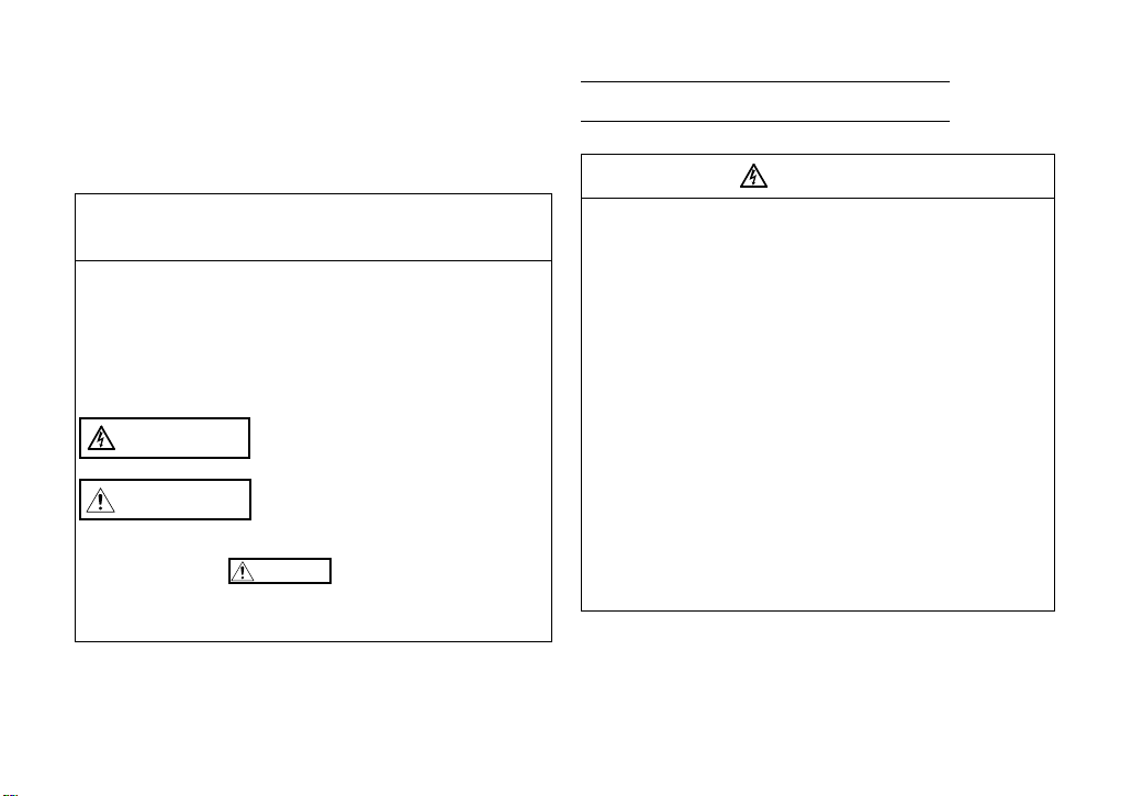
1.2.1 Packing confirmation
Check the enclosed items.
Plug-in option
......................................... 1
Mounting screw (M3 × 6mm)
.............. 2 (Refer to page 8.)
PRE-OPERATION INSTRUCTIONS
Hex-head screw for option
mounting (5.5mm)
............... 1 (Refer to page 8.)
O
1
F
2
F
4
4
5
5
3
3
6
6
2
2
7
7
1
1
8
8
0
0
9
9
F
F
A
A
E
E
B
B
D
D
C
C
Communication option LED
display cover
.............. 1 (Refer to page 7.)
PROFIBUS
5.5mm
is a registered trademark of PROFIBUS User Organization.
1
3
0
F
E
D
C
B
A
9
8
7
6
5
4
3
2
1
0
F
E
D
C
B
A
9
8
7
6
5
4
3
2
1
1
O
F
F
2
SW2
SW3
SW1
X1
X16
D+
DVD-
CNTR
FG
V+
D+
D-
D+
V-
FG
PRE-OPERATION INSTRUCTIONS
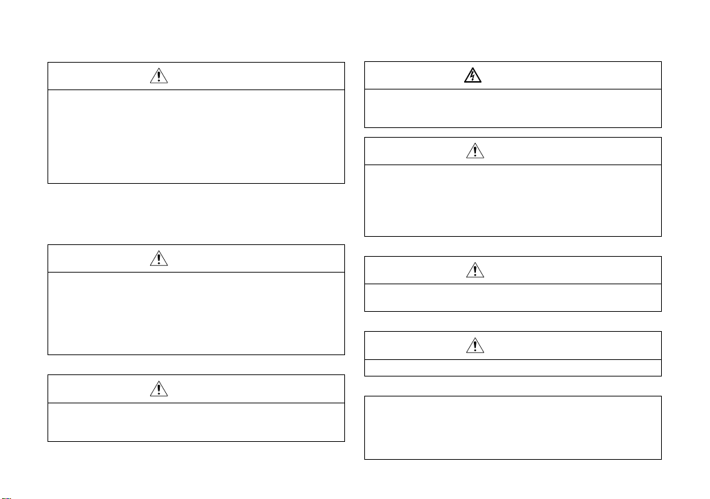
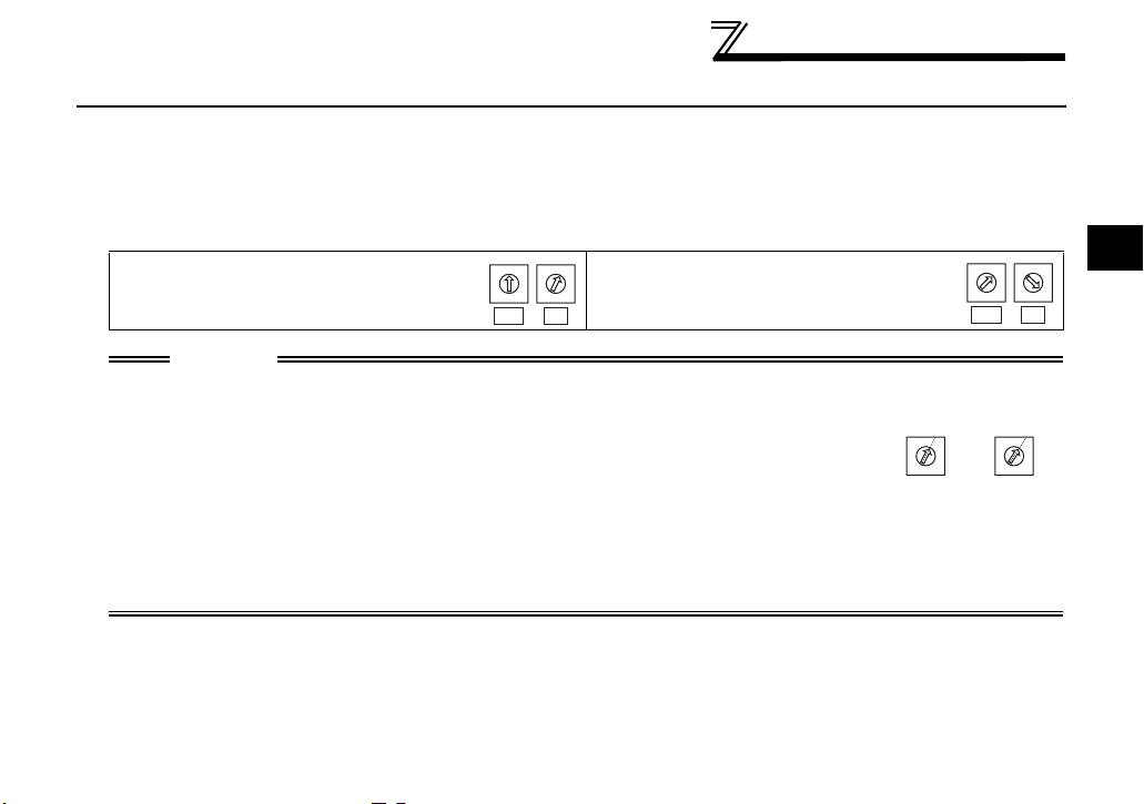
1.2.2 Parts
Switch for manufacturer setting
O
Terminal block
Connect
the communication
(Refer to page 10.)
cable.
1
Do not change from
F
2
F
initially-set status (1, 2:OFF).
Front view Rear view
FR-A7NP
SW2
O
1
F
2
F
SW1
SW3
5
5
4
4
6
6
3
3
7
7
2
2
8
8
1
1
9
9
0
0
A
A
F
F
B
B
E
E
C
C
D
D
X1X16
Mounting hole
Node address switch
Mount on the inverter with an accessory mounting screw.
Terminal
layout
4
LED1
(Refer to page 7.)
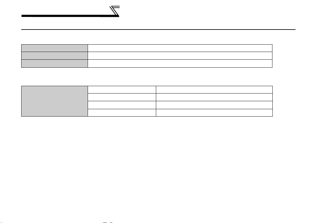
Name Function
Node address
switch
Operation status
indication LED
Operation status indication LED
Lit/off of the LED indicate inverter operation status.
Mounting
STATUS
hole
(Refer to page 5.)
Connector
Connect to the inverter option connector.
Set the inverter address within the range of 0H to 7DH.
Off
Red is lit
Green is lit
Inverter power off
A communication error with the master occurred
During communication with the master
Mounting hole
PRE-OPERATION INSTRUCTIONS
1.3 Node Address Setting
•Setting with node address switch
Set the node address between "0H to 7DH" using node address switches on the FR-A7NP (refer to page 4).
The setting is reflected at the next power-on or inverter reset.
Set the arrow (×) of the corresponding switches to the number and alphabet to set a desired address.
•Setting example
Node address 1:
Set the "
"
× " of x16(SW3) to "0" and the
× " of x1(SW1) to "1".
0
1
F
2
E
3
D
4
5
C
B
6
7
A
8
9
X16 X1
CAUTION
1. Set the node address switch to the switch number (alphabet) position correctly.
If the switch is set between numbers, normal data communication can not be
made.
2. Do not set the node address to 7E
3. Depending on the master module, 0
be used.
4. You cannot set the same node address to other devices on the network. (Doing so disables proper
communication.)
5. Set the inverter node address before switching on the inverter and do not change the setting while
power is on. Otherwise you may get an electric shock.
H through FFH.
H, 1H, 2H, 7CH, 7DH of node address may not
Node address 26:
0
1
F
2
E
3
D
4
5
C
B
6
7
A
8
9
Set the "
"
× " of x1(SW1) to "1".
×" of x16(SW3) to "2" and the
Good
example
0
F
E
D
C
B
A
9
X16 X1
example
1
0
F
2
E
3
D
4
5
C
B
6
7
A
8
9
1
2
3
4
5
6
7
8
Bad
0
F
E
D
C
B
A
9
1
0
F
2
E
3
D
4
5
C
B
6
7
A
8
9
1
1
2
3
4
5
6
7
8
5
PRE-OPERATION INSTRUCTIONS
1.4 Specifications
1.4.1 Inverter option specifications
Type Inverter plug-in option type
Number of nodes occupied One inverter occupies one node.
Connection cable Cable which supports 12.0Mbps communication (EEIA-485(RS-485) standard)
1.4.2 Communication specifications
Wiring length 1200m or less 9600bps, 19.2Kbps, 93.75Kbps
Communication speed
Wiring length 600m or less 187.5Kbps
Wiring length 200m or less 500Kbps, 1.5Mbps
Wiring length 100m or less 3.0Mbps, 6.0Mbps, 12.0Mbps
6
2 INSTALLATION
2.1 Pre-Installation Instructions
Make sure that the input power of the inverter is off.
CAUTION
With input power on, do not install or remove the plug-in option. Otherwise, the inverter and
plug-in option may be damaged.
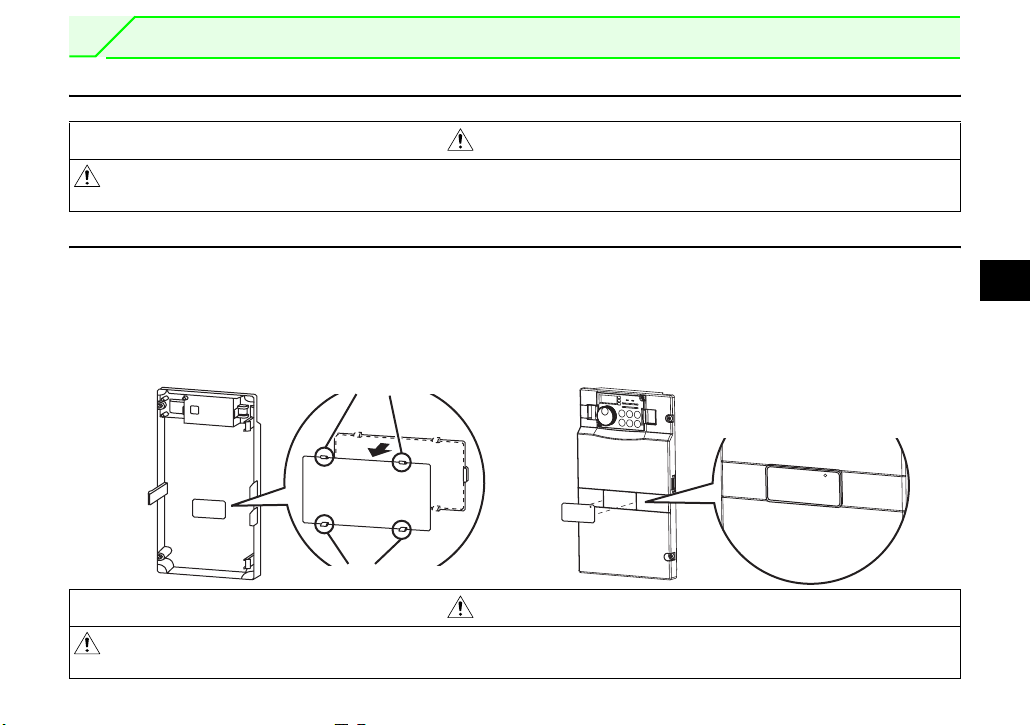
2.2 Installation of the Communication Option LED Display Cover
Mount the cover for displaying the operation status indication LED for the communication option on the
inverter front cover.
2
1)Cut off hooks on the rear of the inverter front
cover with nipper, etc. and open a window for
fitting the LED display cover.
Cut off with a nipper, etc.
2)Fit the communication option LED display
cover to the front of the inverter front cover
and push it into until fixed with hooks.
Fit it so that the position of
lenses is in the upper-right
of the LED display cover.
Fitting drawing
Cut off with a nipper, etc.
CAUTION
Take care not to hurt your hand and such with portions left by cutting hooks of the rear of the
front cover.
7
INSTALLATION
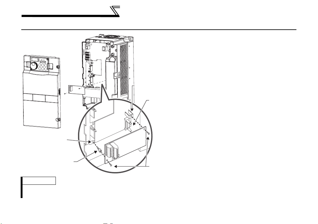
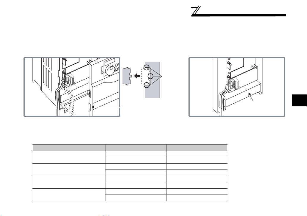
2.3 Installation Procedure
1) Remove the inverter front cover.
1)
2) Mount the hex-head screw for option
mounting into the inverter screw hole (on
earth plate). (size 5.5mm, tightening
torque 0.56N⋅m to 0.75N⋅m)
Screw hole for
option mounting
Inverter side
option
connector
3) Securely fit the connector of the plug-in
option to the inverter connector along the
guides.
4) Securely fix the both right and left sides
of the plug-in option to the inverter with
Screw hole for
option mounting
(on earth plate)
Hex-head screw
for option mounting
2)
3)
1
0
2
9
3
8
4
7
5
6
1
0
2
9
3
8
4
7
5
6
4) Mounting
screws
the accessory mounting screws. If the
screw holes do not line-up, the connector
may not have been plugged snugly.
Check for loose plugging.
REMARKS
After removing two screws on the right and left places, remove the plug-in option.
(The plug-in option is easily removed if thecontrol circuit terminal block is removed before.)
8
INSTALLATION
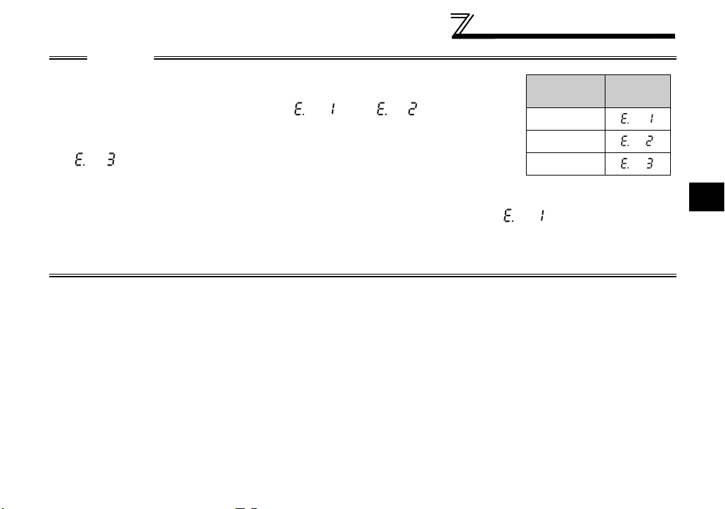
CAUTION
• When using the FR-A7NP with the FR-A700 series inverter, mount it in the
"option connector 3 (lowermost connector)" of the inverter.
If it is fitted in option connector 1 or 2, " " or " " (option alarm)
is displayed and the inverter will not function. In addition, when the inverter can
not recognize that the option is mounted due to improper installation, etc.,
" " (option alarm) is displayed even if the option is fitted in the option
connector 3.
• The FR-F700 series has one connection connector for the plug-in option. When the inverter can not
recognize that the option unit is mounted due to improper installation, etc., " " (option alarm) is
displayed.
• Take care not to drop a hex-head screw for option mounting or mounting screw during mounting and removal.
• Pull out the option straight to remove. Otherwise, the connector may be damaged by some applied force.
Mounting
Position
Connector 1
Connector 2
Connector 3
Error
Display
2
9
3 WIRING
A
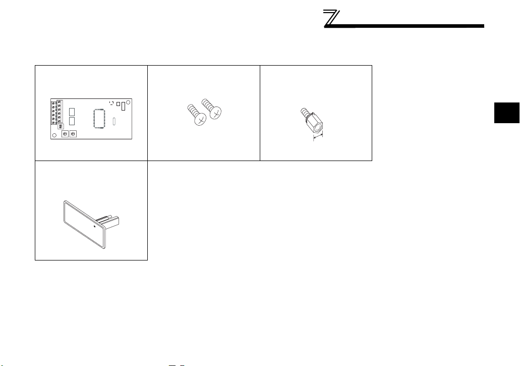
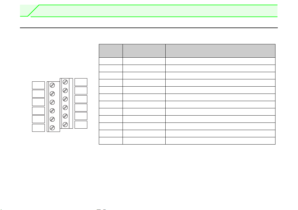
3.1 Terminal Block
Terminal block layout
10
B
1
2
3
4
5
CNTR
6
D+
D-
V-
D-
FG
Ter minal
No.
1-A V+ (VP)*1 Voltage output (approx. 5V to V-)
1-B D+ (RXD/TXD-P) Send and receive profibus signal+
2-A D+ (RXD/TXD-P) Send and receive profibus signal+
V+
1
2
D+
D-
3
D+
4
V-
5
FG
6
2-B D+ (RXD/TXD-N) Send and receive profibus signal-
3-A D+ (RXD/TXD-N) Send and receive profibus signal-
3-B V- (DGND)*1 GND of D+/D-
4-A D+ (RXD/TXD-P) Send and receive profibus signal+
4-B D+ (RXD/TXD-N) Send and receive profibus signal-
5-A V- (DGND)*1 GND of D+/D-
5-B CNTR *2 Control signal (sending request from the inverter)
6-A FG (connected to the earth of the inverter unit)
6-B FG (connected to the earth of the inverter unit)
*1 Use when selecting a terminating resistor.
*2 It may not be necessary depending on the master used.
Ter m i n al Nam e Definition
WIRING
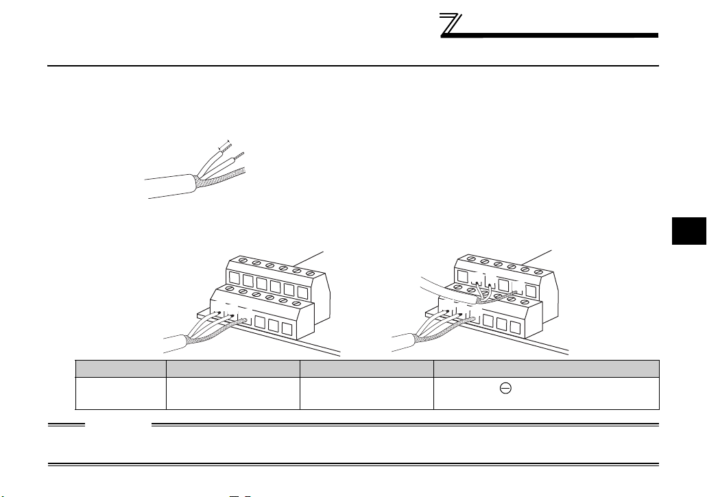
3.2 Wiring
Use the network connection cable which supports 12.0Mbps communication.
(1) Strip off the sheath of the PROFIBUS communication dedicated cable and wind wires and shield cables
to use. If the length of the sheath pealed is too long, a short circuit may occur among neighboring wires.
If the length is too short, cables and shield cables might come off.
Cable stripping size
(2) Loosen the terminal screw and insert the cable into the terminal.
Tighten each cable with fixing screws to the recommended tightening torque.
<Cable connection example>
Approx 5mm
Wire the stripped cable after twisting it to prevent it from
becoming loose.
In addition, do not solder it.
Use a bar type terminal as required.
<Connection example of multiple inverters>
3
To next inverter
D+
D-
V-
To master
D+
D-
V-
D+
D-
V-
Screw Size Tightening Torque Cable Size Screwdriver
M2 0.22N•m to 0.25N•m
0.3mm
2
to 0.75mm
2
Small flat-blade screwdriver
(Tip thickness: 0.4mm /tip width: 2.5mm)
CAUTION
Undertightening can cause cable disconnection or malfunction. Overtightening can cause a short circuit or
malfunction due to damage to the screw or unit.
11
WIRING
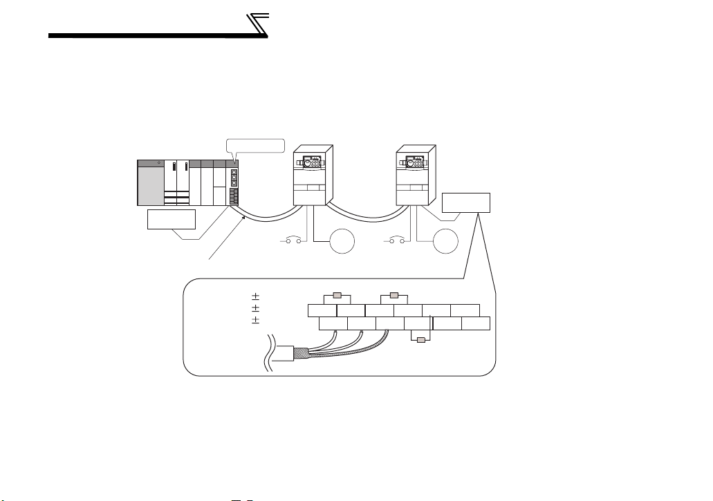
(3) Terminating resistor
If the node at both ends of the network are the FR-A7NP and inverter, connect a connector with a
built-in terminating resistor.
Connection example
12
Master station
PLC etc.
Terminating
resistor
Power
supply
Profibus communication cable
R1=390Ω 2% 1/4W
R2=220Ω 2% 1/4W
R3=390Ω 2% 1/4W
To other inverter
(node)
Inverter
Power
Motor Motor
supply
R1 R2
V+D+D+D-D-V-D+D-V-
Inverter
R3
Terminating
resistor
CNTRFGFG
WIRING
(4) For wiring of the FR-A700 series 22K* or less and the FR-F700 series 30K* or less, route wires between
the control circuit terminal block and front cover. If cables can not be routed between the control circuit
terminal block and front cover (approx 7mm), remove a hook of the front cover and use a space become
available.
For wiring of the FR-A700 series 30K* or more and the FR-F700 series 37K* or more, use the space
on the left side of the control circuit terminal block.
Cut off
1
0
2
9
3
8
4
1
7
5
0
2
6
9
3
8
4
7
5
6
with a
nipper,
etc.
1
0
2
9
3
8
4
1
7
5
0
2
6
9
3
8
4
7
5
6
FR-A700 series 22K or less
and FR-F700 series 30K or less
Cut off a hook on the inverter
front cover side surface.
(Cut off so that no portion is left.)
FR-A700 series 30K or more
and FR-F700 series 37K or more
Control circuit
terminal block
* The inverter type of 22K and 30K of FR-A700 series, 30K and 37K of FR-F700 series in each -NA, -EC versions are as follows.
NA EC
FR-A700 series 22K
(FR-A720-22K, FR-A740-22K)
FR-A700 series 30K
(FR-A720-30K, FR-A740-30K)
FR-F700 series 30K
(FR-F720-30K, FR-F740-30K)
FR-F700 series 37K
(FR-F720-37K, FR-F740-37K)
FR-A720-00900-NA
FR-A740-00440-NA FR-A740-00620-EC
FR-A720-01150-NA
FR-A740-00570-NA FR-A740-00770-EC
FR-F720-01250-NA
FR-F740-00620-NA FR-F740-00620-EC
FR-F720-01540-NA
FR-F740-00770-NA FR-F740-00770-EC
3
13
WIRING
C
REMARKS
⋅ When the hook of the inverter front cover is cut off for wiring, the protective structure (JEM1030) changes to open
type (IP00).
AUTION
When performing wiring using the space between the inverter front cover and control circuit
terminal block, take care not to subject the cable to stress.
After wiring, wire offcuts must not be left in the inverter. They may cause an error, failure or
malfunction.
14

4 INVERTER SETTING
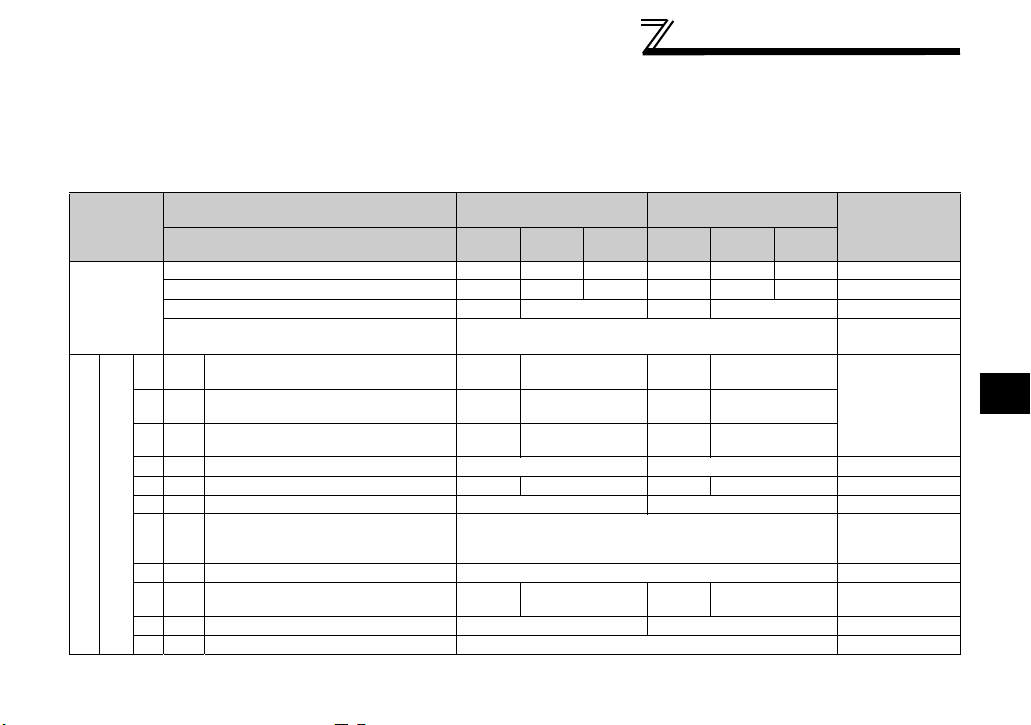
4.1 Parameter List
The following parameters are used for the communication option (FR-A7NP)
Set the values according to need.
Parameter
Number
79 Operation mode selection 0 to 4, 6, 7 1 0 17
338
339
340
342
349
*1 Communication reset selection 0, 1 1 0 32
*1
500
501
*1
502
*1
550
*1 Parameters which can be displayed when the plug-in option (FR-A7NP) is mounted.
Communication operation
command source
Communication speed
command source
Communication startup mode
selection
Communication EEPROM write
selection
Communication error execution
waiting time
Communication error
occurrence count display
Stop mode selection at
communication error
NET mode control source
selection
Name Setting Range
0, 1 1 0 20
0, 1, 2 1 0 20
0, 1, 2, 10, 12 1 0 17
0, 1 1 0 24
0 to 999.8s 0.1s 0 25
01026
0, 1, 2, 3 1 0 27
0, 1, 9999 1 9999 20
Minimum
Setting
Increments
Initial
Value
Refer to page
4
15

INVERTER SETTING
4.2 Operation Mode Setting
The inverter mounted with a communication option has three operation modes.
(1) PU operation [PU]..............Controls the inverter from the key of the operation panel (FR-DU07)
mounted on the inverter.
(2) External operation [EXT] ... Controls the inverter by switching on/off external signals connected to the
control circuit terminals of the inverter.
(The inverter is factory-set to this mode.)
(3) Network operation [NET] ... Controls the inverter with instructions from the network via the
communication option.
(The operation signal and running frequency can be entered from the
control circuit terminals depending on the Pr. 338 Communication operation
command source and Pr. 339 Communication speed command source setting.
Refer to page 21.)
4.2.1 Operation mode indication
FR-DU07
Operation mode indication
(The inverter operates according to the LED lit mode.)
PU: PU operation mode
EXT: External operation mode
NET: Network operation mode
16

INVERTER SETTING
4.2.2
(1) Operation mode switching conditions
Before switching the operation mode, check that:
1) The inverter is at a stop;
2) Both the STF and STR signals are off; and
3) The Pr. 79 Operation mode selection setting is correct.
(Set with the operation panel of the inverter.)
Refer to the inverter manual (applied) for details of Pr. 79.
(2) Operation mode selection at power on and at restoration from instantaneous power failure
The operation mode at power on and at restoration from instantaneous power failure can be selected.
Set a value other than "0" in Pr. 340 to select the network operation mode.
After started in network operation mode, parameter write from the network is enabled.
REMARKS
1. Change of the Pr. 340 setting is made valid when powering on or resetting the inverter.
2. Pr. 340 can be changed with the operation panel independently of the operation mode.
Operation mode switching and communication startup mode (Pr. 79, Pr. 340)
4
17
INVERTER SETTING
Pr. 340
Setting
(initial
value)
1, 2 *2
10, 12
*1 Operation mode can not be directly changed between the PU operation mode and network operation mode.
*2 The Pr. 340 settings "2, 12" are mainly used for communication operation using the inverter RS-485 terminal.
When a value other than "9999" (selection of automatic restart after instantaneous power failure) is set in Pr. 57 Restart coasting time, the
inverter will resume the same operation state which was in before after power has been restored from an instantaneous power failure. When
Pr.340 = "1, 10", run command from communication turns off after instantaneous power failure.
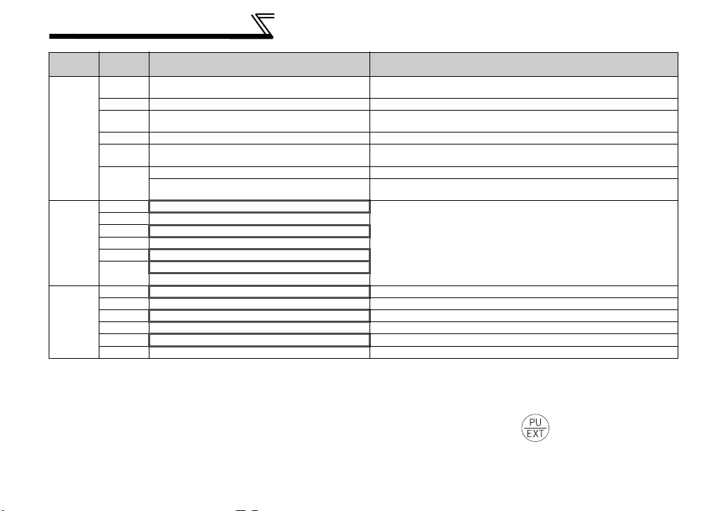
Pr. 79
Setting
0 (initial
value)
1 PU operation mode PU operation mode fixed
0
2 External operation mode
3, 4 External/PU combined operation mode Operation mode switching is disallowed
6 External operation mode
7
0 NET operation mode
1 PU operation mode
2 NET operation mode
3, 4 External/PU combined operation mode
6
7
0 NET operation mode Switching between the PU and NET operation mode is enabled *3
1 PU operation mode Same as when Pr. 340 = "0"
2 NET operation mode NET operation mode fixed
*2
3, 4 External/PU combined operation mode Same as when Pr. 340 = "0"
6
7 External operation mode Same as when Pr. 340 = "0"
Operation Mode at Power on or Power
External operation mode
X12 (MRS) signal ON..... external operation mode Switching among the external, PU, and NET operation mode is enabled
X12 (MRS) signal OFF ... external operation mode
*4 NET operation mode
X12 (MRS) signal ON .... NET operation mode
X12 (MRS) signal OFF ... external operation mode
*4 NET operation mode
Restoration
Switching among the external, PU, and NET operation mode is
enabled
*1
Switching between the external and Net operation mode is enabled
Switching to the PU operation mode is disallowed
Switching among the external, PU, and NET operation mode is enabled
while running.
External operation mode fixed (Forcibly switched to external
operation mode.)
Same as when Pr. 340 = "0"
Switching between the PU and NET operation mode is enabled while running
Operation Mode Switchover
*3 Operation mode can be changed between the PU operation mode and network operation mode with of the operation panel (FR-
DU07) and X65 signal.
*4 Pr. 79 = "6" and Pr. 128 to Pr. 134 (PID control) are not activated simultaneously. Switchover mode and PID control are made invalid, and
the inverter performs the same operation as when "0" is set in Pr. 79.
*1
*3
18
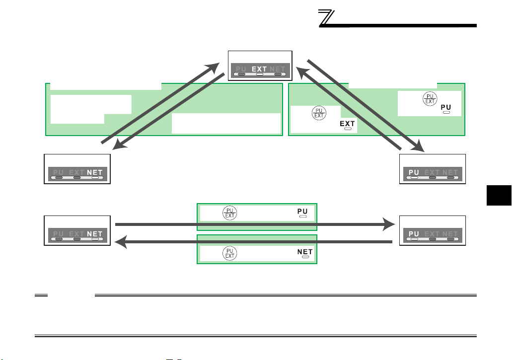
(3) Operation mode switching method
INVERTER SETTING
When "0, 1, or 2" is set in Pr. 340
Switching from the network
Switch to the external
operation mode from
the network.
Network operation PU operation
Switch to the network operation
mode from the network.
When "10 or 12" is set in Pr. 340
Network operation PU operation
For the switching method from the external terminal, refer to the inverter manual (applied).
Refer to page 54 and 77 for a switching method from the network.
External operation
Press of
the PU to light .
Press of of the PU to light .
Press of of the PU to light .
Switching from the PU
Press of the
PU to light .
CAUTION
⋅ When starting the inverter in network operation mode at powering on or an inverter reset, set a value other than 0 in
Pr. 340. (Refer to page 17)
⋅ When setting a value other than 0 in Pr. 340, make sure that the initial settings of the inverter are correct.
4
19

INVERTER SETTING
4.3 Operation and Speed Command Source (Pr. 338, Pr. 339, Pr. 550)
(1) Select control source for the network operation mode (Pr. 550)
A control location for the network operation mode can be selected from either the inverter RS-485
terminal or communication option.
When using a communication option, set "0 or 9999 (initial value)" in Pr. 550.
Parameter
Number
550
NET mode operation
command source selection
Name Initial Value
Refer to the inverter manual (applied) for details.
9999
Setting
Range
0
1
9999
Description
Control source of the communication
option is valid
(control source of the inverter RS-485
terminal is invalid)
Control source of the inverter RS-485
terminal is valid
(control source of the communication
option is invalid)
Automatic recognition of the
communication option
Normally, control source of the RS485 terminal is valid. When a
communication option is mounted,
the control source of the
communication option is valid.
20
INVERTER SETTING
(2) Selection of control source for the network operation mode (Pr. 338, Pr. 339)
⋅ As control sources, there are operation command source that controls signals related to the start
command and function selection of the inverter and speed command source that controls signals
related to frequency setting.
⋅ In network operation mode, commands from the external terminals and communication are as listed
below.
Control
Location
Selection
Fixed
functions
(Functions
equivalent
to
terminals)
Selective functions
Pr. 178 to Pr. 189 settings
Pr. 338 Communication operation
command source
Pr. 339 Communication speed
Running frequency from communication NET NET NET NET
Terminal 2 External External
Terminal 4 External External
Terminal 1 Compensation
0RL
1RM
2RH
3 RT Second function selection NET External
4 AU Terminal 4 input selection Combined Combined
5 JOG Jog operation selection External
6CS
7 OH External thermal relay input External
8 REX 15-speed selection NET External NET External
9 X9 Third function *1 NET External
10 X10 Inverter operation enable signal External
command source
Low-speed operation command/
remote setting clear
Middle-speed operation command/
remote setting deceleration
High-speed operation command/
remote setting acceleration
Automatic restart after
instantaneous power failure
selection
0:NET
0:NET 1:External
1:
External2:External
NET External NET External
NET External NET External
NET External NET External
0:NET
External
1:
External2:External
Pr. 59 = "0"
(multi-speed)
Pr. 59 = "1, 2"
Pr. 59 = "0"
(multi-speed)
Remarks
4
(remote)
21
 Loading...