

Mitsubishi Electric FR-A7ND E kit Instruction Manual

INVERTER
Plug-in option
FR-A7ND E kit
INSTRUCTION MANUAL
communication function
PRE-OPERATION INSTRUCTIONS
1
INSTALLATION
2
WIRING
3
INVERTER SETTING
4
FUNCTIONS
5
OBJECT MAP DEFINITIONS
6
OBJECT MAP
7
TROUBLESHOOTING
8
Thank you for choosing this Mitsubishi Inverter plug-in option.
This Instruction Manual gives handling information and
precautions for use of this equipment. Incorrect handling might
cause an unexpected fault. Before using the equipment, please
read this manual carefully to use the equipment to its optimum.
Please forward this manual to the end user.
This section is specifically about
safety matters
Do not attempt to install, operate, maintain or inspect this
product until you have read through this Instruction Manual and
appended documents carefully and can use the equipment
correctly. Do not use this product until you have a full
knowledge of the equipment, safety information and
instructions.
In this Instruction Manual, the safety instruction levels are
classified into "WARNING" and "CAUTION".
Incorrect handling may cause
WARNING
CAUTION
The level may even lead to a serious
consequence according to conditions. Both instruction levels
must be followed because these are important to personal
safety.
CAUTION
hazardous conditions, resulting in
death or severe injury.
Incorrect handling may cause
hazardous conditions, resulting in
medium or slight injury, or may
cause only material damage.
SAFETY INSTRUCTIONS
1. Electric Shock Prevention
WARNING
• While the inverter power is ON, do not open the front cover or
the wiring cover. Do not run the inverter with the front cover
or the wiring cover removed. Otherwise you may access the
exposed high voltage terminals or the charging part of the
circuitry and get an electric shock.
• Even if power is OFF, do not remove the front cover except for
wiring or periodic inspection. You may accidentally touch the
charged inverter circuits and get an electric shock.
• Before wiring or inspection, power must be switched OFF. To
confirm that, LED indication of the operation panel must be
checked. (It must be OFF.) Any person who is involved in
wiring or inspection shall wait for at least 10 minutes after the
power supply has been switched OFF and check that there
are no residual voltage using a tester or the like. The
capacitor is charged with high voltage for some time after
power OFF, and it is dangerous.
• Any person who is involved in wiring or inspection of this
equipment shall be fully competent to do the work.
• The plug-in option must be installed before wiring. Otherwise,
you may get an electric shock or be injured.
• Do not touch the plug-in option or handle the cables with wet
hands. Otherwise you may get an electric shock.
• Do not subject the cables to scratches, excessive stress,
heavy loads or pinching. Otherwise you may get an electric
shock.
A-1
2. Injury Prevention
3) Usage
CAUTION
• The voltage applied to each terminal must be the ones
specified in the Instruction Manual. Otherwise burst, damage,
etc. may occur.
• The cables must be connected to the correct terminals.
Otherwise burst, damage, etc. may occur.
• Polarity must be correct. Otherwise burst, damage, etc. may
occur.
• While power is ON or for some time after power-OFF, do not
touch the inverter as they will be extremely hot. Doing so can
cause burns.
3. Additional Instructions
Also the following points must be noted to prevent an accidental
failure, injury, electric shock, etc.
1) Transportation and mounting
CAUTION
• Do not install or operate the plug-in option if it is damaged or
has parts missing.
• Do not stand or rest heavy objects on the product.
• The mounting orientation must be correct.
• Foreign conductive objects must be prevented from entering
the inverter. That includes screws and metal fragments or
other flammable substances such as oil.
2) Trial run
CAUTION
• Before starting operation, each parameter must be confirmed
and adjusted. A failure to do so may cause some machines to
make unexpected motions.
WARNING
• Do not modify the equipment.
• Do not perform parts removal which is not instructed in this
manual. Doing so may lead to fault or damage of the inverter.
CAUTION
•
When parameter clear or all parameter clear is performed, the
required parameters must be set again before starting operations
because all parameters return to the initial value.
• Static electricity in your body must be discharged before you
touch the product. Otherwise the product may be damaged.
4) Maintenance, inspection and parts replacement
CAUTION
• Do not test the equipment with a megger (measure insulation
resistance).
5) Disposal
CAUTION
• This inverter plug-in option must be treated as industrial
waste.
6) General instruction
Many of the diagrams and drawings in this Instruction Manual
show the inverter without a cover or partially open for
explanation. Never operate the inverter in this manner. The
cover must be reinstalled and the instructions in the inverter
manual must be followed when operating the inverter.
A-2

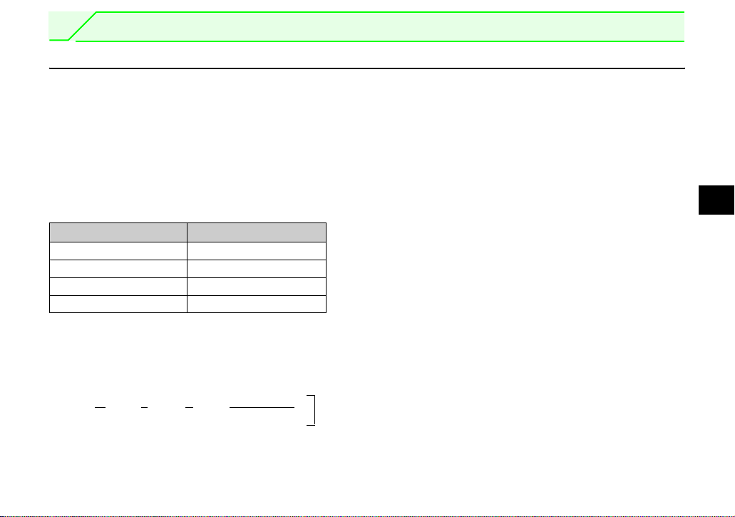
⎯ CONTENTS ⎯
1 PRE-OPERATION INSTRUCTIONS 1
1.1 Unpacking and Product Confirmation .............................................................................................1
1.1.1 SERIAL number..............................................................................................................................................1
1.1.2 Product confirmation.......................................................................................................................................2
1.2 Parts ....................................................................................................................................................3
1.3 MNS LED (operation status indication) ...........................................................................................4
1.4 Specifications.....................................................................................................................................5
2 INSTALLATION 6
2.1 Pre-Installation Instructions .............................................................................................................6
2.2 Installation Procedure .......................................................................................................................6
2.3 Node Address Setting .....................................................................................................................12
3 WIRING 14
3.1 Connection to Network....................................................................................................................14
3.2 Wiring................................................................................................................................................15
4 INVERTER SETTING 20
4.1 Parameter List ..................................................................................................................................20
4.2 DeviceNet Data .................................................................................................................................21
I

4.2.1 DeviceNet address (Pr. 345)........................................................................................................................22
4.2.2 DeviceNet baud rate (Pr. 346)......................................................................................................................23
4.3 Operation Mode Setting ..................................................................................................................25
4.3.1 Operation mode indication............................................................................................................................25
4.3.2 Operation mode switching and communication startup mode (Pr. 79, Pr. 340)...........................................26
4.4 Operation and Speed Command Source (Pr. 338, Pr. 339, Pr. 550) ............................................29
4.4.1 Communication EEPROM write selection (Pr. 342).....................................................................................33
4.5 Operation at Communication Error Occurrence...........................................................................34
4.5.1 Operation selection at communication error occurrence (Pr. 500 to Pr. 502) ..............................................34
4.5.2 Alarm and measures ....................................................................................................................................38
4.6 Inverter Reset ...................................................................................................................................40
4.7 Frequency and Speed Conversion Specifications .......................................................................42
5 FUNCTIONS 43
5.1 Output from the Inverter to the Network........................................................................................43
5.2 Input to the Inverter from the Network...........................................................................................43
6 OBJECT MAP DEFINITIONS 44
6.1 Object Model of DeviceNet Communication .................................................................................44
6.2 Response Level................................................................................................................................45
6.2.1 Response level of Polling I/O .......................................................................................................................45
6.2.2 Response level of explicit message .............................................................................................................46
6.3 Recommendation for Software Developers ..................................................................................47
II

7OBJECT MAP 48
7.1 Class 0x01 (Identity-Object) ............................................................................................................48
7.1.1 Class 0x01 Instance 0 ..................................................................................................................................48
7.1.2 Class 0x01 Instance 1 ..................................................................................................................................49
7.2 Class 0x03 (DeviceNet Object) .......................................................................................................50
7.2.1 Class 0x03 Instance 1 ..................................................................................................................................50
7.3 Class 0x04 (Assembly Object) ........................................................................................................51
7.3.1 Output Instance 20/Input Instance 70...........................................................................................................52
7.3.2 Output Instance 21/Input Instance 71...........................................................................................................54
7.3.3 Output Instance 126/Input Instance 176.......................................................................................................56
7.4 Class 0x05 (DeviceNet Connection Object)...................................................................................60
7.4.1 Class 0x05 Instance 1 Attribute (Explicit message connection)..................................................................60
7.4.2 Class 0x05 Instance 2 Attribute (Polling I/O connection) .............................................................................62
7.4.3 Class 0x05 Instance 4, 5, 6 Attribute (Explicit message connection)..........................................................65
7.4.4 Class 0x05 Instance 1, 2, 4, 5, 6 service......................................................................................................66
7.5 Class 0x28 (Motor Data Object) ......................................................................................................67
7.5.1 Class 0x28 Instance 1 ..................................................................................................................................67
7.6 Class 0x29 (Control Supervisor Object) ........................................................................................68
7.6.1 Class 0x29 Instance 1 ..................................................................................................................................68
7.7 Class 0x2A (AC Drive Object) .........................................................................................................70
7.7.1 Class 0x2A Instance 1..................................................................................................................................70
7.8 Class 0x66 (Extended Object I).......................................................................................................79
7.8.1 Class 0x66 Instance 1 ..................................................................................................................................79
7.9 Class 0x67 (Extended Object II)......................................................................................................84
III

7.9.1 Class 0x67 Instance 1 ..................................................................................................................................84
7.10 Class 0x70 to 0x79 (Extended Object III) .......................................................................................86
7.10.1 Class 0x70 to 0x79 Instance 1, 2 .................................................................................................................86
7.11 Class 0x80 (Extended Object IV) ....................................................................................................87
7.11.1 Class 0x80 Instance 1 ..................................................................................................................................87
7.12 FR-E5ND (FR-E500-KND) Compatible Mode..................................................................................89
8 TROUBLESHOOTING 92
APPENDIX 93
EDS File ............................................................................................................................................93
Error Code List.................................................................................................................................94
IV
1 PRE-OPERATION INSTRUCTIONS
1.1 Unpacking and Product Confirmation
Take the plug-in option out of the package, check the product name, and confirm that the product is as you
ordered and intact.
This product is a plug-in option for the FR-E700 series inverter.
1.1.1 SERIAL number
Check the SERIAL number indicated on the rating plate or package.
For the 200V class of FR-E700, this option can be used with the inverter having the following SERIAL
number or later. (For the 400V class of FR-E700, this option can be used with all inverters regardless of
SERIAL number.)
Type SERIAL number
FR-E720-0.1K to 0.75K J7Y{{{{{{
FR-E720-1.5K to 5.5K K7Y{{{{{{
FR-E720-7.5K L7Y{{{{{{
FR-E720-11K, 15K G7Y{{{{{{
z
SERIAL number check
Refer to the Instruction Manual of the inverter for the location of the rating plate.
Rating plate example
Symbol Year Month Control number
The SERIAL consists of one symbol, two characters indicating production year and month,
and six characters indicating control number.
The last digit of the production year is indicated as the Year, and the Month is indicated by
1 to 9, X (October), Y (November), or Z (December).
7 Y {{{{{{
SERIAL (Serial No.)
1
1
PRE-OPERATION INSTRUCTIONS
1.1.2 Product confirmation
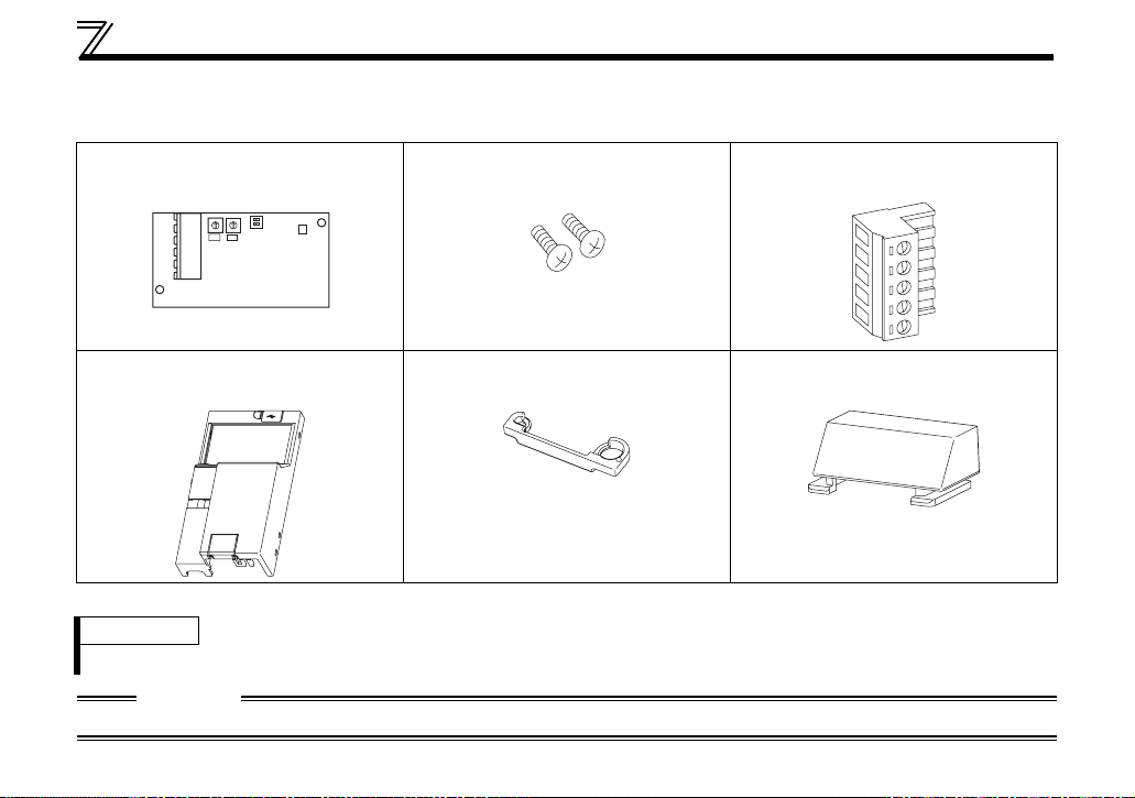
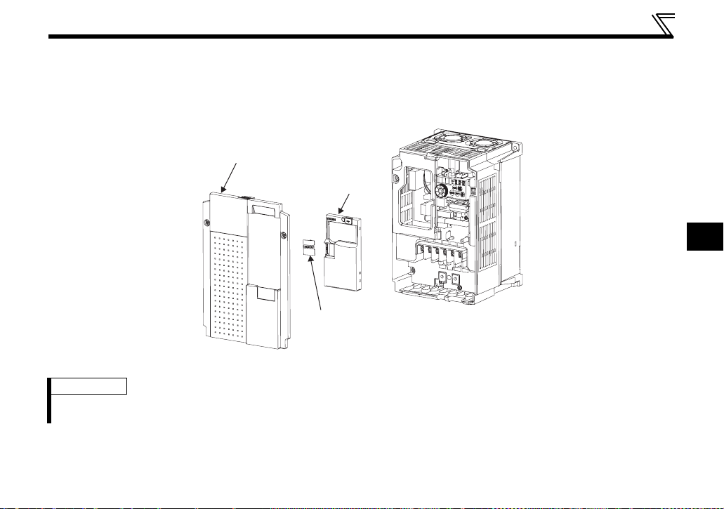
Check the enclosed items.
Plug-in option
.........................................................1
0
0
1
1
9
9
2
2
8
8
3
3
7
7
4
4
6
6
5
5
X10 X1
Mounting screw (M3 × 6mm)
........................ 2 (Refer to page 8, 10.)
Terminal block
......................... 1 (Refer to page 8, 10.)
Front cover for plug-in option
.........................................................1
Option protective cover
....................................................... 1*
Option small cover (Not used)
......................................................... 1
* Used with the FR-E720-3.7K (FR-E720-175) or less and FR-E740-7.5K (FR-E740-170) or less.
REMARKS
• DeviceNetTM is a registered trademark of ODVA (Open DeviceNet Vender Association, INC).
CAUTION
• In place of the inverter front cover, install a provided front cover for plug-in option.
2
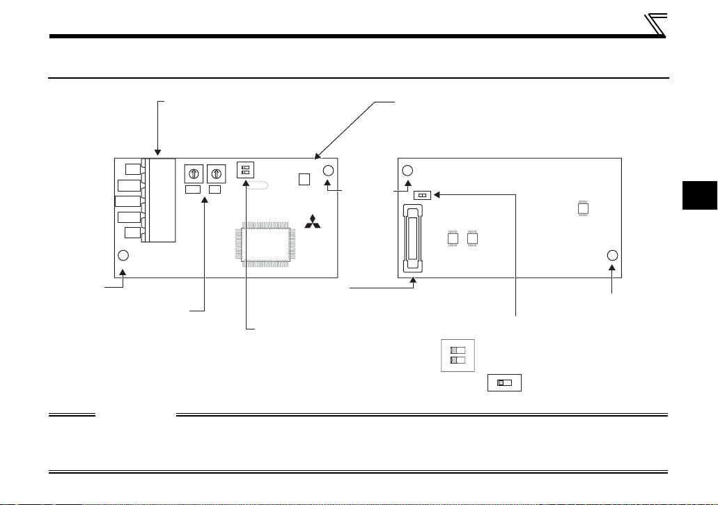
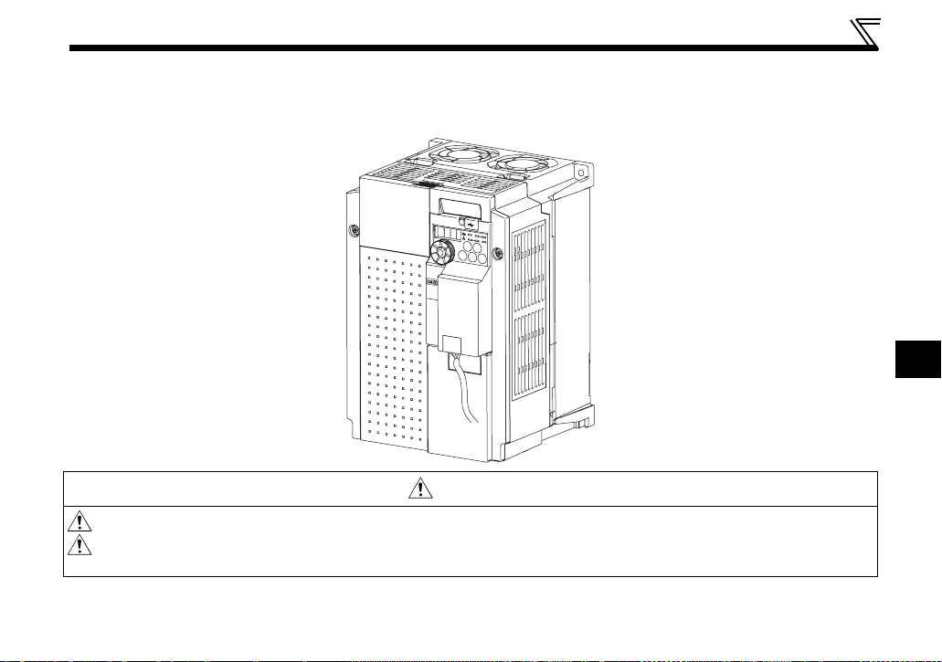
1.2 Parts
PRE-OPERATION INSTRUCTIONS
Connector for communication
Mount the accessory terminal
block to connect to the network.
MNS LED (operation status indication)
Lit/flicker/off of the LED indicate inverter
operation status.
(Refer to page 4.)
Front view Rear view
ON
0
1
X10 X1
SW1
9
8
7
6
5
V-
CAN-
SHIELD
CAN+
V+
Mounting
hole
Node address switch
Set the node address.
(Refer to page 12.)
CAUTION
• Set the compatible mode switch (SW3) before switching ON the inverter and do not change the setting
while the power is ON. Otherwise you may get an electric shock.
• Do not turn ON the switch 2 of the compatible mode switch (SW3).
12
0
1
9
2
2
8
3
3
7
4
6
5
SW3
4
SW2
LED1
2
1
MNS
FR-A7ND
Mounting
hole
SW4
Connector
Connect to the inverter
option connector.
Compatible mode switch (
SW3)
Switch over to the FR-E5ND
(FR-E500-KND) compatible mode.
(Refer to page 89.)
(In the initial status, the switches
1 and 2 are both OFF.)
12
Switch for manufacturer setting
Do not change from initially-set
ON
status (OFF).
SW4
2
L
O
N
Mounting hole
1
3

PRE-OPERATION INSTRUCTIONS
1.3 MNS LED (operation status indication)
The MNS LED indicates the operating status of the option unit by its indication status.
Check the position of LED on page 3.
LED
Indication
Off
Green
(flickering)
Green (lit)
Red (flickering) Connection time-out
Red (lit) Critical link failure
* Time limit = 4 × EPR (EPR = Expected Pack Rate Class 0x05 Instance 1 Attribute 9 (refer to page 61))
Operating Status Note
Inverter power off
Network power off
Own node only on the network
Network and inverter power on
Connection not yet
established by host
Network and inverter power on
Connection established by
host
· Turn inverter power on. Option unit will then complete duplicate
station number test.
· Check the voltage of the network power.
· Add other nodes to the network.
The inverter power turns on and duplicate of node address is being
checked. However, a host has not yet established a communication
link.
A master device on the network has designated the option unit for
communications.
LED holds the state also during communication.
Master designated the option unit for communication on the
network, but then sent no messages within the time limit * set in the
expected packet rate.
Check for the followings.
· Duplicate node address on the network
· Cable from option unit to network not connected or severed.
· Network damaged
Take the appropriate corrective action, then reset the inverter to
recover from the fault.
4

PRE-OPERATION INSTRUCTIONS
1.4 Specifications
Item Specifications
Control power
Power
supply
Standard
Network topology DeviceNet (linear bus with drop lines)
Communication cable DeviceNet standard thick or thin cable (For a drop cable, use a thin cable.)
Maximum cable length
Communication speed 125kbps, 250kbps, 500kbps
Number of inverters
connected
Response time Refer to page 45.
supply
External power
input
Supplied from the inverter
Input voltage: 11 to 28V
Consumption current: 90mA maximum
Conforms to ODVA DeviceNet Specification Release 2.0
(support UCMM)
500m (125kbps)
250m (250kbps)
100m (500kbps)
64 (including master)
The number of inverters connectable is 64 - 1 = 63 when a minimum of one node as a
master is connected.
1
5
2 INSTALLATION
Plug-in
option
2.1 Pre-Installation Instructions
Make sure that the input power of the inverter is off.
CAUTION
Do not mount or remove the plug-in option while the power is being input. Otherwise, the
inverter and plug-in option may be damaged.
Static electricity in your body must be discharged before you touch the product. Otherwise the
product may be damaged.
2.2 Installation Procedure
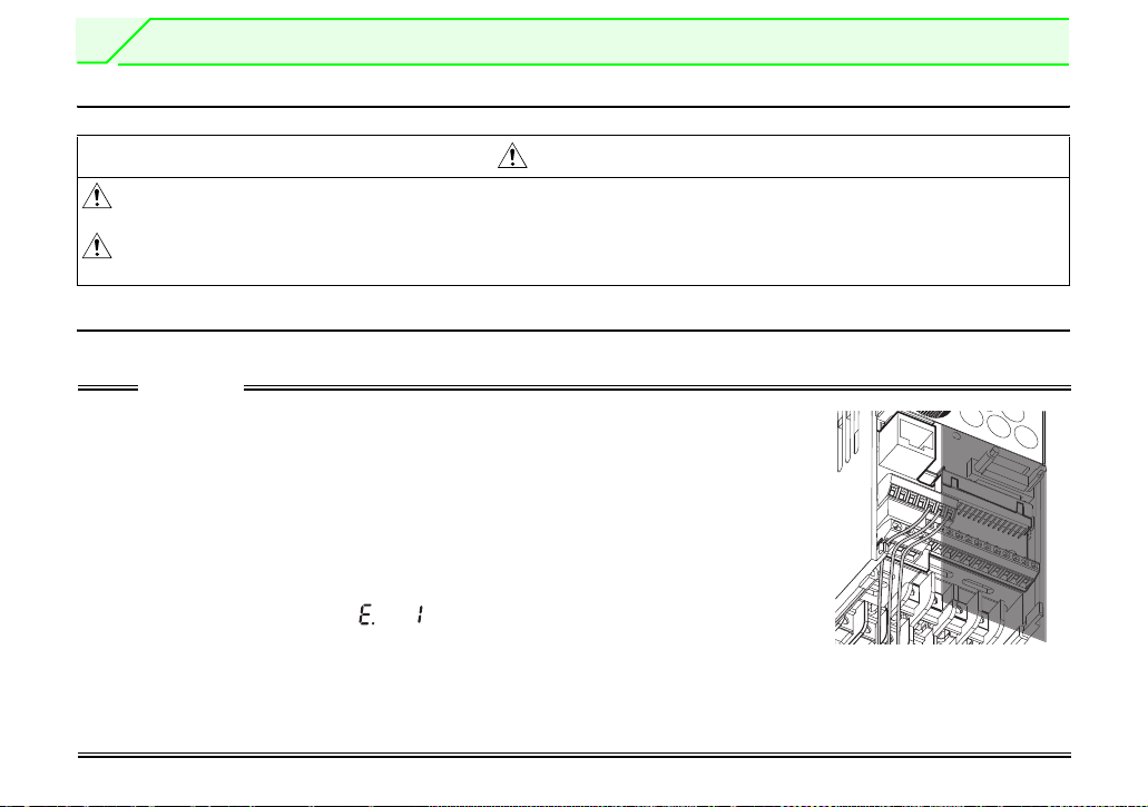
The FR-E700 series has one connection connector for the plug-in option.
CAUTION
• Always perform wiring to the main circuit terminals and control circuit terminals
before installing the option. Wiring cannot be performed after installing the
option.
For wiring to terminals RUN, FU, and SE of control circuit terminal, run cables to
prevent them from being caught between the option board and control circuit
terminal block as shown in the right figure. In case cables are caught, the
inverter may be damaged.
• When the inverter cannot recognize that the option unit is mounted due to
improper installation, etc., " " (option fault) is displayed.
• When mounting/removing an option, hold the sides of the circuit board. Do not
press on the parts on the circuit board. Stress applied to the parts by pressing, etc. may cause a failure.
• Take caution not to drop a mounting screw during mounting and removal of the option.
• Pull the option straight out when removing. Pressure applied to the connector and to the circuit board may
break the option.
Plug-in
Plug-in
option
option
6
INSTALLATION
z For FR-E720-3.7K (FR-E720-175) or lower and FR-E740-7.5K (FR-E740-170) or lower
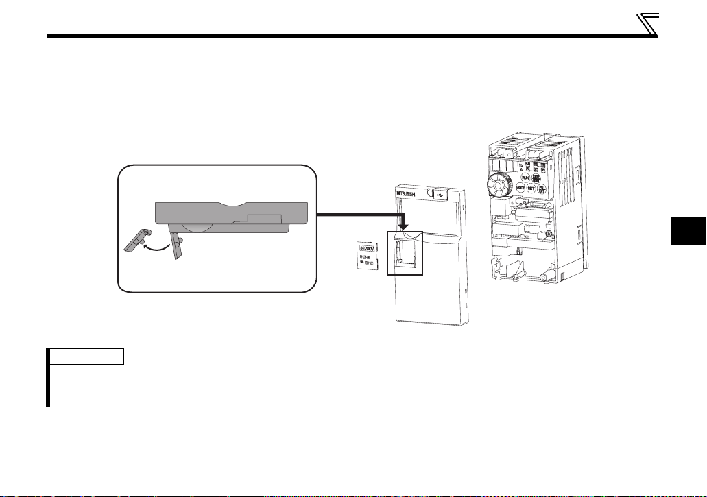
(1) Remove the front cover from the inverter. (For removing the front cover, refer to the FR-E700
instruction manual.)
(2) Remove the PU cover from the front cover. Open the PU cover with a driver, etc. and remove it in the
direction of arrow as shown below.
(1) Front cover
*
* Open the PU cover, then open it toward the arrow
direction to remove.
(2) PU cover
REMARKS
• Because the voltage class, model name and serial (only voltage class is written for FR-E740-5.5K (FR-E740-120)
or higher) are stated on the PU cover, replace a PU cover of a plug-in option front cover with the removed PU cover
from the inverter.
2
7
INSTALLATION
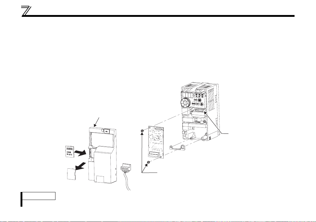
(3) Install the option protective cover.
(4) Securely fit the connector of the plug-in option to the inverter connector along the guides.
(5) Securely fix the both top and bottom of the plug-in option to the inverter with the accessory mounting
screws. (tightening torque 0.33N
•m to 0.40N•m) If the screw holes do not line-up, the connector may
not have been plugged snugly. Check for loose plugging.
(6) Remove the PU cover provided on the front cover for plug-in option and install the other PU cover,
which was removed in (2).
(7) Mount the already wired terminal block to the plug-in option. (Refer to the chapter 3 for wiring.)
(8) Install the front cover for plug-in option to the inverter.
Front cover
for plug-in option
(8)
(6) Replace
(3) Option protective cover
(7)
(5)
Mounting screws
(4)
Option
connector
of inverter
REMARKS
• When the option protective cover is not installed, the protective structure (JEM1030) changes to open type (IP00).
8
INSTALLATION
z For FR-E720-5.5K (FR-E720-240) or higher and FR-E740-11K (FR-E740-230) or higher
(1) Remove the front cover 1 and 2 from the inverter. (For removing the front cover, refer to the FR-E700
instruction manual.)
(2) Remove the PU cover from the front cover 2. For removing the PU cover, refer to page 7.
Front cover 1
1)
Front cover 2
1)
2)
PU cover
REMARKS
• Because the voltage class is stated on the PU cover, replace a PU cover of a plug-in option front cover with the
removed PU cover from the inverter.
2
9

INSTALLATION
(3) Install the front cover 1 to the inverter.
(4) Securely fit the connector of the plug-in option to the inverter connector along the guides.
(5) Securely fix the both top and bottom of the plug-in option to the inverter with the accessory mounting
screws. (tightening torque 0.33N
not have been plugged snugly. Check for loose plugging.
(6) Remove the PU cover provided on the front cover for plug-in option and install the other PU cover,
which was removed in (2).
(7) Mount the already wired terminal block to the plug-in option. (Refer to the chapter 3 for wiring.)
(8) Install the front cover for plug-in option to the inverter.
•m to 0.40N•m) If the screw holes do not line-up, the connector may
10
INSTALLATION
(6)
Replace
Front cover for
plug-in option
(8)
(7)
Front cover 1
(4) Option connector of inverter
(3)
(5) Mounting screws
2
Installation completed
11
INSTALLATION
2.3 Node Address Setting
(1) Setting with node address switch
Set the node address between "0 to 63" using node address switches on the FR-A7ND (refer to page 3).
The setting is reflected when power turns on next or the inverter is reset.
Set Pr. 345 or Class 0x03 Instance 1 Attribute 1 to "63 (initial value)".
Set the arrow (×) of the corresponding switches to the number to set a desired address.
z Setting example
0
Node address 1:
Set the "×" of X10(SW1) to "0" and the
"×" of X1(SW2) to "1".
CAUTION
• Set the inverter node address before switching on the inverter and do not change
the setting while power is on. Otherwise you may get an electric shock.
• Set the node address switch to the switch number position correctly. If the switch
is set between numbers, normal data communication can not be made.
• When the node address switch is set to values other than "0 to 63", they are regarded as "63".
• You cannot set the same node address to other devices on the network. (If different devices have the
same node address, the communication cannot be established properly.)
1
9
2
8
8
3
7
4
6
5
X10 X1
0
1
Node address 26:
9
2
3
7
4
6
5
Set the "×" of X10(SW1) to "2" and the
"×" of X1(SW2) to "6".
Good
example
0
1
9
2
8
3
7
4
6
5
0
1
9
2
8
8
3
7
7
4
6
5
X10 X1
Bad
example
0
1
9
8
7
6
5
0
1
9
2
3
4
6
5
2
3
4
12

INSTALLATION
(2) Set with parameter (Pr. 345)
Use parameter (Pr. 345) of the inverter to set. Setting node address with parameter makes the node
address setting invalid. The setting is reflected at the next power-on or inverter reset. (Refer to page 22)
(3) Setting with master
Use Class 0x03 Instance 1 Attribute 1 to set from the master. The setting change is reflected to Pr. 345.
Setting node address from the master makes the node address switch setting invalid. (Refer to page 50)
All connections are released and a set value is immediately reflected.
2
13
3 WIRING
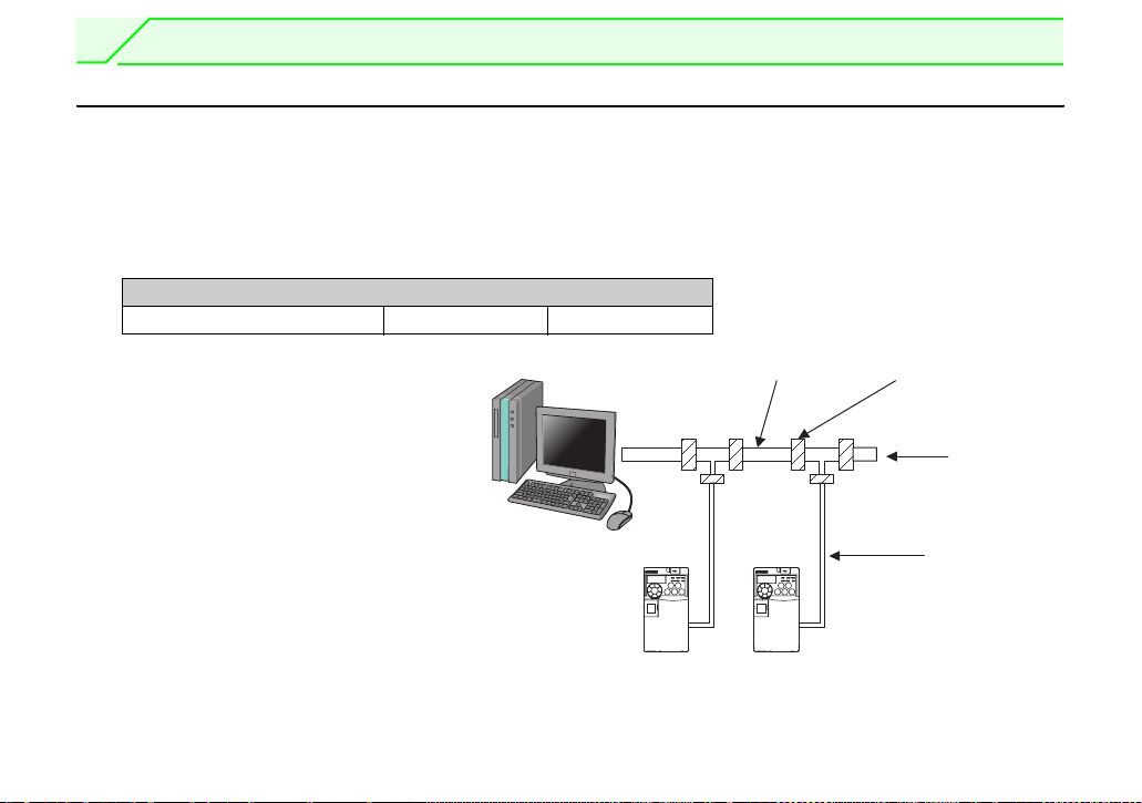
3.1 Connection to Network
(1) Be sure to check the following before connecting the inverter to the network.
· Check that the FR-A7ND is snugly inserted into the inverter. (Refer to page 6.)
· Check that the correct node address is set. (Refer to page 12.)
· Check that a drop cable is firmly connected to the FR-A7ND. (Refer to page 15.)
(2) Make sure that the terminating resistor is installed at each end (between CAN+ and CAN-) of the trunk
cable. These resistors must meet the following requirements.
Requirements of Terminating Resistors
R (resistance value) = 121Ω 1% metal film 0.25 W
(3) Connect drop cables to the trank
cable.
· If the trunk connector is a
DeviceNet sanctioned pluggable or
sealed connector, the connection
to the active network can be made
at any time whether the inverter is
on or off. The option unit
automatically detects when the
connection is completed.
· If connecting to the network with
free wires, power to the network
and inverter should be shut off as a
safety precaution in case two or more signal wires are accidentally shorted together.
Inverter Inverter
Trunk cable
Trunk connector
Terminating
resistor
Drop cable
14
WIRING
3.2 Wiring
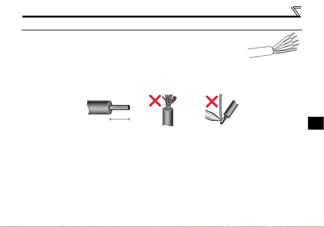
(1) Strip the insulation back about 40mm on the free wire end of the drop cable to
expose the four colored signal wires and the silver shield wire.
(2) Strip the insulation back of each signal cable to use. If the length of the sheath pealed is too long, a
short circuit may occur among neighboring wires. If the length is too short, wires might come off.
Wire the stripped cable after twisting it to prevent it from becoming loose. (Do not solder it.)
Cable stripping length
7mm
Use a blade type terminal as required.
3
15
WIRING
REMARKS
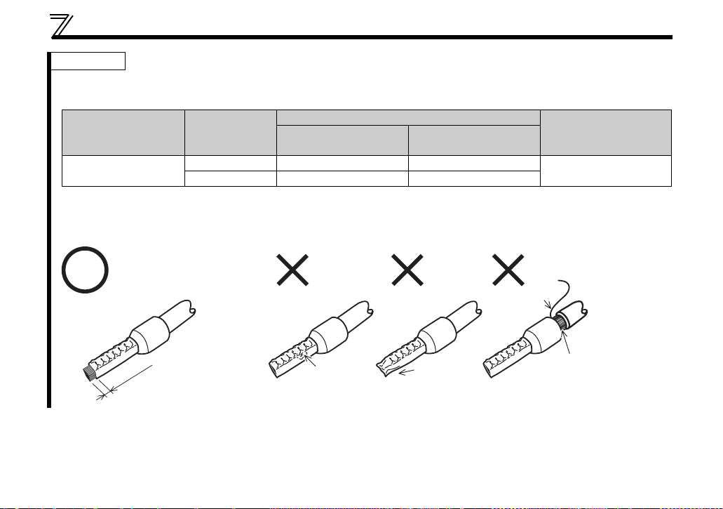
Blade terminals available on the market (as of February 2012)
zPhoenix Contact Co.,Ltd
Blade Terminal Model
sleeve
Without insulation
sleeve
Crimping Tool Name
CRIMPFOX 6
Terminal Screw Size
M3
Cable Size
2
)
(mm
With insulation
0.3 to 0.5 Al 0,5-6WH A 0,5-6
0.5 to 0.75 Al 0,75-6GY A 0,75-6
Insert wires to a blade terminal, and check that the wires come out for about 0 to 0.5 mm from a sleeve.
Check the condition of the blade terminal after crimping. Do not use a blade terminal of which the crimping is
inappropriate, or the face is damaged.
Unstranded
Wire
Shell
wires
16
Sleeve
0 to 0.5m
m
Damaged
Crumpled tip
Wires are not inserted
into the shell
WIRING
0
9
8
7
6
5
4
3
2
1
0
9
8
7
6
5
4
3
2
1
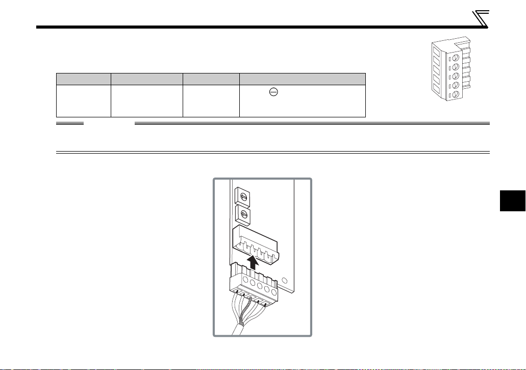
(3) Loosen the terminal screw and insert the cable into the terminal
according to the terminal arrignment.
Tighten each cable with fixing screws to the recommended tightening torque.
Screw Size
M3
Tightening Torque
0.5N•m to
0.6N•m
Cable Size Screwdriver
2
0.3mm
0.75mm
Small flat-blade screwdriver
to
(Tip thickness: 0.4mm/tip
2
width: 2.5mm)
V- (black)
CAN- (blue)
Shielded cable
CAN+ (white)
V+ (red)
Terminal layout
CAUTION
• Undertightening can cause cable disconnection or malfunction. Overtightening can cause a short
circuit or malfunction due to damage to the screw or unit.
(4) Connect the terminal block to the connector for communication of the communication option mounted
on the inverter.
3
17
WIRING
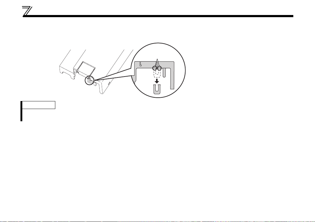
(5) When wiring the FR-E700 series, if a hook of the front cover of the plug-in option impedes wiring, cut
off the hook and perform wiring.
Cut off with a
nipper, etc.
Cut off a hook at the bottom
of the option cover.
(Cut off so that no portion is left.)
REMARKS
• When the option protective cover is not fitted or wire is not passed through even if the hook of the front cover of the
plug-in option has been cut off, the protective structure (JEM1030) changes to open type (IP00).
18
WIRING
(6) For wiring of FR-E720-5.5K (FR-E720-240) or higher and FR-E740-11K (FR-E740-230) or higher, pass
a cable on the inverter front cover as shown below. If a drop cable is passed through inside the inverter
front cover, the bending radius of the cable becomes small, stressing the cable.
CAUTION
When wiring, take care not to subject the cable to stress.
After wiring, wire offcuts must not be left in the inverter. They may cause a fault, failure or
malfunction.
3
19

4 INVERTER SETTING
4.1 Parameter List
The following parameters are used for the communication option (FR-A7ND)
Set the values according to need.
Parameter
Number
79 Operation mode selection 0 to 4, 6, 7 1 0 26
338 Communication operation command source 0, 1 1 0 30
339 Communication speed command source 0, 1, 2 1 0 30
340 Communication startup mode selection 0, 1, 10 1 0 26
342 Communication EEPROM write selection 0, 1 1 0 33
345
*1 DeviceNet address 0 to 4095 1 63 22
346
*1 DeviceNet baud rate 0 to 4095 1 132 23
349
*1 Communication reset selection 0, 1 1 0 41
500
*1 Communication error execution waiting time 0 to 999.8s 0.1s 0 34
Communication error occurrence count
*1
501
502
550
*1 Parameters which can be displayed when the plug-in option (FR-A7ND) is mounted.
*2 The setting is reflected after inverter reset or at the next power-ON.
display
*2 Stop mode selection at communication error 0, 1, 2, 3 1 0 36
NET mode operation command source
*2
selection
Name Setting Range
01035
0, 2, 9999 1 9999 29
Minimum
Setting
Increments
Initial
Value
Refer to
Page
20

INVERTER SETTING
4.2 DeviceNet Data
DeviceNet communication startup data can be set with the inverter parameter without using a DeviceNet
configuration tool.
For the setting method with a EDS file (refer to page 93) DeviceNet configuration tool, refer to the
configuration tool manual.
4
21
INVERTER SETTING
4.2.1 DeviceNet address (Pr. 345)
Parameter
Number
345 DeviceNet address 0 to 4095 1 63
Name Setting Range
Minimum Setting
Increments
Initial
Value
The definition of Pr. 345 is as follows.
Bit15 Bit14 Bit13 Bit12 Bit11 Bit10 Bit9 Bit8 Bit7 Bit6 Bit5 Bit4 Bit3 Bit2 Bit1 Bit0
Address Key (AKey) Not Available Device Node Address (Addr)
Communication continuation selection(ResCom)
Bit Item
0 to 5
12 to 15 Address Key (AKey) 0 0
Device Node
Address (Addr)
Selection of
continuous
11
communication at
inverter reset
(ResCom)
Initial
Value
Setting
Range
63 0 to 63
0
0
1
Definition
Node Address (MAC ID) of device
is set between 0 to 63.
Set "63" (initial value) to set node
address with node address switch.
Reset the option unit in synchronization with the inverter.
When connection is timed out, communication may not resume
according to the master action. In this case, release connection and
reestablish to make communication enabled.
The option unit will not be reset even if the inverter is reset and
communication continues.
After inverter reset, preset a value other than "0" in Pr. 340 so that
the inverter starts in network operation mode.
Set "0" always. When a value other than "0" is set, the inverter
operates as when "63" (initial value) is set in Pr. 345.
Node address can be set with
DeviceNet Object Class 0x03,
Instance1, Attribute1. (Refer to
page 50)
22
4.2.2 DeviceNet baud rate (Pr. 346)
INVERTER SETTING
Parameter
Number
346 DeviceNet baud rate 0 to 4095 1 132
Name Setting Range
Minimum Setting
Increments
Initial
Val ue
Set baud rate etc. to start DeviceNet communication.
Bit15 Bit14 Bit13 Bit12 Bit11 Bit10 Bit9 Bit8 Bit7 Bit6 Bit5 Bit4 Bit3 Bit2 Bit1 Bit0
Baud Rate Key Input Assembly (IA) Output Assembly (OA)
Bit Item
0, 1 Baud Rate (BR) 0
Output
2 to 6
Assembly (OA)
7 to 11
12 to 15 Baud Rate Key 0 0
Input Assembly
(IA)
Initial
Value
Setting Range Definition
0, 3 125kbps
1 250kbps
2 500kbps
0
1
Other than the above Output Instance 21 (0x15)
1
Other than the above Input Instance 71 (0x47)
1
6
0
1
6
Output Instance 20 (0x14)
Output Instance 21 (0x15)
Output Instance 126 (0x7E)
Input Instance 70 (0x46)
Input Instance 71 (0x47)
Input Instance 176 (0xB0)
Set "0" always. When a value other than "0" is set, the inverter
operates as when "132" (initial value) is set in Pr. 346.
This value can be set with DeviceNet
Object Class 0x03 Instance 1
Attribute 2.
· Set the same value for input
assembly and output assembly.
· The value can be set with Control
Supervisor Class 0x29 Instance 1
Attribute 140, 141. (Refer to page
69)
(Refer to page 50)
Baud Rate
(BR)
4
23
 Loading...