

Mitsubishi Electric FR-A7NC E kit-SC Instruction Manual

INVERTER
PRE-OPERATION INSTRUCTIONS
1
FR-A7NC E kit-SC
INSTRUCTION MANUAL
communication function
HOW TO CHECK FOR ERROR USING THE LEDS
INSTALLATION
2
WIRING
3
INVERTER SETTING
4
FUNCTION OVERVIEW
5
I/O SIGNAL LIST
6
DETAILS OF INPUT AND OUTPUT SIGNALS
7
PROGRAMMING EXAMPLES
8
9
Thank you for choosing this Mitsubishi Inverter plug-in option.
WARNING
CAUTION
CAUTION
This Instruction Manual gives handling information and
precautions for use of this equipment. Incorrect handling might
cause an unexpected fault. Before using the equipment, please
read this manual carefully to use the equipment to its optimum.
Please forward this manual to the end user.
This section is specifically about
safety matters
Do not attempt to install, operate, maintain or inspect this
product until you have read through this Instruction Manual and
appended documents carefully and can use the equipment
correctly. Do not use this product until you have a full
knowledge of the equipment, safety information and
instructions.
In this Instruction Manual, the safety instruction levels are
classified into "WARNING" and "CAUTION".
Incorrect handling may cause
hazardous conditions, resulting in
death or severe injury.
Incorrect handling may cause
hazardous conditions, resulting in
medium or slight injury, or may cause
only material damage.
The level may even lead to a serious
consequence according to conditions. Both instruction levels
must be followed because these are important to personal
safety.
SAFETY INSTRUCTIONS
1. Electric Shock Prevention
WARNING
While power is ON or when the inverter is running, do not
open the front cover. You may get an electric shock.
Do not run the inverter with the front cover or wiring cover
removed. Otherwise, you may access the exposed highvoltage terminals and charging part and get an electric shock.
Even if power is OFF, do not remove the front cover except for
wiring or periodic inspection. You may accidentally touch the
charged inverter circuits and get an electric shock.
Before wiring or inspection, power must be switched OFF. To
confirm that, LED indication of the operation panel must be
checked. (It must be OFF.) Any person who is involved in
wiring or inspection shall wait for at least 10 minutes after the
power supply has been switched OFF and check that there
are no residual voltage using a tester or the like. The
capacitor is charged with high voltage for some time after
power OFF, and it is dangerous.
Any person who is involved in wiring or inspection of this
equipment shall be fully competent to do the work.
The plug-in option must be installed before wiring. Otherwise,
you may get an electric shock or be injured.
Do not touch the plug-in option or handle the cables with wet
hands. Otherwise you may get an electric shock.
Do not subject the cables to scratches, excessive stress,
heavy loads or pinching. Otherwise you may get an electric
shock.
A-1
2. Injury Prevention
3) Usage
CAUTION
The voltage applied to each terminal must be the ones
specified in the Instruction Manual. Otherwise burst, damage,
etc. may occur.
The cables must be connected to the correct terminals.
Otherwise burst, damage, etc. may occur.
Polarity must be correct. Otherwise burst, damage, etc. may
occur.
While power is ON or for some time after power-OFF, do not
touch the inverter as they will be extremely hot. Doing so can
cause burns.
3. Additional Instructions
Also the following points must be noted to prevent an accidental
failure, injury, electric shock, etc.
1) Transportation and mounting
CAUTION
Do not install or operate the plug-in option if it is damaged or
has parts missing.
Do not stand or rest heavy objects on the product.
The mounting orientation must be correct.
Foreign conductive objects must be prevented from entering
the inverter. That includes screws and metal fragments or
other flammable substances such as oil.
2) Trial run
CAUTION
Before starting operation, each parameter must be confirmed
and adjusted. A failure to do so may cause some machines to
make unexpected motions.
WARNING
Do not modify the equipment.
Do not perform parts removal which is not instructed in this
manual. Doing so may lead to fault or damage of the inverter.
CAUTION
When parameter clear or all parameter clear is performed, the
required parameters must be set again before starting operations
because all parameters return to the initial value.
For prevention of damage due to static electricity, nearby
metal must be touched before touching this product to
eliminate static electricity from your body.
4) Maintenance, inspection and parts replacement
CAUTION
Do not test the equipment with a megger (measure insulation
resistance).
5) Disposal
CAUTION
This inverter plug-in option must be treated as industrial
waste.
6) General instruction
Many of the diagrams and drawings in this Instruction Manual
show the inverter without a cover or partially open for
explanation. Never operate the inverter in this manner. The
cover must be reinstalled and the instructions in the inverter
manual must be followed when operating the inverter.
A-2

— CONTENTS —
1 PRE-OPERATION INSTRUCTIONS 1
1.1 Unpacking and product confirmation ..............................................................................................1
1.1.1 Product confirmation....................................................................................................................................... 1
1.2 Parts ....................................................................................................................................................2
1.3 Inverter option specifications...........................................................................................................4
1.4 CC-Link version .................................................................................................................................5
1.4.1 CC-Link ver. 1.10............................................................................................................................................ 5
1.4.2 CC-Link ver. 2................................................................................................................................................. 5
2 INSTALLATION 6
2.1 Pre-installation instructions .............................................................................................................6
2.2 Installation procedure .......................................................................................................................6
3WIRING 12
3.1 System configuration example.......................................................................................................12
3.2 Connection of several inverters .....................................................................................................13
3.3 Connection cable .............................................................................................................................16
3.4 Wiring ................................................................................................................................................16
4 INVERTER SETTING 19
I

4.1 Parameter list ...................................................................................................................................19
4.2 Operation Mode Setting ..................................................................................................................20
4.2.1 Operation mode indicator.............................................................................................................................20
4.2.2 Operation mode switching and communication startup mode (Pr. 79, Pr. 340) ...........................................21
4.3 Start and Speed Command Sources (Pr. 338, Pr. 339, Pr. 550) ...................................................24
4.3.1 Communication EEPROM write selection (Pr. 342) ..................................................................................... 28
4.4 Operation at Communication Error Occurrence ...........................................................................29
4.4.1 Operation selection at communication error occurrence (Pr. 500 to Pr. 502) ..............................................29
4.4.2 Fault and measures...................................................................................................................................... 33
4.5 Inverter Reset ...................................................................................................................................34
4.6 CC-Link function setting .................................................................................................................36
4.6.1 Station number setting (Pr. 542)...................................................................................................................36
4.6.2 Baud rate setting (Pr. 543) ...........................................................................................................................37
4.6.3 Frequency command with sign (Pr. 541)......................................................................................................38
5 FUNCTION OVERVIEW 39
5.1 Function block diagram ..................................................................................................................39
5.2 Output from the inverter to the network ........................................................................................40
5.3 Input to the inverter from the network ...........................................................................................41
6 I/O SIGNAL LIST 42
6.1 CC-Link extended setting (Pr. 544) ................................................................................................42
6.2 I/O signal list.....................................................................................................................................43
II

6.2.1 I/O signal when CC-Link ver.1 one station (FR-E500 series compatible) is occupied (Pr. 544 = 0) ............43
6.2.2 I/O signal when CC-Link ver.1 one station is occupied (Pr. 544 = "1") ........................................................46
6.2.3 I/O signal when CC-Link ver.2 double setting is selected (Pr. 544 = "12")...................................................47
6.2.4 I/O signal when CC-Link ver.2 quadruple setting is selected (Pr. 544 = "14") ............................................. 48
6.2.5 I/O signal when CC-Link ver.2 octuple setting is selected (Pr. 544 = "18") ..................................................49
7 DETAILS OF INPUT AND OUTPUT SIGNALS 51
7.1 Details of remote input and output signals ...................................................................................51
7.1.1 Output signals (master module to inverter (FR-A7NC)) ...............................................................................51
7.1.2 Input signals (inverter (FR-A7NC) to master module) ..................................................................................53
7.2 Details of remote register................................................................................................................55
7.2.1 Remote register (master module to inverter (FR-A7NC)).............................................................................55
7.2.2 Remote register (inverter (FR-A7NC) to master module) .............................................................................58
7.2.3 Instruction codes ..........................................................................................................................................61
7.2.4 Monitor codes ...............................................................................................................................................66
8 PROGRAMMING EXAMPLES 68
8.1 Program example for reading the inverter status.........................................................................71
8.2 Program example for setting the operation mode........................................................................72
8.3 Program example for setting the operation commands ..............................................................73
8.4 Program example for monitoring the output frequency ..............................................................74
8.5 Program example for parameter reading.......................................................................................75
8.6 Program example for parameter writing ........................................................................................76
8.7 Program example for setting the running frequency ...................................................................77
III

8.8 Program example for fault record reading ....................................................................................79
8.9 Program example for resetting the inverter at inverter error ......................................................80
8.10 Instructions ......................................................................................................................................81
9 HOW TO CHECK FOR ERROR USING THE LEDS 83
9.1 When one inverter is connected.....................................................................................................83
9.2 When two or more inverters are connected ..................................................................................85
9.3 Communication stops during operation........................................................................................87
IV
1 PRE-OPERATION INSTRUCTIONS
1.1 Unpacking and product confirmation
Take the plug-in option out of the package, check the product name, and confirm that the product is as you
ordered and intact.
This product is a plug-in option dedicated for the FR-E700-SC series
1.1.1 Product confirmation
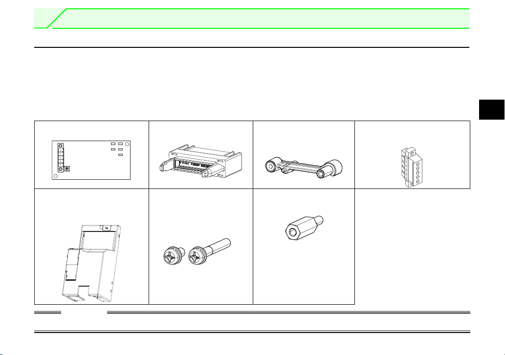
Check the enclosed items.
Plug-in option ................... 1 Junction connector...........1
SD
L.RUN
RD
L.ERR
ON
12
SW2
RUN
(Refer to page 7, 9.)
Spacer for plug-in option
mounting....................1
(Refer to page 7, 9.)
(Safety stop function model).
Terminal block................... 1
(Refer to page 16)
1
Front cover for plug-in option
......................................... 1
(Refer to page 7, 9.)
M3 mounting screw
(Long) (M3 20mm).......1
(Short) (M3 6mm)........1
Hexagon spacer..............1
(Refer to page 7, 9.)
(Refer to page 7, 9.)
CAUTION
Install a provided front cover for plug-in option, in place of the inverter front cover .
1
PRE-OPERATION INSTRUCTIONS
(Refer to page 13.)
(Refer to page 3.)
(Refer to page 16.)
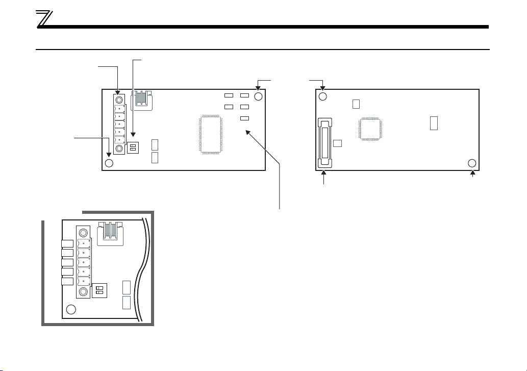
1.2 Parts
Connector for
communication
Mount the
accessory
terminal block to
connect to the
network.
Mounting
hole
Terminal
layout
DA
DB
DG
SLD
FG
Terminating resistor selection switch
Select the resistor value of the terminating resistor.
Front view Rear view
SD
L.RUN
RD
L.ERR
RUN
ON
12
SW2
Mounting
hole
Mounting hole
Connector
Connect to the inverter option connector.
Operation status indication LED
Lit/flicker of the LED indicate operation status.
ON
12
SW2
2
PRE-OPERATION INSTRUCTIONS
Operation status indication LED
LED Description
L.RUN
L.ERR
RUN
SD Turns OFF when no data is transmitted.
RD Lit when the received data carrier is detected.
REMARKS
Set transmission baud rate using Pr.543 Baud rate selection (CC-Link). (Refer to page 37.)
Lit when refresh data is properly received. Turns OFF when a data transmission is stopped for a
certain period of time.
Lit when a communication error occurs in the own station and flickers when settings of switch, etc.
are changed while power is ON.
Flickers when the Pr. 542 or Pr. 543 setting is changed.
Turn the power ON again or turn the RES signal ON. (Refer to page 36, 37.)
Lit during normal operation (5V is supplied in the board) (Lit even in the noncommunication status.)
Flickers when the master station is CC-Link ver.1 and the FR-A7NC is CC-Link ver.2 compatible.
(Refer to page 5.)
Set the station number using Pr. 542 Communication station number (CC-Link). (Refer to page 36.)
1
3

PRE-OPERATION INSTRUCTIONS
1.3 Inverter option specifications
Typ e Inverter plug-in option type, terminal block connectable
Power supply 5VDC supplied from the inverter
Number of units
connected
Cable size
Station type Remote device station
Number of stations
occupied
Communication cable CC-Link dedicated cable, CC-Link ver. 1.10 compatible CC-Link dedicated cable
42 units max. (Refer to page 42 for the number of stations occupied.) May be used with other
equipment.
2
to 0.75mm
0.3mm
CC-Link ver.1: occupies one station
CC-Link ver.2: occupies one station (selectable from among double, quadruple and octuple)
2
4
1.4 CC-Link version
Master station
(CC-Link ver.1)
Master station
(CC-Link ver.2)
CC-Link ver.1
setting
CC-Link ver.1
setting
CC-Link ver.2
setting
CC-Link ver.2
setting
Communication
enabled
Communication
enabled
Communication
disabled
("RUN" LED flickers)
1.4.1 CC-Link ver. 1.10
The conventional CC-Link products, whose inter-station cable lengths have equally been changed to 20cm
(7.87 inch) or more to improve the inter-station cable length restriction, are defined as CC-Link ver. 1.10. In
comparison, the conventional products are defined as CC-Link ver. 1.00.
Refer to the CC-Link Master Module Manual for the maximum overall cable lengths and inter-station cable
lengths of CC-Link ver. 1.00 and ver. 1.10.
CC-Link ver. 1.10 compatibility conditions
1)All modules that comprise a CC-Link system should be compatible with CC-Link ver. 1.10.
2)All data link cables should be CC-Link ver. 1.10 compatible, CC-Link dedicated cables.
(CC-Link ver. 1.10 compatible cables have a logo or ver. 1.10 indication.)
In a system that uses the CC-Link ver. 1.00 and ver. 1.10 modules and cables together, the maximum overall
cable length and inter-station cable length are as specified for CC-Link ver. 1.00.
1.4.2 CC-Link ver. 2
The FR-A7NC is compatible with CCLink ver.2.
When using the CC-Link ver.2 setting
with the FR-A7NC, the master station
needs to be compatible with the CCLink ver.2.
For CC-Link ver.2, double, quadruple
and octuple settings can be used to
increase the remote register (RWr/w)
points.
CAUTION
PRE-OPERATION INSTRUCTIONS
1
5
2 INSTALLATION
2.1 Pre-installation instructions
Make sure that the input power of the inverter is OFF.
CAUTION
With input power ON, do not install or remove the plug-in option. Otherwise, the inverter and
plug-in option may be damaged.
For prevention of damage due to static electricity, touch nearby metal before touching this
product to eliminate static electricity from your body.
2.2 Installation procedure
CAUTION
Always perform wiring to the main circuit terminals and control circuit terminals before installing the
option. Wiring cannot be performed after installing the option.
When mounting the plug-in option, do not let wires get caught in the plug-in option or the spacer for option
mounting. If a wire gets caught, the inverter and the plug-in option may be damaged.
When the inverter cannot recognize that the option unit is mounted due to improper installation, etc.,
" " (option fault) is displayed.
When mounting/removing an option, hold the sides of the circuit board. Do not press on the parts on the
circuit board. Stress applied to the parts by pressing, etc. may cause a failure.
Take caution not to drop mounting screws during the mounting and removal of the option.
Pull the option straight out when removing. Pressure applied to the connector and to the circuit board may
break the option.
REMARKS
Because the voltage class, model name and serial number (only voltage class is labeled for FR-E720-5.5KSC (FR-
E720-240SC), FR-E740-5.5KSC (FR-E740-120SC) or higher) are written on the PU cover, replace the PU cover of
the plug-in option with the removed PU cover of the inverter.
6
INSTALLATION
2
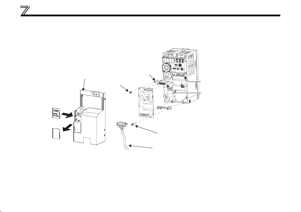
(1) Front cover
(2) PU cover
* Open the PU cover, then open it toward the arrow
direction to remove.
Inverter with one front cover
(1) Remove the front cover from the inverter. (For removing the front cover, refer to the FR-E700
instruction manual.)
(2) Remove the PU cover from the front cover. Open the PU cover with a driver, etc. and remove it in the
direction of arrow as shown below.
(3) Mount the spacer for plug-in option mounting, the hexagon spacer, and the junction connector. Fit the
junction connector to the guide of the connector at the inverter side, and insert the junction connector
as far as it goes.
(4) Fit the connector of the plug-in option to the guide of the junction connector, and insert the plug-in
option as far as it goes.
(5) Fix the plug-in option securely by using the supplied mounting screw (short) to the upper screw hole
and the other supplied mounting screw (long) to the lower screw hole of the plug-in option. If the screw
holes do not line up, the connector may not have been plugged properly. Check for loose plugging.
Tightening torque: 0.33 to 0.4Nm
7
INSTALLATION
(7)
(3) Hexagon
spacer
(3) Junction connector
(5) Mounting screws
(short)
(5) Mounting screw (long)
(7) CC-Link communication cable
(8)
(4)
(3) Plug-in option connector
of inverter
(3) Spacer for plug-in option mounting
(6) Replace
Front cover
for plug-in option
(6) Remove the PU cover provided on the front cover for plug-in option and install the other PU cover,
which was removed in (2).
(7) Mount the already wired terminal block to the plug-in option. (Refer to Chapter 3 for wiring.)
(8) Install the front cover for plug-in option to the inverter.
8
INSTALLATION
2
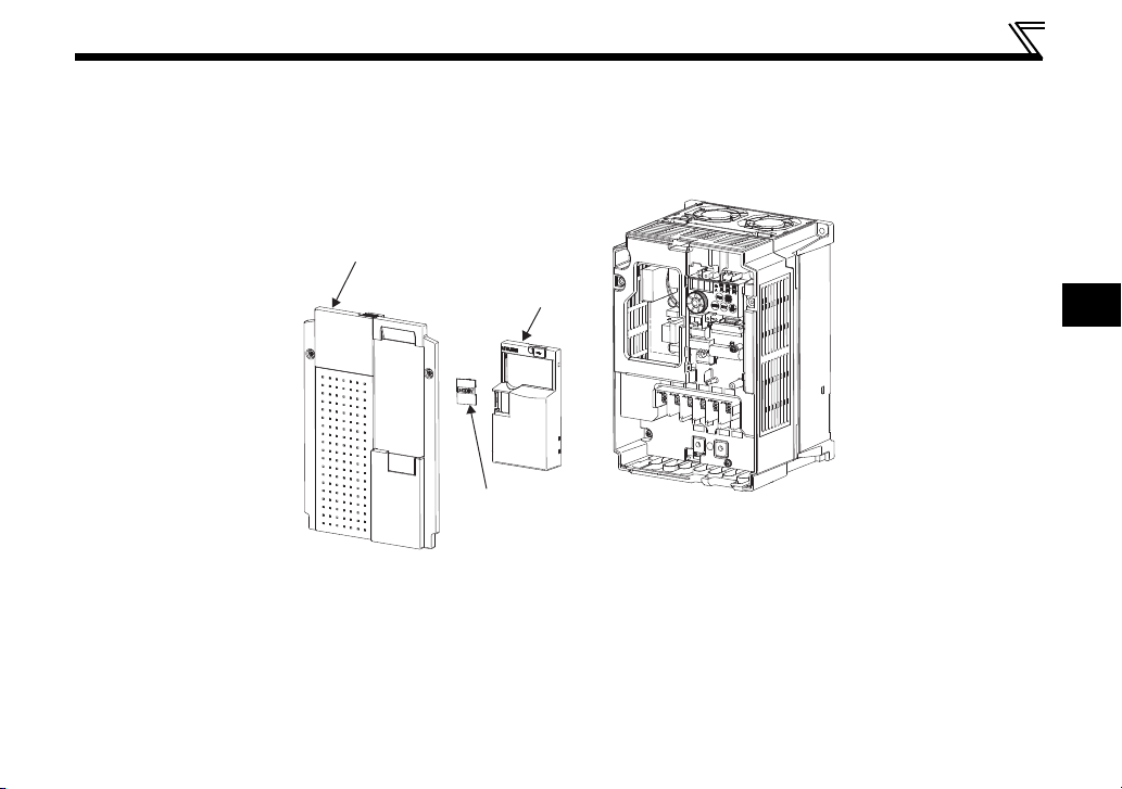
Front cover 1
Front cover 2
(1)
(2)
PU cover
(1)
Inverter with front covers 1 and 2
(1) Remove the front covers 1 and 2 from the inverter. (For removing the front cover, refer to the FR-E700
instruction manual.)
(2) Remove the PU cover from the front cover 2. For removing the PU cover, refer to page 7.
9

INSTALLATION
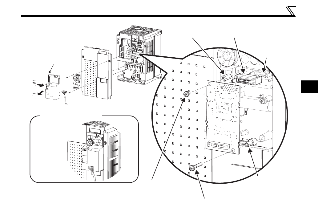
(3) Install the front cover 1 to the inverter.
(4) Mount the spacer for plug-in option mounting, the hexagon spacer, and the junction connector. Fit the
junction connector to the guide of the connector at the inverter side, and insert the junction connector
as far as it goes.
(5) Fit the connector of the plug-in option to the guide of the junction connector, and insert the plug-in
option as far as it goes.
(6) Fix the plug-in option securely by using the supplied mounting screw (short) to the upper screw hole
and the other supplied mounting screw (long) to the lower screw hole of the plug-in option. If the screw
holes do not line up, the connector may not have been plugged properly. Check for loose plugging.
Tightening torque: 0.33 to 0.4Nm
(7) Remove the PU cover provided on the front cover for plug in option and install the other PU cover,
which was removed in (2).
(8) Mount the already wired terminal block to the plug-in option. (Refer to Chapter 3 for wiring.)
Pass the CC-Link cable over the front cover 1 of the inverter. (Refer to the finished installation figure in
the next page.) If a CC-Link cable is passed through underneath the front cover 1, the bending radius
of the cable shortens, stressing the cable.
(9) Install the front cover for plug-in option to the inverter.
10
INSTALLATION
2
(9)
(3)
(5)
Installation completed
(7)
Replace
Front cover for
plug-in option
(4) Plug-in option
connector
of inverter
(8) CC-Link communication cable
(4) Hexagon
spacer
(4) Junction
connector
(6) Mounting screws
(short)
(4) Spacer for
plug-in option
mounting
(6) Mounting screw (long)
11
3 WIRING
3.1 System configuration example
(1) Programmable controller side
Mount the "QJ61BT11N", "AJ61QBT11", "A1SJ61QBT11", "AJ61BT11", "A1SJ61BT11" or "LJ61BT11" "CC-
Link system master/local module" on the main or extension base unit having the programmable controller
CPU used as the master station.
(2) Inverter side
Mount the option (FR-A7NC) on the inverter.
(3) Connect the programmable controller CC-Link module master station and the terminal block supplied with the
FR-A7NC with the CC-Link dedicated cable. After connecting the terminal block to the FR-A7NC, fit the front
cover.
Manual of the CC-Link master station
QJ61BT11N type
CC-Link System Master/Local Module
User's Manual ...SH-080394E
AJ61QBT11/A1SJ61QBT11 type
Control & Communication Link System
Master/Local Module User's Manual ...IB-66722
AJ61BT11/A1SJ61BT11 type
Control & Communication Link System
Master/Local Module User's Manual ...IB-66721
LJ61BT11 type
CC-Link System Master/Local Module User's
Manual ...SH-080895ENG
Master station
Terminating resistor
CC-Link dedicated cable
QJ61BT11N,
etc.
Power
supply
Inverter
Up to 42
units can be
connected
when only
inverters are
connected
Motor
Remote device station
REMARKS
• When the CPU has automatic refresh function (example: QnA series CPU)
When the END instruction is executed by the programmable controller CPU, the buffer memory is automatically refreshed to
enable communication with a remote device.
• When the CPU does not have automatic refresh function (example: AnA series CPU)
Sequence ladder logic is configured to perform direct communication with the buffer memory of the master station and to
enable communication with a remote device.
Power
supply
Inverter
Terminating
resistor
Motor
12
3
3.2 Connection of several inverters
Shielded
twisted cable
DA
DB
DG
SLD
FG
Terminating
resistor
*1
Terminating
resistor
selection
switch (SW2)
*3
Master module
Blue
White
Yellow
FR-A7NC*2
FR-A7NC
Shielded
twisted cable
DA
DB
DG
SLD
FG
DA
DB
DG
SLD
FG
Blue
White
Yellow
130 is a resistance value for the CC-Link
ver.1.00 dedicated high performance
cable.
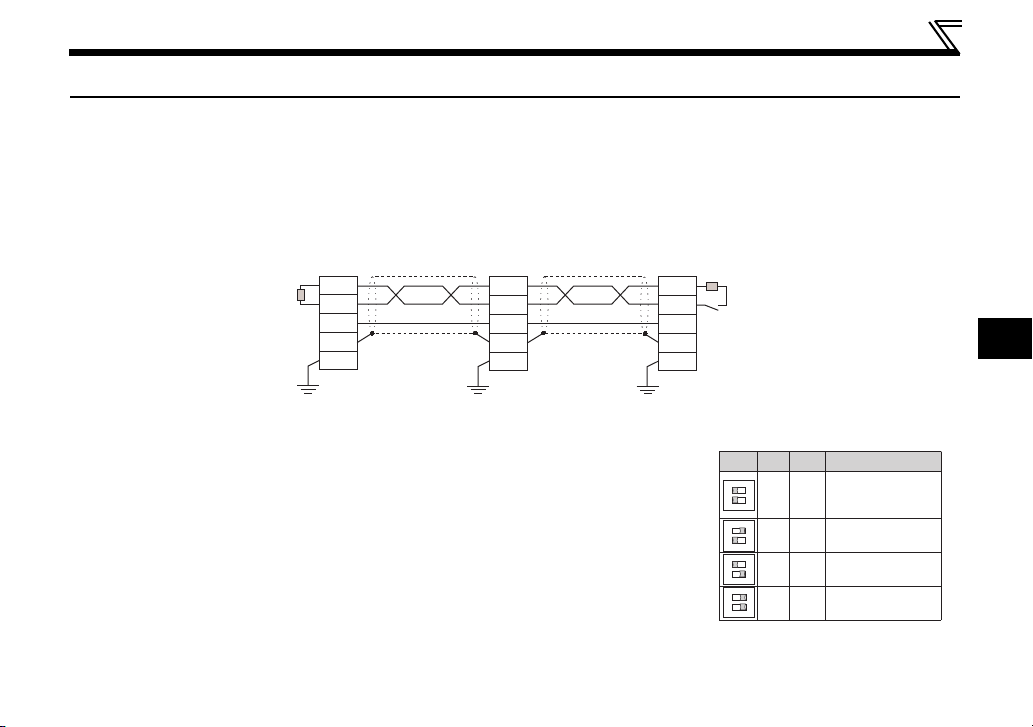
An inverter can join the link system as a CC-Link remote device station, and such device stations can be
controlled and monitored with a user program of a programmable controller. These devices can be useful
components of an automated factory.
For the shield cable of the CC-Link dedicated cable, connect it to "SLD" of each unit and always earth
(ground) it via "FG".
Terminals SLD and FG are connected inside the unit.
*1 Use the terminating resistors supplied with the programmable controller.
*2 For the unit in the middle, set 1 and 2 of SW2 to OFF (without terminating resistor).
*3 Perform setting of the terminating resistor selection switch (SW2).
(Refer to page 2 for the position of the switch.)
When connecting a terminating resistor separately, do not use a built-in
terminating resistor. (SW2 1-OFF, 2-OFF)
12
12
12
12
12
ON
OFFOFF
ON
ON OFF
ON
OFF ON
ON
ON ON
WIRING
Description
Without
terminating
resistor
Do not use.
130Ω
110 Ω
13
Cut
Cut the tube
Tube
If any other units are included, the number of stations occupied depends on the unit
and therefore the following conditions must be satisfied:
{(1 a) + (2 b) + (3 c) + (4 d)} 64
a: Number of units occupying 1 station c: Number of units occupying 3 stations
b: Number of units occupying 2 stations d: Number of units occupying 4 stations
{(16 A) + (54 B) + (88 C)} 2304
A: Number of remote I/O 64
B: Number of remote device stations 42
C: Number of local, standby master and intelligent device stations 26
WIRING
REMARKS
When performing online exchange
The built-in terminating resistor cannot be exchanged online since the terminating resistor is on the FR-A7NC board
and disconnected when the terminal block is removed from the FR-A7NC connector for communication. When
changing the FR-A7NC online, connect a terminating resistor supplied with a programmable controller master module
to the FR-A7NC after modifying it and do not use the internal terminating resistor (SW2 1-OFF, 2-OFF).
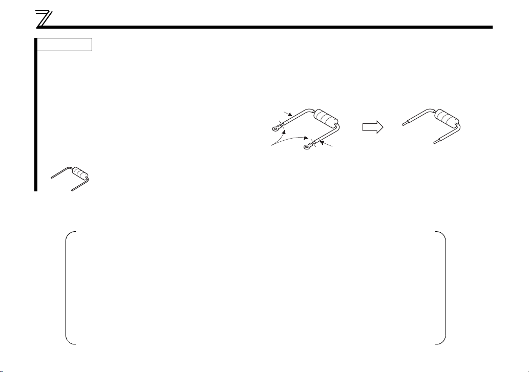
Connection with the terminating resistor
Connect the terminating resistor between terminals
DA-DB of the FR-A7NC at the end.
Modify the terminating resistors supplied with the
programmable controller to use.
When a resistor is not supplied with the master
module, use a resistor with 110 1/2W available on the market.
(1) Maximum number of units connected to one master station (CC-Link ver.1.10)
42 units (when connections are inverters only)
14

3
(2) Maximum number of units connected to one master station (CC-Link ver.2.00)
If any other units are included, the number of stations occupied depends on the unit and
therefore the following conditions must be satisfied:
• {(a + a2 + a4 + a8) + (b + b2 + b4 + b8) 2 + (c + c2 + c4 + c8) 3 + (d + d2 + d4 + d8) 4} 64
•{(a 32 + a2 32 + a4 64 + a8 128) + (b 64 + b2 96 + b4 192 + b8 384) + (c
96 + c2 160 + c4 320 + c8 640) + (d 128 + d2 224 + d4 448 + d8 896)} 8192
•{(a 4 + a2 8 + a4 16 + a8 32) + (b 8 + b2 16 + b4 32 + b8 64) + (c 12 +
c2 24 + c4 48 + c8 96) + (d 16 + d2 32 + d4 64 + d8 128)} 2048
a: Number of single setting devices occupying one station
b: Number of single setting devices occupying two stations
c: Number of single setting devices occupying three stations
d: Number of single setting devices occupying four stations
a2: Number of double setting devices occupying one station
b2: Number of double setting devices occupying two stations
c2: Number of double setting devices occupying three stations
d2: Number of double setting devices occupying four stations
a4: Number of quadruple setting devices occupying one station
b4: Number of quadruple setting devices occupying two stations
c4: Number of quadruple setting devices occupying three stations
d4: Number of quadruple setting devices occupying four stations
a8: Number of octuple setting devices occupying one station
b8: Number of octuple setting devices occupying two stations
c8: Number of octuple setting devices occupying three stations
d8: Number of octuple setting devices occupying four stations
• 16 A + 54 B + 88 C 2304
A: Numbers of remote I/O 64
B: Number of remote device stations 42
C: Number of local and intelligent device stations 26
42 units (when connections are inverter only)
WIRING
15
WIRING
6.5mm
3.3 Connection cable
In the CC-Link system, use CC-Link dedicated cables.
If the cable used is other than the CC-Link dedicated cable, the performance of the CC-Link system is not
guaranteed.
For the specifications of the CC-Link dedicated cable, refer to the website of the CC-Link Partner
Association.
Website of the CC-Link Partner Association http://www.cc-link.org/
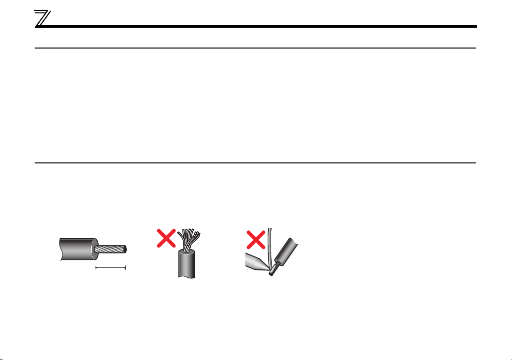
3.4 Wiring
(1) Strip off the sheath of the CC-Link dedicated cable and twist wires to use. If the length of the sheath
pealed is too long, a short circuit may occur among neighboring wires. If the length is too short, wires
might come off.
Use recommended cables. (Refer to page 16.) Recommended tightening torque : 0.22Nm to 0.25Nm
Wire the stripped cable after twisting it to prevent it from becoming loose. (Do not solder it.)
Cable stripping length
Use a blade type terminal as required.
16
WIRING
3
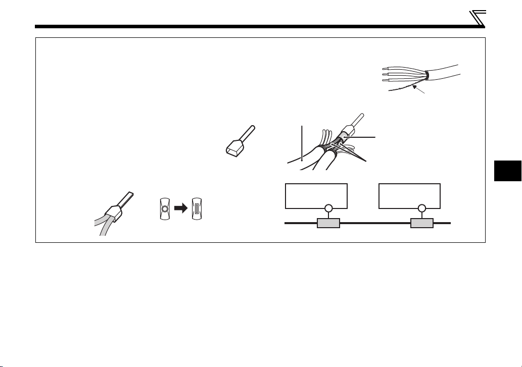
Recommended blade terminal
For wiring of the CC-link communication signal, two CCLink dedicated cables need to be twisted to wire to one
terminal block.
It is recommended to use the following blade terminal and
tool.
Recommended products (as of February 2012):
Phoenix Contact Co.,Ltd.
Blade terminal model: AI-TWIN2
Blade terminal crimping tool: CRIMPFOX 6
Note the crimping method.
Hold the long side in a longitudinal direction and insert it
into the terminal block.
0,5-8WH
Connection of the shielding wires of the
CC-Link dedicated cable
Twist the shielding wires and
wire to the terminal SLD.
Use a compression tube and
junction terminal block.
Use of a compression tube
CC-Link dedicated
cable
Prevent looseness with
a compression tube
Shielding wires
Use of a junction terminal block
FR-A7NC
SLD
Junction terminal block Junction terminal block
FR-A7NC
Shielding wires
SLD
17
WIRING
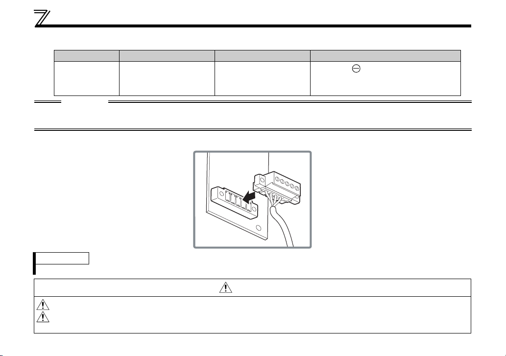
(2) Loosen the terminal screw and insert the cable into the terminal.
Screw Size Tightening Torque Cable Size Screwdriver
M2
0.22N
m to 0.25Nm
0.3mm
2
to 0.75mm
2
Small flat-blade screwdriver
(Tip thickness: 0.4mm /tip width:
2.5mm)
CAUTION
Undertightening can cause cable disconnection or malfunction. Overtightening can cause a short circuit or
malfunction due to damage to the screw or unit.
(3) Connect the terminal block to the connector for communication of the communication option.
REMARKS
• If the terminal block of the FR-A7NC is removed, the built-in terminating resistor cannot be used. (Refer to page 13.)
CAUTION
When wiring, take care not to subject the cable to stress.
After wiring, wire offcuts must not be left in the inverter. They may cause a fault, failure or
malfunction.
18

4
4 INVERTER SETTING
4.1 Parameter list
The following parameters are used for the plug-in option (FR-A7NC).
Set the values according to need.
Parameter
Number
Name Setting Range
79 Operation mode selection 0 to 4, 6, 7 1 0 21
313
*1 DO0 output selection
*1 DO1 output selection
314
0, 1, 3, 4, 7, 8, 11 to 16, 20, 25,
26, 46, 47, 64, 80, 81, 90, 91,
93, 95, 96, 98, 99, 100, 101,
103, 104, 107, 108, 111 to 116,
120, 125, 126, 146, 147, 164,
315
*1 DO2 output selection
180, 181, 190, 191, 193, 195,
196, 198, 199, 9999
338 Communication operation command source 0, 1 1 0 24
339 Communication speed command source 0, 1, 2 1 0 24
340 Communication startup mode selection 0, 1, 10 1 0 21
342 Communication EEPROM write selection 0, 1 1 0 28
349
*1 Communication reset selection 0, 1 1 0 34
*1 Communication error execution waiting time 0 to 999.8s 0.1s 0s 29
500
501
*1 Communication error occurrence count display 0 1 0 30
502
*2 Stop mode selection at communication error 0 to 3 1 0 31
*1 Frequency command sign selection (CC-Link) 0, 1 1 0 38
541
542
*1, *2, *3 Communication station number (CC-Link) 1 to 64 1 1 36
543
*1, *2, *3 Baud rate selection (CC-Link) 0 to 4 1 0 37
*1, *2 CC-Link extended setting 0, 1, 12, 14, 18 1 0 42
544
550
*2 NET mode operation command source selection 0, 2, 9999 1 9999 24
*1 Parameters which can be displayed when the plug-in option (FR-A7NC) is mounted.
*2 The setting is applied after inverter reset or at the next power-ON.
*3 "L.ERR" LED flickers if the setting is changed. If the inverter is reset, the setting is applied and the LED turns OFF.
Minimum
Setting
Increments
1 9999 53
Initial
Value
Refer
to
Page
19

INVERTER SETTING
)
4.2 Operation Mode Setting
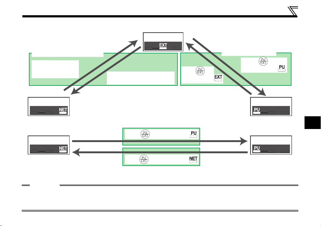
The inverter mounted with a communication option has three operation modes.
(1) PU operation [PU].............. Controls the inverter from the keys of the operation panel on the inverter or
parameter unit (FR-PU07/FR-PA07).
(2) External operation [EXT] ...Controls the inverter by switching ON/OFF external signals connected to
the control circuit terminals of the inverter.
(The inverter is factory-set to this mode.)
(3) Network operation [NET] ... Controls the inverter with instructions from the network via the
communication option.
(The operation signal and running frequency can be entered from the
control circuit terminals depending on the Pr. 338 Communication operation
command source and Pr. 339 Communication speed command source settings.
Refer to page 25.)
4.2.1 Operation mode indicator
Operation panel
Operation mode indicators
(The inverter operates according to the LED lit mode.
PU: PU operation mode
EXT: External operation mode
NET: Network operation mode
20

INVERTER SETTING
4
4.2.2
(1) Operation mode switching conditions
Before switching the operation mode, check that:
1) The inverter is at a stop;
2) Both the STF and STR signals are OFF; and
3) The Pr. 79 Operation mode selection setting is correct.
(Set using the operation panel of the inverter or parameter unit (FR-PU07/FR-PA07).)
Refer to the Inverter Manual for details of Pr. 79.
(2) Operation mode selection at power ON and at restoration from instantaneous power
The operation mode at power ON and at restoration from instantaneous power failure can be selected.
Set a value other than "0" in Pr. 340 to select the Network operation mode.
After started in Network operation mode, parameter write from the network is enabled. (Refer to page 76 for
a program example for parameter write.)
REMARKS
• Change of the Pr. 340 setting is applied valid power ON or an inverter reset.
• Pr. 340 can be changed with the operation panel in any operation mode.
Operation mode switching and communication startup mode (Pr. 79, Pr. 340)
failure
21
INVERTER SETTING
Pr. 340
Setting
(initial
value)
10
Pr. 79
Setting
0 (initial
value)
0
3, 4 External/PU combined operation mode Operation mode switching is disallowed
1
3, 4 External/PU combined operation mode
3, 4 External/PU combined operation mode Same as when Pr. 340 = "0"
Operation Mode at Power ON or Power
External operation mode
1 PU operation mode PU operation mode fixed
2 External operation mode
6 External operation mode
X12 (MRS) signal ON
7
X12 (MRS) signal OFF
0 NET operation mode
1 PU operation mode
NET operation mode
2
NET operation mode
6
X12 (MRS) signal ON .... NET operation mode
7
X12 (MRS) signal OFF
0 NET operation mode Switching between the PU and NET operation mode is enabled *2
1 PU operation mode Same as when Pr. 340 = "0"
2
NET operation mode NET operation mode fixed
NET operation mode
6
7 External operation mode Same as when Pr. 340 = "0"
Restoration
..... External operation mode
... External operation mode
... External operation mode
Switching among the External, PU, and NET operation mode is
*1
enabled
Switching between the external and NET operation mode is enabled
Switching to the PU operation mode is disallowed
Switching among the External, PU, and NET operation mode is
enabled while running.
Switching among the External, PU, and NET operation mode is enabled
External operation mode fixed (Forcibly switched to External
operation mode.)
Same as when Pr. 340 = "0"
Switching between the PU and NET operation mode is enabled while
*2
running
Operation Mode Switchover
*1 Operation mode cannot be directly changed between the PU operation mode and Network operation mode.
*2 Operation mode can be changed between the PU operation mode and Network operation mode with of the operation panel and
X65 signal.
*1
22
4
(3) Operation mode switching method
INVERTER SETTING
When "0 or 1" is set in Pr. 340
Switching through the network
Switch to External
operation mode
through the network.
Network operation PU operation
Switch to Network operation
mode through the network.
When "10" is set in Pr. 340
Network operation PU operation
For the switching method with the external terminal, refer to the Inverter Manual.
Refer to page 61 for the switching method through the network.
External operation
Press on
the PU to light
Press on the PU to light
Press on the PU to light
Switching with the PU
Press on
the PU to light
CAUTION
• When starting the inverter in Network operation mode at power ON or an inverter reset, set a value other
than "0" in Pr. 340. (Refer to page 21)
• When setting a value other than "0" in Pr. 340, make sure that the initial settings of the inverter are correct.
23
 Loading...