

Mitsubishi Electric FR-A7NCA Instruction Manual

INVERTER
Plug-in option
PRE-OPERATION INSTRUCTIONS
1
FR-A7NCA
INSTRUCTION MANUAL
communication function
INSTALLATION
WIRING
INVERTER SETTING
FUNCTIONS
CANopen DEFINITIONS
SERVICE
OBJECT DICTIONARY
TROUBLESHOOTING
2
3
4
5
6
7
8
9
Thank you for choosing this Mitsubishi Inverter plug-in option.
This instruction manual gives handling information and
precautions for use of this equipment. Incorrect handling might
cause an unexpected fault. Before using the equipment, please
read this manual carefully to use the equipment to its optimum.
Please forward this manual to the end user.
This section is specifically about
safety matters
Do not attempt to install, operate, maintain or inspect this
product until you have read through this instruction manual and
appended documents carefully and can use the equipment
correctly. Do not use this product until you have a full
knowledge of the equipment, safety information and
instructions.
In this instruction manual, the safety instruction levels are
classified into "WARNING" and "CAUTION".
Assumes that incorrect handling may
WARNING
CAUTION
Note that even the level may lead to a serious
consequence according to conditions. Please follow the
instructions of both levels because they are important to
personnel safety.
cause hazardous conditions, resulting
in death or severe injury.
Assumes that incorrect handling may
cause hazardous conditions, resulting
in medium or slight injury, or may
cause physical damage only.
CAUTION
SAFETY INSTRUCTIONS
1. Electric Shock Prevention
WARNING
• While power is on or when the inverter is running, do not
open the front cover. You may get an electric shock.
• Do not run the inverter with the front cover or wiring cover
removed. Otherwise, you may access the exposed highvoltage terminals and charging part and get an electric shock.
• If power is off, do not remove the front cover except for wiring
or periodic inspection. You may access the charged inverter
circuits and get an electric shock.
• Before starting wiring or inspection, check to make sure that
the indication of the inverter operation panel is off, wait for at
least 10 minutes after the power supply has been switched off,
and check that there are no residual voltage using a tester or
the like. The capacitor is charged with high voltage for some
time after power off and it is dangerous.
• Any person who is involved in the wiring or inspection of this
equipment should be fully competent to do the work.
• Always install the plug-in option before wiring. Otherwise,
you may get an electric shock or be injured.
• Do not touch the plug-in option with wet hands. Otherwise
you may get an electric shock.
• Do not subject the cables to scratches, excessive stress,
heavy loads or pinching. Otherwise you may get an electric
shock.
A-1
2. Injury Prevention
3) Usage
CAUTION
• Apply only the voltage specified in the instruction manual to
each terminal. Otherwise, burst, damage, etc. may occur.
• Ensure that the cables are connected to the correct terminals.
Otherwise, burst, damage, etc. may occur.
• Always make sure that polarity is correct to prevent damage, etc.
Otherwise, burst, damage may occur.
• While power is on or for some time after power-off, do not touch
the inverter as it is hot and you may get burnt.
3. Additional Instructions
Also note the following points to prevent an accidental failure,
injury, electric shock, etc.
1) Transportation and mounting
CAUTION
• Do not install or operate the plug-in option if it is damaged or
has parts missing.
• Do not stand or rest heavy objects on the product.
• Check that the mounting orientation is correct.
• Prevent other conductive bodies such as screws and metal
fragments or other flammable substance such as oil from
entering the inverter.
2) Trial run
CAUTION
• Before starting operation, confirm and adjust the parameters.
A failure to do so may cause some machines to make
unexpected motions.
WARNING
• Do not modify the equipment.
• Do not perform parts removal which is not instructed in this
manual. Doing so may lead to fault or damage of the inverter.
CAUTION
• When parameter clear or all parameter clear is performed,
reset the required parameters before starting operations.
Each parameter returns to the initial value.
• For prevention of damage due to static electricity, touch
nearby metal before touching this product to eliminate static
electricity from your body.
4) Maintenance, inspection and parts replacement
CAUTION
• Do not test the equipment with a megger (measure insulation
resistance).
5) Disposal
CAUTION
• Treat as industrial waste.
6) General instruction
All illustrations given in this manual may have been drawn with
covers or safety guards removed to provide in-depth
description. Before starting operation of the product, always
return the covers and guards into original positions as specified
and operate the equipment in accordance with the manual.
A-2

CONTENTS
1 PRE-OPERATION INSTRUCTIONS 1
1.1 Unpacking and Product Confirmation .............................................................................................1
1.1.1 Packing confirmation ......................................................................................................................................3
1.1.2 Parts ...............................................................................................................................................................4
1.2 STATUS LED (operation status indication) .....................................................................................5
1.3 Specifications.....................................................................................................................................6
2 INSTALLATION 7
2.1 Pre-Installation Instructions .............................................................................................................7
2.2 Installation of the Communication Option LED Display Cover .....................................................7
2.3 Installation Procedure .......................................................................................................................8
2.4 Node Address Setting .....................................................................................................................10
3 WIRING 11
3.1 Connection to Network....................................................................................................................11
3.2 Wiring................................................................................................................................................12
4 INVERTER SETTING 14
4.1 Parameter List ..................................................................................................................................14
4.2 Parameter for CANopen communication.......................................................................................15
I

4.2.1 CANopen address (Pr. 347) .........................................................................................................................15
4.2.2 CANopen baud rate (Pr. 348).......................................................................................................................16
4.3 Operation Mode Setting ..................................................................................................................17
4.3.1 Operation mode indication............................................................................................................................17
4.3.2 Operation mode switching and communication startup mode (Pr. 79, Pr. 340) ...........................................18
4.4 Operation and Speed Command Source (Pr. 338, Pr. 339, Pr. 550) ............................................21
4.4.1 Communication EEPROM write selection (Pr. 342).....................................................................................25
4.5 Operation at Communication Error Occurrence...........................................................................26
4.5.1 Operation selection at communication error occurrence (Pr. 500 to Pr. 502) ..............................................26
4.5.2 Alarm and measures ....................................................................................................................................30
4.6 Inverter Reset ...................................................................................................................................32
4.7 Frequency and Speed Conversion Specifications .......................................................................34
5 FUNCTIONS 35
5.1 Output from the Inverter to the Network........................................................................................35
5.2 Input to the Inverter from the Network...........................................................................................35
6 CANopen DEFINITIONS 36
6.1 Communicationmethod..................................................................................................................36
6.2 Message format................................................................................................................................37
6.3 Response Level................................................................................................................................38
6.3.1 Response level of PDO ................................................................................................................................38
6.3.2 Response level of SDO ................................................................................................................................39
II

7 SERVICE 40
7.1 Process Data Object (PDO).............................................................................................................40
7.1.1 Receive PDO................................................................................................................................................40
7.1.2 Transmit PDO...............................................................................................................................................44
7.2 Service Data Object (SDO) ..............................................................................................................48
7.2.1 SDO Upload (SDO read)..............................................................................................................................48
7.2.2 SDO Download (SDO write).........................................................................................................................50
7.2.3 SDO Abort Code (SDO error code)..............................................................................................................52
7.3 SYNC Object.....................................................................................................................................54
7.3.1 Bus Synchronization and Sampling..............................................................................................................54
7.3.2 Bus Synchronization and Actual...................................................................................................................56
7.4 Emergency object ............................................................................................................................58
7.5 Network Management object (NMT) ...............................................................................................60
7.5.1 Status transition of NMT state......................................................................................................................60
7.5.2 Status transition matrix of NMT state ...........................................................................................................61
7.5.3 Module Control Service ................................................................................................................................62
7.5.4 Error Control Service....................................................................................................................................63
8 OBJECT DICTIONARY 67
8.1 Object List ........................................................................................................................................67
8.2 Object Detail of Communication Profile Area ...............................................................................71
8.2.1 (Index 1000h) Device Type ..........................................................................................................................71
8.2.2 (Index 1001h) Error Register........................................................................................................................72
III

8.2.3 (Index 1002h) Manufacturer Status Register................................................................................................73
8.2.4 (Index 1005h) COB-ID SYNC.......................................................................................................................74
8.2.5 (Index 1008h) Manufacturer Device Name...................................................................................................75
8.2.6 (Index 100Ch) Guard Time...........................................................................................................................75
8.2.7 (Index 100Dh) Life Time Factor....................................................................................................................76
8.2.8 (Index 1010h) store parameters...................................................................................................................77
8.2.9 (Index 1011h) restore default parameters ....................................................................................................79
8.2.10 (Index 1014h) COB-ID EMCY ......................................................................................................................80
8.2.11 (Index 1015h) Inhibit Time EMCY ................................................................................................................81
8.2.12 (Index 1017h) Producer Heartbeat Time......................................................................................................81
8.2.13 (Index 1018h) Identity...................................................................................................................................82
8.2.14 (Index 1400h to 15FFh) Recive PDO Parameters........................................................................................84
8.2.15 (Index 1600h to 17FFh) Recive PDO Mapping ............................................................................................86
8.2.16 (Index 1800h to 19FFh) Transmit PDO Parameters.....................................................................................87
8.2.17 (Index 1A00 to 1BFFh)Transmit PDO Parameters.......................................................................................90
8.3 Object Detail of Manufacturer Specific Area .................................................................................91
8.3.1 (Index 2000h to 2063h) Monitor of the inverter ............................................................................................91
8.3.2 (Index 2106h) Alarm clear ............................................................................................................................94
8.3.3 (Index 2107h) Inverter reset.........................................................................................................................94
8.3.4 (Index 2108h) Parameter Clear....................................................................................................................95
8.3.5 (Index 2109h) Operation Mode.....................................................................................................................96
8.3.6 (Index 3000h to 3385h, 33ACh to 33E7h) Normal Parameter Area.............................................................97
8.3.7 (Index 3386h to 33ABh) Calibration Parameter Area...................................................................................98
8.3.8 (Index 3400h to 3403h) Alarm history 1 to 8 ................................................................................................99
8.3.9 (Index 4000h) Control input command (w) / Inverter status (r)...................................................................101
8.3.10 (Index 4001h) Set frequency (Set Speed) (w) /
Output frequency (Running speed) (r)........................................................................................................103
IV

8.3.11 (Index 4002h) Set Frequency.....................................................................................................................105
8.3.12 (Index 4003h) Set Speed............................................................................................................................106
8.3.13 (Index 4010h) Control Input Command (w) ................................................................................................107
8.3.14 (Index 4011h) Inverter Status (r) ................................................................................................................108
8.3.15 (Index 4012h) Set Frequency (w) / Set Speed (w) .....................................................................................109
8.3.16 (Index 4013h) Output Frequency (r) / Running Speed (r)...........................................................................110
8.4 Object detail of Device Profile Area .............................................................................................111
8.4.1 (Index 6040h) controlword..........................................................................................................................111
8.4.2 (Index 6041h) Statusword ..........................................................................................................................114
8.4.3 (Index 6042h) vl_target_velocity.................................................................................................................116
8.4.4 (Index 6043h) vl_velocity_demand.............................................................................................................116
8.4.5 (Index 6044h) vl_control_effort...................................................................................................................117
8.4.6 (Index 6046h) vl_velocity_min_max_amount .............................................................................................118
8.4.7 (Index 6048h) vl_velocity_acceleration ......................................................................................................120
8.4.8 (Index 6049h) vl_velocity_deceleration ......................................................................................................123
8.4.9 (Index 604Ah) vl_velocity_quick_stop ........................................................................................................125
8.4.10 (Index 605Ah) Quick_stop_option_code ....................................................................................................127
8.4.11 (Index 6060h) modes_of_operation............................................................................................................128
8.4.12 (Index 6061h) modes_of_operation_display ..............................................................................................129
8.4.13 (Index 67FFh) Single_Device_Type...........................................................................................................130
9 TROUBLESHOOTING 131
APPENDIX 132
EDS file ...........................................................................................................................................132
V

1 PRE-OPERATION INSTRUCTIONS
1.1 Unpacking and Product Confirmation
Take the plug-in option out of the package, check the unit name, and confirm that the product is as you
ordered and intact.
This product is a plug-in option for the FR-A700 series inverter assembled in and after July 2006.
Check the SERIAL number printed on the rating plate or the Serial number sticker of the inverter or
package and check that the first three digits of the SERIAL number is the number in the table next page.
SERIAL number check
z
(1) For the FR-A740-00023 to 00620-EC
Refer to the inverter manual for the position of the rating plate.
Rating plate example
Symbol Year Month Control number
The SERIAL consists of 1 version symbol, 2 numeric
characters or 1 numeric character and 1 alphabet letter
indicating year and month, and 6 numeric characters
indicating control number.
Month is indicated as 1 to 9, X (October), Y (November),
and Z (December).
6 7 {{{{{{
SERIAL (Serial No.)
1
1
PRE-OPERATION INSTRUCTIONS
(2) For the FR-A740-00770 to 12120-EC
Check the SERIAL indicated on the Serial number sticker shown below.
Serial number sticker example
FR-CA70-EC 67
SERIAL
Symbol
Yea r
Month
Control unit type
SERIAL (Serial No.)
The SERIAL consists of 1 version symbol, 2 numeric
characters or 1 numeric character and 1 alphabet letter
indicating year and month, and 3 numeric characters
indicating control number.
Month is indicated as 1 to 9, X (October), Y (November),
and Z (December).
• To check the SERIAL, the front cover must be removed.
For the removal of the front cover, refer to the inverter manual.
Compatible SERIAL number list
z
Type SERIAL (the first three digits)
FR-A740-00023 to 00620-EC E67 or later
FR-A740-00770 to 12120-EC D67 or later
2
VUW
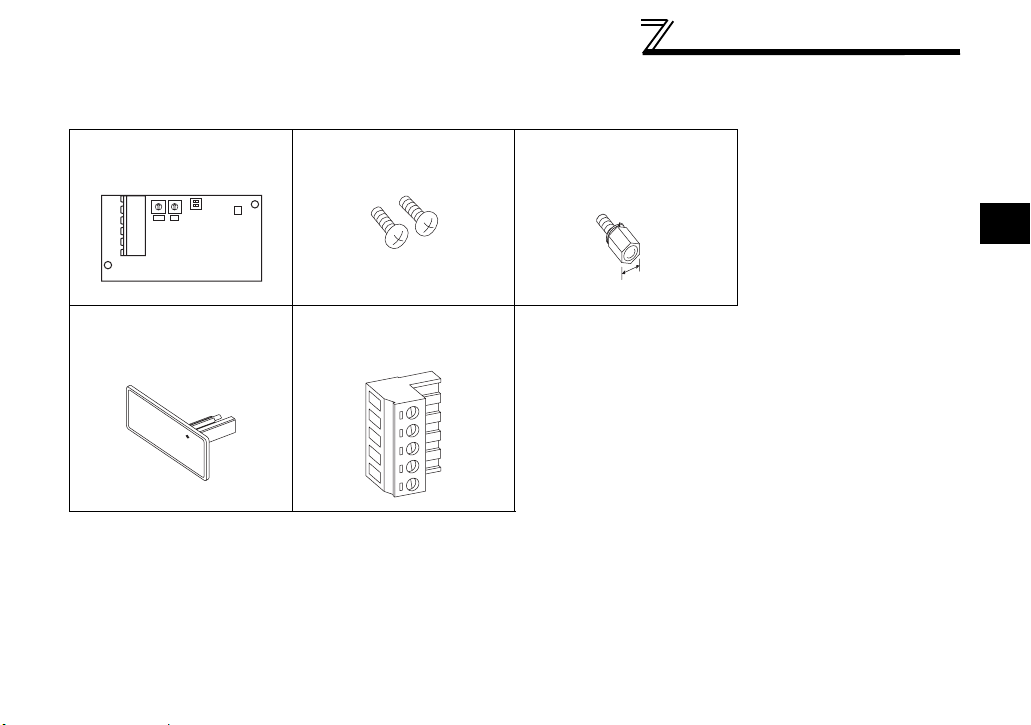
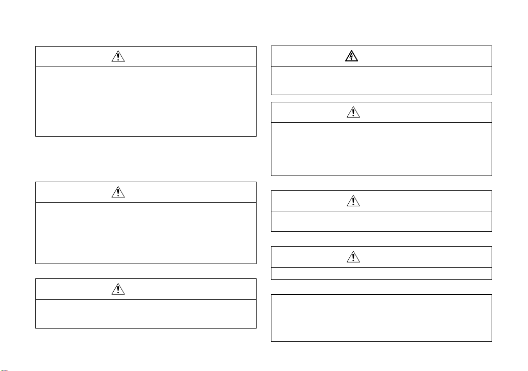
1.1.1 Packing confirmation
Check the enclosed items.
Plug-in option
......................................... 1
0
0
1
1
F
F
2
2
E
E
3
3
D
D
4
4
C
C
5
5
6
6
B
B
7
7
A
A
8
8
9
9
X16 X1
Mounting screw (M3 × 6mm)
.............. 2 (Refer to page 8.)
PRE-OPERATION INSTRUCTIONS
Hex-head screw for option
mounting (5.5mm)
...............1 (Refer to page 8.)
1
5.5mm
Communication option LED
display cover
.............. 1 (Refer to page 7.)
Terminal block
.............1 (Refer to page 12.)
CANopen is a registered trademark of CiA (CAN in
Automation).
3
PRE-OPERATION INSTRUCTIONS
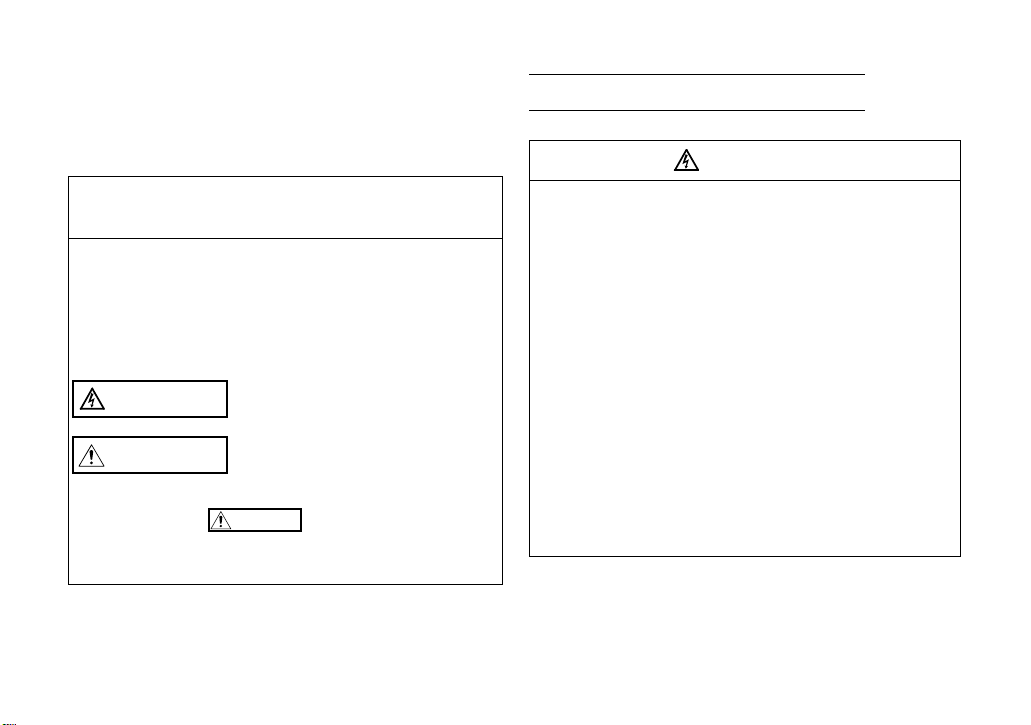
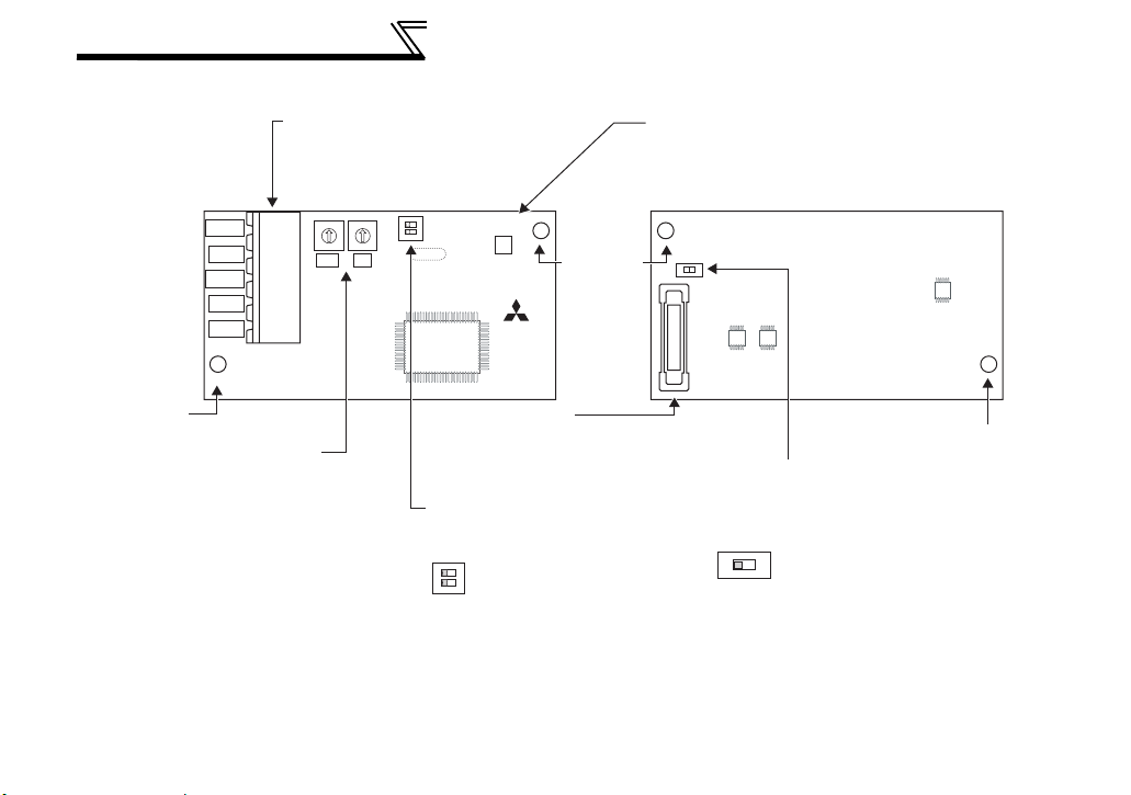
1.1.2 Parts
Connector for communication
Mount the accessory terminal
block to connect to the network.
Front view Rear view
0
0
1
1
F
F
2
2
E
E
3
CAN_GND
CAN_L
CAN_SHLD
CAN_H
CAN_V+
3
D
D
4
4
C
C
5
5
6
6
B
B
7
7
A
A
8
8
9
9
SW1 SW2
X16 X1
SW3
STATUS LED (operation status indication)
Lit/flicker/off of the LED indicate inverter
operation status.
O
1
F
2
F
LED1
2
1
STATUS LED
FR-A7NCA
Mounting
hole
SW4
(Refer to page 5.)
Mounting
hole
4
Node address switch
Set the node address.
(Refer to page 10.)
Connector
Connect to the inverter
option connector.
Switch for manufacturer setting
Do not change from initially-set
status (1, 2:OFF).
O
1
F
2
F
Mounting hole
Switch for manufacturer setting
Do not change from initially-set
status (OFF).
SW4
O
B
5
N
PRE-OPERATION INSTRUCTIONS
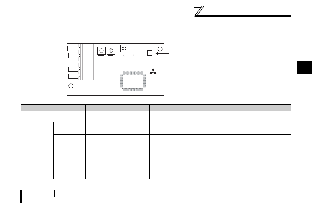
1.2 STATUS LED (operation status indication)
STATUS LED indicates the operating status of the option unit according to the indication status of LED
(RUN, ERR).
O
0
1
F
2
E
CAN_GND
CAN_L
3
D
4
C
5
6
B
7
A
8
9
SW1 SW2
X16 X1
CAN_SHLD
CAN_H
CAN_V+
Indicates network status and error status of the device.
LED indication status Status Description
Power OFF/Reset Hold
Without error
Green
(RUN)
Off
Single flash "STOPPED" The network status of the device is "Stopped"
Blinking "PRE-OPERATIONAL" The network status of the device is "Pre-Operational"
On "OPERATIONAL" The network status of the device is "Operational"
Single flash Warning
Red
(ERR)
Double flash
Error control event
occurrence
On Bus off Bus off state occured to the CAN chip.
* When checked through a lens for the LED display cover, Red and Green alternately displayed (Double flash of Red during
Green is lit) is observed depending on the operating status. Red indicates error status and Green indicates operating status.
REMARKS
Refer to page 60 for network status.
1
0
1
F
2
E
F
3
D
4
2
F
C
5
SW3
6
B
7
A
8
9
LED1
2
1
STATUS LED
FR-A7NCA
STATUS LED
Green: Indicates operating status
Red: Indicates error status
Power of the device is OFF. Or reset held status.
The inverter functions properly.
A network error such as a communication frame error has
occured and a warning was given from a CAN chip.
(error passive status)
Error control event has occurred.
· Guard message send
· Heartbeat message receive
1
5

PRE-OPERATION INSTRUCTIONS
1.3 Specifications
(1) Communication specifications
Item Description
Topology Bus
Communication speed 10Kbps to 1Mbps
Transmission distance 25m(1M) to 2500m(10k)
Number of node 127
Communication method PeerToPeer, broad cast
EDS file With
* A bridge or repeater is necessary when the transmission distance is 1000m or more.
(2) List of communication service (function)
Item Description
NMT Slave
Error Control Node Guarding, Heartbeat (either can be selected at configuration)
Node ID setting Switch, parameter
Number of PDO RPDO × 3, TPDO × 3
Event Driven
PDO mode
PDO Linking Possible
PDO Mapping Impossible (Static)
Emergency message With
Application layer CiA DS301 V4.01
Profile CiA DSP402 V2.0
Timer Driven
Sync
Remote Request
*
6
2 INSTALLATION
2.1 Pre-Installation Instructions
Make sure that the input power of the inverter is off.
CAUTION
With input power on, do not install or remove the plug-in option. Otherwise, the inverter and
plug-in option may be damaged.
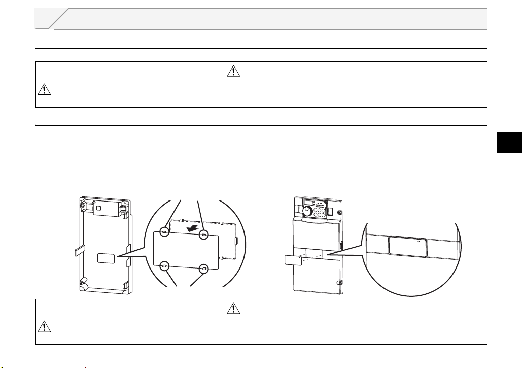
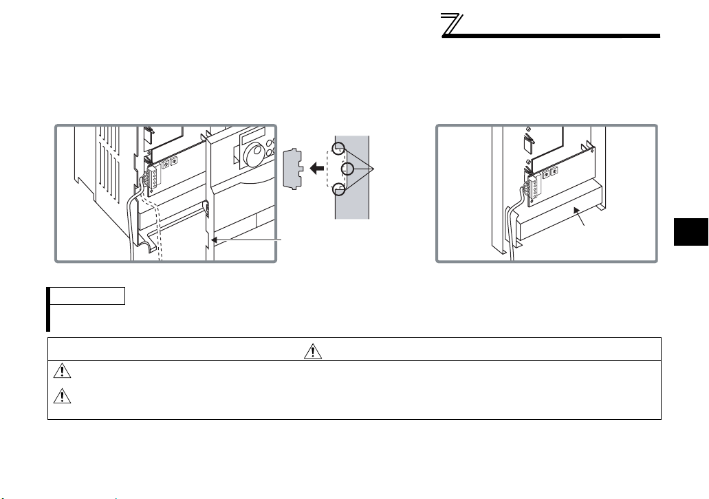
2.2 Installation of the Communication Option LED Display Cover
Mount the cover for displaying the operation status indication LED for the communication option on the
inverter front cover.
1)
Cut off hooks on the rear of the inverter front
cover with nipper, etc. and open a window for
fitting the LED display cover.
Cut off with a nipper, etc.
Cut off with a nipper, etc.
CAUTION
2)
Fit the communication option LED display
cover to the front of the inverter front cover
and push it into until fixed with hooks.
Fit it so that the position of
lenses is in the upper-right
of the LED display cover.
Fitting drawing
2
Take care not to hurt your hand and such with portions left by cutting hooks of the rear of the
front cover.
7
INSTALLATION
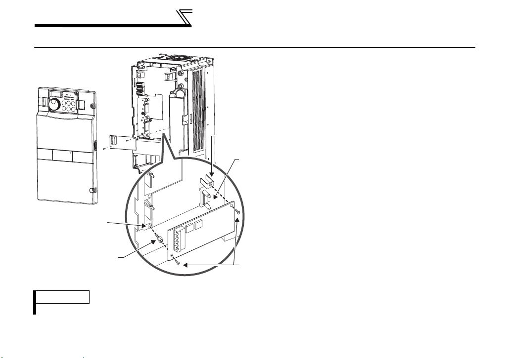
2.3 Installation Procedure
1) Remove the inverter front cover.
1)
Screw hole for
option mounting
Inverter side
option
connector
3)
Screw hole for
option mounting
(on earth plate)
Hex-head screw
for option mounting
REMARKS
After removing two screws on the right and left places, remove the plug-in option.
2)
4)
Mounting
screws
2) Mount the hex-head screw for option
mounting into the inverter screw hole
(on earth plate). (size 5.5mm,
tightening torque 0.56N⋅m to 0.75N⋅m)
3) Securely fit the connector of the plug-in
option to the inverter connector along
the guides.
4) Securely fix the both right and left sides
of the plug-in option to the inverter with
the accessory mounting screws. If the
screw holes do not line-up, the
connector may not have been plugged
snugly. Check for loose plugging.
8
INSTALLATION
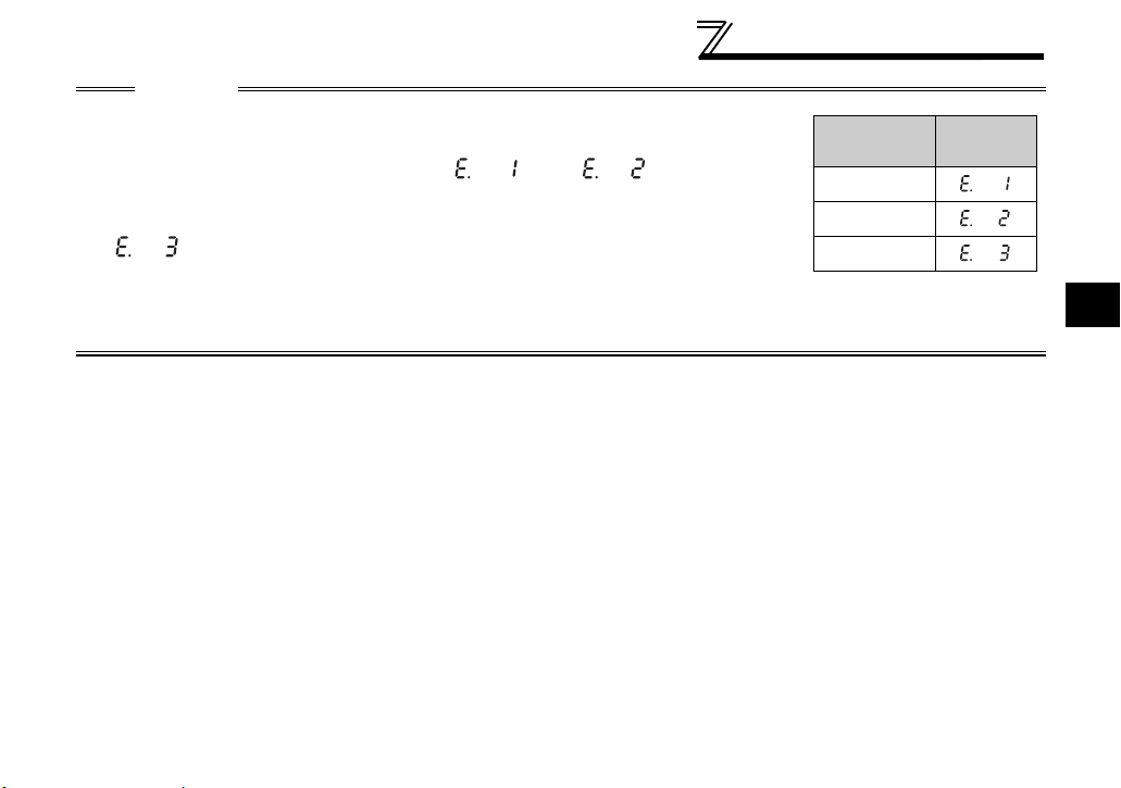
CAUTION
• When using this option unit, mount it in the "option connector 3 (lowermost
connector)" of the inverter.
If it is fitted in option connector 1 or 2, " " or " " (option alarm)
is displayed and the inverter will not function. In addition, when the inverter can
not recognize that the option is mounted due to improper installation, etc.,
" " (option alarm) is displayed even if the option is fitted in the option
connector 3.
• Take care not to drop a hex-head screw for option mounting or mounting screw
during mounting and removal.
• Pull out the option straight to remove. Otherwise, the connector may be damaged by some applied force.
Mounting
Position
Connector 1
Connector 2
Connector 3
Error
Display
2
9

INSTALLATION
2.4 Node Address Setting
(1) Setting with node address switch
Set the node address between "1 to 127(7Fh)" using node address switches on the FR-A7NCA (refer to
page 4).
The setting is reflected when power turns on next or the inverter is reset.
Set the node address switch to node address (SW1 setting × 16 + SW2 setting).
Set Pr.347 CANopen address to "0 (initial value)".
Set the arrow (×) of the corresponding switches to the number to set a desired address.
z Setting example
0
0
1
1
F
Node address 1:
Set the "×" of SW1 to "0" and the "×" of
SW2 to "1".
F
2
E
3
D
4
C
5
B
6
7
A
8
9
X16 X1
CAUTION
1. Set the node address switch to the switch number position correctly. If the switch
is set between numbers, normal data communication can not be made.
2. When the node address switch is set to values other than "1 to 127", they are
regarded as "127".
(2) Set with parameter (Pr. 347)
Use parameter (Pr. 347) of the inverter to set. Setting node address with parameter makes the node
address switch setting invalid. The setting is reflected at the next power-on or inverter reset. (Refer to
page 15)
Node address 127:
2
E
3
D
4
C
5
B
6
7
A
Set the "×" of SW1 to "7" and the "×" of
8
9
SW2 to "F".
Good
example
0
1
F
2
E
3
D
4
5
C
6
B
7
A
8
9
0
1
F
2
E
E
3
D
D
4
C
C
5
B
B
6
7
A
8
9
X16 X1
Bad
example
0
1
F
2
E
3
D
4
5
C
6
B
7
A
8
9
0
1
F
2
3
4
5
6
7
A
8
9
10
3 WIRING
3.1 Connection to Network
(1) Be sure to check the following before connecting the inverter to the network.
· Check that the FR-A7NCA is snugly inserted into the inverter. (Refer to page 7.)
· Check that the correct node address is set. (Refer to page 10.)
· Check that a drop cable is firmly connected to the FR-A7NCA. (Refer to page 12.)
(2) Make sure that the terminating resistor is installed at each end (between CAN_H and CAN_L) of the
trunk cable. These resistors must meet the following requirements.
Requirements of Terminating Resistors
R (resistance value) = 124Ω 1% metal film 0.25 W
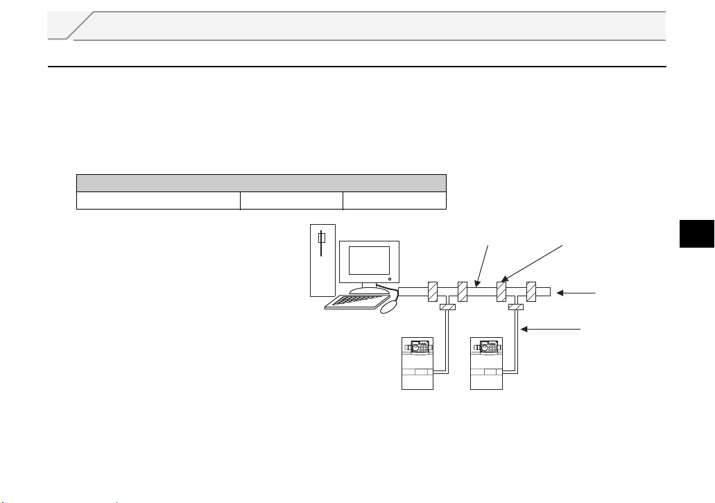
(3) Connect drop cables to the trank
cable.
· If the trunk connector is a
CANopen sanctioned pluggable or
sealed connector, the connection
to the active network can be made
at any time whether the inverter is
on or off. The option unit
automatically detects when the
connection is completed.
· If connecting to the network with
free wires, power to the network
and inverter should be shut off as a safety precaution in case two or more signal wires are
accidentally shorted together.
Trunk cable
InverterInverter
Trunk connector
Terminating
resistor
Drop cable
3
11

WIRING
3.2 Wiring
(1) Strip the insulation back about 40mm on the free wire end of the drop cable to expose the four colored
signal wires and the silver shield wire.
(2) Strip the insulation back of each signal cable to use. If the length of the sheath pealed is too long, a
short circuit may occur among neighboring wires. If the length is too short, wires might come off.
Cable stripping size
7mm
(3) Loosen the terminal screw and insert the cable into the terminal
according to the terminal arrignment.
Tighten each cable with fixing screws to the recommended tightening torque.
Screw Size
M3
CAUTION
Undertightening can cause cable disconnection or malfunction. Overtightening can cause a short circuit
or malfunction due to damage to the screw or unit.
(4) Connect the terminal block to the connector for communication of
the communication option mounted on the inverter.
Wire the stripped cable after twisting it to prevent it from becoming loose.
In addition, do not solder it.
Use a bar type terminal as required.
CAN_GND (black)
CAN_L (blue)
Shielded cable
Tightening Torque
0.5N•m to
0.6N•m
Cable Size Screwdriver
2
0.3mm
0.75mm
Small flat-blade screwdriver
to
(Tip thickness: 0.4mm/tip
2
width: 2.5mm)
CAN_H (white)
CAN_V+ (red)
Terminal layout
12
WIRING
C
(5) For wiring of FR-A740-00620-EC or less, route wires between the control circuit terminal block and front
cover. If cables can not be routed between the control circuit terminal block and front cover (approx 7mm),
remove a hook of the front cover and use a space become available.
For wiring of FR-A740-00770-EC or more, use the space on the left side of the control circuit terminal
block.
1
2
0
3
9
4
8
1
5
7
2
0
6
3
9
4
8
5
7
6
Cut off
with a
nipper,
etc.
1
2
0
3
9
4
8
1
5
7
2
0
6
3
9
4
8
5
7
6
Cut off a hook on the inverter
front cover side surface.
(Cut off so that no portion is left.)
Control circuit
terminal block
FR-A740-00620-EC or less FR-A740-00770-EC or more
REMARKS
⋅ When the hook of the inverter front cover is cut off for wiring, the protective structure (JEM1030) changes to open
type (IP00).
AUTION
When performing wiring using the space between the inverter front cover and control circuit
terminal block, take care not to subject the cable to stress.
After wiring, wire offcuts must not be left in the inverter. They may cause an error, failure or
malfunction.
3
13

4 INVERTER SETTING
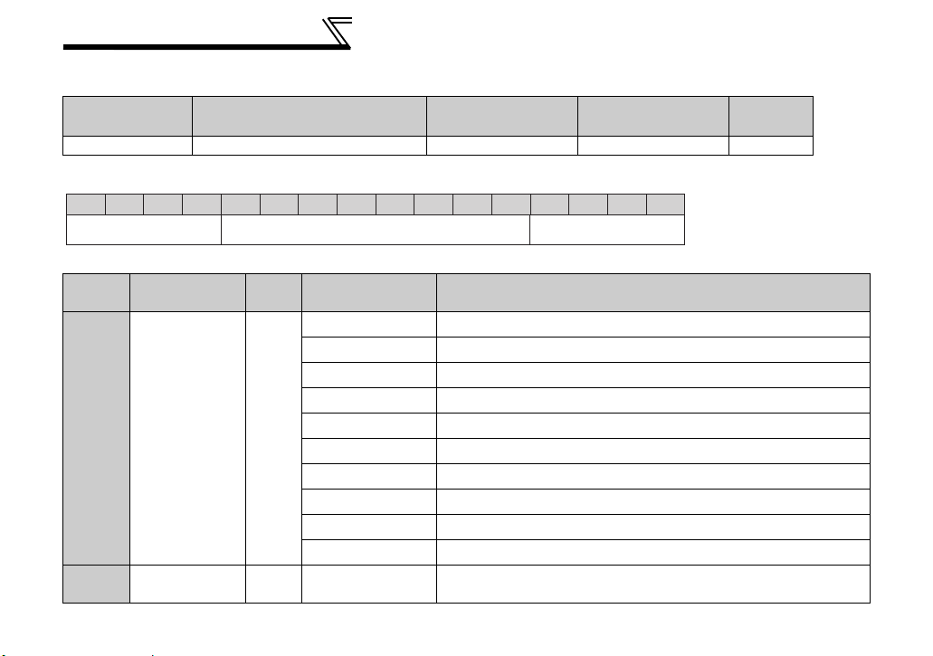
4.1 Parameter List
The following parameters are used for the communication option (FR-A7NCA)
Set the values according to need.
Parameter
Number
79 Operation mode selection 0 to 4, 6, 7 1 0 18
338
339 Communication speed command source 0, 1, 2 1 0 21
340 Communication startup mode selection 0, 1, 2, 10, 12 1 0 18
342 Communication EEPROM write selection 0, 1 1 0 25
347
348 * CANopen baud rate 0 to 4095 1 4 16
349
500
501
502
550 NET mode control source selection 0, 1, 9999 1 9999 21
* Parameters which can be displayed when the plug-in option (FR-A7NCA) is mounted.
Communication operation command
source
* CANopen address 0 to 4095 1 0 15
* Communication reset selection 0, 1 1 0 33
Communication error recognition waiting
*
time
Communication error occurrence count
*
display
Stop mode selection at communication
*
error
Name Setting Range
0, 1 1 0 21
0 to 999.8s 0.1s 0 26
01027
0, 1, 2, 3 1 0 28
Minimum
Setting
Increments
Initial
Value
Refer to
Page
14
INVERTER SETTING
4.2 Parameter for CANopen communication
CANopen communication can be set by the inverter parameter.
Parameter setting is made valid after inverter reset (turning the power off and turning the RES signal on).
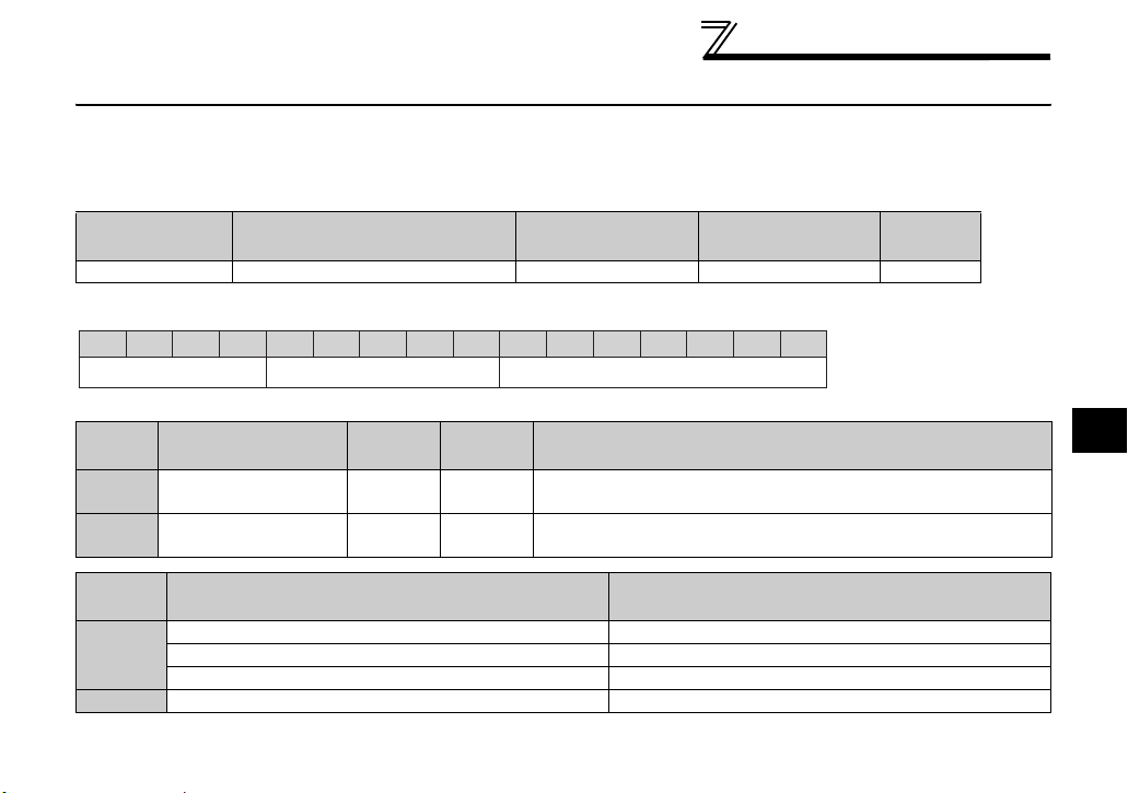
4.2.1 CANopen address (Pr. 347)
Parameter
Number
347 CANopen Address 0 to 4095 1 0
Name Setting Range
Minimum Setting
Increments
Node address can be set using Pr.347.
Address Key Node Address
* A value set is ignored.
Bit Item
0 to 6 Node Address 0 0 to 127
12 to 15 Address Key 0 0
Pr.347
setting
0
1 to 127
Not Available*
Initial
Val ue
Setting
Range
Definition
Node Address of device is set between 1 to 127.
Set "0" (initial value) to set node address with node address switch.
Set "0" always. When a value other than "0"is set, the inverter
operates as when "0" (initial value) is set in Pr. 345.
Node Address Switch Node Address
0 127
1 to 127(7Fh) Switch setting
128(80h) or more 127
The
Pr.347
setting is valid regardless of the switch setting.
Initial
Value
0123456789101112131415
4
15
INVERTER SETTING
4.2.2 CANopen baud rate (Pr. 348)
Parameter
Number
348 CANopen baud rate 0 to 4095 1 4
Name Setting Range
Minimum Setting
Increments
Baud rate of CANopen communication can be set using Pr.348.
Baud Rate Key Baud Rate
* A value set is ignored.
Bit Item
0 to 3 Baud Rate 4
12 to 15 Baud Rate Key 0 0
Initial
Value
Not Available*
Setting Range Definition
01Mbps
1 800kbps
2 500kbps
3 250kbps
4 125kbps (Initial value)
5
6 50kbps
7 20kbps
8 10kbps
9 to 15
Setting can not be made (operates as when an initial value is set)
Setting can not be made (operates as when an initial value is set)
Set "0" always. When a value other than "0"is set, the inverter
operates as when "0" (initial value) is set in Pr. 348.
Initial
Val ue
0123456789101112131415
16

INVERTER SETTING
4.3 Operation Mode Setting
The inverter mounted with a communication option has three operation modes.
(1) PU operation [PU].............. Controls the inverter from the key of the operation panel (FR-DU07)
mounted on the inverter.
(2) External operation [EXT] ... Controls the inverter by switching on/off external signals connected to the
control circuit terminals of the inverter.
(The inverter is factory-set to this mode.)
(3) Network operation [NET] ... Controls the inverter with instructions from the network via the
communication option.
(The operation signal and running frequency can be entered from the
control circuit terminals depending on the Pr. 338 Communication operation
command source and Pr. 339 Communication speed command source setting.
Refer to page 22.)
4.3.1 Operation mode indication
FR-DU07
Operation mode indication
(The inverter operates according to the LED lit mode.)
PU: PU operation mode
EXT: External operation mode
NET: Network operation mode
4
17

INVERTER SETTING
4.3.2
Operation mode switching and communication startup mode (Pr. 79, Pr. 340)
(1) Operation mode switching conditions
Before switching the operation mode, check that:
1) The inverter is at a stop;
2) Both the STF and STR signals are off; and
3) The Pr. 79 Operation mode selection setting is correct.
(Set with the operation panel of the inverter.)
Refer to the inverter manual (applied) for details of Pr. 79.
(2) Operation mode selection at power on and at restoration from instantaneous power failure
The operation mode at power on and at restoration from instantaneous power failure can be selected.
Set a value other than "0" in Pr. 340 to select the network operation mode.
After started in network operation mode, parameter write from the network is enabled.
REMARKS
1. Change of the Pr. 340 setting is made valid when powering on or resetting the inverter.
2. Pr. 340 can be changed with the operation panel independently of the operation mode.
18

INVERTER SETTING
Pr. 340
Setting
(initial
value)
1, 2 *2
10, 12
*1 Operation mode can not be directly changed between the PU operation mode and network operation mode.
*2 The Pr. 340 settings "2, 12" are mainly used for communication operation using the inverter RS-485 terminal.
*3 Operation mode can be changed between the PU operation mode and network operation mode with of the operation panel (FR-
Pr. 79
Setting
0 (initial
value)
0
3, 4 External/PU combined operation mode Operation mode switching is disallowed
3, 4 External/PU combined operation mode
*2
3, 4 External/PU combined operation mode Same as when Pr. 340 = "0"
When a value other than "9999" (selection of automatic restart after instantaneous power failure) is set in Pr. 57 Restart coasting time, the
inverter will resume the same operation state which was in before after power has been restored from an instantaneous power failure.
When Pr.340 = "1, 10", a start command turns off if power failure has occurred and then restored during a start command is on.
DU07) and X65 signal.
Operation Mode at Power on or Power
Restoration
External operation mode
1 PU operation mode PU operation mode fixed
2 External operation mode
6 External operation mode
X12 (MRS) signal ON ..... external operation mode Switching among the external, PU, and NET operation mode is enabled
7
X12 (MRS) signal OFF ... external operation mode
0 NET operation mode
1 PU operation mode
2 NET operation mode
6 NET operation mode
X12 (MRS) signal ON .... NET operation mode
7
X12 (MRS) signal OFF ... external operation mode
0 NET operation mode Switching between the PU and NET operation mode is enabled *3
1 PU operation mode Same as when Pr. 340 = "0"
2 NET operation mode NET operation mode fixed
6 NET operation mode
7 External operation mode Same as when Pr. 340 = "0"
Switching among the external, PU, and NET operation mode is
*1
enabled
Switching between the external and Net operation mode is enabled
Switching to the PU operation mode is disallowed
Switching among the external, PU, and NET operation mode is enabled
while running.
External operation mode fixed (Forcibly switched to external
operation mode.)
Same as when Pr. 340 = "0"
Switching between the PU and NET operation mode is enabled while running
Operation Mode Switchover
*1
4
*3
19
INVERTER SETTING
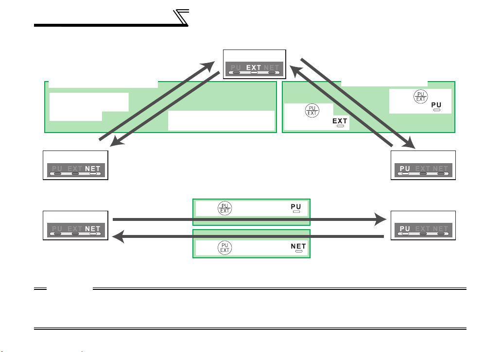
(3) Operation mode switching method
When "0, 1, or 2" is set in Pr. 340
Switching from the network
Switch to the external
operation mode from
the network.
Network operation PU operation
Switch to the network operation
mode from the network.
When "10 or 12" is set in Pr. 340
Network operation PU operation
For the switching method from the external terminal, refer to the inverter manual (applied).
Refer to page 96 for a switching method from the network.
External operation
Press of
the PU to light .
Press of of the PU to light .
Press of of the PU to light .
Switching from the PU
Press of the
PU to light .
CAUTION
⋅ When starting the inverter in network operation mode at powering on or an inverter reset, set a value other than 0 in
Pr. 340. (Refer to page 18)
⋅ When setting a value other than 0 in Pr. 340, make sure that the initial settings of the inverter are correct.
20

INVERTER SETTING
4.4 Operation and Speed Command Source (Pr. 338, Pr. 339, Pr. 550)
(1) Select control source for the network operation mode (Pr. 550)
A control location for the network operation mode can be selected from either the inverter RS-485
terminal or communication option.
When using a communication option, set "0 or 9999 (initial value)" in Pr. 550.
Parameter
Number
550
NET mode operation
command source selection
Name Initial Value
Refer to the inverter manual (applied) for details.
9999
Setting
Range
0
1
9999
Description
Control source of the communication
option is valid
(control source of the inverter RS-485
terminal is invalid)
Control source of the inverter RS-485
terminal is valid
(control source of the communication
option is invalid)
Automatic recognition of the
communication option
Normally, control source of the RS485 terminal is valid. When a
communication option is mounted,
the control source of the
communication option is valid.
4
21

INVERTER SETTING
(2) Selection of control source for the network operation mode (Pr. 338, Pr. 339)
⋅ As control sources, there are operation command source that controls signals related to the start
command and function selection of the inverter and speed command source that controls signals
related to frequency setting.
⋅ In network operation mode, commands from the external terminals and communication are as listed
below.
Control
Location
Selection
Fixed
functions
(Functions
equivalent
to
terminals)
Selective functions
Pr. 178 to Pr. 189 settings
Pr. 338 Communication operation
command source
Pr. 339 Communication speed
Running frequency from communication NET NET NET NET
Terminal 2 External External
Terminal 4 External External
Terminal 1 Compensation
0RL
1RM
2RH
3 RT Second function selection NET External
4 AU Terminal 4 input selection Combined Combined
5 JOG Jog operation selection External
6CS
7 OH External thermal relay input External
8 REX 15-speed selection NET External NET External
9 X9 Third function NET External
10 X10 Inverter operation enable signal External
command source
Low-speed operation command/
remote setting clear
Middle-speed operation command/
remote setting deceleration
High-speed operation command/
remote setting acceleration
Automatic restart after
instantaneous power failure
selection
0:NET
0:NET 1:External
1:
External2:External
NET External NET External
NET External NET External
NET External NET External
0:NET
External
1:
External2:External
Pr. 59 = "0"
(multi-speed)
Pr. 59 = "1, 2"
Pr. 59 = "0"
(multi-speed)
Remarks
(remote)
22
 Loading...