

Mitsubishi Electric FR-A7NC Instruction Manual

INVERTER
Plug-in option
FR-A7NC
INSTRUCTION MANUAL
communication function
HOW TO CHECK FOR ERROR USING THE LEDS
PRE-OPERATION INSTRUCTIONS
1
INSTALLATION
2
WIRING
3
INVERTER SETTING
4
FUNCTION OVERVIEW
5
I/O SIGNAL LIST
6
DETAILS OF INPUT AND OUTPUT
7
PROGRAMMING EXAMPLES
8
9
Thank you for choosing this Mitsubishi Inverter plug-in option.
This instruction manual gives handling information and
precautions for use of this equ ipment. Incorr ect handling might
cause an une xpected fault. Before using the equipment, please
read this manual carefully to use the equipment to its optimum.
Please forward this manual to the end user.
This section is specifically about
safety matters
Do not attempt to install, operate, maintain or inspect this
product until you have read through this instruction manual and
appended documents carefully and can use the equipment
correctly. Do not use this product until you have a full
knowledge of the equipment, safety information and
instructions.
In this instruction manual, the safety instruction levels are
classified into "WARNING" and "CAUTION".
Assumes that incorrect handling may
WARNING
CAUTION
Note that even the level may lead to a se rious
consequence according to conditions. Please follow the
instructions of both levels because they are important to
personnel safety.
cause hazardous conditions, resulting
in death or severe injury.
Assumes that incorrect handling may
cause hazardous conditions, resulting
in medium or slight injury, or may
cause physical damage only.
CAUTION
SAFETY INSTRUCTIONS
1. Electric Shock Prevention
WARNING
• While power is on or when the inverter is running, do not
open the front cover. You may get an electric shock.
• Do not run the inver ter with the front cover or wiring cover
removed. Otherwise, you may access the exposed highvoltage terminals and charging part and get an electric shock.
• If power is off, do not remove the front cover except for wiring
or periodic inspec tion. You may access the char ged inverter
circuits and get an electric shock.
• Before starting wiring or inspection, check to make sure that
the inverter power indicator lamp is off, wait for at least 10
minutes after the power supply has been switched off, and
check that there are no residual voltage using a tester or the
like. The capacitor is charged with high voltage for some time
after power off and it is dangerous.
• Any person who is involved in the wiring or inspection of this
equipment should be fully competent to do the work .
• Always install the plug-in option before wiring. Otherwise,
you may get an electric shock or be injured.
• Do not touch t he plug-in option with wet hands. Otherwise
you may get an electric shock.
• Do not subject the cables to scratches, excessive stress,
heavy loads or pin ching. Otherwise you m ay get an electric
shock.
A-1
2. Injury Prevention
3) Usage
CAUTION
• Apply only the voltage specified in the instruction manual to
each terminal. Otherwise, burst, damage, etc. may occur.
• Ensure that the cables are connected to the correct terminals.
Otherwise, burst, damage, etc. may occur.
• Always make sure that pol arit y is correct to prevent dam age, etc.
Otherwise, burst, damage may occur.
• While power is on or for some time after power-off, do not touch
the inverter as it is hot and you may get burnt.
3. Additional Instructions
Also note the follo wing points to prevent an accidental fail ure,
injury, electric shock, etc.
1) Transportation and mounting
CAUTION
• Do not install or o pe ra te the plug-in op ti on if it is damaged or
has parts missing.
• Do not stand or rest heavy objects on the product.
• Check that the mounting orientation is correct.
• Prevent other conduc tive bodies such as screws and metal
fragments or other flammable substance such as oil from
entering the inverter.
2) Trial run
CAUTION
• Before starting operation, confirm and adjust the parameters.
A failure to do so may cause some machines to make
unexpected motions.
WARNING
• Do not modify the equipment.
• Do not perform parts removal whic h is not instruct ed in this
manual. Doing so may lead to fault or damage of the inverter.
CAUTION
• When parameter clear or all parameter clear is performed,
reset the required parameters before starting operations.
Each parame ter returns to the initial value.
• For prevention of damage due to static electricity, touch
nearby metal before touch ing this produc t to eliminate static
electricity from your bo dy.
4) Maintenance, inspection and parts replacement
CAUTION
• Do not test the equipment with a megger (measure insulation
resistance).
5) Disposal
CAUTION
• Treat as industrial waste.
6) General instruction
All illustrations given in this manual may have been drawn with
covers or safety guards removed to provide in-depth
description. Before starting operation of the product, always
return the covers and guards into original positions as specified
and operate the equipment in accordance with the manual.
A-2

CONTENTS
1 PRE-OPERATION INSTRUCTIONS 1
1.1 Unpacking and Product Confirmation .............................................................................................1
1.1.1 Packing confirmation......................................................................................................................................1
1.1.2 Parts...............................................................................................................................................................2
1.2 Inverter Option Specifications..........................................................................................................3
1.3 CC-Link Version.................................................................................................................................4
1.3.1 CC-Link Ver. 1.10...........................................................................................................................................4
1.3.2 CC-Link Ver. 2................................................................................................................................................4
2 INSTALLATION 5
2.1 Pre-Installation Instructions .............................................................................................................5
2.2 Installation of the communication option LED display cover .......................................................5
2.3 Installation Procedure.......................................................................................................................6
3 WIRING 7
3.1 System Configuration Example........................................................................................................7
3.2 Connection of Several Inverters.......................................................................................................8
3.3 Connection Cable ............................................................................................................................11
3.4 Wiring................................................................................................................................................12
4 INVERTER SETTING 15
4.1 Parameter List..................................................................................................................................15
4.2 Operation Mode Setting ..................................................................................................................16
4.2.1 Operation mode indication............................................................................................................................16
4.2.2 Operation mode switching and communication startup mode (Pr. 79, Pr. 340)...........................................17
I

4.3 Operation and Speed Command Source (Pr. 338, Pr. 339, Pr. 550) ............................................20
4.3.1 Communication EEPROM write selection (Pr. 342).....................................................................................23
4.4 Operation at Communication Error Occurrence...........................................................................24
4.4.1 Operation selection at communication error occurrence (Pr. 500 to Pr. 502) ..............................................24
4.4.2 Alarm and measures....................................................................................................................................28
4.5 Inverter Reset...................................................................................................................................29
4.6 CC-Link function setting .................................................................................................................31
4.6.1 Station number setting (Pr. 542)...................................................................................................................31
4.6.2 Baud rate setting (Pr. 543)........................................................................................................................... 32
5 FUNCTION OVERVIEW 33
5.1 Function Block Diagram..................................................................................................................33
5.2 Output from the Inverter to the Network........................................................................................34
5.3 Input to the Inverter from the Network...........................................................................................35
6 I/O SIGNAL LIST 37
6.1 CC-Link Extended Setting (Pr. 544)................................................................................................37
6.2 I/O Signal List...................................................................................................................................38
6.2.1 I/O signal when CC-Link Ver.1 one station (FR-A5NC compatible) is occupied (Pr. 544 = 0).....................38
6.2.2 I/O signal when CC-Link Ver.1 one station is occupied (Pr. 544 = 1)..........................................................40
6.2.3 I/O signal when CC-Link Ver.2 double setting is selected (Pr. 544 = 12).....................................................41
6.2.4 I/O signal when CC-Link Ver.2 quadruple setting is selected (Pr. 544 = 14)...............................................42
6.2.5 I/O signal when CC-Link Ver.2 octuple setting is selected (Pr. 544 = 18)....................................................43
7 DETAILS OF INPUT AND OUTPUT SIGNALS 45
7.1 Details of Remote Input and Output Signals................................................................................. 45
7.1.1 Output signals (master unit to inverter (FR-A7NC)) .....................................................................................45
7.1.2 Input signals (inverter (FR-A7NC) to master unit)........................................................................................47
7.2 Details of Remote Resister .............................................................................................................49
II

7.2.1 Remote resister (master unit to inverter (FR-A7NC))...................................................................................49
7.2.2 Remote resister (inverter (FR-A7NC) to master unit)...................................................................................52
7.2.3 Instruction codes..........................................................................................................................................55
7.2.4 Monitor codes....................... ...................... ....................... ....................... ....................................................59
8 PROGRAMMING EXAMPLES 61
8.1 Program Example for Reading the Inverter Status.......................................................................64
8.2 Program Example for Setting the Operation Mode.......................................................................65
8.3 Program Example for Setting the Operation Commands ............................................................66
8.4 Program Example for Monitoring the Output Frequency.............................................................67
8.5 Program Example for Parameter Reading.....................................................................................68
8.6 Program Example for Parameter Writing.......................................................................................69
8.7 Program Example for Setting the Running Frequency ................................................................70
8.8 Program Example for Alarm Definition Reading...........................................................................72
8.9 Program Example for Resetting the Inverter at Inverter Error ....................................................73
8.10 Instructions ......................................................................................................................................74
9 HOW TO CHECK FOR ERROR USING THE LEDS 77
9.1 When One Inverter Is Connected ...................................................................................................77
9.2 When Two or More Inverters Are Connected................................................................................79
9.3 Communication Stops During Operation ......................................................................................81
III
1 PRE-OPERATION INSTRUCTIONS
1.1 Unpacking and Product Confirmation
Take the plug-in option out of the package, check the unit name, and confirm that the product is as you
ordered and intact.
This product is a plug-in option dedicated for the FR-F
1.1.1 Packing confirmation
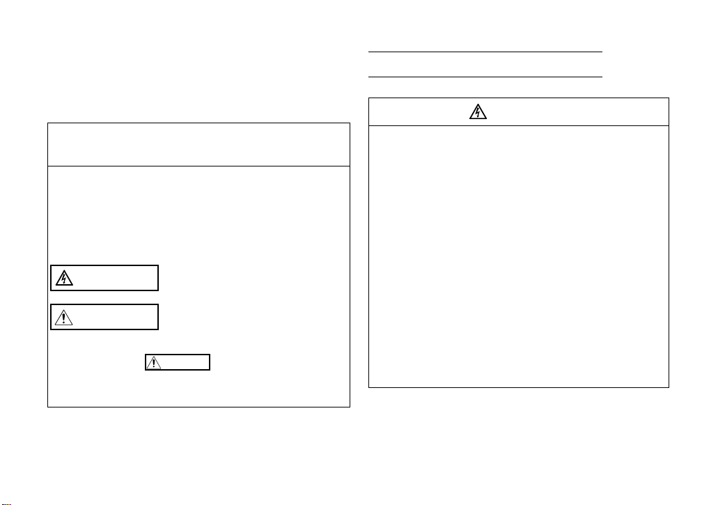
Check the enclosed items.
Plug-in option
.........................................1
O
1
F
2
F
1
2
F
F
O
SD L.RUN
RD L.ERR
RUN
Mounting screw (M3 × 6mm)
.............. 2 (Refer to p age 6.)
700 series.
Hex-head screw fo r o pt ion
mounting (5.5mm)
...............1 (R ef er to page 6.)
5.5mm
1
Communicat i on op tion LED
display cover
.............. 1 (Refer to pa ge 5.)
Terminal block
.........................................1
1
PRE-OPERATION INST RUC TI ON S
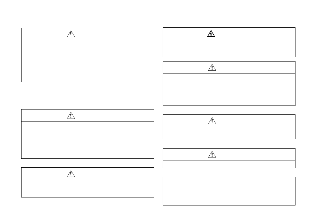
1.1.2 Parts
Connector for
communication
Mount the
accessory
terminal block to
connect to the
network.
(Refer to page 12.)
Mounting
hole
Terminal
layout
DA
DB
DG
SLD
FG
REMARKS
Set the station number using Pr. 542 Communication station number (CC-Link).
Set transmission baud rate using Pr.543 Baud rate selection.
O
1
F
SW2
2
F
SW3
1
2
F
O
Terminating resistor selection switch
Select the resistor value of the terminating resistor.
Front view Rear view
SW1
O
1
F
SW2
2
F
SW3
1
2
F
F
O
Switch for maker
Do not change.
Operation status indication LED......Lit/flicker of the LED indicate operation status.
Lit when refresh data is properly received. Turns off when a data transmission is
L.RUN
SW1
stopped for a certain period of time.
Lit when a communication error occurs in the own station and flickers when settings
L.ERR
of switch, etc. are changed while power is on.
Flickers when the Pr. 542 or Pr. 543 setting is changed.
Turn the power on again or turn the RES signal on.
Lit during normal operation (5V is supplied in the board) (Lit even in the
RUN
noncommunication status.)
Flickers when the master station is Ver.1 and the FR-A7NC is Ver.2 compatible.
(Refer to page 4.)
F
Turns off when no data is transmitted.
SD
Lit when receive data is carrier detected.
RD
SD
RD
L.RUN
L.ERR
RUN
Mounting
hole
Connector
Connect to the inverter option connector.
(Refer to page 32.)
(Refer to page 8.)
Mounting hole
(Refer to page 31, 32.)
(Refer to page 31.)
2

PRE-OPERATION INSTRUCTIONS
1.2 Inverter Option Specifications
Type Inverter plug-in optio n type terminal block connectab le
Power supply 5VDC supplied from th e inverter
Number of units
connected
Cable size
Station type Remote device station
Number of stations
occupied
Communication cable CC-Link dedicated cable, CC-Link Ver. 1.10 compatible CC-Link dedicated cable
42 units max. (Refer to page 37 for the number of stations occupied), May be used with other
equipment.
0.75 to 2mm
Ver.1: occupies one station, Ver.2: occupies one station (selectable from among double,
quadruple and octupl e)
2
1
3
PRE-OPERATION INSTRUCTIONS
1.3 CC-Link Version
1.3.1 CC-Link Ver. 1.10
The conventional CC-Link products, whose inter-station cable lengths have equally been change d to 20cm
(7.87 inch) or more to improve the inter-station cable length restriction, are defi ned as CC-Link Ver. 1.10. In
comparison, the conventional products are defined as CC-Link Ver. 1.00.
Refer to the CC-Link Master Module Manual for the maximum overall cable lengths and inter-station cable
lengths of CC-Link Ver. 1.00 and Ver. 1.10.
CC-Link Ver. 1.10 compatibility conditions
1)All modules that comprise a CC-Link system should be compatible with CC-Link Ver. 1.10.
2)All data link cables should be CC-Link Ver. 1.10 compatible, CC-Link dedicated cables.
(CC-Link Ver. 1.10 compatible cables have a logo or Ver. 1.10 indication.)
CAUTION
In a system that uses the CC- Li nk Ver. 1.00 and Ver. 1.10 modules and cables to get her, the maximum overall
cable length and inter-station cable length are as specified for CC-Link Ver. 1.00.
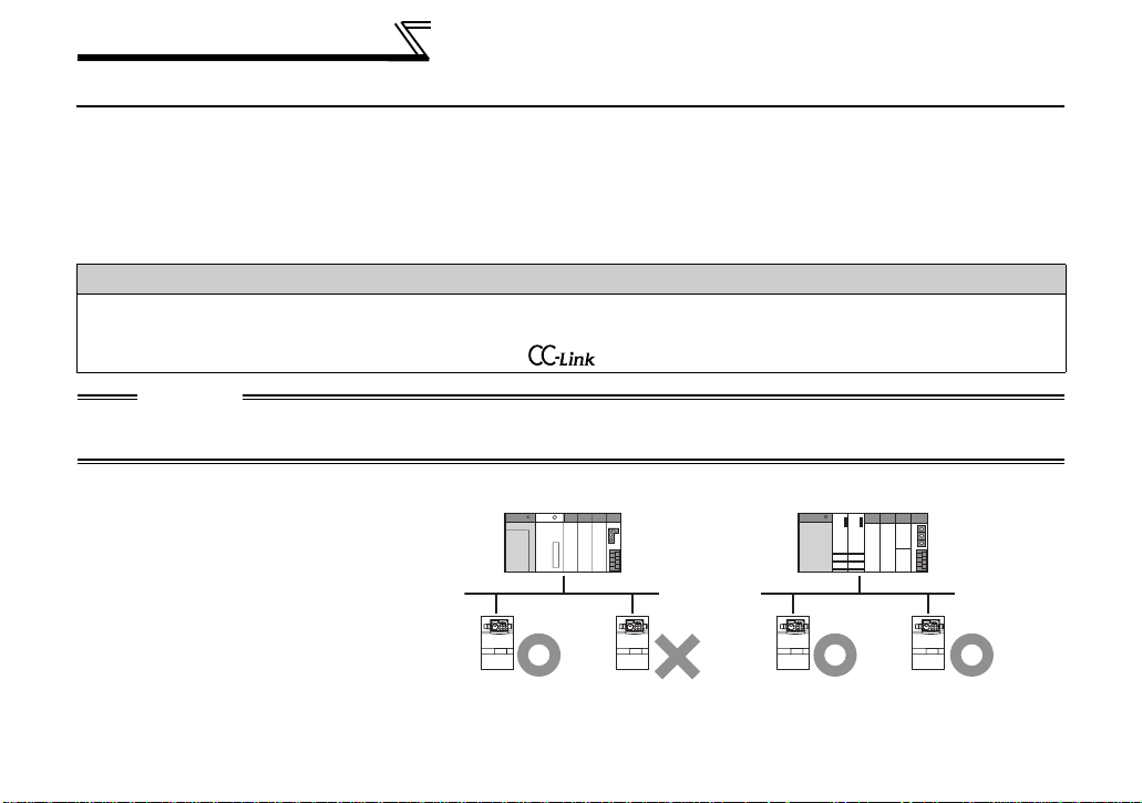
1.3.2 CC-Link Ver. 2
The FR-A7NC is compatible with CCLink Ver.2.
When using the CC-Link Ver.2 setting
with the FR-A7NC, the master station
needs to be compatible with the CCLink Ver.2.
Ver.1
setting
Master station
(Ver.1)
Ver.2
setting
Ver.1
setting
Master station
(Ver.2)
Ver.2
setting
Communication
enabled
Communication
disabled
("RUN" LED flickers)
Communication
enabled
Communication
enabled
4
2 INSTALLATION
2.1 Pre-Installation Instructions
Make sure that the input power of the inverter is off.
CAUTION
With input power on, do not install or remove the plug-in opt ion. Otherwise, the inverter and
plug-in option may be damaged.
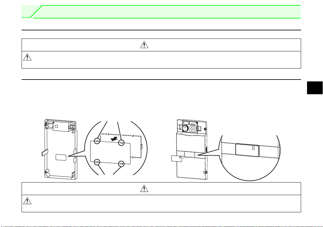
2.2 I ns tallation of the communicati on option LED dis play cover
Mount the cover for displaying the operation status indication LED for the communication option on the
inverter front cover.
2
1)Cut off hooks on the rear of the inverter front
cover with nipper, etc. and open a window for
fitting the LED display cover.
Cut off with a nipper, etc.
2)Fit the communication option LED display
cover to the front of the inverter front cover
and push it into until fixed with hooks.
Fit it so that the position of
lenses is in the upper-right
of the LED display cover.
Fitting drawing
Cut off with a nipper, etc.
CAUTION
Take care not to hurt your hand and such with portions left by cutting h ooks of the rear o f the
front cover.
5
INSTALLATION
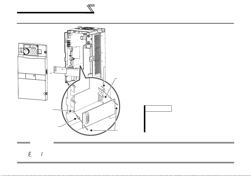
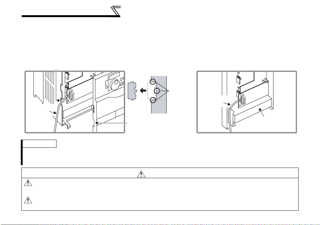
2.3 Installation Procedure
1) Remove the inverter front cov e r.
2) Mount the hex-head screw for option
1)
Screw hole for
option mounting
Inverter side
option
connector
3)
Screw hole for
option mounting
(on earth plate)
Hex-head screw
for option mounting
CAUTION
1. When the inverter can not recognize that the option unit is mount ed due to improper installation, etc.,
" " (option alarm) is displ ayed.
2. Note that a hex-head screw for option mounting or mounting screw may drop duri ng mounting and remova l.
2)
4)
Mounting
screws
mounting into the inverter screw hole (on
earth plate). (size 5.5mm, tightening
torque 0.56N⋅m to 0.75N⋅m)
3) Securely fit the connector of the plug-in
option to the inverter connector along the
guides.
4) Securely fix the both right and left sides
of the plug-in option to the inverter with
the accessory mounting screws. If the
screw holes do not line-up, the connector
may not have been plugged snugly.
Check for loose plugging.
REMARKS
After removing two screws on the right and left
places, remove the plug-in option.
(The plug-in option is easi l y re m oved if the
control circuit terminal block is removed before.)
6
3 WIRING
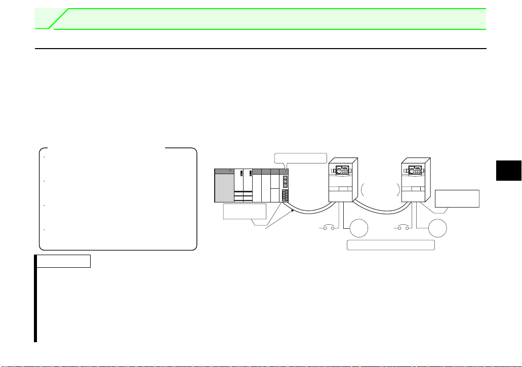
3.1 System Configuration Example
(1) PLC side
Load the "QJ61BT11N", "QJ61BT11", "AJ61QBT11", "A1SJ61QBT11", "AJ61BT11" or "A1SJ61BT11"
"Control & Communication Link system master/local module" on the m ain or extension base unit having
the PLC CPU used as the master station.
(2) Inverter side
Mount the option (FR-A7NC) on the inverter.
(3) Connect the PLC CC-Link unit master station and the terminal block supplied with the FR-A7NC with
the CC-Link dedicated cable. After connecting the terminal block to the FR-A7NC, fit the front cover.
Manual of the CC-Link master station
QJ61BT11N type
CC-Link System Master/Local Module
User's Manual ...SH-080394E
QJ61BT11 type
CC-Link System Master/Local Module
User's Manual ...SH-080016
AJ61QBT11/A1SJ61QBT11 type Control &
Communication Link System Master/Local Module
User's Manual ...IB-66722
AJ61BT11/A1SJ61BT11 type Control &
Communication Link System Master/Local Module
User's Manual ...IB-66721
Terminating
resistor
CC-Link dedicated cable
Master station
QJ61BT11N,
etc.
Power
supply
REMARKS
When the CPU has automatic refresh function (example: QnA series CPU)
⋅
Through communication with the corresponding devices using sequence ladder logic, data is automatically
transferred to the refresh buffer of the master station at the execution of the END instruction to perform
communication wit h th e r emote devices.
⋅ Whe n t he CP U does not have automatic re fresh function (example: AnA ser i es CP U )
Data is transferred to the refresh buffer of the master station directly by sequence ladder logic to perform
communication wit h th e r emote devices.
Inverter
Up to 42
units can be
connected
when only
inverters are
connected
Power
Motor Motor
supply
Remote device station
Inverter
Terminating
resistor
3
7
WIRING
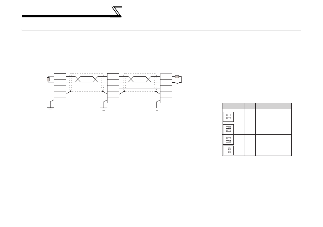
3.2 Connection of Several Inverters
Factory Automation can be applied to several inverters which share a link system as CC-Link remote
device stations and are controlled and monitored by PLC user programs.
*3 Perform setting of the
terminating resistor selection
switch (SW1). (Refer to page 2
for the position of the switch.)
When connecting a ter minating
resistor separately, do not use a
built-in terminating resistor.
(SW2 1-OFF, 2-OFF)
12
O
1
F
OFFOFF
2
F
O
1
F
ON OFF
2
F
O
1
F
OFF ON
2
F
O
1
F
ON ON
2
F
130Ω is a resistance value for the CCLink Ver .1.00 dedicated high performance
cable.
Description
Without
terminating
resistor
Do not use.
130Ω
110 Ω
Terminating
*1
resistor
Master module
DA
DB
DG
Blue
White
Yellow
SLD
FG
Shielded
twisted cable
FR-A7NC*2
DA
DB
DG
SLD
FG
Blue
White
Yellow
Shielded
twisted cable
FR-A7NC
DA
DB
DG
SLD
FG
Terminating
resistor
selection
switch (SW2)
*3
*1 Use the terminating resistors supplied with the PLC.
*2 For the unit in the m i ddle, set 1 and 2 of SW2 to OFF (without terminating
resistor).
For the shield cable of the CC-Link dedicated cable, connect it to
"SLD" of each unit and always earth (ground) it via "FG".
Terminals SLD and FG are connected inside the unit.
8
WIRING
REMARKS
When performing onlin e exchange
The built-in terminating res istor can not be exchanged online since the terminating resistor is on the FR-A7NC board and
disconnected when the terminal block is removed from the FR-A7NC connector for communication. When changing the FRA7NC online, connect a terminating resistor supplied with a PLC master module to the FR-A7NC after modifying it and do
not use the internal terminating resistor (SW2 1-OFF, 2-OFF).
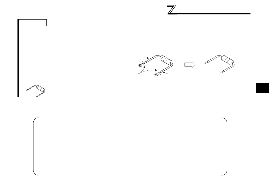
Connection wit h the t erminating resistor
Connect the termin at ing resistor between termin al s
DA-DB of the FR-A7NC at th e end.
Modify the terminating resistors supplied w ith t he
PLC to use.
When a resistor is not su ppl i ed with the master unit,
use a resistor with 110Ω 1/2W available on the market.
Cut
Tube
Cut a tube
(1) Maximum number of units connected to one master station (CC-Link Ver.1.10)
42 units (when connections are inverter only)
If any other units are included, the number of stations occupied depends on the unit
and therefore the following conditions must be satisfied:
{(1 × a) + (2 × b) + (3 × c) + (4 × d)} ≤ 64
a: Number of units occupying 1 station c: Number of units occupying 3 stations
b: Number of units occupying 2 stations d: Number of units occupying 4 stations
{(16 × A) + (54 × B) + (88 × C)} ≤ 2304
A: Number of remote I/O ≤ 64
B: Number of remote device stations ≤ 42
C: Number of local, standby master and intelligent device stations ≤ 26
3
9

WIRING
(2) Maximum number of units connected to one master station (CC-Link Ver.2.00)
42 units (when connections are inverter only)
If any other units are included, the number of stations occupied depends on the unit and
therefore the following conditions must be satisfied:
⋅ {(a + a2 + a4 + a8) + (b + b2 + b4 + b8) × 2 + (c + c2 + c4 + c8) × 3 + (d + d2 + d4 + d8) × 4} ≤ 64
⋅ {(a × 32 + a2 × 32 + a4 × 64 + a8 × 128) + (b × 64 + b2 × 96 + b4 × 192 + b8 × 384) + (c ×
96 + c2 × 160 + c4 × 320 + c8 × 640) + (d × 128 + d2 × 224 + d4 × 448 + d8 × 896)} ≤ 8192
⋅ {(a × 4 + a2 × 8 + a4 × 16 + a8 × 32) + (b × 8 + b2 × 16 + b4 × 32 + b8 × 64) + (c × 12 +
c2 × 24 + c4 × 48 + c8 × 96) + (d × 16 + d2 × 32 + d4 × 64 + d8 × 128)} ≤ 2048
a: Number of single setting devices occupying one station
b: Number of single setting devices occupying two stations
c: Number of single setting devices occupying three stations
d: Number of single setting devices occupying four stations
a2: Number of double setting devices occupying one station
b2: Number of double setting devices occupying two stations
c2: Number of double setting devices occupying three stations
d2: Number of double setting devices occupying four stations
a4: Number of quadruple setting devices occupying one station
b4: Number of quadruple setting devices occupying two stations
c4: Number of quadruple setting devices occupying three stations
d4: Number of quadruple setting devices occupying four stations
a8: Number of octuple setting devices occupying one station
b8: Number of octuple setting devices occupying two stations
c8: Number of octuple setting devices occupying three stations
d8: Number of octuple setting devices occupying four stations
⋅ 16 × A + 54 × B + 88 × C ≤ 2304
A: Numbers of remote I/O ≤ 64
B: Number of remote device stations ≤ 42
C: Number of local and intelligent device stations ≤ 26
10

WIRING
3.3 Connection Cable
In the CC-Link system, use CC-Link dedicated cables.
If the cable used is other than the CC-Link dedicated cable, the performance of the CC-Link system is not
guaranteed.
For the specifications of the CC-Link dedicated cable, refer to the website of the CC-Link Partner
Association.
⋅ Website of the CC-Link Partner Association http://www.cc-link.org/
3
11
WIRING
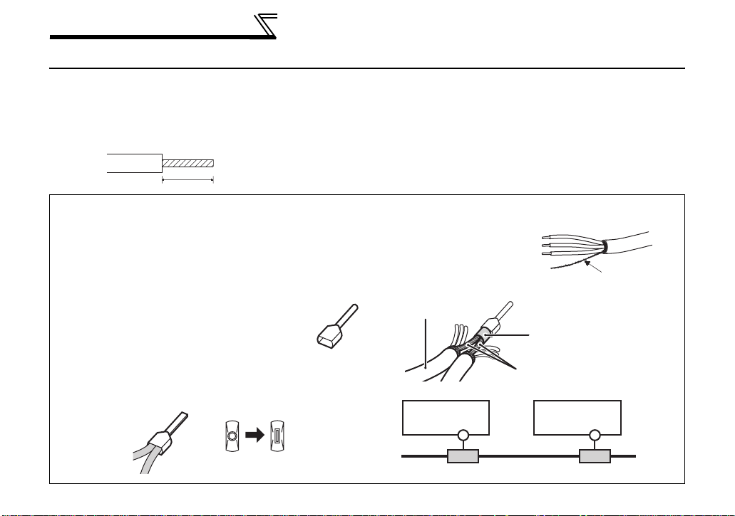
3.4 Wiring
(1) Strip off the sheath of the CC-Link dedicated cable and wind wires to use. If the length of the sheath
pealed is too long, a short circuit may occur among neighboring wires. If the length is too short, wires
might come off.
Use recommended cables. (Refer to page 11.) Recommended tightening torque : 0.22N⋅m to 0.25N⋅m
Cable stripping size
6.5mm
Recommended bar terminal
For wiring of the CC-link communication signal, two CCLink dedicated cabl es need to be twisted to wire to on e
terminal block.
It is recommended to use the followi ng bar terminal an d tool.
Recommended pro ducts (as of October, 2003):
Phoenix Contact Co.,Ltd.
⋅Bar terminal model: AI-TWIN2
⋅Bar terminal cr imping tool: CRI MPFOX UD6,
Note the crimping met h od.
Hold the long side in a long itu di nal di re ct ion and insert it
into the terminal block.
Wire the stripped cable after twisting it to prevent it from
becoming loose. In addition, do not solder it.
Use a bar type terminal as required.
Connection of the shielded cable of the CCLink dedicated cable
Twist the shielded cable and
wire to the terminal SLD.
Use a compression tube and
junction terminal block.
× 0.5-8WH
ZA3
Use of a compression tube
CC-Link dedicated
cable
Use of a junction terminal block
FR-A7NC
SLD
shielded cable
Prevent looseness with
a compression tube
Shielded cable
FR-A7NC
SLD
12
Junction terminal block Junction terminal block
WIRING
(2) Loosen the terminal screw and insert the cable into the terminal.
Screw Size Tightening Torque Cable Size Screwdriver
M2
0.22N
⋅m to 0.25N⋅m
0.3mm
2
to 0.75mm
2
Small flat-blade screwdriver
(Tip thickness: 0.4mm /tip width:
2.5mm)
CAUTION
Undertightening can cause cable disconnection or malfunction. Overtightening can cause a short circuit or
malfunction due to damage to the screw or unit.
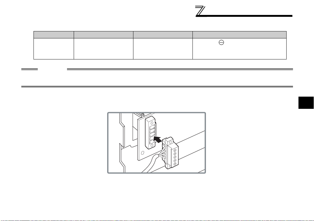
(3) Connect the terminal block to the connector for communication of the communication option.
3
13
WIRING
C
(4) For wiring of the 30K(00620 (EC Version)) or less, route wires between the control circuit terminal block
and front cover. If cables can not be routed between the control circuit terminal block and front cover (5.5K
or less, 37K or more...7.76mm, 7.5K to 30K...7.26mm), remove a hook of the front cover and use a space
become available.
For wiring of the 37K(00770 (EC Version)) or more, use the space on the left side of the control circuit
terminal block.
Wiring can be also performed using a cable
groove in the inverter side surface
Cut off
with a
CC-Link
dedicated
cable
nipper,
etc.
Cut off a hook on the inverter
front cover side surface.
(Cut off so that no portion is left.)
CC-Link
dedicated
cable
Control circuit
terminal block
30K or less 37K or more
REMARKS
⋅ When the hook of the inverter front cover is cut off for wiring, the protective structure (JEM1030) changes to open
type (IP10).
⋅ If the terminal block of the FR - A7NC is removed, built-in terminating resistor can not be used. (Refer to page 8.)
AUTION
When installing the inverter front cover, the cables to the inverter's control circuit terminals and
option terminals should be routed properly in the wiring space to prevent them from being
caught between the inverter and its cover.
After wiring, wire offcuts must not be left in the inverter. They may cause an error, failure or
malfunction.
14

4 INVERTER SETTING
4.1 Parameter List
The following parameters are used for the plug-in option (FR-A7NC).
Set the values according to need.
Parameter
Number
79 Operation mode selection 0 to 4, 6, 7 1 0 17
313
*1 DO0 output selection
314
*1 DO1 output selection
*1 DO2 output selection
315
338 Communication operation command source 0, 1 1 0 21
339 Com m unication speed comm and source 0, 1, 2 1 0 21
340 Com m unication startup mode selection 0, 1, 2, 10, 12 1 0 17
342 Communication EEPROM write selection 0, 1 1 0 23
*1 Communication reset selection 0, 1 1 0 30
349
*1
500
501 *1
502
542
543 *1, 2, 3 Baud rate selection (CC-Link) 0 to 4 1 0 32
544
550
*1 Parameters which can be displayed when the plug-in option (FR-A7NC) is mounted.
*2 The setting is reflecte d after inver t er res et or at th e next power-on.
*3 "L.ERR" of the LED flickers if the setting is changed. If the inverter is reset, the setting is reflected and LED turns off.
*4 The setting values " 7, 107" can be set only for the 75K(01800-EC, S75K-CH) or more.
Communication error recognition waiting time
Communication error occurrence count display
*1
Communication error time stop mo de s elect io n
*1, 2, 3 Com m unication station number (CC-Link) 1 to 64 1 1 31
*1, 2 CC-Link extended setting 0, 1, 12, 14, 18 1 0 37
*2 NET mode control sour ce sel ection 0, 1, 9999 1 9999 20
The setting value of "70 to 78" can be set only for EC and CH ver si ons.
Name Setting Range
0 to 5, 7, 8, 10 to 19, 25, 26, 45 to 47, 64,
70 to 78, 86 to 96, 98, 99, 100 to 105, 107,
108, 110 to 1 16, 125, 126, 145 to 147,
164, 170, 186 to 196, 198, 199, 9999
0 to 999.8s 0.1s 0 24
01025
0 to 3 1 0 26
Minimum
Setting
Increments
1999947
*4
Initial
Value
Refer
to
Page
4
15

INVERTER SETTING
4.2 Operation Mode Setting
The inverter mounted with a communication option has three operation modes.
(1) PU operation [PU].............. Controls the inverter from the key of the operation panel (FR-DU07)
mounted on the inverter.
(2) External operation [EXT] ...Controls the inverter by switching on/off external signals connected to the
control circuit terminals of the inverter.
(The inverter is factory-set to this mode.)
(3) Network operation [NET]...Controls the inverter with instructions from the network via the
communication option.
(The operation signal and running frequency can be entered from the
control circuit terminals depending on the Pr. 338 Communication operation
command source and Pr. 339 Communication speed command source setting.
Refer to page 21.)
4.2.1 Operation mode indication
FR-DU07
Operation mode indication
(The inverter operates according to the LED lit mode.)
PU: PU operation mode
EXT: External operation mode
NET: Network operation mode
16

INVERTER SETTING
4.2.2
(1) Operation mode switching conditions
Before switching the operation mode, check that:
1) The inverter is at a stop;
2) Both the STF and STR signals are off; and
3) The Pr. 79 Operation mode selection setting is correct.
(Set with the operation panel of the inverter.)
Refer to the inverter manual (applied) for details of Pr. 79.
(2) Operation mode selection at power on and at re stora tion f rom instantaneous power failure
The operation mode at power on and at restoration from instantaneous power failure can be selected.
Set a value other than "0" in Pr. 340 to select the network operation mode.
After started in network operation mode, parameter write from the network is enabled. (Refer to page 6 9 for
a program example for parameter write.)
REMARKS
1. Change of the Pr. 340 setting is made valid when powering on or resetting the inverter.
2. Pr. 340 can be changed with the operation panel independent l y of the operation mode.
Operation mode switching and communication startup mode (Pr. 79, Pr. 340)
4
17

INVERTER SETTING
Pr. 340
Setting
(initial
value)
1, 2 *2
10, 12
*1 Operation mode can not be directly changed between the PU operation mode and network operation mode.
*2 The Pr. 340 settings "2, 12" are mainly used for communication operation using the inverter RS-485 terminal.
Pr. 79
Setting
0 (initial
value)
0
3, 4 External/PU combined operation mode Operation mode switching is disallowed
3, 4 External/PU combined operation mode
*2
3, 4 External/PU combined operat ion mode Same as when Pr. 340 = "0"
When a value other than "9999 " (Selection of aut omatic restart after insta ntaneous power fa ilure) is set in Pr. 57 Restart coasting time, the
inverter will resume the same operation state which was in before after power has been restored from an instantaneous power failure.
Operation Mode at Power on or Power
External operation mode
1 PU operation mode PU operation mode fixed
2 External operation mode
6 External operation mode
X12 (MRS) signal ON.....external operation mode Switching among the external, PU, and NET operation mode i s enabled
7
X12 (MRS) signal OFF... external operation mode
0 NET operation mode
1 PU operation mode
2 NET operation mode
6 NET operation mode
X12 (MRS) signal ON.... NET operation mode
7
X12 (MRS) signal OFF... external operation mode
0 NET operation mode Switching bet w ee n the P U and NET o pe rat io n mo de is en abl ed *3
1 PU operation mode Same as when Pr. 340 = "0"
2 NET operation mode NET operation mode fixed
6 NET operation mode
7 External operation mode Same as when Pr. 340 = "0"
Restoration
Switching among the external, PU, and NET operation mode is
enabled *1
Switching between the external and Net operation mode is enabled
Switching to the PU operation mode is disallowed
Switching among the external, PU, and NET operation mode is enabled
while running.
External operation mode fixed (Forc i bly switc hed to externa l
operation mode.)
Same as when Pr. 340 = "0"
Switching between the PU and NET operation mode is enabled while running
Operation Mode Switchover
*3 Op erat ion mo de can be change d bet ween th e PU oper ati on mod e and netw ork operati on mode with of the operation p anel (FR-
DU07) and X65 signal.
*1
*3
18
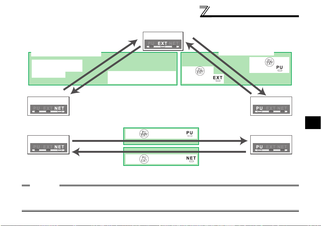
(3) Operation mode switching method
INVERTER SETTING
When "0, 1, or 2" is set in Pr. 340
Switching from the network
Switch to the external
operation mode from
the network.
Network operation PU operation
Switch to the network operation
mode from the network.
When "10 or 12" is set in Pr. 340
Network operation PU operation
For the switching method from the external terminal, refer to the inverter manual (applied).
Refer to page 55 for a switching method from the network.
External operation
Press of
the PU to light .
Press of of the PU to light .
Press of of the PU to light .
Switching from the PU
Press of the
PU to light .
CAUTION
⋅ When starting the inverter in network operation mode at powering on or an inverter reset, set a value other than 0 in
Pr. 340. (Refer to page 17)
⋅ When setting a value other th an 0 in Pr. 340, make sure that the initial settings of the inverter are correct.
4
19

INVERTER SETTING
4.3 Operation and Speed Command Source (Pr. 338 , Pr. 339, Pr. 55 0)
(1) Select control source for the network operation mode (Pr. 550)
A control location for the network operation mode can be selected from either the inverter RS-485
terminal or communication option.
When using a communication option, set "0 or 9999 (initial value)" in Pr. 550.
Parameter
Number
550
NET mode operation
command source s el ect i on
Name Initial Value
Refer to the inverter manual (applied) for details.
9999
Setting
Range
0
1
9999
Description
Control source for the communication
option is valid
(control source of the inverter RS-485
terminal is invalid)
Control source of the inverter RS-485
terminal is valid
(control source for the
communication option is invalid)
Automatic recognition of the
communication option
Normally, control source of the RS485 terminal is valid. W hen a
communication opt io n i s m ounted,
the control source of the
communication option is valid.
20
INVERTER SETTING
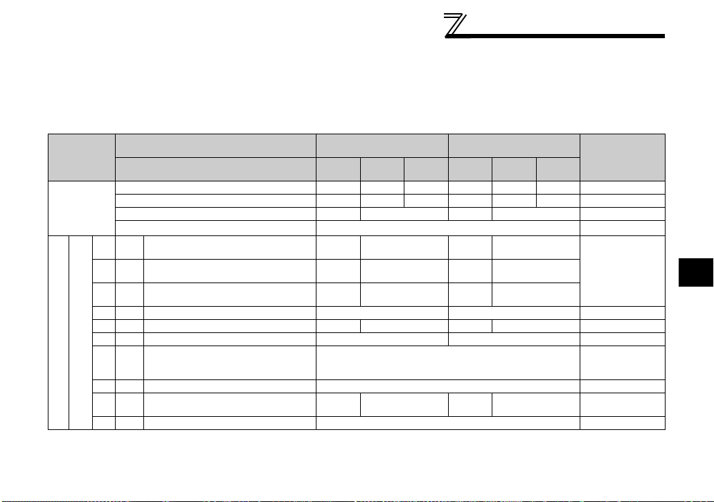
(2) Selection of control source for the network operation mode (Pr. 338, Pr. 339)
⋅ As control sources, there are operation command source that controls signals related to the inverter
start command and function selection and speed command source that controls signals related to
frequency setting.
⋅ In network operation mode, commands from the external terminals and communication are as listed
below.
Control
Location
Selection
Fixed
functions
(Functions
equivalent
to terminals)
Selective functions
Pr. 178 to Pr. 189 settings
10 X10 Inverter operation enable signal External
Pr. 338 Communication operation
command source
Pr. 339 Communication speed
Running frequency from communication NET NET NET NET
Terminal 2 External External
Terminal 4 External External
Terminal 1 Compensation
0RL
1RM
2RH
3 RT Second function selection NET External
4 AU Terminal 4 input selection Combined Combined
5 JOG Jog operation selection External
6CS
7 OH External thermal relay input External
8 REX 15-speed selection NET External NET External
command source
Low-speed operation command/
remote setting clear
Middle-speed operation command/
remote setting deceleration
High-speed operation command/
remote setting acceleration
Automatic restart after
instantaneous power failure
selection
0:NET
0:NET 1:External
1:
External2:External
NET External NET External
NET External NET External
NET External NET External
0:NET
External
1:
External2:External
Pr. 59 = "0"
(multi-speed)
Pr. 59 = "1, 2"
Pr. 59 = "0"
(multi-speed)
Remarks
(remote)
4
21
 Loading...