

Mitsubishi Electric FR-A7AZ, FR-A720-75K, FR-A720-55K, FR-A740-75K, FR-A740-55K Instruction Manual

INVERTER
Plug-in option
FR-A7AZ
INSTRUCTION MANUAL
Bipolar analog output function
High resolution analog input function
Motor thermistor interface
PRE-OPERATION INSTRUCTIONS
1
INSTALLATION AND WIRING
2
PARAMETER LIST
3
BIPOLAR ANALOG OUTPUT
4
HIGH RESOLUTION ANALOG INPUT
5
MOTOR THERMISTOR INTERFACE
6
Thank you for choosing this Mitsubishi Inverter plug-in option.
This Instruction Manual gives handling information and
precautions for use of this equipment. Incorrect handling might
cause an unexpected fault. Before using the equipment, please
read this manual carefully to use the equipment to its optimum.
Please forward this manual to the end user.
This section is specifically about
safety matters
Do not attempt to install, operate, maintain or inspect this
product until you have read through this Instruction Manual and
appended documents carefully and can use the equipment
correctly. Do not use this product until you have a full
knowledge of the equipment, safety information and
instructions.
In this Instruction Manual, the safety instruction levels are
classified into "WARNING" and "CAUTION".
Incorrect handling may cause
WARNING
CAUTION
The level may even lead to a serious
consequence according to conditions. Both instruction levels
must be followed because these are important to personal
safety.
CAUTION
hazardous conditions, resulting in
death or severe injury.
Incorrect handling may cause
hazardous conditions, resulting in
medium or slight injury, or may cause
only material damage.
SAFETY INSTRUCTIONS
1. Electric Shock Prevention
WARNING
• While power is ON or when the inverter is running, do not
open the front cover. You may get an electric shock.
• Do not run the inverter with the front cover or wiring cover
removed. Otherwise, you may access the exposed highvoltage terminals and charging part and get an electric shock.
• Even if power is OFF, do not remove the front cover except for
wiring or periodic inspection. You may accidentally touch the
charged inverter circuits and get an electric shock.
• Before wiring or inspection, power must be switched OFF. To
confirm that, LED indication of the operation panel must be
checked. (It must be OFF.) Any person who is involved in
wiring or inspection shall wait for at least 10 minutes after the
power supply has been switched OFF and check that there
are no residual voltage using a tester or the like. The
capacitor is charged with high voltage for some time after
power OFF, and it is dangerous.
• Any person who is involved in wiring or inspection of this
equipment shall be fully competent to do the work.
• The plug-in option must be installed before wiring. Otherwise,
you may get an electric shock or be injured.
• Do not touch the plug-in option or handle the cables with wet
hands. Otherwise you may get an electric shock.
• Do not subject the cables to scratches, excessive stress,
heavy loads or pinching. Otherwise you may get an electric
shock.
A-1
2. Injury Prevention
3) Usage
CAUTION
• The voltage applied to each terminal must be the ones
specified in the Instruction Manual. Otherwise burst, damage,
etc. may occur.
• The cables must be connected to the correct terminals.
Otherwise burst, damage, etc. may occur.
• Polarity must be correct. Otherwise burst, damage, etc. may
occur.
• While power is ON or for some time after power-OFF, do not
touch the inverter as they will be extremely hot. Doing so can
cause burns.
3. Additional Instructions
Also the following points must be noted to prevent an accidental
failure, injury, electric shock, etc.
1) Transportation and mounting
CAUTION
• Do not install or operate the plug-in option if it is damaged or
has parts missing.
• Do not stand or rest heavy objects on the product.
• The mounting orientation must be correct.
• Foreign conductive objects must be prevented from entering
the inverter. That includes screws and metal fragments or
other flammable substances such as oil.
2) Trial run
CAUTION
• Before starting operation, each parameter must be confirmed
and adjusted. A failure to do so may cause some machines to
make unexpected motions.
WARNING
• Do not modify the equipment.
• Do not perform parts removal which is not instructed in this
manual. Doing so may lead to fault or damage of the inverter.
CAUTION
•
When parameter clear or all parameter clear is performed, the
required parameters must be set again before starting operations
because all parameters return to the initial value.
• Static electricity in your body must be discharged before you
touch the product. Otherwise the product may be damaged.
4) Maintenance, inspection and parts replacement
CAUTION
• Do not test the equipment with a megger (measure insulation
resistance).
5) Disposal
CAUTION
• This inverter plug-in option must be treated as industrial
waste.
6) General instruction
Many of the diagrams and drawings in this Instruction Manual
show the inverter without a cover or partially open for
explanation. Never operate the inverter in this manner. The
cover must be reinstalled and the instructions in the inverter
manual must be followed when operating the inverter.
A-2

⎯ CONTENTS ⎯
1 PRE-OPERATION INSTRUCTIONS 1
1.1 Inverter model ....................................................................................................................................1
1.2 Unpacking and product confirmation ..............................................................................................2
1.2.1 Product confirmation.......................................................................................................................................2
1.2.2 Parts ...............................................................................................................................................................3
1.3 Compatible inverters .........................................................................................................................4
2 INSTALLATION AND WIRING 7
2.1 Pre-installation instructions .............................................................................................................7
2.2 Installation procedure .......................................................................................................................8
2.3 Wiring................................................................................................................................................10
3 PARAMETER LIST 14
4 BIPOLAR ANALOG OUTPUT 16
4.1 Connection diagram ........................................................................................................................16
4.2 Terminals ..........................................................................................................................................17
4.3 Bipolar analog outputting parameter.............................................................................................17
4.3.1 Parameter list ...............................................................................................................................................17
I

4.3.2 Calibration of the indicator (Pr. 838, Pr. 857, C0).........................................................................................18
4.3.3 Monitor item list ............................................................................................................................................19
4.3.4 Terminal DA1 response level adjustment (Pr. 839)......................................................................................20
5 HIGH RESOLUTION ANALOG INPUT 21
5.1 Connection diagram ........................................................................................................................21
5.2 Terminals ..........................................................................................................................................21
5.3 High resolution analog input parameter........................................................................................22
5.3.1 Parameter list ...............................................................................................................................................22
5.3.2 Selection of terminal 6 function (Pr. 406) .....................................................................................................23
5.3.3 Calibration of terminal 6 (Pr. 148, Pr. 149, Pr. 846 to Pr. 848, C30 to C37).................................................25
5.4 Noise reduction techniques............................................................................................................28
5.5 Specifications...................................................................................................................................29
6 MOTOR THERMISTOR INTERFACE 30
6.1 Connection diagram ........................................................................................................................30
6.2 Terminals ..........................................................................................................................................31
6.3 Motor thermistor parameter............................................................................................................31
6.3.1 Parameter list ...............................................................................................................................................31
6.3.2 Thermistor setting.........................................................................................................................................32
6.3.3 Activating the motor thermistor.....................................................................................................................33
6.3.4 Thermistor calibration (C29)......................................................................................................................... 34
6.3.5 Motor temperature detection signal..............................................................................................................37
6.3.6 Motor temperature monitor output................................................................................................................38
II
1 PRE-OPERATION INSTRUCTIONS
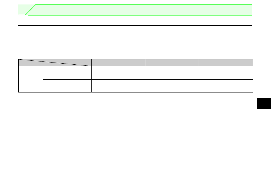
1.1 Inverter model
The inverter models 55K and 75K stated in this Instruction Manual differ according to -NA, -EC, -CH(T)
versions. Refer to the following correspondence table for each inverter type. (Refer to the Instruction Manual
of each inverter for the inverter type.)
For example, "for the 75K or higher" indicates "for the FR-A740-01440-NA or higher" in the case of FRA740 of NA version.
NA EC CH
FR-A720-55K FR-A720-02150-NA ⎯⎯
A700
FR-A720-75K FR-A720-02880-NA ⎯⎯
FR-A740-55K FR-A740-01100-NA FR-A740-01800-EC FR-A740-55K-CHT
FR-A740-75K FR-A740-01440-NA FR-A740-02160-EC FR-A740-75K-CHT
1
1
PRE-OPERATION INSTRUCTIONS
1.2 Unpacking and product confirmation
Take the plug-in option out of the package, check the product name, and confirm that the product is as you
ordered and intact.
This product is a plug-in option dedicated for the FR-A
700/A701 series.
Refer to page 4 for details of compatible inverters.
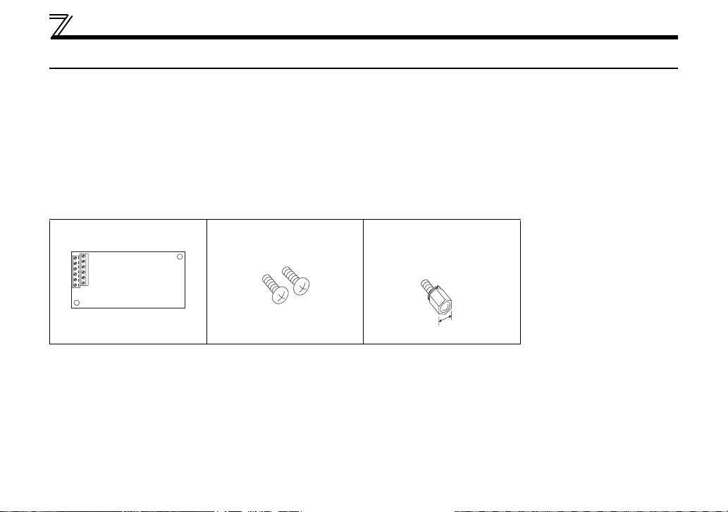
1.2.1 Product confirmation
Check the enclosed items.
Plug-in option ...................1 Mounting screw (M3 × 6mm)
.............. 2 (Refer to page 8.)
Hex-head screw for option
mounting (5.5mm)
...............1 (Refer to page 8.)
5.5mm
2
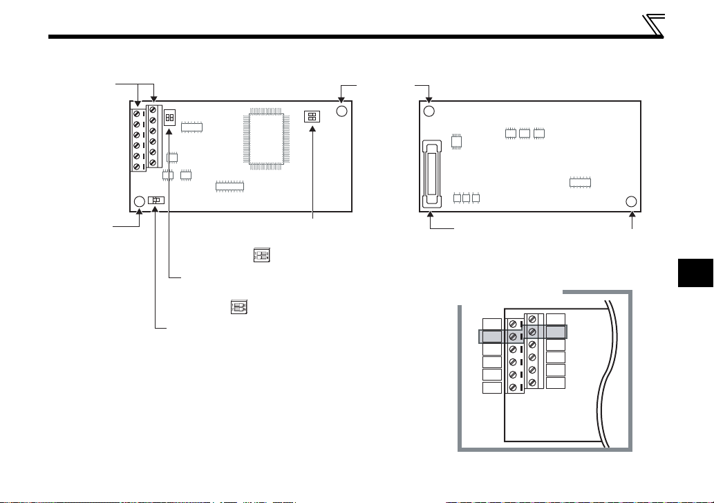
1.2.2 Parts
Terminal
block
PRE-OPERATION INSTRUCTIONS
Front view Rear view
SW1
N
O
1
2
2
N
1
O
Mounting
hole
SW3
Mounting
hole
SW2
FR-A7AZ
Switch for manufacturer setting (SW3)
Do not change from initially-set status
(1, 2: OFF ).
Switch for manufacturer setting (SW1)
Do not change from initially-set status
(1, 2: ON ).
O
1
N
2
Switch for thermistor calibration (SW2)
Change the setting when calibrating the
thermistor.
(Refer to page 34.)
*
1 All terminal 5 are connected internally.
*
2 TST are not used. Keep these open.
Accidental connection will damage the
option.
Connector
Connect to the inverter
option connector.
(Refer to page 8.)
Terminal layout
*1
5
TST
*2
5
*1
*1
5
*1
5
TH2
6
TST
DA1
5
5
TH1
Mounting
hole
1
*2
*1
*1
3

PRE-OPERATION INSTRUCTIONS
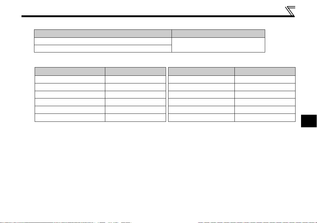
1.3 Compatible inverters
This product can be used with the FR-A700 series inverters assembled in and after July 2006 and the FRA701 series.
Check the SERIAL number indicated on the inverter rating plate or package.
Refer to the Inverter Manual for the location of the rating plate.
Rating plate example
Symbol Year Month Control number
The SERIAL consists of one symbol, two characters indicating production year
and month, and six characters indicating control number.
The last digit of the production year is indicated as the Year, and the Month is
indicated by 1 to 9, X (October), Y (November), or Z (December.)
6 7 {{{{{{
SERIAL (Serial No.)
4
PRE-OPERATION INSTRUCTIONS
(1) Japanese specification/NA specification
Type SERIAL (the first three digits)
FR-A720-0.4K to 90K, FR-A740-0.4K to 500K
FR-A720-00030 to 03460-NA, FR-A740-00015 to 09620-NA
{{{{{{ or later
67
(2) CHT specification
Typ e SERIAL Type SERIAL
FR-A740-0.4K/0.75K-CHT M67{{{{{{ or later
FR-A740-1.5K to 3.7K-CHT N67{{{{{{ or later FR-A740-280K-CHT G67{{{{{{ or later
FR-A740-5.5K/7.5K-CHT M67{{{{{{ or later FR-A740-315K-CHT F67{{{{{{ or later
FR-A740-11K to 22K-CHT N67{{{{{{ or later FR-A740-355K-CHT D67{{{{{{ or later
FR-A740-30K to 55K-CHT K67{{{{{{ or later FR-A740-400K/450K-CHT F67{{{{{{ or later
FR-A740-75K to 160K-CHT G67{{{{{{ or later FR-A740-500K-CHT G67{{{{{{ or later
FR-A740-185K to 250K-CHT
F67{{{{{{ or later
1
5
PRE-OPERATION INSTRUCTIONS
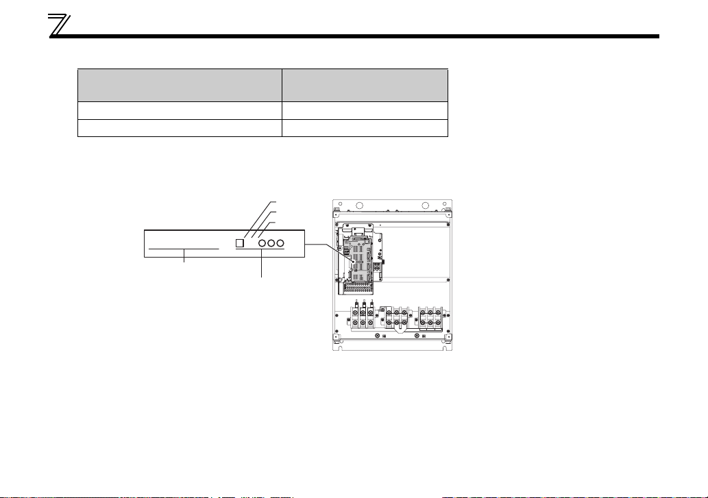
(3) EC specification
Type
SERIAL
(the first three digits)
FR-A740-00023 to 00620-EC E67 or later
FR-A740-00770 to 12120-EC* D67 or later
* For the FR-A740-00770 to 12120-EC
Check the SERIAL indicated on the serial number sticker shown below.
Serial number sticker example
FR-CA70-EC 67
SERIAL
Control unit type
The SERIAL consists of one symbol, two characters
indicating production year and month, and three
characters indicating control number.
The last digit of the production year is indicated as the
Year, and the Month is indicated by 1 to 9, X (October),
Y (November), or Z (December.)
SERIAL
Symbol
Yea r
Month
VUW
• To check the SERIAL, the front cover must be removed.
For the removal of the front cover, refer to the Inverter Manual.
6
2 INSTALLATION AND WIRING
2.1 Pre-installation instructions
Make sure that the input power of the inverter is off.
CAUTION
With input power on, do not install or remove the plug-in option. Otherwise, the inverter and
plug-in option may be damaged.
Static electricity in your body must be discharged before you touch the product. Otherwise the
product may be damaged.
2
7
INSTALLATION AND WIRING
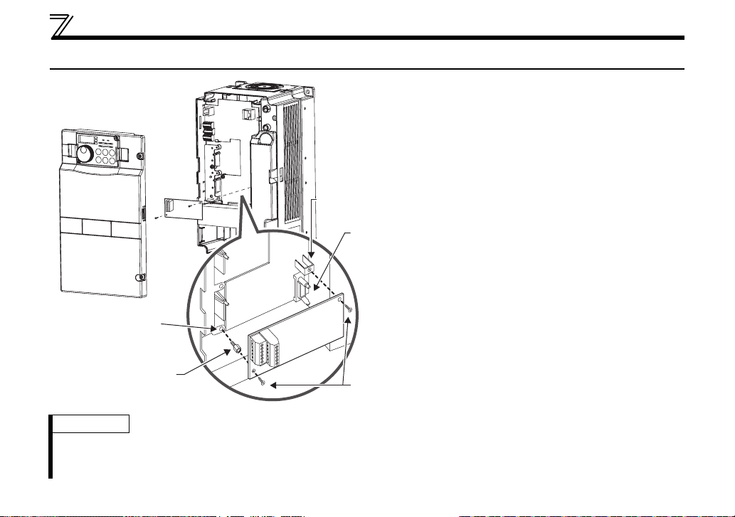
2.2 Installation procedure
1) Remove the inverter front cover.
1)
Screw hole for
option mounting
Inverter side
option
connector
3)
Screw hole for
option mounting
(on earth plate)
Hex-head screw
for option mounting
REMARKS
⋅ After removing two screws on the right and left places, remove the plug-in option.
(When the plug-in option is mounted in the connector 3, it is easier to remove the plug-in option after removing a
control circuit terminal block.)
2)
4) Mounting
screws
2) Mount the hex-head screw for option
mounting into the inverter screw hole
(on earth plate). (Size 5.5mm,
tightening torque 0.56N⋅m to 0.75N⋅m)
3) Securely fit the connector of the plug-in
option to the inverter connector along
the guides.
4) Securely fix the both right and left sides
of the plug-in option to the inverter with
the accessory mounting screws.
(Tightening torque 0.33N⋅m to 0.40N⋅m)
If the screw holes do not line-up, the
connector may not have been plugged
securely. Check for loose plugging.
8
INSTALLATION AND WIRING
CAUTION
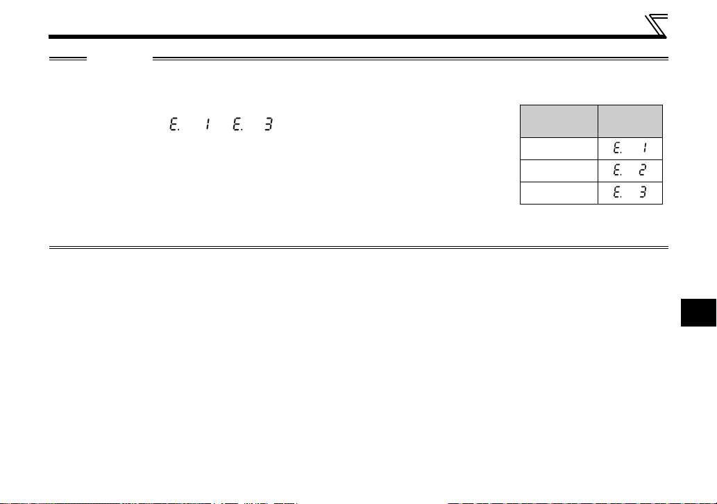
• Only one type of option per inverter may be used. When two or more options are mounted, priority is in
order of inverter option connectors 1, 2 and 3, the options having lower priority are inoperative.
• When the inverter cannot recognize that the option is mounted due to improper
installation, etc., " to " (option alarm) are displayed. The errors
shown differ according to the mounting positions (connectors 1, 2, 3).
• Take care not to drop a hex-head screw for option mounting or mounting screw during mounting and removal.
• Pull out the option straight to remove. Otherwise, the connector may be damaged.
Mounting
Position
Connector 1
Connector 2
Connector 3
Error
Display
2
9
 Loading...