

Mitsubishi Electric FR-A7AX E kit-SC Instruction Manual

INVERTER
Plug-in option
FR-A7AX E kit-SC
INSTRUCTION MANUAL
16-bit digital input function
PRE-OPERATION INSTRUCTIONS
INSTALLATION AND WIRING
CONNECTION DIAGRAM AND TERMINAL
PARAMETERS
1
2
3
4
Thank you for choosing this Mitsubishi Inverter plug-in option.
This Instruction Manual gives handling information and
precautions for use of this equipment. Incorrect handling might
cause an unexpected fault. Before using the equipment, please
read this manual carefully to use the equipment to its optimum.
Please forward this manual to the end user.
This section is specifically about
safety matters
Do not attempt to install, operate, maintain or inspect this
product until you have read through this Instruction Manual and
appended documents carefully and can use the equipment
correctly. Do not use this product until you have a full
knowledge of the equipment, safety information and
instructions.
In this Instruction Manual, the safety instruction levels are
classified into "WARNING" and "CAUTION".
Incorrect handling may cause
WARNING
CAUTION
The level may even lead to a serious
consequence according to conditions. Both instruction levels
must be followed because these are important to personal
safety.
CAUTION
hazardous conditions, resulting in
death or severe injury.
Incorrect handling may cause
hazardous conditions, resulting in
medium or slight injury, or may cause
only material damage.
SAFETY INSTRUCTIONS
1. Electric Shock Prevention
WARNING
• While power is ON or when the inverter is running, do not
open the front cover. You may get an electric shock.
• Do not run the inverter with the front cover or wiring cover
removed. Otherwise, you may access the exposed highvoltage terminals and charging part and get an electric shock.
• Even if power is OFF, do not remove the front cover except for
wiring or periodic inspection. You may accidentally touch the
charged inverter circuits and get an electric shock.
• Before wiring or inspection, power must be switched OFF. To
confirm that, LED indication of the operation panel must be
checked. (It must be OFF.) Any person who is involved in
wiring or inspection shall wait for at least 10 minutes after the
power supply has been switched OFF and check that there
are no residual voltage using a tester or the like. The
capacitor is charged with high voltage for some time after
power OFF, and it is dangerous.
• Any person who is involved in wiring or inspection of this
equipment shall be fully competent to do the work.
• The plug-in option must be installed before wiring. Otherwise,
you may get an electric shock or be injured.
• Do not touch the plug-in option or handle the cables with wet
hands. Otherwise you may get an electric shock.
• Do not subject the cables to scratches, excessive stress,
heavy loads or pinching. Otherwise you may get an electric
shock.
A-1
2. Injury Prevention
3) Usage
CAUTION
• The voltage applied to each terminal must be the ones
specified in the Instruction Manual. Otherwise burst, damage,
etc. may occur.
• The cables must be connected to the correct terminals.
Otherwise burst, damage, etc. may occur.
• Polarity must be correct. Otherwise burst, damage, etc. may
occur.
• While power is ON or for some time after power-OFF, do not
touch the inverter as they will be extremely hot. Doing so can
cause burns.
3. Additional Instructions
Also the following points must be noted to prevent an accidental
failure, injury, electric shock, etc.
1) Transportation and mounting
CAUTION
• Do not install or operate the plug-in option if it is damaged or
has parts missing.
• Do not stand or rest heavy objects on the product.
• The mounting orientation must be correct.
• Foreign conductive objects must be prevented from entering
the inverter. That includes screws and metal fragments or
other flammable substances such as oil.
2) Trial run
CAUTION
• Before starting operation, each parameter must be confirmed
and adjusted. A failure to do so may cause some machines to
make unexpected motions.
WARNING
• Do not modify the equipment.
• Do not perform parts removal which is not instructed in this
manual. Doing so may lead to fault or damage of the inverter.
CAUTION
•
When parameter clear or all parameter clear is performed, the
required parameters must be set again before starting operations
because all parameters return to the initial value.
• For prevention of damage due to static electricity, nearby
metal must be touched before touching this product to
eliminate static electricity from your body.
4) Maintenance, inspection and parts replacement
CAUTION
• Do not test the equipment with a megger (measure insulation
resistance).
5) Disposal
CAUTION
• This inverter plug-in option must be treated as industrial
waste.
6) General instruction
Many of the diagrams and drawings in this Instruction Manual
show the inverter without a cover or partially open for
explanation. Never operate the inverter in this manner. The
cover must be reinstalled and the instructions in the inverter
manual must be followed when operating the inverter.
A-2

— CONTENTS —
1 PRE-OPERATION INSTRUCTIONS 1
1.1 Unpacking and Product Confirmation .............................................................................................1
1.1.1 Product confirmation.......................................................................................................................................1
1.2 Parts ....................................................................................................................................................2
1.3 Specifications.....................................................................................................................................3
2 INSTALLATION AND WIRING 4
2.1 Pre-Installation Instructions .............................................................................................................4
2.2 Installation Procedure .......................................................................................................................4
2.3 Wiring..................................................................................................................................................9
3 CONNECTION DIAGRAM AND TERMINAL 12
3.1 Connection Diagram........................................................................................................................12
3.2 Internal Block Diagram ....................................................................................................................14
3.3 Terminals ..........................................................................................................................................15
3.4 Code Input Example ........................................................................................................................16
4 PARAMETERS 17
4.1 Parameter List ..................................................................................................................................17
4.2 Parameter Setting ............................................................................................................................18
4.2.1 Selection of input method (Pr. 304).............................................................................................................. 18
4.2.2 Read timing operation selection (Pr. 305) ....................................................................................................19
4.2.3 Bias and gain adjustment (Pr. 300, Pr. 301, Pr. 302, Pr. 303) .....................................................................21
4.2.4 Digital input unit selection (Pr. 329)..............................................................................................................24
4.3 Instructions ......................................................................................................................................25
I
1 PRE-OPERATION INSTRUCTIONS
1.1 Unpacking and Product Confirmation
Take the plug-in option out of the package, check the product name, and confirm that the product is as you
ordered and intact.
This product is a plug-in option for the FR-E700-SC series
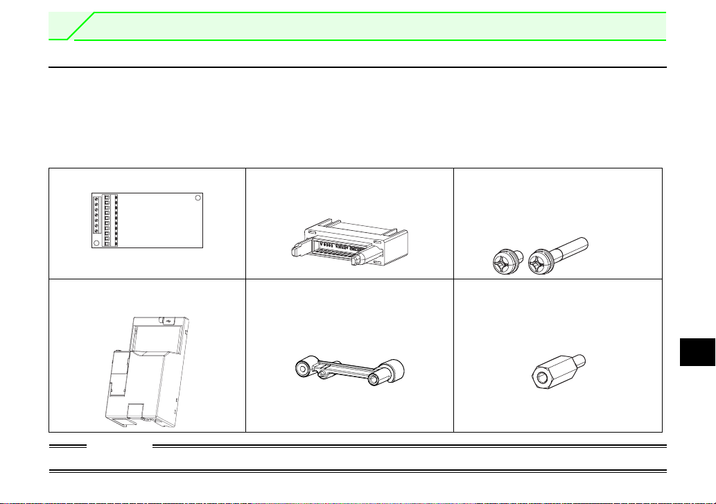
1.1.1 Product confirmation
Check the enclosed items.
Plug-in option ................................1 Junction connector .............................1
(Refer to page 5, 7.)
(safety stop function model).
M3 mounting screw
(Long) (M3 × 20mm) .........................1
(Short) (M3 × 6mm) ...........................1
(Refer to page 5, 7.)
Front cover for plug-in option......... 1
(Refer to page 5, 7)
CAUTION
• Install a provided front cover for plug-in option, in place of the inverter front cover.
Spacer for plug-in option mounting....1
(Refer to page 5, 7.)
Hexagon spacer.................................1
(Refer to page 5, 7.)
1
1
PRE-OPERATION INSTRUCTIONS
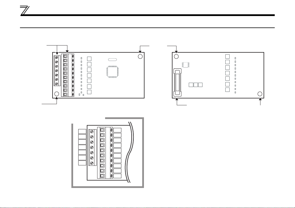
1.2 Parts
Terminal
block
Mounting
hole
2
Front view
Terminal layout
X10
X11
X12
X13
X14
X15
DY
X0
X1
X2
X3
X4
X5
X6
X7
X8
X9
Mounting
hole
Rear view
Connector
Connect to the inverter
option connector
(Refer to page 5, 7.)
Mounting hole

1.3 Specifications
(1) Digital input signal type
BCD code 3-digit or 4-digit
Binary 12-bit or binary 16-bit
(2) Selection of digital input signal
Select from the operation panel or parameter unit.
(3) Input current
5mA(24VDC) for each circuit
(4) Input specifications
Relay contact signal or open collector input
(5) Adjustment function
⋅ Bias and gain
PRE-OPERATION INSTRUCTIONS
1
3
2
INSTALLATION AND WIRING
2.1 Pre-Installation Instructions
Make sure that the input power of the inverter is off.
CAUTION
With input power on, do not install or remove the plug-in option. Otherwise, the inverter and
plug-in option may be damaged.
For prevention of damage due to static electricity, touch nearby metal before touching this
product to eliminate static electricity from your body.
2.2 Installation Procedure
CAUTION
• Always perform wiring to the main circuit terminals and control circuit terminals before installing the
option. Wiring cannot be performed after installing the option.
• When mounting the plug-in option, do not let wires get caught in the plug-in option or the spacer for option
mounting. If a wire gets caught, the inverter and the plug-in option may be damaged.
• When the inverter cannot recognize that the option is mounted due to improper installation, etc., " "
(option fault) is displayed.
• Take care not to drop a mounting screws during mounting and removal.
• Pull out the option straight to remove. Otherwise, the connector may be damaged.
REMARKS
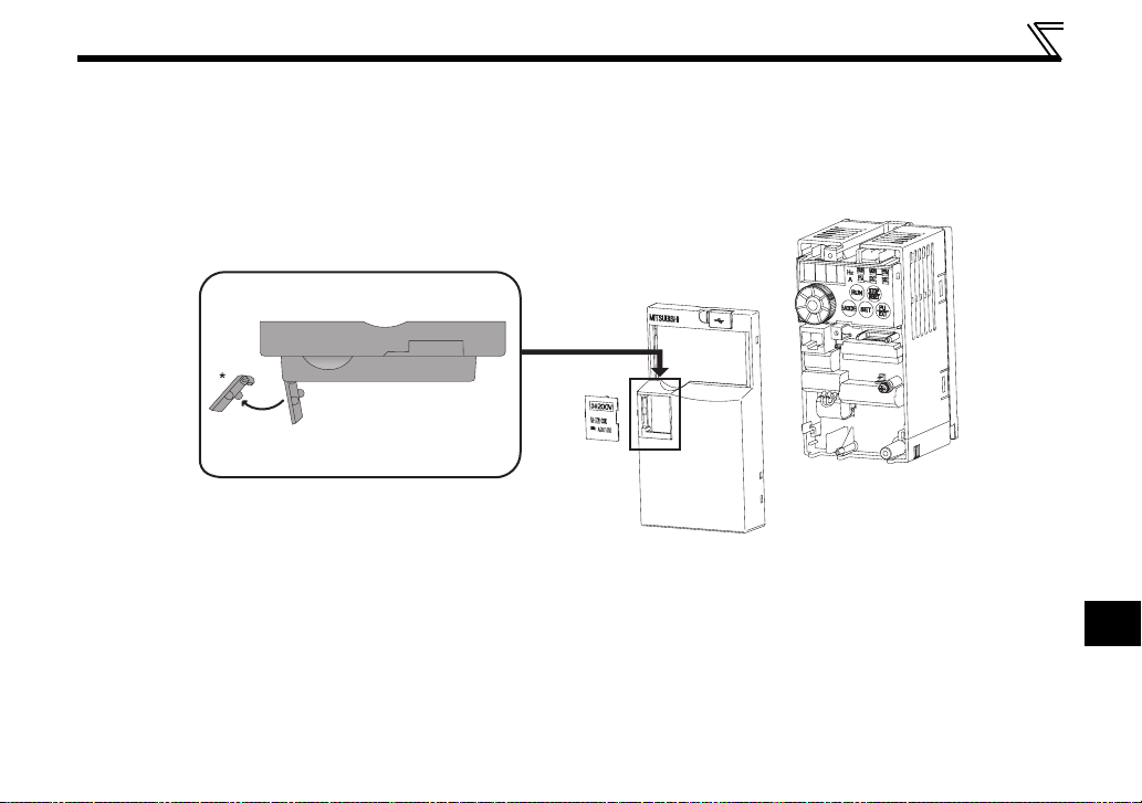
• Bcause the voltage class, model name and serial number (only voltage class is labeled for FR-E720-5.5KSC (FR-
E720-240SC), FR-E740-5.5KSC (FR-E740-120SC) or higher) are written on the PU cover, replace the PU cover of
the plug-in option with the removed PU cover of the inverter.
4
INSTALLATION AND WIRING
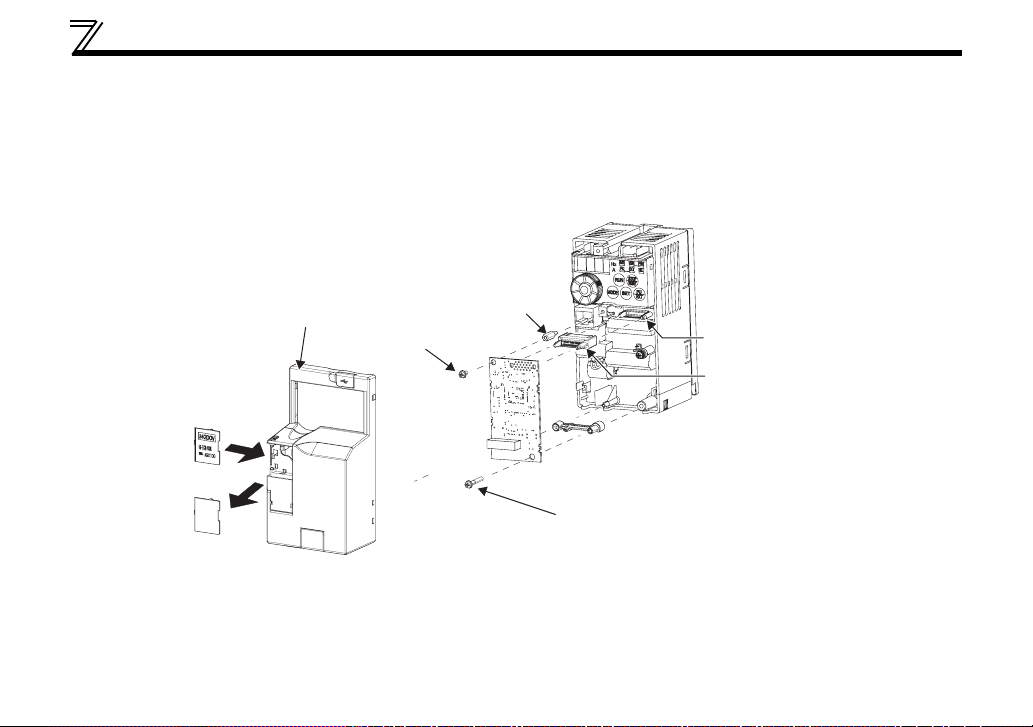
z Inverter with one front cover
(1) Remove the front cover from the inverter. (For removing the front cover, refer to the FR-E700 series
instruction manual.)
(2) Remove the PU cover from the front cover. Open the PU cover with a driver, etc. and remove it in the
direction of arrow as shown below.
(1) Front cover
(2) PU cover
* Open the PU cover, then open it toward the arrow
direction to remove.
(3) Fit the spacer for plug-in option mounting, the hexagon spacer, and the junction connector into their
designated positions shown in the diagram on the next page. Fit the junction connector along the guide
of the connector of the inverter and insert it as far as it goes.
(4) Fit the connector of the plug-in option along the guide of the junction connector and insert it as far as it
goes.
(5) Fix the plug-in option securely by using the supplied mounting screw (short) to the upper screw hole and
the other supplied mounting screw (long) to the lower screw hole of the plug-in option. If the screw holes
do not line up, the connector may not have been plugged properly. Check for loose plugging.
Tightening torque: 0.33 to 0.4
N⋅m
2
5
INSTALLATION AND WIRING
(6) Remove the PU cover provided on the front cover for plug-in option and mount the other PU cover,
which was removed in (2).
(7) Loosen the terminal screws and insert the wires into the terminals. After that, fasten the terminal screws
to the recommended tightening torque. (Refer to page 9)
(8) After wiring of the plug-in option has been completed, mount the front cover for the plug-in option to the
inverter.
(6) Replace
Front cover
for plug-in option
(5) Mounting screws
(8)
(short)
(3) Hexagon
spacer
(4)
(7)
(3) Plug-in option connector
of inverter
(3) Junction connector
(3) Spacer for plug-in option mounting
(5) Mounting screw (long)
6
 Loading...