

Mitsubishi Electric FR-A7AX Instruction Manual

INSTRUCTION MANUAL
1
INVERTER
Plug-in option
FR-A7AX
16 bit digital input function
PRE-OPERATION INSTRUCTIONS
INSTALLATION AND WIRING
A7AX.book1ページ2005年9月22日 木曜日 午後7時40分
Thank you for choosing this Mitsubishi Inverter plug-in option.
This instruction manual gives handling information and
precautions for use of this equipment. Incorrect handling might
cause an unexpected fault. Before using the equipment, please
read this manual carefully to use the equipment to its optimum.
Please forward this manual to the end user.
1. Electric Shock Prevention
This section is specifically about
safety matters
Do not attempt to install, operate, maintain or inspect this
product until you have read through this instruction manual and
appended documents carefully and can use the equipment
correctly. Do not use this product until you have a full
knowledge of the equipment, safety information and
instructions.
In this instruction manual, the safety instruction levels are
classified into "WARNING" and "CAUTION".
Assumes that incorrect handling may
cause hazardous conditions, resulting
in death or severe injury.
Assumes that incorrect handling may
cause hazardous conditions, resulting
in medium or slight injury, or may
cause physical damage only.
Note that even the level may lead to a serious
consequence according to conditions. Please follow the
instructions of both levels because they are important to
WARNING
CAUTION
CAUTION
SAFETY INSTRUCTIONS
WARNING
• While power is on or when the inverter is running, do not
open the front cover. You may get an electric shock.
• Do not run the inverter with the front cover or wiring cover
removed. Otherwise, you may access the exposed highvoltage terminals and charging part and get an electric shock.
• If power is off, do not remove the front cover except for wiring
or periodic inspection. You may access the charged inverter
circuits and get an electric shock.
• Before starting wiring or inspection, check to make sure that
Indication of the inverter operation panel is off, wait for at least
10 minutes after the power supply has been switched off, and
check that there are no residual voltage using a tester or the
like. The capacitor is charged with high voltage for some time
after power off and it is dangerous.
• Any person who is involved in the wiring or inspection of this
equipment should be fully competent to do the work.
• Always install the plug-in option before wiring. Otherwise,
you may get an electric shock or be injured.
• Do not touch the plug-in option with wet hands. Otherwise
you may get an electric shock.
• Do not subject the cables to scratches, excessive stress,
heavy loads or pinching. Otherwise you may get an electric
shock.
A7AX.book1ページ2005年9月22日 木曜日 午後7時40分
2. Injury Prevention
3. Additional Instructions
Also note the following points to prevent an accidental failure,
injury, electric shock, etc.
1) Transportation and mounting
2) Trial run
3) Usage
4) Maintenance, inspection and parts replacement
5) Disposal
CAUTION
• Apply only the voltage specified in the instruction manual to
each terminal. Otherwise, burst, damage, etc. may occur.
• Ensure that the cables are connected to the correct terminals.
Otherwise, burst, damage, etc. may occur.
• Always make sure that polarity is correct to prevent damage, etc.
Otherwise, burst, damage may occur.
• While power is on or for some time after power-off, do not touch
the inverter as it is hot and you may get burnt.
CAUTION
• Do not install or operate the plug-in option if it is damaged or
has parts missing.
• Do not stand or rest heavy objects on the product.
• Check that the mounting orientation is correct.
• Prevent other conductive bodies such as screws and metal
fragments or other flammable substance such as oil from
entering the inverter.
WARNING
• Do not modify the equipment.
• Do not perform parts removal which is not instructed in this
manual. Doing so may lead to fault or damage of the inverter.
CAUTION
• When parameter clear or all parameter clear is performed,
reset the required parameters before starting operations.
Each parameter returns to the initial value.
• For prevention of damage due to static electricity, touch
nearby metal before touching this product to eliminate static
electricity from your body.
CAUTION
• Do not test the equipment with a megger (measure insulation
resistance).
CAUTION
• Treat as industrial waste.
A7AX.book2ページ2005年9月22日 木曜日 午後7時40分

CONTENTS
1 PRE-OPERATION INSTRUCTIONS 1
1.1 Unpacking and Product Confirmation .............................................................................................1
1.1.1 Packing confirmation ......................................................................................................................................1
1.1.2 Parts ...............................................................................................................................................................2
1.1.3 Specifications .................................................................................................................................................3
2 INSTALLATION AND WIRING 4
2.1 Pre-Installation Instructions .............................................................................................................4
2.2 Installation Procedure .......................................................................................................................5
2.3 Wiring..................................................................................................................................................7
3 CONNECTION DIAGRAM AND TERMINAL 9
3.1 Connection Diagram..........................................................................................................................9
3.2 Internal Block Diagram....................................................................................................................11
3.3 Terminals..........................................................................................................................................12
3.4 Code Input Example ........................................................................................................................13
4 PARAMETERS 14
4.1 Parameter List ..................................................................................................................................14
4.2 Parameter Setting ............................................................................................................................16
A7AX.book1ページ2005年9月22日 木曜日 午後7時40分
1
1 PRE-OPERATION INSTRUCTIONS
1.1 Unpacking and Product Confirmation
Take the plug-in option out of the package, check the unit name, and confirm that the product is as you
ordered and intact.
This product is a plug-in option dedicated for the FR-A
700/F700 series.
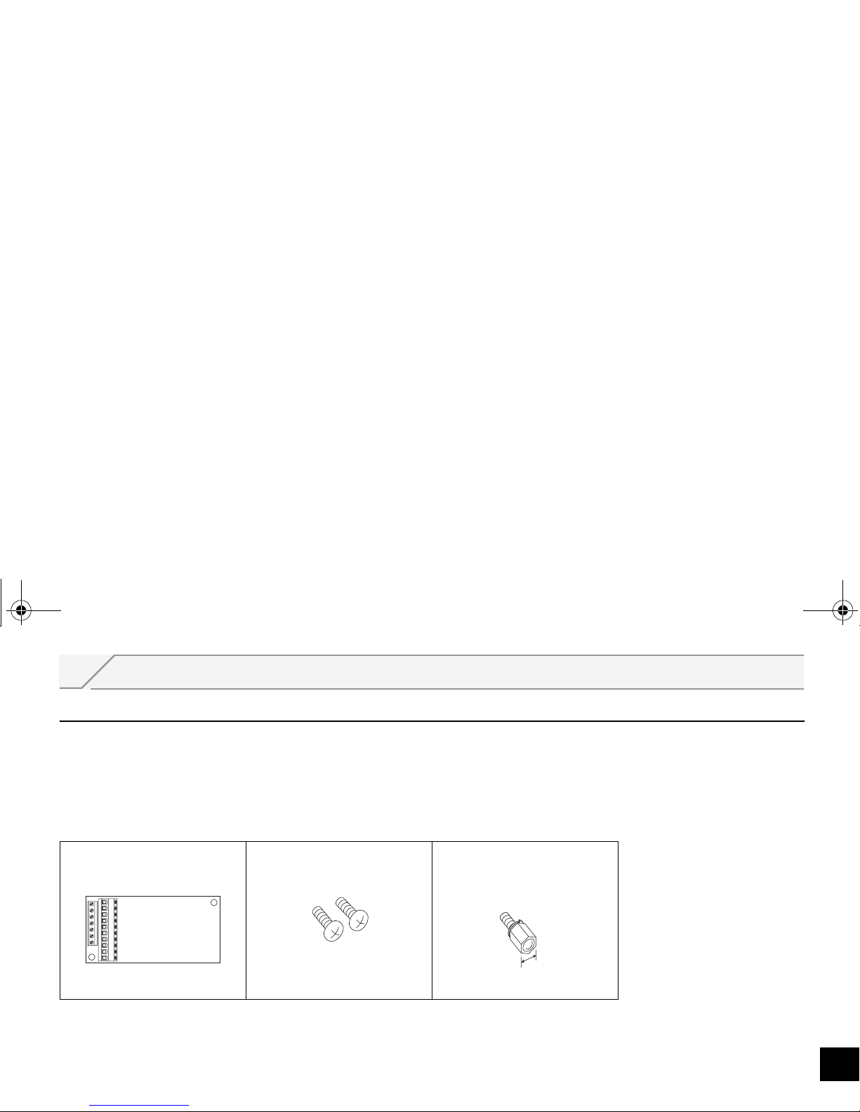
1.1.1 Packing confirmation
Check the enclosed items.
Plug-in option
......................................... 1
Mounting screw (M3 × 6mm)
.............. 2 (Refer to page 5.)
Hex-head screw for option
mounting (5.5mm)
...............1 (Refer to page 5.)
5.5mm
A7AX.book1ページ2005年9月22日 木曜日 午後7時40分
PRE-OPERATION INSTRUCTIONS
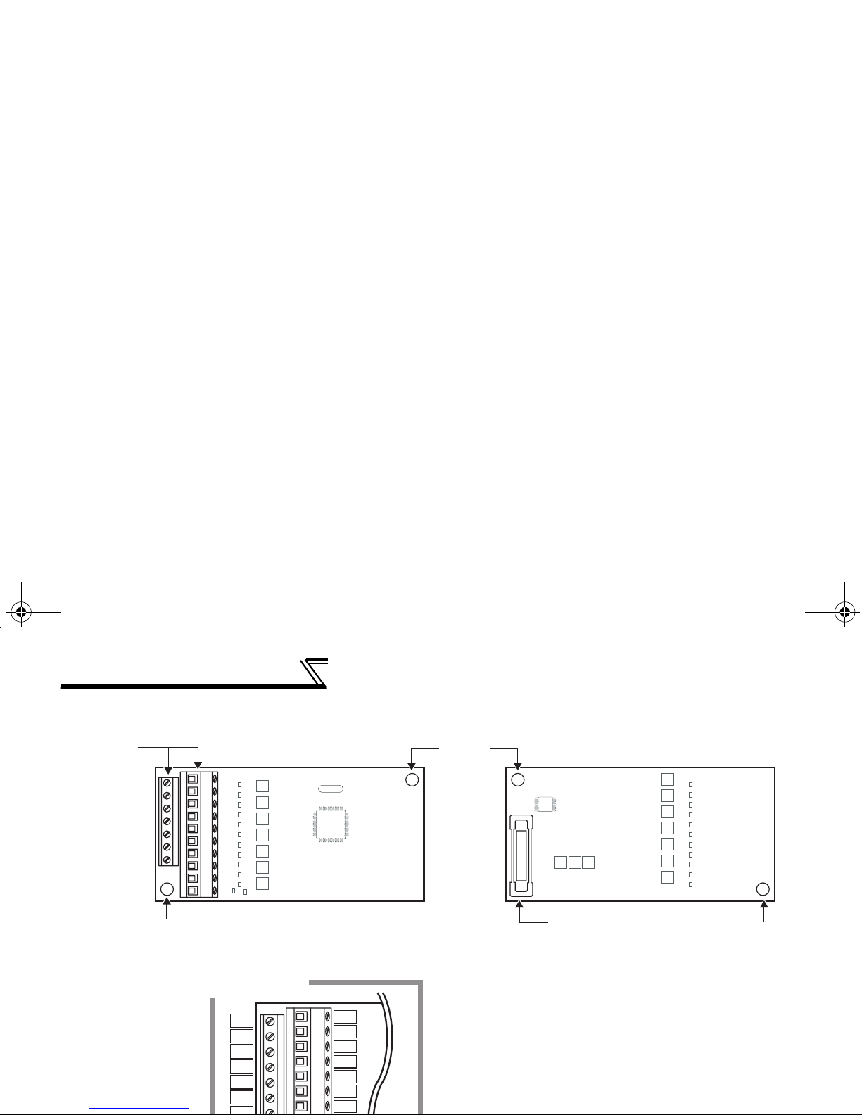
1.1.2 Parts
X10
X11
X12
X13
X14
X15
X0
X1
X2
X3
X4
X5
X6
Front view
Terminal layout
Rear view
Mounting
hole
Mounting hole
Mounting
hole
Terminal
block
Connector
Connect to the inverter
option connector
(Refer to page 5.)
A7AX.book2ページ2005年9月22日 木曜日 午後7時40分
PRE-OPERATION INSTRUCTIONS
1
1.1.3 Specifications
(1) Digital input signal type
BCD code 3 digits or 4 digits
Binary 12 bits or binary 16 bits
(2) Selection of digital input signal
Select from the operation panel or parameter unit.
(3) Input current
5mA(24VDC) for each circuit
(4) Input specifications
Contact signal or open collector input
(5) Adjustment function
⋅ Bias and gain
⋅ Analog compensation input
(Set using the operation panel)
A7AX.book3ページ2005年9月22日 木曜日 午後7時40分
2 INSTALLATION AND WIRING
2.1 Pre-Installation Instructions
Make sure that the input power of the inverter is off.
CAUTION
With input power on, do not install or remove the plug-in option. Otherwise, the inverter and
plug-in option may be damaged.
A7AX.book4ページ2005年9月22日 木曜日 午後7時40分
INSTALLATION AND WIRING
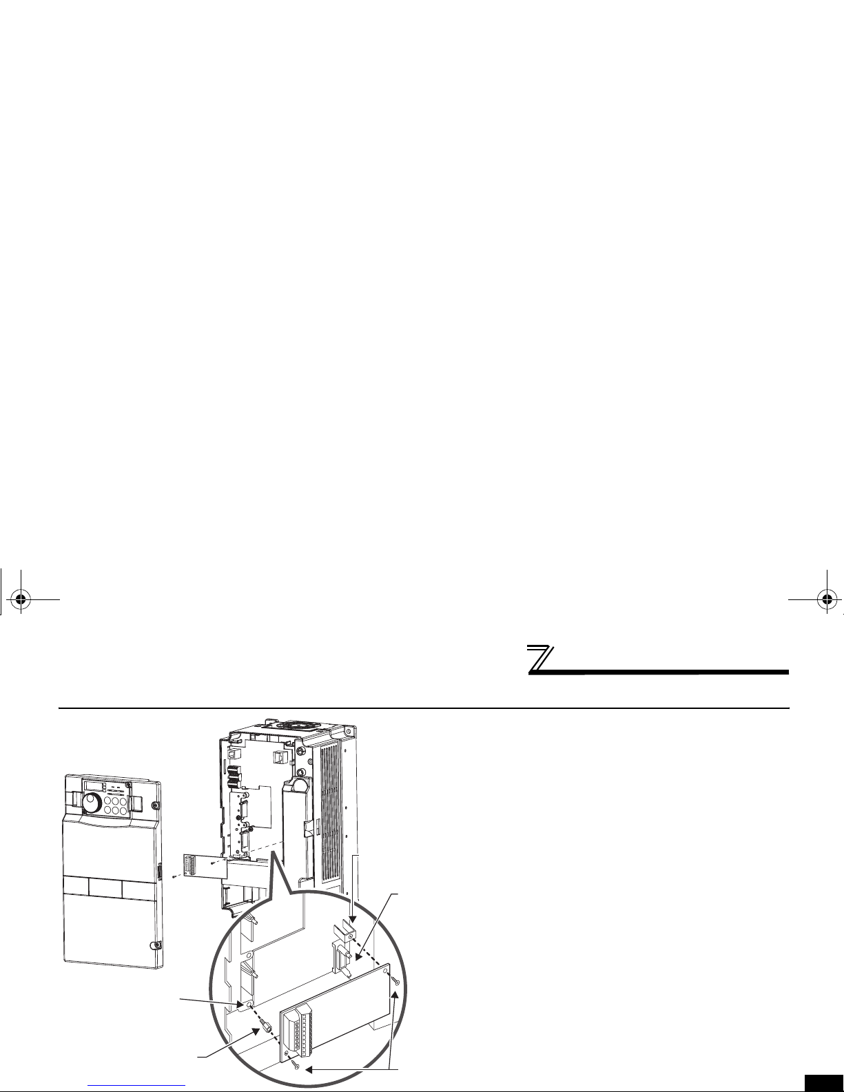
2.2 Installation Procedure
1) Remove the inverter front cover.
2) Mount the hex-head screw for option
mounting into the inverter screw hole (on
earth plate). (size 5.5mm, tightening
torque 0.56N⋅m to 0.75N⋅m)
3) Securely fit the connector of the plug-in
option to the inverter connector along the
guides.
4) Securely fix the both right and left sides
of the plug-in option to the inverter with
the accessory mounting screws. If the
screw holes do not line-up, the connector
may not have been plugged snugly.
Check for loose plugging.
4)
Mounting
screws
Inverter side
option
connector
Screw hole for
option mounting
Screw hole for
option mounting
(on earth plate)
Hex-head screw
for option mounting
1)
2)
3)
A7AX.book5ページ2005年9月22日 木曜日 午後7時40分
INSTALLATION AND WIRING
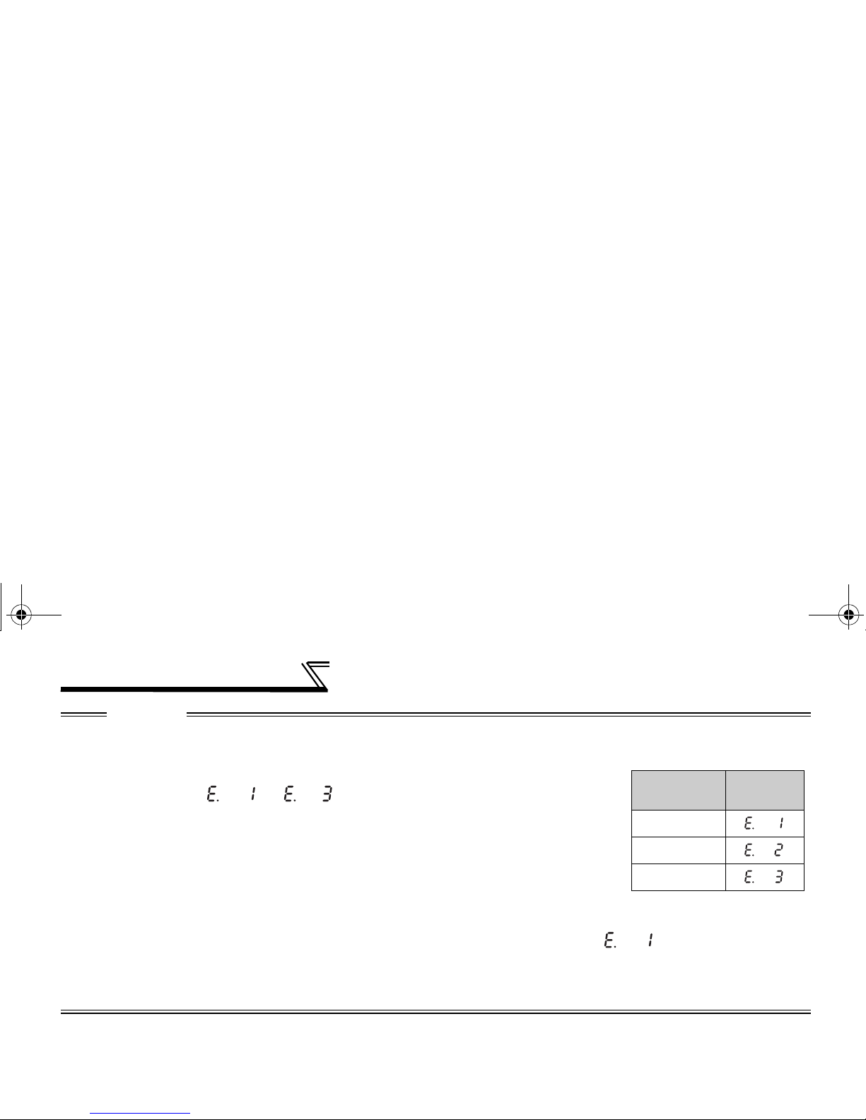
CAUTION
• When two or more options are mounted, priority is in order of inverter option connectors 1, 2 and 3, the
options having lower priority are inoperative.
• When the inverter cannot recognize that the option is mounted due to improper
installation, etc., " to " (option alarm) are displayed for the FRA700 series.The errors shown differ according to the mounting positions
(connectors 1, 2, 3).
• The FR-F700 series has one connection connector for the plug-in option. When the inverter can not
recognize that the option unit is mounted due to improper installation, etc., " " (option alarm) is
displayed.
• Take care not to drop a hex-head screw for option mounting or mounting screw during mounting and removal.
• Pull out the option straight to remove. Otherwise, the connector may be damaged by some applied force.
Mounting
Position
Error
Display
Connector 1
Connector 2
Connector 3
A7AX.book6ページ2005年9月22日 木曜日 午後7時40分
 Loading...