

Mitsubishi Electric FR-A7AR, FR-A7AR E Instruction Manual

INVERTER
Plug-in option
FR-A7AR
FR-A7AR E kit
INSTRUCTION MANUAL
Relay output function
PRE-OPERATION INSTRUCTIONS
INSTALLATION AND WIRING
(FR-A700/F700 SERIES)
INSTALLATION AND WIRING
(FR-E700 SERIES (E kit))
RELAY OUTPUT
1
2
3
4
Thank you for choosing this Mitsubishi Electric inverter plug-in
WARNING
CAUTION
CAUTION
option.
This Instruction Manual provides handling information and
precautions for use of this product. Incorrect handling might
cause an unexpected fault. Before using this product, read all
relevant instruction manuals carefully to ensure proper use.
Please forward this Instruction Manual to the end user.
This section is specifically about
safety matters
Do not attempt to install, operate, maintain or inspect this
product until you have read this Instruction Manual and
supplementary documents carefully. Do not use this product
until you have a full knowledge of this product mechanism,
safety information and instructions.
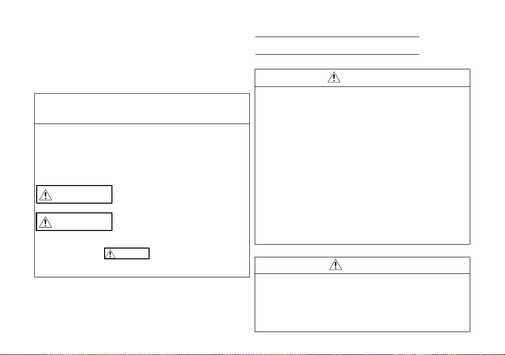
In this Instruction Manual, the safety instruction levels are
classified into "WARNING" and "CAUTION".
Incorrect handling may cause hazardous
conditions, resulting in death or severe
injury.
Incorrect handling may cause hazardous
conditions, resulting in medium or slight
injury, or may cause only material
damage.
Note that even the level may lead to a serious
consequence depending on conditions. Be sure to follow the
instructions of both levels as they are critical to personnel safety.
SAFETY INSTRUCTIONS
1. Electric shock prevention
WARNING
Do not remove the front cover or the wiring cover of the
inverter while the inverter power is ON. Do not operate the
inverter with any cover or wiring cover removed, as accidental
contact with exposed high-voltage terminals and internal
components may occur, resulting in an electrical shock.
Even if power is OFF, do not remove the front cover of the
inverter except for wiring or periodic inspection as you may
accidentally touch the charged circuits and get an electric shock.
Before wiring or inspection, check that the display of the
inverter operation panel is OFF. Any person who is involved in
wiring or inspection shall wait for 10 minutes or longer after
power OFF and check that there are no residual voltage using a
tester or the like. The capacitor is charged with high voltage for
some time after power OFF, and it is dangerous.
Any person who is involved in wiring or inspection of this
product shall be fully competent to do the work.
This product must be installed before wiring. Otherwise you
may get an electric shock or be injured.
Do not subject the cables to scratches, excessive stress, heavy
loads or pinching. Doing so may cause an electric shock.
Do not touch this product or handle the cables with wet hands.
Doing so may cause an electric shock.
2. Injury prevention
CAUTION
The voltage applied to each terminal must be as specified in the
Instruction Manual. Otherwise an explosion or damage may occur.
The cables must be connected to the correct terminals.
Otherwise
The polarity (+ and -) must be correct. Otherwise
or damage
While power is ON or for some time after power OFF, do not touch
the inverter as it will be extremely hot. Doing so may cause burns.
an explosion or damage
may occur.
may occur.
an explosion
A-1
3. Additional instructions
The following instructions must be also followed. If this product is
handled incorrectly, it may cause unexpected fault, an injury, or an
electric shock.
1) Transportation and installation
CAUTION
Do not install or operate the plug-in option if it is damaged or
has parts missing.
Do not stand or place heavy objects on this product.
Ensure the mounting orientation of this product is correct.
Foreign conductive objects must be prevented from entering
the inverter. That includes screws and metal fragments or
other flammable substance such as oil.
If halogens (including fluorine, chlorine, bromine, and iodine),
contained in fumigants for wood packages enter this product,
the product may be damaged. Prevent the entry of fumigant
residuals or use an alternative method such as heat
disinfection. Note that sterilization or disinfection of wood
packages should also be performed before packing the
product.
2) Test operation
CAUTION
Before starting operation, confirm or adjust the parameter
settings. Failure to do so may cause some machines to make
unexpected motions.
3) Usage
WARNING
Do not modify this product.
Do not remove any part which is not instructed to be removed
in the Instruction Manuals. Doing so may lead to a failure or
damage of this product.
CAUTION
As all parameters return to their initial val ues af ter Paramet er clear
or All parameter clear is performed, the needed parameters for
operation of the inverter and this product must be set again before
the operation is started.
To avoid damage to this product due to static electricity, static
electricity in your body must be discharged before you touch
this product.
4) Maintenance, inspection and parts replacement
CAUTION
Do not carry out a megger (insulation resistance) test.
5) Disposal
CAUTION
This product must be treated as industrial waste.
6) General instruction
For clarity, illustrations in this Instruction Manual may be drawn
with covers or safety guards removed. Ensure all covers and
safety guards are properly installed prior to starting operation.
A-2

— CONTENTS —
1 PRE-OPERATION INSTRUCTIONS 1
1.1 Unpacking and Product Confirmation .............................................................................................1
1.1.1 Packing confirmation (FR-A700/F700 series).................................................................................................1
1.1.2 Packing confirmation (FR-E700 series (E kit)) ............................................................................................... 2
1.2 Parts....................................................................................................................................................3
1.3 Specifications.....................................................................................................................................4
2 INSTALLATION AND WIRING (FR-A700/F700 SERIES) 5
2.1 Pre-Installation Instructions .............................................................................................................5
2.2 Installation Procedure .......................................................................................................................6
2.3 Wiring..................................................................................................................................................8
3 INSTALLATION AND WIRING (FR-E700 SERIES (E kit)) 11
3.1 Pre-Installation Instructions ...........................................................................................................11
3.2 Installation Procedure .....................................................................................................................11
3.3 Wiring................................................................................................................................................17
4 RELAY OUTPUT 20
4.1 Internal Block Diagram....................................................................................................................20
4.2 Terminals ..........................................................................................................................................21
4.3 Parameter List ..................................................................................................................................21
4.4 Output Signal List (FR-A700/F700 series) .....................................................................................22
4.5 Output Signal List (FR-E700 series)...............................................................................................24
4.6 Connection Diagram When Using Electronic Bypass Sequence Function (FR-A700/F700
series) ...............................................................................................................................................25
I

APPENDIX 26
Appendix 1 Instructions for compliance with the EU Directives .......................................................26
Appendix 2 Instructions for EAC ..........................................................................................................27
Appendix 3 Restricted Use of Hazardous Substances in Electronic and Electrical Products........28
Appendix 4 Referenced Standard (Requirement of Chinese standardized law) ..............................29
II
1 PRE-OPERATION INSTRUCTIONS
1.1 Unpacking and Product Confirmation
Take the plug-in option out of the package, check the product name, and confirm that the product is as you
ordered and intact.
This product is a plug-in option dedicated for the FR-A
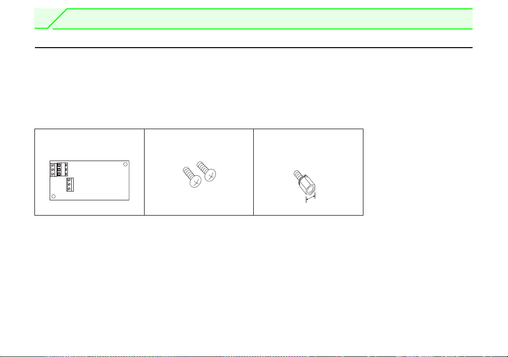
1.1.1 Packing confirmation (FR-A700/F700 series)
Check the enclosed items.
Plug-in option
......................................... 1
Mounting screw (M3 6mm)
.............. 2 (Refer to page 6.)
700/F700/E700 series.
Hex-head screw for option
mounting (5.5mm)
............... 1 (Refer to page 6.)
5.5mm
1
PRE-OPERATION INSTRUCTIONS
1
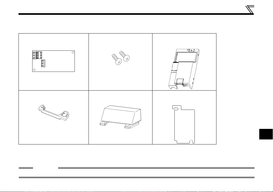
1.1.2 Packing confirmation (FR-E700 series (E kit))
Check the enclosed items.
Plug-in option
............................................... 1
Mounting screw (M3 6mm)
............ 2
(Refer to page 13, 16)
Front cover for plug-in option
...............1
(Refer to page 13, 16)
Option protective cover
...................... 1
*1 Used with the FR-E720-3.7K (FR-E720-175) or less and FR-E740-7.5K (FR-E740-170) or less.
*2 Used with the FR-E720-5.5K (FR-E720-240) or more and FR-E740-11K (FR-E740-230) or more.
*1
(Refer to page 13)
Option small cover
................... 1
(Refer to page 16)
*2
Insulation sheet
...............1
(Refer to page 13, 16)
CAUTION
• In place of the inverter front cover, install a provided front cover for plug-in option.
2
PRE-OPERATION INSTRUCTIONS
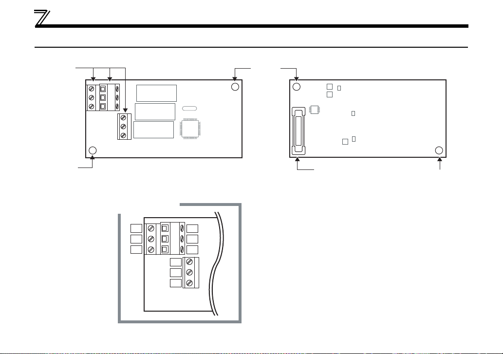
Front view
Terminal layout
Rear view
Mounting
hole
Mounting hole
Mounting
hole
Terminal
block
Connector
Connect to the inverter
option connector
2A
2B
2C
1A
1B
1C
3A
3B
3C
(Refer to page 13, 16)
1.2 Parts
3

PRE-OPERATION INSTRUCTIONS
1.3 Specifications
(1) Types of output signal
1 changeover contact output (three relays are provided)
(2) Contact capacity
230VAC .......... 0.3A
30VDC............ 0.3A
CAUTION
• The contacts should be used within the rated capacity to prevent contacts weld resulting from faster
contacts wearing.
1
4
2 INSTALLATION AND WIRING (FR-A700/F700 SERIES)
2.1 Pre-Installation Instructions
Make sure that the input power of the inverter is off.
CAUTION
With input power on, do not install or remove the plug-in option. Otherwise, the inverter and
plug-in option may be damaged.
For prevention of damage due to static electricity, touch nearby metal before touching this
product to eliminate static electricity from your body.
5
2
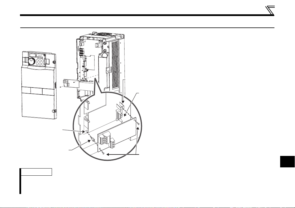
2.2 Installation Procedure
4)
Mounting
screws
Inverter side
option
connector
Screw hole for
option mounting
Screw hole for
option mounting
(on earth plate)
Hex-head screw
for option mounting
1)
2)
3)
REMARKS
• Remove a plug-in option after removing two screws on both left and right sides.
(When the plug-in option is mounted in the connector 3 (connector 1 for the FR-F
the plug-in option after removing a control circuit terminal block.)
INSTALLATION AND WIRING (FR-A700/F700 SERIES)
1)Remove the inverter front cover.
2)Mount the hex-head screw for option
mounting into the inverter screw hole
(on earth plate). (size 5.5mm,
tightening torque 0.56Nm to 0.75Nm)
3)Securely fit the connector of the plug-in
option to the inverter connector along
the guides.
4)Securely fix the both right and left sides
of the plug-in option to the inverter with
the accessory mounting screws.
(Tightening torque 0.33Nm to
0.40Nm) If the screw holes do not lineup, the connector may not have been
plugged snugly. Check for loose
plugging.
700 series), it is easier to remove
6
 Loading...