

Page 1

INVERTER
Plug-in option
FR-A7AP
INSTRUCTION MANUAL
Orientation control
Encoder feedback control
Vector control
PRE-OPERATION INSTRUCTIONS
1
INSTALLATION
2
ORIENTATION CONTROL
3
ENCODER FEEDBACK CONTROL
VECTOR CONTROL
4
5
Page 2
Thank you for choosing this Mitsubishi Inverter plug-in option.
This Instruction Manual gives handling information and
precautions for use of this equipment. Incorrect handling might
cause an unexpected fault. Before using the equipment, please
read this manual carefully to use the equipment to its optimum.
Please forward this manual to the end user.
This section is specifically about
safety matters
Do not attempt to install, operate, maintain or inspect this
product until you have read through this Instruction Manual and
appended documents carefully and can use the equipment
correctly. Do not use this product until you have a full
knowledge of the equipment, safety information and
instructions.
In this Instruction Manual, the safety instruction levels are
classified into "WARNING" and "CAUTION".
Incorrect handling may cause
WARNING
CAUTION
The level may even lead to a serious
consequence according to conditions. Both instruction levels
must be followed because these are important to personal
safety.
CAUTION
hazardous conditions, resulting in
death or severe injury.
Incorrect handling may cause
hazardous conditions, resulting in
medium or slight injury, or may cause
only material damage.
SAFETY INSTRUCTIONS
1. Electric Shock Prevention
WARNING
• While the inverter power is ON, do not open the front cover or
the wiring cover. Do not run the inverter with the front cover
or the wiring cover removed. Otherwise you may access the
exposed high voltage terminals or the charging part of the
circuitry and get an electric shock.
• Even if power is OFF, do not remove the front cover except for
wiring or periodic inspection. You may accidentally touch the
charged inverter circuits and get an electric shock.
• Before wiring or inspection, power must be switched OFF. To
confirm that, LED indication of the operation panel must be
checked. (It must be OFF.) Any person who is involved in
wiring or inspection shall wait for at least 10 minutes after the
power supply has been switched OFF and check that there
are no residual voltage using a tester or the like. The
capacitor is charged with high voltage for some time after
power OFF, and it is dangerous.
• Any person who is involved in wiring or inspection of this
equipment shall be fully competent to do the work.
• The plug-in option must be installed before wiring. Otherwise,
you may get an electric shock or be injured.
• Do not touch the plug-in option or handle the cables with wet
hands. Otherwise you may get an electric shock.
• Do not subject the cables to scratches, excessive stress,
heavy loads or pinching. Otherwise you may get an electric
shock.
A-1
Page 3
2. Injury Prevention
3) Usage
CAUTION
• The voltage applied to each terminal must be the ones
specified in the Instruction Manual. Otherwise burst, damage,
etc. may occur.
• The cables must be connected to the correct terminals.
Otherwise burst, damage, etc. may occur.
• Polarity must be correct. Otherwise burst, damage, etc. may
occur.
• While power is ON or for some time after power-OFF, do not
touch the inverter as they will be extremely hot. Doing so can
cause burns.
3. Additional Instructions
Also the following points must be noted to prevent an accidental
failure, injury, electric shock, etc.
1) Transportation and mounting
CAUTION
• Do not install or operate the plug-in option if it is damaged or
has parts missing.
• Do not stand or rest heavy objects on the product.
• The mounting orientation must be correct.
• Foreign conductive objects must be prevented from entering
the inverter. That includes screws and metal fragments or
other flammable substances such as oil.
2) Trial run
CAUTION
• Before starting operation, each parameter must be confirmed
and adjusted. A failure to do so may cause some machines to
make unexpected motions.
WARNING
• Do not modify the equipment.
• Do not perform parts removal which is not instructed in this
manual. Doing so may lead to fault or damage of the inverter.
CAUTION
•
When parameter clear or all parameter clear is performed, the
required parameters must be set again before starting operations
because all parameters return to the initial value.
• For prevention of damage due to static electricity, nearby
metal must be touched before touching this product to
eliminate static electricity from your body.
4) Maintenance, inspection and parts replacement
CAUTION
• Do not test the equipment with a megger (measure insulation
resistance).
5) Disposal
CAUTION
• This inverter plug-in option must be treated as industrial
waste.
6) General instruction
Many of the diagrams and drawings in this Instruction Manual
show the inverter without a cover or partially open for
explanation. Never operate the inverter in this manner. The
cover must be reinstalled and the instructions in the inverter
manual must be followed when operating the inverter.
A-2
Page 4

MEMO
A-3
Page 5

⎯ CONTENTS ⎯
1 PRE-OPERATION INSTRUCTIONS 1
1.1 Unpacking and Product Confirmation .............................................................................................1
1.1.1 Product confirmation....................................................................................................................................... 1
1.1.2 SERIAL number check ................................................................................................................................... 2
1.2 Parts ....................................................................................................................................................3
2 INSTALLATION 4
2.1 Pre-installation instructions .............................................................................................................4
2.2 Installation procedure .......................................................................................................................5
2.3 Encoder Specifications/Terminating Resistor Switch....................................................................7
2.4 Wiring..................................................................................................................................................9
2.5 Encoder Cable ..................................................................................................................................13
2.6 Encoder.............................................................................................................................................15
2.7 Parameter for Encoder ....................................................................................................................17
3 ORIENTATION CONTROL 19
3.1 Wiring Example ................................................................................................................................19
3.2 Terminals ..........................................................................................................................................21
3.3 Parameter List for Orientation Control ..........................................................................................24
3.4 Specifications...................................................................................................................................25
I
Page 6

4 ENCODER FEEDBACK CONTROL 27
4.1 Wiring Examples ..............................................................................................................................27
4.2 Terminals ..........................................................................................................................................29
4.3 Encoder Feedback Control Parameter List ...................................................................................30
4.4 Specifications...................................................................................................................................30
5 VECTOR CONTROL 31
5.1 Wiring Examples ..............................................................................................................................31
5.2 Terminals ..........................................................................................................................................35
5.3 Vector Control Extended Parameter List.......................................................................................36
5.4 Specifications...................................................................................................................................39
II
Page 7
1 PRE-OPERATION INSTRUCTIONS
1.1 Unpacking and Product Confirmation
Take the plug-in option out of the package, check the product name, and confirm that the product is as you
ordered and intact.
This product is a plug-in option dedicated for the FR-A
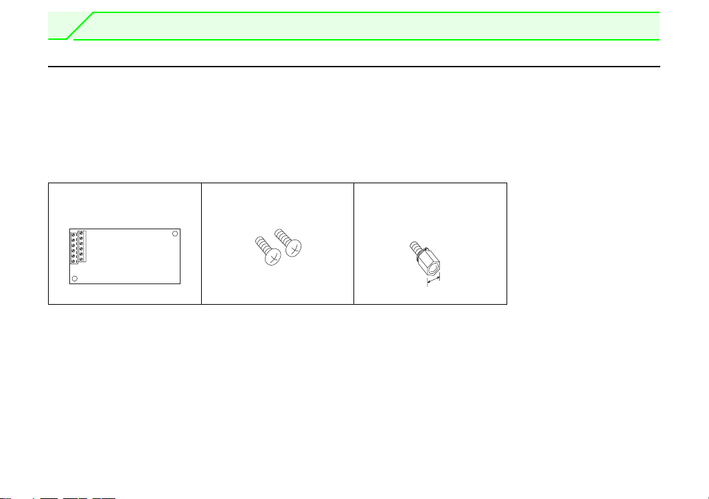
1.1.1 Product confirmation
Check the enclosed items.
Plug-in option
......................................... 1
Mounting screw (M3 × 6mm)
.............. 2 (Refer to page 5.)
700/A701 series.
Hex-head screw for option
mounting (5.5mm)
...............1 (Refer to page 5.)
5.5mm
1
Page 8
PRE-OPERATION INSTRUCTIONS
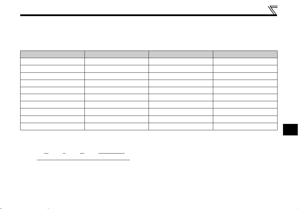
1.1.2 SERIAL number check
When you are using FR-A7AP with an FR-A700 series inverter, check the SERIAL number on the FRA700. The FR-A700 series inverters having the following SERIAL or later are compatible with FR-A7AP.
The SERIAL number is specified on the inverter rating plate or package.
Model SERIAL (Serial No.) Model SERIAL (Serial No.)
FR-A720-0.4K/0.75K P5{{{{{{{ FR-A740-0.4K L5{{{{{{{
FR-A720-1.5K/2.2K Q5{{{{{{{ FR-A740-0.75K K5{{{{{{{
FR-A720-3.7K N5{{{{{{{ FR-A740-1.5K/2.2K J5{{{{{{{
FR-A720-5.5K to 11K L5{{{{{{{ FR-A740-3.7K H5{{{{{{{
FR-A720-15K to 22K M5{{{{{{{ FR-A740-5.5K/7.5K G5{{{{{{{
FR-A720-30K Q5{{{{{{{ FR-A740-11K to 22K F5{{{{{{{
FR-A720-37K M5{{{{{{{ FR-A740-30K to 55K E5{{{{{{{
FR-A720-45K L5{{{{{{{ FR-A740-75K/90K G5{{{{{{{
FR-A720-55K K5{{{{{{{ FR-A740-110K to 160K E5{{{{{{{
FR-A720-75K/90K E5{{{{{{{ FR-A740-185K to 500K C5{{{{{{{
Rating plate example
1
Symbol Year Month Control number
The SERIAL consists of 1 version symbol, 2 numeric characters or
1 numeric character and 1 alphabet letter indicating year and
month, and 6 numeric characters indicating control number.
The last digit of the production year is indicated as the Year, and
the Month is indicated by 1 to 9, X (October), Y (November), or Z
(December.)
5 { {{{{{{
SERIAL (Serial No.)
2
Page 9
PRE-OPERATION INSTRUCTIONS
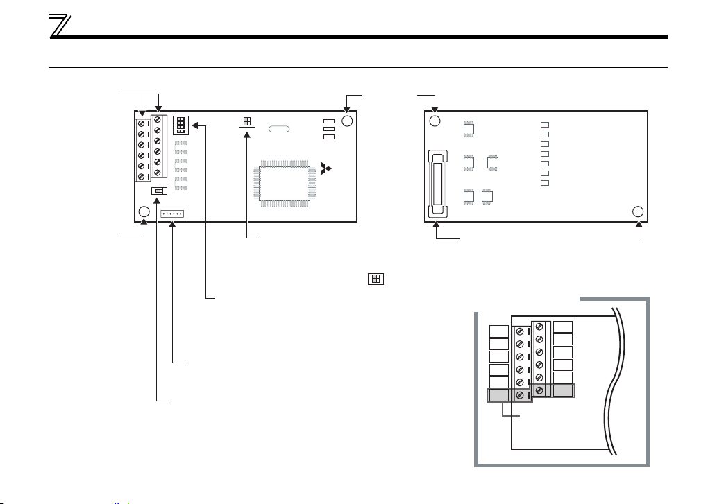
1.2 Parts
Mounting
3
Terminal
block
hole
LED1
LED2
LED3
Mounting
SW1
Front view Rear view
4
SW2
3
2
N
1
O
SW3
2
N
1
O
FR-A7AP
Switch for manufacturer
setting (SW3)
Do not change from initiallyset status (1, 2:OFF ).
N
O
Terminating resistor selection
switch (SW2)
Switch ON/OFF of the internal
terminating resistor.
(Refer to page 7.)
CON2 connector
Not used.
Encoder specification selection switch (SW1)
Used to change the specification of encoder
(differential line driver/complementary).
(Refer to page 7.)
hole
2
1
Connector
Connect to the inverter
option connector.
(Refer to page 5.)
Terminal layout
PA2
PB2
PZ2
SD
SD
PO
PA1
PB1
PZ1
PG
PG
PIN
PIN and PO are
not used.
Mounting
hole
Page 10
2 INSTALLATION
2.1 Pre-installation instructions
Make sure that the input power of the inverter is OFF.
CAUTION
With input power ON, do not install or remove the plug-in option. Otherwise, the inverter and
plug-in option may be damaged.
Static electricity in your body must be discharged before you touch the product. Otherwise the
product may be damaged.
2
4
Page 11
INSTALLATION
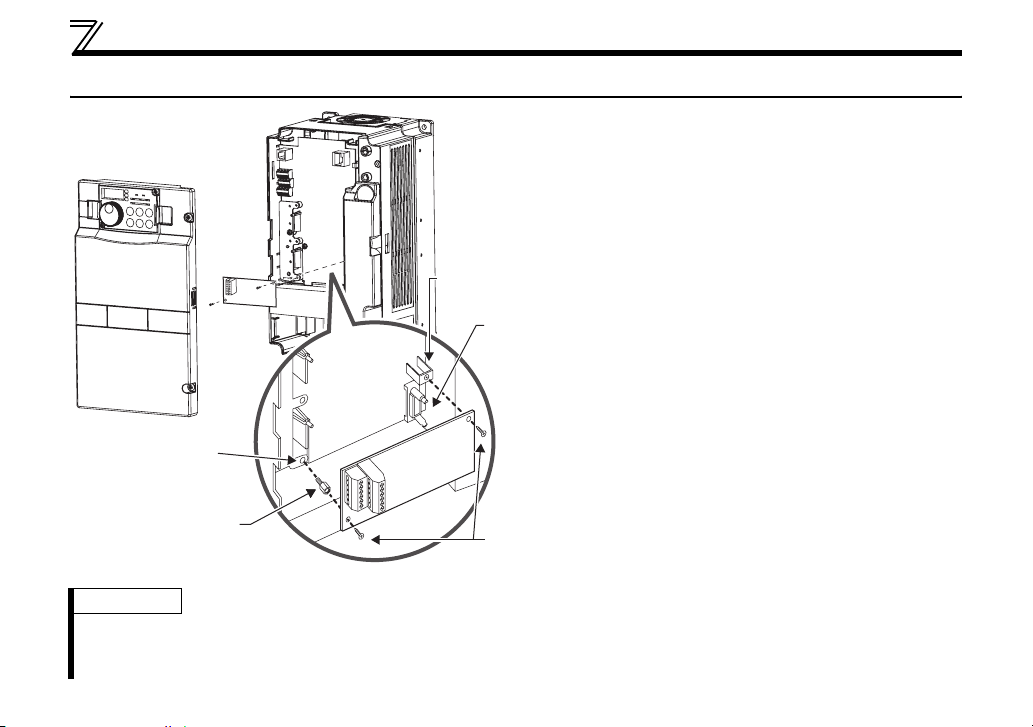
2.2 Installation procedure
1) Remove the inverter front cover.
1)
Screw hole for
option mounting
Inverter side
option
connector
3)
Screw hole for
option mounting
(on earth plate)
Hex-head screw
for option mounting
REMARKS
• Remove a plug-in option after removing two screws on both left and right sides.
(When the plug-in option is mounted in the connector 3), it is easier to remove the plug-in option after removing a
control circuit terminal block.)
2)
4) Mounting
screws
2) Mount the hex-head screw for option
mounting into the inverter screw hole
(on earth plate) (size 5.5mm, tightening
torque 0.56Nxm to 0.75Nxm).
3) Securely fit the connector of the plug-in
option to the inverter connector along
the guides.
4) Securely fix the both right and left sides
of the plug-in option to the inverter with
the accessory mounting screws.
(Tightening torque 0.33Nxm to
0.40Nxm)
If the screw holes do not line up, the
connector may not have been plugged
securely. Check for loose plugging.
5
Page 12
INSTALLATION
CAUTION
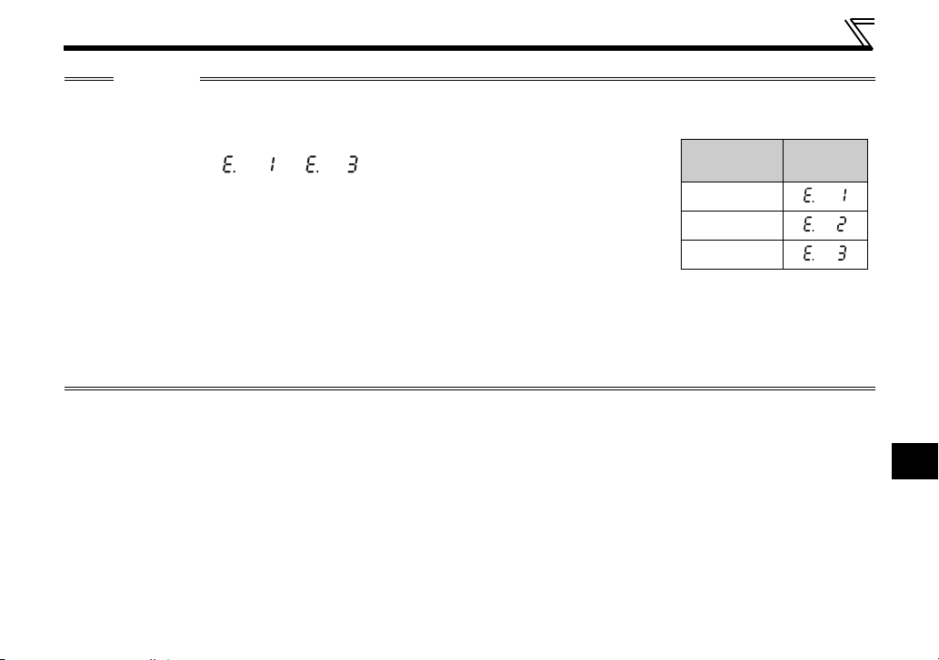
• Only one type of option per inverter may be used. When two or more options are mounted, priority is in the
order of inverter option connectors 1, 2 and 3. The options having lower priority are inoperative.
• When the inverter cannot recognize that the option is mounted due to improper
installation, etc., " to " (option fault) are displayed. The errors
shown differ according to the mounting positions (connectors 1, 2, 3).
• When mounting/removing an option, hold the sides of the option. Do not press
on the parts on the option circuit board. Stress applied to the parts by pressing, etc. may cause a failure.
• Take caution not to drop a hex-head screw for option mounting or mounting screw during mounting and
removal.
• Pull the option straight out when removing. Pressure applied to the connector and to the option circuit
board may break the option.
Mounting
Position
Connector 1
Connector 2
Connector 3
Error
Display
2
6
Page 13
INSTALLATION
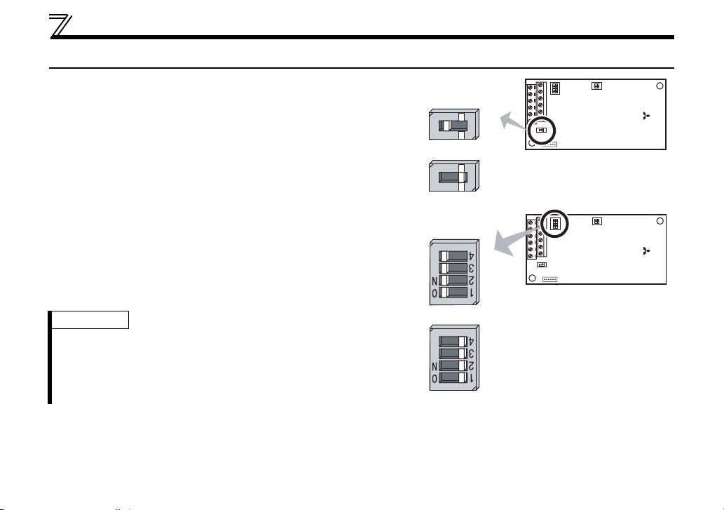
2.3 Encoder Specifications/Terminating Resistor Switch
4
(1) Encoder specification selection switch (SW1)
Select either differential line driver or complementary
It is initially set to the differential line driver. Switch its position
according to output circuit.
Differential line
driver (initial status)
Complementary
SW2
3
2
N
1
O
SW1
2
N
1
O
SW3
FR-A7AP
(2) Terminating resistor selection switch (SW2)
Select ON/OFF of the internal terminating resistor. Set the
switch to ON (initial status) when an encoder output type is
differential line driver and set to OFF when complementary.
ON : with internal terminating resistor (initial setting status)
OFF : without internal terminating resistor
REMARKS
· Set all switches to the same setting (ON/OFF).
· If the encoder output type is differential line driver, set the
terminating resistor switch to the "OFF" position when sharing the
same encoder with other unit (CNC (computerized numerical
controller), etc) or a terminating resistor is connected to other unit.
7
Internal terminating
resistor-ON
(initial status)
4
SW2
3
2
N
1
O
SW1
Internal terminating resistor-OFF
2
N
1
O
SW3
FR-A7AP
Page 14
INSTALLATION
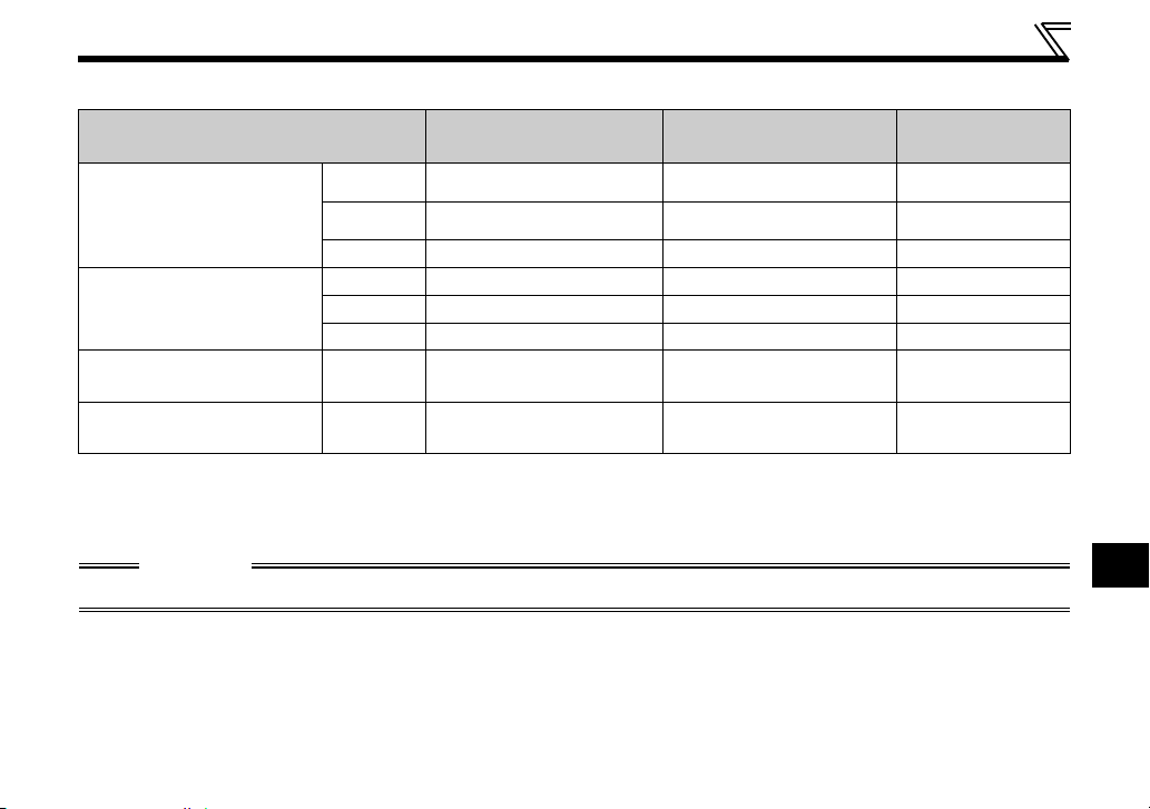
(3) Motor used and switch setting
Motor
Mitsubishi standard motor
with encoder
Mitsubishi high-efficiency
motor with encoder
Mitsubishi constant-torque
motor with encoder
Vector control dedicated
motor
Other manufacturer's
motor with encoder
*1 Set according to the motor encoder used.
*2 Choose a power supply for encoder according to the encoder used (5V/12V/15V/24V).When the encoder output
is the differential line driver type, only 5V can be input.
SF-JR Differential ON 5V
SF-HR Differential ON 5V
Others
SF-JRCA Differential ON 5V
SF-HRCA Differential ON 5V
Others
SF-V5RU Complementary OFF 12V
–
Encoder Specification
Selection Switch (SW1)
*1 *1 *1
*1 *1 *1
*1 *1 *1
Terminating Resistor
Selection Switch (SW2)
Power
Specifications
*2
CAUTION
Switch "SW3" is for manufacturer setting. Do not change the setting.
2
8
Page 15
INSTALLATION
r
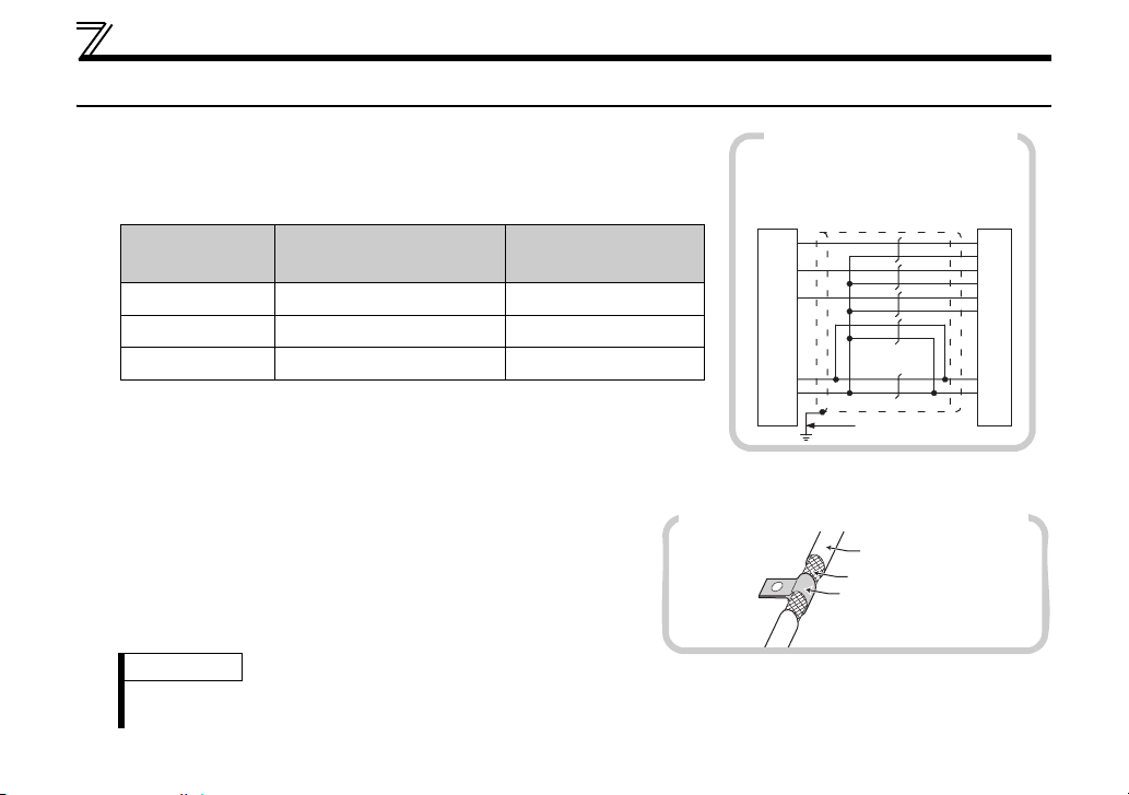
2.4 Wiring
(1) Use twisted pair shield cables (0.2mm2 or larger) to connect the FR-
A7AP and position detector.
To protect the cables from noise, run them away from any
source of noise (e.g. the main circuit and power voltage).
Wiring Length
Within 10m At least 2 cables
Within 20m At least 4 cables
Within 100m * At least 6 cables
* When differential driver is set and a wiring length is 30m or more
The wiring length can be extended to 100m by slightly increasing the power by
5V (approx. 5.5V) using six or more cables with gauge size of 0.2mm
parallel or a cable with gauge size of 1.25mm
applied should be within power supply specifications of encoder.
Parallel Connection
(Cable gauge 0.2mm
Larger-Size Cable
2
)
2
0.4mm
0.75mm
1.25mm
2
or more. Note that the voltage
or larger
2
or larger
2
or larger
2
in
To reduce noise of the encoder cable, earth (ground) the
Earthing (grounding) example using a P clip
Example of parallel connection
(with complementary encoder output)
FR-A700
(FR-A7AP)
PA1
PA2
PB1
PB2
PZ1
PZ2
encoder shielded cable to the enclosure (as close as the
inverter) with a P clip or U clip made of metal.
REMARKS
· For details of the optional encoder dedicated cable (FR-JCBL/FR-V7CBL), refer to page 13.
· FR-V7CBL is provided with a P clip for earthing (grounding) shielded cable.
PG
SD
with two cables
2
2mm
Encoder cable
Shield
P clip
Encode
A
B
C
D
F
G
S
R
9
Page 16

INSTALLATION
r
(2) Connection with the CNC (computerized numerical controller)
When one position detector is shared between FR-A7AP and
Inverter
(FR-A7AP)
Position detecto
NC, its output signal should be connected as shown on the right.
In this case, the wiring length between FR-A7AP and NC should
be as short as possible, within 5m.
Maximum 5m
(two parallel cables)
(3) Wire the shielded twisted pair cable after stripping its sheath to make
its cables loose.
Also, protect the shielded cable of the shielded twisted pair cable to
(perform protective treatment)
Sheath
Shield
ensure that it will not make contact with the conductive area.
Twisted pair
shielded cable
Strip off the sheath for the below length. If the length of the sheath peeled is too long, a short circuit
may occur with neighboring wires. If the length is too short, wires might come off.
Wire the stripped cable after twisting it to prevent it from becoming loose. In addition, do not solder it
Cable stripping length
(0.2 inches)5mm
Use a blade terminal as necessary.
Encoder
CNC
2
10
Page 17

INSTALLATION
REMARKS
Information on blade terminals
Introduced products (as of Feb. 2012)
zPhoenix Contact Co.,Ltd.
Terminal Screw
Size
Wire Size
2
(mm
)
with insulation sleeve without insulation sleeve
M2 0.3, 0.5 AI 0,5-6WH A 0,5-6
Blade Terminal Model
Blade terminal
crimping tool
CRIMPFOX 6
When using the blade terminal (without insulation
sleeve), use care so that the twisted wires do not come
(4) Loosen the terminal screw and insert the cable into the terminal.
Screw Size Tightening Torque Cable Size Screwdriver
M2 0.22N⋅m to 0.25N⋅m
0.3mm
2
to 0.75mm
2
Small flat-blade screwdriver
(Tip thickness: 0.4mm/tip width: 2.5mm )
CAUTION
Undertightening can cause cable disconnection or malfunction. Overtightening can cause a short circuit or
malfunction due to damage to the screw or unit.
11
Page 18

INSTALLATION
C
(5) For wiring of the inverter which has one front cover, remove a hook of the front cover and use a space
become available.
For wiring of the inverter which has front covers 1 and 2, use the space on the left side of the control
circuit terminal block.
Cut off
with a
nipper,
etc.
Front cover
Cut off a hook on the inverter
front cover side surface.
(Cut off so that no portion is left.)
Front cover 1
Front cover 2
Control circuit
terminal block
Inverter which has one front cover Inverter which has front covers 1 and 2
REMARKS
When the hook of the inverter front cover is cut off for wiring, the protective structure (JEM1030) changes to open type
(IP00).
AUTION
Do not use empty terminals as junction terminals because they are used in the option unit. If
they are used as the junction terminals, the option unit may be damaged.
When performing wiring using the space between the inverter front cover and control circuit
terminal block, take care not to subject the cable to stress.
After wiring, wire offcuts must not be left in the inverter. They may cause a fault, failure or
malfunction.
2
12
Page 19

INSTALLATION
2.5 Encoder Cable
SF-JR/HR/JRCA/HRCA Motor with Encoder SF-V5RU, SF-THY
2mm
L
2
Encoder side
connector
2
Encoder
A
B
C
D
F
G
S
R
D/MS3057-12A
D/MS3106B20-29S
Type Length L (m)
FR-V7CBL5 5
FR-V7CBL15 15
FR-V7CBL30 30
Positioning keyway
A
M
B
N
C
L
K
As viewed from wiring side
D
P
T
E
S
R
J
F
H
G
D/MS3106B20-29S
*
FR-A700
(FR-A7AP)
Earth cable
60mm
PA1
PA2
PB1
PB2
PZ1
PZ2
PG
SD
F-DPEVSB 12P 0.2mm
Approx. 140mm
L
Encoder
C
R
A
N
B
P
H
K
2
2mm
2
D/MS3057-12A
D/MS3106B20-29S
Type Length L (m)
FR-JCBL5 5
FR-JCBL15 15
FR-JCBL30 30
Positioning keyway
A
B
M
C
N
L
K
(As viewed from wiring side)
D
P
T
E
S
R
J
F
H
G
D/MS3106B20-29S
Inverter side
Earth cable
F-DPEVSB 12P 0.2mm
60mm
11m m
⋅ A P clip for earthing (grounding)
a shielded cable is provided.
FR-A700
(FR-A7AP)
PA1
PA2
PB1
PB2
PZ1
PZ2
PG
SD
* As the terminal block of the FR-A7AP is an insertion type, earth (ground) cables need to be modified. (Refer to page 11.)
13
Page 20

Connection terminal compatibility table
Motor SF-V5RU, SF-THY SF-JR/HR/JRCA/HRCA (with Encoder)
Encoder cable FR-V7CBL/FR-V5CBL FR-JCBL
PA1 PA PA
PA2 Keep this open. PAR
PB1 PB PB
FR-A7AP terminal
PB2 Keep this open. PBR
PZ1 PZ PZ
PZ2 Keep this open. PZR
PG PG 5E
SD SD AG2
INSTALLATION
2
14
Page 21

INSTALLATION
2.6 Encoder
(1) Position detection (pulse encoder)
Output pulse specifications
Differential line driver Complementary
A/A signal 1000P/R to 4096P/R
B/B signal 1000P/R to 4096P/R
Z/Z signal 1P/R
A
A
B
B
Z
Z
P
abcd
H
L
CAUTION
⋅ When orientation control, encoder feedback control, vector control are used together, the encoder is shared
between these controls.
Use an encoder which has a pulse count of 1000 to 4096ppr (pulse per revolution).
⋅
The encoder should be coupled with the motor shaft or the spindle oriented with a speed ratio of 1 to 1 without any
mechanical looseness.
⋅ To ensure correct operation, the encoder must be set in the proper rotation direction and the A and B phases
connected correctly.
A signal 1000P/R to 4096P/R
B signal 1000P/R to 4096P/R
Z signal 1P/R
P
abcd
A
B
Z
Position detector
Encoder
A
When rotation is clockwise
as viewed from the shaft
end (A) of the encoder.
a, b, c, d should be (1/4
1/8)P
15
Page 22

INSTALLATION
(2) Power supply
Choose a power supply for encoder according to the encoder used (5V/12V/15V/24V). When the encoder
output is the differential line driver type, only 5V can be input. Make sure the voltage of the external power
supply the same as the encoder output voltage. (Check the encoder specification.)
When an encoder is used under orientation control, encoder feedback control, and vector control, the power
supply is shared between the inverter and encoder.
⋅ Specifications of the encoders equipped in the motors with encoders and the vector-control dedicated
motors
Item Encoder for SF-JR/HR/JRCA/HRCA Encoder for SF-V5RU, SF-THY
Resolution 1024 pulses/rev 2048 pulses/rev
Power supply
voltage
Current
consumption
Output signal form
Output circuit Differential line driver 74LS113 equivalent Complementary
Output voltage
5VDC±10% 12VDC±10%
150mA 150mA
A, B phases (90° phase shift)
Z phase: 1 pulse/rev
H level: 2.4V or more
L level: 0.5V or less
A, B phases (90° phase shift)
Z phase: 1 pulse/rev
H level: "Power supply for encoder-3V" or more
L level: 3V or less
CAUTION
When the input power supply voltage to the encoder and its output voltage differ, the signal loss detection
(E.ECT) may occur.
2
16
Page 23

INSTALLATION
e
2.7 Parameter for Encoder
Parameter
Number
359
369
17
Name
Encoder rotation
direction
Number of encoder
pulses
Initial
Value
1024 0 to 4096
Setting
Range
0
1
1
Description
CW
Encoder
A
CCW
A
Encoder
Set the number of encoder pulses output.
Set the number of pulses before it is multiplied by 4.
Forward rotation is clockwise
rotation when viewed from A.
Forward rotation is counterclockwis
rotation when viewed from A.
Page 24

Parameter settings for the motor under vector control
Motor Name
SF-JR 1 1024
SF-JR 4P 1.5kW or
Mitsubishi standard motor
less
SF-HR 1 1024
Others
SF-JRCA 4P 1 1024
Mitsubishi constant-torque motor
SF-HRCA 1 1024
Others
Mitsubishi vector control dedicated
motor
SF-V5RU
series)
SF-THY 1 2048
(1500r/min
Other manufacturer's standard motor —
Other manufacturer's constant-torque
motor
Values in the bolded frame are initial values.
* Set this parameter according to the motor (encoder) used.
—
Encoder rotation direction
Pr. 359
1 1024
**
**
1 2048
**
**
INSTALLATION
Pr. 369
Number of encoder pulses
2
18
Page 25

3 ORIENTATION CONTROL
This function is used with a position detector (encoder) installed to the spindle of a machine tool, etc. to
allow a rotary shaft to be stopped at the specified position (oriented).
3.1 Wiring Example
MCCB
Three-phase
AC power
supply
Forward rotation start
Reverse rotation start
Orientation command
Contact input common
19
MC
Inverter
R/L1
S/L2
T/L3
STF
STR
X22*3
SD
ORA*4
ORM
*4
SE
SD
FR-A7AX
*10
X15
X14
X1
X0
DY
U
V
W
FR-A7AP
PA1
PA2
PB1
PB2
PZ1
PZ2
Differential
PG
SD
Complementary
PG
Terminating
SD
resistor ON
OFF
*8
*7
SF-JR motor with encoder
U
V
W
IM
E
Earth (Ground)
*2
C
R
A
N
Encoder
B
P
*5
H
K
*6
(-)
5VDC power
(+)
supply
*9
For complementary type (SF-V5RU)
MCCB
CS(OH)
*7
PC
SD
PA1
PA2
PB1
PB2
PZ1
PZ2
PG
SD
PG
SD
*8
W
U
V
MC OCR
U
V
W
E
Earth (Ground)
2W1kΩ
G1
G2
A
B
C
D
F
G
S
R
*6
(+)
*1
Three-phase
AC power
supply
Inverter
External
thermal relay
input
*11
FR-A7AP
Differential
Complementary
Terminating
resistor ON
OFF
SF-V5RU
Thermal
relay
protector
*2
Encoder
(-)
12VDC power
supply
FAN
IM
*5
*9
Page 26

ORIENTATION CONTROL
*1 For the fan of the 7.5kW or less dedicated motor, the power supply is single phase (200V/50Hz, 200 to 230V/
60Hz).
*2 The pin number differs according to the encoder used.
*3 Use Pr. 178 to Pr. 189 (input terminal function selection) to assign the function to any of terminal.
Refer to the inverter manual for details of Pr. 178 to Pr. 189 (input terminal function selection).
*4 Use Pr. 190 to Pr. 196 (output terminal function selection) to assign the function to any of terminal.
Refer to the inverter manual for details of Pr. 190 to Pr. 196 (output terminal function selection).
*5 Connect the encoder so that there is no looseness between the motor and motor shaft. Speed ratio should be 1:1.
*6 Earth (Ground) the shielded cable of the encoder cable to the enclosure with a P clip, etc. (Refer to page 9.)
*7 For the differential line driver, set the terminating resistor selection switch to on position (initial status) to use.
(Refer to page 7.)
Note that the terminating resistor switch should be set to off position when sharing the same encoder with other
unit (NC, etc.) or a terminating resistor is connected to other unit.
For the complementary, set the switch to off position.
*8 For terminal compatibility of the FR-JCBL, FR-V7CBL and FR-A7AP, refer to page 14.
*9 A separate power supply of 5V/12V/15V/24V is necessary according to the encoder power specification.When the
encoder output is the differential line driver type, only 5V can be input.
Make the voltage of the external power supply the same as the encoder output voltage, and connect the external
power supply between PG and SD.
When performing encoder feedback control and vector control together, an encoder and power can be shared.
*10 When a stop position command is input from outside, a plug-in option FR-
A7AX is necessary. Refer to the inverter manual for details of external
stop position command.
*11 Assign OH (external thermal input) signal to the terminal CS. (Set "7" in
Pr. 186 )
Connect a 2W1kΩ resistor between the terminal PC and CS.
Install the resistor pushing against the bottom part of the terminal block so
as to avoid a contact with other cables.
CS(OH)
PC
Control circuit
terminal block
Resistor (2W1kΩ)
3
20
Page 27

ORIENTATION CONTROL
3.2 Terminals
(1) Option FR-A7AP terminal
Termi nal
Symbol
PA1
PA2
PB1
PB2
PZ1
PZ2
PG
SD
Encoder A-phase signal input terminal
Encoder A-phase inverse signal input
terminal
Encoder B-phase signal input terminal
Encoder B-phase inverse signal input
terminal
Encoder Z-phase signal input terminal
Encoder Z-phase inverse signal input
terminal
Power supply (positive side) input
terminal
Power supply ground terminal
Terminal Name Description
A-, B- and Z-phase signals are input from the encoder.
(For details of pulse signal, refer to page 15.)
Input power for the encoder power supply.
Connect the external power supply (5V, 12V, 15V, 24V) and the
encoder power cable. When the encoder output is the differential
line driver type, only 5V can be input. Make sure the voltage of
the external power supply the same as the encoder output
voltage. (Check the encoder specification.)
21
Page 28

(2) Option FR-A7AX terminal
Termina l
Symbol
X0 to X15
DY
SD
(inverter)
PC
(inverter)
Terminal Name Description
Digital signal input
terminal
Data read timing
input signal terminal
Common terminal
(sink) terminal
External transistor
common terminal
(source)
ORIENTATION CONTROL
Input the digital signal at the relay contact or open collector terminal.
Using
Pr. 360
, speed or position command is selected as the command signal entered.
Used when a digital signal read timing signal is necessary. Data is read only
during the DY signal is on.
By switching the DY signal off, the X0 to X15 data before signal-off is retained.
Common terminal for digital and data read timing signals.
Use terminal SD of the inverter.
When connecting the transistor output (open collector output), such as a
programmable controller (PLC), connect the external power common (+) to this
terminal to prevent a fault occurring due to leakage current.
3
22
Page 29

ORIENTATION CONTROL
(3) Inverter terminal
Termina l
(Signal)
Input
Output
* Refer to the inverter manual for the details of Pr.178 to Pr.189 (input terminal function selection) and Pr.190 to Pr.196
(output terminal function selection).
Terminal (Signal) Name Application Explanation
Orientation command
X22
input terminal
Used to enter an orientation signal for orientation.
For the terminal used for X22 signal input, set "22" in any of Pr. 178 to Pr. 189
to assign the function. *
SD Contact input common Common terminal for the orientation signal.
Switched low if the orientation has stopped within the in-position zone while
In-position signal output
ORA
signal
Orientation fault signal
ORM
output signal
Open collector output
SE
common
the start and orientation signals are input.
For the terminal used for the ORA signal output, assign the function by
setting "27 (positive logic) or 127 (negative logic)" in any of Pr. 190 to Pr. 196. *
Switched low if the orientation has stopped within the in-position zone while
the start and orientation signals are input.
For the terminal used for the ORA signal output, assign the function by
setting "28 (positive logic) or 128 (negative logic)" in any of Pr. 190 to Pr. 196. *
Common terminal for the ORA and ORM open collector output terminals.
23
Page 30

ORIENTATION CONTROL
3.3 Parameter List for Orientation Control
Fitting the FR-A7AP adds the following parameters for orientation control.
Refer to the Inverter Manual (Applied) for details of parameter.
Parameter
Number
350 Stop position command selection 0, 1, 9999 1 9999
351 Orientation speed 0 to 30Hz 0.01Hz 2Hz
352 Creep speed 0 to 10Hz 0.01Hz 0.5Hz
353 Creep switchover position 0 to 16383
354 Position loop switchover position 0 to 8191 1 96
355 DC injection brake start position 0 to 255 1 5
356 Internal stop position command 0 to 16383
357 Orientation in-position zone 0 to 255 1 5
358 Servo torque selection 0 to 13 1 1
359 Encoder rotation direction 0, 1 1 1
360 16 bit data selection 0 to 127 1 0
361 Position shift 0 to 16383
362 Orientation position loop gain 0.1 to 100 0.1 1
363 Completion signal output delay time 0 to 5s 0.1s 0.5s
364 Encoder stop check time 0 to 5s 0.1s 0.5s
365 Orientation limit 0 to 60s, 9999 1s 9999
366 Recheck time 0 to 5s, 9999 0.1s 9999
369 Number of encoder pulses 0 to 4096 1 1024
376 Encoder signal loss detection enable/disable selection 0, 1 1 0
393 Orientation selection 0, 1, 2 1 0
396 Orientation speed gain (P term) 0 to 1000 1 60
397 Orientation speed integral time 0 to 20s 0.001 0.333
398 Orientation speed gain (D term) 0 to 100 0.1 1
399 Orientation deceleration ratio 0 to 1000 1 20
* When an operation panel (FR-DU07) is used, the maximum setting is 9999. When a parameter unit is used, up to the maximum value
within the setting range can be set.
Name Setting Range Increments Initial Value
* 1511
* 10
* 10
3
24
Page 31

ORIENTATION CONTROL
3.4 Specifications
Repeated positioning
accuracy
Permissible speed
Functions
Holding force after
positioning
Input signal (contact
input)
Output signal
(open collector output)
±1.5°
Depends on the load torque, moment of inertia of the load or orientaion, creep speed,
position loop switching position, etc.
Encoder-mounted shaft speed (6000r/min with 1024 pulse encoder)
The drive shaft and encoder-mounted shaft must be coupled directly or via a belt without any slip.
Orientation, creep speed setting, stop position command selection, DC injection brake start
position setting, creep speed and position loop switch position setting, position shift,
orientation in-position, position pulse monitor, etc.
Under V/F control, Advanced magnetic flux vector control...without servo lock function
Under vector control ....with servo lock function
Orientation command, forward and reverse rotation commands, stop position command
(open collector signal input (complementary) is enabled)
binary signal of maximum 16 bit (when used with the FR-A7AX)
Orientation completion signal, orientation fault signal
25
Page 32

MEMO
26
Page 33

4 ENCODER FEEDBACK CONTROL
A
Mount FR-A7AP to an FR-A700 series inverter to perform encoder feedback control under V/F control or
Advanced magnetic flux vector control.
This controls the inverter output frequency so that the motor speed is constant to the load variation by
detecting the motor speed with the speed detector (encoder) to feed back to the inverter.
4.1 Wiring Examples
MCCB
Three-phase
C power supply
Forward rotation start
Reverse rotation start
Contact input common
Frequency setting
potentiometer
MC
R/L1
S/L2
T/L3
STF
STR
SD
10
2
5
Inverter
FR-A7AP
Differential
Complementary
Terminating
resistor ON
*4
OFF
U
V
W
PA1
PA2
PB1
PB2
PG
SD
PG
SD
*5
SF-JR motor with encoder
U
V
W
E
Earth
(Ground)
C
R
A
N
H
K
*3
(+)
IM
*1
Encoder
*2
(-)
5VDC power supply *6
27
Page 34

ENCODER FEEDBACK CONTROL
*1 The pin number differs according to the encoder used.
*2 Connect the encoder so that there is no looseness between the motor and motor shaft. Speed ratio should be 1:1.
*3 Earth (Ground) the shielded cable of the encoder cable to the enclosure with a P clip, etc. (Refer to page 9.)
*4 For the differential line driver, set the terminating resistor selection switch to on position (initial status) to use.
(Refer to page 7) Note that the terminating resistor switch should be set to off position when sharing the same
encoder with other unit (NC, etc) or a terminating resistor is connected to other unit.
For the complementary, set the switch to off position.
*5 For terminal compatibility of the FR-JCBL, FR-V7CBL and FR-A7AP, refer to page 14.
*6 A separate power supply of 5V/12V/15V/24V is necessary according to the encoder power specification.When the
encoder output is the differential line driver type, only 5V can be input.
Make the voltage of the external power supply the same as the encoder output voltage, and connect the external
power supply between PG and SD.
To perform orientation control together, an encoder and power supply can be shared.
28
4
Page 35

ENCODER FEEDBACK CONTROL
4.2 Terminals
Termi nal
Symbol
PA1
PA2
PB1
PB2
PG
SD
Termin a l N a m e Description
Encoder A-phase signal
input terminal
Encoder A-phase inverse
signal input terminal
Encoder B-phase signal
input terminal
Encoder B-phase inverse
signal input terminal
Power supply (positive
side) input terminal
Power ground terminal
A-, B-phase signals are input from the encoder.
(For details of pulse signal, refer to page 15.)
Input power for the encoder power supply.
Connect the external power supply (5V, 12V, 15V, 24V) and the encoder
power cable. When the encoder output is the differential line driver type,
only 5V can be input. Make sure the voltage of the external power supply
the same as the encoder output voltage. (Check the encoder specification.)
29
Page 36

ENCODER FEEDBACK CONTROL
4.3 Encoder Feedback Control Parameter List
Fitting the FR-A7AP adds the following parameters for encoder feedback operation.
Refer to the Inverter Manual (Applied) for details of parameter.
Parameter
Number
359 Encoder rotation direction 0, 1 1 1
367 Speed feedback range 0 to 400Hz, 9999 0.01Hz 9999
368 Feedback gain 0 to 100 0.1 1
369 Number of encoder pulses 0 to 4096 1 1024
374 Overspeed detection level 0 to 400Hz 0.01Hz 140Hz
376
Encoder signal loss detection
enable/disable selection
Name Setting Range Increments Initial Value
0, 1 1 0
4.4 Specifications
Speed variation ratio
Function
Maximum speed 120Hz (102400 pulse/s or less encoder pulses)
±0.1% (100% means 3600r/min)
⋅ Setting of speed feedback range
⋅ Setting of feedback gain
⋅ Setting of encoder rotation direction
4
30
Page 37

5 VECTOR CONTROL
A
When FR-A7AP is mounterd on the FR-A700 series, full-scale vector control operation can be performed
using a motor with encoder.
Speed control, torque control and position control by vector control can be performed. (Refer to the Inverter
Manual (Applied) for details.)
5.1 Wiring Examples
(1) Standard motor with encoder, 5V differential line driver (speed control)
MCCB
Three-phase
C power supply
Frequency command
Frequency setting
Forward rotation start
Reverse rotation start
Contact input common
potentiometer
1/2W1k
Torque limit
command
( 10V)
(+)
(-)
3
Ω
1
MC
2
R/L1
S/L2
T/L3
STF
STR
SD
10
2
5
1
Inverter
FR-A7AP
Differential
Complementary
Terminating
resistor ON
OFF
*4
U
V
W
PA1
PA2
PB1
PB2
PZ1
PZ2
PG
SD
PG
SD
*6
SF-JR motor with encoder
U
Earth
(Ground)
*3
(+)
V
W
E
C
R
A
N
B
P
H
K
(-)
IM
*1
Encoder
*2
5VDC power supply *5
31
Page 38

VECTOR CONTROL
*1 The pin number differs according to the encoder used.
Speed and torque controls are available with or without the Z-phase being connected.
*2 Connect the encoder so that there is no looseness between the motor and motor shaft. Speed ratio should be 1:1.
*3 Earth (Ground) the shielded cable of the encoder cable to the enclosure with a P clip, etc. (Refer to page 9.)
*4 For the differential line driver, set the terminating resistor selection switch to on position (initial status) to use.
(Refer to page 7)
Note that the terminating resistor switch should be set to off position when sharing the same encoder with other
unit (NC, etc) or a terminating resistor is connected to other unit.
*5 A separate power supply of 5V/12V/15V/24V is necessary according to the encoder power specification. When
the encoder output is the differential line driver type, only 5V can be input.
Make the voltage of the external power supply the same as the encoder output voltage, and connect the external
power supply between PG and SD.
To perform orientation control together, an encoder and power supply can be shared.
*6 For terminal compatibility of the FR-JCBL, FR-V7CBL and FR-A7AP, refer to page 14.
32
5
Page 39

VECTOR CONTROL
(2) Vector control dedicated motor (SF-V5RU), 12V complementary (torque control)
AC power supply
Forward rotation start
Reverse rotation start
Contact input common
Speed limit command
Frequency setting
potentiometer
1/2W1k
Torque command
( 10V)
(+)
(-)
Three-phase
3
2
Ω
1
Three-phase
*7
AC power supply
MCCB
R/L1
S/L2
T/L3
STF
STR
SD
10
2
5
1
MCCB
Inverter
External
CS(OH)
thermal
relay input
FR-A7AP
Differential
Complementary
Terminating
resistor
ON
OFF
*4
*8
PC
SD
PA1
PA2
PB1
PB2
PZ1
PZ2
PG
SD
PG
SD
*6
MC OCR
U
V
W
2W1k
A
B
C
U
V
W
E
Earth (Ground)
G1
Ω
G2
A
B
C
D
F
G
S
R
*3
12VDC
(-)
(+)
power supply
SF-V5RU
FAN
IM
Thermal relay
protector
*1
Encoder
*2
*5
33
Page 40

VECTOR CONTROL
*1 The pin number differs according to the encoder used.
Speed and torque controls are available with or without the Z-phase being connected.
*2 Connect the encoder so that there is no looseness between the motor and motor shaft. Speed ratio should be 1:1.
*3 Earth (Ground) the shielded cable of the encoder cable to the enclosure with a P clip, etc. (Refer to page 9.)
*4 For the complementary, set the terminating resistor selection switch to off position. (Refer to page 7.)
*5 A separate power supply of 5V/12V/15V/24V is necessary according to the encoder power specification. When
the encoder output is the differential line driver type, only 5V can be input.
Make the voltage of the external power supply the same as the encoder output voltage, and connect the external
power supply between PG and SD.
When performing orientation control together, an encoder and power supply can be shared.
*6 For terminal compatibility of the FR-JCBL, FR-V7CBL and FR-A7AP, refer to page 14.
*7 For the fan of the 7.5kW or less dedicated motor, the power supply is single phase. (200V/50Hz, 200 to 230V/
60Hz)
*8 Assign OH (external thermal input) signal to the terminal CS. (Set "7" in
Pr. 186 )
Connect a 2W1kΩ resistor between the terminal PC and CS (OH). Install
the resistor pushing against the bottom part of the terminal block so as to
avoid a contact with other cables.
CS(OH)
PC
Control circuit
terminal block
Resistor (2W1kΩ)
34
5
Page 41

VECTOR CONTROL
5.2 Terminals
Termi nal
Symbol
PA1
PA2
PB1
PB2
PZ1
PZ2
PG
SD
Terminal Name Description
Encoder A-phase signal input terminal
Encoder A-phase inverse signal input
terminal
Encoder B-phase signal input terminal
Encoder B-phase inverse signal input
terminal
Encoder Z-phase signal input terminal
Encoder Z-phase inversion signal input
terminal
Encoder power supply (positive side)
input terminal
Encoder power supply ground terminal
A-, B- and Z-phase signals are input from the encoder.
(For details of pulse signal, refer to page 15.)
Input power for the encoder power supply.
Connect the external power supply (5V, 12V, 15V, 24V) and the
encoder power cable. When the encoder output is the
differential line driver type, only 5V can be input. Make sure the
voltage of the external power supply the same as the encoder
output voltage. (Check the encoder specification.
35
Page 42

VECTOR CONTROL
5.3 Vector Control Extended Parameter List
Mounting FR-A7AP adds the following parameters for vector control.
Refer to the Inverter Manual (Applied) for details of parameter.
Parameter
Number
359 Encoder rotation direction 0, 1 1 1
369 Number of encoder pulses 0 to 4096 1 1024
374 Overspeed detection level 0 to 400Hz 0.01Hz 140Hz
376
419 Position command source selection 0, 2 1 0
420 Command pulse scaling factor numerator 0 to 32767 * 1 1
421 Command pulse scaling factor denominator 0 to 32767 * 1 1
422 Position loop gain
423 Position feed forward gain 0 to 100% 1% 0
424
425 Position feed forward command filter 0 to 5s 0.001s 0s
426 In-position width 0 to 32767pulses * 1 100
427 Excessive level error 0 to 400K, 9999 1K 40K
428 Command pulse selection 0 to 5 1 0
429 Clear signal selectionClear signal selection 0, 1 1 1
430 Pulse monitor selection 0 to 5, 9999 1 9999
464
* When an operation panel (FR-DU07) is used, the maximum setting is 9999. When a parameter unit is used, up to the maximum value
within the setting range can be set.
Encoder signal loss detection enable/disable selection
Position command acceleration/deceleration time
constant
Digital position control sudden stop deceleration time
Name Setting Range Increments Initial Value
0, 1 1 0
0 to 150sec
0 to 50s 0.001s 0s
0 to 360.0s 0.1s 0
-1
1sec
-1
25sec
-1
36
5
Page 43

VECTOR CONTROL
Parameter
Number
465 First position feed amount lower 4 digits 0 to 9999 1 0
466 First position feed amount upper 4 digits 0 to 9999 1 0
467 Second position feed amount lower 4 digits 0 to 9999 1 0
468 Second position feed amount upper 4 digits 0 to 9999 1 0
469 Third position feed amount lower 4 digits 0 to 9999 1 0
470 Third position feed amount upper 4 digits 0 to 9999 1 0
471 Fourth position feed amount lower 4 digits 0 to 9999 1 0
472 Fourth position feed amount upper 4 digits 0 to 9999 1 0
473 Fifth position feed amount lower 4 digits 0 to 9999 1 0
474 Fifth position feed amount upper 4 digits 0 to 9999 1 0
475 Sixth position feed amount lower 4 digits 0 to 9999 1 0
476 Sixth position feed amount upper 4 digits 0 to 9999 1 0
477 Seventh position feed amount lower 4 digits 0 to 9999 1 0
478 Seventh position feed amount upper 4 digits 0 to 9999 1 0
479 Eighth position feed amount lower 4 digits 0 to 9999 1 0
480 Eighth position feed amount upper 4 digits 0 to 9999 1 0
481 Ninth position feed amount lower 4 digits 0 to 9999 1 0
482 Ninth position feed amount upper 4 digits 0 to 9999 1 0
483 Tenth position feed amount lower 4 digits 0 to 9999 1 0
484 Tenth position feed amount upper 4 digits 0 to 9999 1 0
485 Eleventh position feed amount lower 4 digits 0 to 9999 1 0
486 Eleventh position feed amount upper 4 digits 0 to 9999 1 0
487 Twelfth position feed amount lower 4 digits 0 to 9999 1 0
Name Setting Range Increments Initial Value
37
Page 44

VECTOR CONTROL
Parameter
Number
488 Twelfth position feed amount upper 4 digits 0 to 9999 1 0
489 Thirteenth position feed amount lower 4 digits 0 to 9999 1 0
490 Thirteenth position feed amount upper 4 digits 0 to 9999 1 0
491 Fourteenth position feed amount lower 4 digits 0 to 9999 1 0
492 Fourteenth position feed amount upper 4 digits 0 to 9999 1 0
493 Fifteenth position feed amount lower 4 digits 0 to 9999 1 0
494 Fifteenth position feed amount upper 4 digits 0 to 9999 1 0
802 Pre-excitation selection 0, 1 1 0
823 Speed detection filter 1 0 to 0.1s 0.001s 0.001s
833 Speed detection filter 2 0 to 0.1s, 9999 0.001s 9999
840 Torque bias selection 0 to 3, 9999 1 9999
841 Torque bias 1 600 to 1400%, 9999 1% 9999
842 Torque bias 2 600 to 1400%, 9999 1% 9999
843 Torque bias 3 600 to 1400%, 9999 1% 9999
844 Torque bias filter 0 to 5s, 9999 0.001s 9999
845 Torque bias operation time 0 to 5s, 9999 0.01s 9999
846 Torque bias balance compensation 0 to 10V, 9999 0.1V 9999
847 Fall-time torque bias terminal 1 bias 0 to 400%, 9999 1% 9999
848 Fall-time torque bias terminal 1 gain 0 to 400%, 9999 1% 9999
853 Speed deviation time 0 to 100s 0.1s 1s
873 Speed limit 0 to 120Hz 0.01Hz 20Hz
Name Setting Range Increments Initial Value
38
5
Page 45

VECTOR CONTROL
5.4 Specifications
Speed control range 1:1500 (both driving/regeneration *1)
Speed variation ratio ±0.01% (100% means 3000r/min)
Speed control
Torque control
Function
*1 Regeneration unit (option) is necessary for regeneration
*2 With online auto tuning (adaptive magnetic flux observer), dedicated motor, rated load
Speed response
Maximum speed 120Hz (102400 pulse/s or less encoder pulses)
Torque control range 1:50
Absolute torque accuracy ±10% *2
Repeated torque accuracy ±5% *2
300rad/s Note that the internal response is 600rad/s (with model
adaptive speed control)
⋅ Setting of speed feedback range
⋅ Setting of feedback gain
⋅ Setting of encoder rotation direction
IB(NA)-0600238ENG-C
39
Page 46

REVISIONS
*The manual number is given on the bottom left of the back cover.
Print Date *Manual Number Revision
Sep. 2005 IB(NA)-0600238ENG-A First edition
Addition
⋅ Radio Waves Act (South Korea)
⋅ Screw tightening torque of the built-in option
Aug. 2011 IB(NA)-0600238ENG-B
⋅ Encoder feedback control specification
Modification
⋅ Permissible speed under orientation control
⋅ Maximum speed under vector control
Addition
Sep. 2012 IB(NA)-0600238ENG-C
⋅ Note on the differential line driver type encoder
Deletion
⋅ Radio Waves Act (South Korea)
40
Page 47

INVERTER
HEAD OFFICE: TOKYO BUILDING 2-7-3, MARUNOUCHI, CHIYODA-KU, TOKYO 100-8310, JAPAN
Printed in Japan Specifications subject to change without notice.IB(NA)-0600238ENG-C (1209) MEE
 Loading...