

Mitsubishi Electric FR-A760-00017-NA, FR-A760-00061-NA, FR-A760-00120-NA, FR-A760-00220-NA, FR-A760-00330-NA Installation Manual
...
INVERTER
FR-A700
INSTALLATION GUIDELINE
FR-A760-00017 to 00840-NA
Thank you for choosing this Mitsubishi Inverter.
Please read through this Installation Guideline and a CD-ROM enclosed to operate this inverter correctly.
Do not use this product until you have a full knowledge of the equipment, safety information and
instructions.
Please forward this Installation Guideline and the CD-ROM to the end user.
CONTENTS
INSTALLATION OF THE INVERTER AND INSTRUCTIONS................. 1
1
OUTLINE DIMENSION DRAWING ......................................................... 2
2
WIRING .................................................................................................... 3
3
PRECAUTIONS FOR USE OF THE INVERTER................................... 11
4
PARAMETER LIST................................................................................ 13
5
TROUBLESHOOTING........................................................................... 21
6
700
This section is specifically about safety matters
Do not attempt to install, operate, maintain or inspect the inverter until you
have read through this Installation Guideline and appended documents
carefully and can use the equipment correctly. Do not use the inverter until
you have a full knowledge of the equipment, safety information and
instructions. In this Installation Guideline, the safety instruction levels are
classified into "WARNING" and "CAUTION".
WARNING
CAUTION
Note that even the level may lead to a serious consequence
according to conditions. Please follow strictly the instructions of both levels
because they are important to personnel safety.
1. Electric Shock Prevention
• While power is on or when the inverter is running, do not open the front cover.
Otherwise you may get an electric shock.
• Do not run the inverter with the front cover or wiring cover removed.
Otherwise, you may access the exposed high-voltage terminals or the charging
part of the circuitry and get an electric shock.
•
Even if power is off, do not remove the fron t cover except for w iring or periodic
inspection.You may access the charged inv erter circuits and get an electric shock.
• Before starting wiring or inspection, check to make sure that the operation panel
indicator is off, wait for at least 10 minutes after the power supply has been
switched off, and check that there are no residual voltage using a tester or the
like. The capacitor is charged with high voltage for some time after power off and
it is dangerous.
• This inverter must be earthed
the requirements of national and local safety regulations and electrical codes.
(NEC section 250, IEC 536 class 1 and other applicable standards)
• Any person who is involved in the wiring or inspection of this equipment should
be fully competent to do the work.
• Always install the inverter before wiring. Otherwise, you may get an electric shock
or be injured.
• Perform setting dial and key operations with dry hands to prevent an electric
shock. Otherwise you may get an electric shock.
• Do not subject the cables to scratches, excessive stress, heavy loads or
pinching. Otherwise you may get an electric shock.
• Do not replace the cooling fan while power is on. It is dangerous to replace the
cooling fan while power is on.
•
Do not touch the printed circuit board with wet hands. You may get an electric shock.
2. Fire Prevention
• Install the inverter on an incombustible wall without holes, etc.
Mounting it to or near combustible material can cause a fire.
• If the inverter has become faulty, switch off the inverter power.
A continuous flow of large current could cause a fire.
• When using a brake resistor, make up a sequence that will turn off power when
an alarm signal is output.
Otherwise, the brake resistor may excessively overheat due to damage of the
brake transistor and such, causing a fire.
•
Do not connect a resistor directly to the DC terminals P/+, N/−. This could cause a fire.
3. Injury Prevention
• Apply only the voltage specified in the instruction manual to each terminal.
Otherwise, burst, damage, etc. may occur.
• Ensure that the cables are connected to the correct terminals. Otherwise, burst,
damage, etc. may occur.
• Always make sure that polarity is correct to prevent damage, etc. Otherwise,
burst, damage, etc. may occur.
• While power is on or for some time after power-off, do not touch the inverter as it
is hot and you may get burnt.
4. Additional Instructions
Also note the following points to prevent an accidental failure, injury, electric
shock, etc.
(1) Transportation and installation
• When carrying products, use correct lifting gear to prevent injury.
• Do not stack the inverter boxes higher than the number recommended.
• Ensure that installation position and material can withstand the weight of the
inverter. Install according to the information in the instruction manual.
• Do not ins tall or ope rate the inverter if it is damag ed or has pa rts missi ng. This ca n
result in br eakdowns.
• When carrying the inverter, do not hold it by the front cover or setting dial; it may
fall off or fail.
• Do not stand or rest heavy objects on the product.
• Check the inverter mounting orientation is correct.
• Prevent other conductive bodies such as screws and metal fragments or other
flammable substance such as oil from entering the inverter.
• As the inverter is a precision instrument, do not drop or subject it to impact.
• Use the inverter under the following environmental conditions. Otherwise, the
inverter may be damaged.
Ambient
temperatur e
Ambient
humidity
Storage
temperatur e
Atmosphere
Environment
Altitude,
vibration
*1 Temperature applicable for a short time, e.g. in transit.
Assumes that incorrect handling may cause hazardous
conditions, resulting in death or severe injury.
Assumes that incorrect handling may cause
hazardous conditions, resulting in medium or slight
injury, or may cause physical damage only.
CAUTION
WARNING
(grounded). Earthing (Grounding) must conform to
CAUTION
CAUTION
CAUTION
-10°C to +40°C (14°F to 104°F)(non-freezing)
SLD of 00061 or less : -10° C to +30°C (14°F to 86°F)(no n-freezin g)
90% RH or les s (non-conde nsing)
-20°C to +65°C
Indoors (free from corrosive gas, flammable gas, oil mist, dust and
dirt)
Maximum 1000m (3280.80feet) above sea level for standard operation. After
that derate by 3% for every extra 500m (1640.40feet) up to 2500m (8202feet)
(92%) 5.9m/s
*1 (-4°F to 149°F)
2
or less
(2) Wiring
• Do not install a power factor correction capacitor or surge suppressor/radio
noise filter (capacitor type filter) on the inverter output side.
• The connection orientation of the output cables U, V, W to the motor will affect
the direction of rotation of the motor.
CAUTION
(3) Test operation and adjustment
• Before starting operation, confirm and adjust the parameters. A failure to do so
may cause some machines to make unexpected motions.
(4) Operation
• When you have chosen the retry function, stay away from the equipment as it
will restart suddenly after an alarm stop.
• Since the key is valid only when functions are set (refer to the Instruction
Manual (applied) ), provide a circuit and switch separately to make an emergency
stop (power off, mechanical brake operation for emergency stop, etc).
• Make sure that the start signal is off before resetting the inverter alarm. A failure
to do so may restart the motor suddenly.
• The load used should be a three-phase induction motor only. Connection of any
other electrical equipment to the inverter output may damage the inverter as well as
equipment.
• Performing pre-excitation (LX signal and X13 signal) under torque control (real
sensorless vector control) may start the motor running at a low speed even
when the start command (STF or STR) is not input. The motor may run also at a
low speed when the speed limit value = 0 with a start command i nput. Perform
pre-excitation after making sure that there will be no problem in safety if the
motor runs.
• Do not modify the equipment.
• Do not perform parts removal which is not instructed in manuals. Doing so may
lead to fault or damage of the inverter.
• The electronic thermal relay function does not guarantee protection of the motor
from overheating.
• Do not use a magnetic contactor on the inverter input for frequent starting/
stopping of the inverter.
• Use a noise filter to reduce the effect of electromagnetic interference. Otherwise
nearby electronic equipment may be affected.
• Take measures to suppress harmonics. Otherwise power supply harmonics from
the inverter may heat/damage the power factor correction capacitor and
generator.
• When a 575V class motor is inverter-driven, it should be insulation-enhanced or
surge voltages suppressed. Surge voltages attributable to the wiring constants
may occur at the motor terminals, deteriorating the insulation of the motor.
• When parameter clear or all clear is performed, reset the required parameters
before starting operations. Each parameter returns to the initial value.
• The inverter can be easily set for high-speed operation. Before changing its
setting, fully examine the performances of the motor and machine.
• In addition to the inverter's holding function, install a holding device to ensure
safety.
• Before running an inverter which had been stored for a long period, always
perform inspection and test operation.
• For prevention of damage due to static electricity, touch nearby metal before
touching this product to eliminate static electricity from your body.
(5) Emergency stop
• Provide a safety backup such as an emergency brake which will prevent the
machine and equipment from hazardous conditions if the inverter fails.
• When the breaker on the inverter input side trips, check for the wiring fault (short
circuit), damage to internal parts of the inverter, etc. Identify the cause of the trip,
then remove the cause and power on the breaker.
• When the protective function is activated, take the corresponding corrective
action, then reset the inverter, and resume operation.
CAUTION
WARNING
CAUTION
CAUTION
(6) Maintenance, inspection and parts replacement
• Do not carry out a megger (insulation resistance) test on the control circuit of the
inverter.
CAUTION
(7) Disposing of the inverter
• Treat as industrial waste.
CAUTION
Gener al instructions
Many of the diagrams and drawings in instruction manuals show the inverter
without a cover, or partially open. Never run the inverter in this status. Always
replace the cover and follow instruction manuals when operating the inverter.
A-1
INSTALLATION OF THE INVERTER AND INSTRUCTIONS
)
1
INSTALLATION OF THE INVERTER AND INSTRUCTIONS
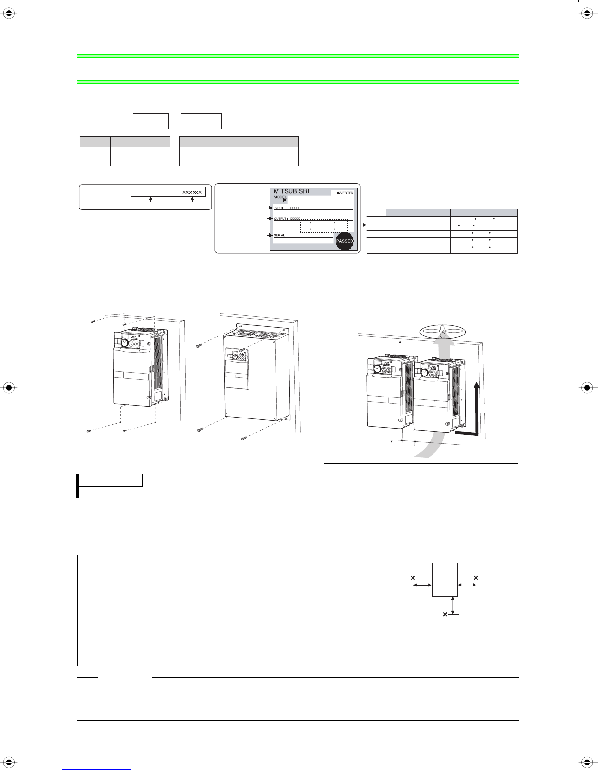
• Inverter Type
FR --A760
Symbol
A760
Capacity plate
Capacity plate
Voltage Class
Three-phase
600V class
FR-A760-00061-NA
Inverter type
00061 NA
Symbol
600V class
00017 to 00840
Rating plate
Serial number
-
Type number
Displays the
rated current
Rating plate
Inverter type
Input rating
Output rating
Serial number
FR-A760-00061-NA
ND (40 C) XXA
LD (40 C) XXA
SLD (40 C) XXA
HD (40 C) XXA
Overload current rating Ambient temperature
SLD
LD 120% 60s, 150% 3s 40 C (104 F)
ND 150% 60s, 200% 3s 40 C (104 F)
HD 200% 60s, 250% 3s 40 C (104 F)
• Installation of the inverter
Note - Some inverter models may be installed outside an enclosure. See Appendix 1 for details.
Installation on the enclosure
FR-A760-00330 or less FR-A760-00550 or more
CAUTION
• When encasing multiple inverters, install them in
parallel as a cooling measure.
• Install the inverter vertically.
110% 60s, 120% 3s
40 C (104 F)
30 C (86 F)(00061 or less)
Vertical
5
c
m(1.97
i
nc
h
es) o
r
mor
e
*
1
*1 1cm or more for FR-A760-00061 or less
REMARKS
To use an enclosed brake resistor for the FR-A760-00061 or less, refer to page 4.
General Precaution
•
The bus capacitor discharge time is 10 minutes. Before starting wiring or inspection, switch power off, wait for more than 10
minutes, and check for residual voltage between terminal P/+ and N/- with a meter etc., to avoid a hazard of electrical shock.
• Environment
Before installation, check that the environment meets following specifications.
Measurement
Ambient temperature
-10°C to +40°C (14°F to 104°F) (non-freezing)
SLD of 00061 or less : -10°C to +30°C (14°F to 86°F)
(non-freezing)
5cm
(1.97inches)
Measurement
position
Inverter
position
5cm
(1.97inches
5cm
(1.97inches)
Ambient humidity 90%RH or less (non-condensing)
Storage temperature -20°C to + 65°C (-4°F to 149°F)
Ambience Indoors (No corrosive and flammable gases, oil mist, dust and dirt.)
Altitude, vibration
Below 1000m, 5.9m/s2 or less
CAUTION
• Install the inverter on a strong surface securely and vertically with bolts.
• Leave enough clearances and take cooling measures.
• Avoid places where the inverter is subjected to direct sunlight, high temperature and high humidity.
• Install the inverter on a non-combustible wall surface.
1
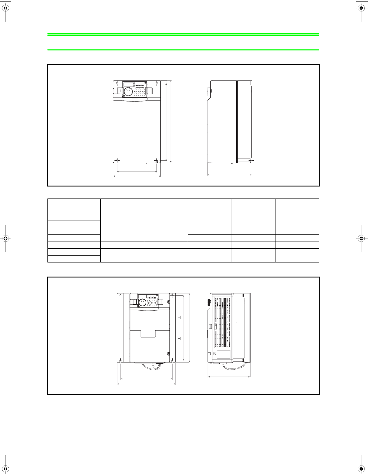
OUTLINE DIMENSION DRAWING
2 OUTLINE DIMENSION DRAWING
●When an enclosed brake resistor is not used
FR-A760-00017 to 00840-NA
H
H1
W1
W
D
(Unit:mm(inches))
• 600V class
Inverter Type W W1 H H1 D
FR-A760-00017-NA
150 (5.91) 125 (4.92)
FR-A760-00061-NA
FR-A760-00120-NA
FR-A760-00220-NA 300 (11.81) 285 (11.22) 190 (7.48)
FR-A760-00330-NA 250 (9.84) 230 (9.06) 400 (15.75) 380 (14.96) 190 (7.48)
FR-A760-00550-NA
FR-A760-00840-NA
220 (8.66) 195 (7.68)
435 (17.13) 380 (14.96) 550 (21.65) 525 (20.67) 250 (9.84)
260 (10.24) 245 (9.65)
140 (5.51)FR-A760-00040-NA
170 (6.69)
●When an enclosed brake resistor is used
FR-A760-00017 to 00061-NA
260 (10.23)
245 0.3 (9.64 0.01)
195 (7.68)
220 (8.66)
160 (6.29)
(Unit:mm(inches))
2
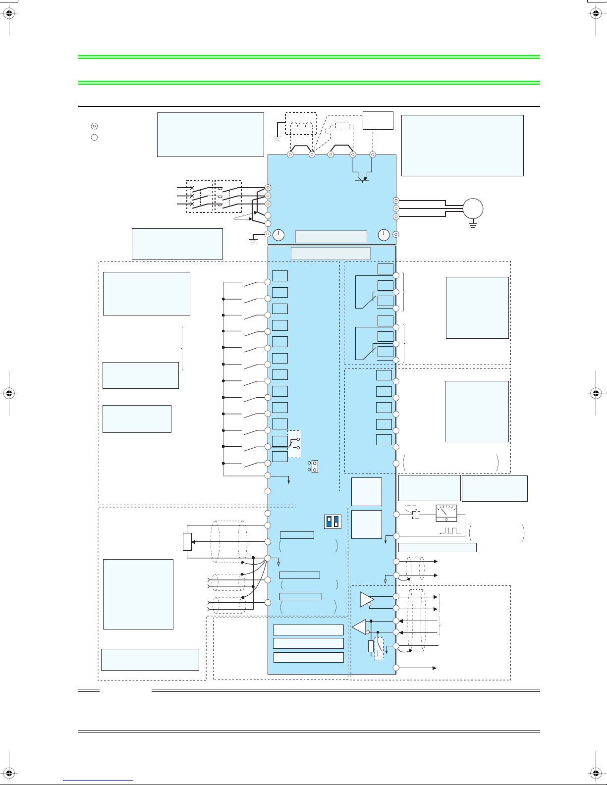
Terminal connection diagram
3 WIRING
3.1 Terminal connection diagram
Sink logic
Main circuit terminal
Control circuit terminal
*1. DC reactor
When using the FR-A760-00840 with LD
or SLD set, always use a DC reactor
(option).
When a DC reactor is connected to the
FR-A760-00840 or less, remove the
jumper across P1-P/+.
MCCB
MC
Earth
(Ground)
*1
Jumper
P1
R
*7
Jumper
PX PR N/-P/+
Brake unit
(Option)
*7. Brake resistor (Accessories)
The brake resistor is provided with the FRA760-00017 to 00061. Connect the accessory
brake resistor to P/+-PR.
Terminal PR is provided for the
.
to 00330
Install a thermal relay to prevent an overheat
and burnout of the brake resistor.
(Refer to the Instruction Manual (applied))
R/L1
Earth
S/L2
T/L3
R1/L11
S1/L21
Main circuit
Control circuit
STF
STR
STOP
RH
RM
RL
JOG
*3
RT
MRS
RES
*4
AU
AU
PTC
CS
SD
PC
10E(+10V)
10(+5V)
2
5
1
4
SOURCE
*5
Voltage/current
input switch
ON
OFF
0 to 5VDC
0 to 10VDC
0 to 20mADC
(Initial value)
selected
(Analog common)
±
10VDC
0 to
0 to ±5VDC
selected
4 to 20mADC
0 to 5VDC
0 to 10VDC
selected
Option connector 1
Option connector 2
Option connector 3
SINK
2
4
*5
(Initial value)
*5
(Initial value)
*5
C1
B1
A1
C2
B2
A2
RUN
SU
IPF
OL
FU
SE
PU
connector
USB
connector
FM
SD
*
10
AM
TXD+
TXD-
RXD+
RXD-
Terminating
VCC
resistor
U
V
W
Relay output 1
(Alarm output)
Relay output 2
Running
Up to frequency
Instantaneous
power failure
Overload
Frequency detection
Open collector output common
Sink
/source common
*
8. It is not necessary
when calibrating the
indicator from the
operation panel.
+
*9
Calibration
resistor *8
*10. USB connector is not used.
(+)
5
(-)
SG
5V
Three-phase AC
power supply
Jumper
*2. To supply power to the
control circuit separately,
remove the jumper across
R1/L11 and S1/L21.
Control input signals (No voltage input allowed)
Terminal functions vary with
the input terminal
assignment (Pr. 178 to Pr. 189)
(Refer to the Instruction
Manual (applied))
Forward
rotation
start
Reverse
rotation
start
Start self-
holding selection
High speed
Multi-speed
selection
*3. JOG terminal can be used
as pulse train input terminal.
Use Pr.291 to select
JOG/pulse.
Middle
speed
Low speed
Jog mode
Second function selection
*4. AU terminal can be
used as PTC input
terminal.
Terminal 4 input selection
(Current input selection)
Selection of automatic restart
Output stop
Reset
after instantaneous
power failure
Contact input common
24VDC power supply
(Common for external power supply transistor)
Frequency setting signal (Analog)
Frequency setting
potentiometer
1/2W1k
*
5.
Terminal input specifications
can be changed by analog
input specifications
switchover (Pr. 73, Pr. 267).
Set the voltage/current input
switch in the OFF position to
select voltage input (0 to 5V/0
to10V) and ON to select
current input (4 to 20mA).
(Refer to the Instruction
Manual (applied))
*6
3
Ω
1
Auxiliary
input
Terminal
4 input
(Current
input)
2
(+)
(+)
(-)
(-)
Connector
for plug-in option
connection
*6
. It is recommended to use 2W1kΩ
when the frequency setting signal
is changed frequently.
*2
(Ground)
CAUTION
· To prevent a malfunction due to noise, keep the signal cables more than 10cm (3.94inches) away from the power cables.
· After wiring, wire offcuts must not be left in the inverter.
Wire offcuts can cause an alarm, failure or malfunction. Alwa ys keep the inverter clean.
When drilling mounting holes in an enclosure etc., take care not to allow chips and other foreign matter to enter the inverter.
· Set the voltage/current input switch correctly. Different setting may cause a fault, failure or malfunction.
FR-A760-00017
Motor
IM
Earth (Ground)
Relay output
Terminal functions
vary with the output
terminal assignment
(Pr. 195, Pr. 196)
(Refer to the
Instruction Manual
(applied))
Open collector output
Terminal functions
vary with the output
terminal assignment
(Pr. 190 to Pr. 194)
(Refer to the
Instruction Manual
(applied))
*9. FM terminal can be
used for pulse train
output of open collector
output using Pr.291.
-
Indicator
(Frequency meter, etc.)
Moving-coil type
1mA full-scale
Analog signal output
(0 to 10VDC)
RS-485 terminals
Data transmission
Data reception
GND
(Permissible load
current 100mA)
3
WIRING
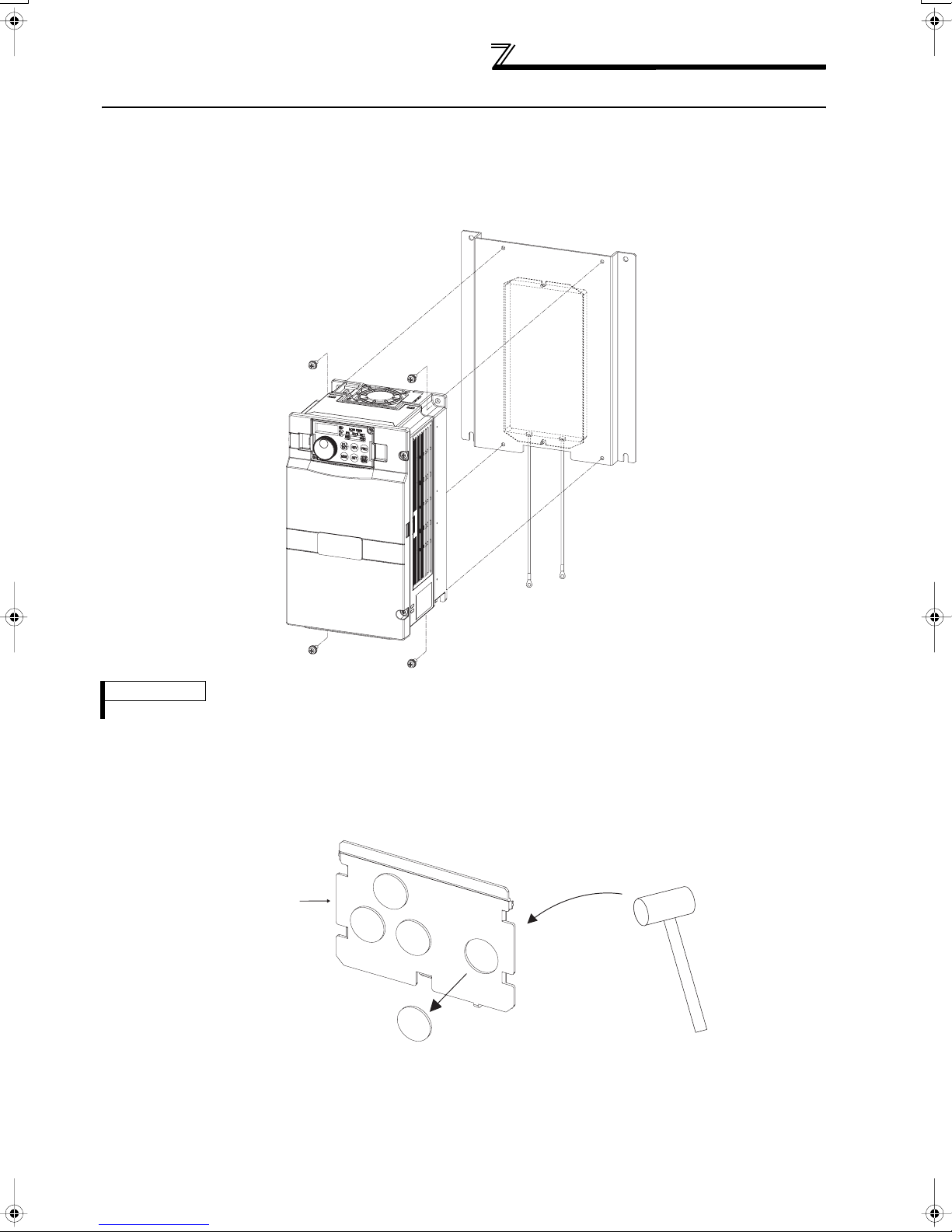
3.2 Connection of provided brake resistor
Connecting the brake resistor enclosed with the unit to the FR-A760-00017 to 00061 will improve regeneration
capability.
(1) Installation procedure
Connect the brake resistor to the inverter with provided screws.
REMARKS
Connecting the brake resistor changes the protective structure to OPEN type (NEMA1).
(2) Connection
Wiring cover and Handling (FR-A760-00061 or less)
1)Remove the wiring cover of the inverter. Punch out a knockout by firmly tapping it with such as a hammer. Remove
any sharp edges and burrs from knockout holes of the wiring cover.
Wiring cover
4
WIRING
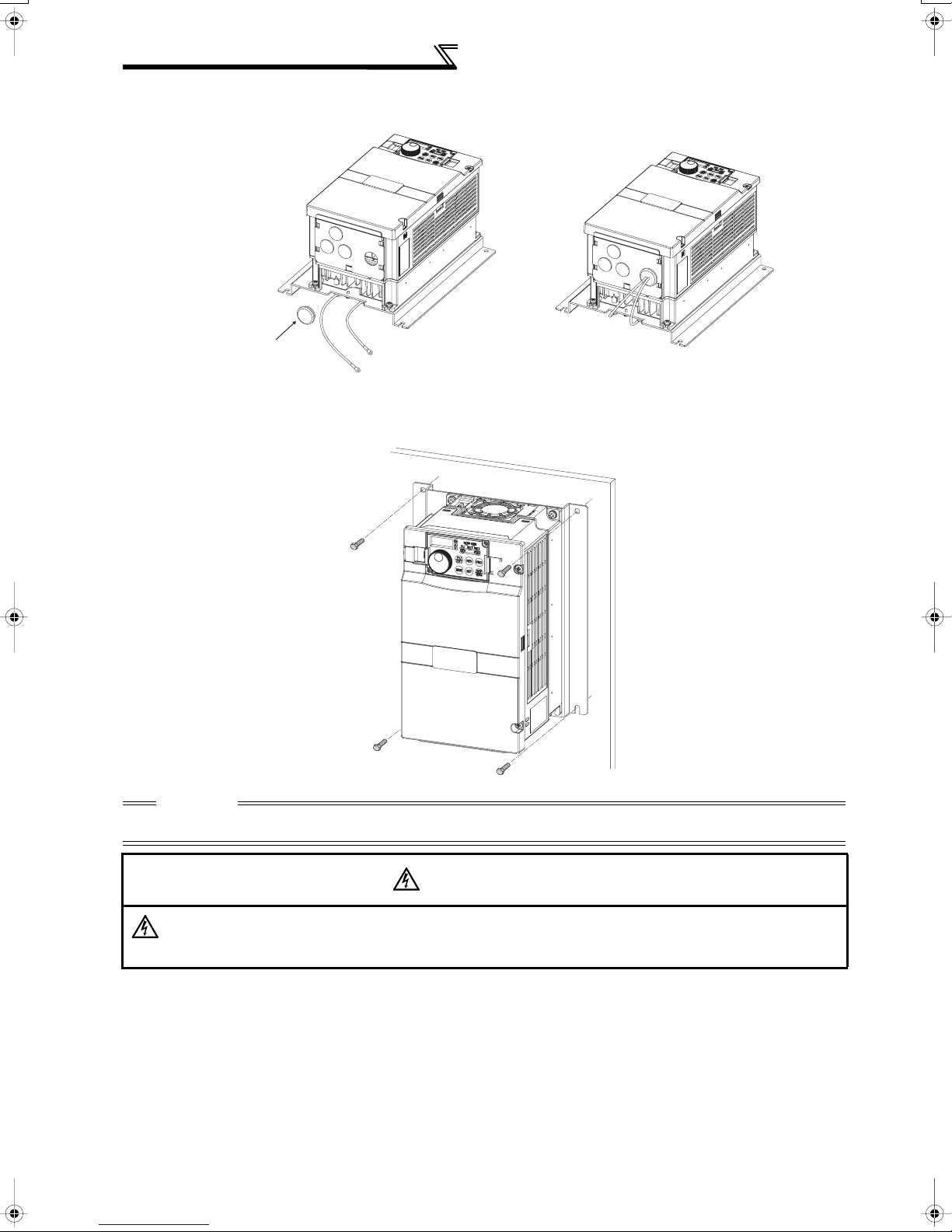
2)Attach protective bushes provided to the wiring cover and cut with nippers or a cutter before running the cables.
Connect the wire with red sleeve to PR terminal. Connect the wire with transparent sleeve to P/+.
Protective bushes
(Accessory)
(3) Installation of the inverter
(Red sleeve)
To PR terminal.
(Transparent sleeve)
To P/+ terminal.
CAUTION
When handling the wiring cover, care must be taken not to cut fingers or hands with sharp edges and burrs.
Avoide wire offcuts and other foreign matter from entering the inverter.
Do not wire without using protective bushes. Otherwise, the cable sheathes may be scratched by the wiring
cover edges, resulting in a short circuit or ground fault.
5
WARNING
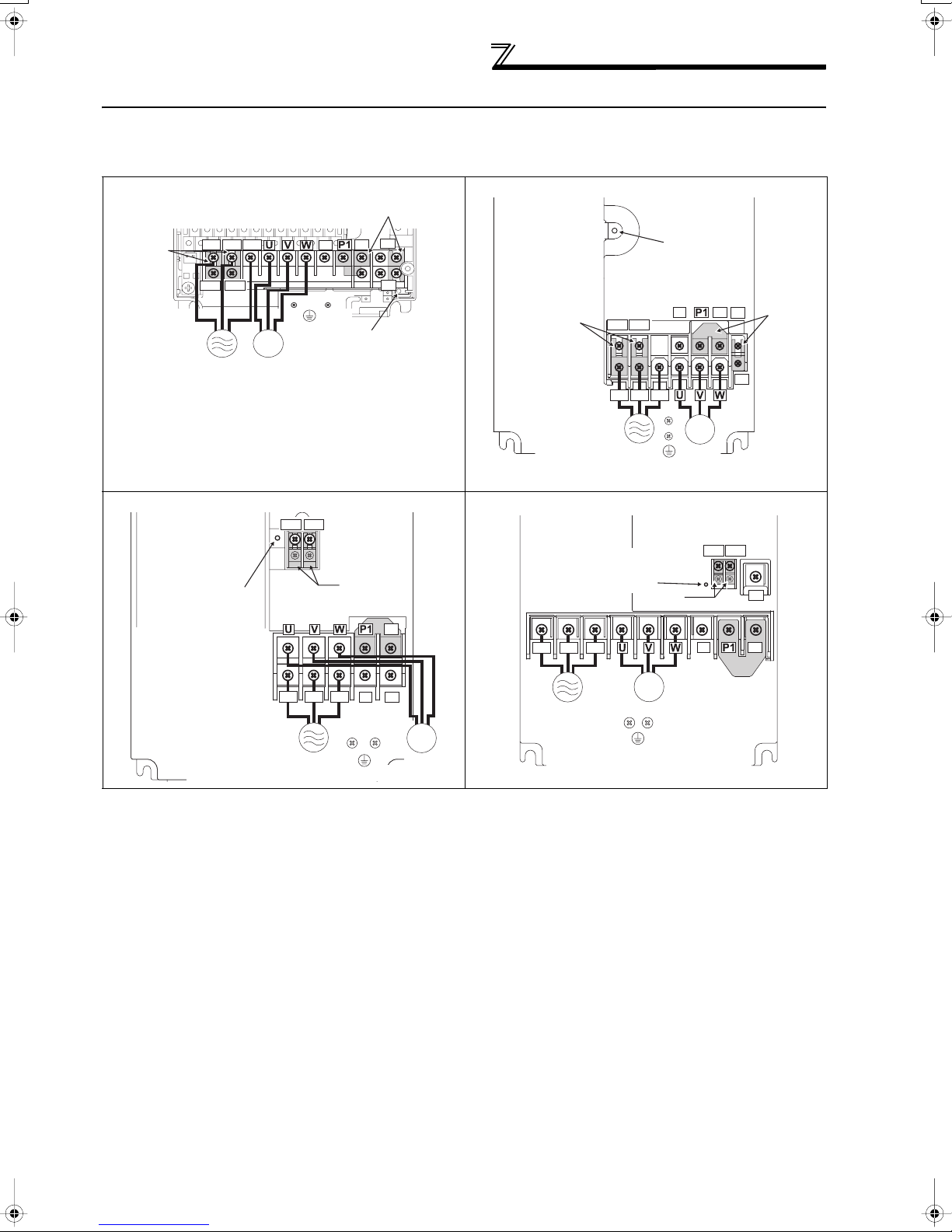
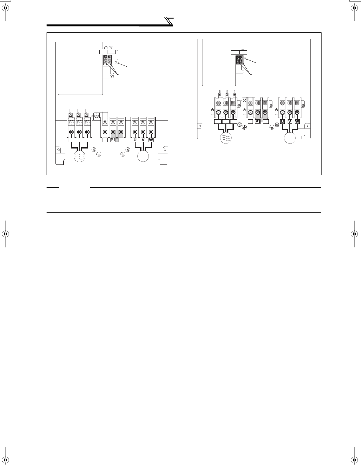
3.3 Main circuit terminal
r
(1) Terminal layout and wiring
600V class
FR-A760-00017 to 00061-NA FR-A760-00120-NA
Jumper
Screw size (M4)
R/L1 S/L2 T/L3
N/-
P/+
Jumper
PR
WIRING
Charge lamp
R1/L11 S1/L21
Power
supply
IM
Motor
Screw size
(M4)
PX
Jumper
Charge lamp
Screw size
FR-A760-00220-NA FR-A760-00330-NA
R1/L11 S1/L21
Screw size
(M4)
Charge lamp
Screw size (M5)
R/L1 S/L2 T/L3
Jumper
Jumper
N/-
P/+
PR
Screw size (M6)
R/L1 S/L2 T/L3
Power supply
R1/L11 S1/L21
(M4)
R/L1 S/L2 T/L3
Power supply
Charge lamp
N/-
IM
Motor
Screw size
(M4)
Screw size (M4)
Jumper
IM
Motor
P/+
PR
R1/L11 S1/L21
N/-
Jumper
Jumpe
PX
PR
P/+
Power supply
Screw size (M5)
IM
Motor
Screw size (M6)
6
WIRING
FR-A760-00550-NA FR-A760-00840-NA
Screw size(M4)
R/L1 S/L2 T/L3
Power
supply
R1/L11 S1/L21
Screw size(M8)
N/-
P/+
Jumper
Screw size(M8)
Charge lamp
Jumper
IM
Motor
Screw size (M4)
* When using the inverter with LD or SLD set, remove a jumper
between P/+ and P1 and connect a DC reactor.
R1/L11 S1/L21
R/L1 S/L2 T/L3
Power
supply
Charge lamp
Jumper
Screw size (M8)
N/-
P/+
Jumper *
Screw size (M8)
IM
Motor
CAUTION
· The power supply cables must be connected to R/L1, S/L2, T/L3. Never connect the power cable to the U, V, W of the inverter.
Doing so will damage the inverter. (Phase sequence needs not to be matched.)
· Connect the motor to U, V, W. At this time, turning on the forward rotation switch (signal) rotates the motor in the
counterclockwise direction when viewed from the motor shaft.
7
 Loading...