

Mitsubishi Electric FR-A741-5.5K, FR-A741-7.5K, FR-A741-11K, FR-A741-15K, FR-A741-22K Installation Manual
...
MITSUBISHI ELECTRIC
Frequency Inverter
Installation Guideline
Art. No. 224739
08 04 2009
rs i o n A
Ve
FR-A741-5.5K to 55K
MITSUBISHI ELECTRIC
INDUSTRIAL AUTOMATION

Thank you for choosing this Mitsubishi Inverter.
Please read through this Installation Manual and the Instruction Manual to operate this inverter correctly
Do not use this product until you have a full knowledge of the equipment, the safety information and the
instructions.
Please forward this manual to the end user.
CONTENTS
INSTALLATION OF THE INVERTER AND INSTRUCTIONS ...................................1
1
OUTLINE DIMENSION DRAWING ............................................................................3
2
WIRING ......................................................................................................................4
3
PRECAUTIONS FOR THE USEOF THE INVERTER ................................................9
4
FAILSAFE OF THE SYSTEM WHICH USES THE INVERTER............................... 11
5
PARAMETER ...........................................................................................................12
6
TROUBLESHOOTING ............................................................................................. 22
7
APPENDIX ...............................................................................................................24
A

Print Date Manual Number Revision
04/2009 pdp-gb 224739 First edition
For Maximum Safety
Mitsubishi transistorized inverters are not designed or manufactured to be used in equipment or systems in situations
that can affect or endanger human life.
When considering this product for operation in special applications such as machinery or systems used in passenger
transportation, medical, aerospace, atomic power, electric power, or submarine repeating applications, please contact
your nearest Mitsubishi sales representative.
Although this product was manufactured under conditions of strict quality control, you are strongly advised to install
safety devices to prevent serious accidents when it is used in facilities where breakdowns of the product are likely to
cause a serious accident.
Please do not use this product for loads other than three-phase induction motors.
Please check upon receiving of the inverter whether this Installation Guideline corresponds to the delivered inverter.
Compare the specifications on the capacity plate with the specifications given in this Installation Guideline.
This section is specifically about safety matters
WARNING
CAUTION
CAUTION
WARNING
CAUTION
CAUTION
CAUTION
Operating condition
Ambient temperature −10°C to +50°C (non-freezing)
Ambient humidity 90% RH or less (non-condensing)
Storage temperature
−20°C to +65°C
햲
Atmosphere Indoors (free from corrosive gas, flammable gas, oil mist, dust and dirt)
Altitude Maximum 1000m above sea level for standard operation.
Vibration
5.9m/s² or less
Do not attempt to install, operate, maintain or inspect the inverter until you have read through this Installation Guideline and appended
documents carefully and can use the equipment correctly. Do not use the inverter until you have a full knowledge of the equipment,
safety information and instructions. In this Installation Guideline, the safety instruction levels are classified into "WARNING" and
"CAUTION".
Assumes that incorrect handling may cause hazardous conditions, resulting in death or severe injury.
Assumes that incorrect handling may cause hazardous conditions, resulting in medium or slight injury, or may
cause physical damage only.
Note that even the level may lead to a serious consequence according to conditions. Please follow strictly the instructions
of both levels because they are important to personnel safety.
Electric Shock Prevention
While power is on or when the inverter is running, do not open the front cover or wiring cover. Otherwise you may get an electric
shock.
Do not run the inverter with the front cover removed. Otherwise, you may access the exposed high-voltage terminals or the charging
part of the circuitry and get an electric shock.
Even if power is off, do not remove the front cover except for wiring or periodic inspection.You may access the charged inverter circuits and
get an electric shock.
Before starting wiring or inspection, check to make sure that the operation panel indicator is off, wait for at least 10 minutes after the
power supply has been switched off, and check that there are no residual voltage using a tester or the like. The capacitor is charged
with high voltage for some time after power off and it is dangerous.
This inverter must be earthed (grounded). Earthing (Grounding) must conform to the requirements of national and local safety regulations
and electrical codes. (NEC section 250, IEC 536 class 1 and other applicable standards)
Any person who is involved in the wiring or inspection of this equipment should be fully competent to do the work.
Always install the inverter before wiring. Otherwise, you may get an electric shock or be injured.
Perform setting dial and key operations with dry hands to prevent an electric shock. Otherwise you may get an electric shock.
Do not subject the cables to scratches, excessive stress, heavy loads or pinching. Otherwise you may get an electric shock.
Do not replace the cooling fan while power is on. It is dangerous to replace the cooling fan while power is on.
t touch the printed circuit board with wet hands. You may get an electric shock
Do no
When measuring the main circuit capacitor capacity, the DC voltage is applied to the motor for 1s at powering off. Never touch the
motor terminal, etc. right after powering off to prevent an electric shock.
.
Fire Prevention
Install the inverter on a nonflammable wall without holes (so that nobody can touch the inverter heatsink on the rear side, etc.). Mounting it to or near
combustible material can cause a fire.
If the inverter has become faulty, switch off the inverter power. A continuous flow of large current could cause a fire.
When using a brake resistor, make up a sequence that will turn off power when an alarm signal is output.
excessively overheat due to damage of the brake transistor and such, causing a fire
Do not connect a resistor directly to the DC terminals P, N. This could cause a fire and destroy the inverter. The surface temperature of
braking resistors can far exceed 100°C for brief periods. Make sure that there is adequate protection against accidental contact and a safe
distance is maintained to other units and system parts
.
.
Otherwise,
the brake resistor may
Injury Prevention
Apply only the voltage specified in the instruction manual to each terminal. Otherwise, burst, damage, etc. may occur.
Ensure that the cables are connected to the correct terminals. Otherwise, burst, damage, etc. may occur.
Always make sure that polarity is correct to prevent damage, etc. Otherwise, burst, damage, etc. may occur.
While power is on or for some time after power-off, do not touch the inverter as it is hot and you may get burnt
.
Additional Instructions
Also note the following points to prevent an accidental failure, injury, electric shock, etc.
Transportation and Installation
Transport the product using the correct method that corresponds to the weight. Failure to observe this could lead to injuries.
Do not stack the inverter boxes higher than the number recommended.
Ensure that installation position and material can withstand the weight of the inverter. Install according to the information in the instruction
manual.
Do not install or operate the inverter if it is damaged or has parts missing. This can result in breakdowns.
When carrying the inverter, do not hold it by the front cover or setting dial; it may fall off or fail.
Do not stand or rest heavy objects on the product.
Check the inverter mounting orientation is correct.
Prevent other conductive bodies such as screws and metal fragments or other flammable substance such as oil from entering the
inverter.
As the inverter is a precision instrument, do not drop or subject it to impact.
Use the inverter under the following environmental conditions. Otherwise, the inverter may be damaged.
햲
Temperature applicable for a short time, e.g. in transit.
Wiring
CAUTION
CAUTION
WARNING
CAUTION
CAUTION
CAUTION
CAUTION
Do not install assemblies or components (e. g. power factor correction capacitors) on the inverter output side, which are not approved
from Mitsubishi.
The direction of rotation of the motor corresponds to the direction of rotation commands (STF/STR) only if the phase sequence (U, V,
W) is maintained.
Test operation and adjustment
Before starting operation, confirm and adjust the parameters. A failure to do so may cause some machines to make unexpected
motions.
Operation
When you have chosen the retry function, stay away from the equipment as it will restart suddenly after an alarm stop.
The key is valid only when the appropriate function setting has been made. Prepare an emergency stop switch separately to
make an emergency stop (power off, mechanical brake operation for emergency stop, etc).
Make sure that the start signal is off before resetting the inverter alarm. A failure to do so may restart the motor suddenly.
The inverter can be started and stopped via the serial port communications link or the field bus. However, please note that depending
on the settings of the communications parameters it may not be possible to stop the system via these connections if there is an error
in the communications system or the data line. In configurations like this it is thus essential to install additional safety hardware that
makes it possible to stop the system in an emergency (e.g. controller inhibit via control signal, external motor contactor etc). Clear and
unambiguous warnings about this must be posted on site for the operating and service staff.
Performing pre-excitation (LX signal and X13 signal) under torque control (real sensorless vector control) may start the motor running
at a low speed even when the start command (STF or STR) is not input. The motor may run also at a low speed when the speed limit
value = 0 with a start command input. Perform pre-excitation after making sure that there will be no problem in safety if the motor runs.
The load used should be a three-phase induction motor only. Connection of any other electrical equipment to the inverter output may
damage the inverter as well as the equipment.
Do not modify the equipment.
Do not perform parts removal which is not instructed in this manual. Doing so may lead to fault or damage of the inverter.
The electronic thermal relay function does not guarantee protection of the motor from overheating.
Do not use a magnetic contactor on the inverter input for frequent starting/stopping of the inverter.
Use a noise filter to reduce the effect of electromagnetic interference and follow the accepted EMC procedures for proper installation
of frequency inverters. Otherwise nearby electronic equipment may be affected.
Take appropriate measures regarding harmonics. Otherwise this can endanger compensation systems or overload generators.
When a 400V class motor is inverter-driven, please use an insulation-enhanced motor or measures taken to suppress surge voltages.
Surge voltages attributable to the wiring constants may occur at the motor terminals, deteriorating the insulation of the motor.
When parameter clear or all clear is performed, set again the required parameters before starting operations. Each parameter returns
to the initial value.
The inverter can be easily set for high-speed operation. Before changing its setting, fully examine the performances of the motor and
machine.
The DC braking function of the frequency inverter is not designed to continuously hold a load. Use an electro-mechanical holding
brake on the motor for this purpose.
Before running an inverter which had been stored for a long period, always perform inspection and test operation.
For prevention of damage due to static electricity, touch nearby metal before touching this product to eliminate static electricity from
your body
.
Emergency stop
Provide a safety backup such as an emergency brake which will prevent the machine and equipment from hazardous conditions if the
inverter fails.
When the breaker on the inverter primary side trips, check for the wiring fault (short circuit), damage to internal parts of the inverter,
etc. Identify the cause of the trip, then remove the cause and power on the breaker.
When the protective function is activated (i. e. the frequency inverter switches off with an error message), take the corresponding
corrective action as described in the inverter manual, then reset the inverter, and resume operation
.
Maintenance, inspection and parts replacement
Do not carry out a megger (insulation resistance) test on the control circuit of the inverter.
Disposing of the inverter
Treat as industrial waste.
General instructions
Many of the diagrams and drawings in instruction manuals show the inverter without a cover, or partially open. Never run the inverter in
this status. Always replace the cover and follow instruction manuals when operating the inverter.
1
5.5
5.5
5.5
A741
A741
A741
K
K
K
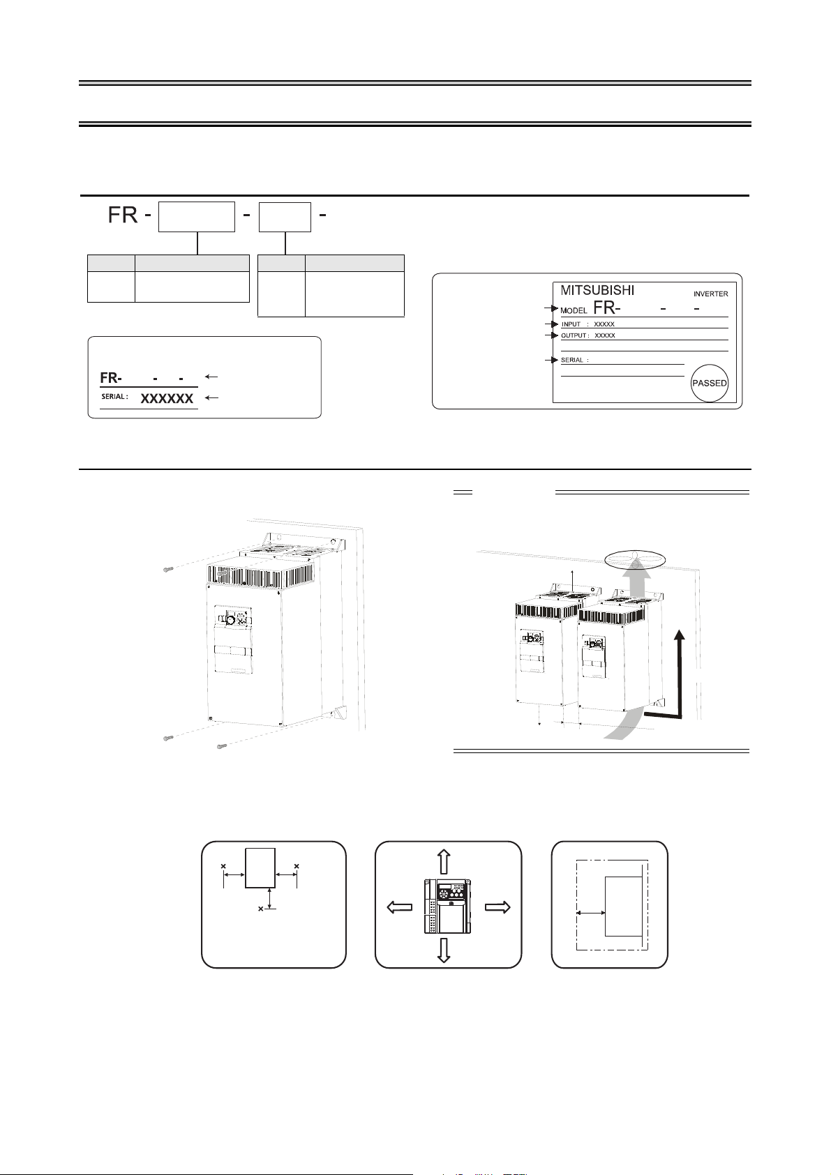
1.1 Inverter Type
Symbol Voltage Class
A741
Three-phase
400V class
Symbol Type number
5.5
to
55
Indicate inverter
capacity [kW]
Capacity plate example
Rating plate example
Capacity plate
Rating plate
Serial number
Inverter type
Inverter type
Input rating
Output rating
Serial number
CAUTION
When encasing multiple inverters, install them in parallel as a
cooling measure.
Install the inverter vertically.
vertical
R
e
f
e
r
t
o
t
h
e
c
le
a
r
a
n
c
e
s
b
e
lo
w
.
Ambient air temperature and
humidity
Clearances (side)
5cm
5cm
5cm
Inverter
Measurement
position
Temperature: −10°C to +50°C
Humidity: max. 90%
≥ 5cm
Leave enough clearances
and take cooling measures.
Clearances (front)
≥ 5cm
≥ 10cm
≥ 10cm
Inverter
≥ 5cm
Measurement
position
INSTALLATION OF THE INVERTER AND INSTRUCTIONS
Unpack the inverter and check the capacity plate on the front cover and the rating plate on the inverter side face to
ensure that the product agrees with your order and the inverter is intact.
1.2 Installation of the inverter
Enclosure surface mounting
1

INSTALLATION OF THE INVERTER AND INSTRUCTIONS
1.3 General Precaution
The bus capacitor discharge time is 10 minutes. Before starting wiring or inspection, switch power off, wait for more than
10 minutes, and check for residual voltage between terminal P/+ and N/− with a meter etc., to avoid a hazard of electrical
shock.
1.4 Environment
Before installation, check that the environment meets following specifications.
Ambient temperature −10°C to +50°C (non-freezing)
Ambient humidity 90 % RH or less (non-condensing)
Atmosphere
Maximum altitude
Vibration
CAUTION
Install the inverter on a strong surface securely and vertically with bolts.
Leave enough clearances and take cooling measures.
Avoid places where the inverter is subjected to direct sunlight, high temperature and high humidity.
Install the inverter on a non-combustible surface.
Free from corrosive and explosive gases, free from dust and dirt
Maximum 1000 m above sea level
5.9m/s² or less
2
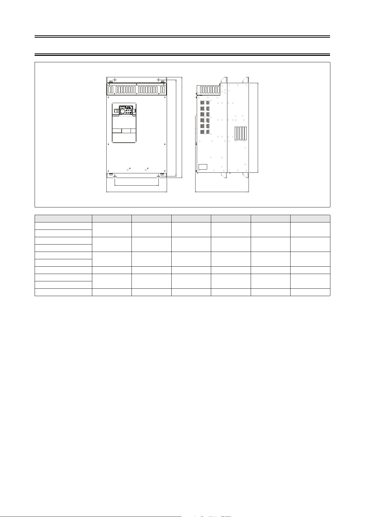
2 OUTLINE DIMENSION DRAWING
W1
W
H
1
H
D
H
2
(Unit: mm)
Inverter Type W W1 H H1 H2 D
FR-A741-5.5K
FR-A741-7.5K
FR-A741-11K
FR-A741-15K
FR-A741-18.5K
FR-A741-22K
FR-A741-30K 450 350 700 675 635 340
FR-A741-37K
FR-A741-45K
FR-A741-55K 600 480 900 870 830 405
250 190 470 454 425 270
300 220 600 575 540 294
360 260 600 575 535 320
470 370 700 670 630 368
3
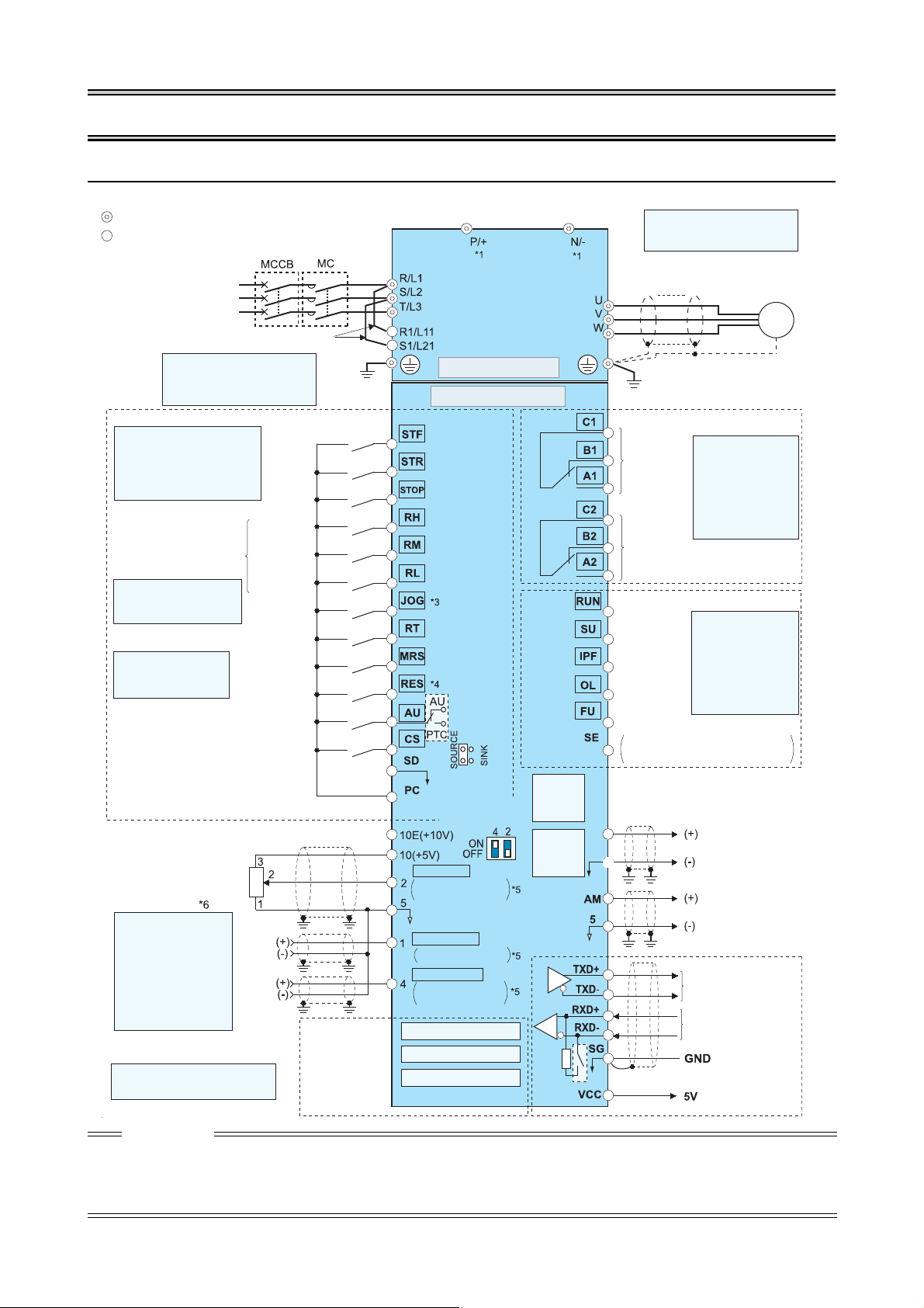
3 WIRING
FM
SD
Source logic
Main circuit terminal
Control circuit terminal
Jumper
*2
Earth
*1 Do not connect any options
to P/+ and N/−.
Motor
*2 To supply power to the
control circuit separately,
remove the jumper across
R1/L11 and S1/L21.
3-phase AC
power supply
Main circuit
Control circuit
Terminal functions vary with
the input terminal
assignment.
(Pr. 178 to Pr. 189)
Control input signals (No voltage input allowed)
Forward
rotation
start
Reverse
rotation
start
Star t se lf -
holding
selection
High
speed
Middle
speed
Low
speed
Multi-speed selection
Jog mode
Second function selection
Output stop
Reset
Current input selection
Selection of automatic restart after
instantaneous power failure
Contact input common (Sink*)
*3 JOG terminal can be used
as pulse train input
terminal. Use
Pr. 29
1 to
select JOG/pulse.
24 V DC power supply/max. 100 mA load current
Contact input common (Source*)
*(Common for external power supply transistor)
Frequency setting signal (Analog)
Auxiliary
input
Terminal 4
input
(Current
input)
0–5V DC
0– ±10V DC
4–20mA DC
0 to 10V DC
0 to 20mA DC
0 to ±5V DC
0 to 5V DC
0 to 10V DC
PU
connector
Connector for
plug-in option
connection
Option connector 1
Terminating
resistor
*5 Terminal input specifica
tions can be changed by
analog input specifications
switchover
(Pr. 73, Pr. 267)
.
Set the voltage/current
input switch in the OFF
position to select voltage
input (0 to 5V/0 to10V) and
ON to select current input
(4 to 20mA).
*6 It is recommended to use 1kΩ, 2W
potentiometer when the frequency
setting signal is changed frequently.
Relay output 1
(Fault output)
Relay output 2
Running
Instantaneous
power failure
Up to frequency
Overload
Terminal functions
vary with the output
terminal assignment
(Pr. 195, Pr. 196)
Terminal functions
vary with the output
terminal assignment
(Pr. 190 to Pr. 194)
Frequency detection
Open collector output common
Sink/source common
Pulse output
Analog signal output
(0 to 10VDC)
RS-485 terminals
Data transmission
Data reception
(Permissible load
current 100mA)
Frequency setting
potentiometer
1k
Ω, 1/2W
M
3~
*4 AU terminal can be
used as PTC input
terminal.
*5 Voltage/
current
input switch
Option connector 2
Option connector 3
Relay output
USB
connector
Open collector output
3.1 Terminal connection diagram
To prevent a malfunction due to noise, keep the signal cables more than 10cm away from the power cables. Also separate the main
circuit wire of the input side and the output side.
After wiring, wire offcuts must not be left in the inverter. Wire offcuts can cause an alarm, failure or malfunction. Always keep the
inverter clean. When drilling mounting holes in an enclosure etc., take care not to allow chips and other foreign matter to enter the
inverter.
Set the voltage/current input switch correctly. Different setting may cause a fault, failure or malfunction.
4
CAUTION
WIRING
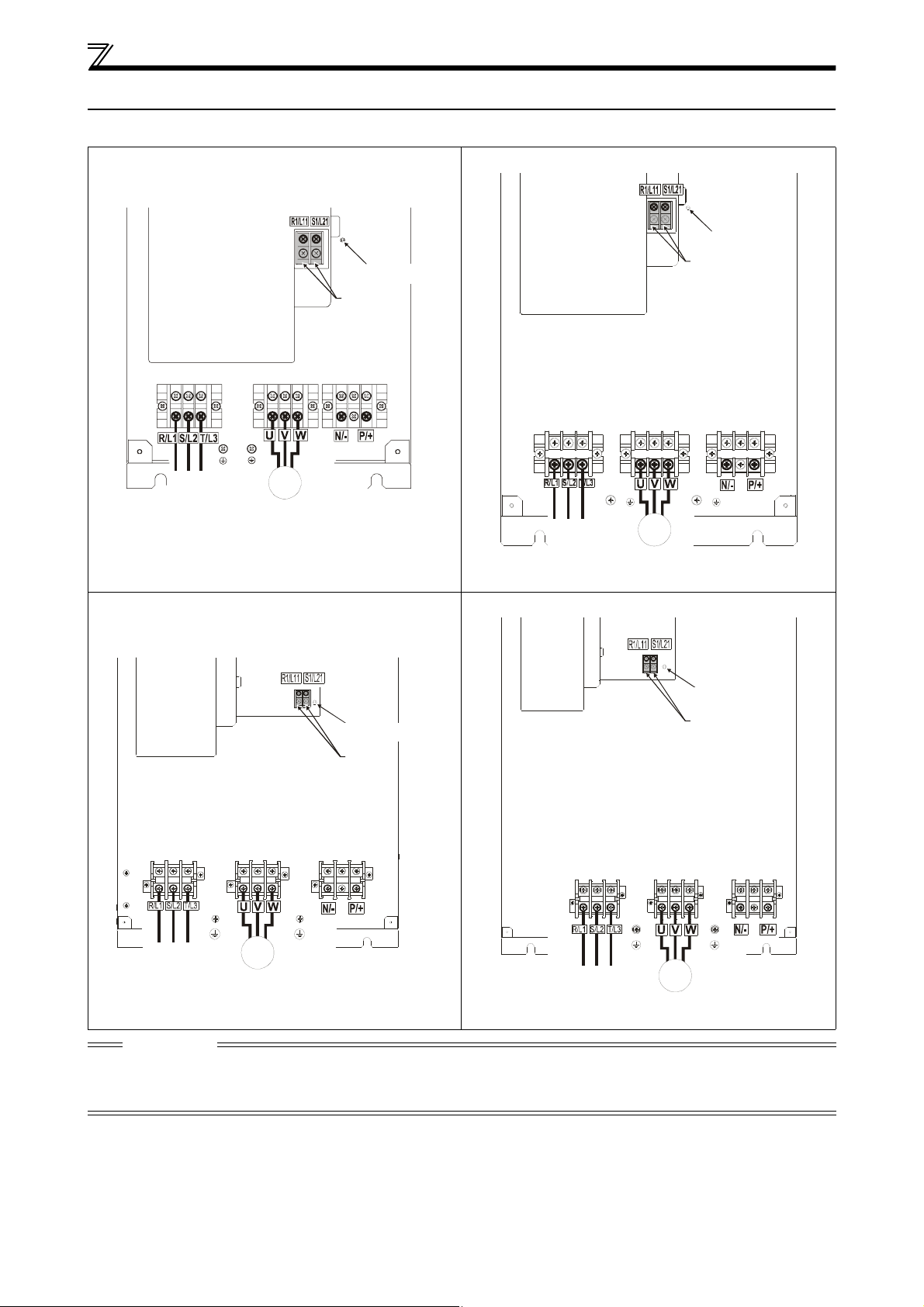
Screw size (M4)
Jumper
Charge lamp
Motor
Power supply
M
3 ~
L1 L2 L3
Screw size
(M4)
Jumper
Charge lamp
Power supply
Screw size (M5)
Motor
Screw size
(M4)
M
3 ~
L1 L2 L3
Screw size
(M4)
Charge lamp
Jumper
Screw size
(18.5K to 30K: M6)
37K and 45K: M8)
Power
supply
Motor
M
3 ~
L1 L2 L3
Screw size (M4)
Power supplyg
Motor
Jumper
Charge lamp
M
3 ~
L1 L2 L3
Screw size (M8)
3.2 Main circuit terminal specifications
3.2.1 Terminal arrangement of the main circuit terminal, power supply and the motor wiring
FR-A741-5.5K, 7.5K FR-A741-11K, 15K
FR-A741-18.5K to 45K FR-A741-55K
ACHTUNG
The power supply cables must be connected to R/L1, S/L2, T/L3. (Phase sequence needs not to be matched.) Never connect the
power cable to the U, V, W of the inverter. Doing so will damage the inverter.
Connect the motor to U, V, W. At this time turning on the forward rotation switch (signal) rotates the motor in the clockwise direction
when viewed on the motor shaft.
5
 Loading...