

Mitsubishi FR-A720-22K, FR-A740-0.4K, FR-A720-37K, FR-A720-55K, FR-A720-75K Instruction Manual
...
3
4
5
6
1
2
FR-A700
INSTRUCTION MANUAL (Applied)
INVERTER
PRECAUTIONS FOR USE
OF THE INVERTER
PARAMETERS
PROTECTIVE FUNCTIONS
PRECAUTIONS FOR
MAINTENANCE AND INSPECTION
OUTLINE
WIRING
FR-A720-0.4K to 90K
FR-A740-0.4K to 500K
Thank you for choosing this Mitsubishi Inverter.
This Instruction Manual (applied) provides instructions for advanced use of the FR-A700 series inverters.
Incorrect handling might cause an unexpected fault. Before using the inverter, always read this instruction manual and the instruction manual
(basic) [IB-0600225ENG] packed with the product carefully to use the equipment to its optimum.
This section is specifically about safety matters
Do not attempt to install, operate, maintain or inspect the inverter until you
have read through instruction manual (basic) and appended documents
carefully and can use the equipment correctly. Do not use the inverter until
you have a full knowledge of the equipment, safety information and
instructions. In this instruction manual, the safety instruction levels are
classified into "WARNING" and "CAUTION".
WARNING
CAUTION
Note that even the level may lead to a serious consequence
according to conditions. Please follow strictly the instructions of both levels
because they are important to personnel safety.
1. Electric Shock Prevention
• While power is on or when the inverter is running, do not open the front cover.
Otherwise you may get an electric shock.
• Do not run the inverter with the front cover or wiring cover removed.
Otherwise, you may access the exposed high-voltage terminals or the charging
part of the circuitry and get an electric shock.
•
Even if power is off, do not remove the front cover except for wiring or periodic
inspection.You may access the charged inverter circuits and get an electric shock.
• Before starting wiring or inspection, check to make sure that the operation panel
indicator is off, wait for at least 10 minutes after the power supply has been
switched off, and check that there are no residual voltage using a tester or the
like. The capacitor is charged with high voltage for some time after power off and
it is dangerous.
• This inverter must be earthed
the requirements of national and local safety regulations and electrical codes.
(JIS, NEC section 250, IEC 536 class 1 and other applicable standards)
• Any person who is involved in the wiring or inspection of this equipment should
be fully competent to do the work.
• Always install the inverter before wiring. Otherwise, you may get an electric shock
or be injured.
• Perform setting dial and key operations with dry hands to prevent an electric
shock. Otherwise you may get an electric shock.
• Do not subject the cables to scratches, excessive stress, heavy loads or
pinching. Otherwise you may get an electric shock.
• Do not replace the cooling fan while power is on. It is dangerous to replace the
cooling fan while power is on.
Do not touch the printed circuit board with wet hands. You may get an electric shock.
•
2. Fire Prevention
• Mount the inverter to non-combustible surface such as metal or concrete.
Mounting it to or near combustible material can cause a fire.
• If the inverter has become faulty, switch off the inverter power.
A continuous flow of large current could cause a fire.
• When using a brake resistor, make up a sequence that will turn off power when
an alarm signal is output.
Otherwise, the brake resistor may excessively overheat due to damage of the
brake transistor and such, causing a fire.
•
Do not connect a resistor directly to the DC terminals P/+, N/−. This could cause a fire.
3. Injury Prevention
• Apply only the voltage specified in the instruction manual to each terminal.
Otherwise, burst, damage, etc. may occur.
• Ensure that the cables are connected to the correct terminals. Otherwise, burst,
damage, etc. may occur.
• Always make sure that polarity is correct to prevent damage, etc. Otherwise,
burst, damage, etc. may occur.
• While power is on or for some time after power-off, do not touch the inverter as it
is hot and you may get burnt.
4. Additional Instructions
Also note the following points to prevent an accidental failure, injury, electric
shock, etc.
(1) Transportation and installation
• When carrying products, use correct lifting gear to prevent injury.
• Do not stack the inverter boxes higher than the number recommended.
• Ensure that installation position and material can withstand the weight of the
inverter. Install according to the information in the instruction manual.
• Do not install or operate the inverter if it is damaged or has parts missing. This can
result in breakdowns.
• When carrying the inverter, do not hold it by the front cover or setting dial; it may
fall off or fail.
• Do not stand or rest heavy objects on the product.
• Check the inverter mounting orientation is correct.
• Prevent other conductive bodies such as screws and metal fragments or other
flammable substance such as oil from entering the inverter.
• As the inverter is a precision instrument, do not drop or subject it to impact.
• Use the inverter under the following environmental conditions. Otherwise, the
inverter may be damaged.
Ambient temperature -10°C to +50°C (non-freezing)
Ambient humidity 90% RH or less (non-condensing)
Storage temperature -20°C to +65°C
Atmosphere
Altitude, vibration
Environment
*1 Temperature applicable for a short time, e.g. in transit.
*2 2.9m/s
Assumes that incorrect handling may cause hazardous
conditions, resulting in death or severe injury.
Assumes that incorrect handling may cause
hazardous conditions, resulting in medium or slight
injury, or may cause physical damage only.
CAUTION
WARNING
(grounded). Earthing (Grounding) must conform to
CAUTION
CAUTION
CAUTION
Indoors (free from corrosive gas, flammable
gas, oil mist, dust and dirt)
Maximum 1000m above sea level for standard
operation. 5.9m/s2 or less *2 (conforming to
JIS C 60068-2-6)
2
or less for the 160K or more.
*1
(2) Wiring
• Do not install a power factor correction capacitor or surge suppressor/radio
noise filter (capacitor type filter) on the inverter output side.
• The connection orientation of the output cables U, V, W to the motor will affect
the direction of rotation of the motor.
CAUTION
(3) Test operation and adjustment
• Before starting operation, confirm and adjust the parameters. A failure to do so
may cause some machines to make unexpected motions.
(4) Operation
• When you have chosen the retry function, stay away from the equipment as it
will restart suddenly after an alarm stop.
• The key is valid only when the appropriate function setting has been
made. Prepare an emergency stop switch separately.
• Make sure that the start signal is off before resetting the inverter alarm. A failure
to do so may restart the motor suddenly.
• The load used should be a three-phase induction motor only. Connection of any
other electrical equipment to the inverter output may damage the inverter as well as
equipment.
• Performing pre-excitation (LX signal and X13 signal) under torque control (real
sensorless vector control) may start the motor running at a low speed even
when the start command (STF or STR) is not input. The motor may run also at a
low speed when the speed limit value = 0 with a start command input. Perform
pre-excitation after making sure that there will be no problem in safety if the
motor runs.
• Do not modify the equipment.
• Do not perform parts removal which is not instructed in this manual. Doing so
may lead to fault or damage of the inverter.
• The electronic thermal relay function does not guarantee protection of the motor
from overheating.
• Do not use a magnetic contactor on the inverter input for frequent starting/
stopping of the inverter.
• Use a noise filter to reduce the effect of electromagnetic interference. Otherwise
nearby electronic equipment may be affected.
• Take measures to suppress harmonics. Otherwise power supply harmonics from
the inverter may heat/damage the power factor correction capacitor and
generator.
• When a 400V class motor is inverter-driven, please use an insulation-enhanced
motor or measures taken to suppress surge voltages. Surge voltages
attributable to the wiring constants may occur at the motor terminals,
deteriorating the insulation of the motor.
• When parameter clear or all clear is performed, reset the required parameters
before starting operations. Each parameter returns to the initial value.
• The inverter can be easily set for high-speed operation. Before changing its
setting, fully examine the performances of the motor and machine.
• In addition to the inverter's holding function, install a holding device to ensure
safety.
• Before running an inverter which had been stored for a long period, always
perform inspection and test operation.
• For prevention of damage due to static electricity, touch nearby metal before
touching this product to eliminate static electricity from your body.
(5) Emergency stop
• Provide a safety backup such as an emergency brake which will prevent the
machine and equipment from hazardous conditions if the inverter fails.
• When the breaker on the inverter input side trips, check for the wiring fault (short
circuit), damage to internal parts of the inverter, etc. Identify the cause of the trip,
then remove the cause and power on the breaker.
• When the protective function is activated, take the corresponding corrective
action, then reset the inverter, and resume operation.
CAUTION
WARNING
CAUTION
CAUTION
(6) Maintenance, inspection and parts replacement
• Do not carry out a megger (insulation resistance) test on the control circuit of the
inverter.
CAUTION
(7) Disposing of the inverter
• Treat as industrial waste.
CAUTION
General instructions
Many of the diagrams and drawings in this instruction manual show the inverter
without a cover, or partially open. Never run the inverter in this status. Always
replace the cover and follow this instruction manual when operating the
inverter.
A-1

CONTENTS
1 OUTLINE 1
1.1 Product checking and parts identification ........................................................ 2
1.2 Inverter and peripheral devices.......................................................................... 3
1.2.1 Peripheral devices ..................................................................................................................... 4
1.3 Method of removal and reinstallation of the front cover.................................. 6
1.4 Installation of the inverter and enclosure design ............................................. 8
1.4.1 Inverter installation environment................................................................................................ 8
1.4.2 Cooling system types for inverter enclosure............................................................................ 10
1.4.3 Inverter placement................................................................................................................... 10
2 WIRING 13
2.1 Wiring..................................................................................................................14
2.1.1 Terminal connection diagram .................................................................................................. 14
2.1.2 EMC filter................................................................................................................................. 15
2.2 Main circuit terminal specifications ................................................................. 16
2.2.1 Specification of main circuit terminal ....................................................................................... 16
2.2.2 Terminal arrangement of the main circuit terminal, power supply and the motor wiring. ........ 17
2.2.3 Cables and wiring length ......................................................................................................... 22
2.2.4 When connecting the control circuit and the main circuit separately
to the power supply (separate power) ..................................................................................... 26
2.3 Control circuit specifications ...........................................................................28
2.3.1 Control circuit terminals ........................................................................................................... 28
2.3.2 Changing the control logic ....................................................................................................... 31
2.3.3 Control circuit terminal layout .................................................................................................. 33
2.3.4 Wiring instructions ................................................................................................................... 34
2.3.5 When connecting the operation panel using a connection cable ............................................ 35
2.3.6 RS-485 terminal block ............................................................................................................. 35
2.3.7 Communication operation........................................................................................................ 35
2.4 Connection of motor with encoder (vector control) ....................................... 36
2.5 Connection of stand-alone option units .......................................................... 44
2.5.1 Connection of the dedicated external brake resistor (FR-ABR)
(22K or less) ............................................................................................................................ 44
2.5.2 Connection of the brake unit (FR-BU/MT-BU5) ....................................................................... 47
2.5.3 Connection of the brake unit (BU type) ................................................................................... 49
2.5.4 Connection of the high power factor converter (FR-HC/MT-HC)............................................. 49
2.5.5 Connection of the power regeneration common converter (FR-CV)
(55K or less) ............................................................................................................................ 51
I

2.5.6 Connection of power regeneration converter (MT-RC)
(75K or more) .......................................................................................................................... 52
2.5.7 Connection of the power factor improving DC reactor (FR-HEL) ............................................ 52
3 PRECAUTIONS FOR USE OF THE INVERTER 53
3.1 Noise and leakage currents ..............................................................................54
3.1.1 Leakage currents and countermeasures ................................................................................. 54
3.1.2 Inverter-generated noises and their reduction techniques ...................................................... 56
3.1.3 Power supply harmonics ......................................................................................................... 58
3.1.4 Harmonic suppression guideline .............................................................................................59
3.2 Installation of a reactor ..................................................................................... 62
3.3 Power-off and magnetic contactor (MC).......................................................... 63
3.4 Inverter-driven 400V class motor ..................................................................... 64
3.5 Precautions for use of the inverter ..................................................................65
4 PARAMETERS 67
4.1 Operation panel (FR-DU07) ............................................................................... 68
4.1.1 Parts of the operation panel (FR-DU07) .................................................................................. 68
4.1.2 Basic operation (factory setting) .............................................................................................. 69
4.1.3 Change the parameter setting value ....................................................................................... 70
4.1.4 Setting dial push ...................................................................................................................... 70
Content
4.2 Parameter List ....................................................................................................71
4.2.1 Parameter list .......................................................................................................................... 71
4.3 Control mode..................................................................................................... 87
4.3.1 What is vector control? ........................................................................................................... 88
4.3.2 Change the control method (Pr. 80, Pr. 81, Pr. 451, Pr. 800) ................................................ 91
4.4 Speed control by real sensorless vector control, vector control................. 95
4.4.1 Setting procedure of real sensorless vector control (speed control) ..................................... 96
4.4.2 Setting procedure of vector control (speed control) ............................................................... 97
4.4.3 Torque limit level setting for speed control
(Pr. 22, Pr. 803, Pr. 810 to Pr. 817, Pr. 858, Pr. 868, Pr. 874) ............................................. 98
4.4.4 To perform high accuracy/fast response operation (gain adjustment of real
sensorless vector control and vector control) (Pr. 818 to Pr. 821, Pr. 830,
Pr. 831, Pr. 880) ................................................................................................................ 103
4.4.5 Speed feed forward control, model adaptive speed control (Pr. 828, Pr. 877 to Pr. 881) ... 110
4.4.6 Torque biases (Pr. 840 to Pr. 848) ...................................................................................... 112
4.4.7 Prevent the motor from overrunning (Pr. 285, Pr. 853, Pr. 873) .......................................... 115
II

4.4.8 Notch filter (Pr. 862, Pr. 863) ............................................................................................... 116
4.5 Torque control by real sensorless vector control ....................................... 117
4.5.1 Torque control ...................................................................................................................... 117
4.5.2 Setting procedure of real sensorless vector control (torque control) ................................... 119
4.5.3 Setting procedure of vector control (torque control) ............................................................ 120
4.5.4 Torque command (Pr. 803 to Pr. 806) .................................................................................. 121
4.5.5 Speed limit (Pr. 807 to Pr. 809) ........................................................................................... 123
4.5.6 Gain adjustment of torque control (Pr. 824, Pr. 825, Pr. 834, Pr. 835) ................................ 126
4.6 Position control by vector control ................................................................ 128
4.6.1 Position control .................................................................................................................... 128
4.6.2 Conditional position feed function by contact input (Pr. 419, Pr. 464 to Pr. 494) ................ 130
4.6.3 Position control (Pr. 419, Pr. 428 to Pr. 430) by inverter pulse train input ........................... 133
4.6.4 Setting of the electronic gear (Pr. 420, Pr. 421, Pr. 424) .................................................... 135
4.6.5 Setting of positioning adjustment parameter (Pr. 426, Pr. 427) ........................................... 136
4.6.6 Gain adjustment of position control (Pr. 422, Pr. 423, Pr. 425) ........................................... 137
4.6.7 Trouble shooting for when position control is not exercised normally ................................. 139
4.7 Adjustment of real sensorless vector control, vector control.................... 140
4.7.1 Speed detection filter and torque detection filter (Pr. 823, Pr. 827, Pr. 833, Pr. 837) ........ 140
4.7.2 Excitation ratio (Pr. 854) ..................................................................................................... 141
4.8 Adjust the output torque of the motor (current) .......................................... 142
4.8.1 Manual torque boost (Pr. 0, Pr. 46, Pr. 112)......................................................................... 142
4.8.2 Advanced magnetic flux vector control (Pr. 71, Pr. 80, Pr. 81, Pr. 89, Pr. 450,
Pr. 451, Pr. 453, Pr. 454, Pr. 569, Pr. 800) ......................................................................... 144
4.8.3 Slip compensation (Pr. 245 to Pr. 247)................................................................................. 147
4.8.4 Stall prevention operation (Pr. 22, Pr. 23, Pr. 48, Pr. 49, Pr. 66, Pr. 114, Pr. 115,
Pr. 148, Pr. 149, Pr. 154, Pr. 156, Pr. 157, Pr. 858, Pr. 868) ............................................... 148
4.9 Limit the output frequency............................................................................. 153
4.9.1 Maximum/minimum frequency (Pr. 1, Pr. 2, Pr. 18) ............................................................. 153
4.9.2 Avoid mechanical resonance points (Frequency jump) (Pr. 31 to Pr. 36) ............................ 154
4.10 Set V/F pattern................................................................................................. 155
4.10.1 Base frequency, voltage (Pr. 3, Pr. 19, Pr. 47, Pr. 113) ....................................................... 155
4.10.2 Load pattern selection (Pr. 14) ............................................................................................ 157
4.10.3 Elevator mode (automatic acceleration/deceleration) (Pr. 61, Pr. 64, Pr. 292) ................... 159
4.10.4 Adjustable 5 points V/F (Pr. 71, Pr. 100 to Pr. 109) ............................................................. 160
4.11 Frequency setting by external terminals ...................................................... 161
4.11.1 Multi-speed setting operation (Pr. 4 to Pr. 6, Pr. 24 to Pr. 27, Pr. 232 to Pr. 239) ............... 161
4.11.2 Jog operation (Pr. 15, Pr. 16) ............................................................................................... 163
III

4.11.3 Input compensation of multi-speed and remote setting (Pr. 28)........................................... 165
4.11.4 Remote setting function (Pr. 59)........................................................................................... 165
4.12 Setting of acceleration/deceleration time and
acceleration/deceleration pattern.................................................................. 168
4.12.1 Setting of the acceleration and deceleration time (Pr. 7, Pr. 8, Pr. 20, Pr. 21,
Pr. 44, Pr. 45, Pr. 110, Pr. 111) ............................................................................................ 168
4.12.2 Starting frequency and start-time hold function (Pr. 13, Pr. 571) ......................................... 170
4.12.3 Acceleration/deceleration pattern (Pr. 29, Pr. 140 to Pr. 143, Pr. 380 to Pr. 383,
Pr. 516 to Pr. 519) ................................................................................................................ 171
4.12.4 Shortest acceleraiton/deceleration and optimum acceleration/deceleration
(automatic acceleration/deceleration) (Pr. 61 to Pr. 63, Pr. 292, Pr. 293) ............................ 174
4.13 Selection and protection of a motor ............................................................. 176
4.13.1 Motor protection from overheat (Electronic thermal relay function) (Pr. 9, Pr. 51) ............... 176
4.13.2 Applied motor (Pr. 71, Pr. 450)............................................................................................. 179
4.13.3 Offline auto tuning (Pr. 71, Pr. 80 to Pr. 84, Pr. 90 to Pr. 94, Pr. 96, Pr. 450,
Pr. 453 to Pr. 463, Pr. 684, Pr. 859, Pr. 860) ................................................................... 181
4.13.4 Online auto tuning (Pr. 95, Pr. 574) .................................................................................. 191
Content
4.14 Motor brake and stop operation .................................................................... 194
4.14.1 DC injection brake and zero speed control, servo lock (LX signal, X13 signal,
Pr. 10 to Pr. 12, Pr. 802, Pr. 850) ......................................................................................... 194
4.14.2 Selection of regenerative brake and DC feeding (Pr. 30, Pr. 70) ......................................... 197
4.14.3 Stop selection (Pr. 250) ........................................................................................................ 203
4.14.4 Stop-on contact control function (Pr. 6, Pr. 48, Pr. 270, Pr. 275, Pr. 276) ........................... 204
4.14.5 Brake sequence function (Pr. 278 to Pr. 285, Pr. 292) ......................................................... 207
4.14.6 Orientation control (Pr. 350 to Pr. 366, Pr. 369, Pr. 393, Pr. 396 to Pr. 399) .................... 210
4.15 Function assignment of external terminal and control ............................... 221
4.15.1 Input terminal function selection (Pr. 178 to Pr. 189) ........................................................... 221
4.15.2 Inverter output shutoff signal (MRS signal, Pr. 17) ............................................................... 224
4.15.3 Condition selection of function validity by the second function selection signal (RT) and
third function selection signal (X9) (RT signal, X9 signal, Pr. 155)....................................... 225
4.15.4 Start signal selection (terminal STF, STR, STOP, Pr. 250) .................................................. 226
4.15.5 Output terminal function selection (Pr. 190 to Pr. 196)......................................................... 228
4.15.6 Detection of output frequency (SU, FU, FU2 , FU3, FB, FB2, FB3, LS signal,
Pr. 41 to Pr. 43, Pr. 50, Pr. 116, Pr. 865) ............................................................................. 235
4.15.7 Output current detection function
(Y12 signal, Y13 signal, Pr. 150 to Pr. 153, Pr. 166, Pr. 167) .............................................. 237
4.15.8 Detection of output torque (TU signal, Pr. 864) .................................................................... 238
4.15.9 Remote output function (REM signal, Pr. 495 to Pr. 497) .................................................... 239
4.16 Monitor display and monitor output signal .................................................. 240
4.16.1 Speed display and speed setting (Pr. 37, Pr. 144, Pr. 505, Pr. 811) .................................... 240
IV

4.16.2 DU/PU, FM, AM terminal monitor display selection (Pr. 52, Pr. 54, Pr. 158, Pr. 170,
Pr. 171, Pr. 268, Pr. 563, Pr. 564, Pr. 891) .......................................................................... 242
4.16.3 Reference of the terminal FM (pulse train output) and AM (analog voltage output)
(Pr. 55, Pr. 56, Pr. 291, Pr. 866, Pr. 867) ............................................................................. 247
4.16.4 Terminal FM, AM calibration (Calibration parameter C0 (Pr. 900), C1 (Pr. 901))................. 250
4.17 Operation selection at power failure and instantaneous power failure..... 253
4.17.1 Automatic restart after instantaneous power failure/flying start
(Pr. 57, Pr. 58, Pr. 162 to Pr. 165, Pr. 299, Pr. 611)............................................................. 253
4.17.2 Power failure-time deceleration-to-stop function (Pr. 261 to Pr. 266, Pr. 294 ) .................... 257
4.18 Operation setting at alarm occurrence ......................................................... 260
4.18.1 Retry function (Pr. 65, Pr. 67 to Pr. 69) ................................................................................ 260
4.18.2 Alarm code output selection (Pr. 76) .................................................................................... 262
4.18.3 Input/output phase failure protection selection (Pr. 251, Pr. 872) ........................................ 263
4.18.4 Overspeed detection (Pr. 374) ............................................................................................. 263
4.18.5 Encoder signal loss detection (Pr. 376) ............................................................................... 263
4.18.6 Fault definition (Pr. 875) ....................................................................................................... 264
4.19 Energy saving operation and energy saving monitor ................................. 265
4.19.1 Energy saving control (Pr. 60) ............................................................................................. 265
4.19.2 Energy saving monitor (Pr. 891 to Pr. 899) .......................................................................... 266
4.20 Motor noise, noise reduction ......................................................................... 271
4.20.1 PWM carrier frequency and Soft-PWM control (Pr. 72, Pr. 240) .......................................... 271
4.21 Frequency/torque setting by analog input (terminal 1, 2, 4)....................... 273
4.21.1 Function assignment of analog input terminal (Pr. 858, Pr. 868) ......................................... 273
4.21.2 Analog input selection (Pr. 73, Pr. 267) ................................................................................ 274
4.21.3 Analog input compensation (Pr. 73, Pr. 242, Pr. 243, Pr. 252, Pr. 253) ............................... 277
4.21.4 Response level of analog input and noise elimination
(Pr. 74, Pr. 822, Pr. 826, Pr. 832, Pr. 836, Pr. 849).............................................................. 279
4.21.5 Bias and gain of frequency setting voltage (current)
(Pr. 125, Pr. 126, Pr. 241, C2(Pr. 902) to C7(Pr. 905), C12(Pr. 917) to C15(Pr. 918)) ........ 280
4.21.6 Bias and gain of torque (magnetic flux) setting voltage (current)
(Pr. 241, C16(Pr. 919) to C19(Pr. 920), C38 (Pr. 932) to C41 (Pr. 933)) ........................... 285
4.22 Misoperation prevention and parameter setting restriction ....................... 290
4.22.1 Reset selection/disconnected PU detection/PU stop selection (Pr. 75) ............................... 290
4.22.2 Parameter write diable selection (Pr. 77) ............................................................................. 292
4.22.3 Reverse rotation prevention selection (Pr. 78) ..................................................................... 293
4.22.4 Display of applied parameters and user group function (Pr. 160, Pr. 172 to Pr. 174) .......... 293
4.23 Selection of operation mode and operation location .................................. 295
4.23.1 Operation mode selection (Pr. 79)........................................................................................ 295
V

4.23.2 Operation mode at power on (Pr. 79, Pr. 340) ..................................................................... 303
4.23.3 Operation command source and speed command source during
communication operation (Pr. 338, Pr. 339, Pr. 550, Pr. 551).............................................. 304
4.24 Communication operation and setting ......................................................... 309
4.24.1 Wiring and configuration of PU connector ............................................................................ 309
4.24.2 Wiring and arrangement of RS-485 terminals ...................................................................... 311
4.24.3 Initial settings and specifications of RS-485 communication
(Pr. 117 to Pr. 124, Pr. 331 to Pr. 337, Pr. 341, Pr. 549)...................................................... 314
4.24.4 Communication EEPROM write selection (Pr. 342) ............................................................. 315
4.24.5 Mitsubishi inverter protocol (computer link communication) ................................................. 316
4.24.6 Modbus-RTU communication specifications (Pr. 331, Pr. 332, Pr. 334, Pr. 343,
Pr. 549)................................................................................................................................. 327
4.24.7 USB communication (Pr. 547, Pr. 548) ................................................................................ 340
4.25 Special operation and frequency control ..................................................... 341
4.25.1 PID control (Pr. 127 to Pr. 134, Pr. 575 to Pr. 577) .............................................................. 341
4.25.2 Commercial power supply-inverter switchover function (Pr. 57, Pr. 58, Pr. 135 to
Pr. 139, Pr. 159) ................................................................................................................... 349
4.25.3 Load torque high speed frequency control (Pr. 4, Pr. 5, Pr. 270 to Pr. 274) ........................ 354
4.25.4 Droop control (Pr. 286 to Pr. 288) ..................................................................................... 356
4.25.5 Frequency setting by pulse train input (Pr. 291, Pr. 384 to Pr. 386)..................................... 358
4.25.6 Encoder feedback control (Pr. 144, Pr. 285, Pr. 359, Pr. 367 to Pr. 369) ........................... 361
4.25.7 Regeneration avoidance function (Pr. 665, Pr. 882 to Pr. 886) ............................................ 363
Content
4.26 Useful functions.............................................................................................. 365
4.26.1 Cooling fan operation selection (Pr. 244) ............................................................................. 365
4.26.2 Display of the life of the inverter parts (Pr. 255 to Pr. 259)................................................... 366
4.26.3 Maintenance timer alarm (Pr. 503, Pr. 504) ......................................................................... 368
4.26.4 Current average value monitor signal (Pr. 555 to Pr. 557) ................................................... 369
4.26.5 Free parameter (Pr. 888, Pr. 889) ........................................................................................ 371
4.27 Setting of the parameter unit and operation panel...................................... 372
4.27.1 PU display language selection (Pr. 145) .............................................................................. 372
4.27.2 Operation panel frequency setting/key lock operation selection (Pr. 161) ........................... 372
4.27.3 Buzzer control (Pr. 990)........................................................................................................ 374
4.27.4 PU contrast adjustment (Pr. 991) ......................................................................................... 374
4.28 Parameter clear ............................................................................................... 375
4.29 All parameter clear.......................................................................................... 376
4.30 Parameter copy and parameter verification ................................................. 377
4.30.1 Parameter copy .................................................................................................................... 377
4.30.2 Parameter verification........................................................................................................... 379
VI

4.31 Check and clear of the alarm history ............................................................ 380
5 PROTECTIVE FUNCTIONS 383
5.1 Reset method of protective function .............................................................384
5.2 List of alarm display ........................................................................................ 385
5.3 Causes and corrective actions ....................................................................... 386
5.4 Correspondences between digital and actual characters ........................... 398
5.5 Check first when you have troubles ..............................................................399
5.5.1 Motor does not rotate as commanded................................................................................... 399
5.5.2 Motor generates abnormal noise........................................................................................... 399
5.5.3 Motor generates heat abnormally .......................................................................................... 400
5.5.4 Motor rotates in opposite direction ........................................................................................400
5.5.5 Speed greatly differs from the setting.................................................................................... 400
5.5.6 Acceleration/deceleration is not smooth ................................................................................ 400
5.5.7 Motor current is large............................................................................................................. 400
5.5.8 Speed does not increase....................................................................................................... 400
5.5.9 Speed varies during operation............................................................................................... 401
5.5.10 Operation mode is not changed properly .............................................................................. 401
5.5.11 Operation panel (FR-DU07) display is not operating............................................................. 401
5.5.12 POWER lamp is not lit ........................................................................................................... 401
5.5.13 Parameter write cannot be performed ................................................................................... 401
6 PRECAUTIONS FOR MAINTENANCE AND INSPECTION 403
6.1 Inspection item................................................................................................. 404
6.1.1 Daily inspection ..................................................................................................................... 404
6.1.2 Periodic inspection ................................................................................................................ 404
6.1.3 Daily and periodic inspection................................................................................................. 405
6.1.4 Display of the life of the inverter parts ................................................................................... 406
6.1.5 Checking the inverter and converter modules ....................................................................... 406
6.1.6 Cleaning ................................................................................................................................ 407
6.1.7 Replacement of parts ............................................................................................................ 407
6.1.8 Inverter replacement.............................................................................................................. 411
6.2 Measurement of main circuit voltages, currents and powers .....................412
6.2.1 Measurement of powers ........................................................................................................ 414
6.2.2 Measurement of voltages and use of PT ............................................................................... 414
6.2.3 Measurement of currents....................................................................................................... 415
6.2.4 Use of CT and transducer ..................................................................................................... 415
VII

6.2.5 Measurement of inverter input power factor .......................................................................... 415
6.2.6 Measurement of converter output voltage (across terminals P/+ - N/-) ................................. 416
6.2.7 Measurement of inverter output frequency ............................................................................ 416
6.2.8 Insulation resistance test using megger ................................................................................ 416
6.2.9 Pressure test ......................................................................................................................... 416
7 SPECIFICATIONS 417
7.1 Rating................................................................................................................418
7.1.1 Inverter rating ........................................................................................................................ 418
7.1.2 Motor rating ........................................................................................................................... 420
7.2 Common specifications .................................................................................. 422
7.3 Outline dimension drawings........................................................................... 423
7.3.1 Inverter outline dimension drawings ...................................................................................... 423
7.3.2 Dedicated motor outline dimension drawings ........................................................................ 431
7.4 Heatsink protrusion attachment procedure .................................................. 436
7.4.1 When using a heatsink protrusion attachment (FR-A7CN) ................................................... 436
7.4.2 Protrusion of heatsink of the FR-A740-160K or more ........................................................... 436
APPENDICES 439
Appendix 1 For customers who have replaced the older model with this
inverter ................................................................................................ 440
Content
Appendix 1-1 Replacement of the FR-A500 series ......................................................................... 440
Appendix 1-2 Replacement of the FR-A200 <EXCELENT> series ................................................. 441
Appendix 2 Control mode-based parameter (function) correspondence
table and instruction code list .......................................................... 442
VIII

1 OUTLINE
This chapter describes the basic "OUTLINE" for use of this
product.
Always read the instructions before using the equipment
1.1 Product checking and parts identification................2
1.2 Inverter and peripheral devices...............................3
1.3 Method of removal and reinstallation of the front
cover .......................................................................6
1.4 Installation of the inverter and enclosure design.....8
<Abbreviations>
DU ..........................................Operation panel (FR-DU07)
PU................................................ Operation panel (FR-DU07) and parameter unit (FR-PU04/
FR-PU07)
Inverter ...................................Mitsubishi inverter FR-A700 series
FR-A700 .................................Mitsubishi inverter FR-A700 series
Pr. ...........................................Parameter Number
PU operation...........................Operation using the PU (FR-DU07/FR-PU04/FR-PU07).
External operation ..................Operation using the control circuit signals
Combined operation ...............Combined operation using the PU (FR-DU07/FR-PU04/
FR-PU07) and external operation.
Mitsubishi standard motor ......SF-JR
Mitsubishi constant-torque motor
Vector dedicated motor...........SF-V5RU
<Trademarks>
•L
ONWORKS
countries.
• DeviceNetTM is a registered trademark of ODVA (Open DeviceNet Vender
Association, Inc.).
• Other company and product names herein are the trademarks and registered
trademarks of their respective owners.
®
is a registered trademark of Echelon Corporation in the U.S.A and other
.SF-HRCA
1
2
3
4
5
6
7
1
Product checking and parts identification
w
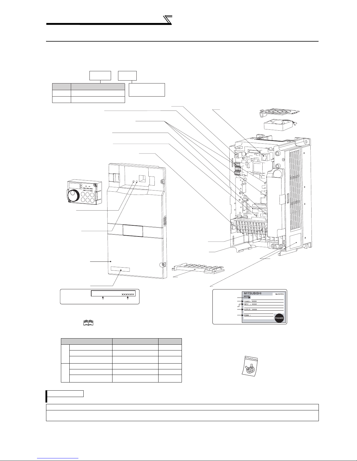
1.1 Product checking and parts identification
Unpack the inverter and check the capacity plate on the front cover and the rating plate on the inverter side face to
ensure that the product agrees with your order and the inverter is intact.
• Inverter Type
FR --A720
Symbol Voltage Class
Three-phase 200V class
A720
Three-phase 400V class
A740
RS-485 terminals
(Refer to page 311)
Connector for plug-in option connection
(Refer to the instruction manual of options.)
Voltage/current input switch
(Refer to page 14)
AU/PTC switchover switch
(Refer to the Instruction Manual (applied).)
EMC filter ON/OFF connector
(Refer to page 15)
Operation panel (FR-DU07)
(Refer to page 68)
Power lamp
Lit when the control circuit
(R1/L11, S1/L21) is supplied
ith power.
Alarm lamp
Lit when the inverter is
in the alarm status
(major fault).
Front cover
(Refer to page 6)
Capacity plate
Capacity plate
• Accessory
· Fan cover fixing screws (22K or less)
(Refer to
These screws are necessary for compliance with the
European Directive.
Capacity Screw Size (mm) Number
2
1.5K to 3.7K M3 × 35 1
0
5.5K to 11K M4 × 40 2
0
15K to 22K M4 × 50 1
V
4
2.2K, 3.7K M3 × 35 1
0
5.5K to 15K M4 × 40 2
0
18.5K, 22K M4 × 50 1
V
USB connector
FR-A720-3.7K
Inverter type
Instruction Manual (basic)
Serial number
K
3.7
Indicate inverter
capacity (kW)
(Refer to page 340)
Cooling fan
(Refer to page 408)
PU connector
(Refer to page 30)
Control circuit
terminal block
(Refer to page 28)
Main circuit
terminal block
(Refer to page 16)
Wiring cover
(Refer to page 21)
Rating plate
Rating plate
Inverter type
Applied motor
capacity
Input rating
Output rating
Serial number
FR-A720-3.7K
Charge lamp
Lit when power is
supplied to the main
circuit
(Refer to page 16)
)
· DC reactor supplied (75K or more)
· Eyebolt for hanging the inverter (30K to
280K)
M8 × two pieces
REMARKS
For removal and reinstallation of covers, refer to page 6.
Harmonic suppression guideline
All models of general-purpose inverters used by specific consumers are covered by "Harmonic suppression guideline for consumers who
receive high voltage or special high voltage". (For further details, refer to page 59.)
2
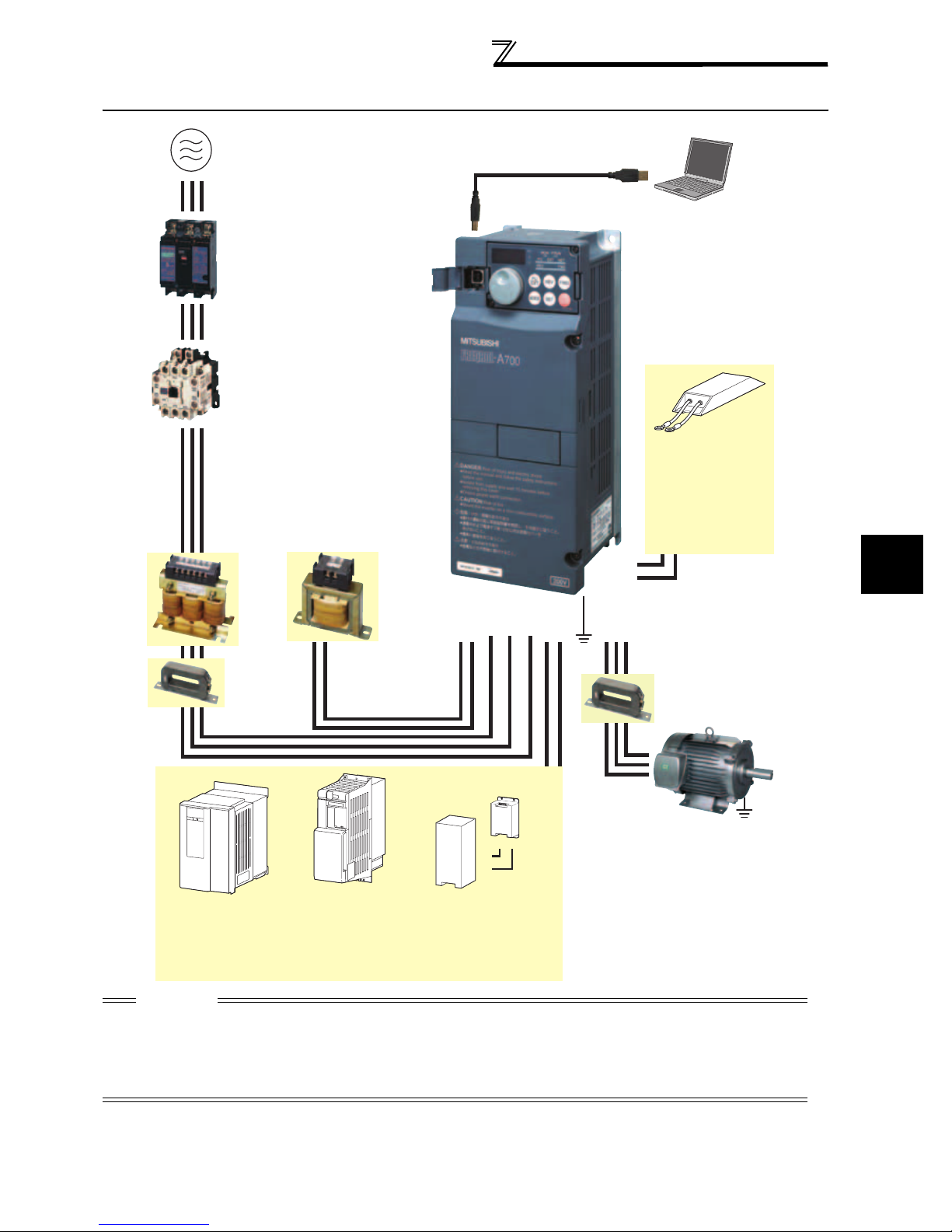
1.2 Inverter and peripheral devices
Inverter and peripheral devices
Three-phase AC power supply
Use within the permissible power supply
specifications of the inverter.
(Refer to page 418)
Moulded case circuit breaker (MCCB) or
earth leakage current breaker (ELB),
fuse
The breaker must be selected carefully
since an in-rush current flows in the inverter
at power on.
(Refer to page 4)
Magnetic contactor (MC)
Install the magnetic contactor to ensure
safety. Do not use this magnetic contactor
to start and stop the inverter. Doing so will
cause the inverter life to be shorten.
(Refer to page 63)
Reactor (FR-HAL, FR-HEL option)
Reactors (option) must be used when power
harmonics measures are taken, the power factor is
to be improved or the inverter is installed near a
large power supply system (1000kVA or more).
The inverter may be damaged if you do not use
reactors. Select the reactor according to the model.
Remove the jumpers across terminals P/+ - P1 to
connect the DC reactor to the 55K or less.
(Refer to page 62 )
AC reactor
(FR-HAL)
USB connector
A personal computer and an inverter can
be connected with a USB (Ver1. 1) cable.
(Refer to page 340)
Inverter (FR-A700)
The life of the inverter is influenced by
ambient temperature. The ambient
temperature should be as low as possible
within the permissible range. This must be
noted especially when the inverter is
installed in an enclosure. (Refer to page 8)
Wrong wiring might lead to damage of the
inverter. The control signal lines must be
kept fully away from the main circuit to
protect them from noise.(Refer to page 14)
Refer to page 15 for the built-in EMC filter.
P/+
PR
High-duty brake resistor
(FR-ABR
Braking capability of the
inverter built-in brake can be
improved. Remove the jumper
across terminal PR-PX when
connecting the high-duty brake
resistor. (7.5K or less)
*3 Compatible with the 22K or less.
*3
)
1
Noise filter
(FR-BSF01, FR-BLF)
V
Install a noise filter to reduce
the electromagnetic noise
generated from the inverter.
Effective in the range from
about 1MHz to 10MHz. A wire
should be wound four turns at
a maximum.
Motor
Earth (Ground)
Noise filter
(FR-BLF)
The 55K or less has
a built-in common
mode core.
High power factor converter
*1
, MT-HC*2)
(FR-HC
Power supply harmonics can
be greatly suppressed.
Install this as required.
*1 Compatible with the 55K or less.
*2 Compatible with the 75K or more.
DC reactor (FR-HEL)
For the 75K or more, a
DC reactor is supplied.
Always install the reactor.
Power regeneration
common converter (FR-CV
Power regeneration
converter (MT-RC
Great braking capability is obtained.
Install this as required.
*1
)
*2
)
R/L1 S/L2 T/L3
P1P/+ N/-P/+
Brake unit
*1
, MT-BU5*2)
(FR-BU
PR
P/+
P/+
PR
Resistor unit
*1
(FR-BR
, MT-BR5*2)
The regenerative braking
capability of the inverter can
be exhibited fully.
Install this as required.
UW
Earth
(Ground)
Devices connected to the output
Do not install a power factor correction capacitor,
surge suppressor or radio noise filter on the output
side of the inverter. When installing a moulded case
circuit breaker on the output side of the inverter,
contact each manufacturer for selection of the
moulded case circuit breaker.
Earth (Ground)
To prevent an electric shock, always earth (ground) the
motor and inverter. For reduction of induction noise
from the power line of the inverter, it is recommended
to wire the earth (ground) cable by returning it to the
earth (ground) terminal of the inverter.
CAUTION
·
Do not install a power factor correction capacitor, surge suppressor or radio noise filter on the inverter output side. This will cause the
inverter to trip or the capacitor, and surge suppressor to be damaged. If any of the above devices are connected, immediately remove them.
· Electromagnetic wave interference
The input/output (main circuit) of the inverter includes high frequency components, which may interfere with the communication
devices (such as AM radios) used near the inverter. In this case, set the EMC filter valid to minimize interference.
(Refer to
page 15
· Refer to the instruction manual of each option and peripheral devices for details of peripheral devices.
.)
OUTLINE
3
Inverter and peripheral devices
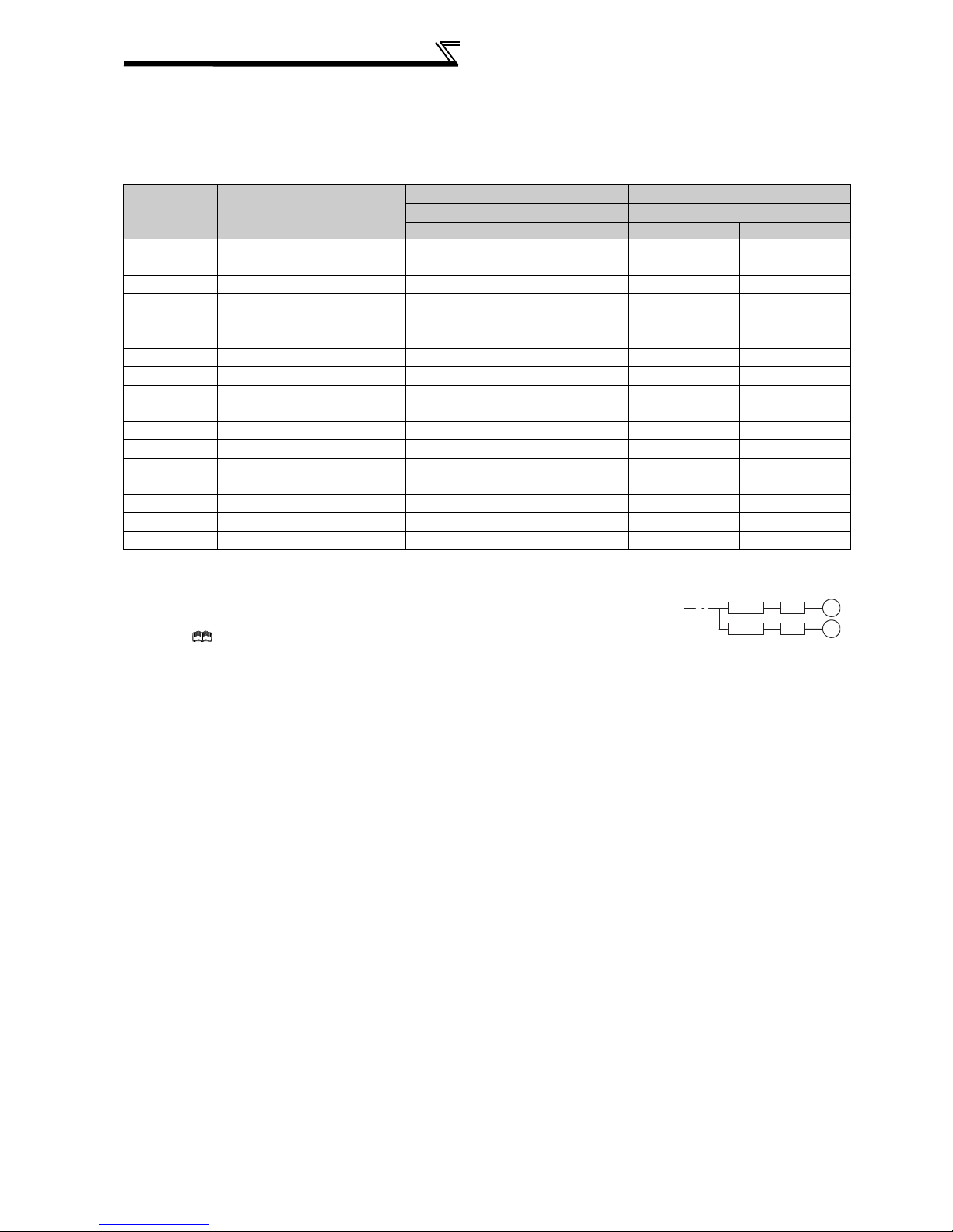
1.2.1 Peripheral devices
Check the motor capacity of the inverter you purchased. Appropriate peripheral devices must be selected according to
the capacity. Refer to the following list and prepare appropriate peripheral devices:
200V class
Motor Output
(kW)
*1
Applicable Inverter Type
0.4 FR-A720-0.4K 30AF 5A 30AF 5A S-N10 S-N10
0.75 FR-A720-0.75K 30AF 10A 30AF 10A S-N10 S-N10
1.5 FR-A720-1.5K 30AF 15A 30AF 15A S-N10 S-N10
2.2 FR-A720-2.2K 30AF 20A 30AF 15A S-N10 S-N10
3.7 FR-A720-3.7K 30AF 30A 30AF 30A S-N20, N21 S-N10
5.5 FR-A720-5.5K 50AF 50A 50AF 40A S-N25 S-N20, N21
7.5 FR-A720-7.5K 100AF 60A 50AF 50A S-N25 S-N25
11 FR-A720-11K 100AF 75A 100AF 75A S-N35 S-N35
15 FR-A720-15K 225AF 125A 100AF 100A S-N50 S-N50
18.5 FR-A720-18.5K 225AF 150A 225AF 125A S-N65 S-N50
22 FR-A720-22K 225AF 175A 225AF 150A S-N80 S-N65
30 FR-A720-30K 225AF 225A 225AF 175A S-N95 S-N80
37 FR-A720-37K 400AF 250A 225AF 225A S-N150 S-N125
45 FR-A720-45K 400AF 300A 400AF 300A S-N180 S-N150
55 FR-A720-55K 400AF 400A 400AF 350A S-N220 S-N180
75 FR-A720-75K 400AF 400A
90 FR-A720-90K 400AF 400A
Breaker Selection*2,4 Input Side Magnetic Contactor*3
Reactor connection Reactor connection
without with
without
with
S-N300
S-N300
*1 Selections for use of the Mitsubishi 4-pole standard motor with power supply voltage of 200VAC 50Hz.
*2 Select the MCCB according to the inverter power supply capacity.
Install one MCCB per inverter.
For installations in the United States or Canada, use the fuse certified by the UL and cUL.
(Refer to Instruction Manual (basics).)
*3 Magnetic contactor is selected based on the AC-1 class. The electrical durability of magnetic contactor is 500,000 times. When the magnetic
contactor is used for emergency stop during motor driving, the electrical durability is 25 times.
When using the MC for emergency stop during motor driving or using on the motor side during commercial-power supply operation, select the MC
with class AC-3 rated current for the motor rated current.
*4 When the breaker on the inverter primary side trips, check for the wiring fault (short circuit), damage to internal parts of the inverter, etc. Identify
the cause of the trip, then remove the cause and power on the breaker.
MCCB INV
MCCB INV
IM
IM
4
Inverter and peripheral devices
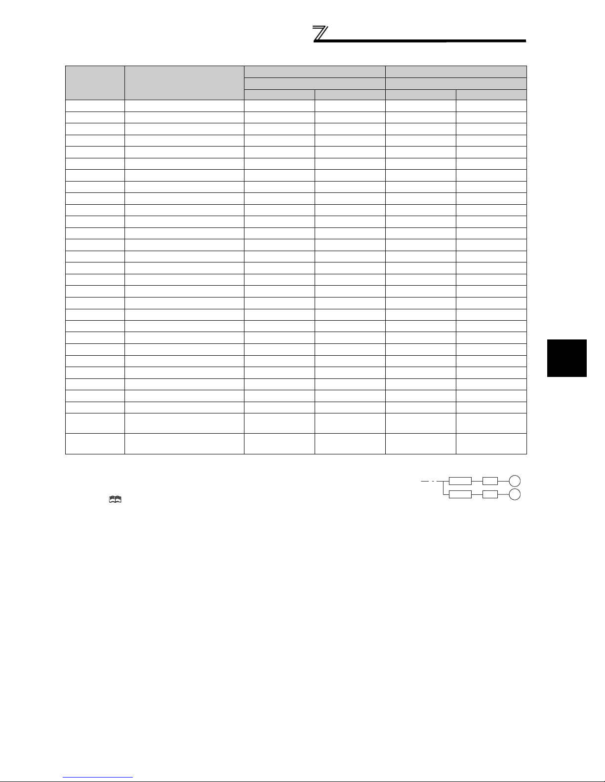
400V class
Motor Output
(kW)
*1
Applicable Inverter Type
0.4 FR-A740-0.4K 30AF 5A 30AF 5A S-N10 S-N10
0.75 FR-A740-0.75K 30AF 5A 30AF 5A S-N10 S-N10
1.5 FR-A740-1.5K 30AF 10A 30AF 10A S-N10 S-N10
2.2 FR-A740-2.2K 30AF 10A 30AF 10A S-N10 S-N10
3.7 FR-A740-3.7K 30AF 20A 30AF 15A S-N10 S-N10
5.5 FR-A740-5.5K 30AF 30A 30AF 20A S-N20 S-N11, N12
7.5 FR-A740-7.5K 30AF 30A 30AF 30A S-N20 S-N20
11 FR-A740-11K 50AF 50A 50AF 40A S-N20 S-N20
15 FR-A740-15K 100AF 60A 50AF 50A S-N25 S-N20
18.5 FR-A740-18.5K 100AF 75A 100AF 60A S-N25 S-N25
22 FR-A740-22K 100AF 100A 100AF 75A S-N35 S-N25
30 FR-A740-30K 225AF 125A 100AF 100A S-N50 S-N50
37 FR-A740-37K 225AF 150A 225AF 125A S-N65 S-N50
45 FR-A740-45K 225AF 175A 225AF 150A S-N80 S-N65
55 FR-A740-55K 225AF 200A 225AF 175A S-N80 S-N80
75 FR-A740-75K 225AF 225A S-N95
90 FR-A740-90K 225AF 225A S-N150
110 FR-A740-110K 225AF 225A S-N180
132 FR-A740-132K 400AF 400A S-N220
160 FR-A740-160K 400AF 400A S-N300
185 FR-A740-185K 400AF 400A S-N300
220 FR-A740-220K 600AF 500A S-N400
250 FR-A740-250K 600AF 600A S-N600
280 FR-A740-280K 600AF 600A S-N600
315 FR-A740-315K 800AF 700A S-N600
355 FR-A740-355K 800AF 800A S-N600
400 FR-A740-400K 1000AF 900A S-N800
450 FR-A740-450K 1000AF 1000A
500 FR-A740-500K 1200AF 1200A
*1 Selections for use of the Mitsubishi 4-pole standard motor with power supply voltage of 400VAC 50Hz.
*2 Select the MCCB according to the inverter power supply capacity.
Install one MCCB per inverter.
For installations in the United States or Canada, use the fuse certified by the UL and cUL.
(Refer to Instruction Manual (basics).)
*3 Magnetic contactor is selected based on the AC-1 class. The electrical durability of magnetic contactor is 500,000 times. When the magnetic
contactor is used for emergency stop during motor driving, the electrical durability is 25 times.
When using the MC for emergency stop during motor driving or using on the motor side during commercial-power supply operation, select the MC
with class AC-3 rated current for the motor rated current.
*4 When the breaker on the inverter primary side trips, check for the wiring fault (short circuit), damage to internal parts of the inverter, etc. Identify
the cause of the trip, then remove the cause and power on the breaker.
Breaker Selection*2,4 Input Side Magnetic Contactor*3
Reactor connection Reactor connection
without with
without
with
1000A
Rated product
1000A
Rated product
MCCB INV
MCCB INV
IM
IM
1
OUTLINE
5
Method of removal and reinstallation of the
front cover
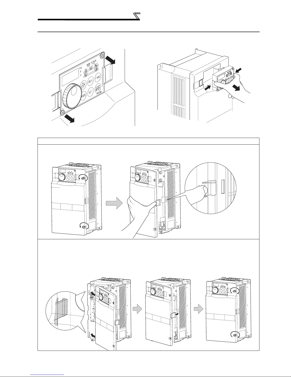
1.3 Method of removal and reinstallation of the front cover
•Removal of the operation panel
1) Loosen the two screws on the operation panel.
(These screws cannot be removed.)
When reinstalling the operation panel, insert it straight to reinstall securely and tighten the fixed screws of the
operation panel.
FR-A720-0.4K to 22K, FR-A740-0.4K to 22K
•
Removal
1) Loosen the installation screws of the
front cover.
2) Pull the front cover toward you to remove by pushing an
installation hook using left fixed hooks as supports.
2) Push the left and right hooks of the operation panel
and pull the operation panel toward you to remove.
Front cover
•Reinstallation
1) Insert the two fixed hooks on the left side of
the front cover into the sockets of the
inverter.
Front cover
Front cover
2) Using the fixed hooks as supports,
securely press the front cover
against the inverter.
(Although installation can be done
with the operation panel mounted,
make sure that a connector is
securely fixed.)
Front cover
Installation hook
3) Tighten the installation
screws and fix the front
cover.
Front cover
6
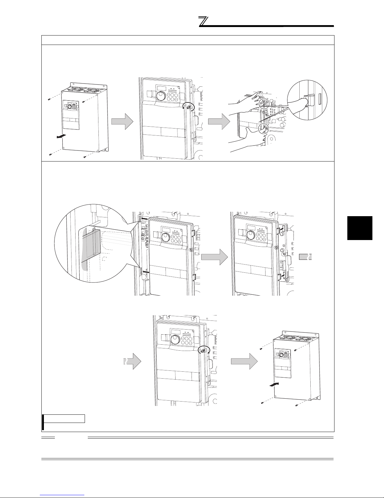
FR-A720-30K or more, FR-A740-30K or more
•
Removal
1) Remove installation screws on
the front cover 1 to remove the
2) Loosen the installation
screws of the front cover 2.
front cover 1.
Front cover 1
Front cover 2
•Reinstallation
1) Insert the two fixed hooks on the left side of the
front cover 2 into the sockets of the inverter.
Method of removal and reinstallation of the
front cover
3) Pull the front cover 2 toward you to
remove by pushing an installation
hook on the right side using left
fixed hooks as supports.
Installation hook
2) Using the fixed hooks as supports, securely
press the front cover 2 against the inverter.
(Although installation can be done with the
operation panel mounted, make sure that a
connector is securely fixed.)
Front cover 2 Front cover 2
3) Fix the front cover 2 with the
installation screws.
Front cover 2
1
OUTLINE
4) Fix the front cover 1 with the
installation screws.
Front cover 1
REMARKS
⋅ For the FR-A720-55K and the FR-A740-160K or more, the front cover 1 is separated into two parts.
CAUTION
1. Fully make sure that the front cover has been reinstalled securely. Always tighten the installation screws of the front cover.
2. The same serial number is printed on the capacity plate of the front cover and the rating plate of the inverter. Before reinstalling the front
cover, check the serial numbers to ensure that the cover removed is reinstalled to the inverter from where it was removed.
7

Installation of the inverter and enclosure
design
1.4 Installation of the inverter and enclosure design
When an inverter enclosure is to be designed and manufactured, heat generated by contained equipment, etc., the
environment of an operating place, and others must be fully considered to determine the enclosure structure, size and
equipment layout. The inverter unit uses many semiconductor devices. To ensure higher reliability and long period of
operation, operate the inverter in the ambient environment that completely satisfies the equipment specifications.
1.4.1 Inverter installation environment
As the inverter installation enviromnet should satisfiy the standard specifications indicated in the following table,
operation in any place that does not meet these conditions not only deteriorates the performance and life of the
inverter, but also causes a failure. Refer to the following points and take adequate measures.
Environmental standard specifications of inverter
Item Description
Ambient temperature -10 to +50°C (non-freezing)
Ambient humidity 90% RH maximum (non-condensing)
Atmosphere Free from corrosive and explosive gases, dust and dirt
Maximum Altitude 1,000m or less
Vibration
*1 2.9m/s2 or less for the 160K or more.
(1) Temperature
The permissible ambient temperature of the inverter is between -10°C and +50°C. Always operate the inverter within
this temperature range. Operation outside this range will considerably shorten the service lives of the semiconductors,
parts, capacitors and others. Take the following measures so that the ambient temperature of the inverter falls within
the specified range.
1)Measures against high temperature
• Use a forced ventilation system or similar cooling system. (Refer to page 10.)
• Install the enclosure in an air-conditioned electrical chamber.
• Block direct sunlight.
• Provide a shield or similar plate to avoid direct exposure to the radiated heat and wind of a heat source.
• Ventilate the area around the enclosure well.
2)Measures against low temperature
• Provide a space heater in the enclosure.
• Do not power off the inverter. (Keep the start signal of the inverter off.)
3)Sudden temperature changes
• Select an installation place where temperature does not change suddenly.
• Avoid installing the inverter near the air outlet of an air conditioner.
• If temperature changes are caused by opening/closing of a door, install the inverter away from the door.
2
or less *1 (JIS C 60068-2-6 compliant)
5.9m/s
(2) Humidity
Normally operate the inverter within the 45 to 90% range of the ambient humidity. Too high humidity will pose problems
of reduced insulation and metal corrosion. On the other hand, too low humidity may produce a spatial electrical
breakdown. The insulation distance specified in JEM1103 "Control Equipment Insulator" is defined as humidity 45 to
85%.
1)Measures against high humidity
• Make the enclosure enclosed, and provide it with a hygroscopic agent.
• Take dry air into the enclosure from outside.
• Provide a space heater in the enclosure.
2)Measures against low humidity
What is important in fitting or inspection of the unit in this status is to discharge your body (static electricity)
beforehand and keep your body from contact with the parts and patterns, besides blowing air of proper humidity into
the enclosure from outside.
3)Measures against condensation
Condensation may occur if frequent operation stops change the in-enclosure temperature suddenly or if the outsideair temperature changes suddenly.
Condensation causes such faults as reduced insulation and corrosion.
• Take the measures against high humidity in 1).
• Do not power off the inverter. (Keep the start signal of the inverter off.)
8

Installation of the inverter and enclosure
design
(3) Dust, dirt, oil mist
Dust and dirt will cause such faults as poor contact of contact points, reduced insulation or reduced cooling effect due
to moisture absorption of accumulated dust and dirt, and in-enclosure temperature rise due to clogged filter.
In the atmosphere where conductive powder floats, dust and dirt will cause such faults as malfunction, deteriorated
insulation and short circuit in a short time.
Since oil mist will cause similar conditions, it is necessary to take adequate measures.
Countermeasures
• Place in a totally enclosed enclosure.
Take measures if the in-enclosure temperature rises. (Refer to page 10.)
• Purge air.
Pump clean air from outside to make the in-enclosure pressure higher than the outside-air pressure.
(4) Corrosive gas, salt damage
If the inverter is exposed to corrosive gas or to salt near a beach, the printed board patterns and parts will corrode or
the relays and switches will result in poor contact.
In such places, take the measures given in Section (3).
(5) Explosive, flammable gases
As the inverter is non-explosion proof, it must be contained in an explosion proof enclosure.
In places where explosion may be caused by explosive gas, dust or dirt, an enclosure cannot be used unless it
structurally complies with the guidelines and has passed the specified tests. This makes the enclosure itself expensive
(including the test charges).
The best way is to avoid installation in such places and install the inverter in a non-hazardous place.
(6) Highland
Use the inverter at the altitude of within 1000m.
If it is used at a higher place, it is likely that thin air will reduce the cooling effect and low air pressure will deteriorate
dielectric strength.
(7) Vibration, impact
The vibration resistance of the inverter is up to 5.9m/s2 (2.9m/s2 for the 160K or more) at 10 to 55Hz frequency and
1mm amplitude as specified in JIS C 60068-2-6.
Vibration or impact, if less than the specified value, applied for a long time may make the mechanism loose or cause
poor contact to the connectors.
Especially when impact is imposed repeatedly, caution must be taken as the part pins are likely to break.
Countermeasures
• Provide the enclosure with rubber vibration isolators.
• Strengthen the structure to prevent the enclosure from resonance.
• Install the enclosure away from sources of vibration.
1
OUTLINE
9
Installation of the inverter and enclosure
design
1.4.2 Cooling system types for inverter enclosure
From the enclosure that contains the inverter, the heat of the inverter and other equipment (transformers, lamps,
resistors, etc.) and the incoming heat such as direct sunlight must be dissipated to keep the in-enclosure temperature
lower than the permissible temperatures of the in-enclosure equipment including the inverter.
The cooling systems are classified as follows in terms of the cooling calculation method.
1) Cooling by natural heat dissipation from the enclosure surface (Totally enclosed type)
2) Cooling by heat sink (Aluminum fin, etc.)
3) Cooling by ventilation (Forced ventilation type, pipe ventilation type)
4) Cooling by heat exchanger or cooler (Heat pipe, cooler, etc.)
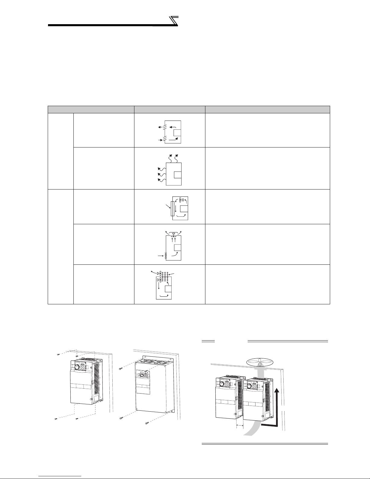
Cooling System Enclosure Structure Comment
Natural
cooling
Forced
cooling
Natural ventilation
(Enclosed, open type)
Natural ventilation (Totally
enclosed type)
Heatsink cooling
Forced ventilation
Heat pipe Totally enclosed type for enclosure downsizing.
Heatsink
INV
INV
INV
INV
Heat
pipe
INV
Low in cost and generally used, but the enclosure size
increases as the inverter capacity increases. For
relatively small capacities.
Being a totally enclosed type, the most appropriate for
hostile environment having dust, dirt, oil mist, etc. The
enclosure size increases depending on the inverter
capacity.
Having restrictions on the heatsink mounting position
and area, and designed for relative small capacities.
For general indoor installation. Appropriate for enclosure
downsizing and cost reduction, and often used.
1.4.3 Inverter placement
(1) Installation of the Inverter
Installation on the enclosure
0.4K to 22K 30K or more
Fix six positions for the FR-A740-160K to 355K
and fix eight positions for the FR-A740-400K to
500K.
10
CAUTION
When encasing multiple inverters, install them in parallel as
a cooling measure. Install the inverter vertically.
Vertical
*
* Refer to the clearances on the next page.
Installation of the inverter and enclosure
design
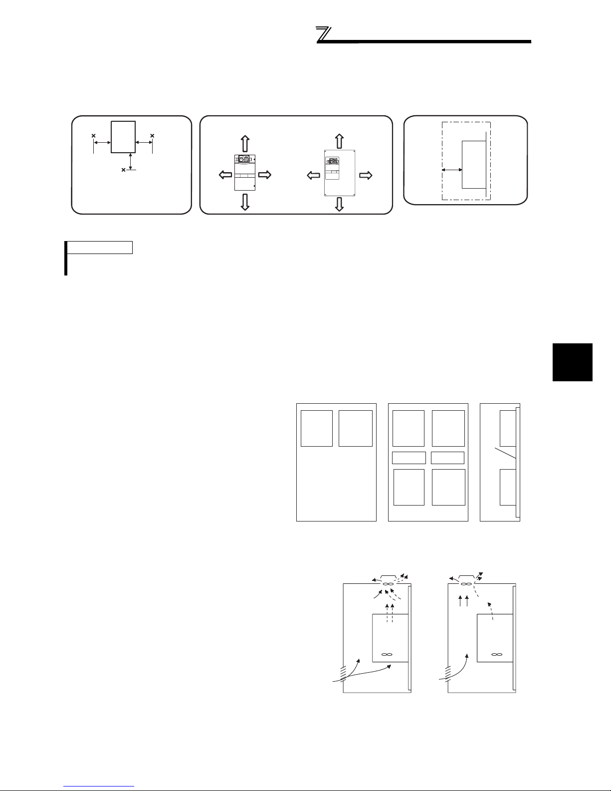
(2) Clearances around the inverter
To ensure ease of heat dissipation and maintenance, leave at least the shown clearances around the inverter. At least the
following clearances are required under the inverter as a wiring space, and above the inverter as a heat dissipation space.
Inverter
5cm
Measurement
position
Temperature:
Measurement
position
5cm
5cm
ClearancesAmbient temperature and humidity
55K or less 75K or more
10cm or more
5cm
or more *
5cm
or more *
10cm
or more
(front)
20cm or more
10cm
or more
Clearances (side)
Inverter
5cm
or more
-10°C to 50°C
Ambient humidity:
90% RH maximum
Leave enough clearances and take
cooling measures.
10cm or more
*1cm or more for 3.7K or less
20cm or more
REMARKS
For replacing the cooling fan of the 160K or more, 30cm of space is necessary in front of the inverter. Refer to page 408 for fan
replacement.
(3) Inverter mounting orientation
Mount the inverter on a wall as specified. Do not mount it horizontally or any other way.
(4) Above the inverter
Heat is blown up from inside the inverter by the small fan built in the unit. Any equipment placed above the inverter
should be heat resistant.
(5) Arrangement of multiple inverters
1
When multiple inverters are placed in the same
enclosure, generally arrange them horizontally as
shown in the right figure (a). When it is inevitable to
arrange them vertically to minimize space, take such
Inverter
measures as to provide guides since heat from the
bottom inverters can increase the temperatures in the
top inverters, causing inverter failures.
When mounting multiple inverters, fully take caution
not to make the ambient temperature of the inverter
higher than the permissible value by providing
ventilation and increasing the enclosure size.
(a) Horizontal arrangement
(6) Placement of ventilation fan and inverter
Heat generated in the inverter is blown up from the bottom of
the unit as warm air by the cooling fan. When intalling a
ventilation fan for that heat, determine the place of ventilation
fan installation after fully considering an air flow. (Air passes
through areas of low resistance. Make an airway and airflow
plates to expose the inverter to cool air.)
Inverter
Enclosure Enclosure
Inverter
Guide Guide
Inverter
Inverter
Inverter
(b) Vertical arrangement
Arrangement of multiple inverters
Inverter Inverter
OUTLINE
Guide
<Good example> <Bad example>
Placement of ventilation fan and inverter
11

MEMO
12

2 WIRING
This chapter describes the basic "WIRING" for use of this
product.
Always read the instructions before using the equipment
2.1 Wiring ......................................................................14
2.2 Main circuit terminal specifications.......................... 16
2.3 Control circuit specifications.................................... 28
2.4 Connection of motor with encoder (vector control) .36
2.5 Connection of stand-alone option units................... 44
1
2
3
4
5
6
7
13
Wiring
2.1 Wiring
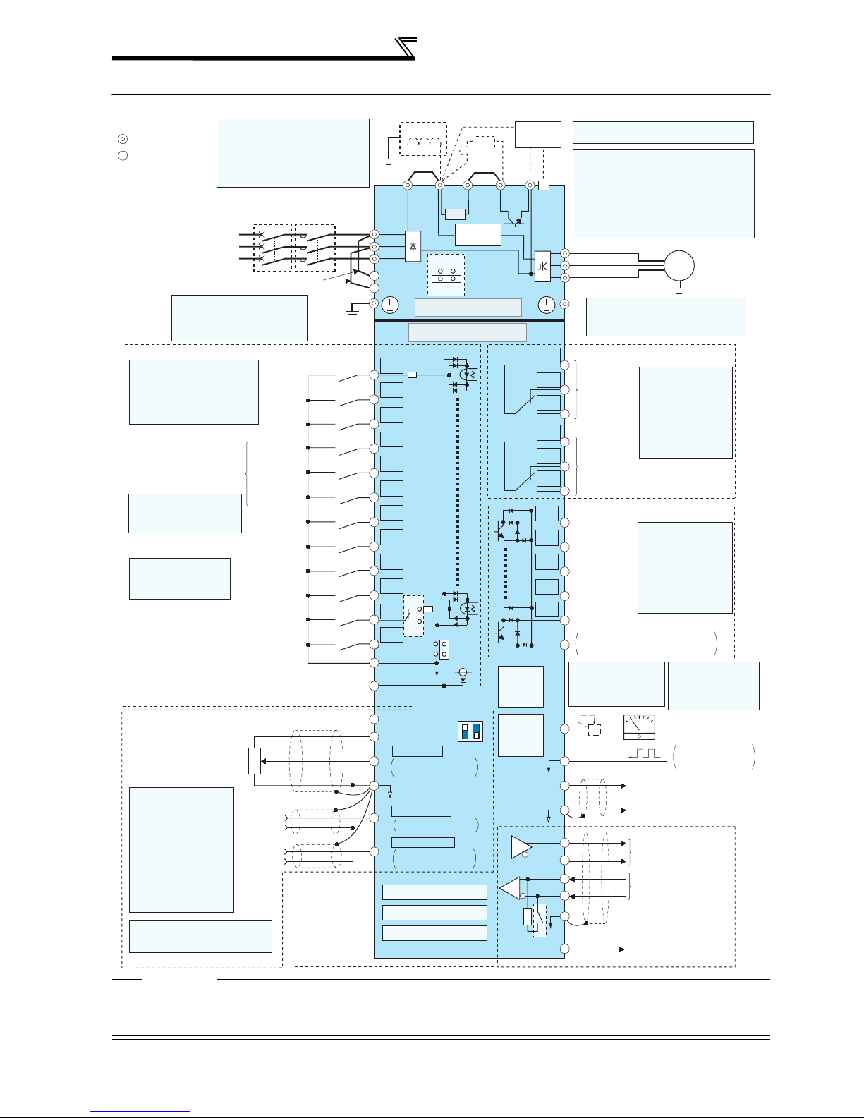
2.1.1 Terminal connection diagram
Sink logic
Main circuit terminal
Control circuit terminal
Three-phase AC
Control input signals (No voltage input allowed)
Terminal functions vary with
the input terminal
assignment (Pr. 178 to Pr. 189)
(Refer to page 221)
*3. JOG terminal can be used
as pulse train input terminal.
Use Pr.291 to select
JOG/pulse.
*4. AU terminal can be
used as PTC input
terminal.
(Common for external power supply transistor)
Frequency setting signal (Analog)
Frequency setting
*
Terminal input specifications
5.
can be changed by analog
input specifications
switchover (Pr. 73, Pr. 267).
Note that the current at
terminal 2 and 4 is always 4
to 20mA when the
voltage/current input switch is
set to ON. (A voltage/current
input switch is provided for
the 5.5K or more.)
(Refer to page 274)
*6
. It is recommended to use 2W1kΩ
when the frequency setting signal
is changed frequently.
*1. DC reactor (FR-HEL)
Be sure to connect the DC reactor
supplied with the 75K or more.
When a DC reactor is connected to
the 55K or less, remove the jumper
across P1-P/+.
MCCB
power supply
Jumper
*2. To supply power to the
control circuit separately,
remove the jumper across
R1/L11 and S1/L21.
Forward
rotation
start
Reverse
rotation
start
Start self-
holding selection
High speed
Multi-speed
selection
Middle
speed
Low speed
Jog mode
Second function selection
Output stop
Reset
Terminal 4 input selection
(Current input selection)
Selection of automatic restart
after instantaneous
power failure
Contact input common
24VDC power supply
3
potentiometer
1/2W1k
*6
2
Ω
1
Auxiliary
input
Terminal
4 input
(Current
input)
(+)
(+)
(-)
(-)
MC
*2
Earth
(Ground)
Connector
for plug-in option
connection
*1
Jumper
Earth
(Ground)
P1
R/L1
S/L2
T/L3
R1/L11
S1/L21
Main circuit
Control circuit
STF
STR
STOP
RH
RM
RL
JOG
*3
RT
MRS
RES
*4
AU
AU
PTC
CS
SD
PC
10E(+10V)
10(+5V)
2
5
1
4
Option connector 1
Option connector 2
Option connector 3
SOURCE
*5
Voltage/current
0 to 5VDC
0 to 10VDC
4 to 20mADC
(Analog common)
0 to
±
10VDC
0 to ±5VDC
4 to 20mADC
0 to 5VDC
0 to 10VDC
Jumper
Jumper
PX PR N/-P/+
R
Inrush current
limit circuit
ON
EMC filter
ON/OFF
connecter
OFF
SINK
24V
input switch
2
4
ON
OFF
(Initial value)
selected
(Initial value)
selected
(Initial value)
selected
R
*8
*5
*5
*5
Brake unit
(Option)
*9
PU
connector
USB
connector
TXD+
RXD+
Terminating
resistor
CAUTION
· To prevent a malfunction due to noise, keep the signal cables more than 10cm away from the power cables.
· After wiring, wire offcuts must not be left in the inverter.
Wire offcuts can cause an alarm, failure or malfunction. Always keep the inverter clean.
When drilling mounting holes in an enclosure etc., take care not to allow chips and other foreign matter to enter the inverter.
*7. A CN8 connector is provided with the 75K
or more.
*8. Brake resistor (FR-ABR)
Remove the jumper across terminal PR-PX
when connecting a brake resistor.
CN8
(0.4K to 7.5K)
Terminal PR is provided for the 0.4K to 22K.
*7
Install a thermal relay to prevent an overheat
and burnout of the brake resistor.
(Refer to page 46)
U
V
W
*9.The FR-A720-0.4K and 0.75K
are not provided with the EMC
filter ON/OFF connector. (Always on)
C1
B1
A1
C2
B2
Relay output 1
(Alarm output)
Relay output 2
Terminal functions
vary with the output
terminal assignment
(Pr. 195, Pr. 196)
(Refer to page 228)
A2
RUN
Running
SU
Up to frequency
IPF
Instantaneous
power failure
OL
Overload
FU
Frequency detection
SE
*
10. It is not necessary
Open collector output common
Sink
when calibrating the
indicator from the
operation panel.
Open collector output
Terminal functions
vary with the output
terminal assignment
(Pr. 190 to Pr. 194)
(Refer to page 228)
/source common
+
FM
*11
Calibration
resistor *10
SD
AM
5
TXD-
RXD-
SG
VCC
(+)
(-)
Data transmission
Data reception
GND
5V
Motor
IM
Earth (Ground)
Relay output
*11. FM terminal can
be used for pulse
train output of open
collector output
using Pr.291.
-
Indicator
(Frequency meter, etc.)
Moving-coil type
1mA full-scale
Analog signal output
(0 to 10VDC)
RS-485 terminals
(Permissible load
current 100mA)
14
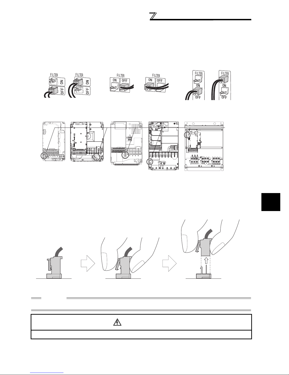
2.1.2 EMC filter
The inverter is equipped with a built-in EMC filter.
Effective for reduction of air-propagated noise on the input side of the inverter.
The EMC filter is factory-set to disable (OFF).
To enable it, fit the EMC filter ON/OFF connector to the ON position.
Wiring
3.7K or less
EMC filter OFF EMC filter OFF EMC filter OFFEMC filter ON EMC filter ON EMC filter ON
(initial setting) (initial setting) (initial setting)
FR-A720-1.5K to 3.7K
FR-A740-0.4K to 3.7K
FR-A720-5.5K, 7.5K
FR-A740-5.5K to 7.5K
FR-A740-11K, 15K
5.5K, 7.5K
FR-A720-11K
FR-A720-15K to 22K
FR-A740-18.5K to 22 K
11K or more
FR-A720-30K or more
FR-A740-30K or more
EMC filter
ON/OFF
connector
VUW
The FR-A720-0.4K and 0.75K are not provided with the EMC filter ON/OFF connector. (The EMC filter is always valid.)
<How to disconnect the connector>
(1) Before removing a front cover, check to make sure that the indication of the inverter operation panel is off, wait for
at least 10 minutes after the power supply has been switched off, and check that there are no residual voltage
using a tester or the like. (Refer to page 6.)
(2) When disconnecting the connector, push the fixing tab and pull the connector straight without pulling the cable or
forcibly pulling the connector with the tab fixed. When installing the connector, also engage the fixing tab securely.
(If it is difficult to disconnect the connector, use a pair of long-nose pliers, etc.)
2
EMC filter
ON/OFF connector
(Side view)
Disengage connector fixing tab With tab disengaged,
pull up the connector straight.
CAUTION
⋅ Fit the connector to either ON or OFF.
⋅ Enabling (turning on) the EMC filter increases leakage current. (Refer to page 55)
WARNING
While power is on or when the inverter is running, do not open the front cover. Otherwise you may get an electric shock.
WIRING
15

Main circuit terminal specifications
2.2 Main circuit terminal specifications
2.2.1 Specification of main circuit terminal
Term inal
Symbol
R/L1,
S/L2,
T/L3
U, V, W Inverter output Connect a three-phase squirrel-cage motor.
R1/L11,
S1/L21
P/+, PR
P/+, N/-
P/+, P1
PR, PX
Terminal Name Description
Connect to the commercial power supply.
AC power input
Power supply for
control circuit
Brake resistor
connection
Brake unit
connection
(22K or less)
DC reactor
connection
Built-in brake circuit
connection
Earth (Ground)
Keep these terminals open when using the high power factor converter
(FR-HC and MT-HC) or power regeneration common converter (FR-CV).
Connected to the AC power supply terminals R/L1 and S/L2. To retain the
alarm display and alarm output or when using the high power factor
converter (FR-HC
(FR-CV), remove the jumpers from terminals R/L1-R1/L11 and S/L2-S1/
L21 and apply external power to these terminals.
Do not turn off the power supply for control circuit (R1/L11, S1/L21) with the
main circuit power (R/L1, S/L2, T/L3) on. Doing so may damage the
inverter. The circuit should be configured so that the main circuit power (R/
L1, S/L2, T/L3) is also turned off when the power supply for control circuit
(R1/L11, S1/L21) is off.
15Kor less : 60VA, 18.5K or more : 80VA
Remove the jumper from terminals PR-PX (7.5K or less) and connect an
optional brake resistor (FR-ABR) across terminals P/+-PR.
For the 22K or less, connecting the resistor further provides regenerative
braking power.
Connect the brake unit (FR-BU, BU and MT-BU5), power regeneration
common converter (FR-CV), high power factor converter (FR-HC and
MT-HC) or power regeneration converter (MT-RC).
For the 55K or less, remove the jumper across terminals P/+ - P1 and
connect the DC reactor. (As a DC reactor is supplied with the 75K or
more as standard, be sure to connect the DC reactor. )
When the jumper is connected across terminals PX-PR (initial status),
the built-in brake circuit is valid. (Provided for the 7.5K
For earthing (grounding) the inverter chassis. Must be earthed
(grounded).
and MT-HC
) or power regeneration common converter
or less.)
CAUTION
· When connecting a dedicated brake resistor (FR-ABR) and brake unit (FR-BU, BU) remove jumpers across terminals PR-PX
(7.5K or less). For details, refer to page 44 to 47.
16
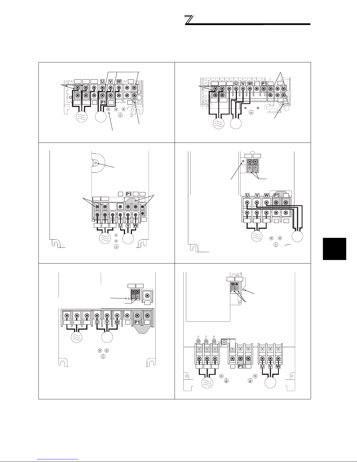
Main circuit terminal specifications
r
2.2.2 Terminal arrangement of the main circuit terminal, power supply and the motor
wiring.
200V class
FR-A720-0.4K, 0.75K FR-A720-1.5K, 2.2K, 3.7K
Screw size (M4)
Jumper
R/L1
R1/L11
Power supply
FR-A720-5.5K, 7.5K
Jumper
Screw size
T/L3
S/L2
N/-
S1/L21
P/+
IM
Motor
As this is an inside cover fixing screw,
do not remove it.
*
*
R1/L11 S1/L21
(M5)
R/L1 S/L2 T/L3
PR
PX
Screw size
(M4)
Charge lamp
N/-
Jumper
Charge lamp
*
P/+
PR
PX
*
Jumper
FR-A720-11K
Jumpe
Screw size (M4)
R/L1 S/L2 T/L3
R1/L11 S1/L21
Power
supply
Charge lamp
Screw size (M5)
IM
Motor
N/-
Screw size
(M4)
R1/L11 S1/L21
Screw size
(M4)
R/L1 S/L2 T/L3
Jumper
PR
P/+
PX
Charge lamp
Jumper
Jumper
N/-
P/+
PR
IM
Power supply
Screw size (M5)
* Screw size of terminal R1/L11, S1/L21, PR, and PX is M4.
FR-A720-15K, 18.5K, 22K FR-A720-30K, 37K, 45K
Screw size (M4)
Screw size
(15K:M6, 18.5K, 22K:M8)
R/L1 S/L2 T/L3
Charge lamp
IM
Power supply
Motor
Screw size (M6)
Jumper
Motor
R1/L11 S1/L21
N/-
Jumper
PR
P/+
Screw size
(M4)
R/L1 S/L2 T/L3
Power
supply
(30K:M6, 37K, 45K:M8)
Power supply
R1/L11 S1/L21
Charge lamp
Jumper
Screw size
(30K:M8, 37K, 45K:M10)
N/-
P/+
Jumper
Screw size
Screw size (M5)
IM
Motor
IM
Motor
2
WIRING
17
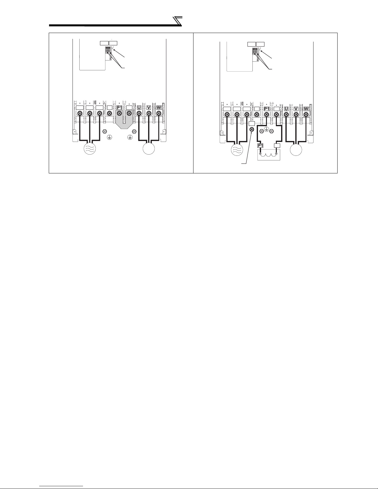
Main circuit terminal specifications
FR-A720-55K FR-A720-75K, 90K
R1/L11 S1/L21
Screw size (M4)
R1/L11 S1/L21
Screw size (M4)
R/L1 S/L2 T/L3
Power supply
Charge lamp
Jumper
Screw size (M12)
N/-
Screw size (M8)
P/+
Jumper
IM
Motor
R/L1 S/L2 T/L3
Power supply
Screw size (M12)
(for option)
N/-
P/+
Charge lamp
Jumper
P/+
Screw size
(M10)
P/+
DC reactor
Screw size (M12)
IM
Motor
18
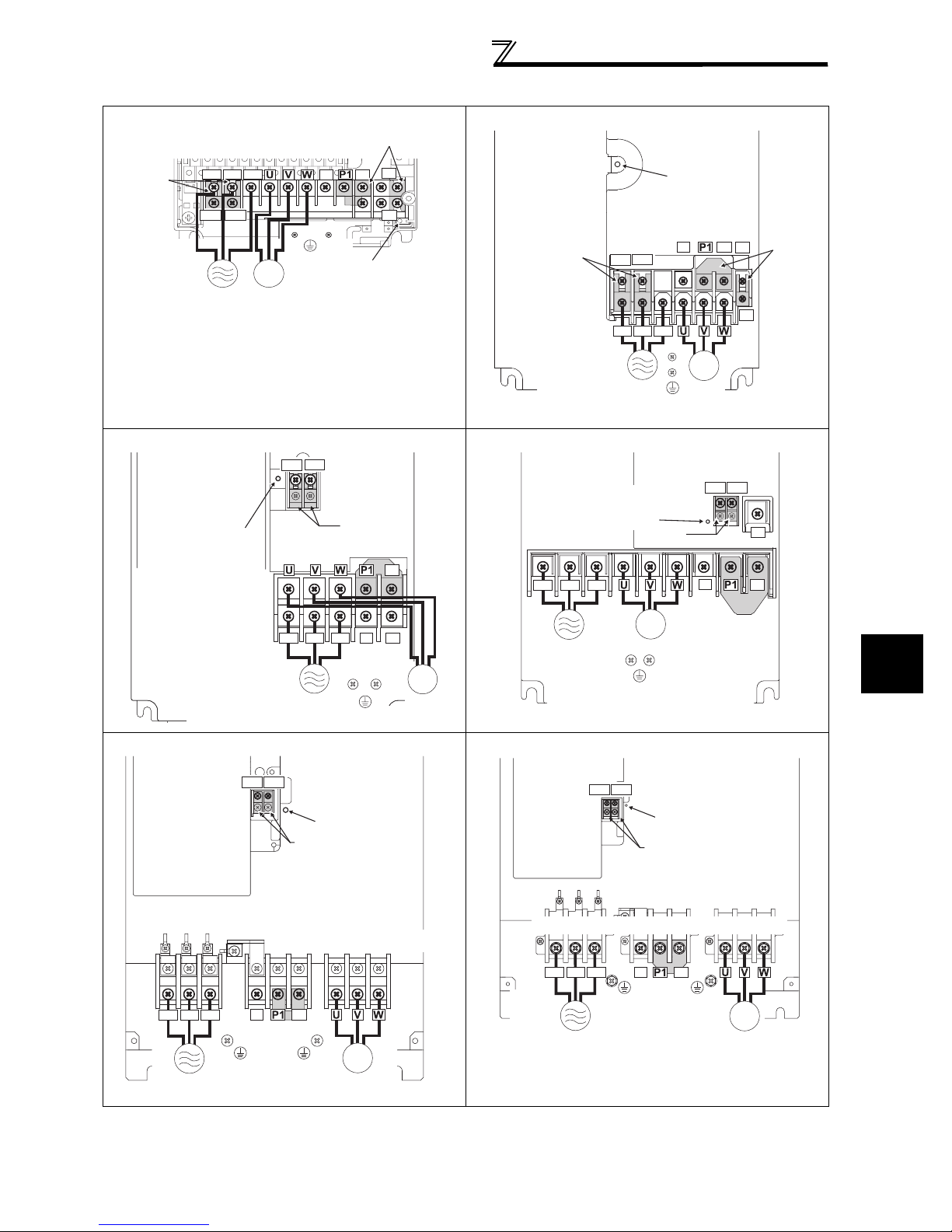
Main circuit terminal specifications
r
IM
Jumper
Jumper
Charge lamp
Screw size (M4)
Power
supply
Motor
R/L1 S/L2 T/L3
N/-
P/+
R1/L11 S1/L21
Screw size (M8) Screw size (M10) Screw size (M8)
Screw size (M8)
400V class
FR-A740-0.4K to 3.7K FR-A740-5.5K, 7.5K
Jumper
Screw size (M4)
R/L1 S/L2 T/L3
N/-
P/+
Jumper
PR
Charge lamp
R1/L11 S1/L21
Power
supply
IM
Motor
Screw size
(M4)
PX
Charge lamp
Jumper
Screw size
FR-A740-11K, 15K FR-A740-18.5K, 22K
R1/L11 S1/L21
Screw size
(M4)
Charge lamp
Screw size (M5)
R/L1 S/L2 T/L3
Jumper
Jumper
N/-
P/+
PR
Screw size (M6)
R/L1 S/L2 T/L3
Power supply
IM
Power supply
Screw size (M5)
FR-A740-30K, 37K, 45K FR-A740-55K
R1/L11 S1/L21
Screw size(M4)
Charge lamp
Jumper
Motor
R1/L11 S1/L21
(M4)
R/L1 S/L2 T/L3
Power supply
Charge lamp
Screw size (M6)
N/-
IM
Motor
Screw size
(M4)
Screw size (M4)
Jumper
IM
Motor
P/+
PR
R1/L11 S1/L21
N/-
Jumper
Jumpe
PX
PR
P/+
2
WIRING
R/L1 S/L2 T/L3
Power
supply
(30K: M6, 37K, 45K: M8)
Screw size (30K: M6, 37K, 45K: M8)
N/-
P/+
Jumper
Screw size
IM
Motor
19
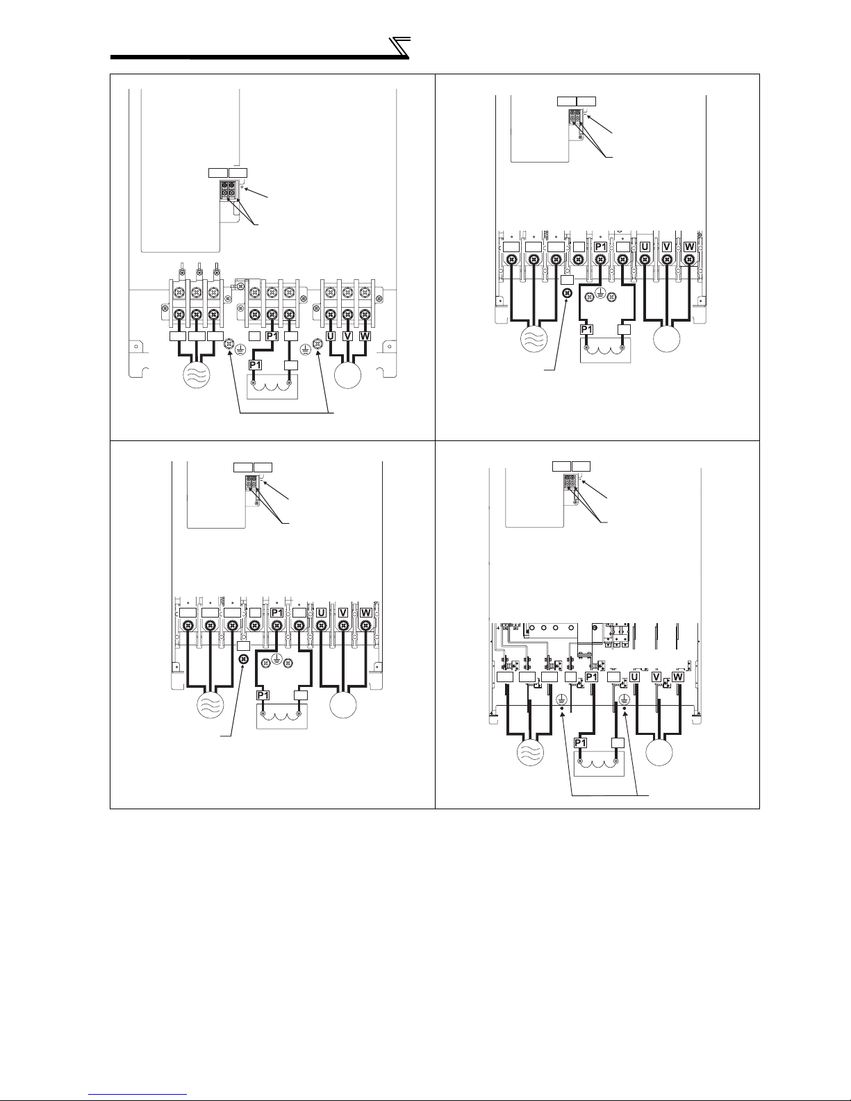
Main circuit terminal specifications
FR-A740-75K, 90K FR-A740-110K, 132K
R1/L11 S1/L21
Screw size (M4)
R/L1 S/L2 T/L3
Power
supply
Charge lamp
Jumper
N/-
DC reactor
P/+
P/+
Screw size
IM
Motor
Screw size
(M10)
R/L1 S/L2 T/L3
(M10)
Power supply
Screw size (M12)
(for option)
R1/L11 S1/L21
N/-
P/+
Screw size
(M10)
DC reactor
Screw size (M4)
Charge lamp
Jumper
Screw size (M10)
P/+
P/+
IM
Motor
FR-A740-160K, 185K FR-A740-220K to 500K
R1/L11 S1/L21
Screw size (M4)
Charge lamp
Jumper
Screw size (M12)
P/+
N/-
Screw size
(M10)
P/+
R/L1 S/L2 T/L3
P/+
R/L1 S/L2 T/L3
IM
Power supply
Screw size (M12)
(for option)
DC reactor
Motor
Power supply
R1/L11 S1/L21
N/-
DC reactor
Screw size (M4)
Charge lamp
Jumper
Screw size (M12)
P/+
P/+
IM
Motor
Screw size (M10)
20
 Loading...